Embed Size (px)
Citation preview


Infrastructure Design Directive (IDD-2005-05) 7-July-2005 Page 2
Accessing the Standard Drawings Master List The Active Standard Drawings Master List can be found in the \\asgopinon\psespecs shared drive.
Non-Departmental personnel shall continue to communicate with the Standards and Specifications Unit for the Active Standard Drawings Master List, as well as other listings that are required for NMDOT projects. Contact:
Norbert (Bert) Baca, P.E.: 505.827.5320 email [email protected]
General Office staff is to utilize the \\asgopinon\pseshare drive to access the Directive. District and Regional Office staff can access the Directive utilizing the appropriate District drive as indicated below:
District 1 \\d1flsv03\design$ District 2 \\d2flsv01\public\pse_section District 3 \\d3flsv03\ps&e_section District 4 \\d4flsv04\designshared District 5 \\D5flsv02a\D5Design District 6 \\d6flsv02\pse_section
Infrastructure Design Directive (IDD-2005-05) 7-July-2005 Page 3
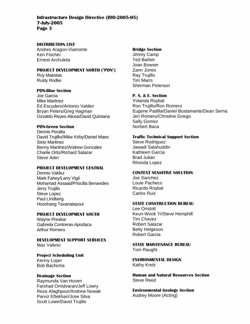
DISTRIBUTION LIST Andres Aragon-Viamonte Ken Fischer Ernest Archuleta PROJECT DEVELOPMENT NORTH ("PDN") Roy Maestas Rusty Rodke PDN-Blue Section Joe Garcia Mike Martinez Ed Escudero/Antonio Valdez Bryan Peters/Greg Hagman Ozvaldo Reyes-Alicea/David Quintana PDN-Green Section Dennis Peralta David Trujillo//Mike Kirby/Daniel Maes Sixto Martinez Benny Martinez/Andrew Gonzales Charlie Ortiz/Richard Salazar Steve Ader PROJECT DEVELOPMENT CENTRAL Dennis Valdez Mark Fahey/Larry Vigil Mohamad Assaad/Priscilla Benavides Jerry Trujillo Steve Lopez Paul LIndberg Hooshang Tavanaiepour PROJECT DEVELOPMENT SOUTH Wayne Preskar Gabriela Contreras-Apodaca Arthur Romero DEVELOPMENT SUPPORT SERVICES Max Valerio Project Scheduling Unit Kenny Lujan Bob Bachicha Drainage Section Raymunda Van Hoven Farshad Omidvaran/Jeff Lowry Reza Afaghpour/Andrew Nowak Parviz Eftekhari/Jose Silva Scott Lowe/David Trujillo
Bridge Section Jimmy Camp Ted Barber Joan Bowser Zann Jones Ray Trujillo Tim Marrs Sherman Peterson P. S. & E. Section Yolanda Roybal Ron Trujillo/Ron Romero Eugene Padilla/Daniel Bustamante/Dean Serna Jeri Romero/Christine Griego Sally Gomez Norbert Baca Traffic Technical Support Section Steve Rodriguez Jawadi Salahuddin Kathleen Garcia Brad Julian Rhonda Lopez CONTEXT SENSITIVE SOLUTION Joe Sanchez Louie Pacheco Ricardo Roybal Carlos Ruiz STATE CONSTRUCTION BUREAU Lee Onstott Keun-Wook Yi/Steve Hemphill Tim Chavez Robert Salazar Betty Helgeson Robert Garcia STATE MAINTENANCE BUREAU Tom Raught ENVIRONMENTAL DESIGN Kathy Kretz Human and Natural Resources Section Steve Reed Environmental Geology Section Audrey Moore (Acting)

Infrastructure Design Directive (IDD-2005-05) 7-July-2005 Page 4
LAND MANAGEMENT Ed Rios Survey & Lands Section ROW/Utilities Section Ron Noedel PROJECT PLANNING BUREAU Ray Alexander Steve Eagan Brian Danielson DISTRICT ENGINEERS 1/Alvin Dominguez 2/Gary Shubert 3/Larry Velasquez 4/Paul Gray 5/John McElroy 6/Larry Maynard ASSISTANT DISTRICT ENGINEERS 1/Paul Little/Harold Love 2/Paul Zagone/Ralph Meeks 3/Mike Plese/Kathy Trujillo 4/Mike Pope (Acting)/Abel Esquibel 5/James Gallegos/Miguel Gabaldon 6/Fernando Trujillo/Tom Kratochvil ENGINEERING SUPPORT 1/Frank Guzman 2/Robert Kurtz 3/ 4/ 5/Phil Gallegos 6/ DISTRICT TECHNICAL SUPPORT ENGINEERS 1/ 2/ 3/Ken Murphy 4/Heather Sandoval 5/ 6/Robert McCoy/Donald Benninghoff DISTRICT TRAFFIC ENGINEERS 1/ 2/ 3/Tony Abbo 4/ 5/David Martinez 6/Barry J. Lytle
STATE MATERIALS John Tenison Jim Stokes Bob Meyers FHWA Kathy Walker Eric Worrell Carl Lovato Frank Lozano Ryan Beach ACTIVE CONSULTANTS Alan Soltani, Atkins-Benham Hermant Patel, Aztec Engineering Albert Thomas, Bohannan-Huston, Inc. Paul Waters, BPLW Mike Brazie, CH2MHILL Charles Stubbs, Chavez-Grieves Kent Dibble, Dibble & Associates Luis Duffy, DMJM + Harris Dave Maxwell, Engineers Inc. Mike Malloy, Gannett-Fleming West, Inc. Steve House, HDR Engineering Inc. Kim Kemper, Huitt Zollars, Inc. Lawrence Ortega, Lawrence Ortega Thomas Densford, Louis Berger Group Kent Freier, Molzen-Corbin & Associates (Albuquerque) John Montoya, Molzen-Corbin & Assoc. (Las Cruces) Joann English, North Sound Consulting, Inc. Chris Baca, Parsons Brinckerhoff Quade & Douglas Fernando Quiroga, Quiroga-Pfeiffer Engineering Corp. Joseph Chato, Red Mountain Engineers, Inc. Elvidio Diniz, Resource Technology Robert Smith, Smith Engineering Co. (Albuquerque) Tom Dick, Smith Engineering Co. (Roswell) Jim Smith, Souder Miller & Associates Kim Stelzer, Tampa Bay Engineering Jim Dolbear, The Larkin Group Jim Witkowski, TransCore ITS, Inc. Peter Hinckley, URS Greiner Woodward Clyde William Ventry, Ventry Engineering Scott Perkins, Wilson & Company REPROGRAPHICS UNIT Bill Gomez

NEW MEXICO DEPARTMENT OF TRANSPORTATION
ACTIVE STANDARD DRAWING MASTER LIST
STANDARDS AND SPECIFICATIONS UNIT P. S. & E. SECTION
Revised July 15, 2005 (→ Indicates revised drawings for date listed)
• This listing includes the completed new standard drawing numbers, which are identified with arrows (→), and which correlate with their standard sections of the current standard specifications.
• Standard drawing numbers with arrows (→) are to be referenced in the index of plan sheets with appropriate drawing title, date, and new section drawing number.
• Standard drawing numbers without arrows are currently being reformatted or redesigned, and the appropriate old drawing title and date with appropriate old drawing
designation are to be referenced in the index of plan sheets.
• For copies of any standard drawings listed, contact the Reprographics Unit at 505.827.5111 or 505.827.5250
• For further assistance, contact the Standards & Specifications Unit at the following:
Norbert (Bert) Baca, P.E.: 505.827.5320 or email [email protected]
1 of 40

LISTING OF CONTENTS SECTION NUMBER
SECTION TITLE AND SUBTOPICS
DIVISION 200 - EARTHWORK 203 EXCAVATION, BORROW, AND EMBANKMENT 206 EXCAVATION AND BACKFILL FOR CULVERTS AND MINOR STRUCTURES
Bedding and Backfill Maximum and Minimum Covers for Corrugated Metal and Structural Plate Pipe Plastic Culvert
210 EXCAVATION AND BACKFILL FOR MAJOR STRUCTURE DIVISION 400 - SURFACE TREATMENTS AND PAVEMENTS
451 PORTLAND CEMENT CONCRETE PAVEMENT Pavement Joint Details
DIVISION 500 - STRUCTURES 511 CONCRETE STRUCTURES
Culvert Headwalls and Endwalls Bridge Slope Pavement Concrete Blankets for Metal and Plastic Culvert Pipe Wingwalls with Safety Pipes Barrier Post Anchorage Block Concrete Box Culverts Concrete Box Culvert / Wingwalls Cattle Passes
514 CONCRETE BARRIER RAILINGS FOR BRIDGES 32” Single Slope Bridge Barrier Railing 32” Jersey Type Bridge Barrier Railing 40” Jersey Type Bridge Barrier Railing 42” Single Slope Bridge Barrier Railing 48” Jersey Type Bridge Barrier Railing
515 REINFORCED CONCRETE FOR MINOR STRUCTURES Concrete Box Culvert / Culvert Pipe Bridge Rundowns Roadside Rundowns
516 FLOWABLE FILL 543 METAL RAILING FOR BRIDGES 561 ELASTOMERIC COMPRESSION JOINT SEALS 562 BRIDGE JOINT STRIP SEALS
Bridge Joint Strip Seals Inflatable Bridge Joint Seals Asphalt Plug Bridge Joint Seals
563 POLYMER BRIDGE JOINT STRIP SEALS
2 of 40

570 PIPE CULVERTS Slotted Drain Pipe End Sections Pipe Siphons
DIVISION 600 - MISCELLANEOUS CONSTRUCTION 602 SLOPE AND EROSION PROTECTION STRUCTURES
Riprap Gabions
603 TEMPORARY EROSION AND SEDIMENT CONTROL 605 DRAINS 606 METAL AND CONCRETE WALL BARRIER FOR ROADWAY
Metal Barrier End Treatments Permanent Concrete Wall Barrier Temporary Concrete Wall Barrier Post and Cable Barrier
607 FENCE Standard Fence Chain Link Fence Barrier Fence Gate Details Pedestrian Screening Fence Type I Pedestrian Screening Fence for Jersey Barrier Type I Pedestrian Screening Fence for Single Slope Barrier Type 2 Pedestrian Screening Fence Type 3 Pedestrian Screening Fence Pedestrian Railing
608 SIDEWALKS, DRIVE PADS, AND CONCRETE MEDIAN PAVEMENT Pedestrian Access Details (ADA)
609 CURB AND GUTTER 610 CATTLE GUARDS
Precast Concrete Cattle Guards Structural Steel Cattle Guards
619 HEADGATES AND FLAPGATES FOR IRRIGATION DITCHES 622 FIELD LABORATORIES AND FIELD OFFICES 623 DROP INLETS
Median Drop Inlets Transverse Drop Inlets Curb Drop Inlets Drop Inlets for Type B Curbs Interstate Drop Inlets Interstate Drop Inlet (Torsion Stressed) Interstate Drop Inlet (Welded)
3 of 40

631 RUMBLE STRIPS 662 MANHOLES 667 REST AREA AND MISCELLANEOUS LANDSCAPING ITEMS
Mailbox Details DIVISION 700 - TRAFFIC CONTROL DEVICES
701 TRAFFIC SIGNS AND SIGN STRUCTURES Overhead Sign Supports Panel Signs/Supports Extruded Panel Signs Bridge Clearance Signs Signing Layouts/Sign Face Details
702 TRAFFIC CONTROL DEVICES FOR CONSTRUCTION Construction Signs Construction Signing Layouts
703 TRAFFIC MARKERS Delineators/Object Markers Mileposts/Delineators
704 PAVEMENT MARKINGS 706 SIGNAL AND LIGHTING SERVICE SYSTEMS 707 SIGNAL AND LIGHTING STANDARDS 708 FOUNDATIONS FOR SIGNAL AND LIGHTING INSTALLATIONS 710 PULL BOXES AND SPLICE CABINETS 713 DETECTORS 715 BEACONS AND TEMPORARY SIGNAL EQUIPMENT 720 VEHICULAR IMPACT ATTENUATOR UNITS
Sand Barrels Permanent Attenuator Units Work Zone Attenuator Units
DIVISION 800 - CONSTRUCTION STAKING BY THE CONTRACTOR 801 CONSTRUCTION STAKING BY THE CONTRACTOR
Superelevation Crossovers
4 of 40
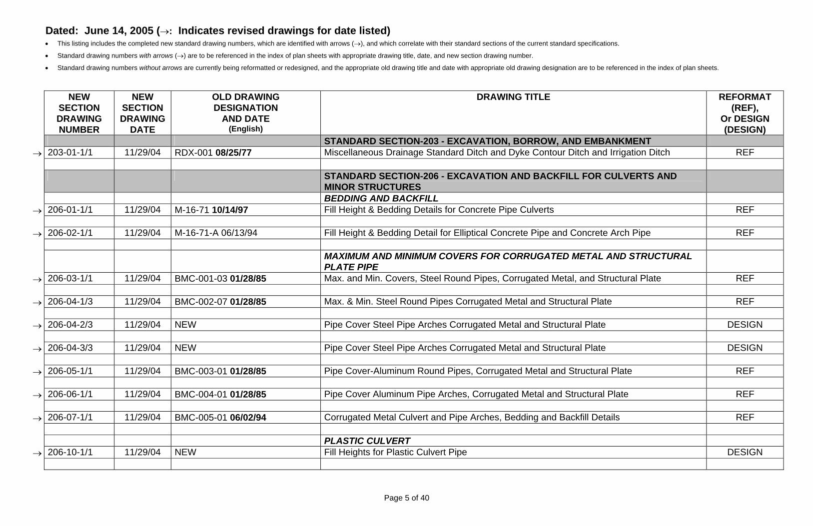
Dated: June 14, 2005 (→: Indicates revised drawings for date listed) • This listing includes the completed new standard drawing numbers, which are identified with arrows (→), and which correlate with their standard sections of the current standard specifications.
• Standard drawing numbers with arrows (→) are to be referenced in the index of plan sheets with appropriate drawing title, date, and new section drawing number.
• Standard drawing numbers without arrows are currently being reformatted or redesigned, and the appropriate old drawing title and date with appropriate old drawing designation are to be referenced in the index of plan sheets.
NEW SECTION DRAWING NUMBER
NEW SECTION DRAWING
DATE
OLD DRAWING DESIGNATION
AND DATE (English)
DRAWING TITLE REFORMAT (REF),
Or DESIGN (DESIGN)
STANDARD SECTION-203 - EXCAVATION, BORROW, AND EMBANKMENT → 203-01-1/1 11/29/04 RDX-001 08/25/77 Miscellaneous Drainage Standard Ditch and Dyke Contour Ditch and Irrigation Ditch REF
STANDARD SECTION-206 - EXCAVATION AND BACKFILL FOR CULVERTS AND
MINOR STRUCTURES
BEDDING AND BACKFILL → 206-01-1/1 11/29/04 M-16-71 10/14/97 Fill Height & Bedding Details for Concrete Pipe Culverts REF
→ 206-02-1/1 11/29/04 M-16-71-A 06/13/94 Fill Height & Bedding Detail for Elliptical Concrete Pipe and Concrete Arch Pipe REF
MAXIMUM AND MINIMUM COVERS FOR CORRUGATED METAL AND STRUCTURAL
PLATE PIPE
→ 206-03-1/1 11/29/04 BMC-001-03 01/28/85 Max. and Min. Covers, Steel Round Pipes, Corrugated Metal, and Structural Plate REF
→ 206-04-1/3 11/29/04 BMC-002-07 01/28/85 Max. & Min. Steel Round Pipes Corrugated Metal and Structural Plate REF
→ 206-04-2/3 11/29/04 NEW Pipe Cover Steel Pipe Arches Corrugated Metal and Structural Plate DESIGN
→ 206-04-3/3 11/29/04 NEW Pipe Cover Steel Pipe Arches Corrugated Metal and Structural Plate DESIGN
→ 206-05-1/1 11/29/04 BMC-003-01 01/28/85 Pipe Cover-Aluminum Round Pipes, Corrugated Metal and Structural Plate REF
→ 206-06-1/1 11/29/04 BMC-004-01 01/28/85 Pipe Cover Aluminum Pipe Arches, Corrugated Metal and Structural Plate REF
→ 206-07-1/1 11/29/04 BMC-005-01 06/02/94 Corrugated Metal Culvert and Pipe Arches, Bedding and Backfill Details REF PLASTIC CULVERT
→ 206-10-1/1 11/29/04 NEW Fill Heights for Plastic Culvert Pipe DESIGN
Page 5 of 40

Dated: June 14, 2005 (→: Indicates revised drawings for date listed) • This listing includes the completed new standard drawing numbers, which are identified with arrows (→), and which correlate with their standard sections of the current standard specifications.
• Standard drawing numbers with arrows (→) are to be referenced in the index of plan sheets with appropriate drawing title, date, and new section drawing number.
• Standard drawing numbers without arrows are currently being reformatted or redesigned, and the appropriate old drawing title and date with appropriate old drawing designation are to be referenced in the index of plan sheets.
NEW SECTION DRAWING NUMBER
NEW SECTION DRAWING
DATE
OLD DRAWING DESIGNATION
AND DATE (English)
DRAWING TITLE REFORMAT (REF),
Or DESIGN (DESIGN)
STANDARD SECTION-210 - EXCAVATION AND BACKFILL FOR MAJOR STRUCTURES
→ 210-01-1/1 11/29/04 BEB-001-04 11/07/80 Excavation and Backfill for Bridges, Walls and CBCs REF STANDARD SECTION-451 - PORTLAND CEMENT CONCRETE PAVEMENT PAVEMENT JOINT DETAILS
→ 451-01-1/2 11/29/04 PJD-001-1/2 01/18/00 PCCP Joint Details REF
→ 451-01-2/2 11/29/04 PJD-001-2/2 01/18/00 PCCP Joint Details REF STANDARD SECTION-511 - CONCRETE STRUCTURES CULVERT HEADWALLS AND ENDWALLS
→ 511-03-1/1 11/29/04 H-1-61 06/10/94 Pipe Culvert Headwalls REF
→ 511-04-1/1 11/29/04 HA-1-63 06/09/94 Pipe Arch Culvert Headwalls DESIGN HA-3-63-1/2 06/09/94 Skewed Metal Pipe Arch Culvert Endwalls HA-3-63-2/2 03/24/64 Skewed Elliptical Concrete Pipe Arch Culvert Endwalls BRIDGE SLOPE PAVEMENT
→ 511-05-1/1 11/29/04 BSP-001-01 06/06/94 Slope Pavement Details at Bridges REF CONCRETE BLANKETS FOR METAL AND PLASTIC CULVERT PIPE
→ 511-11-1/1 11/29/04 BBG-020 11/21/01 Single Metal Pipe Concrete Blanket without Safety Grate (Normal & 5° to 35°Skewed Installations)
REF
→ 511-11A-1/2 03/03/05 NEW Single Pipe Concrete Blanket without Safety Grate HDPE Pipe DESIGN
→ 511-11A-2/2 03/03/05 NEW Single Pipe Concrete Blanket without Safety Grate HDPE Pipe DESIGN
Page 6 of 40

Dated: June 14, 2005 (→: Indicates revised drawings for date listed) • This listing includes the completed new standard drawing numbers, which are identified with arrows (→), and which correlate with their standard sections of the current standard specifications.
• Standard drawing numbers with arrows (→) are to be referenced in the index of plan sheets with appropriate drawing title, date, and new section drawing number.
• Standard drawing numbers without arrows are currently being reformatted or redesigned, and the appropriate old drawing title and date with appropriate old drawing designation are to be referenced in the index of plan sheets.
NEW SECTION DRAWING NUMBER
NEW SECTION DRAWING
DATE
OLD DRAWING DESIGNATION
AND DATE (English)
DRAWING TITLE REFORMAT (REF),
Or DESIGN (DESIGN)
WINGWALLS WITH SAFETY PIPES
→ 511-11B-1/6 11/29/04 DRWG-038-1/4 03/02/94 Wingwalls with Safety Pipes, Normal Skew, 4:1 Embankment Slope REF
→ 511-11B-2/6 11/29/04 DRWG-038-2/4 06/15/94 Wingwalls with Safety Pipes, Normal Skew, 4:1 Embankment Slope REF
→ 511-11B-3/6 11/29/04 NEW Wingwalls with Safety Pipes, Normal Skew, 4:1 Embankment Slope REF
→ 511-11B-4/6 11/29/04 DRWG-038-3/4 03/02/94 Wingwalls with Safety Pipes, Normal Skew, 6:1 Embankment Slope REF
→ 511-11B-5/6 11/29/04 DRWG-038-4/4 06/15/94 Wingwalls with Safety Pipes, Normal Skew, 6:1 Embankment Slope REF
→ 511-11B-6/6 11/29/04 NEW Wingwalls with Safety Pipes, Normal Skew, 6:1 Embankment Slope REF
→ 511-12-1/2 11/29/04 BBG-021 11/21/01 Multiple Metal Pipe Concrete Blanket without Safety Grate (Normal & 5° to 35°Skewed) REF
→ 511-12-2/2 11/29/04 NEW Multiple Metal Pipe Concrete Blanket without Safety Grate (Normal & 5° to 35°Skewed) REF
→ 511-12A-1/2 03/03/05 NEW Multiple Pipe Concrete Blanket without Safety Grate – HDPE Pipe (Normal & 5° to 35°Skewed Installations)
DESIGN
→ 511-12A-2/2 03/03/05 NEW Multiple Pipe Concrete Blanket without Safety Grate – HDPE Pipe (Normal & 5° to
35°Skewed Installations) DESIGN
→ 511-13-1/2 11/29/04 BBG-022 11/21/01 Single Metal Pipe Concrete Blanket, With Safety Grate (Normal & 5° to 35° Skewed) REF
→ 511-13-2/2 11/29/04 NEW Single Metal Pipe Concrete Blanket, With Safety Grate (Normal & 5° to 35° Skewed) REF
→ 511-13A-1/3 03/03/05 NEW Single Pipe Concrete Blanket with Safety Grate – HDPE Pipe (Normal & 5° to 35° Skewed
Installations) DESIGN
Page 7 of 40

Dated: June 14, 2005 (→: Indicates revised drawings for date listed) • This listing includes the completed new standard drawing numbers, which are identified with arrows (→), and which correlate with their standard sections of the current standard specifications.
• Standard drawing numbers with arrows (→) are to be referenced in the index of plan sheets with appropriate drawing title, date, and new section drawing number.
• Standard drawing numbers without arrows are currently being reformatted or redesigned, and the appropriate old drawing title and date with appropriate old drawing designation are to be referenced in the index of plan sheets.
NEW SECTION DRAWING NUMBER
NEW SECTION DRAWING
DATE
OLD DRAWING DESIGNATION
AND DATE (English)
DRAWING TITLE REFORMAT (REF),
Or DESIGN (DESIGN)
→ 511-13A-2/3 03/03/05 NEW Single Pipe Concrete Blanket with Safety Grate – HDPE Pipe (Normal & 5° to 35° Skewed
Installations) DESIGN
→ 511-13A-3/3 03/03/05 NEW Single Pipe Concrete Blanket with Safety Grate – HDPE Pipe (Normal & 5° to 35° Skewed
Installations) DESIGN
→ 511-14-1/2 11/29/04 BBG-023 11/21/01 Multiple Metal Pipe Concrete Blanket With Safety Grate (Normal & 5° to 35° Skewed) REF
→ 511-14-2/2 11/29/04 NEW Multiple Metal Pipe Concrete Blanket With Safety Grate (Normal & 5° to 35° Skewed) REF
→ 511-14A-1/3 03/03/05 NEW Multiple Pipe Concrete Blanket With Safety Grate – HDPE Pipe (Normal & 5° to 35°
Skewed Installations) DESIGN
→ 511-14A-2/3 03/03/05 NEW Multiple Pipe Concrete Blanket With Safety Grate – HDPE Pipe (Normal & 5° to 35°
Skewed Installations) DESIGN
→ 511-14A-3/3 03/03/05 NEW Multiple Pipe Concrete Blanket With Safety Grate – HDPE Pipe (Normal & 5° to 35°
Skewed Installations) DESIGN
→ 511-15-1/2 11/29/04 BBG-024 11/21/01 Typical Concrete Blanket Details REF
→ 511-15-2/2 11/29/04 NEW Typical Concrete Blanket Details REF
→ 511-15A-1/2 03/03/05 NEW Typical Concrete Blanket Details HDPE Pipe DESIGN
→ 511-15A-2/2 03/03/05 NEW Typical Concrete Blanket Details HDPE Pipe DESIGN
→ 511-16-1/1 11/29/04 BBG-025 11/21/01 Concrete Blanket Safety Grate Details for Circular Metal Pipes (Normal & 5° Skewed) REF
Page 8 of 40

Dated: June 14, 2005 (→: Indicates revised drawings for date listed) • This listing includes the completed new standard drawing numbers, which are identified with arrows (→), and which correlate with their standard sections of the current standard specifications.
• Standard drawing numbers with arrows (→) are to be referenced in the index of plan sheets with appropriate drawing title, date, and new section drawing number.
• Standard drawing numbers without arrows are currently being reformatted or redesigned, and the appropriate old drawing title and date with appropriate old drawing designation are to be referenced in the index of plan sheets.
NEW SECTION DRAWING NUMBER
NEW SECTION DRAWING
DATE
OLD DRAWING DESIGNATION
AND DATE (English)
DRAWING TITLE REFORMAT (REF),
Or DESIGN (DESIGN)
→ 511-16A-1/2 03/03/05 NEW Single Pipe Concrete Blanket with Safety Grate for HDPE Circular Pipes DESIGN
→ 511-16A-2/2 03/03/05 NEW Single Pipe Concrete Blanket with Safety Grate for HDPE Circular Pipes DESIGN
→ 511-17-1/1 11/29/04 BBG-026 11/21/01 Concrete Blanket, Safety Grate Details for Circular Metal Pipes (10° & 15° Skewed Installations)
REF
→ 511-17A-1/2 03/03/05 NEW Typical Concrete Blanket Details for Parallel HDPE Culvert Drain DESIGN
→ 511-17A-2/2 03/03/05 NEW Typical Concrete Blanket Details for Parallel HDPE Culvert Drain DESIGN
→ 511-18-1/1 11/29/04 BBG-027 11/21/01 Concrete Blankets, Safety Grate Details for Circular Metal Pipes (20° & 25° Skewed) REF
→ 511-19-1/1 11/24/04 BBG-028 11/21/01 Concrete Blankets Safety Grate Details for Circular Metal Pipes (30° & 35° Skewed) REF
→ 511-20-1/2 11/29/04 BBG-029 11/21/01 Single Pipe Concrete Blanket with Safety Grate for Circular Metal Pipe (40° Skew or
Greater) REF
→ 511-20-2/2 11/29/04 NEW Concrete Blanket Safety Grate Details for Circular Metal Pipes (40° Skew or Greater) REF
→ 511-21-1/1 11/29/04 BBG-030 11/21/01 Typical Concrete Blanket Details for 40° Skew and Greater REF
→ 511-22-1/2 11/29/04 BBG-031 04/02/02 Single Pipe Concrete Blanket with Safety Grate for Circular Metal Pipes (Parallel to CL
Roadway) REF
→ 511-22-2/2 11/29/04 NEW Single Pipe Concrete Blanket with Safety Grate for Circular Metal Pipes (Parallel to CL
Roadway) REF
→ 511-23-1/2 11/29/04 BBG-032 04/02/02 Single Pipe Concrete Blanket with Safety Grate for Metal Pipe Arches (Parallel to CL
Roadway) REF
Page 9 of 40

Dated: June 14, 2005 (→: Indicates revised drawings for date listed) • This listing includes the completed new standard drawing numbers, which are identified with arrows (→), and which correlate with their standard sections of the current standard specifications.
• Standard drawing numbers with arrows (→) are to be referenced in the index of plan sheets with appropriate drawing title, date, and new section drawing number.
• Standard drawing numbers without arrows are currently being reformatted or redesigned, and the appropriate old drawing title and date with appropriate old drawing designation are to be referenced in the index of plan sheets.
NEW SECTION DRAWING NUMBER
NEW SECTION DRAWING
DATE
OLD DRAWING DESIGNATION
AND DATE (English)
DRAWING TITLE REFORMAT (REF),
Or DESIGN (DESIGN)
→ 511-23-2/2 11/29/04 NEW Single Pipe Concrete Blanket with Safety Grate for Metal Pipe Arches (Parallel to CL Roadway)
REF
→ 511-24-1/1 11/29/04 BBG-033 04/02/02 Typical Concrete Blanket Details For Parallel Culvert Drain REF
→ 511-25-1/2 11/29/04 BBG-040 07/17/00 Single Culvert Metal Pipe Concrete Headwall & Apron 60” – 120” Diameter Pipe (Normal) REF
→ 511-25-2/2 11/29/04 NEW Single Culvert Metal Pipe Concrete Headwall & Apron 60” – 120” Diameter Pipe (Normal) REF
→ 511-26-1/2 11/29/04 BBG-041 07/17/00 Single Culvert Metal Pipe Concrete Headwall & Apron 60” – 120” Diameter Pipe (Skewed) REF
→ 511-26-2/2 11/29/04 NEW Single Culvert Metal Pipe Concrete Headwall & Apron 60” – 120” Diameter Pipe (Skewed) REF
→ 511-27-1/2 11/29/04 BBG-042 07/17/00 Double Culvert Metal Pipe Concrete Headwall & Apron 60 “ – 120” Dia. Pipe (Normal) REF
→ 511-27-2/2 11/29/04 NEW Double Culvert Metal Pipe Concrete Headwall & Apron 60” – 120” Pipe (Normal) REF
→ 511-28-1/2 11/29/04 BBG-043 07/17/00 Double Culvert Metal Pipe Concrete Headwall and Apron 60” to 120” φ Pipe (Skewed) REF
→ 511-28-2/2 11/29/04 NEW Double Culvert Metal Pipe Concrete Headwall and Apron 60” to 120” φ Pipe (Skewed) REF
→ 511-29-1/2 11/29/04 BBG-044 07/17/00 Triple Culvert Metal Pipe Concrete Headwall and Apron 60” to 120” φ Pipe (Normal) REF
→ 511-29-2/2 11/29/04 NEW Triple Culvert Metal Pipe Concrete Headwall and Apron 60” to 120” φ Pipe (Normal) REF
→ 511-30-1/2 11/29/04 BBG-045 07/17/00 Triple Culvert Metal Pipe Concrete Headwall and Apron (60” to 120” φ Pipe) (Skewed) REF
→ 511-30-2/2 11/29/04 NEW Triple Culvert Metal Pipe Concrete Headwall and Apron 60” to 120” φ Pipe (Skewed) REF
Page 10 of 40

Dated: June 14, 2005 (→: Indicates revised drawings for date listed) • This listing includes the completed new standard drawing numbers, which are identified with arrows (→), and which correlate with their standard sections of the current standard specifications.
• Standard drawing numbers with arrows (→) are to be referenced in the index of plan sheets with appropriate drawing title, date, and new section drawing number.
• Standard drawing numbers without arrows are currently being reformatted or redesigned, and the appropriate old drawing title and date with appropriate old drawing designation are to be referenced in the index of plan sheets.
NEW SECTION DRAWING NUMBER
NEW SECTION DRAWING
DATE
OLD DRAWING DESIGNATION
AND DATE (English)
DRAWING TITLE REFORMAT (REF),
Or DESIGN (DESIGN)
→ 511-31-1/2 11/29/04 BBG-050 02/27/03 Single Arched Metal Pipe Concrete Blanket Without Safety Grate (Normal and 5° to 35° Skewed)
REF
→ 511-31-2/2 11/29/04 NEW Single Arched Metal Pipe Concrete Blanket Without Safety Grate (Normal and 5° to 35°
Skewed) REF
→ 511-32-1/2 11/29/04 BBG-051 02/27/03 Multiple Arched Metal Pipe Concrete Blanket Without Safety Grate (Normal and 5° to 35°
Skewed) REF
→ 511-32-2/2 11/29/04 NEW Multiple Arched Metal Pipe Concrete Blanket Without Safety Grate (Normal and 5° to 35°
Skewed) REF
→ 511-33-1/2 11/29/04 BBG-052 02/27/03 Single Arched Metal Pipe Concrete Blanket With Safety Grate (Normal and 5° to 35°
Skewed) REF
→ 511-33-2/2 11/29/04 NEW Single Arched Metal Pipe Concrete Blanket With Safety Grate (Normal and 5° to 35°
Skewed) REF
→ 511-34-1/2 11/29/04 BBG-053 02/27/03 Multiple Arched Metal Pipes Concrete Blanket With Safety Grate (Normal and 5° to 35°
Skewed) REF
→ 511-34-2/2 11/29/04 NEW Multiple Arched Metal Pipes Concrete Blanket With Safety Grate (Normal and 5° to 35°
Skewed) REF
→ 511-35-1/2 11/29/04 BBG-054 02/27/03 Typical Concrete Blanket Details REF
→ 511-35-2/2 11/29/04 NEW Typical Concrete Blanket Details REF
→ 511-36-1/1 11/29/04 BBG-055 02/27/03 Concrete Blankets Safety Grate Details For Arched Metal Pipes (Normal and 5° Thru 15°
Skewed) REF
Page 11 of 40

Dated: June 14, 2005 (→: Indicates revised drawings for date listed) • This listing includes the completed new standard drawing numbers, which are identified with arrows (→), and which correlate with their standard sections of the current standard specifications.
• Standard drawing numbers with arrows (→) are to be referenced in the index of plan sheets with appropriate drawing title, date, and new section drawing number.
• Standard drawing numbers without arrows are currently being reformatted or redesigned, and the appropriate old drawing title and date with appropriate old drawing designation are to be referenced in the index of plan sheets.
NEW SECTION DRAWING NUMBER
NEW SECTION DRAWING
DATE
OLD DRAWING DESIGNATION
AND DATE (English)
DRAWING TITLE REFORMAT (REF),
Or DESIGN (DESIGN)
→ 511-37-1/1 11/29/04 BBG-056 02/27/03 Concrete Blankets Safety Grate Details for Arched Metal Pipes (Normal and 20° Thru 35° Skewed)
REF
→ 511-38-1/2 11/29/04 BBG-057 02/27/03 Single Metal Pipe Concrete Blanket With Safety Grate for Arched Pipes (40° Skew or
Greater) REF
→ 511-38-2/2 11/29/04 NEW Single Metal Pipe Concrete blanket With Safety Grate for Arched Pipes (40° Skew or
Greater) REF
→ 511-39-1/1 11/29/04 BBG-058 02/27/03 Typical Concrete Blanket Details for 40° Skew and Greater REF
→ 511-40-1/2 11/29/04 BBG-059 02/27/03 Single Arched Metal Pipe Concrete Blanket With Safety Grate (Parallel to CL Roadway) REF
→ 511-40-2/2 11/29/04 NEW Single Arched Metal Pipe Concrete Blanket With Safety Grate (Parallel to CL Roadway) REF
→ 511-41-1/1 11/29/04 BBG-060 02/27/03 Typical Concrete Blanket Details for Parallel Culvert Drain REF
BARRIER POST ANCHORAGE BLOCK
→ 511-54-1/2 11/29/04 BPAB-001 06/02/94 Barrier Post Anchorage Block for New and Existing CBC Construction REF
→ 511-54-2/2 11/29/04 BPAB-002 08/19/88 Barrier Post Anchorage Block for Existing and New CBC Construction REF CONCRETE BOX CULVERTS CB-31-1/4 06/06/94 Concrete Box Culvert Barrels Single Opening-Normal Design No. 1, 0- 5’ Cover CB-31-2/4 06/06/94 Concrete Box Culvert Barrels Single Opening-Normal Design No. 2, 5’-10’ Cover CB-31-3/4 06/06/94 Concrete Box Culvert Barrels Single Opening-Normal Design No. 3, 10’-15’ Cover CB-31-4/4 06/06/94 Concrete Box Culvert Barrels Single Opening-Normal Design No. 4, 15’-20’ Cover
Page 12 of 40

Dated: June 14, 2005 (→: Indicates revised drawings for date listed) • This listing includes the completed new standard drawing numbers, which are identified with arrows (→), and which correlate with their standard sections of the current standard specifications.
• Standard drawing numbers with arrows (→) are to be referenced in the index of plan sheets with appropriate drawing title, date, and new section drawing number.
• Standard drawing numbers without arrows are currently being reformatted or redesigned, and the appropriate old drawing title and date with appropriate old drawing designation are to be referenced in the index of plan sheets.
NEW SECTION DRAWING NUMBER
NEW SECTION DRAWING
DATE
OLD DRAWING DESIGNATION
AND DATE (English)
DRAWING TITLE REFORMAT (REF),
Or DESIGN (DESIGN)
CB-31-S 08/02/93 Concrete Box Culvert Barrels Single Opening Skew CB-31-7 06/07/94 Concrete Box Culvert Barrels Single Opening 7’ x 7’ All Designs Normal And Skew CB-32-1/5 06/07/94 Concrete Box Culvert Barrels Double Opening-Normal All Designs General Data CB-32-2/5 08/02/93 Concrete Box Culvert Barrels Double Opening-Normal Design No.1 CB-32-3/5 08/02/93 Concrete Box Culvert Barrels Double Opening-Normal Design No.2 CB-32-4/5 08/02/93 Concrete Box Culvert Barrels Double Opening-Normal Design No.3 CB-32-5/5 08/02/93 Concrete Box Culvert Barrels Double Opening-Normal Design No.4 CB-32-7 06/06/94 Concrete Box Culvert Barrels Double Opening 7’ X 7’ CB-32-15-1/2 06/17/94 Concrete Box Culvert Barrels Double Opening 15° Skew Design No. 1 and 2 CB-32-15-2/2 06/17/94 Concrete Box Culvert Barrels Double Opening 15° Skew Design No. 3 and 4 CB-32-30-1/2 02/22/94 Concrete Box Culvert Barrels Double Opening 30° Skew Design No. 1 and 2 CB-32-30-2/2 02/22/94 Concrete Box Culvert Barrels Double Opening 30° Skew Design No. 3 and 4 CB-32-45-1/2 06/17/94 Concrete Box Culvert Barrels Double Opening 45° Skew Design No. 1 and 2 CB-32-45-2/2 06/17/94 Concrete Box Culvert Barrels Double Opening 45° Skew Design No .3 and 4 CB-33-1/5 06/08/94 Concrete Box Culvert Barrels Triple Opening-Normal All Designs General Data CB-33-2/5 02/22/94 Concrete Box Culvert Barrels Triple Opening-Normal Design No.1, 0-5’ Cover
Page 13 of 40

Dated: June 14, 2005 (→: Indicates revised drawings for date listed) • This listing includes the completed new standard drawing numbers, which are identified with arrows (→), and which correlate with their standard sections of the current standard specifications.
• Standard drawing numbers with arrows (→) are to be referenced in the index of plan sheets with appropriate drawing title, date, and new section drawing number.
• Standard drawing numbers without arrows are currently being reformatted or redesigned, and the appropriate old drawing title and date with appropriate old drawing designation are to be referenced in the index of plan sheets.
NEW SECTION DRAWING NUMBER
NEW SECTION DRAWING
DATE
OLD DRAWING DESIGNATION
AND DATE (English)
DRAWING TITLE REFORMAT (REF),
Or DESIGN (DESIGN)
CB-33-3/5 02/22/94 Concrete Box Culvert Barrels Triple Opening-Normal Design No.2, 5’-10’ Cover CB-33-4/5 02/22/94 Concrete Box Culvert Barrels Triple Opening-Normal Design No.3, 10’-15’ Cover CB-33-5/5 02/22/94 Concrete Box Culvert Barrels Triple Opening-Normal Design No.4, 15’-20’ Cover CB-33-15-1/2 06/17/94 Concrete Box Culvert Barrels Triple Opening 15° Skew Design No. 1 and 2 CB-33-15-2/2 06/17/94 Concrete Box Culvert Barrels Triple Opening 15° Skew Design No. 3 and 4 CB-33-30-1/2 03/09/98 Concrete Box Culvert Barrels Triple Opening 30° Skew Design No. 1 and 2 CB-33-30-2/2 06/15/94 Concrete Box Culvert Barrels Triple Opening 30° Skew Design No. 3 and 4 CB-33-45-1/2 06/17/94 Concrete Box Culvert Barrels Triple Opening 45° Skew Design No. 1 and 2 CB-33-45-2/2 06/17/94 Concrete Box Culvert Barrels Triple Opening 45° Skew Design No .3 and 4 CB-34-1/5 06/08/94 Concrete Box Culvert Barrels Quadruple Opening-Normal All Designs General Data CB-34-2/5 02/22/94 Concrete Box Culvert Barrels Quadruple Opening-Normal Design No.1, 0 to 5’ Cover CB-34-3/5 02/22/94 Concrete Box Culvert Barrels Quadruple Opening-Normal Design No.2, 5’-10’ Cover CB-34-4/5 02/22/94 Concrete Box Culvert Barrels Quadruple Opening-Normal Design No.3, 10’-15’ Cover CB-34-5/5 02/22/94 Concrete Box Culvert Barrels Quadruple Opening-Normal Design No.4, 15’-20’ Cover CB-34-15-1/2 06/17/94 Concrete Box Culvert Barrels Quadruple Opening-15° Skew Design No. 1 and 2
Page 14 of 40

Dated: June 14, 2005 (→: Indicates revised drawings for date listed) • This listing includes the completed new standard drawing numbers, which are identified with arrows (→), and which correlate with their standard sections of the current standard specifications.
• Standard drawing numbers with arrows (→) are to be referenced in the index of plan sheets with appropriate drawing title, date, and new section drawing number.
• Standard drawing numbers without arrows are currently being reformatted or redesigned, and the appropriate old drawing title and date with appropriate old drawing designation are to be referenced in the index of plan sheets.
NEW SECTION DRAWING NUMBER
NEW SECTION
OLD DRAWING DESIGNATION
AND DATE (English)
DRAWING TITLE REFORMAT (REF),
Or DESIGN (DESIGN)
DRAWING DATE
CB-34-15-2/2 06/17/94 Concrete Box Culvert Barrels Quadruple Opening 15° Skew Design No. 3 and 4 CB-34-30-1/2 06/17/94 Concrete Box Culvert Barrels Quadruple Opening 30° Skew Design No. 1 and 2 CB-34-30-2/2 06/17/94 Concrete Box Culvert Barrels Quadruple Opening 30° Skew Design No. 3 and 4 CB-34-45-1/2 06/17/94 Concrete Box Culvert Barrels Quadruple Opening 45° Skew Design No. 1 and 2 CB-34-45-2/2 06/17/94 Concrete Box Culvert Barrels Quadruple Opening 45° Skew Design No. 3 and 4 CB-35-1/5 06/08/94 Concrete Box Culvert Barrels Quintuple Opening-Normal All Designs General Data CB-35-2/5 02/22/94 Concrete Box Culvert Barrels Quintuple Opening-Normal Design No.1, 0-5’ Cover CB-35-3/5 02/22/94 Concrete Box Culvert Barrels Quintuple Opening-Normal Design No.2, 5’-10’ Cover CB-35-4/5 02/22/94 Concrete Box Culvert Barrels Quintuple Opening-Normal Design No.3, 10’-15’ Cover CB-35-5/5 02/22/94 Concrete Box Culvert Barrels Quintuple Opening-Normal Design No.4, 15’-20’ Cover CB-35-15-1/2 06/17/94 Concrete Box Culvert Barrels Quintuple Opening 15° Skew Design No. 1 and 2 CB-35-15-2/2 06/17/94 Concrete Box Culvert Barrels Quintuple Opening 15° Skew Design No. 3 and 4 CB-35-30-1/2 06/17/94 Concrete Box Culvert Barrels Quintuple Opening 30° Skew Design No. 1 and 2 CB-35-30-2/2 06/17/94 Concrete Box Culvert Barrels Quintuple Opening 30° Skew Design No. 3 and 4 CB-35-45-1/2 06/17/94 Concrete Box Culvert Barrels Quintuple Opening 45° Skew Design No. 1 and 2 CB-35-45-2/2 06/17/94 Concrete Box Culvert Barrels Quintuple Opening 45° Skew Design No. 3 and 4
Page 15 of 40

Dated: June 14, 2005 (→: Indicates revised drawings for date listed) • This listing includes the completed new standard drawing numbers, which are identified with arrows (→), and which correlate with their standard sections of the current standard specifications.
• Standard drawing numbers with arrows (→) are to be referenced in the index of plan sheets with appropriate drawing title, date, and new section drawing number.
• Standard drawing numbers without arrows are currently being reformatted or redesigned, and the appropriate old drawing title and date with appropriate old drawing designation are to be referenced in the index of plan sheets.
NEW SECTION DRAWING NUMBER
NEW SECTION
OLD DRAWING DESIGNATION
AND DATE (English)
DRAWING TITLE REFORMAT (REF),
Or DESIGN (DESIGN)
DRAWING DATE
BCE-001 11/25/92 Concrete Box and Culvert Extension CONCRETE BOX CULVERT / WINGWALLS WSP-0-1/2 12/15/89 Wingwalls for Normal Concrete Box Culverts WSP-0-2/2 06/14/94 Wingwalls for normal concrete box culverts WSP-15-1/2 12/15/89 Wingwalls for 15° skew concrete box culverts WSP-15-2/2 06/14/94 Wingwalls for 15° skew concrete box culverts NO IMPERIAL DWG Wingwalls for 15° skew concrete box culverts WSP-30-1/2 12/15/89 Wingwalls for 30° skew concrete box culverts WSP-30-2/2 06/14/94 Wingwalls for 30° skew concrete box culverts NO IMPERIAL DWG Wingwalls for 30° skew concrete box culverts WSP-45-1/3 12/15/89 Wingwalls for 45° skew concrete box culverts WSP-45-2/3 12/15/89 Wingwalls for 45° skew concrete box culverts WSP-45-3/3 06/14/94 Wingwalls for 45° skew concrete box culverts DRAWING–028 1/2 06/15/94 Special Design Parapet & Cutoff Wall for Attaching 20 Series CBC to WCB Series
Wingwalls (Normal & Skewed Structures)
DRAWING-028-2/2 06/15/94 Special Design Parapet & Cutoff Wall for attaching 20 Series CBC to WCB Series
Wingwalls (Normal & Skewed Structures)
Page 16 of 40

Dated: June 14, 2005 (→: Indicates revised drawings for date listed) • This listing includes the completed new standard drawing numbers, which are identified with arrows (→), and which correlate with their standard sections of the current standard specifications.
• Standard drawing numbers with arrows (→) are to be referenced in the index of plan sheets with appropriate drawing title, date, and new section drawing number.
• Standard drawing numbers without arrows are currently being reformatted or redesigned, and the appropriate old drawing title and date with appropriate old drawing designation are to be referenced in the index of plan sheets.
NEW SECTION DRAWING NUMBER
NEW SECTION
OLD DRAWING DESIGNATION
AND DATE (English)
DRAWING TITLE REFORMAT (REF),
Or DESIGN (DESIGN)
DRAWING DATE
CB-SP-75 06/07/94 Detail for Special Endwall for CBC with Minimum Cover CATTLE PASSES
→ 511-01-1/2 6/13/05 BCPO-001-04 06/02/94 Details of Median Opening for Single Opening Concrete Box Culvert Cattle Pass REF
→ 511-01-2/2 6/13/05 BCPO-002-02 05/25/81 Details of Median Opening for Single Opening Concrete Box Culvert Cattle Pass REF STANDARD SECTION-514 - CONCRETE BARRIER RAILINGS FOR BRIDGES 32" SINGLE SLOPE BRIDGE BARRIER RAILING
→ 514-01-1/5 11/29/04 BBR-32-1/5 02/19/02REF 32 In. Bridge Barrier Railing General Details (For single-slope barrier installations) REF
→ 514-01-2/5 11/29/04 BBR-32-2/5 02/19/02 32 In. Bridge Barrier Railing Standard Section and Details (For single-slope barrier installations)
REF
→ 514-01-3/5 11/29/04 BBR-32-3/5 02/19/02 32 In. Bridge Barrier Railing Transition Section Details (For single-slope barrier installations) REF
→ 514-01-4/5 11/29/04 BBR-32-4/5 02/19/02 32 In. Bridge Barrier Railing Details at Joint Seals (For single-slope barrier installations) REF
→ 514-01-5/5 11/29/04 BBR-32-5/5 02/19/02 32 In. Dowel Assembly for Expansion Joints in concrete Wall Barrier & Conc. Wall Barrier
Railing (For single-slope barrier installations) REF
32" JERSEY TYPE BRIDGE BARRIER RAILING BBR-001 05/09/95 Barrier Railing General Details (32”Jersey type installations) BBR-002 02/06/92 Barrier Railing Standard Section and Details (32” Jersey type installations) BBR-003 06/03/96 Barrier Railing Transition Section Details (32” Jersey type installations) BBR-004 02/06/92 Barrier Railing Details at Joint Seals (32” Jersey type installations)
Page 17 of 40

Dated: June 14, 2005 (→: Indicates revised drawings for date listed) • This listing includes the completed new standard drawing numbers, which are identified with arrows (→), and which correlate with their standard sections of the current standard specifications.
• Standard drawing numbers with arrows (→) are to be referenced in the index of plan sheets with appropriate drawing title, date, and new section drawing number.
• Standard drawing numbers without arrows are currently being reformatted or redesigned, and the appropriate old drawing title and date with appropriate old drawing designation are to be referenced in the index of plan sheets.
NEW SECTION DRAWING NUMBER
NEW SECTION
OLD DRAWING DESIGNATION
AND DATE (English)
DRAWING TITLE REFORMAT (REF),
Or DESIGN (DESIGN)
DRAWING DATE
BBR-005 05/09/95 Dowel Assembly Details for Expansion Joints Concrete Barrier Railing (32” Jersey type installations)
40" JERSEY TYPE BRIDGE BARRIER RAILING DRAWING 040-1/5 06/30/95 40 In. barrier railing General Details (For Jersey type barrier installations) DRAWING 040-2/5 06/30/95 40 In. Barrier Railing Standard Section Details (For Jersey type barrier installations) DRAWING 040-3/5 06/03/96 40 In. Barrier Railing Transition Section Details (For Jersey type barrier installations) DRAWING 040-4/5 06/30/95 40 In. Barrier Railing Details at Joint Seals (For Jersey type barrier installations) DRAWING 040-5/5 06/30/95 Dowel Assembly Details for Expansion Joints 40” Barrier Railing (For Jersey type barrier
installations)
42" SINGLE SLOPE BRIDGE BARRIER RAILING
→ 514-03-1/5 11/29/04 BBR-42-1/5 02/19/02 42 In. Bridge Barrier Railing General Details (For single-slope barrier installations) REF
→ 514-03-2/5 11/29/04 BBR-42-2/5 02/19/02 42 In. Bridge Barrier Railing Standard Section and Details (For single-slope barrier installations)
REF
→ 514-03-3/5 11/29/04 BBR-42-3/5 02/19/02 42 In. Concrete Bridge Barrier Railing Transition Section Details (For single-slope barrier
installations) REF
→ 514-03-4/5 11/29/04 BBR-42-4/5 02/19/02 42 In. Concrete Bridge Barrier Railing Details at Joint Seals (For single-slope barrier
installations) REF
→ 514-03-5/5 11/29/04 BBR-42-5/5 02/19/02 42 In. Dowel Assembly for expansion Joints in Concrete Wall Barrier & Concrete Barrier
Railing (For single-slope barrier installations) REF
48" JERSEY TYPE BRIDGE BARRIER RAILING
Page 18 of 40

Dated: June 14, 2005 (→: Indicates revised drawings for date listed) • This listing includes the completed new standard drawing numbers, which are identified with arrows (→), and which correlate with their standard sections of the current standard specifications.
• Standard drawing numbers with arrows (→) are to be referenced in the index of plan sheets with appropriate drawing title, date, and new section drawing number.
• Standard drawing numbers without arrows are currently being reformatted or redesigned, and the appropriate old drawing title and date with appropriate old drawing designation are to be referenced in the index of plan sheets.
NEW SECTION DRAWING NUMBER
NEW SECTION
OLD DRAWING DESIGNATION
AND DATE (English)
DRAWING TITLE REFORMAT (REF),
Or DESIGN (DESIGN)
DRAWING DATE
DRAWING 048 1/5 06/30/95 48” Barrier Railing General Details (For Jersey type barrier installations) DRAWING 048 2/5 06/30/95 48” Barrier Railing Standard Section Details (For Jersey type barrier installations) DRAWING 048 3/5 06/03/96 48” Barrier Railing Transition Section Details (For Jersey type barrier installations) DRAWING 048 4/5 06/30/95 48” Barrier Railing Details at Joint Seals (For Jersey type barrier installations) DRAWING 048 5/5 06/30/95 Dowel Assembly Details for Expansion Joints 48” Concrete Barrier Railing STANDARD SECTION-515 - REINFORCED CONCRETE FOR MINOR STRUCTURES CONCRETE BOX CULVERT / CULVERT PIPE
→ 515-01-1/2 11/29/04 DRAWING 039 1/2 04/28/95 Concrete Collars & Plugs for CBC to Metal Culvert Pipe REF
→ 515-01-2/2 11/29/04 DRAWING 039-2/2 02/01/95 Cast-in-Place, Precast, & Prefabricated Connectors for Culverts REF BRIDGE RUNDOWNS
→ 515-02-1/2 11/29/04 DRAWING 042-1/3 10/24/94 Rundown Flume Type I For Modified or Pinned Curb With Half pipe Rundown REF
→ 515-02-2/2 11/29/04 NEW Alternate Rundowns For Rundown Flumes Type I, II, and III Full Pipe, Concrete And Riprap DESIGN
→ 515-03-1/1 11/29/04 DRAWING 042-2/3 10/24/94 Rundown Flume Type II (Sag) For Modified Or Pinned Curb REF
→ 515-04-1/2 04/25/05 DRWG-042-3/3 10/24/94 Rundown Flume Type III For Bridges DESIGN
→ 515-04-2/2 04/25/05 NEW Drop Inlet with full Pipe Rundown for CWB, Modified, or Pinned Curb DESIGN ROADSIDE RUNDOWNS
→ 515-05-1/3 11/29/04 NEW Drop Inlet With Full Pipe Rundown Type I For Roadside Ditch DESIGN
→ 515-05-2/3 11/29/04 NEW Headwall With Full Pipe Rundown Type II For Roadside Ditch DESIGN
Page 19 of 40
Dated: June 14, 2005 (→: Indicates revised drawings for date listed) • This listing includes the completed new standard drawing numbers, which are identified with arrows (→), and which correlate with their standard sections of the current standard specifications.
• Standard drawing numbers with arrows (→) are to be referenced in the index of plan sheets with appropriate drawing title, date, and new section drawing number.
• Standard drawing numbers without arrows are currently being reformatted or redesigned, and the appropriate old drawing title and date with appropriate old drawing designation are to be referenced in the index of plan sheets.
NEW SECTION DRAWING NUMBER
NEW SECTION
OLD DRAWING DESIGNATION
AND DATE (English)
DRAWING TITLE REFORMAT (REF),
Or DESIGN (DESIGN)
DRAWING DATE
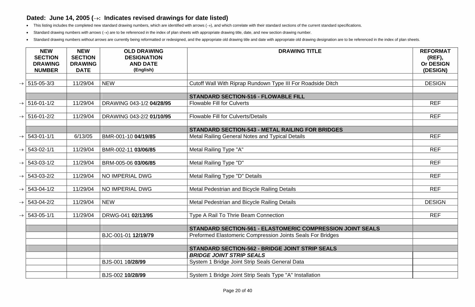
→ 515-05-3/3 11/29/04 NEW Cutoff Wall With Riprap Rundown Type III For Roadside Ditch DESIGN
STANDARD SECTION-516 - FLOWABLE FILL
→ 516-01-1/2 11/29/04 DRAWING 043-1/2 04/28/95 Flowable Fill for Culverts REF
→ 516-01-2/2 11/29/04 DRAWING 043-2/2 01/10/95 Flowable Fill for Culverts/Details REF STANDARD SECTION-543 - METAL RAILING FOR BRIDGES
→ 543-01-1/1 6/13/05 BMR-001-10 04/19/85 Metal Railing General Notes and Typical Details REF
→ 543-02-1/1 11/29/04 BMR-002-11 03/06/85 Metal Railing Type "A" REF
→ 543-03-1/2 11/29/04 BRM-005-06 03/06/85 Metal Railing Type "D" REF
→ 543-03-2/2 11/29/04 NO IMPERIAL DWG Metal Railing Type "D" Details REF
→ 543-04-1/2 11/29/04 NO IMPERIAL DWG Metal Pedestrian and Bicycle Railing Details REF
→ 543-04-2/2 11/29/04 NEW Metal Pedestrian and Bicycle Railing Details DESIGN
→ 543-05-1/1 11/29/04 DRWG-041 02/13/95 Type A Rail To Thrie Beam Connection REF STANDARD SECTION-561 - ELASTOMERIC COMPRESSION JOINT SEALS BJC-001-01 12/19/79 Preformed Elastomeric Compression Joints Seals For Bridges STANDARD SECTION-562 - BRIDGE JOINT STRIP SEALS BRIDGE JOINT STRIP SEALS BJS-001 10/28/99 System 1 Bridge Joint Strip Seals General Data BJS-002 10/28/99 System 1 Bridge Joint Strip Seals Type "A" Installation
Page 20 of 40

Dated: June 14, 2005 (→: Indicates revised drawings for date listed) • This listing includes the completed new standard drawing numbers, which are identified with arrows (→), and which correlate with their standard sections of the current standard specifications.
• Standard drawing numbers with arrows (→) are to be referenced in the index of plan sheets with appropriate drawing title, date, and new section drawing number.
• Standard drawing numbers without arrows are currently being reformatted or redesigned, and the appropriate old drawing title and date with appropriate old drawing designation are to be referenced in the index of plan sheets.
NEW SECTION DRAWING NUMBER
NEW SECTION
OLD DRAWING DESIGNATION
AND DATE (English)
DRAWING TITLE REFORMAT (REF),
Or DESIGN (DESIGN)
DRAWING DATE
BJS-003 10/28/99 System 1 Bridge Joint Strip Seals Type "B" Installation INFLATABLE BRIDGE JOINT SEALS DRAWING 056 11/05/96 Inflatable Bridge Joint Seals System 3 ASPHALT PLUG BRIDGE JOINT SEALS DRAWING 057 11/05/96 Asphalt Plug Bridge Joint Seals System 4 STANDARD SECTION-563 - POLYMER BRIDGE JOINT STRIP SEALS DRAWING 055 11/05/96 Polymer Bridge Joint Seals System 2 STANDARD SECTION-570 - PIPE CULVERTS SLOTTED DRAIN PIPE
→ 570-01-1/1 11/29/04 DRAWING 002 01/23/95 Corrugated Pipe Slotted Drain REF END SECTIONS
→ 570-02-1/2 11/29/04 ES-1 08/22/77 Culvert Pipe End Sections (Metal) REF
→ 570-02-2/2 11/29/04 NO IMPERIAL DWG Culvert Pipe End Sections (Concrete) REF PIPE SIPHONS
→ 570-03-1/1 04/25/05 BST-001-01 06/06/94 Standard Transition and Elbow for 12", 18", 24", 30", 36" and 42" Diameter Pipe Siphons REF STANDARD SECTION-602 - SLOPE AND EROSION PROTECTION STRUCTURES RIPRAP
→ 602-01-1/1 11/29/04 BRR-001-08 11/07/89 Wire Enclosed Riprap, Class A REF
→ 602-02-1/1 11/29/04 EC-61 03/17/80 Erosion Control at Culvert Outlets REF GABIONS
Page 21 of 40

Dated: June 14, 2005 (→: Indicates revised drawings for date listed) • This listing includes the completed new standard drawing numbers, which are identified with arrows (→), and which correlate with their standard sections of the current standard specifications.
• Standard drawing numbers with arrows (→) are to be referenced in the index of plan sheets with appropriate drawing title, date, and new section drawing number.
• Standard drawing numbers without arrows are currently being reformatted or redesigned, and the appropriate old drawing title and date with appropriate old drawing designation are to be referenced in the index of plan sheets.
NEW SECTION DRAWING NUMBER
NEW SECTION
OLD DRAWING DESIGNATION
AND DATE (English)
DRAWING TITLE REFORMAT (REF),
Or DESIGN (DESIGN)
DRAWING DATE
DRAWING-058-1/2 03/01/01 Gabion Basket Details DRAWING-058-2/2 06/26/97 Gabion Retaining Wall Details STANDARD SECTION-603 - TEMPORARY EROSION AND SEDIMENT CONTROL
→ 603-01-1/7 11/29/04 DRAWING 050-1/4 09/04/96 Temporary Erosion and Sediment Control Measures DESIGN
→ 603-01-2/7 11/29/04 DRAWING 050-2/4 11/06/97 Temporary Erosion and Sediment Control Measures Check Dams DESIGN
→ 603-01-3/7 11/29/04 DRAWING 050-3/4 02/25/97 Temporary Erosion and Sediment Control Measures Silt Fence DESIGN
→ 603-01-4/7 11/29/04 DRAWING 050-4/4 02/25/97 Temporary Erosion and Sediment Control Measures Culvert and Drop Inlet Protection DESIGN
→ 603-01-5/7 11/29/04 NEW T.E.S.C.M. Sediment Basin, Sediment Trap, & Earth Dike DESIGN
→ 603-01-6/7 11/29/04 NEW Temporary Erosion & Sediment Control Measures Pipe Slope Drain & Surface Roughening DESIGN
→ 603-01-7/7 11/29/04 NEW T.E.S.C.M. Offsite Tracking Prevention & Diversion Dike DESIGN STANDARD SECTION-605 - DRAINS
→ 605-01-1/1 11/29/04 PUD-001 01/23/97 Pavement Underdrain Details REF STANDARD SECTION-606 - METAL AND CONCRETE WALL BARRIER FOR
ROADWAY
METAL BARRIER → 606-01-1/4 01/11/05 M-21-62 02/01/85 Metal Barrier W-Beam Details REF
→ 606-01-2/4 01/11/05 M-21-75-1/2 09/06/00 Metal Barrier Thrie-Beam Details REF
→ 606-01-3/4 01/11/05 DRWG-026 11/30/98 Metal Barrier Posts And Blocks REF
Page 22 of 40

Dated: June 14, 2005 (→: Indicates revised drawings for date listed) • This listing includes the completed new standard drawing numbers, which are identified with arrows (→), and which correlate with their standard sections of the current standard specifications.
• Standard drawing numbers with arrows (→) are to be referenced in the index of plan sheets with appropriate drawing title, date, and new section drawing number.
• Standard drawing numbers without arrows are currently being reformatted or redesigned, and the appropriate old drawing title and date with appropriate old drawing designation are to be referenced in the index of plan sheets.
NEW SECTION DRAWING NUMBER
NEW SECTION
OLD DRAWING DESIGNATION
AND DATE (English)
DRAWING TITLE REFORMAT (REF),
Or DESIGN (DESIGN)
DRAWING DATE
→ 606-01-4/4 01/11/05 NEW Metal Barrier Components REF DRAWING 025 03/07/95 Metal Barrier Post Footing
→ 606-04-1/1 01/11/05 NEW Median Pier/Overpass Protection with Guardrail DESIGN M-21-75-2/2 03/20/85 Special Metal Barrier Transition Details END TREATMENTS (NOTE: Reference all sheets in plans when using the appropriate
bid item)
→ 606-06-1/3 01/11/05 NEW Curved Guardrail Details REF
→ 606-06-2/3 01/11/05 NEW Curved Guardrail Type "B" End Anchorage REF
→ 606-06-3/3 01/11/05 NEW Curved Guardrail Special Anchor Details REF M-21-65A 07/08/86 Metal Barrier Detail Type "A" End Anchorage M-21-77D 02/06/85 Metal Barrier Type "D" End Anchorage
→ 606-09-1/1 01/11/05 NEW End Treatment Attenuator Delineation DESIGN
→ 606-10-1/2 01/11/05 NEW Type 1 (50') ET-PLUS DESIGN
→ 606-10-2/2 01/11/05 NEW Type 1 (50') SKT 350 DESIGN
→ 606-11-1/2 01/11/05 NEW Type 2 (37.5') ET-PLUS DESIGN
→ 606-11-2/2 01/11/05 NEW Type 2 (37.5') FLEAT DESIGN 606-1A 04/24/01 Metal Barrier End Treatment Grading And Installation Details (Outside Shoulder
Page 23 of 40

Dated: June 14, 2005 (→: Indicates revised drawings for date listed) • This listing includes the completed new standard drawing numbers, which are identified with arrows (→), and which correlate with their standard sections of the current standard specifications.
• Standard drawing numbers with arrows (→) are to be referenced in the index of plan sheets with appropriate drawing title, date, and new section drawing number.
• Standard drawing numbers without arrows are currently being reformatted or redesigned, and the appropriate old drawing title and date with appropriate old drawing designation are to be referenced in the index of plan sheets.
NEW SECTION DRAWING NUMBER
NEW SECTION
OLD DRAWING DESIGNATION
AND DATE (English)
DRAWING TITLE REFORMAT (REF),
Or DESIGN (DESIGN)
DRAWING DATE
Application)
→ 606-13-1/1 01/11/05 DRAWING 036-1/2 12/28/95 Transition Details Steel Bridge Railing to Thrie Beam to W-Beam (Approach) REF
→ 606-13-1/1 01/11/05 DRAWING 036-2/2 02/10/95 Transition Details Steel Bridge Railing to Thrie Beam to W-Beam (Approach) REF DRAWING 035 12/04/90 Transition Details from Concrete Wall Barrier to Thrie Beam PERMANENT CONCRETE WALL BARRIER
→ 606-15-1/6 11/29/04 CWB-32-1/6 02/19/02 Concrete Wall Barrier Type 32 (For Permanent Straight faced barrier installations) REF
→ 606-15-2/6 11/29/04 CWB-32-2/6 02/19/02 32 In. Dowel Assembly for expansion Joints in Concrete Wall Barrier & Conc. Wall Barrier Railing (For Permanent Straight faced barrier installations)
REF
→ 606-15-3/6 11/29/04 CWB-32-3/6 02/19/02 32 in. Concrete Wall Barrier Transition Section Details (For Permanent Straight faced
barrier installations) REF
→ 606-15-4/6 11/29/04 CWB-32-4/6 02/19/02 Concrete Wall Barrier Type 32 Transition (For Permanent Straight faced barrier
installations) REF
→ 606-15-5/6 11/29/04 CWB-32-5/6 02/19/02 Concrete Wall Barrier Type 32 at Column And Sign Pedestals (For Permanent Straight
faced barrier installations) REF
→ 606-15-6/6 11/29/04 CWB-32-6/6 02/19/02 32 In. Concrete Wall Barrier Over Culvert (For Permanent Straight faced barrier
installations) REF
→ 606-17-1/6 11/29/04 CWB-42-1/6 02/19/02 Concrete Wall Barrier Type 42 (For Permanent Straight faced barrier installations) REF
→ 606-17-2/6 11/29/04 CWB-42-2/6 02/19/02 42 In. Dowel Assembly for Expansion Joints in Concrete Wall Barrier & Concrete Barrier
Railing (For Permanent Straight faced barrier installations) REF
Page 24 of 40

Dated: June 14, 2005 (→: Indicates revised drawings for date listed) • This listing includes the completed new standard drawing numbers, which are identified with arrows (→), and which correlate with their standard sections of the current standard specifications.
• Standard drawing numbers with arrows (→) are to be referenced in the index of plan sheets with appropriate drawing title, date, and new section drawing number.
• Standard drawing numbers without arrows are currently being reformatted or redesigned, and the appropriate old drawing title and date with appropriate old drawing designation are to be referenced in the index of plan sheets.
NEW SECTION DRAWING NUMBER
NEW SECTION
OLD DRAWING DESIGNATION
AND DATE (English)
DRAWING TITLE REFORMAT (REF),
Or DESIGN (DESIGN)
DRAWING DATE
→ 606-17-3/6 11/29/04 CWB-42-3/6 02/19/02 42 In. Concrete Wall Barrier Transition Section Details (For Permanent Straight faced barrier installations)
REF
→ 606-17-4/6 11/29/04 CWB-42-4/6 02/19/02 Concrete Wall Barrier Type 42 Transition (For Permanent Straight faced barrier
installations) REF
→ 606-17-5/6 11/29/04 CWB-42-5/6 02/19/02 Concrete Wall Barrier Type 42 at Column and Sign Pedestals (For Permanent Straight
faced barrier installations) REF
→ 606-17-6/6 11/29/04 CWB-42-6/6 02/19/02 42 In. Concrete Wall Barrier Over Culvert (For Permanent Straight faced barrier
installations) REF
TEMPORARY CONCRETE WALL BARRIER
→ 606-20-1/4 01/11/05 606-20-1/3 05/14/03 Temporary Pre-Cast Concrete Wall Barrier DESIGN
→ 606-20-2/4 01/11/05 606-20-2/3 05/14/03 Temporary Pre-Cast Concrete Wall Barrier Details DESIGN
→ 606-20-3/4 01/11/05 606-20-3/3 05/14/03 Concrete Wall Barrier Anchoring Details DESIGN
→ 606-20-4/4 01/11/05 NEW Concrete Wall Barrier Mount For Square Post (2" Through 2-1/2") DESIGN
→ 606-21-1/1 01/11/05 606-21-1/1 07/30/04 Concrete Wall Barrier Traffic Marker Detail REF POST AND CABLE BARRIER
→ 606-22-1/2 01/11/05 NEW Roadside And Median Post And Cable Barrier Details DESIGN
→ 606-22-2/2 01/11/05 NEW Roadside And Median Post And Cable Barrier Details DESIGN STANDARD SECTION-607 - FENCE STANDARD FENCE
→ 607-01-1/4 11/29/04 RFP-00108/25/77 Barbed Wire and Woven Wire Fence Placement REF
Page 25 of 40

Dated: June 14, 2005 (→: Indicates revised drawings for date listed) • This listing includes the completed new standard drawing numbers, which are identified with arrows (→), and which correlate with their standard sections of the current standard specifications.
• Standard drawing numbers with arrows (→) are to be referenced in the index of plan sheets with appropriate drawing title, date, and new section drawing number.
• Standard drawing numbers without arrows are currently being reformatted or redesigned, and the appropriate old drawing title and date with appropriate old drawing designation are to be referenced in the index of plan sheets.
NEW SECTION DRAWING NUMBER
NEW SECTION
OLD DRAWING DESIGNATION
AND DATE (English)
DRAWING TITLE REFORMAT (REF),
Or DESIGN (DESIGN)
DRAWING DATE
→ 607-01-2/4 11/29/04 RFP-002 O8/25/77 Barbed Wire and Woven Wire Fence Placement REF
→ 607-01-3/4 11/29/04 RFP-00108/25/77 Barbed Wire and Woven Wire Fence Placement REF
→ 607-01-3/4 11/29/04 RFP-003-01 10/27/77 Barbed Wire and Woven Wire Fence Placement REF
→ 607-01-4/4 11/29/04 RFWB-001-03 11/29/77 Barbed Wire and Woven Wire Fence Placement REF
→ 607-02-1/1 11/29/04 DRAWING 012 02/24/94 Barbed Wire Game Fence (Metal or Wood Posts) REF
→ 607-03-1/1 11/29/04 NEW Snow Fence & Lay-down Fence Details DESIGN CHAIN LINK FENCE
→ 607-04-1/1 11/29/04 CL-1 08/05/94 Standard Chain Link Fences and Gates REF BCL-001-02 03/30/81 Cable And Post Chain Link Fence
→ 607-06-1/1 11/29/04 DRAWING 007 08/05/94 Chain Link Security Fence REF BARRIER FENCE
→ 607-07-1/2 11/29/04 RFB-001 03/26/85 Barrier / Access Control Fence REF
→ 607-07-2/2 11/29/04 RFB-002-01 03/21/85 Barrier / Access Control Fence REF GATE DETAILS
→ 607-10-1/2 11/29/04 DRAWING 059 1/2 11/19/97 Standard Tubular Gate Details REF
→ 607-10-2/2 11/29/04 DRAWING 059-2/2 11/19/97 Latch Details For Standard Tubular Gates REF
Page 26 of 40

Dated: June 14, 2005 (→: Indicates revised drawings for date listed) • This listing includes the completed new standard drawing numbers, which are identified with arrows (→), and which correlate with their standard sections of the current standard specifications.
• Standard drawing numbers with arrows (→) are to be referenced in the index of plan sheets with appropriate drawing title, date, and new section drawing number.
• Standard drawing numbers without arrows are currently being reformatted or redesigned, and the appropriate old drawing title and date with appropriate old drawing designation are to be referenced in the index of plan sheets.
NEW SECTION DRAWING NUMBER
NEW SECTION
OLD DRAWING DESIGNATION
AND DATE (English)
DRAWING TITLE REFORMAT (REF),
Or DESIGN (DESIGN)
DRAWING DATE
→ 607-11-1/1 11/29/04 DRAWING 011 09/60 Water Gap Gate Detail REF PEDESTRIAN SCREENING FENCE TYPE I PEDESTRIAN SCREENING FENCE FOR JERSEY BARRIER DRAWING 052-1/2 09/24/96 Pedestrian Screening Fence Type I with Embedded Sleeve (For 32”, 40”, & 48” Jersey
Type Concrete Barrier Railing)
DRAWING 052-2/2 09/24/96 Pedestrian Screening Fence Type I with Base Plates and Bolts (For 32”, 40”, & 48” Jersey
Type Concrete Barrier Railing)
TYPE I PEDESTRIAN SCREENING FENCE FOR SINGLE SLOPE BARRIER
→ 607-15A-1/2 01/20/05 DRAWING 051-1/2 02/19/02 Pedestrian Screening Fence Type I with Embedded Sleeve (For 42” ‘Single Slope’ Concrete Barrier Railing)
REF
→ 607-15A-2/2 01/20/05 DRAWING 051-2/2 02/19/02 Pedestrian Screening Fence Type I with Base Plates and Bolts (For 42“ ‘Single Slope’
Concrete Barrier Railing) REF
TYPE 2 PEDESTRIAN SCREENING FENCE
→ 607-17-1/2 01/20/05 DRAWING 053 10/15/96 Pedestrian Screening Fence Type 2 DESIGN
→ 607-17-2/2 01/20/05 NEW Pedestrian Screening Fence Type 2 DESIGN TYPE 3 PEDESTRIAN SCREENING FENCE
→ 607-18-1/1 01/20/05 DRAWING 054 10/15/96 Pedestrian Screening Fence Type 3 REF PEDESTRIAN RAILING
→ 607-20-1/4 03/10/04 607-20-1/4 Pedestrian Railing Without Handrail REF
→ 607-20-2/4 03/10/04 607-20-2/4 Pedestrian Railing With Handhold REF
→ 607-20-3/4 03/10/04 607-20-3/4 Pedestrian Railing With Handhold REF
Page 27 of 40

Dated: June 14, 2005 (→: Indicates revised drawings for date listed) • This listing includes the completed new standard drawing numbers, which are identified with arrows (→), and which correlate with their standard sections of the current standard specifications.
• Standard drawing numbers with arrows (→) are to be referenced in the index of plan sheets with appropriate drawing title, date, and new section drawing number.
• Standard drawing numbers without arrows are currently being reformatted or redesigned, and the appropriate old drawing title and date with appropriate old drawing designation are to be referenced in the index of plan sheets.
NEW SECTION DRAWING NUMBER
NEW SECTION DRAWING
DATE
OLD DRAWING DESIGNATION
AND DATE (English)
DRAWING TITLE REFORMAT (REF),
Or DESIGN (DESIGN)
→ 607-20-4/4 03/10/04 607-20-4/4 Pedestrian Railing (Rail Bracket For Handhold) REF
STANDARD SECTION-608 - SIDEWALKS, DRIVE PADS, AND CONCRETE MEDIAN
PAVEMENT
PEDESTRIAN ACCESS DETAILS (ADA) PAD-001-1/10 12/31/03 Pedestrian Access Details Typical Curb Ramp Locations PAD-001-2/10 03/19/04 Pedestrian Access Details Typical Curb Ramps PAD-001-3/10 08/09/04 Pedestrian Access Details Typical Curb Ramp Details type “A”, & Type “B” PAD-001-4/10 12/31/03 Pedestrian Access Details Curb Ramp Details type “C” & Type “D” PAD-001-5/10 12/31/03 Pedestrian Access Details Typical Ramps PAD-001-6/10 12/31/03 Pedestrian Access Details Median Cut Details Pedestrian Island PAD-001-7/10 12/31/03 Pedestrian Access Details Typical Driveway/Drivepad Aprons Isometric Views PAD-001-8/10 12/31/03 Pedestrian Access Details Stairway & Handrail Requirements PAD-001-9/10 12/31/03 Pedestrian Access Details, Accessible Parking, Passenger Loading, Bus Stop, And Ramp
Requirements
PAD-001-10/10 12/31/03 Detectable Warning Surface STANDARD SECTION-609 - CURB AND GUTTER
→ 609-01-1/1 11/29/04 BSCG-001 06/06/94 Sidewalk Curb and Gutter REF STANDARD SECTION-610 - CATTLE GUARDS
Page 28 of 40

Dated: June 14, 2005 (→: Indicates revised drawings for date listed) • This listing includes the completed new standard drawing numbers, which are identified with arrows (→), and which correlate with their standard sections of the current standard specifications.
• Standard drawing numbers with arrows (→) are to be referenced in the index of plan sheets with appropriate drawing title, date, and new section drawing number.
• Standard drawing numbers without arrows are currently being reformatted or redesigned, and the appropriate old drawing title and date with appropriate old drawing designation are to be referenced in the index of plan sheets.
NEW SECTION DRAWING NUMBER
NEW SECTION DRAWING
DATE
OLD DRAWING DESIGNATION
AND DATE (English)
DRAWING TITLE REFORMAT (REF),
Or DESIGN (DESIGN)
PRECAST CONCRETE CATTLE GUARDS → 610-01-1/4 6/13/05 NEW Cattle Guard Grid Details REF
→ 610-01-2/4 6/13/05 NEW Warning Devices and Grid Table for Cattle Guards REF
CG-002-2/5 06/13/96 Precast Concrete Cattle Guard Details
→ 610-01-3/4 6/13/05 NEW Pre-Cast Concrete Cattle Guard Foundation Details REF BCG-005-08 06/02/94 Precast Concrete Cattle Guard
→ 610-01-4/4 6/13/05 NEW Steel Foundation Cattle Guard Details REF BCG-006 06/30/82 Precast Concrete Cattle Guard STRUCTURAL STEEL CATTLE GUARDS BCG-008-03 02/13/89 Steel Frame Cattle Guard BCG-007-03 06/02/94 Steel Frame Cattle Guard STANDARD SECTION-619 – HEADGATES AND FLAPGATES FOR IRRIGTATION
DITCHES
→ 619-01-1/1 11/29/04 BHG-001-04 07/86 Headgate Details REF STANDARD SECTION-622 - FIELD LABORATORIES AND FIELD OFFICES
→ 622-01-1/1 11/29/04 RFL-001-03 08/09/90 Field Laboratory Type I DESIGN
→ 622-02-1/2 11/29/04 RFL-003-09-1/2 07/21/93 Field Laboratory Type II DESIGN
→ 622-02-2/2 11/29/04 RFL-003-09-2/2 07/21/93 Field Laboratory Type II DESIGN
→ 622-03-1/1 11/29/04 RFL-002-12 07/21/93 Supplemental Field Laboratory REF STANDARD SECTION-623 - DROP INLETS
Page 29 of 40

Dated: June 14, 2005 (→: Indicates revised drawings for date listed) • This listing includes the completed new standard drawing numbers, which are identified with arrows (→), and which correlate with their standard sections of the current standard specifications.
• Standard drawing numbers with arrows (→) are to be referenced in the index of plan sheets with appropriate drawing title, date, and new section drawing number.
• Standard drawing numbers without arrows are currently being reformatted or redesigned, and the appropriate old drawing title and date with appropriate old drawing designation are to be referenced in the index of plan sheets.
NEW SECTION DRAWING NUMBER
NEW SECTION DRAWING
DATE
OLD DRAWING DESIGNATION
AND DATE (English)
DRAWING TITLE REFORMAT (REF),
Or DESIGN (DESIGN)
MEDIAN DROP INLETS → 623-01-1/1 6/13/05 BMDI-001 05/09/95 Median Drop Inlet Junction Box, Grates, Notes, and Quantities REF
→ 623-02-1/1 6/13/05 BMDI-002 05/09/95 Median Drop Inlet Details and Quantities Type I, Type II REF
→ 623-03-1/1 6/13/05 BMDI-003 05/09/95 Median Drop Inlet Type III Details and Quantities REF
→ 623-04-1/1 6/13/05 BMDI-004 05/09/95 Median Drop Inlet Valley Type Modification Details Types I, II, and III REF
→ 623-05-1/1 6/13/05 BMDI-005 03/09/98 Median Drop Inlet 10'-0 X 5'-0 Details and Quantities REF
→ 623-06-1/1 6/13/05 BMDI-006 03/09/98 Median Drop Inlet 5'-0 X 5'-0 Details and Quantities REF
→ 623-07-1/1 04/25/05 BDIE-001 06/02/94 Drop Inlet in Depressed Median Extension Details REF
TRANSVERSE DROP INLETS TDI-75-1/5 06/13/94 Transverse Drop Inlet Notes and Details TDI-75-2/5 10/28/75 Transverse Drop Inlet Type I TDI-75-3/5 10/28/75 Transverse Drop Inlet Type II TDI-75-4/5 10/28/75 Transverse Drop Inlet Type III TDI-75-5/5 10/28/75 Transverse Drop Inlet Type IV CURB DROP INLETS BDIC-001-1/3 03/09/98 Drop Inlet for Type "A" curbs BDIC-001-2/3 03/09/98 Drop Inlet for Type "A" curbs
Page 30 of 40

Dated: June 14, 2005 (→: Indicates revised drawings for date listed) • This listing includes the completed new standard drawing numbers, which are identified with arrows (→), and which correlate with their standard sections of the current standard specifications.
• Standard drawing numbers with arrows (→) are to be referenced in the index of plan sheets with appropriate drawing title, date, and new section drawing number.
• Standard drawing numbers without arrows are currently being reformatted or redesigned, and the appropriate old drawing title and date with appropriate old drawing designation are to be referenced in the index of plan sheets.
NEW SECTION DRAWING NUMBER
NEW SECTION DRAWING
DATE
OLD DRAWING DESIGNATION
AND DATE (English)
DRAWING TITLE REFORMAT (REF),
Or DESIGN (DESIGN)
BDIC-001-3/3 03/09/98 Drop Inlet for Type “A” curbs DROP INLETS FOR TYPE B CURBS BDIC-003-04 02/01/80 Drop Inlet for Type "B" curbs NOTE: INCLUDE DRAWING 044 SERIES FOR GRATE DRAWING 044-1/2 12/30/96 Type "B" Modified Drop Inlet for Curbs DRAWING 044-2/2 12/30/96 Type "B" Modified Drop Inlet for Curbs INTERSTATE DROP INLETS INTERSTATE DROP INLET (TORSION STRESSED) DRAWING-045-1/6 05/25/99 Interstate Traffic Lane Shoulder Drop Inlet Grate Details for 4’ x 4’ Drop Inlet (Stressed
Grate)
DRAWING-045-2/6 05/25/99 Interstate Traffic Lane Shoulder Drop Inlet Frame Details for 4’ x 4’ Drop Inlet (Stressed
Grate)
DRAWING-045-3/6 05/25/99 Interstate Traffic Lane Shoulder Drop Inlet Grate & Frame Details for 4’ x 4’ Drop Inlet
(Stressed Grate)
DRAWING-045-4/6 05/25/99 Interstate Traffic Lane Shoulder Drop Inlet Foundation Details for 4’ x 4’ Drop Inlet
(Stressed Grate)
DRAWING-045-5/6 05/25/99 Interstate Traffic Lane Shoulder Drop Inlet Foundation Details for 4’ x 4’ Drop Inlet
(Stressed Grate)
DRAWING-045-6/6 05/25/99 Interstate Traffic Lane Shoulder Drop Inlet Steel Schedule for 4’ x 4’ Drop Inlet (Stressed
Grate)
INTERSTATE DROP INLET (WELDED) DRAWING-046-1/6 05/25/99 Interstate traffic lane shoulder drop inlet welded grate details for 4’ x 4’ drop inlet (Welded
Page 31 of 40

Dated: June 14, 2005 (→: Indicates revised drawings for date listed) • This listing includes the completed new standard drawing numbers, which are identified with arrows (→), and which correlate with their standard sections of the current standard specifications.
• Standard drawing numbers with arrows (→) are to be referenced in the index of plan sheets with appropriate drawing title, date, and new section drawing number.
• Standard drawing numbers without arrows are currently being reformatted or redesigned, and the appropriate old drawing title and date with appropriate old drawing designation are to be referenced in the index of plan sheets.
NEW SECTION DRAWING NUMBER
NEW SECTION DRAWING
DATE
OLD DRAWING DESIGNATION
AND DATE (English)
DRAWING TITLE REFORMAT (REF),
Or DESIGN (DESIGN)
Grate) DRAWING-046-2/6 05/25/99 Interstate traffic lane shoulder drop inlet welded grate frame details for 4’ x 4’ drop inlet
(Welded Grate)
DRAWING-046-3/6 05/25/99 Interstate traffic lane shoulder drop inlet welded grate, grate and frame details for 4’ x 4’
drop inlet (Welded Grate)
DRAWING-046-4/6 05/25/99 Interstate traffic lane shoulder drop inlet welded grate foundation details for 4’ x 4’ drop inlet
(Welded Grate)
DRAWING-046-5/6 05/25/99 Interstate traffic lane shoulder drop inlet welded grate foundation details for 4’ x 4’ drop inlet
(Welded Grate)
DRAWING-046-6/6 05/25/99 Interstate traffic lane shoulder drop inlet welded grate steel schedule for 4’ x 4’ drop inlet
(Welded Grate)
→ 623-20-1/1 04/25/05 NEW Modified Type II Curb Inlet for Concrete Wall Barrier and Slotted Drain Pipe REF
STANDARD SECTION-631 - RUMBLE STRIPS DRAWING 001 08/03/98 Milled Rumble Strips
→ 631-07-1/1 02/23/05 NEW Rumble Strips at Intersection Approaches DESIGN STANDARD SECTION-662 - MANHOLES
→ 662-01-1/3 11/29/04 NO IMPERIAL DWG Precast Concrete Manhole Type "C" For Storm Sewers REF
→ 662-01-2/3 11/29/04 NO IMPERIAL DWG Precast Concrete Manhole Type "E" for Storm Sewers REF
→ 662-01-3/3 11/29/04 NO IMPERIAL DWG Precast Concrete Manhole Frame Lid Details And Step Details REF STANDARD SECTION-667 - REST AREA AND MISCELLANEOUS LANDSCAPING
Page 32 of 40

Dated: June 14, 2005 (→: Indicates revised drawings for date listed) • This listing includes the completed new standard drawing numbers, which are identified with arrows (→), and which correlate with their standard sections of the current standard specifications.
• Standard drawing numbers with arrows (→) are to be referenced in the index of plan sheets with appropriate drawing title, date, and new section drawing number.
• Standard drawing numbers without arrows are currently being reformatted or redesigned, and the appropriate old drawing title and date with appropriate old drawing designation are to be referenced in the index of plan sheets.
NEW SECTION DRAWING NUMBER
NEW SECTION DRAWING
DATE
OLD DRAWING DESIGNATION
AND DATE (English)
DRAWING TITLE REFORMAT (REF),
Or DESIGN (DESIGN)
ITEMS MAILBOX DETAILS
→ 667-01-1/2 11/29/04 DRAWING 013 12/87 Mailboxes and Style Posts, Miscellaneous Details REF
→ 667-01-2/2 11/29/04 NEW Mailbox Installation Details DESIGN STANDARD SECTION-701 - TRAFFIC SIGNS AND SIGN STRUCTURES OVERHEAD SIGN SUPPORTS DRAWING 037-1/9 10/25/94 Overhead Signs Tubular Instructions and Examples DRAWING 037-2/9 09/26/94 Overhead Signs Tubular Single Post Type Layout & Pipe Selection DRAWING 037-3/9 09/21/94 Overhead Signs Tubular Two Post Type Layout & Pipe Selection DRAWING 037-4/9 11/10/94 Overhead Signs Tubular Foundation Details DRAWING 037-5/9 09/21/94 Overhead Signs Tubular Structural Frame Details No. 1 DRAWING 037-6/9 03/24/95 Overhead Signs Tubular without Walkway and Safety Railings Structural Frame Details No.
2
DRAWING 037-7/9 10/25/94 Overhead Signs Tubular with Walkway and Safety Railings Structural Frame Details No. 3 DRAWING 037-8/9 09/21/94 Overhead Signs Tubular Walkway Details DRAWING 037-9/9 09/26/94 Overhead Signs Tubular Walkway Safety Railing PANEL SIGNS/SUPPORTS
→ 701-02-1/3 01/11/05 SN-75-1-1/2 09/20/99 Small Sign Support Installation Details REF
→ 701-02-2/3 02/03/05 SN-75-1-2/2 09/20/99 Small Sign Support Installation Details REF
Page 33 of 40

Dated: June 14, 2005 (→: Indicates revised drawings for date listed) • This listing includes the completed new standard drawing numbers, which are identified with arrows (→), and which correlate with their standard sections of the current standard specifications.
• Standard drawing numbers with arrows (→) are to be referenced in the index of plan sheets with appropriate drawing title, date, and new section drawing number.
• Standard drawing numbers without arrows are currently being reformatted or redesigned, and the appropriate old drawing title and date with appropriate old drawing designation are to be referenced in the index of plan sheets.
NEW SECTION DRAWING NUMBER
NEW SECTION DRAWING
DATE
OLD DRAWING DESIGNATION
AND DATE (English)
DRAWING TITLE REFORMAT (REF),
Or DESIGN (DESIGN)
→ 701-02-3/3 01/11/05 NEW Multi-Directional Slip Base Post Details REF
→ 701-03-1/2 01/11/05 SN-75-02-1/2 05/20/93 Aluminum Panel Sign Details REF
→ 701-03-2/2 01/11/05 SN-75-02-2/2 05/20/93 Aluminum Panel Sign Details REF
EXTRUDED PANEL SIGNS
→ 701-04-1/1 01/11/05 SN-75-5 09/07/76 Extruded Panel Sign Frame Details REF
→ 701-05-1/2 01/11/05 SN-75-6 12/10/80 Extruded Panel Sign Assembly Details REF
→ 701-05-2/2 01/11/05 NO IMPERIAL DWG Extruded Panel Sign Assembly Details REF
→ 701-06-1/4 01/11/05 SN-75-3 08/24/94 Design Loads For Extruded Panel Signs / I-beam Posts DESIGN
→ 701-06-2/4 01/11/05 SN-75-4 02/25/81 Design Loads For Extruded Panel Signs / I-beam Posts DESIGN
→ 701-06-3/4 01/11/05 NEW Breakaway System For I-Beam Post Details DESIGN
→ 701-06-4/4 01/11/05 NEW I-beam Post And Footing Details DESIGN BRIDGE CLEARANCE SIGNS
→ 701-07-1/2 11/29/04 BSS-001-03 06/06/94 Overhead Clearance Sign Support (Normal) REF
→ 701-07-2/2 11/29/04 BSS-002-03 06/06/94 Overhead Clearance Sign Support (Skew) REF SIGNING LAYOUTS/SIGN FACE DETAILS
→ 701-11-1/1 02/03/05 NEW Truck Climbing Lane Or Passing Lane Typical / Lane Reduction Transition DESIGN
→ 701-14-1/2 02/05/05 NEW Interchange Guide Sign Details DESIGN
Page 34 of 40

Dated: June 14, 2005 (→: Indicates revised drawings for date listed) • This listing includes the completed new standard drawing numbers, which are identified with arrows (→), and which correlate with their standard sections of the current standard specifications.
• Standard drawing numbers with arrows (→) are to be referenced in the index of plan sheets with appropriate drawing title, date, and new section drawing number.
• Standard drawing numbers without arrows are currently being reformatted or redesigned, and the appropriate old drawing title and date with appropriate old drawing designation are to be referenced in the index of plan sheets.
NEW SECTION DRAWING NUMBER
NEW SECTION DRAWING
DATE
OLD DRAWING DESIGNATION
AND DATE (English)
DRAWING TITLE REFORMAT (REF),
Or DESIGN (DESIGN)
→ 701-14-2/2 02/03/05 NEW Interchange Guide Sign Details DESIGN
→ 701-15-1/2 02/03/05 NEW Miscellaneous Sign Face Details DESIGN
→ 701-15-2/2 02/21/05 NEW Miscellaneous Sign Face Details DESIGN
→ 701-18-1/1 01/11/05 NEW (WWS2) Typical Wrong Way Signing for Diamond Interchange Only REF
→ 701-19-1/3 07/15/05 NEW Safety Corridor Sign Layout DESIGN
→ 701-19-2/3 07/15/05 NEW Typical Intersecting Roadway Safety Corridor Signing DESIGN
→ 701-19-3/3 07/15/05 NEW Safety Corridor Sign Face Details DESIGN
CROSSOVERS
→ 701-20-1/1 06/18/05 NEW Official Median Crossover DESIGN STANDARD SECTION-702 - TRAFFIC CONTROL DEVICES FOR CONSTRUCTION CONSTRUCTION SIGNS
→ 702-01-1/3 07/11/05 NEW (CS-100) Construction Sign Face Details REF
→ 702-01-2/3 04/25/05 NEW (BAR_CHAN_1) Channelization Devices & Portable Sign Supports for Constr., Maint., Util., & Incident Mgmt. Operations
REF
→ 702-01-3/3 04/25/05 NEW (TRAF_NOTES) Construction Traffic Notes REF
→ 702G-01-1/1 07/15/05 NEW Grip Construction Sign Face Details DESIGN
→ 702-02-1/2 07/15/05 NEW Double Fines in Work Zones Signing Layout DESIGN
Page 35 of 40

Dated: June 14, 2005 (→: Indicates revised drawings for date listed) • This listing includes the completed new standard drawing numbers, which are identified with arrows (→), and which correlate with their standard sections of the current standard specifications.
• Standard drawing numbers with arrows (→) are to be referenced in the index of plan sheets with appropriate drawing title, date, and new section drawing number.
• Standard drawing numbers without arrows are currently being reformatted or redesigned, and the appropriate old drawing title and date with appropriate old drawing designation are to be referenced in the index of plan sheets.
NEW SECTION DRAWING NUMBER
NEW SECTION DRAWING
DATE
OLD DRAWING DESIGNATION
AND DATE (English)
DRAWING TITLE REFORMAT (REF),
Or DESIGN (DESIGN)
→ 702-02-2/2 07/15/05 NEW Double Fines in Work Zones Sign Face Details DESIGN CONSTRUCTION SIGNING LAYOUTS
→ 702-03-1/1 07/15/05 NEW (CS-113R) BOP/EOP Signing (2 Lane) REF
702G-03-1/1 07/15/05 NEW Grip BOP/EOP Signing (2 Lane) REF →
→ 702-04-1/1 07/14/05 NEW (CS-113) BOP-EOP Signing (4 Lane) REF
→ 702G-04-1/1 07/15/05 NEW Grip BOP-EOP Signing (4 Lane) REF
→ 702-05-1/2 02/21/05 NEW (CS-101) 4-Lane, Non-Interstate, Typical Crossover Signing 65 mph Posted Speed REF
→ 702-05-2/2 03/14/05 NEW (CS-101A) 4-Lane, Non-Interstate, Typical Crossover Signing-65 mph Posted Speed REF
→ 702-06-1/2 02/21/05 NEW (CS-102) 4-Lane Interstate, Typical Crossover Signing 75 mph Posted Speed REF
→ 702-06-2/2 02/21/05 NEW (CS-102A) 4-Lane Interstate, Typical Crossover Signing-75 mph Posted Speed REF
702-07-1/1 03/14/05 NEW (CS-104A) Typical Signing for OGFC Operation; Rural, Non-Interstate REF → 702-08-1/1 03/14/05 NEW (CS-104AA) Typical Signing for OGFC Operations; Interstate REF → 702-09-1/1 02/21/05 NEW (CS-104R) Inside Lanes/Median & Outside Lanes Operations Interstate REF → 702-10-1/1 02/21/05 NEW (CS-104) Inside Lanes/Median & Outside Lanes Operations; Rural, Non-Interstate REF → 702-11-1/1 07/18/05 NEW Two Lane Roadway with One-Lane Closure, Flagman, Pilot Car DESIGN →
→ 702-12-1/2 02/23/05 NEW Maintenance Traffic Control Plans, Mobile Operation On Shldr., & Two Lane DESIGN
Page 36 of 40

Dated: June 14, 2005 (→: Indicates revised drawings for date listed) • This listing includes the completed new standard drawing numbers, which are identified with arrows (→), and which correlate with their standard sections of the current standard specifications.
• Standard drawing numbers with arrows (→) are to be referenced in the index of plan sheets with appropriate drawing title, date, and new section drawing number.
• Standard drawing numbers without arrows are currently being reformatted or redesigned, and the appropriate old drawing title and date with appropriate old drawing designation are to be referenced in the index of plan sheets.
NEW SECTION DRAWING NUMBER
NEW SECTION DRAWING
DATE
OLD DRAWING DESIGNATION
AND DATE (English)
DRAWING TITLE REFORMAT (REF),
Or DESIGN (DESIGN)
→ 702-12-2/2 02/23/05 NEW Maintenance Traffic Control Plans, Mobile Operation On Multi-Lane Road DESIGN
STANDARD SECTION-703 - TRAFFIC MARKERS DELINEATORS/OBJECT MARKERS
→ 703-01-1/3 03/14/05 SN-75-7 09/24/79 Road Object Marker Details REF
→ 703-01-2/3 01/11/05 NO IMPERIAL DWG Road Delineator - Guide Details REF
→ 703-01-3/3 01/11/05 SN-75-8 07/01/88 Delineators & Object Markers REF MILEPOSTS/DELINEATORS
→ 703-02-1/2 03/14/05 NEW (STAN4) Reference Location Sign & 1/10th Mile Delineators REF
→ 703-02-2/2 02/03/05 NEW (STAN4A) Reference Location Sign Detail for Non-Interstate Highways REF STANDARD SECTION-704 - PAVEMENT MARKINGS
→ 704-01-1/2 01/11/05 NEW Typical Raised Pavement Marker Placement DESIGN
→ 704-01-2/2 01/11/05 NEW Typical Raised Pavement Marker Placement DESIGN
→ 704-02-1/1 01/11/05 NEW (STAN2) Pavement Markings for Typical Railroad Crossings REF
→ 704-03-1/2 01/11/05 NEW Pavement Markings And Messages DESIGN
→ 704-03-2/2 01/11/05 NEW Pavement Markings And Messages DESIGN
→ 704-05-1/1 02/21/05 TGS-001 12/22/80 Standard Gore Striping NEW STANDARD SECTION-706 - SIGNAL AND LIGHTING SERVICE SYSTEMS
→ 706S-01-1/1 12/22/04 NEW Electrical Service Details For Signals DESIGN
→ 706L-02-1/1 12/22/04 NEW Roadway Lighting Electrical Service Details DESIGN
Page 37 of 40

Dated: June 14, 2005 (→: Indicates revised drawings for date listed) • This listing includes the completed new standard drawing numbers, which are identified with arrows (→), and which correlate with their standard sections of the current standard specifications.
• Standard drawing numbers with arrows (→) are to be referenced in the index of plan sheets with appropriate drawing title, date, and new section drawing number.
• Standard drawing numbers without arrows are currently being reformatted or redesigned, and the appropriate old drawing title and date with appropriate old drawing designation are to be referenced in the index of plan sheets.
NEW SECTION DRAWING NUMBER
NEW SECTION DRAWING
DATE
OLD DRAWING DESIGNATION
AND DATE (English)
DRAWING TITLE REFORMAT (REF),
Or DESIGN (DESIGN)
STANDARD SECTION-707 - SIGNAL AND LIGHTING STANDARDS
→ 707S-01-1/1 01/19/05 NEW Type I Pole And Pedestrian Signal Details DESIGN
→ 707S-02-1/1 01/19/05 NEW Sign, Signal, And Luminaire Support Structures General Notes And Typical Details DESIGN
→ 707S-03-1/1 12/22/04 NEW Sign, Signal, And Luminaire Support Structures Type IIA And Type IIIA DESIGN
→ 707S-04-1/1 12/22/04 NEW Sign, Signal, And Luminaire Support Structures Type IIB And Type IIIB DESIGN
→ 707S-05-1/1 12/22/04 NEW School Beacon Details For Mastarm DESIGN
→ 707S-06-1/1 12/22/04 NEW School Beacon Details For Pedestal Pole DESIGN
→ 707L-07-1/1 12/22/04 NEW Roadway Lighting Type "V" Standard DESIGN
→ 707L-08-1/1 12/22/04 NEW High Mast Lighting Pole Foundation Details For Type VI Standard DESIGN STANDARD SECTION-708 - FOUNDATIONS FOR SIGNAL AND LIGHTING
INSTALLATIONS
→ 708S-01-1/1 12/22/04 NEW Foundation Details For Type I Standard And Controller Cabinet DESIGN
→ 708S-02-1/1 01/19/05 NEW Sign, Signal, And Luminaire Support Structures Foundation Details DESIGN
→ 708S-03-1/1 01/19/05 NEW Mastarm Foundation Grading Detail DESIGN
→ 708L-04-1/1 12/22/04 NEW Roadway Lighting Foundation & Base Details DESIGN
→ 708L-05-1/1 12/22/04 NEW Drilled In Street Light Foundation DESIGN STANDARD SECTION-710 - PULL BOXES AND SPLICE CABINETS
Page 38 of 40

Dated: June 14, 2005 (→: Indicates revised drawings for date listed) • This listing includes the completed new standard drawing numbers, which are identified with arrows (→), and which correlate with their standard sections of the current standard specifications.
• Standard drawing numbers with arrows (→) are to be referenced in the index of plan sheets with appropriate drawing title, date, and new section drawing number.
• Standard drawing numbers without arrows are currently being reformatted or redesigned, and the appropriate old drawing title and date with appropriate old drawing designation are to be referenced in the index of plan sheets.
NEW SECTION DRAWING NUMBER
NEW SECTION DRAWING
DATE
OLD DRAWING DESIGNATION
AND DATE (English)
DRAWING TITLE REFORMAT (REF),
Or DESIGN (DESIGN)
→ 710S-01-1/1 12/22/04 NEW Pull Box Details DESIGN
→ 710S-02-1/1 12/22/04 NEW Traffic Manhole Details DESIGN STANDARD SECTION-713 - DETECTORS
→ 713S-01-1/1 12/22/04 NEW Optical Detector Installation Details DESIGN
→ 713S-02-1/1 01/19/05 NEW Machine Vision Vehicle Detector Systems DESIGN STANDARD SECTION-715 - BEACONS AND TEMPORARY SIGNAL EQUIPMENT
→ 715S-01-1/1 12/22/04 NEW Hazard Identification Beacon Detail DESIGN STANDARD SECTION-720 - VEHICULAR IMPACT ATTENUATOR UNITS (NOTE:
Reference all drawings below in plans when using the appropriate bid item)
SAND BARRELS → 720-01-1/2 01/11/05 NEW Design Guidelines And Typical Module Arrays DESIGN
→ 720-01-2/2 01/11/05 NEW Impact Attenuator Inertial Barrier Configurations DESIGN
PERMANENT ATTENUATOR UNITS
→ 720-02-1/2 01/11/05 NEW Grading & Placement Detail Attenuator Quadguard DESIGN
→ 720-02-2/2 01/11/05 NEW Grading & Placement Detail Attenuator C.A.T. & Brakemaster DESIGN
→ 720-03-1/9 01/11/05 NEW Type "A" Vehicle Impact Attenuating, Non-Gating Quadguard DESIGN
→ 720-03-2/9 01/11/05 NEW Type "A & D" Vehicle Impact Attenuating Non-Gating TAU-II DESIGN
→ 720-03-3/9 01/11/05 NEW Type "B" Vehicle Impact Attenuating Non-Gating Quadguard HS DESIGN
→ 720-03-4/9 01/11/05 NEW Type "C" Vehicle Impact Attenuating, Non-Gating Quadguard LMC DESIGN
Page 39 of 40

Dated: June 14, 2005 (→: Indicates revised drawings for date listed) • This listing includes the completed new standard drawing numbers, which are identified with arrows (→), and which correlate with their standard sections of the current standard specifications.
• Standard drawing numbers with arrows (→) are to be referenced in the index of plan sheets with appropriate drawing title, date, and new section drawing number.
• Standard drawing numbers without arrows are currently being reformatted or redesigned, and the appropriate old drawing title and date with appropriate old drawing designation are to be referenced in the index of plan sheets.
NEW SECTION DRAWING NUMBER
NEW SECTION DRAWING
DATE
OLD DRAWING DESIGNATION
AND DATE (English)
DRAWING TITLE REFORMAT (REF),
Or DESIGN (DESIGN)
→ 720-03-5/9 01/11/05 NEW Type "C" Vehicle Impact Attenuating Non-Gating Quadguard Elite DESIGN
→ 720-03-6/9 01/11/05 NEW Type "C" Vehicle Impact Attenuators, Non Gating REACT 350 DESIGN
→ 720-03-7/9 01/11/05 NEW Type "D" Vehicle Impact Attenuating, Non Gating Quadguard WIDE DESIGN
→ 720-03-8/9 01/11/05 NEW Type "E" Vehicle Impact Attenuator, Gating Brakemaster 350 DESIGN
→ 720-03-9/9 01/11/05 NEW Type "E" Vehicle Impact Attenuator, Gating CAT 350 DESIGN
→ 720-03A-1/1 01/11/05 NEW Type 3 QUADTREND DESIGN
WORK ZONE ATTENUATOR UNITS
→ 720-10-1/3 04/25/05 NEW Work Zone Attenuator TRACC DESIGN
→ 720-10-2/3 04/25/05 NEW Work Zone Attenuator NEAT TL-2 DESIGN
→ 720-10-3/3 04/25/05 NEW Work Zone Attenuator Quadguard CZ DESIGN STANDARD SECTION-801 - CONSTRUCTION STAKING BY THE CONTRACTOR SUPERELEVATION
→ 801-01-1/4 11/29/04 SE-001-1/4 09/12/96 Methods for Developing Superelevated Roadway Sections REF
→ 801-01-2/4 11/29/04 SE-001-2/4 03/25/98 Methods for Developing Superelevated Roadway Sections REF
→ 801-01-3/4 11/29/04 SE-001-3/4 09/12/96 Methods for Developing Superelevated Roadway Sections REF
→ 801-01-4/4 11/29/04 SE-001-4/4 09/12/96 Methods for Developing Superelevated Roadway Sections REF
Page 40 of 40