Embed Size (px)
Citation preview
1
www.burcam.com
INSTALLATION INSTRUCTIONS
Please read these instructions carefully.
Failure to comply to instructions and
designed operation of this system, may void the
warranty.
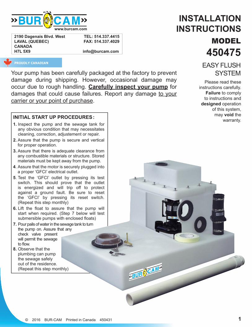
Your pump has been carefully packaged at the factory to prevent damage during shipping. However, occasional damage may occur due to rough handling. Carefully inspect your pump for damages that could cause failures. Report any damage to your carrier or your point of purchase.
MODEL450475
EASY FLUSH SYSTEM
2190 Dagenais Blvd. West TEL: 514.337.4415 LAVAL (QUEBEC) FAX: 514.337.4029 CANADA H7L 5X9 [email protected]
INITIAL START UP PROCEDURES :1. Inspect the pump and the sewage tank for
any obvious condition that may necessitates cleaning, correction, adjustement or repair.
2. Assure that the pump is secure and vertical for proper operation.
3. Assure that there is adequate clearance from any combustible materials or structure. Stored materials must be kept away from the pump.
4. Assure that the motor is securely plugged into a proper ‘GFCI’ electrical outlet.
5. Test the ‘GFCI’ outlet by pressing its test switch. This should prove that the outlet is energized and will trip off to protect against a ground fault. Be sure to reset the ‘GFCI’ by pressing its reset switch. (Repeat this step monthly)
6. Lift the float to assure that the pump will start when required. (Step 7 below will test submersible pumps with enclosed floats)
7. Pour pails of water in the sewage tank to turn the pump on. Assure that any check valve present will permit the sewage to flow.
8. Observe that the plumbing can pump the sewage safely out of the residence. (Repeat this step monthly)
© 2016 BUR-CAM Printed in Canada 450431
SAFETY INSTRUCTIONS :This fine pump that you just have purchased is designed from the latest in material and workmanship. Before installation and operation, we recommend the following procedures :
Check with your local electrical and plumbing codes to ensure you comply with the regulations. These codes have been designed with your safety in mind. Be sure you comply with them.
We recommend that a separate circuit be lead from the home electrical distribution panel properly protected with a fuse or a circuit breaker. We also recommend that a ground fault circuit be used. Consult a licensed electrician for all wiring.
The ground terminal on the three prong plugs should never be removed. They are supplied and designed for your protection.
Never make adjustments to any electrical appliance or product with the power connected. Do not only unscrew the fuse or trip the breaker, remove the power plug from the receptacle.
ELECTRICAL CONNECTION :For pumping systems using more than one pump, each pump needs to be connected to a separate dedicated circuit protected by a fuse or breaker. This way, the power supply of one pump will not stop operating if the fuse of one of the pumps burns or if the breaker of one of the pumps trips.
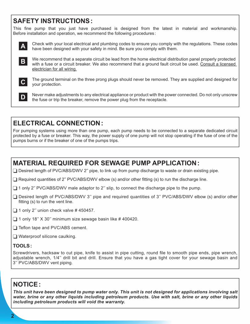
NOTICE :This unit have been designed to pump water only. This unit is not designed for applications involving salt water, brine or any other liquids including petroleum products. Use with salt, brine or any other liquids including petroleum products will void the warranty.
MATERIAL REQUIRED FOR SEWAGE PUMP APPLICATION : Desired length of PVC/ABS/DWV 2’’ pipe, to link up from pump discharge to waste or drain existing pipe.
Required quantities of 2’’ PVC/ABS/DWV elbow (s) and/or other fitting (s) to run the discharge line.
1 only 2’’ PVC/ABS/DWV male adaptor to 2’’ slip, to connect the discharge pipe to the pump.
Desired length of PVC/ABS/DWV 3’’ pipe and required quantities of 3’’ PVC/ABS/DWV elbow (s) and/or other fitting (s) to run the vent line.
1 only 2’’ union check valve # 450457.
1 only 18’’ X 30’’ minimum size sewage basin like # 400420.
Teflon tape and PVC/ABS cement.
Waterproof silicone caulking.
TOOLS :Screwdrivers, hacksaw to cut pipe, knife to assist in pipe cutting, round file to smooth pipe ends, pipe wrench, adjustable wrench, 1/4’’ drill bit and drill. Ensure that you have a gas tight cover for your sewage basin and 3’’ PVC/ABS/DWV vent piping.
A
B
C
D
2
3
APPLICATIONS :• This domestic submersible sewage system is
designed and suitable for raw sewage applications where the total head requirements do not exceed 15 feet, including pipe friction losses. For higher lifts, consult factory.
• CAPACITY 5’ 4500 US GPH 10’ 3120 US GPH 15’ 720 US GPH Friction loss in pipe not included
FEATURES :• Vortex designed impeller made from glass filled
Noryl, will not corrode.• Rugged cast iron pump body.• Stainless steel mechanical rotary type motor seal.• 2’’ NPT pump discharge.• Thermal and overload protection.• Vertical type switch, 15A.• 1/2 HP, 115 V AC, 60 Hz, 9.2 A (18 A at start).
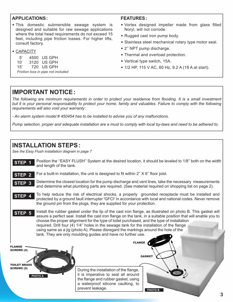
INSTALLATION STEPS :See the Easy Flush installation diagram in page 7
Position the ‘‘EASY FLUSH’’ System at the desired location, it should be leveled to 1/8’’ both on the width and length of the tank.
For a built-in installation, the unit is designed to fit within 2’’ X 6’’ floor joist.
Determine the closest location for the pump discharge and vent lines, take the necessary measurements and determine what plumbing parts are required. (See material required on shopping list on page 2).
To help reduce the risk of electrical shocks, a properly grounded receptacle must be installed and protected by a ground fault interrupter 'GFCI' in accordance with local and national codes. Never remove the ground pin from the plugs, they are supplied for your protection.
Install the rubber gasket under the lip of the cast iron flange, as illustrated on photo B. This gasket will assure a perfect seal. Install the cast iron flange on the tank, in a suitable position that will enable you to choose the proper alignment for the type of toilet purchased, and the type of installation required. Drill four (4) 1/4’’ holes in the sewage tank for the installation of the flange using same as a jig (photo A). Please disregard the markings around the hole of the tank. They are only moulding guides and have no further use.
IMPORTANT NOTICE :The following are minimum requirements in order to protect your residence from flooding. It is a small investment but it is your personal responsability to protect your home, family and valuables. Failure to comply with the following requirements will also void your warranty :
- An alarm system model # 450454 has to be installed to advise you of any malfunctions.
Pump selection, proper and adequate installation are a must to comply with local by-laws and need to be adhered to.
PHOTO A
PHOTO B
TOILET BRASS SCREWS (2)
FLANGE SCREWS (4)
FLANGE
GASKET
During the installation of the flange, it is imperative to seal all around the flange and rubber gasket, using a waterproof silicone caulking, to prevent leakage.
STEP 1
STEP 2
STEP 3
STEP 4
STEP 5
4
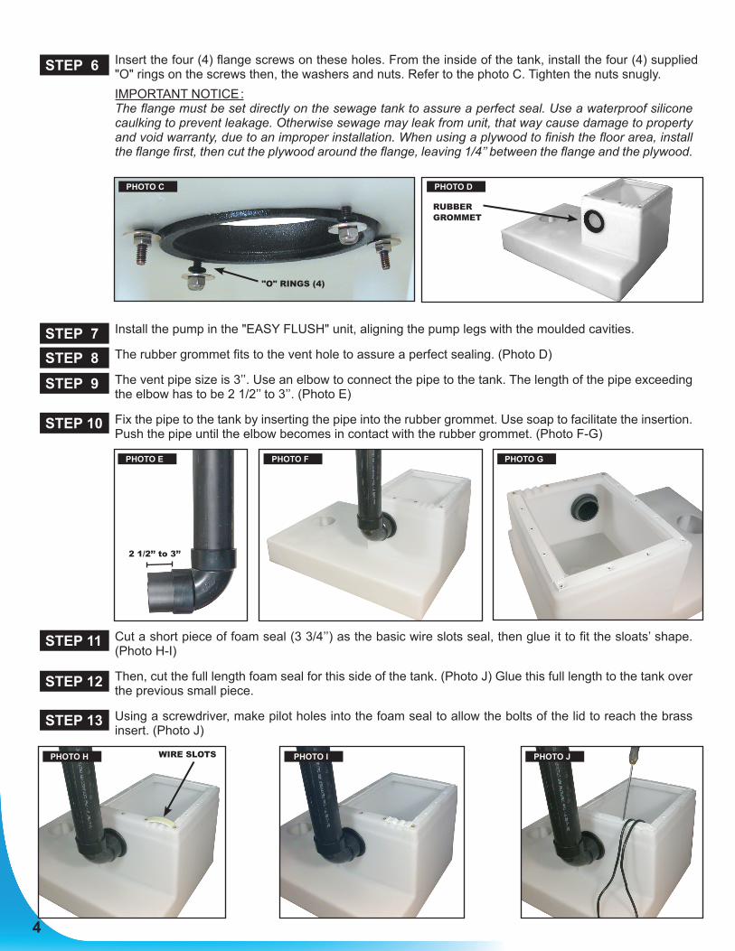
Insert the four (4) flange screws on these holes. From the inside of the tank, install the four (4) supplied "O" rings on the screws then, the washers and nuts. Refer to the photo C. Tighten the nuts snugly.
IMPORTANT NOTICE : The flange must be set directly on the sewage tank to assure a perfect seal. Use a waterproof silicone
caulking to prevent leakage. Otherwise sewage may leak from unit, that way cause damage to property and void warranty, due to an improper installation. When using a plywood to finish the floor area, install the flange first, then cut the plywood around the flange, leaving 1/4’’ between the flange and the plywood.
Install the pump in the "EASY FLUSH" unit, aligning the pump legs with the moulded cavities.
The rubber grommet fits to the vent hole to assure a perfect sealing. (Photo D)
The vent pipe size is 3’’. Use an elbow to connect the pipe to the tank. The length of the pipe exceeding the elbow has to be 2 1/2’’ to 3’’. (Photo E)
Fix the pipe to the tank by inserting the pipe into the rubber grommet. Use soap to facilitate the insertion. Push the pipe until the elbow becomes in contact with the rubber grommet. (Photo F-G)
Cut a short piece of foam seal (3 3/4’’) as the basic wire slots seal, then glue it to fit the sloats’ shape. (Photo H-I)
Then, cut the full length foam seal for this side of the tank. (Photo J) Glue this full length to the tank over the previous small piece.
Using a screwdriver, make pilot holes into the foam seal to allow the bolts of the lid to reach the brass insert. (Photo J)
STEP 6
STEP 7STEP 8
STEP 10
STEP 9
STEP 11
STEP 12
STEP 13
"O" RINGS (4)
RUBBER GROMMET
PHOTO C PHOTO D
PHOTO E
2 1/2’’ to 3’’
PHOTO G
PHOTO JPHOTO IPHOTO H
PHOTO F
WIRE SLOTS
5
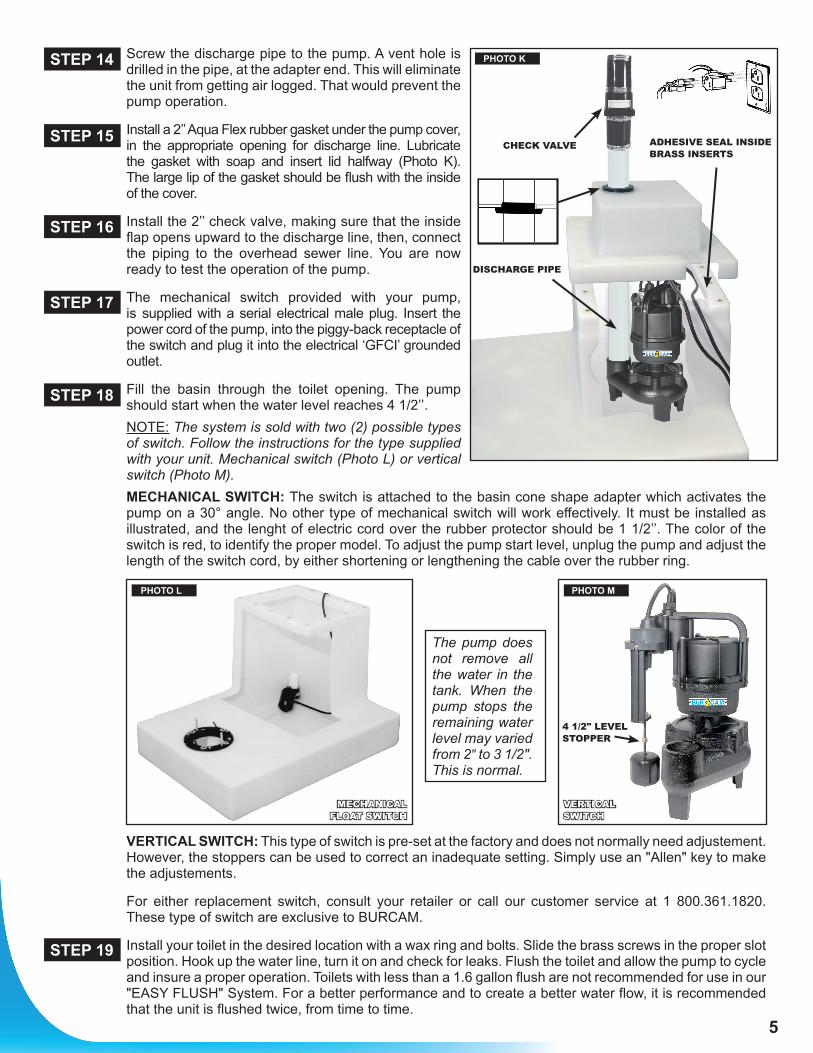
Screw the discharge pipe to the pump. A vent hole is drilled in the pipe, at the adapter end. This will eliminate the unit from getting air logged. That would prevent the pump operation.
Install a 2’’ Aqua Flex rubber gasket under the pump cover, in the appropriate opening for discharge line. Lubricate the gasket with soap and insert lid halfway (Photo K). The large lip of the gasket should be flush with the inside of the cover.
Install the 2’’ check valve, making sure that the inside flap opens upward to the discharge line, then, connect the piping to the overhead sewer line. You are now ready to test the operation of the pump.
The mechanical switch provided with your pump, is supplied with a serial electrical male plug. Insert the power cord of the pump, into the piggy-back receptacle of the switch and plug it into the electrical ‘GFCI’ grounded outlet.
Fill the basin through the toilet opening. The pump should start when the water level reaches 4 1/2’’.
NOTE: The system is sold with two (2) possible types of switch. Follow the instructions for the type supplied with your unit. Mechanical switch (Photo L) or vertical switch (Photo M).
MECHANICAL SWITCH: The switch is attached to the basin cone shape adapter which activates the pump on a 30° angle. No other type of mechanical switch will work effectively. It must be installed as illustrated, and the lenght of electric cord over the rubber protector should be 1 1/2’’. The color of the switch is red, to identify the proper model. To adjust the pump start level, unplug the pump and adjust the length of the switch cord, by either shortening or lengthening the cable over the rubber ring.
VERTICAL SWITCH: This type of switch is pre-set at the factory and does not normally need adjustement. However, the stoppers can be used to correct an inadequate setting. Simply use an "Allen" key to make the adjustements.
For either replacement switch, consult your retailer or call our customer service at 1 800.361.1820. These type of switch are exclusive to BURCAM.
Install your toilet in the desired location with a wax ring and bolts. Slide the brass screws in the proper slot position. Hook up the water line, turn it on and check for leaks. Flush the toilet and allow the pump to cycle and insure a proper operation. Toilets with less than a 1.6 gallon flush are not recommended for use in our "EASY FLUSH" System. For a better performance and to create a better water flow, it is recommended that the unit is flushed twice, from time to time.
STEP 14
STEP 15
STEP 16
STEP 17
STEP 18
STEP 19
PHOTO MPHOTO L
VERTICAL SWITCH
4 1/2" LEVEL STOPPER
MECHANICAL FLOAT SWITCH
CHECK VALVE
DISCHARGE PIPE
ADHESIVE SEAL INSIDE BRASS INSERTS
PHOTO K
The pump does not remove all the water in the tank. When the pump stops the remaining water level may varied from 2" to 3 1/2". This is normal.
6
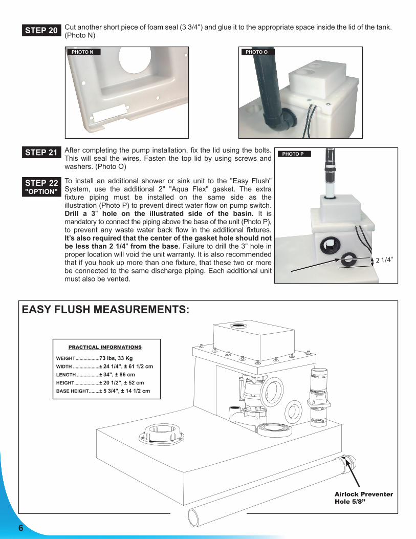
Cut another short piece of foam seal (3 3/4") and glue it to the appropriate space inside the lid of the tank. (Photo N)
After completing the pump installation, fix the lid using the bolts. This will seal the wires. Fasten the top lid by using screws and washers. (Photo O)
To install an additional shower or sink unit to the "Easy Flush" System, use the additional 2" "Aqua Flex" gasket. The extra fixture piping must be installed on the same side as the illustration (Photo P) to prevent direct water flow on pump switch. Drill a 3" hole on the illustrated side of the basin. It is mandatory to connect the piping above the base of the unit (Photo P), to prevent any waste water back flow in the additional fixtures. It’s also required that the center of the gasket hole should not be less than 2 1/4" from the base. Failure to drill the 3" hole in proper location will void the unit warranty. It is also recommended that if you hook up more than one fixture, that these two or more be connected to the same discharge piping. Each additional unit must also be vented.
STEP 20
STEP 21
STEP 22 "OPTION"
PHOTO N PHOTO O
EASY FLUSH MEASUREMENTS:
Airlock Preventer Hole 5/8’’
PRACTICAL INFORMATIONS
WEIGHT ..................73 lbs, 33 Kg WIDTH ....................± 24 1/4", ± 61 1/2 cm LENGTH .................± 34", ± 86 cm HEIGHT ...................± 20 1/2", ± 52 cm BASE HEIGHT ........± 5 3/4", ± 14 1/2 cm
PHOTO P
2 1/4"

7
STEP 1Position your "Easy Flush" System as per instructions.
STEP 7Align the pump with the cavities inside the basin.
STEP 2Install the unit between 2" X 6" floor joist.
STEP 3Purchase required plumbing parts.
STEP 16Install the 2" check valve in a vertical position.
STEP 19Install the wax ring and the toilet. Use long brass screws, nuts and washers.
STEP 17Insert the switch in the receptacle, then plug the pump in the piggy-back.
STEP 15Install a 2" "Aqua Flex" rubber gasket under the pump cover.
STEP 12Apply the seal.
STEP 5Install the flange. Do not forget the "O" ring between the tank and the flange.
STEP 13Make pilot holes into the foam seal to allow the bolts of the lid.
"GFCI" Plug type
STEP 4Properly grounded receptacle.
STEP 11Install a short piece of foam seal (3 3/4") as the basic wire slot seal.
STEP 20Install a short piece of foam seal (3 3/4") to the appropriate space inside the lid.
EASY FLUSH APPLICATION :
STEP 14Screw the discharge pipe to the pump base.
STEP 22Additional fixtures can be installed using the additional 2" "Aqua Flex" rubber gasket enclosed.
STEP 21Fix the lid using the bolts.
STEP 18Fill the basin. Check water level. Pump should start at 4 1/2".
STEP 6Align and install the flange. Use the short screws, nuts, "O" rings and washers.
STEP 8-9-10Install the vent line with the 3" "Aqua Flex" rubber gasket enclosed.
2 1/4"
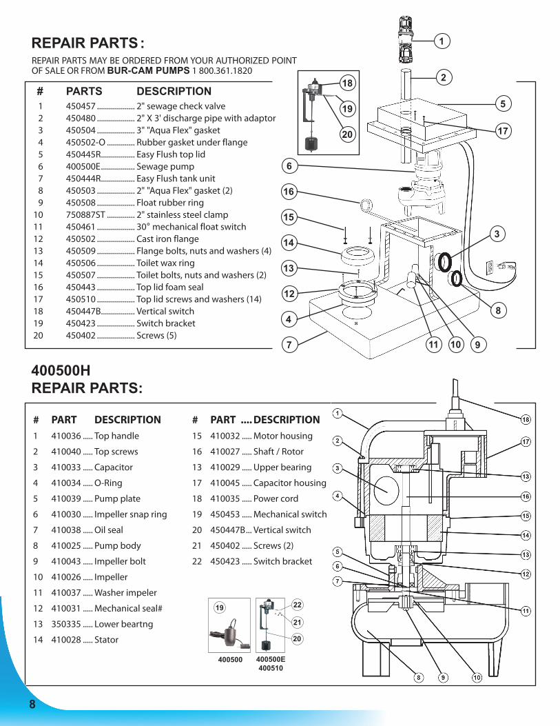
REPAIR PARTS :
400500H REPAIR PARTS:
# PARTS DESCRIPTION 1 450457 ................... 2" sewage check valve 2 450480 ................... 2" X 3' discharge pipe with adaptor 3 450504 ................... 3" "Aqua Flex" gasket 4 450502-O .............. Rubber gasket under flange 5 450445R ................. Easy Flush top lid 6 400500E ................. Sewage pump 7 450444R ................. Easy Flush tank unit 8 450503 ................... 2" "Aqua Flex" gasket (2) 9 450508 ................... Float rubber ring 10 750887ST .............. 2" stainless steel clamp 11 450461 ................... 30° mechanical float switch 12 450502 ................... Cast iron flange 13 450509 ................... Flange bolts, nuts and washers (4) 14 450506 ................... Toilet wax ring 15 450507 ................... Toilet bolts, nuts and washers (2) 16 450443 ................... Top lid foam seal 17 450510 ................... Top lid screws and washers (14) 18 450447B ................. Vertical switch 19 450423 ................... Switch bracket 20 450402 ................... Screws (5)
1
2
3
4
5
17
6
7
8
91011
12
13
14
15
16
18
19
20
REPAIR PARTS MAY BE ORDERED FROM YOUR AUTHORIZED POINT OF SALE OR FROM BUR-CAM PUMPS 1 800.361.1820
# PART DESCRIPTION1 410036 ..... Top handle
2 410040 ..... Top screws
3 410033 ..... Capacitor
4 410034 ..... O-Ring
5 410039 ..... Pump plate
6 410030 ..... Impeller snap ring
7 410038 ..... Oil seal
8 410025 ..... Pump body
9 410043 ..... Impeller bolt
10 410026 ..... Impeller
11 410037 ..... Washer impeler
12 410031 ..... Mechanical seal#
13 350335 ..... Lower beartng
14 410028 ..... Stator
# PART .... DESCRIPTION15 410032 ..... Motor housing
16 410027 ..... Shaft / Rotor
13 410029 ..... Upper bearing
17 410045 ..... Capacitor housing
18 410035 ..... Power cord
19 450453 ..... Mechanical switch
20 450447B ... Vertical switch
21 450402 ..... Screws (2)
22 450423 ..... Switch bracket
400500E400510
400500
21
22
20
19
8
9
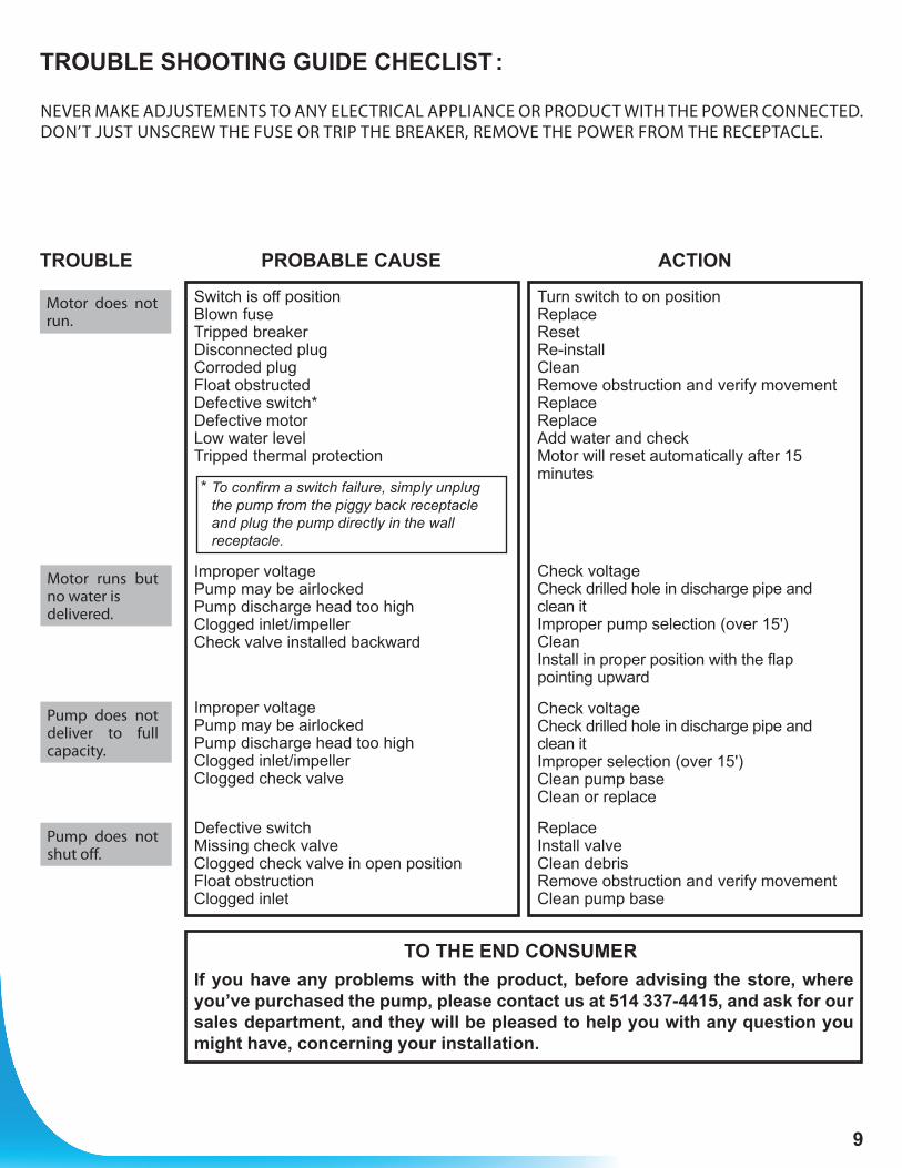
Switch is off position Blown fuse Tripped breaker Disconnected plug Corroded plug Float obstructed Defective switch* Defective motor Low water level Tripped thermal protection
* To confirm a switch failure, simply unplug the pump from the piggy back receptacle and plug the pump directly in the wall receptacle.
Improper voltage Pump may be airlocked Pump discharge head too high Clogged inlet/impeller Check valve installed backward
Improper voltage Pump may be airlocked Pump discharge head too high Clogged inlet/impeller Clogged check valve
Defective switch Missing check valve Clogged check valve in open position Float obstruction Clogged inlet
TO THE END CONSUMERIf you have any problems with the product, before advising the store, where you’ve purchased the pump, please contact us at 514 337-4415, and ask for our sales department, and they will be pleased to help you with any question you might have, concerning your installation.
Turn switch to on position Replace Reset Re-install Clean Remove obstruction and verify movement Replace Replace Add water and check Motor will reset automatically after 15 minutes
Check voltage Check drilled hole in discharge pipe and clean it Improper pump selection (over 15') Clean Install in proper position with the flap pointing upward
Check voltage Check drilled hole in discharge pipe and clean it Improper selection (over 15') Clean pump base Clean or replace
Replace Install valve Clean debris Remove obstruction and verify movement Clean pump base
Motor does not run.
Motor runs but no water is delivered.
Pump does not deliver to full capacity.
Pump does not shut off.
TROUBLE SHOOTING GUIDE CHECLIST :
TROUBLE PROBABLE CAUSE ACTION
NEVER MAKE ADJUSTEMENTS TO ANY ELECTRICAL APPLIANCE OR PRODUCT WITH THE POWER CONNECTED. DON’T JUST UNSCREW THE FUSE OR TRIP THE BREAKER, REMOVE THE POWER FROM THE RECEPTACLE.
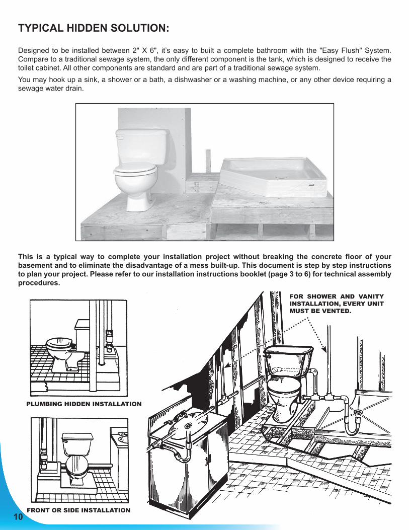
TYPICAL HIDDEN SOLUTION:
Designed to be installed between 2" X 6", it’s easy to built a complete bathroom with the "Easy Flush" System. Compare to a traditional sewage system, the only different component is the tank, which is designed to receive the toilet cabinet. All other components are standard and are part of a traditional sewage system.You may hook up a sink, a shower or a bath, a dishwasher or a washing machine, or any other device requiring a sewage water drain.
This is a typical way to complete your installation project without breaking the concrete floor of your basement and to eliminate the disadvantage of a mess built-up. This document is step by step instructions to plan your project. Please refer to our installation instructions booklet (page 3 to 6) for technical assembly procedures.
10FRONT OR SIDE INSTALLATION
PLUMBING HIDDEN INSTALLATION
FOR SHOWER AND VANITY INSTALLATION, EVERY UNIT MUST BE VENTED.
11
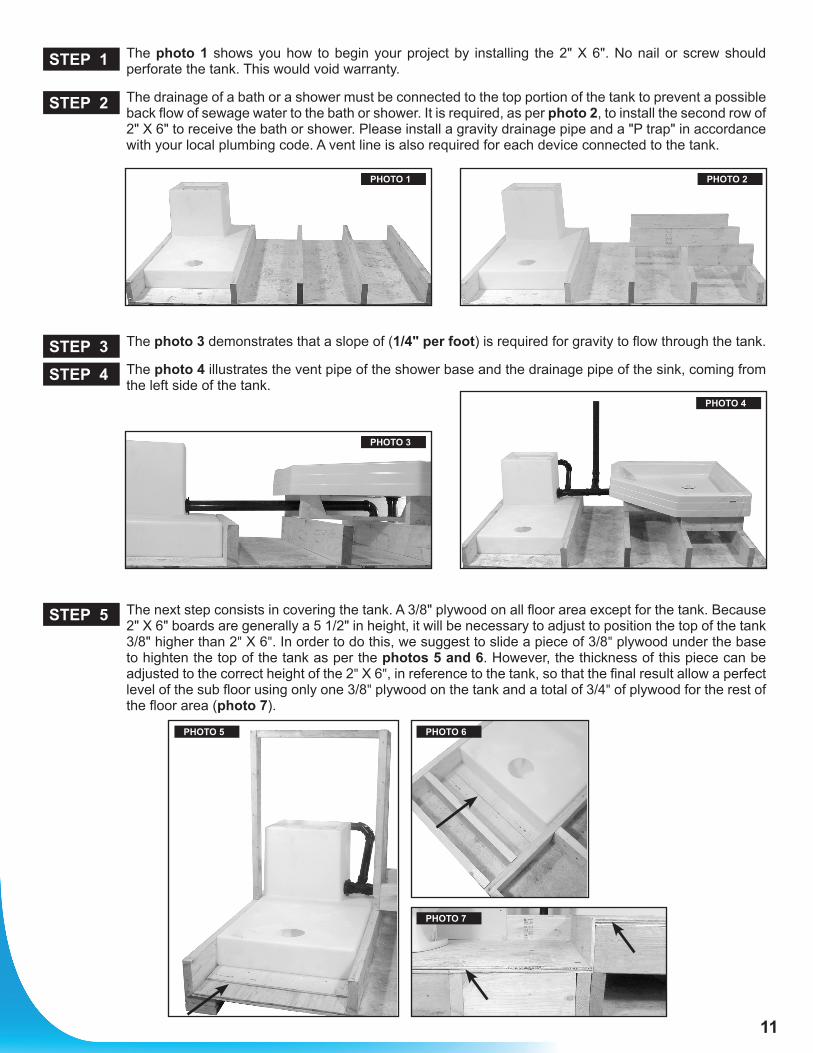
The photo 1 shows you how to begin your project by installing the 2" X 6". No nail or screw should perforate the tank. This would void warranty.
The drainage of a bath or a shower must be connected to the top portion of the tank to prevent a possible back flow of sewage water to the bath or shower. It is required, as per photo 2, to install the second row of 2" X 6" to receive the bath or shower. Please install a gravity drainage pipe and a "P trap" in accordance with your local plumbing code. A vent line is also required for each device connected to the tank.
The photo 3 demonstrates that a slope of (1/4" per foot) is required for gravity to flow through the tank.
The photo 4 illustrates the vent pipe of the shower base and the drainage pipe of the sink, coming from the left side of the tank.
The next step consists in covering the tank. A 3/8" plywood on all floor area except for the tank. Because 2" X 6" boards are generally a 5 1/2" in height, it will be necessary to adjust to position the top of the tank 3/8" higher than 2" X 6". In order to do this, we suggest to slide a piece of 3/8" plywood under the base to highten the top of the tank as per the photos 5 and 6. However, the thickness of this piece can be adjusted to the correct height of the 2" X 6", in reference to the tank, so that the final result allow a perfect level of the sub floor using only one 3/8" plywood on the tank and a total of 3/4" of plywood for the rest of the floor area (photo 7).
STEP 1
STEP 2
STEP 3
STEP 4
STEP 5
PHOTO 1
PHOTO 3
PHOTO 4
PHOTO 6PHOTO 5
PHOTO 7
PHOTO 2
12
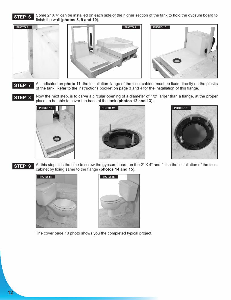
Some 2" X 4" can be installed on each side of the higher section of the tank to hold the gypsum board to finish the wall (photos 8, 9 and 10).
As indicated on photo 11, the installation flange of the toilet cabinet must be fixed directly on the plastic of the tank. Refer to the instructions booklet on page 3 and 4 for the installation of this flange.
Now the next step, is to carve a circular opening of a diameter of 1/2" larger than a flange, at the proper place, to be able to cover the base of the tank (photos 12 and 13).
At this step, it is the time to screw the gypsum board on the 2" X 4" and finish the installation of the toilet cabinet by fixing same to the flange (photos 14 and 15).
The cover page 10 photo shows you the completed typical project.
STEP 6
STEP 7
STEP 8
STEP 9
PHOTO 8
PHOTO 12
PHOTO 14
PHOTO 13
PHOTO 15
PHOTO 11
PHOTO 9 PHOTO 10