Embed Size (px)
Citation preview
Injection and extraction
• Kickers and septa
• Injection methods– Single-turn hadron injection– Injection errors, filamentation and blow-up– Multi-turn hadron injection– Charge-exchange H- injection– Lepton injection
• Extraction methods– Single-turn (fast) extraction– Non-resonant multi-turn extraction– Resonant multi-turn (slow) extraction
Brennan Goddard (presented by Malika Meddahi)
CERN
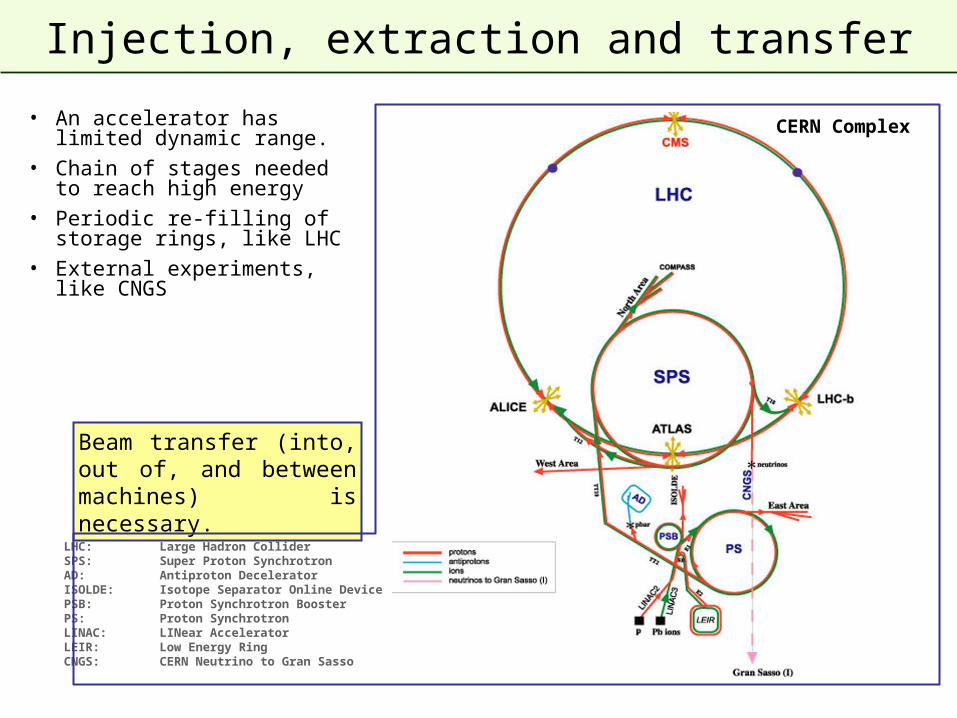
Injection, extraction and transfer
CERN Complex
LHC: Large Hadron ColliderSPS: Super Proton SynchrotronAD: Antiproton DeceleratorISOLDE: Isotope Separator Online DevicePSB: Proton Synchrotron BoosterPS: Proton SynchrotronLINAC: LINear AcceleratorLEIR: Low Energy RingCNGS: CERN Neutrino to Gran Sasso
Beam transfer (into, out of, and between machines) is necessary.
• An accelerator has limited dynamic range.
• Chain of stages needed to reach high energy
• Periodic re-filling of storage rings, like LHC
• External experiments, like CNGS
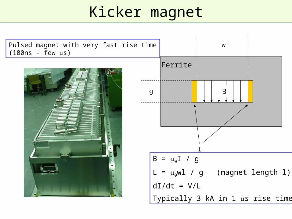
Kicker magnet
I
Ferrite
Bg
B = 0I / g
L = 0wl / g (magnet length l)
dI/dt = V/L
Typically 3 kA in 1 s rise time
wPulsed magnet with very fast rise time(100ns – few s)
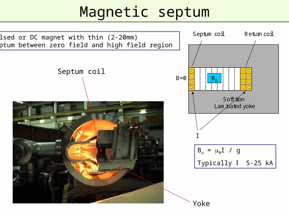
Magnetic septum
Soft iron Laminated yoke
Return coilSeptum coil
B0B=0
Yoke
Septum coil
I
Bo = 0I / g
Typically 5-25 kA
Pulsed or DC magnet with thin (2-20mm)septum between zero field and high field region
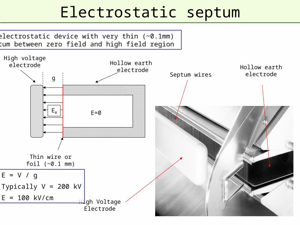
Electrostatic septum
E0 E=0
High voltageelectrode Hollow earth
electrode
Thin wire orfoil (~0.1 mm)
High VoltageElectrode
Hollow earthelectrodeSeptum wires
E = V / g
Typically V = 200 kV
E = 100 kV/cm
g
DC electrostatic device with very thin (~0.1mm)septum between zero field and high field region
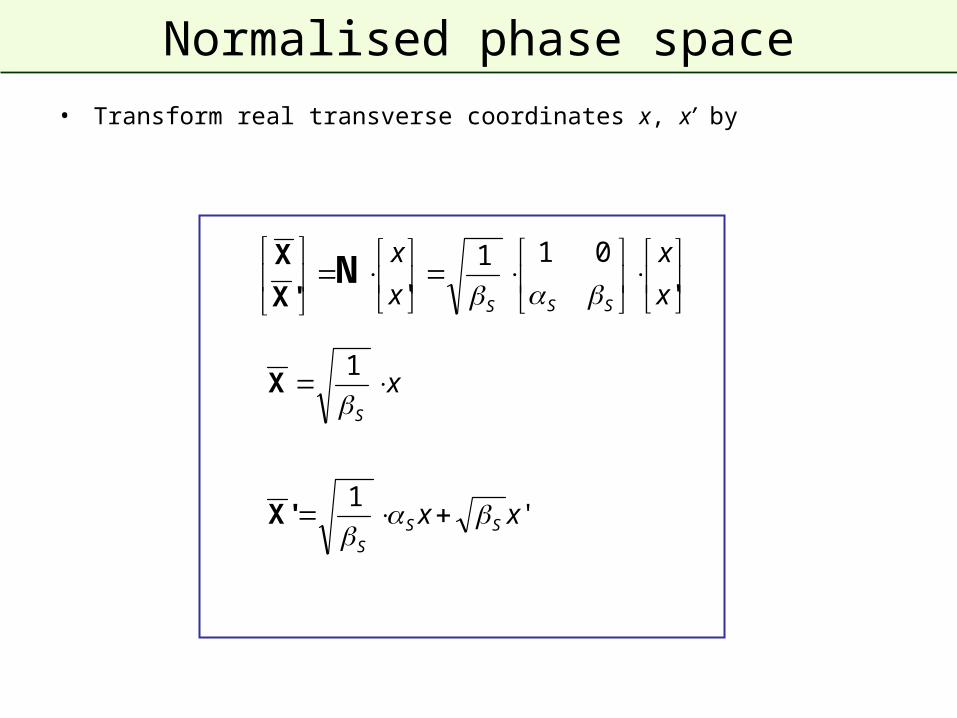
Normalised phase space
• Transform real transverse coordinates x, x’ by
'1
1
xx
x
SSS
S
'X
X
'
011
' x
x
x
x
SSS N
'X
X
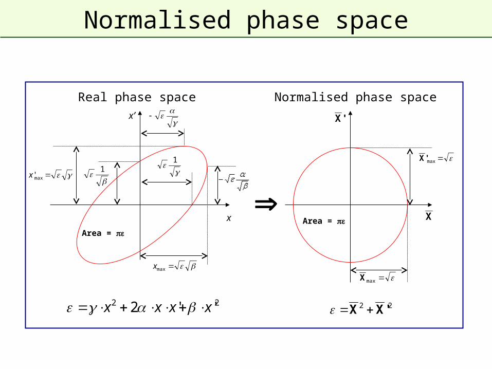
Normalised phase space
1
x
x’
1
max'x
maxx
Area =
maxX
max'X
Area =
22 ''2 xxxx 22 'XX
Real phase space Normalised phase space
X
'X
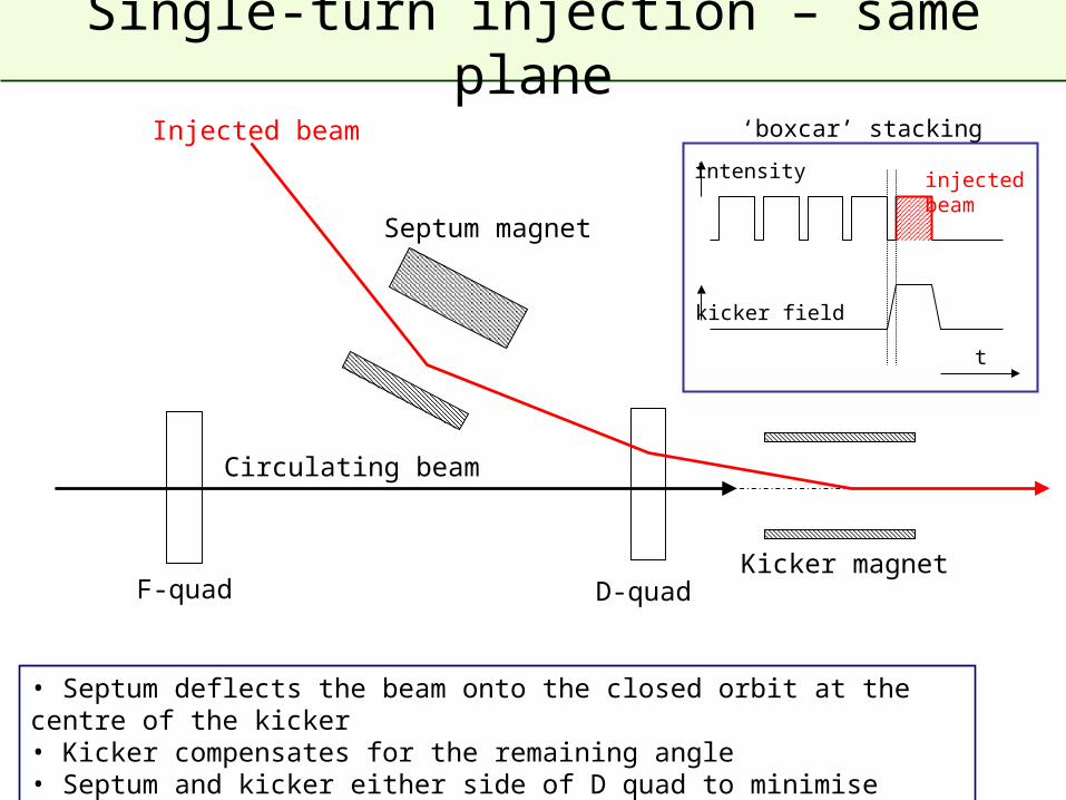
Single-turn injection – same plane
Septum magnet
Kicker magnet
• Septum deflects the beam onto the closed orbit at the centre of the kicker• Kicker compensates for the remaining angle • Septum and kicker either side of D quad to minimise kicker strength
F-quad
t
kicker field
intensity injected beam
‘boxcar’ stackingInjected beam
Circulating beam
D-quad
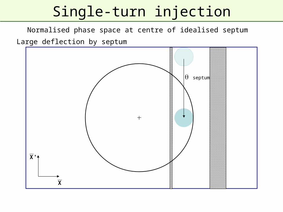
Single-turn injection
Large deflection by septum
septum
Normalised phase space at centre of idealised septum
X
'X
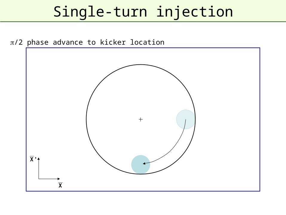
Single-turn injection
/2 phase advance to kicker location
X
'X
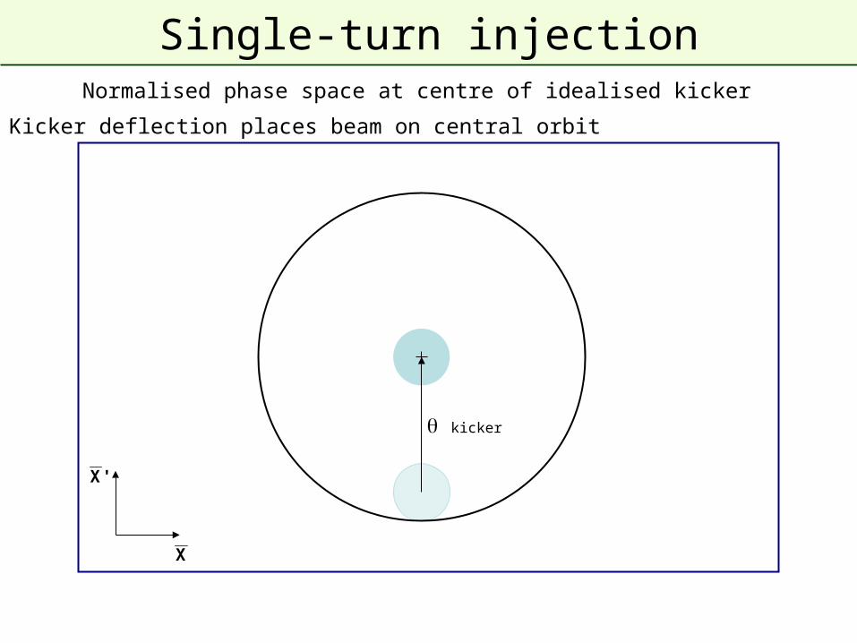
Single-turn injection
Kicker deflection places beam on central orbit
kicker
X
'X
Normalised phase space at centre of idealised kicker
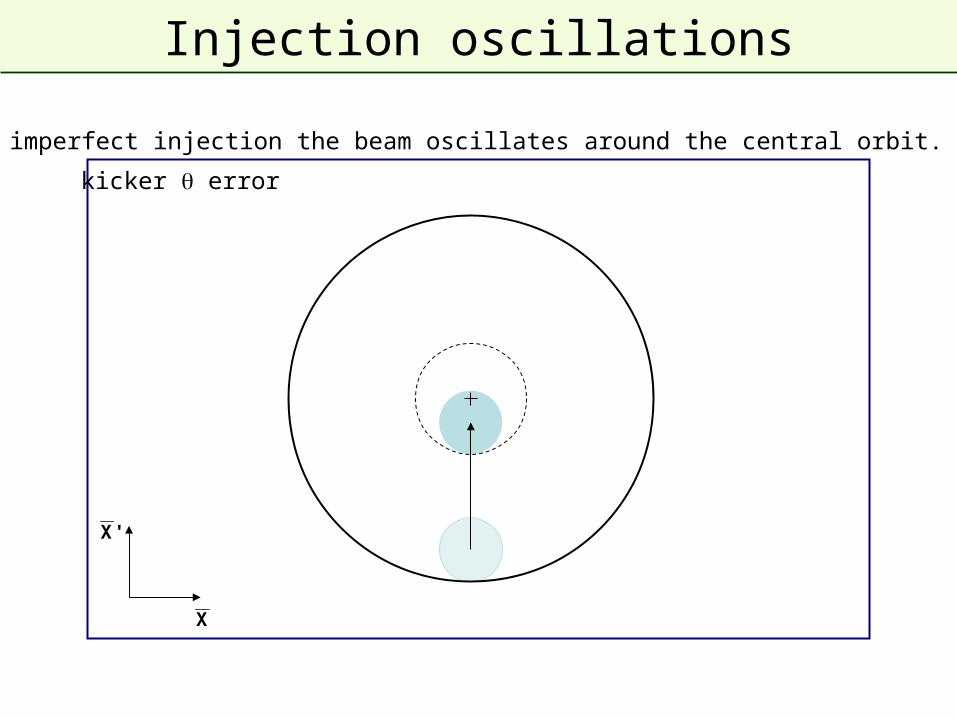
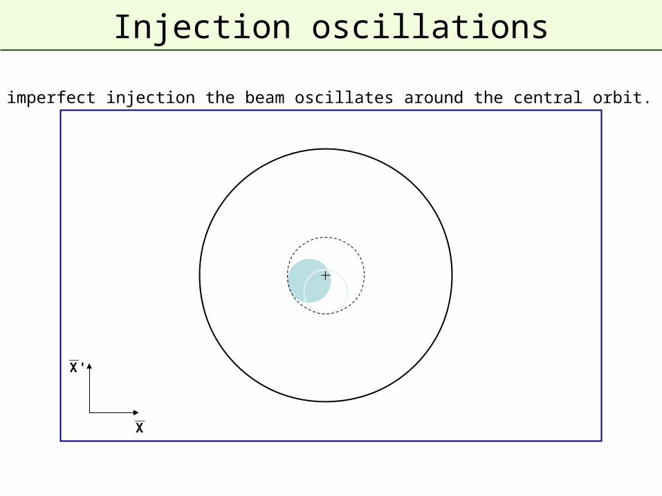
Injection oscillations
For imperfect injection the beam oscillates around the central orbit. 1
kicker error
X
'X
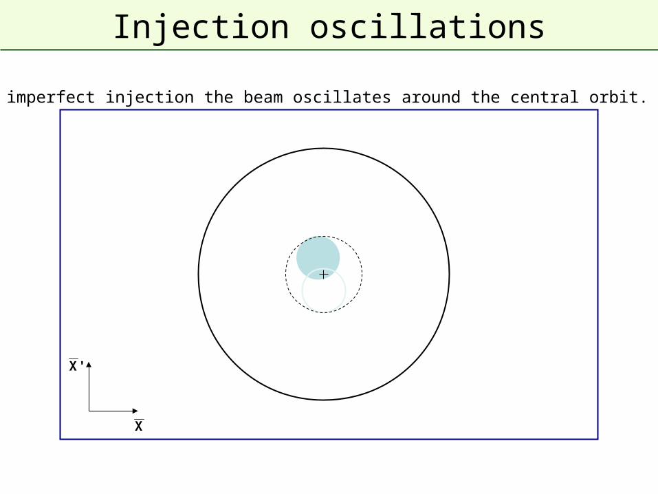
Injection oscillations
For imperfect injection the beam oscillates around the central orbit. 2
X
'X
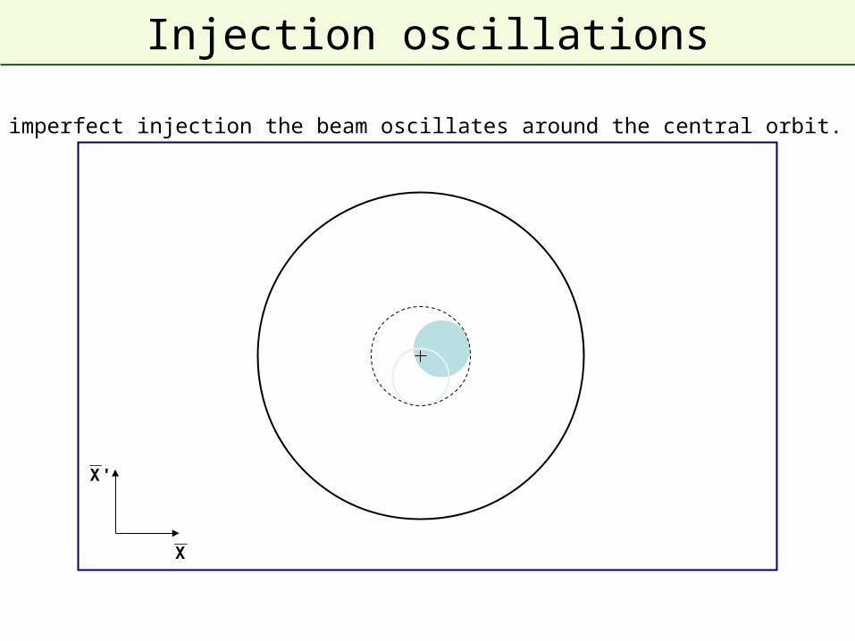
Injection oscillations
For imperfect injection the beam oscillates around the central orbit. 3
X
'X
Injection oscillations
For imperfect injection the beam oscillates around the central orbit. 4
X
'X
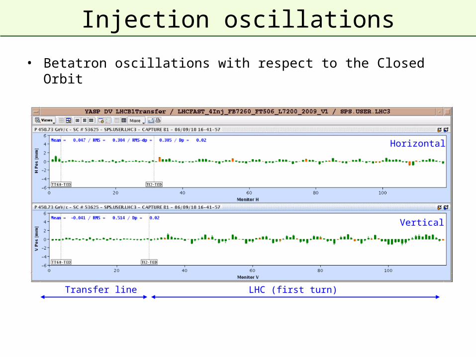
Injection oscillations
• Betatron oscillations with respect to the Closed Orbit
Transfer line LHC (first turn)
Horizontal
Vertical
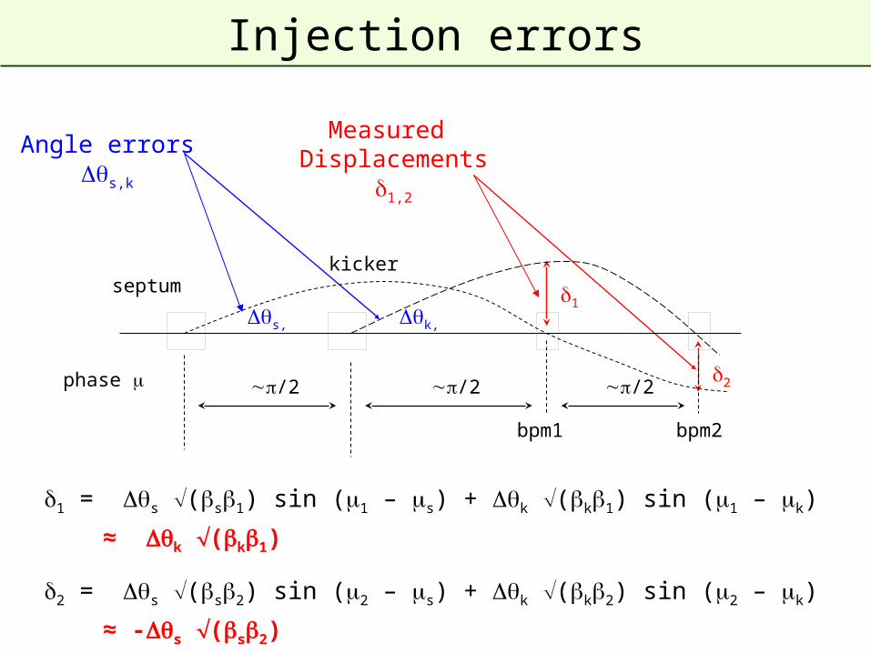
Injection errors
kicker
bpm1 bpm2
phase /2 /2/2
septum
Angle errorss,k
Measured Displacements
1,2
1 = s (s1) sin (1 – s) + k (k1) sin (1 – k)
≈ k (k1)
2 = s (s2) sin (2 – s) + k (k2) sin (2 – k)
≈ -s (s2)
s, k,
1
2
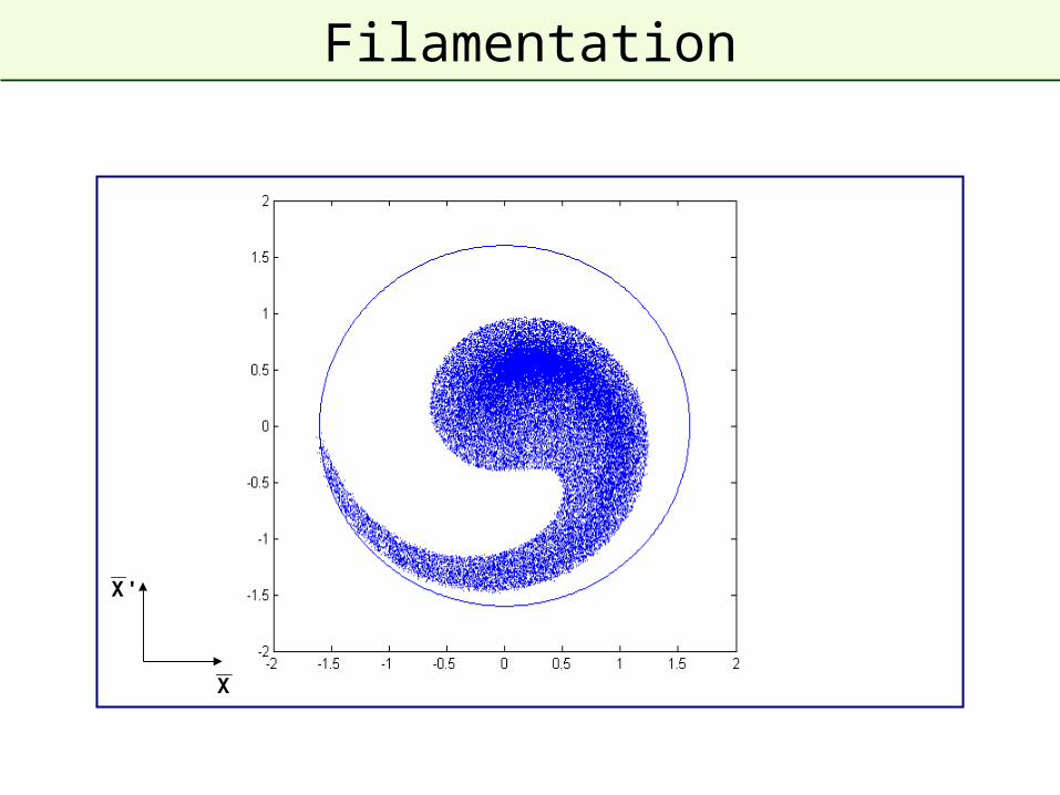
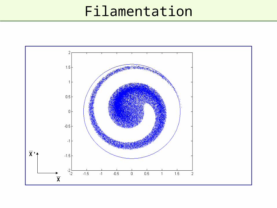
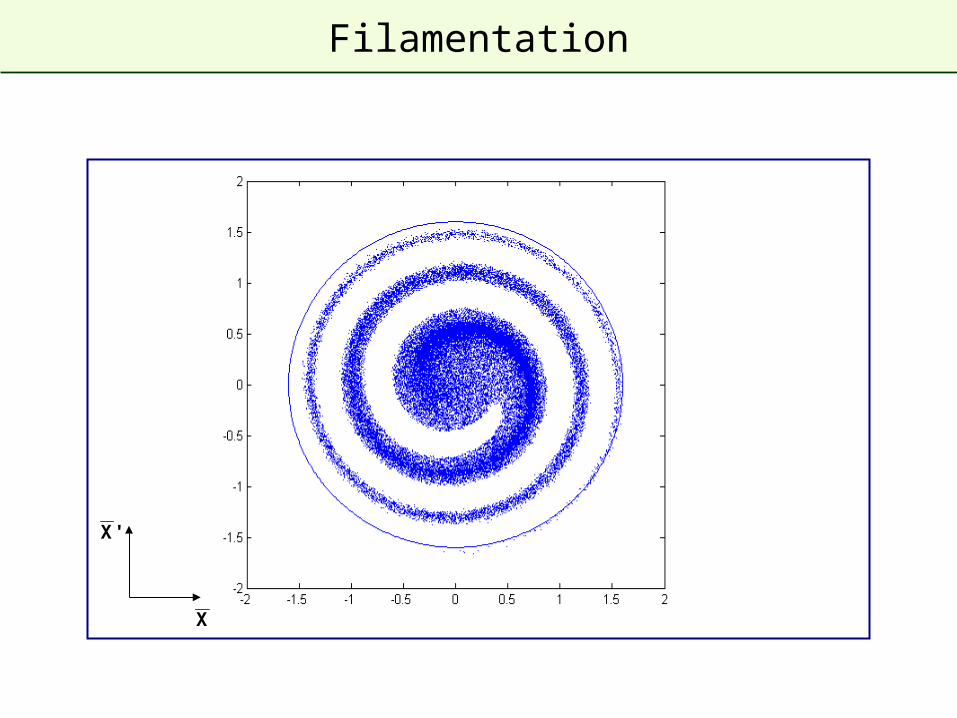
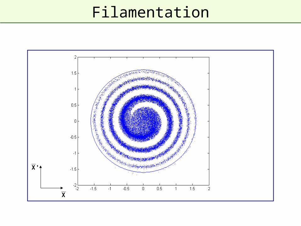
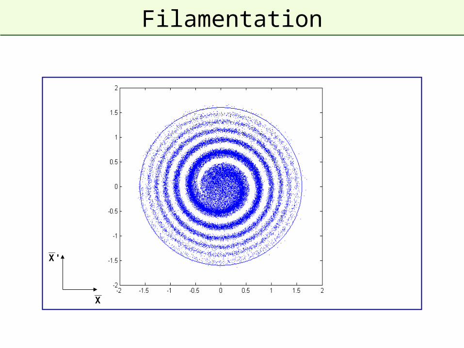
Filamentation
• Non-linear effects (e.g. magnetic field multipoles ) present which introduce amplitude dependent effects into particle motion.
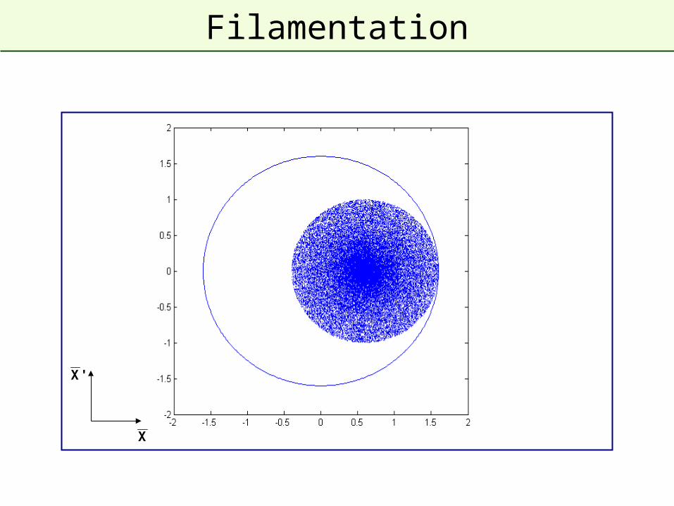
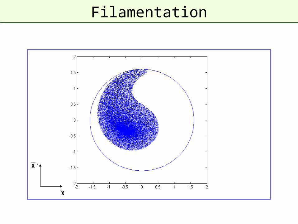
• Over many turns, a phase-space oscillation is transformed into an emittance increase.
• So any residual transverse oscillation will lead to an emittance blow-up through filamentation
– “Transverse damper” systems used to damp injection oscillations - bunch position measured by a pick-up, which is linked to a kicker
X
'X
Filamentation
X
'X
Filamentation
X
'X
Filamentation
X
'X
Filamentation
Filamentation
X
'X
X
'X
Filamentation
X
'X
Filamentation
X
'X
Filamentation
X
'X
Filamentation
X
'X
Filamentation
Damping of injection oscillations
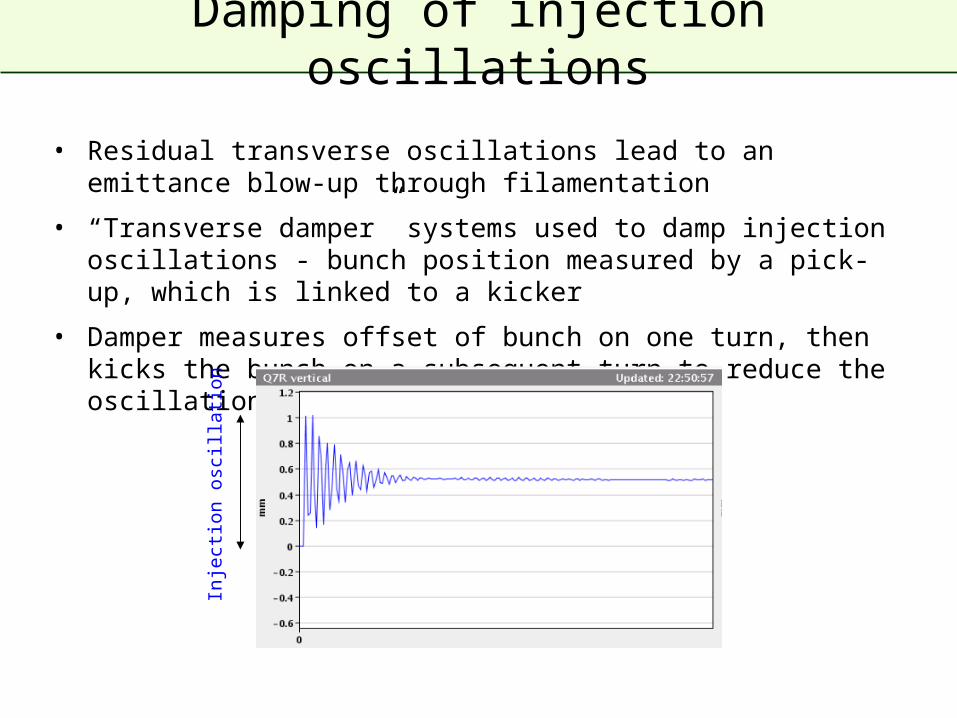
• Residual transverse oscillations lead to an emittance blow-up through filamentation
• “Transverse damper” systems used to damp injection oscillations - bunch position measured by a pick-up, which is linked to a kicker
• Damper measures offset of bunch on one turn, then kicks the bunch on a subsequent turn to reduce the oscillation amplitude
Inje
ctio
n os
cilla
tion
Optical Mismatch at Injection
x
x’
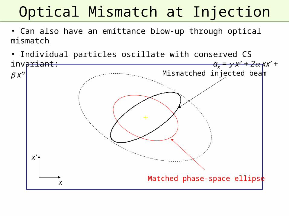
Matched phase-space ellipse
Mismatched injected beam
• Can also have an emittance blow-up through optical mismatch
• Individual particles oscillate with conserved CS invariant: ax = x2 + 2 xx’ + x’2
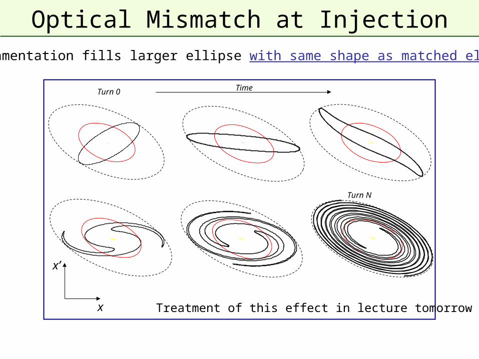
Optical Mismatch at Injection• Filamentation fills larger ellipse with same shape as matched ellipse
x
x’
Treatment of this effect in lecture tomorrow
Turn 0
Turn N
Time
Multi-turn injection
• For hadrons the beam density at injection can be limited either by
space charge effects or by the injector capacity
• If we cannot increase charge density, we can sometimes fill the
horizontal phase space to increase overall injected intensity.
– Condition that the acceptance of receiving machine is larger than the
delivered beam emittance
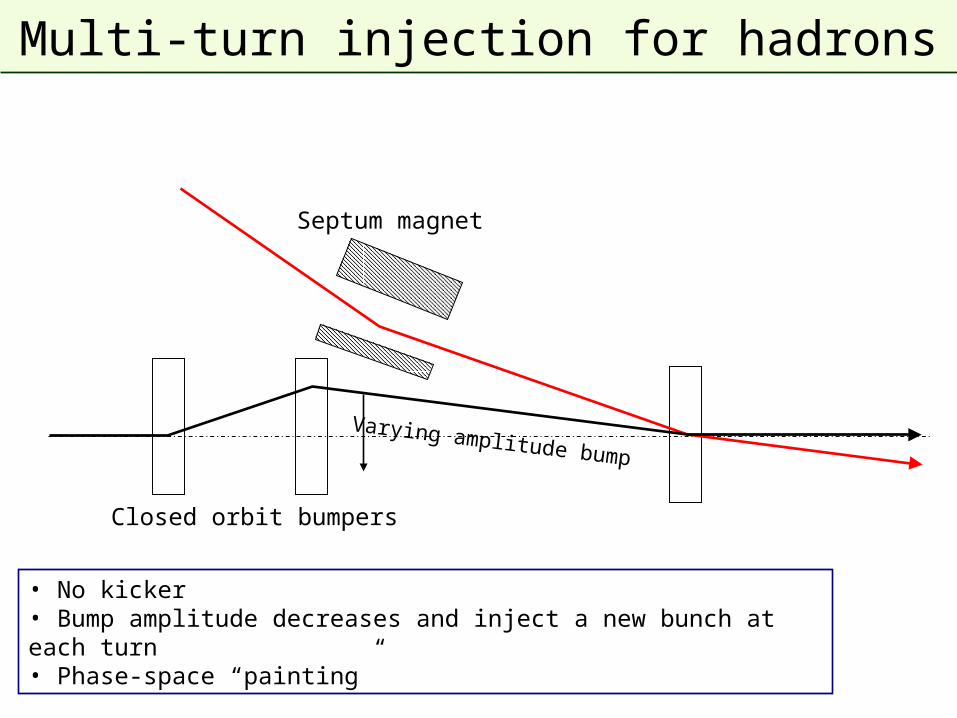
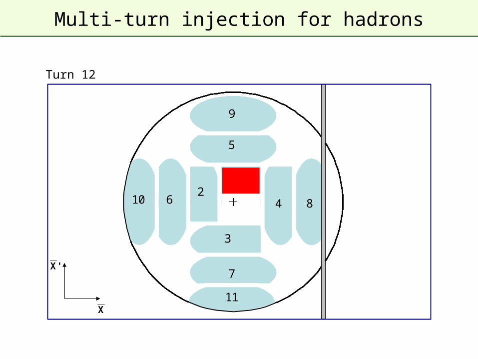
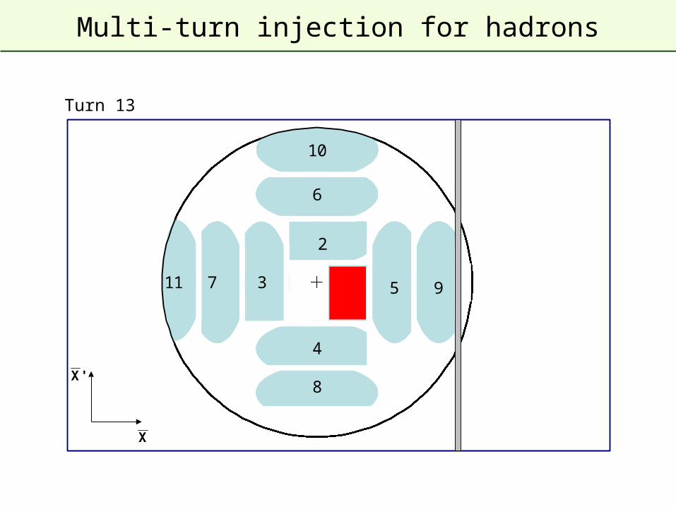
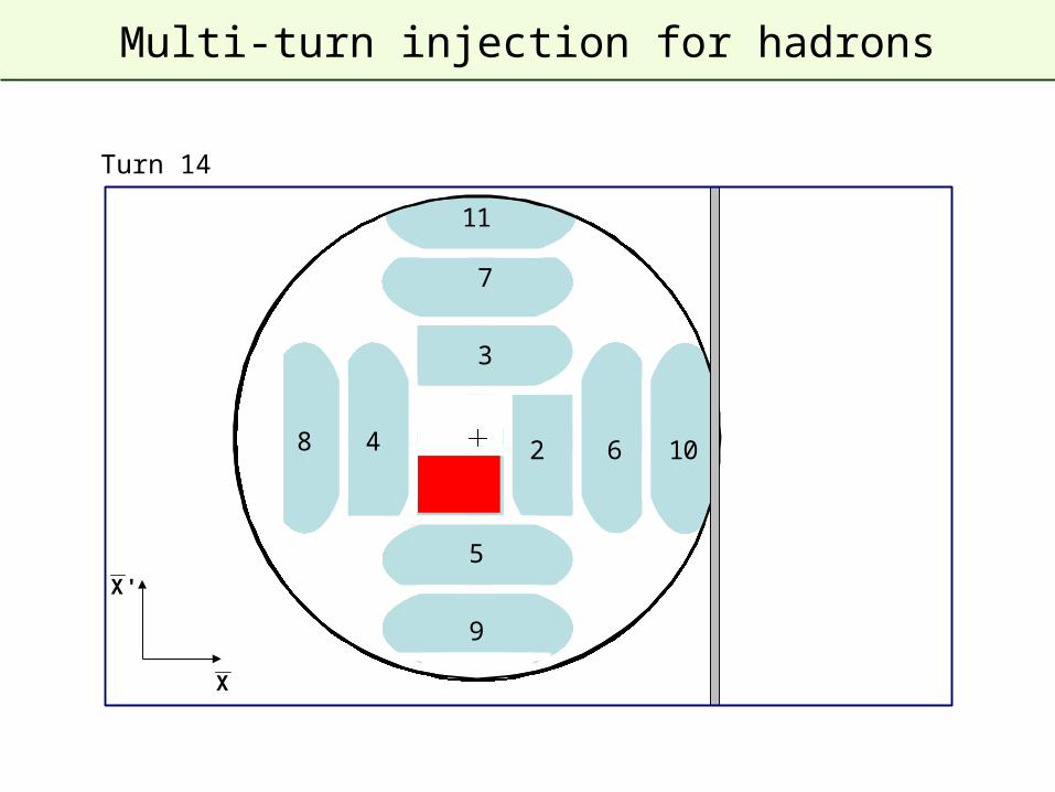
Multi-turn injection for hadrons
Septum magnet
• No kicker • Bump amplitude decreases and inject a new bunch at each turn• Phase-space “painting”
Closed orbit bumpers
Varying amplitude bump
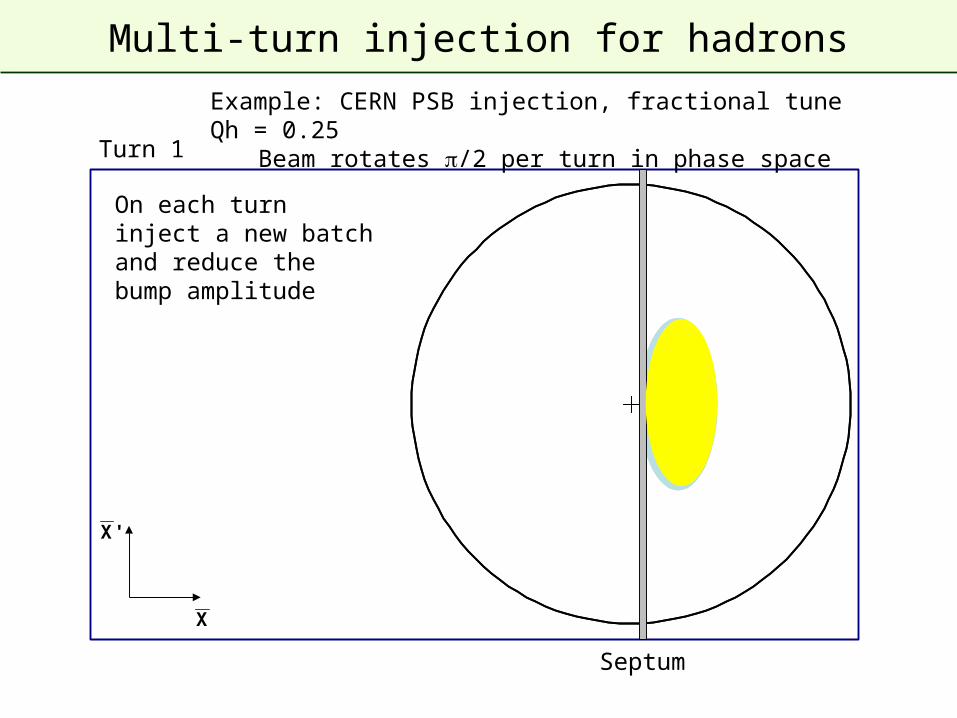
Multi-turn injection for hadrons
1
Turn 1
Septum
X
'X
Example: CERN PSB injection, fractional tune Qh = 0.25Beam rotates /2 per turn in phase space
On each turn inject a new batch and reduce the bump amplitude
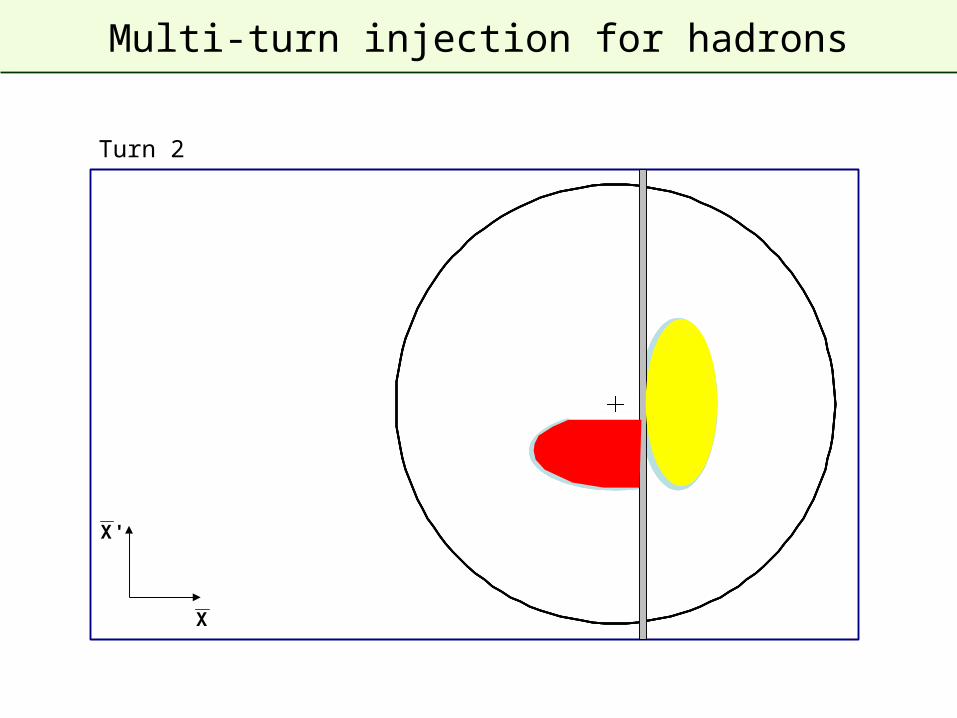
Multi-turn injection for hadrons
1
2
Turn 2
X
'X
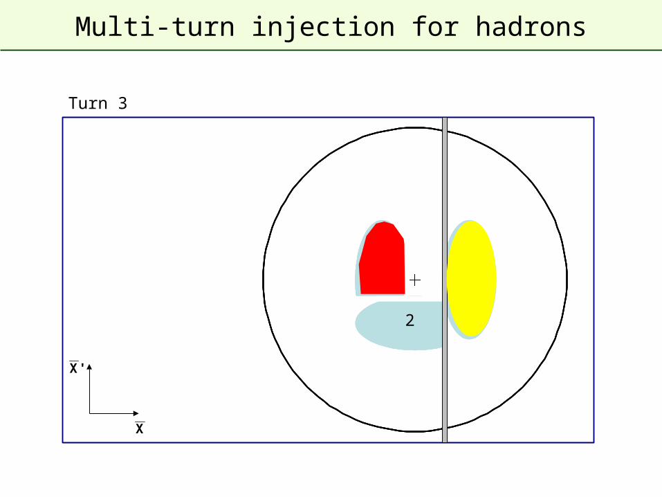
Multi-turn injection for hadrons
3
2
1
Turn 3
X
'X
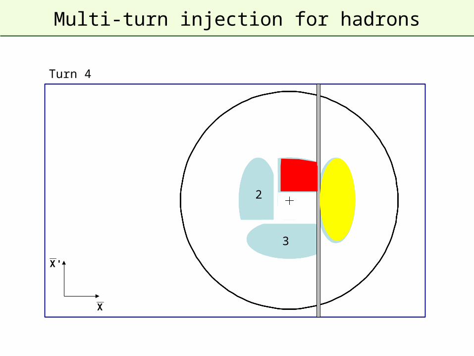
Multi-turn injection for hadrons
4
1
2
3
Turn 4
X
'X
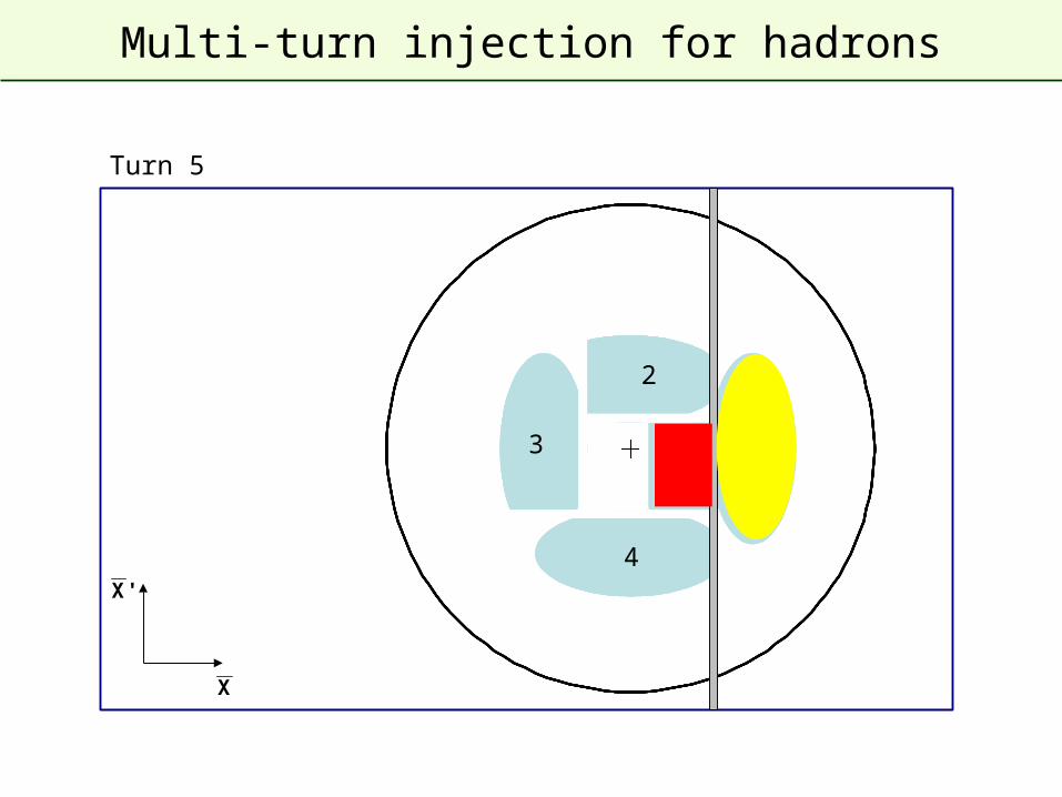
Multi-turn injection for hadrons
3
2
4
51
Turn 5
X
'X
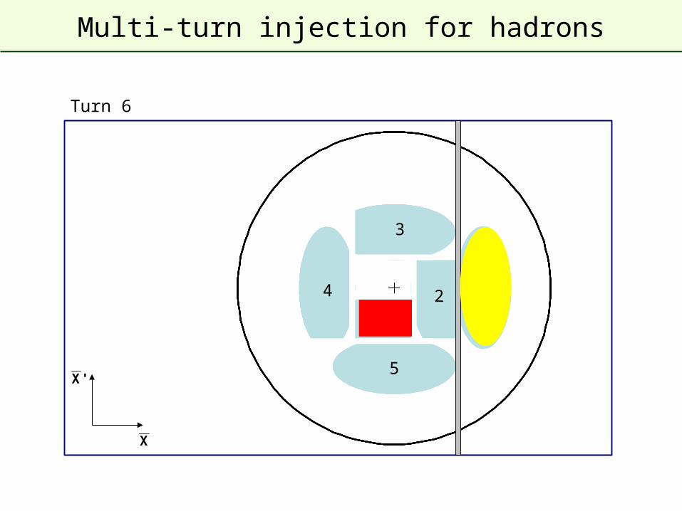
Multi-turn injection for hadrons
6
5
4
3
21
Turn 6
X
'X
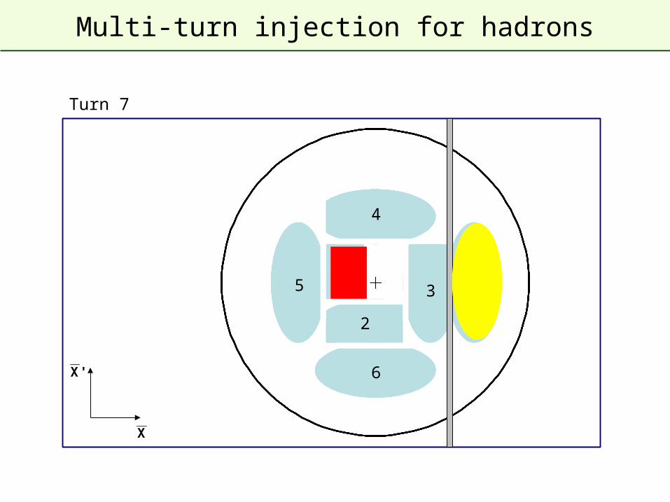
Multi-turn injection for hadrons
7
6
5
4
3
2
1
Turn 7
X
'X
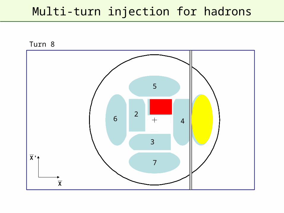
Multi-turn injection for hadrons
7
6
5
4
3
21
8
Turn 8
X
'X
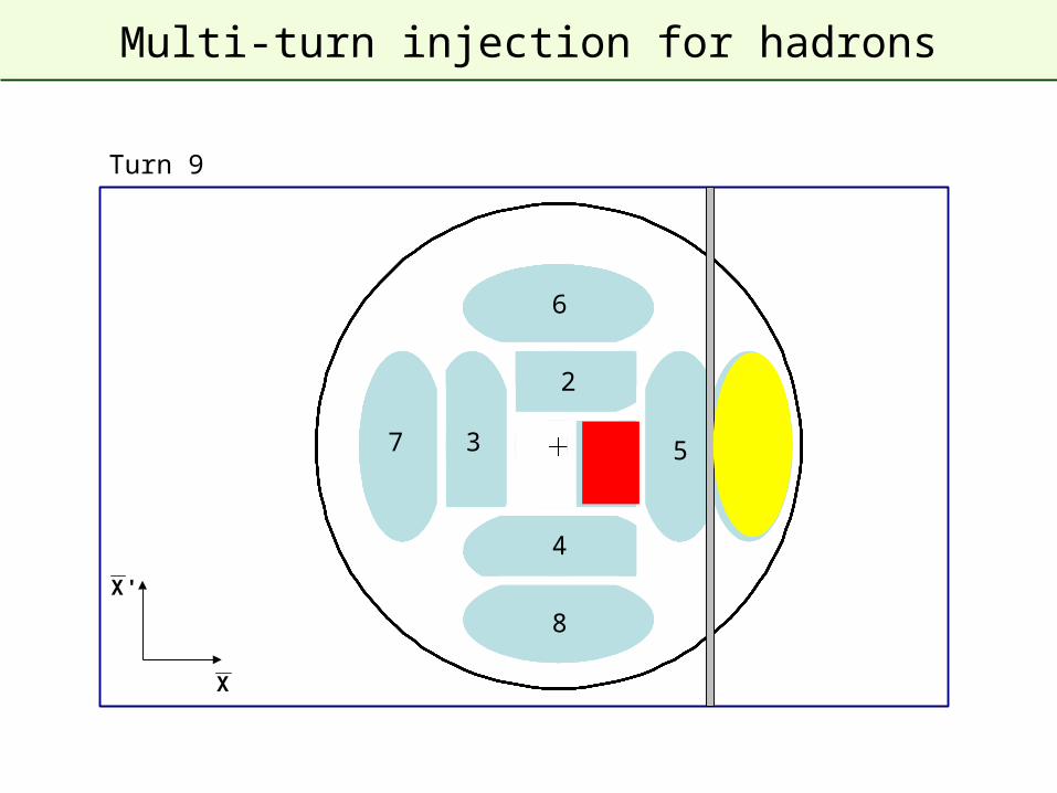
Multi-turn injection for hadrons
7
6
5
4
3
2
1
8
9
Turn 9
X
'X
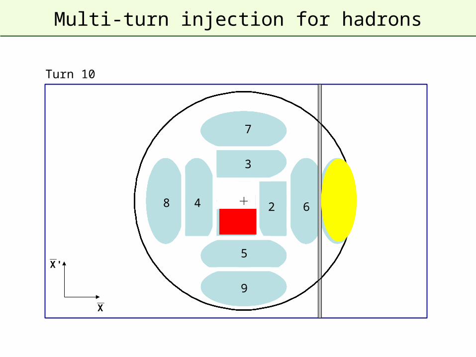
Multi-turn injection for hadrons
7
6
5
4
3
21
8
9
10
Turn 10
X
'X
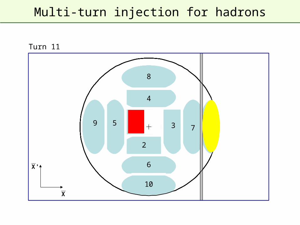
Multi-turn injection for hadrons
7
6
5
4
3
2
1
8
9
10
11
Turn 11
X
'X
Multi-turn injection for hadrons
7
6
5
4
3
21
8
9
10
11
Turn 12
X
'X
Multi-turn injection for hadrons
7
6
5
4
3
2
1
8
9
10
11
Turn 13
X
'X
Multi-turn injection for hadrons
7
6
5
4
3
21
8
9
10
11
Turn 14
X
'X
Multi-turn injection for hadrons
7
6
5
4
3
2
1
8
9
10
11
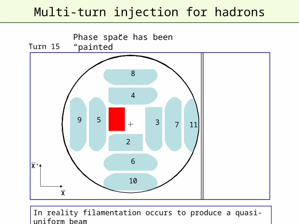
Turn 15
In reality filamentation occurs to produce a quasi-uniform beam
X
'X
Phase space has been “painted”
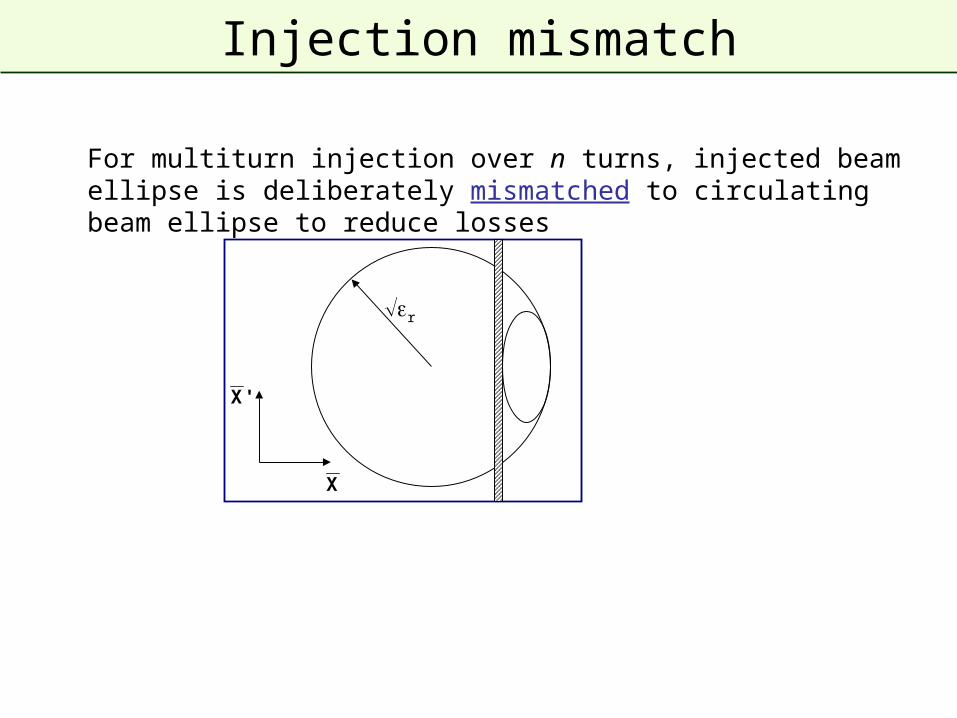
Injection mismatch
For multiturn injection over n turns, injected beam ellipse is deliberately mismatched to circulating beam ellipse to reduce losses
r
X
'X
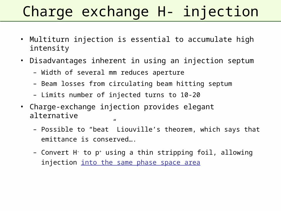
Charge exchange H- injection
• Multiturn injection is essential to accumulate high intensity
• Disadvantages inherent in using an injection septum
– Width of several mm reduces aperture
– Beam losses from circulating beam hitting septum
– Limits number of injected turns to 10-20
• Charge-exchange injection provides elegant alternative
– Possible to “beat” Liouville’s theorem, which says that emittance is
conserved….
– Convert H- to p+ using a thin stripping foil, allowing injection into the
same phase space area
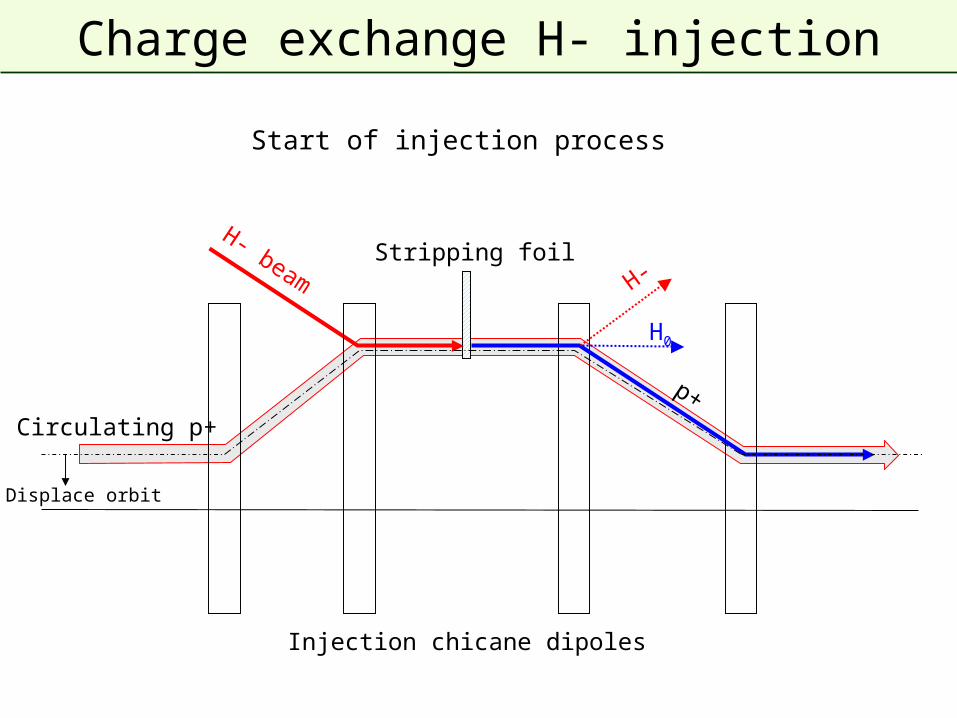
Charge exchange H- injection
H- beam
Injection chicane dipoles
Circulating p+
p+
Stripping foil
H0
H-
Displace orbit
Start of injection process
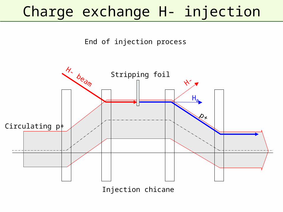
Charge exchange H- injection
H- beam
Injection chicane
Circulating p+
p+
Stripping foil
H0
H-
End of injection process
Charge exchange H- injection
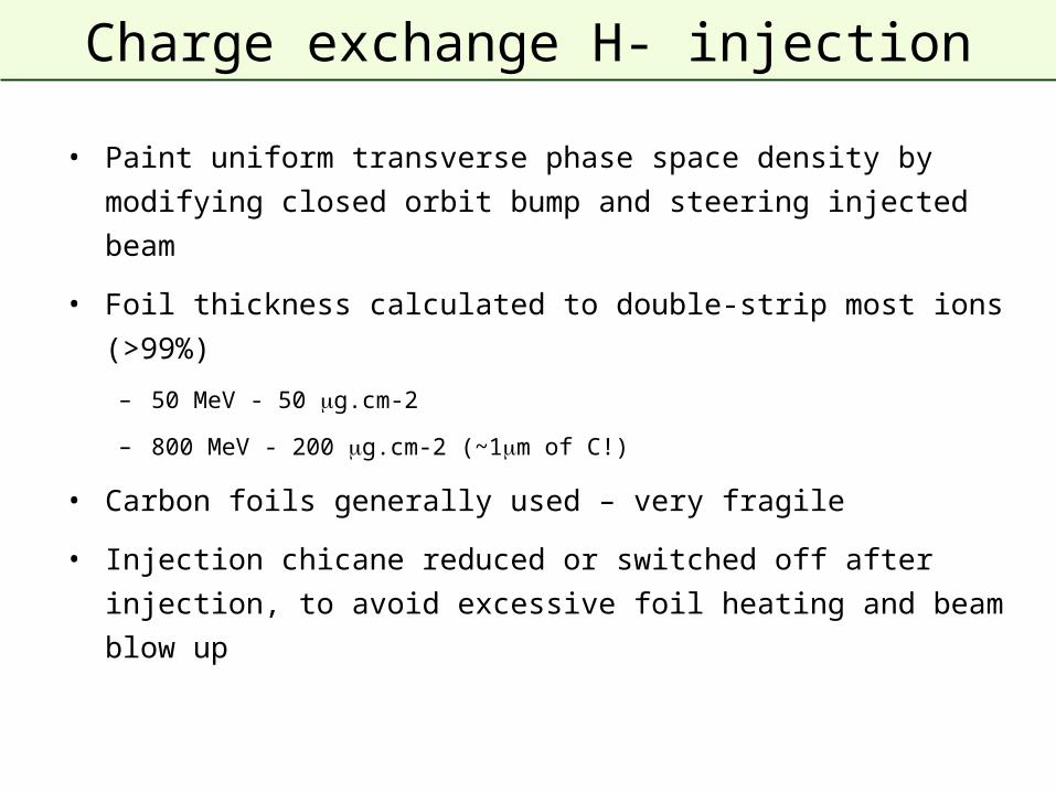
• Paint uniform transverse phase space density by modifying closed
orbit bump and steering injected beam
• Foil thickness calculated to double-strip most ions (>99%)
– 50 MeV - 50 g.cm-2
– 800 MeV - 200 g.cm-2 (~1m of C!)
• Carbon foils generally used – very fragile
• Injection chicane reduced or switched off after injection, to avoid
excessive foil heating and beam blow up
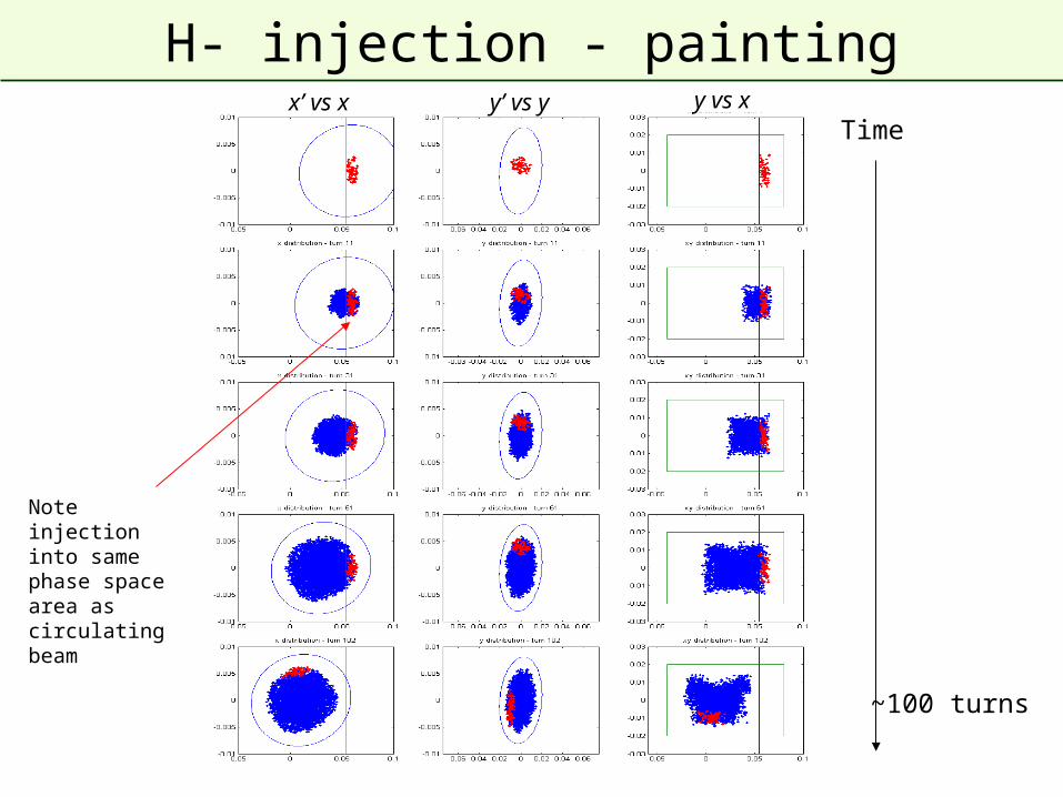
H- injection - painting
Timex’ vs x y’ vs y y vs x
Note injection into same phase space area as circulating beam
~100 turns
Lepton injection
• Single-turn injection can be used as for hadrons; however, lepton
motion is strongly damped (different with respect to proton or ion
injection).
– Synchrotron radiation
• Can use transverse or longitudinal damping:
– Transverse - Betatron accumulation
– Longitudinal - Synchrotron accumulation
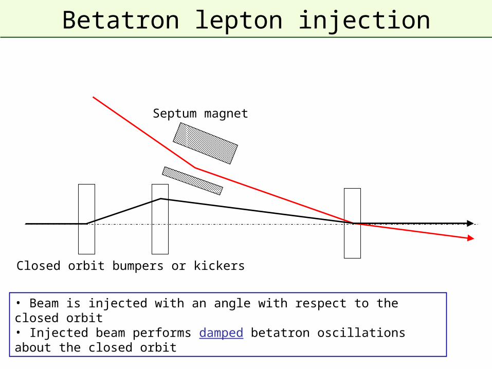
Betatron lepton injection
• Beam is injected with an angle with respect to the closed orbit • Injected beam performs damped betatron oscillations about the closed orbit
Septum magnet
Closed orbit bumpers or kickers
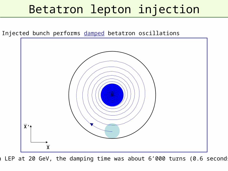
Betatron lepton injection
Injected bunch performs damped betatron oscillations
In LEP at 20 GeV, the damping time was about 6’000 turns (0.6 seconds)
X
'X
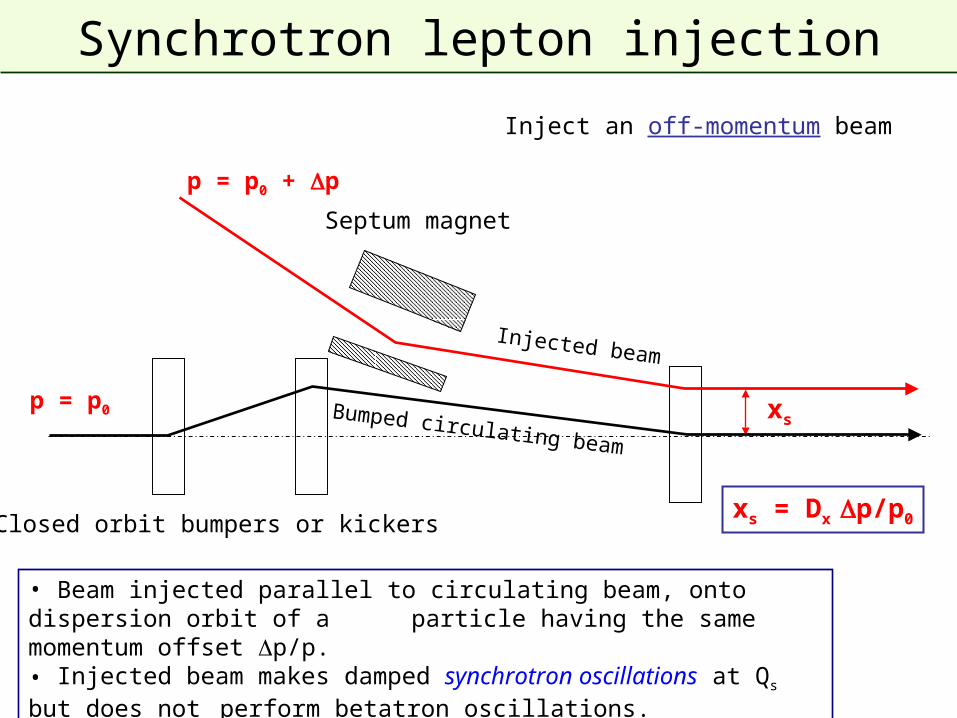
Synchrotron lepton injection
Septum magnet
• Beam injected parallel to circulating beam, onto dispersion orbit of a particle having the same momentum offset p/p.• Injected beam makes damped synchrotron oscillations at Qs but does not
perform betatron oscillations.
Closed orbit bumpers or kickers
Bumped circulating beam
Injected beam
xs = Dx p/p0
xsp = p0
p = p0 + p
Inject an off-momentum beam
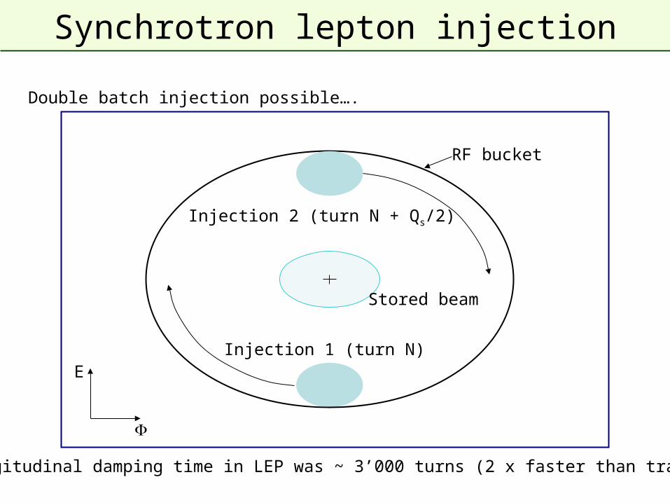
Synchrotron lepton injection
E
Double batch injection possible….
Longitudinal damping time in LEP was ~ 3’000 turns (2 x faster than transverse)
Injection 1 (turn N)
Injection 2 (turn N + Qs/2)
Stored beam
RF bucket
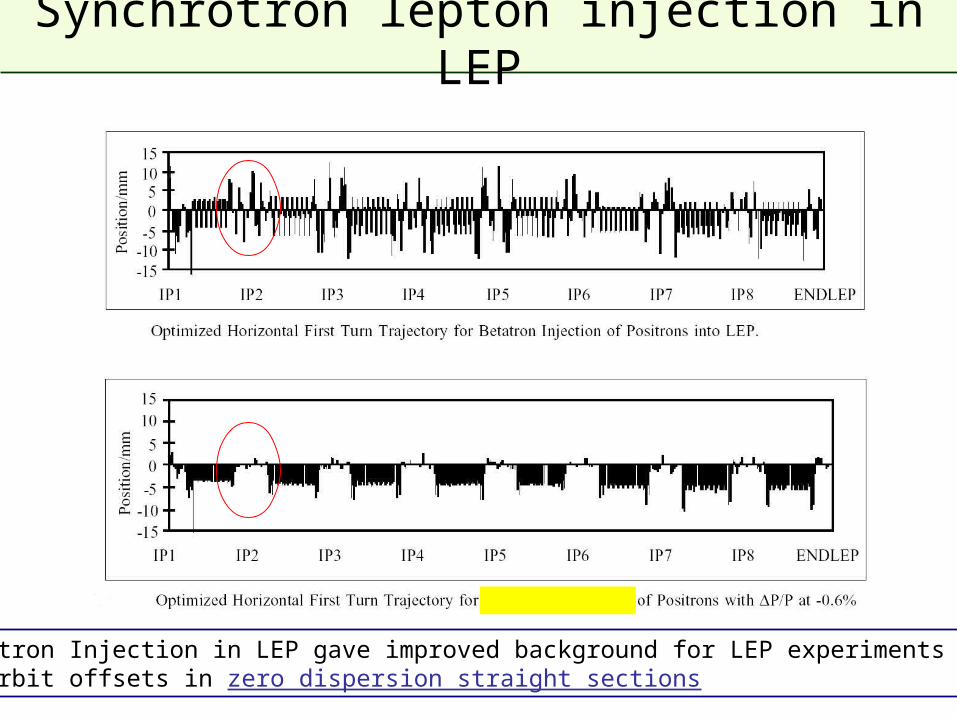
Synchrotron lepton injection in LEP
Synchrotron Injection in LEP gave improved background for LEP experiments due to small orbit offsets in zero dispersion straight sections
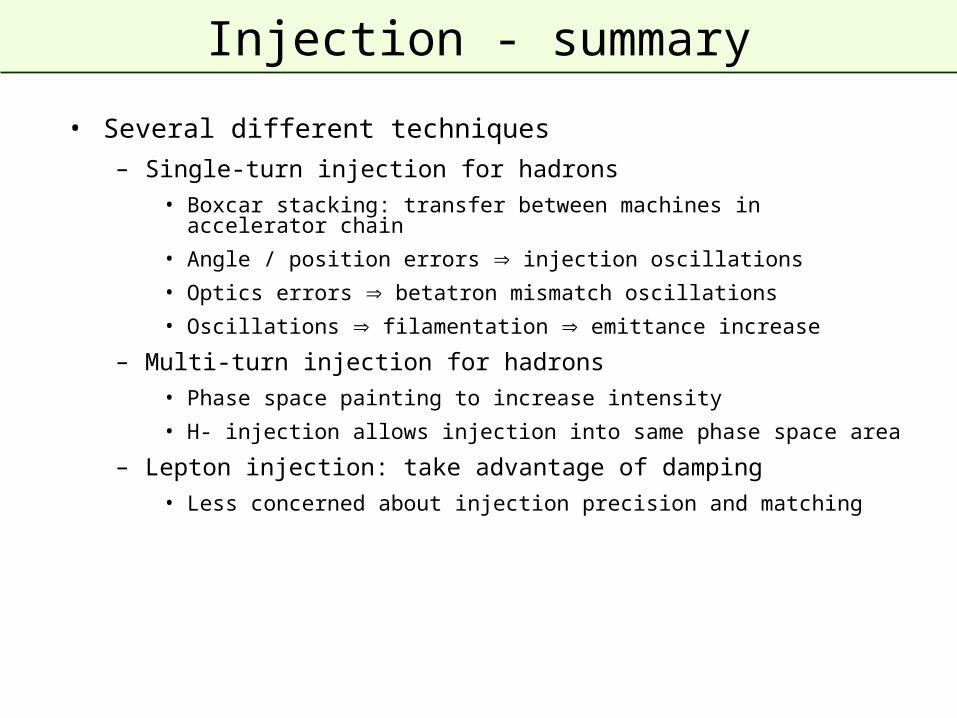
Injection - summary
• Several different techniques
– Single-turn injection for hadrons
• Boxcar stacking: transfer between machines in accelerator chain
• Angle / position errors injection oscillations
• Optics errors betatron mismatch oscillations
• Oscillations filamentation emittance increase
– Multi-turn injection for hadrons
• Phase space painting to increase intensity
• H- injection allows injection into same phase space area
– Lepton injection: take advantage of damping
• Less concerned about injection precision and matching
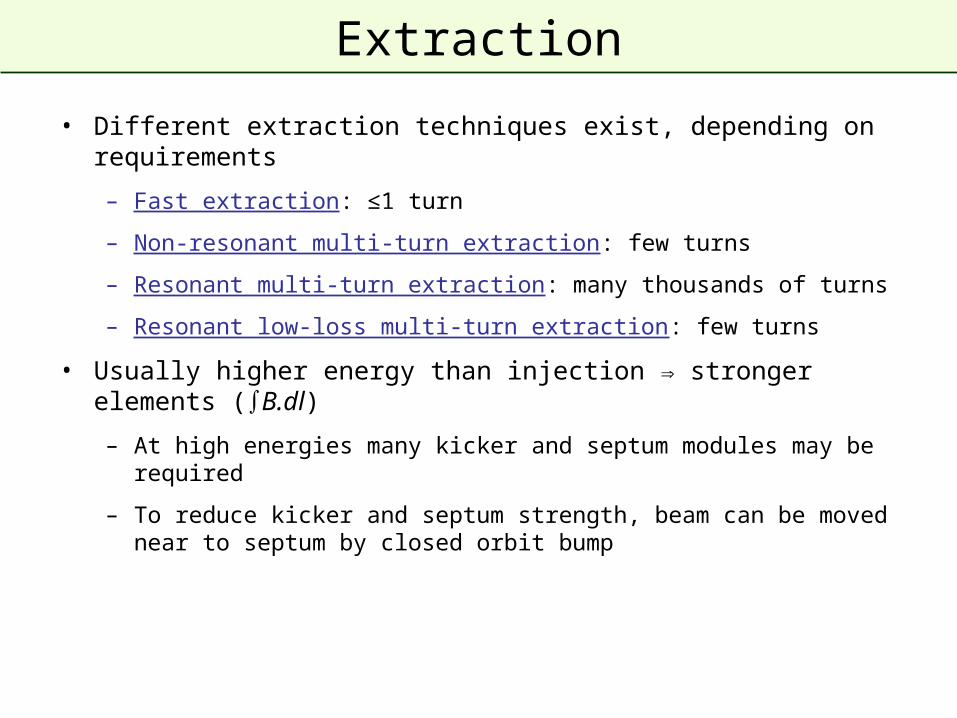
Extraction
• Different extraction techniques exist, depending on requirements
– Fast extraction: ≤1 turn
– Non-resonant multi-turn extraction: few turns
– Resonant multi-turn extraction: many thousands of turns
– Resonant low-loss multi-turn extraction: few turns
• Usually higher energy than injection stronger elements (∫B.dl)
– At high energies many kicker and septum modules may be required
– To reduce kicker and septum strength, beam can be moved near to septum by closed orbit bump
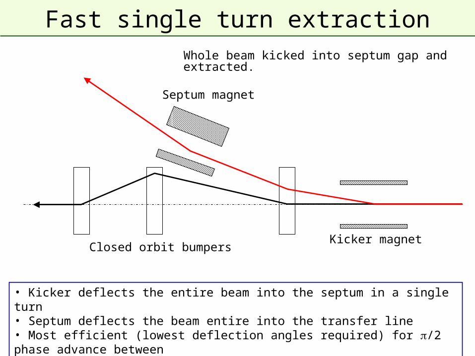
Fast single turn extraction
Septum magnet
Kicker magnet
• Kicker deflects the entire beam into the septum in a single turn• Septum deflects the beam entire into the transfer line• Most efficient (lowest deflection angles required) for /2 phase advance between kicker and septum
Closed orbit bumpers
Whole beam kicked into septum gap and extracted.
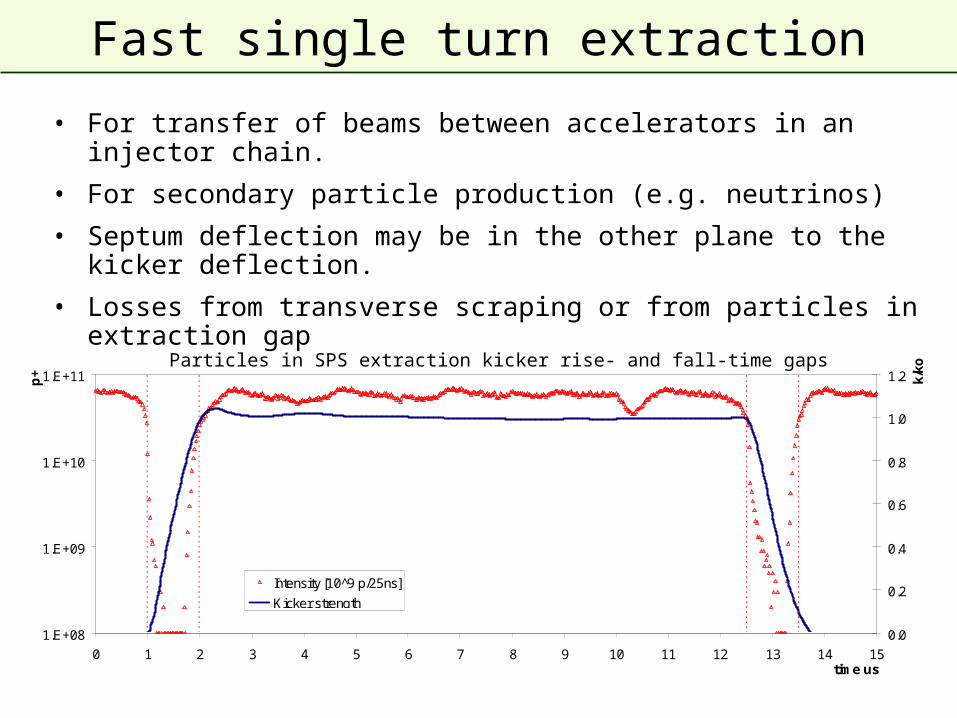
Fast single turn extraction
• For transfer of beams between accelerators in an injector chain.
• For secondary particle production (e.g. neutrinos)
• Septum deflection may be in the other plane to the kicker deflection.
• Losses from transverse scraping or from particles in extraction gap
1.E+08
1.E+09
1.E+10
1.E+11
0 1 2 3 4 5 6 7 8 9 10 11 12 13 14 15time us
p+
0.0
0.2
0.4
0.6
0.8
1.0
1.2 k/k
o
Intensity [10^9 p/25ns]
Kicker strength
Particles in SPS extraction kicker rise- and fall-time gaps
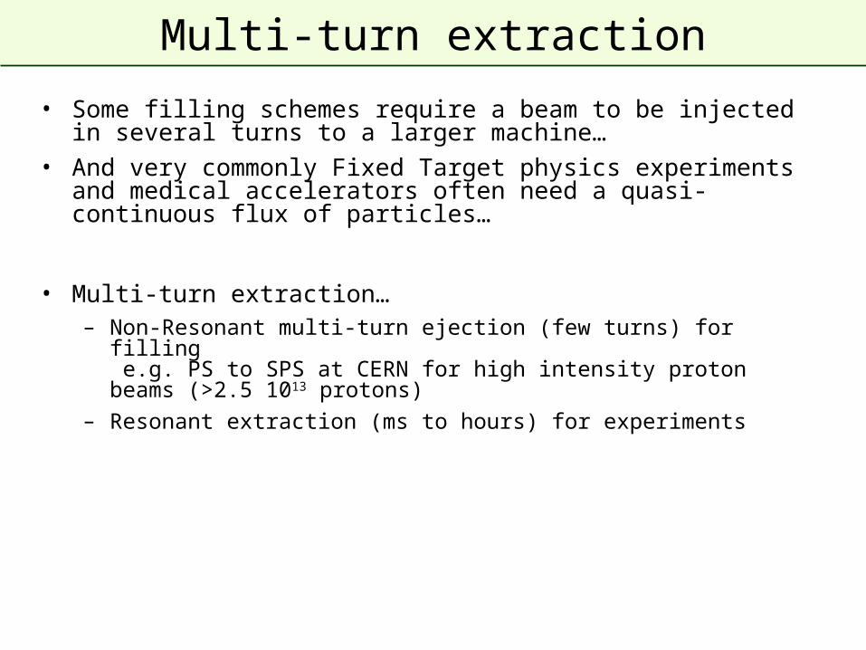
Multi-turn extraction
• Some filling schemes require a beam to be injected in several turns to a larger machine…
• And very commonly Fixed Target physics experiments and medical accelerators often need a quasi-continuous flux of particles…
• Multi-turn extraction…– Non-Resonant multi-turn ejection (few turns) for filling
e.g. PS to SPS at CERN for high intensity proton beams (>2.5 1013 protons)
– Resonant extraction (ms to hours) for experiments
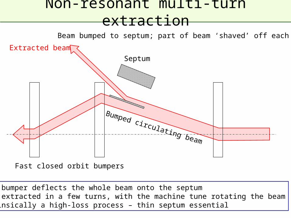
Extracted beam
Bumped circulating beam
Septum
• Fast bumper deflects the whole beam onto the septum• Beam extracted in a few turns, with the machine tune rotating the beam• Intrinsically a high-loss process – thin septum essential
Non-resonant multi-turn extraction
Fast closed orbit bumpers
Beam bumped to septum; part of beam ‘shaved’ off each turn.
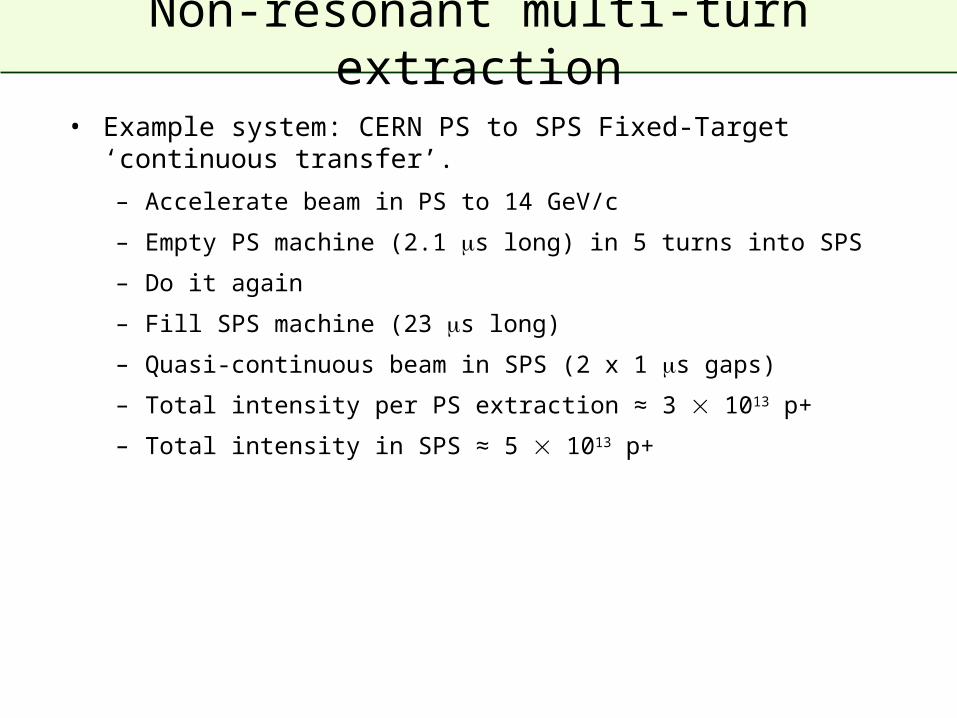
Non-resonant multi-turn extraction
• Example system: CERN PS to SPS Fixed-Target ‘continuous transfer’.
– Accelerate beam in PS to 14 GeV/c
– Empty PS machine (2.1 s long) in 5 turns into SPS
– Do it again
– Fill SPS machine (23 s long)
– Quasi-continuous beam in SPS (2 x 1 s gaps)
– Total intensity per PS extraction ≈ 3 1013 p+
– Total intensity in SPS ≈ 5 1013 p+
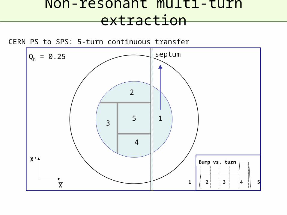
Non-resonant multi-turn extraction
X
'X
CERN PS to SPS: 5-turn continuous transfer
Qh = 0.25
1 2 3 4 5
Bump vs. turn
1
2
3
4
5
septum
Non-resonant multi-turn extraction
X
'X
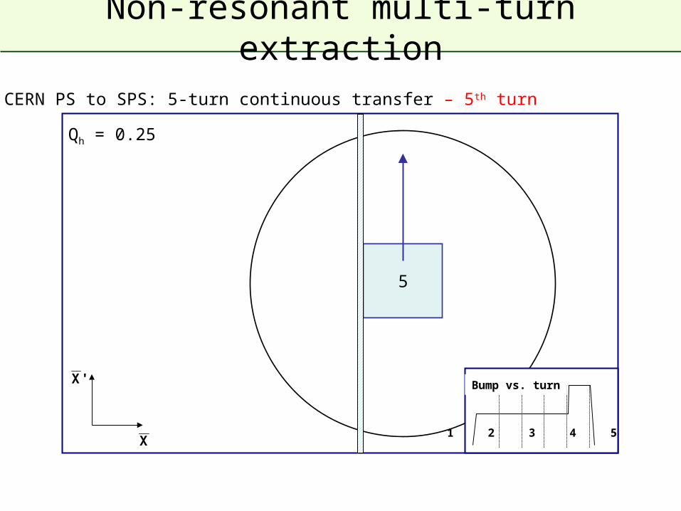
CERN PS to SPS: 5-turn continuous transfer – 5th turn
Qh = 0.25
1 2 3 4 5
Bump vs. turn
5
Non-resonant multi-turn extraction
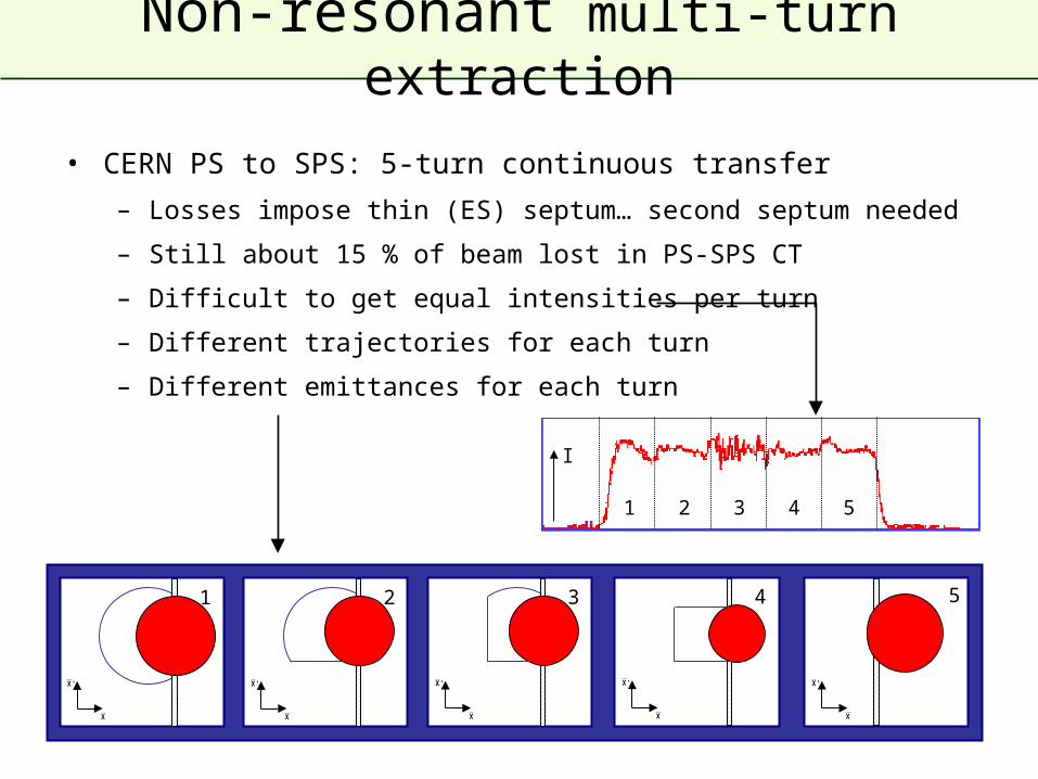
• CERN PS to SPS: 5-turn continuous transfer
– Losses impose thin (ES) septum… second septum needed
– Still about 15 % of beam lost in PS-SPS CT
– Difficult to get equal intensities per turn
– Different trajectories for each turn
– Different emittances for each turn
X
'X
1
X
'X
2
X
'X
3
X
'X
4
X
'X
5
I
1 2 3 4 5
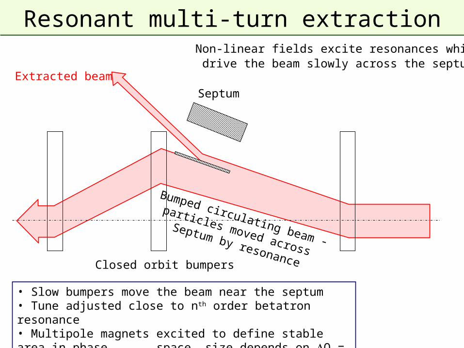
Extracted beam
Bumped circulating beam -
particles moved across
Septum by resonance
Septum
• Slow bumpers move the beam near the septum• Tune adjusted close to nth order betatron resonance• Multipole magnets excited to define stable area in phase space, size depends on Q = Q - Qr
Resonant multi-turn extraction
Closed orbit bumpers
Non-linear fields excite resonances which drive the beam slowly across the septum.
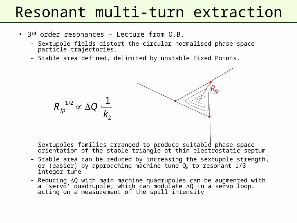
Resonant multi-turn extraction• 3rd order resonances – Lecture from O.B.
– Sextupole fields distort the circular normalised phase space particle trajectories.
– Stable area defined, delimited by unstable Fixed Points.
– Sextupoles families arranged to produce suitable phase space orientation of the stable triangle at thin electrostatic septum
– Stable area can be reduced by increasing the sextupole strength, or (easier) by approaching machine tune Qh to resonant 1/3 integer tune
– Reducing Q with main machine quadrupoles can be augmented with a ‘servo’ quadrupole, which can modulate Q in a servo loop, acting on a measurement of the spill intensity
2
2/1 1
kQR fp
Rfp
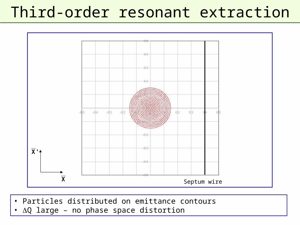
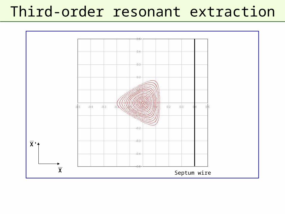
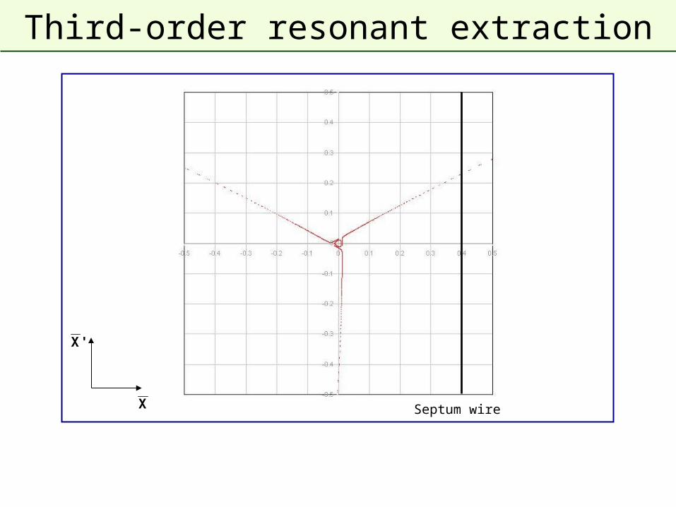
Third-order resonant extraction
• Particles distributed on emittance contours• Q large – no phase space distortion
X
'X
Septum wire
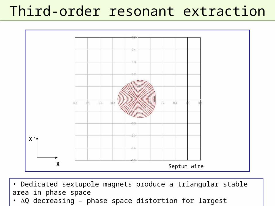
Third-order resonant extraction
• Dedicated sextupole magnets produce a triangular stable area in phase space• Q decreasing – phase space distortion for largest amplitudes
X
'X
Septum wire
Third-order resonant extraction
X
'X
Septum wire
Third-order resonant extraction
X
'X
Septum wire
Third-order resonant extraction
X
'X
Septum wire
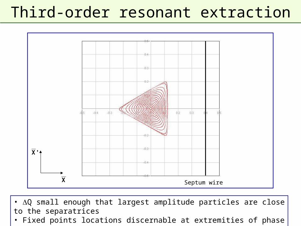
Third-order resonant extraction
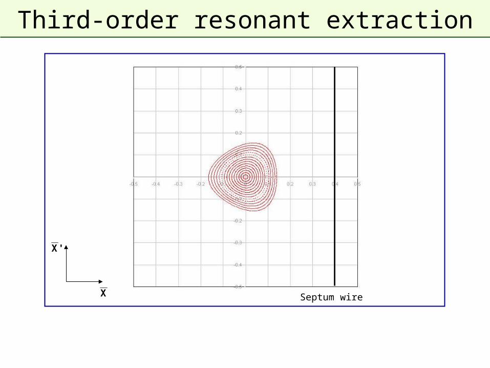
• Q small enough that largest amplitude particles are close to the separatrices• Fixed points locations discernable at extremities of phase space triangle
X
'X
Septum wire
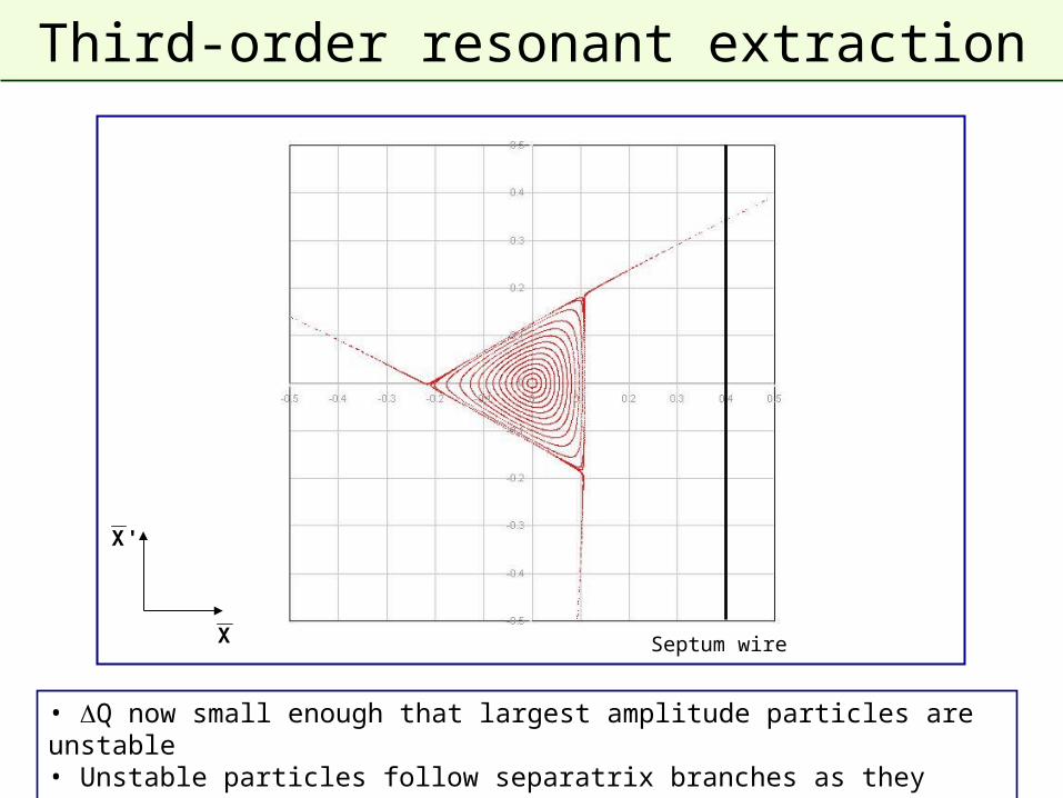
Third-order resonant extraction
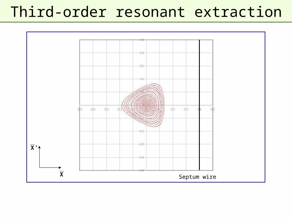
• Q now small enough that largest amplitude particles are unstable• Unstable particles follow separatrix branches as they increase in amplitude
X
'X
Septum wire
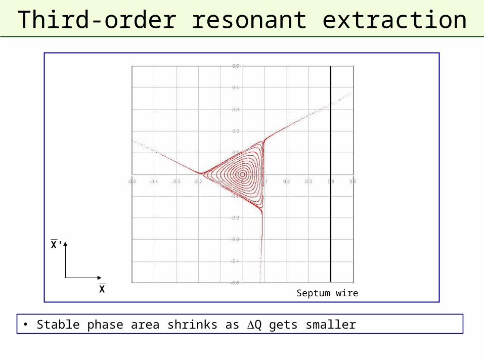
Third-order resonant extraction
• Stable phase area shrinks as Q gets smaller
X
'X
Septum wire
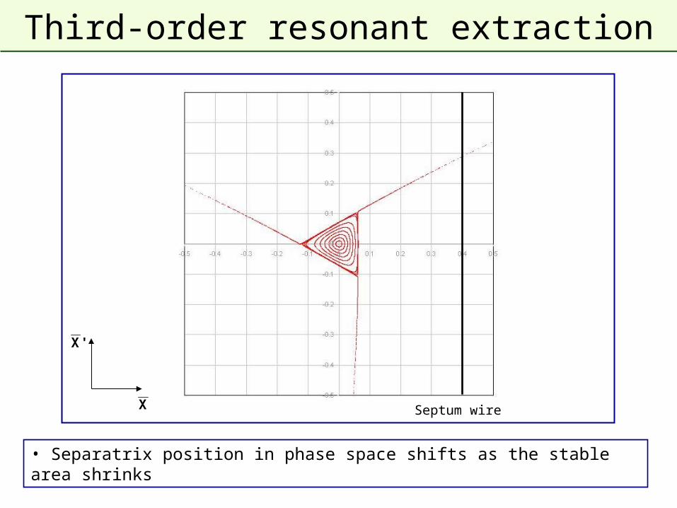
Third-order resonant extraction
• Separatrix position in phase space shifts as the stable area shrinks
X
'X
Septum wire
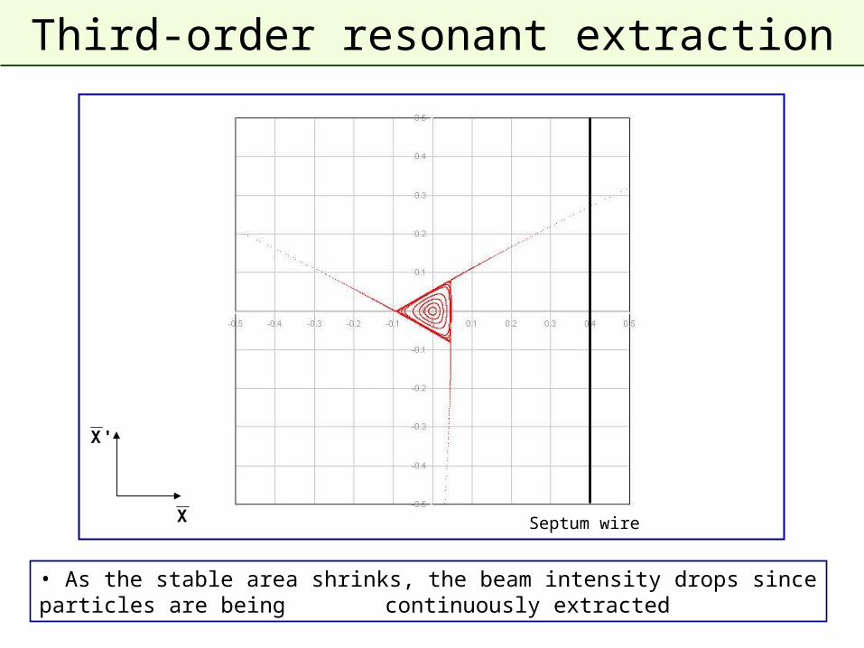
Third-order resonant extraction
• As the stable area shrinks, the beam intensity drops since particles are being continuously extracted
X
'X
Septum wire
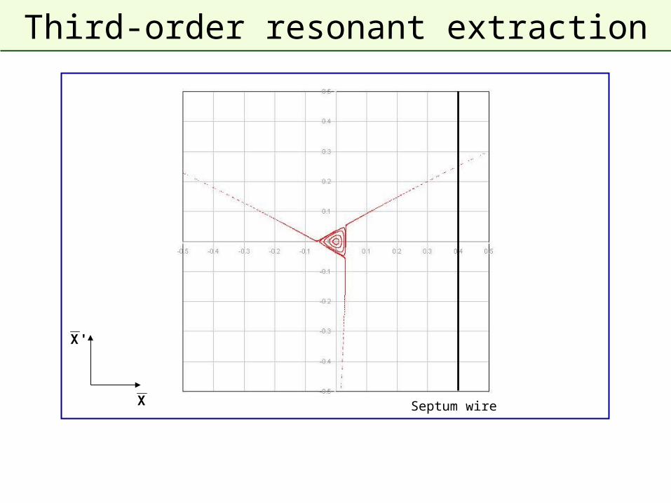
Third-order resonant extraction
X
'X
Septum wire
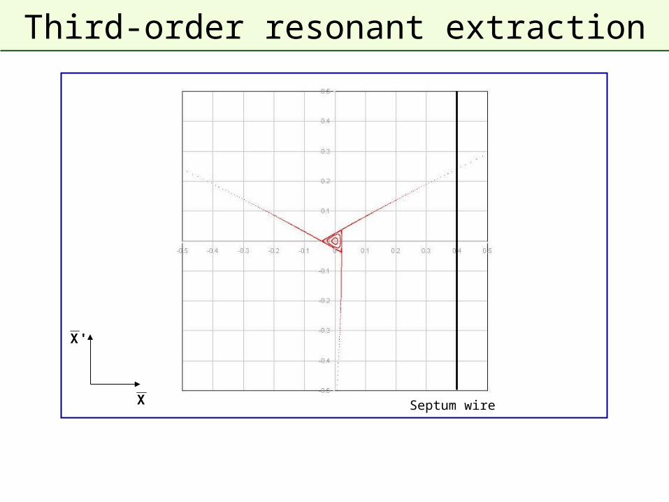
Third-order resonant extraction
X
'X
Septum wire
Third-order resonant extraction
X
'X
Septum wire
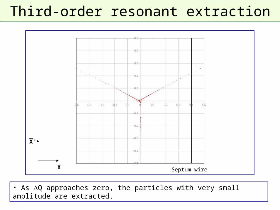
Third-order resonant extraction
• As Q approaches zero, the particles with very small amplitude are extracted.
X
'X
Septum wire
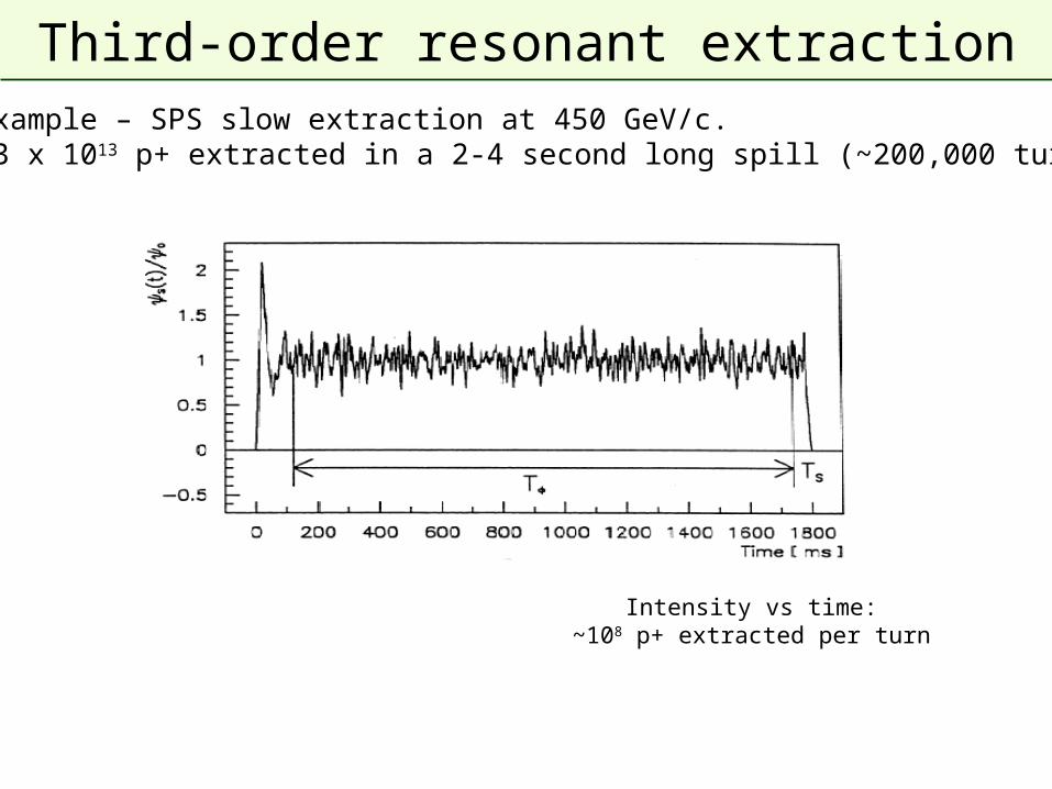
Third-order resonant extractionExample – SPS slow extraction at 450 GeV/c.~3 x 1013 p+ extracted in a 2-4 second long spill (~200,000 turns)
Intensity vs time:~108 p+ extracted per turn
Second-order resonant extraction
• An extraction can also be made over a few hundred turns
• 2nd and 4th order resonances
– Octupole fields distort the regular phase space particle trajectories.
– Stable area defined, delimited by two unstable Fixed Points.
– Beam tune brought across a 2nd order resonance (Q→0.5)
– Particle amplitudes quickly grow and beam is extracted in a few hundred turns.
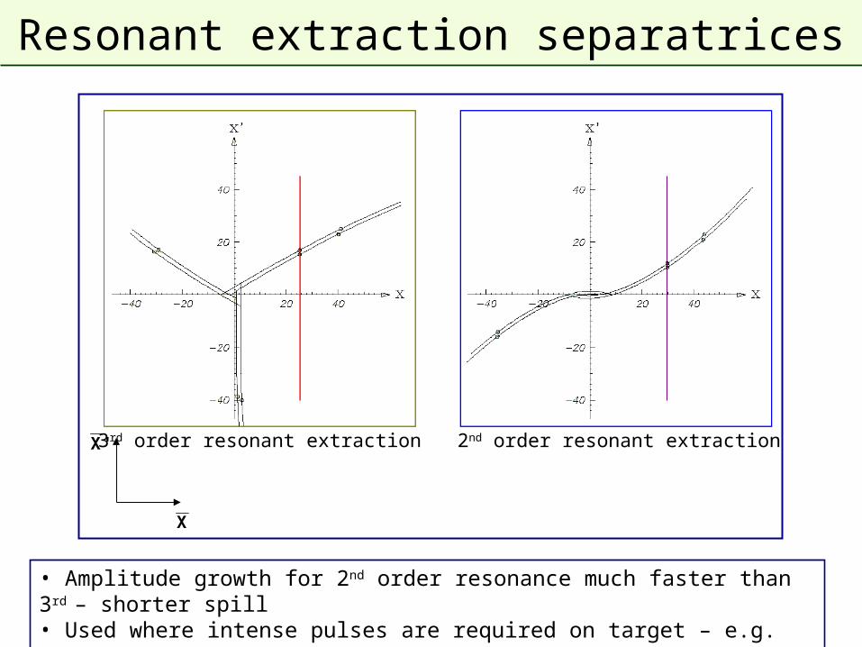
Resonant extraction separatrices
• Amplitude growth for 2nd order resonance much faster than 3rd – shorter spill• Used where intense pulses are required on target – e.g. neutrino production
X
'X 3rd order resonant extraction 2nd order resonant extraction
Resonant low-loss multi-turn extraction
• Adiabatic capture of beam in stable “islands”
– Use non-linear fields (sextupoles and octupoles) to create islands of stability in phase space
– A slow (adiabatic) tune variation to cross a resonance and to drive particles into the islands (capture)
– Variation of field strengths to separate the islands in phase space
• Several big advantages
– Losses reduced virtually to zero (no particles at the septum)
– Phase space matching improved with respect to existing non-resonant multi-turn extraction - all ‘beamlets’ have same emittance and optical parameters
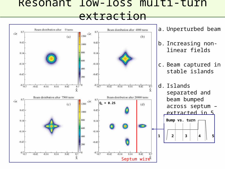
Resonant low-loss multi-turn extraction
Septum wire
a. Unperturbed beam
b. Increasing non-linear fields
c. Beam captured in stable islands
d. Islands separated and beam bumped across septum – extracted in 5 turns
1 2 3 4 5
Bump vs. turn
Qh = 0.25
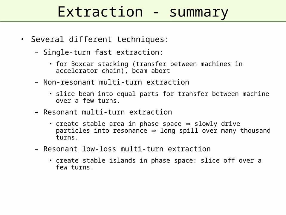
Extraction - summary
• Several different techniques:
– Single-turn fast extraction:
• for Boxcar stacking (transfer between machines in accelerator chain), beam abort
– Non-resonant multi-turn extraction
• slice beam into equal parts for transfer between machine over a few turns.
– Resonant multi-turn extraction
• create stable area in phase space slowly drive particles into resonance long spill over many thousand turns.
– Resonant low-loss multi-turn extraction
• create stable islands in phase space: slice off over a few turns.