Embed Size (px)
Citation preview

353
Inkjet Printing Resolution Study
for Multi-Material Rapid Prototyping∗
Mustaffa IBRAHIM∗∗, Takayuki OTSUBO∗∗, Hiroyuki NARAHARA∗∗,Hiroshi KORESAWA∗∗ and Hiroshi SUZUKI∗∗
In addition to its application in media printing, inkjet printing is becoming an increas-ingly attractive option for the distribution and patterning of materials for a wide variety ofapplications. In this study a commercial inkjet printer was modified to study the resolution offluid dot placement required to fabricate 3D multi-material patterns layer by layer. A Java-based computer program was developed to convert stereolithography (STL) data layer bylayer, control ink cartridges individually and print ink with customized fluid dot placementarrangements. The study found that complement printing between nozzles which are 30 µmin diameter and 144 µm apart is essential to achieve a sufficiently dense 3D pattern. Whenprinted with 36 µm vertical spacing a layer thickness of 1.30 µm is achievable, and whenprinting layer by layer, the thickness increases almost at a linear rate.
Key Words: Rapid Prototyping, Inkjet Printing, Multi-Material, Resolution, Positioning
1. Introduction
The advancement of manufacturing technologies isbeing driven by the need for automation, miniaturization,cost reduction and environmentally friendly manufactur-ing. The prospect of adopting inkjet printing technology invarious advanced manufacturing processes is very promis-ing. With this broader view of the technologies encom-passed by the term “inkjet printing”, applications in elec-tronics, optics, displays, virtual reality, medical diagnos-tics, and medical procedures have been developed usinginkjet fluid microdispensing as an enabling technology(1).This study intends to utilize a Java program to manipu-late CAD design data and interface them with a modi-fied commercial 357-nozzle piezoelectric printer to pro-duce 3D patterns, as shown in Fig. 1.
1. 1 Fabricating 3D structure using inkjet printingRecently a rapid prototyping method for building
parts layer by layer has led to interest in fabrication ofelectrical circuits and optical devices by inkjet printing.The classic definition of rapid prototyping is “a specialclass of machine technology that quickly produces mod-
∗ Received 28th October, 2005 (No. 05-4226)∗∗ Department of Mechanical Information Science and Tech-
nology, Kyushu Institute of Technology, 680–4 Kawazu,Iizuka-shi, Fukuoka 820–8502, Japan.E-mail: [email protected]
els and prototype parts from 3D data using an additiveapproach to form the physical models”(2). The charac-teristic feature of the inkjet process is to print dots, butfor printing multi-material 3D functional parts, lines andareas with good dot-to-dot conductivity are a necessity,as for example in electrical and thermal conduction ap-plications. An inkjet printer patterns material by eject-ing tiny droplets of liquid ink from its printhead noz-zles or orifices as it moves in two dimensions approxi-mately 1 mm above a substrate. The advantages of inkjettechnology are straightforward: its apparent simplicity,the fact that it is data-driven, its high material depositionspeed, reduced waste of costly materials, and eliminationof cross-contamination on surfaces because it is a non-contact process. The overall size of the particles that canbe jetted are limited by the diameter of the nozzle exit ori-
Fig. 1 Piezoelectric printhead configuration
JSME International Journal Series C, Vol. 49, No. 2, 2006
354
Fig. 2 Single channel drop-on-demand dispensing deviceconfiguration
fice diameter, and line width/thickness is determined bythe jetted liquid properties and the orifice diameter(3).
1. 2 Related studiesAlthough there is already ongoing research into using
inkjet printing to build MEMS, organic displays, and bio-logical arrays(4), (5), most systems use a drop-on-demandplatform that has a single-nozzle piezoelectric-actuateddevice, such as that from MicroFab Technologies Inc.(6),to direct write materials, as denoted in Fig. 2. The Z Corp.rapid prototyping machine, which uses 3D printing tech-nology originally developed at the Massachusetts Insti-tute of Technology, has traditionally used plaster and resinpowders onto which an inkjet printer sprays glue to createsolid prototypes, and cellulose fiber bound with an adhe-sive for creating models used for investment and sand cast-ings(7). Objet Geometries Ltd. has successfully inkjet pho-topolymer to create models, using multiple nozzles to jetlayer on layer of photopolymer, with each layer cured im-mediately by exposure to UV light(8). Even though inkjetprinting technology has been used to fabricate 3D struc-tures or models, parts produced by the commercially avail-able rapid prototyping systems are made of a single mate-rial. The multi-color 3D printer from Z Corp. only printscolors on surfaces — the material beneath is still the sameas the modeling material. In other rapid prototyping sys-tems, various parts are built independently using differentcolors and then assembled at a later stage. A new sys-tem is expected which can produce assemblies composedof parts with more than one color or with more than onematerial(9). With this capability, some post-processing ofrapid prototyping such as assembly, bonding, welding andpainting can be eliminated. Drop-on-demand inkjet tech-nology is among the rapid prototyping methods that canbe extended to build multi-material assembly by addingmore material inkjet nozzles to deposit materials selec-tively, layer by layer.
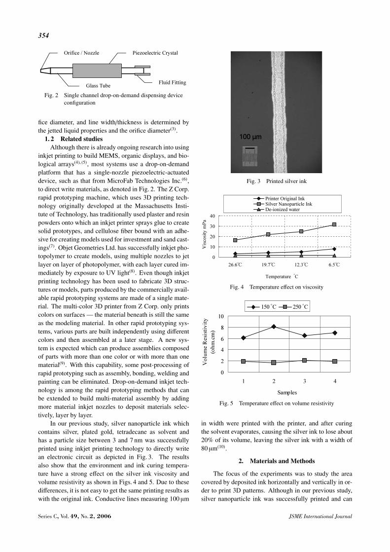
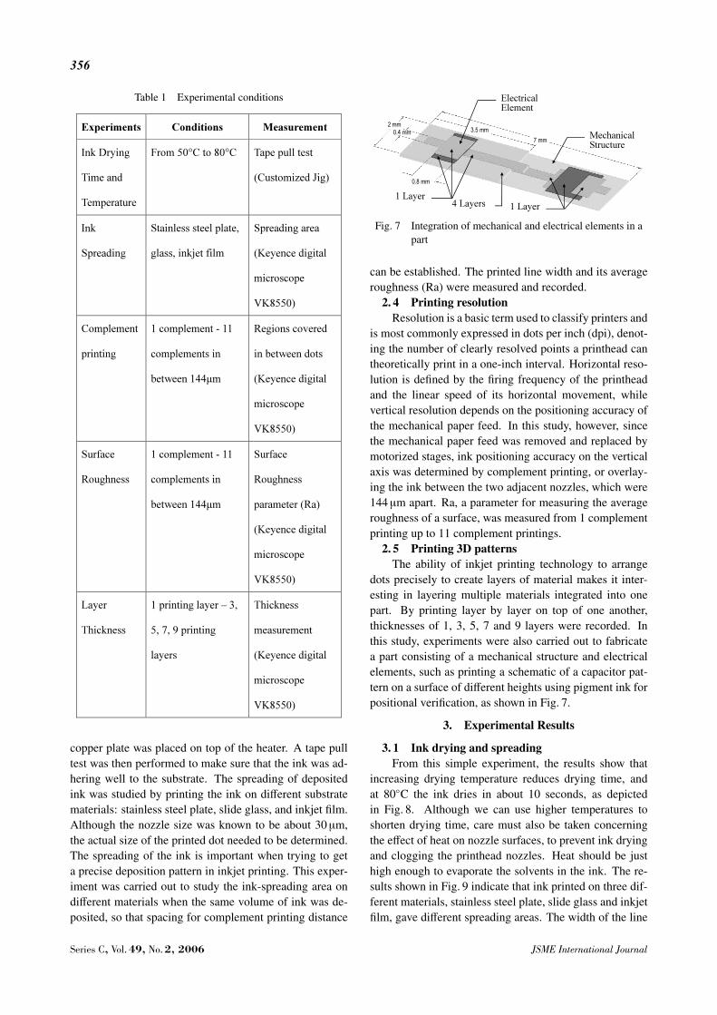
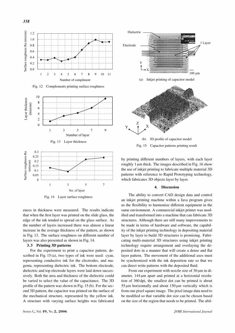
In our previous study, silver nanoparticle ink whichcontains silver, plated gold, tetradecane as solvent andhas a particle size between 3 and 7 nm was successfullyprinted using inkjet printing technology to directly writean electronic circuit as depicted in Fig. 3. The resultsalso show that the environment and ink curing tempera-ture have a strong effect on the silver ink viscosity andvolume resistivity as shown in Figs. 4 and 5. Due to thesedifferences, it is not easy to get the same printing results aswith the original ink. Conductive lines measuring 100 µm
Fig. 3 Printed silver ink
Fig. 4 Temperature effect on viscosity
Fig. 5 Temperature effect on volume resistivity
in width were printed with the printer, and after curingthe solvent evaporates, causing the silver ink to lose about20% of its volume, leaving the silver ink with a width of80 µm(10).
2. Materials and Methods
The focus of the experiments was to study the areacovered by deposited ink horizontally and vertically in or-der to print 3D patterns. Although in our previous study,silver nanoparticle ink was successfully printed and can
Series C, Vol. 49, No. 2, 2006 JSME International Journal

355
Fig. 6 Inkjet printing system
function as a conductive circuit, a more thorough under-standing of printer capabilities in arranging dots in boththe X and Y axis and in patterning 3D patterns needed tobe reached. A Java program was developed because oflimitations in using the window based printer driver soft-ware. Among the printer software limitations are:• Several nozzles will be depositing simultaneously
when image data was sent and this will create problem infabricating multi-material 3D structure.• The paper feeding mechanism distance movement
cannot be customized when complement printing is re-quired.• Synchronization between printing and motorized
stages cannot be done due to different operating window.The Java program developed in this study is capable to:• convert from CAD data to pixel image data• direct control the printer bypassing the printer soft-
ware• independently control the fluid cartridges selection• synchronize motorized stages and printing move-
mentThe present study used the printer’s original pigment
ink, with a surface tension of approximately 28.7 mN/mand viscosity at room temperature of approximately3.59 mPa(11). The ink cartridges were mounted on a com-mercially available desktop printer that was modified to becapable of fabricating 3D patterns layer by layer. The po-sitioning of deposited ink is important because failure todeposit ink in some areas would have a significant effectif functional inks such as conductive or magnetic ink wereto be used.
2. 1 Drop-on-demand inkjet systemsAmong the numerous types of inkjet technology, the
most common are drop-on-demand systems such as ther-mal and piezoelectric, which have dominated the lower-end printer market. In thermal inkjet technology, the dropis initiated by heating the ink to create a bubble until pres-
sure forces it to burst and hit the paper. However, thehigh temperatures may trigger problems or incompatibil-ities with certain functional ink formulations. The otherinkjet technology used in this study is from Epson, andutilizes a piezoelectric crystal positioned at the rear of theinkjet reservoir. When actuated, the piezoelectric crystalflexes and forces a drop of ink out of the nozzle(12).
2. 2 Experimental setupThis study used a Java program to slice rapid proto-
typing STL data and translate them to bitmap data layerby layer. The layer image was then sent to the printer,which was also controlled by the Java program, so thatit was feasible to choose the inkjet cartridge individuallyfor color selection and to avoid the color mixing processwhich the printer software would initiate under normal op-eration. The modified printer was equipped with motor-ized stages and a heater in order to fabricate 3D patterns.The inkjet printing system’s horizontal movement is notmodified, but the mechanical paper feed mechanism wasreplaced by motorized stages as depicted in Fig. 6. TheJava program synchronizes movement of the motorizedstages with the printer in order to fabricate 3D patternsidentical to the rapid prototyping concept. A film heaterwas placed on top of the stage to dry the deposited flu-ids and maintain their shape rather than allowing them tospread out on the surface, which would cause dots to in-teract with one another. The printer’s printhead nozzle isabout 30 µm in diameter and the distance between nozzlesis 144 µm. A summary of the conditions under which theexperiments were carried out is given in Table 1.
2. 3 Ink drying and spreadingFirst, the ink drying temperature had to be deter-
mined, because partial drying would cause the ink to ap-pear dry on the surface while trapping solvent underneath.A film heater was used, and the voltage supplying it wasvaried to ascertain the time and temperature required todry the ink. To make sure heat was evenly distributed, a
JSME International Journal Series C, Vol. 49, No. 2, 2006
356
Table 1 Experimental conditions
copper plate was placed on top of the heater. A tape pulltest was then performed to make sure that the ink was ad-hering well to the substrate. The spreading of depositedink was studied by printing the ink on different substratematerials: stainless steel plate, slide glass, and inkjet film.Although the nozzle size was known to be about 30 µm,the actual size of the printed dot needed to be determined.The spreading of the ink is important when trying to geta precise deposition pattern in inkjet printing. This exper-iment was carried out to study the ink-spreading area ondifferent materials when the same volume of ink was de-posited, so that spacing for complement printing distance
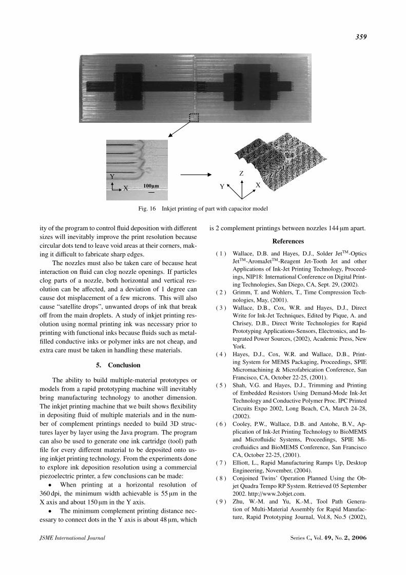
Fig. 7 Integration of mechanical and electrical elements in apart
can be established. The printed line width and its averageroughness (Ra) were measured and recorded.
2. 4 Printing resolutionResolution is a basic term used to classify printers and
is most commonly expressed in dots per inch (dpi), denot-ing the number of clearly resolved points a printhead cantheoretically print in a one-inch interval. Horizontal reso-lution is defined by the firing frequency of the printheadand the linear speed of its horizontal movement, whilevertical resolution depends on the positioning accuracy ofthe mechanical paper feed. In this study, however, sincethe mechanical paper feed was removed and replaced bymotorized stages, ink positioning accuracy on the verticalaxis was determined by complement printing, or overlay-ing the ink between the two adjacent nozzles, which were144 µm apart. Ra, a parameter for measuring the averageroughness of a surface, was measured from 1 complementprinting up to 11 complement printings.
2. 5 Printing 3D patternsThe ability of inkjet printing technology to arrange
dots precisely to create layers of material makes it inter-esting in layering multiple materials integrated into onepart. By printing layer by layer on top of one another,thicknesses of 1, 3, 5, 7 and 9 layers were recorded. Inthis study, experiments were also carried out to fabricatea part consisting of a mechanical structure and electricalelements, such as printing a schematic of a capacitor pat-tern on a surface of different heights using pigment ink forpositional verification, as shown in Fig. 7.
3. Experimental Results
3. 1 Ink drying and spreadingFrom this simple experiment, the results show that
increasing drying temperature reduces drying time, andat 80◦C the ink dries in about 10 seconds, as depictedin Fig. 8. Although we can use higher temperatures toshorten drying time, care must also be taken concerningthe effect of heat on nozzle surfaces, to prevent ink dryingand clogging the printhead nozzles. Heat should be justhigh enough to evaporate the solvents in the ink. The re-sults shown in Fig. 9 indicate that ink printed on three dif-ferent materials, stainless steel plate, slide glass and inkjetfilm, gave different spreading areas. The width of the line
Series C, Vol. 49, No. 2, 2006 JSME International Journal

357
Fig. 8 Drying time
Fig. 9 Ink spreading
printed on glass is less than that of ink printed on stainlesssteel plate and inkjet film. This shows that the ink spreadless on glass because its contact angle, which determinesits wetting, is greater than ink printed on the other sub-strates. The average roughness value of ink printed onglass is also lower than the other materials.
3. 2 Printing resolutionExperiments were carried out to establish a fully
dense deposition pattern by means of complement print-ing. Figure 10 (a) shows the result of printing withoutcomplement, with a gap of about 90 µm between the twoadjacent nozzles. After one complement printing, the gapwas still not fully covered by the ink, because the widthof a dot is only about 55 µm, as shown in Fig. 10 (b). Inorder to fully fill the gap between the two adjacent noz-zles a minimum of two complement printings 48 µm apartare necessary, as shown in Fig. 10 (c). With nozzle size30 µm in diameter, nozzles 144 µm apart, and printed ata horizontal resolution of 360 dpi, the smallest a dot canbe printed is about 55 µm horizontally and 150 µm verti-cally, which is from one pixel square image, as depicted inFig. 11. Overlay printing until there are 11 complementsbetween the two nozzles shows that the roughness of thesurface increases as more lines were printed with smallerprint spacing, as shown in Fig. 12.
For the layer thickness experiment, a 36 µm printspacing was used to print a square pattern, and differ-
(a) Without complements
(b) One complement
(c) Two complements
Fig. 10 Complement printing results
Fig. 11 Printing resolution
JSME International Journal Series C, Vol. 49, No. 2, 2006
358
Fig. 12 Complements printing surface roughness
Fig. 13 Layer thickness
Fig. 14 Layer surface roughness
ences in thickness were measured. The results indicatethat when the first layer was printed on the slide glass, theedge of the ink tended to spread on the glass surface. Asthe number of layers increased there was almost a linearincrease in the average thickness of the pattern, as shownin Fig. 13. The surface roughness on different number oflayers was also presented as shown in Fig. 14.
3. 3 Printing 3D patternsFor the experiment to print a capacitor pattern, de-
scribed in Fig. 15 (a), two types of ink were used: cyan,representing conductive ink for the electrodes, and ma-genta, representing dielectric ink. The bottom electrode,dielectric and top electrode layers were laid down succes-sively. Both the area and thickness of the dielectric couldbe varied to select the value of the capacitance. The 3Dprofile of the pattern was shown in Fig. 15 (b). For the sec-ond 3D pattern, the capacitor was printed on the surface ofthe mechanical structure, represented by the yellow ink.A structure with varying surface heights was fabricated
(a) Inkjet printing of capacitor model
(b) 3D profile of capacitor model
Fig. 15 Capacitor patterns printing result
by printing different numbers of layers, with each layerroughly 1 µm thick. The images described in Fig. 16 showthe use of inkjet printing to fabricate multiple material 3Dpatterns with reference to Rapid Prototyping technology,which fabricates 3D objects layer by layer.
4. Discussion
The ability to convert CAD design data and controlan inkjet printing machine within a Java program givesus the flexibility to harmonize different equipment in thesame environment. A commercial inkjet printer was mod-ified and transformed into a machine that can fabricate 3Dstructures. Although there are still many improvements tobe made in terms of hardware and software, the capabil-ity of the inkjet printing technology in depositing materiallayer by layer to build 3D structures is promising. Fabri-cating multi-material 3D structures using inkjet printingtechnology require arrangement and overlaying the de-posited dots in a manner that will create a dense and flatlayer pattern. The movement of the additional axes mustbe synchronized with the ink deposition rate so that wecan direct write patterns with the deposited fluid.
From our experiment with nozzle size of 30 µm in di-ameter, 144 µm apart and printed at a horizontal resolu-tion of 360 dpi, the smallest dot can be printed is about55 µm horizontally and about 150 µm vertically which isfrom one pixel square image. The pixel image data need tobe modified so that variable dot size can be chosen basedon the size of the region that needs to be printed. The abil-
Series C, Vol. 49, No. 2, 2006 JSME International Journal
359
Fig. 16 Inkjet printing of part with capacitor model
ity of the program to control fluid deposition with differentsizes will inevitably improve the print resolution becausecircular dots tend to leave void areas at their corners, mak-ing it difficult to fabricate sharp edges.
The nozzles must also be taken care of because heatinteraction on fluid can clog nozzle openings. If particlesclog parts of a nozzle, both horizontal and vertical res-olution can be affected, and a deviation of 1 degree cancause dot misplacement of a few microns. This will alsocause “satellite drops”, unwanted drops of ink that breakoff from the main droplets. A study of inkjet printing res-olution using normal printing ink was necessary prior toprinting with functional inks because fluids such as metal-filled conductive inks or polymer inks are not cheap, andextra care must be taken in handling these materials.
5. Conclusion
The ability to build multiple-material prototypes ormodels from a rapid prototyping machine will inevitablybring manufacturing technology to another dimension.The inkjet printing machine that we built shows flexibilityin depositing fluid of multiple materials and in the num-ber of complement printings needed to build 3D struc-tures layer by layer using the Java program. The programcan also be used to generate one ink cartridge (tool) pathfile for every different material to be deposited onto us-ing inkjet printing technology. From the experiments doneto explore ink deposition resolution using a commercialpiezoelectric printer, a few conclusions can be made:• When printing at a horizontal resolution of
360 dpi, the minimum width achievable is 55 µm in theX axis and about 150 µm in the Y axis.• The minimum complement printing distance nec-
essary to connect dots in the Y axis is about 48 µm, which
is 2 complement printings between nozzles 144 µm apart.
References
( 1 ) Wallace, D.B. and Hayes, D.J., Solder JetTM-OpticsJetTM-AromaJetTM-Reagent Jet-Tooth Jet and otherApplications of Ink-Jet Printing Technology, Proceed-ings, NIP18: International Conference on Digital Print-ing Technologies, San Diego, CA, Sept. 29, (2002).
( 2 ) Grimm, T. and Wohlers, T., Time Compression Tech-nologies, May, (2001).
( 3 ) Wallace, D.B., Cox, W.R. and Hayes, D.J., DirectWrite for Ink-Jet Techniques, Edited by Pique, A. andChrisey, D.B., Direct Write Technologies for RapidPrototyping Applications-Sensors, Electronics, and In-tegrated Power Sources, (2002), Academic Press, NewYork.
( 4 ) Hayes, D.J., Cox, W.R. and Wallace, D.B., Print-ing System for MEMS Packaging, Proceedings, SPIEMicromachining & Microfabrication Conference, SanFrancisco, CA, October 22-25, (2001).
( 5 ) Shah, V.G. and Hayes, D.J., Trimming and Printingof Embedded Resistors Using Demand-Mode Ink-JetTechnology and Conductive Polymer Proc. IPC PrintedCircuits Expo 2002, Long Beach, CA, March 24-28,(2002).
( 6 ) Cooley, P.W., Wallace, D.B. and Antohe, B.V., Ap-plication of Ink-Jet Printing Technology to BioMEMSand Microfluidic Systems, Proceedings, SPIE Mi-crofluidics and BioMEMS Conference, San FranciscoCA, October 22-25, (2001).
( 7 ) Elliott, L., Rapid Manufacturing Ramps Up, DesktopEngineering, November, (2004).
( 8 ) Conjoined Twins’ Operation Planned Using the Ob-jet Quadra Tempo RP System. Retrieved 05 September2002. http://www.2objet.com.
( 9 ) Zhu, W.-M. and Yu, K.-M., Tool Path Genera-tion of Multi-Material Assembly for Rapid Manufac-ture, Rapid Prototyping Journal, Vol.8, No.5 (2002),
JSME International Journal Series C, Vol. 49, No. 2, 2006

360
pp.277–283.(10) Mustaffa, B.I., Narahara, H., Koresawa, H. and Suzuki,
H., Integration of Silver Nanoparticle Inkjet Printingand Layered Manufacturing Technology, Proc the 7th.Intl. Conf. Quality in Research (QIR) 2004 (Mech.Engineering), ME-DM-04-1-4, Jakarta, Indonesia, Au-gust, (2004).
(11) Mustaffa, B.I., Narahara, H. and Suzuki, H., Elec-tronic Circuit Fabrication Using Inkjet Printed SilverNanoparticles for SFF, Proc. of Japan Society for Preci-
sion Engineering National Conference, Tokyo, (2004),pp.83–84.
(12) McGill, R.A., Ringeisen, B. and Wu, P.K., The Role ofDirect Writing for Chemical and Biological Materials:Commercial & Military Sensing Applications, Editedby Pique, A. and Chrisey, D.B., Direct Write Technolo-gies for Rapid Prototyping Applications-Sensors, Elec-tronics, and Integrated Power Sources, (2002), Aca-demic Press, New York.
Series C, Vol. 49, No. 2, 2006 JSME International Journal