Embed Size (px)
Citation preview

Innovation in Mobility Shortcut to WINWORD.EXE.lnk
06/04/04 92-2004 RICON CORPORATIONAll Rights Reserved
Printed in the United States of America
32DSSP02.C U.S. Patent Nos: 4,534,450; 5,308,215; 5,445,488; 5,605,431; 5,944,473;
Australia Patent Nos: 661127; 687066; Canadian Patent Nos: 1,245,603; 2,168,761
Other U.S. and foreign patents pending
S-Series Personal Use
Wheelchair Lift
TM
SERVICE MANUAL
®

32DSSP02.C i
This Ricon service manual is for use by qualified service technicians, and is not intended for use by non-professionals (do-it-yourselfers). The manual provides es-sential instructions and reference information, which sup-ports qualified technicians in the correct installation and maintenance of Ricon products.
Qualified service technicians have the training and knowl-edge to perform maintenance work properly and safely. For the location of a Ricon authorized service technician in your area, call Ricon Product Support at 1-800-322-2884.
Customer Name: Installing Dealer: Date Installed: Serial Number:
32DSSP02.C ii
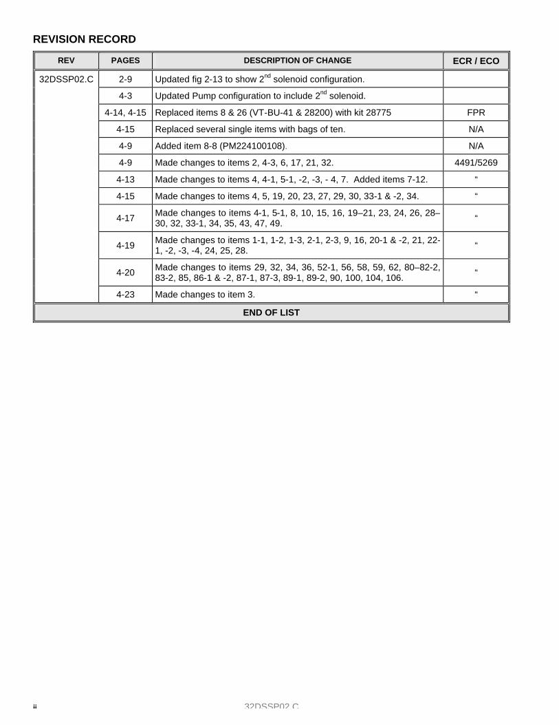
REVISION RECORD
REV PAGES DESCRIPTION OF CHANGE ECR / ECO
2-9 Updated fig 2-13 to show 2nd solenoid configuration.
4-3 Updated Pump configuration to include 2nd solenoid.
4-14, 4-15 Replaced items 8 & 26 (VT-BU-41 & 28200) with kit 28775 FPR
4-15 Replaced several single items with bags of ten. N/A
4-9 Added item 8-8 (PM224100108). N/A
4-9 Made changes to items 2, 4-3, 6, 17, 21, 32. 4491/5269
4-13 Made changes to items 4, 4-1, 5-1, -2, -3, - 4, 7. Added items 7-12. “
4-15 Made changes to items 4, 5, 19, 20, 23, 27, 29, 30, 33-1 & -2, 34. “
4-17 Made changes to items 4-1, 5-1, 8, 10, 15, 16, 19–21, 23, 24, 26, 28–30, 32, 33-1, 34, 35, 43, 47, 49. “
4-19 Made changes to items 1-1, 1-2, 1-3, 2-1, 2-3, 9, 16, 20-1 & -2, 21, 22-1, -2, -3, -4, 24, 25, 28. “
4-20 Made changes to items 29, 32, 34, 36, 52-1, 56, 58, 59, 62, 80–82-2, 83-2, 85, 86-1 & -2, 87-1, 87-3, 89-1, 89-2, 90, 100, 104, 106. “
32DSSP02.C
4-23 Made changes to item 3. “
END OF LIST

32DSSP02.C iii
S-SERIES PERSONAL TABLE OF CONTENTS
Chapter Page
I. INTRODUCTION............................................................................................................................. 1-1 RICON 5-YEAR LIMITED WARRANTY ............................................................................................................... 1-2 A. SHIPMENT INFORMATION ........................................................................................................................... 1-3 B. GENERAL SAFETY PRECAUTIONS............................................................................................................. 1-3 C. MAJOR LIFT COMPONENTS........................................................................................................................ 1-4
II. INSTALLATION.............................................................................................................................. 2-1 A. MECHANICAL INSTALLATION...................................................................................................................... 2-1
1. LIFT LOCATION........................................................................................................................................ 2-1 2. LIFT INSTALLATION GUIDELINES.......................................................................................................... 2-1 3. LIFT INSTALLATION INTO VANS ............................................................................................................ 2-2 4. LIFT INSTALLATION INTO BUSES.......................................................................................................... 2-4
B. ELECTRICAL INSTALLATION....................................................................................................................... 2-6 1. INSTALL MAIN CIRCUIT BREAKER ........................................................................................................ 2-6 2. ROUTE/CONNECT MAIN POWER CABLE.............................................................................................. 2-7 3. GROUNDING INSTRUCTIONS ................................................................................................................ 2-9 4. INSTALLATION OF UNSUPPORTED INTERLOCK DEVICES.............................................................. 2-10
C. FINAL ADJUSTMENTS................................................................................................................................ 2-15 1. LIMIT SWITCH ADJUSTMENT............................................................................................................... 2-15 2. ROLLSTOP (PLATFORM TILT) ADJUSTMENT..................................................................................... 2-16 3. SPLIT PLATFORM TIE ROD ASSEMBLY INSTALLATION AND ADJUSTMENT ................................. 2-17 4. PLATFORM PRESSURE SWITCH CHECK AND ADJUSTMENT ......................................................... 2-18 5. PLATFORM LOAD SENSOR SWITCH ADJUSTMENT ......................................................................... 2-19
D. VERIFY INSTALLATION .............................................................................................................................. 2-19 E. CUSTOMER ORIENTATION........................................................................................................................ 2-19
III. MAINTENANCE AND REPAIR....................................................................................................... 3-1 A. LUBRICATION................................................................................................................................................ 3-1 B. CLEANING...................................................................................................................................................... 3-2 C. MAINTENANCE SCHEDULE ......................................................................................................................... 3-2 D. TROUBLESHOOTING.................................................................................................................................... 3-4
1. INTERLOCK INDICATOR DIAGNOSTICS ............................................................................................... 3-4 2. LIFT TROUBLESHOOTING...................................................................................................................... 3-5
E. HYDRAULIC CIRCUIT DIAGRAM.................................................................................................................. 3-6 F. ELECTRICAL WIRING DIAGRAMS............................................................................................................... 3-7
1. DIAGRAM LEGEND .................................................................................................................................. 3-7 2. S-SERIES LIMIT SWITCH STATES ......................................................................................................... 3-8 3. WIRING DIAGRAMS ................................................................................................................................. 3-9
IV. PARTS DIAGRAMS AND LISTS .................................................................................................... 4-1 APPENDIX: LIFT SPECIFICATIONS ............................................................................................................. 4-24, 25

32DSSP02.C iv
This page intentionally left blank.

32DSSP02.C 1 - 1
I. INTRODUCTION
he RICON S-Series Personal Use Wheelchair Lift provides wheelchair access to personal vans. The patented movement provides smooth, safe entry and exit and easily lifts up to 800 pounds (364 kilograms). It is de-signed to be operated by the wheelchair occupant or a trained attendant. The lift contains a powerful electro-
hydraulic pump that includes a built-in manual backup pump. If lift loses electrical power, it can still be raised or low-ered manually.
By using lift control switches, the lift is unfolded out from vehicle (deployed). The user boards the large non-skid platform and the operator uses control switches to gently lower platform to ground. After user departs, the platform is raised and folded into vehicle (stowed). The lift is also available with a platform that splits and folds when lift is stowed, providing easy vehicle ac-cess through the lift. This manual contains installation instructions; maintenance and repair in-structions; troubleshooting guide; parts and diagram lists. It is important to user safety that lift operators be completely familiar with the operating in-structions. Once the lift is installed, it is very important that the lift be prop-erly maintained by following the Ricon recommended cleaning, lubrication, and inspection instructions. If there are questions about this manual, or additional copies are needed, please contact the Ricon Product Support Department at one of following locations:
Ricon Corporation 7900 Nelson Road Panorama City, Ca 91402........................................................................................................... (818) 267-3000 Outside (818) Area Code............................................................................................................ (800) 322-2884 World Wide Website ..........................................................................................................www.riconcorp.com
Ricon U.K. Ltd. Littlemoss Business Park, Littlemoss Road Droylsden, Manchester United Kingdom, M43 7EF .................................................................................................. (+44) 161 301 6000
T
32DSSP02.C 1-2
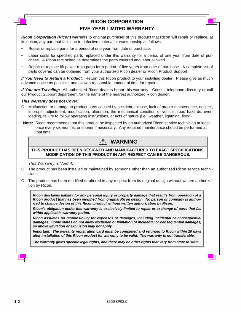
RICON CORPORATION FIVE-YEAR LIMITED WARRANTY
Ricon Corporation (Ricon) warrants to original purchaser of this product that Ricon will repair or replace, at its option, any part that fails due to defective material or workmanship as follows:
• Repair or replace parts for a period of one year from date of purchase.
• Labor costs for specified parts replaced under this warranty for a period of one year from date of pur-chase. A Ricon rate schedule determines the parts covered and labor allowed.
• Repair or replace lift power train parts for a period of five years from date of purchase. A complete list of parts covered can be obtained from your authorized Ricon dealer or Ricon Product Support.
If You Need to Return a Product: Return this Ricon product to your installing dealer. Please give as much advance notice as possible, and allow a reasonable amount of time for repairs.
If You are Traveling: All authorized Ricon dealers honor this warranty. Consult telephone directory or call our Product Support department for the name of the nearest authorized Ricon dealer.
This Warranty does not Cover: C Malfunction or damage to product parts caused by accident, misuse, lack of proper maintenance, neglect,
improper adjustment, modification, alteration, the mechanical condition of vehicle, road hazards, over-loading, failure to follow operating instructions, or acts of nature (i.e., weather, lightning, flood).
Note: Ricon recommends that this product be inspected by an authorized Ricon service technician at least once every six months, or sooner if necessary. Any required maintenance should be performed at that time.
WARNING THIS PRODUCT HAS BEEN DESIGNED AND MANUFACTURED TO EXACT SPECIFICATIONS.
MODIFICATION OF THIS PRODUCT IN ANY RESPECT CAN BE DANGEROUS.
This Warranty is Void if: C The product has been installed or maintained by someone other than an authorized Ricon service techni-
cian.
C The product has been modified or altered in any respect from its original design without written authoriza-tion by Ricon.
Ricon disclaims liability for any personal injury or property damage that results from operation of a Ricon product that has been modified from original Ricon design. No person or company is author-ized to change design of this Ricon product without written authorization by Ricon. Ricon's obligation under this warranty is exclusively limited to repair or exchange of parts that fail within applicable warranty period. Ricon assumes no responsibility for expenses or damages, including incidental or consequential damages. Some states do not allow exclusion or limitation of incidental or consequential damages, so above limitation or exclusion may not apply. Important: The warranty registration card must be completed and returned to Ricon within 20 days after installation of this Ricon product for warranty to be valid. The warranty is not transferable.
The warranty gives specific legal rights, and there may be other rights that vary from state to state.

32DSSP02.C 1 - 3
A. SHIPMENT INFORMATION
Because of the specialized nature of this product, Ricon does not sell directly to user. Instead, the product is distributed through a worldwide network of authorized Ricon service technicians, who perform actual in-stallation.
§ When the product is received, unpack it and check for freight damage. Claims for any damage should be made to freight carrier immediately.
§ Be sure installation kit contains all items listed on kit packing list. Please report any missing items immediately to Ricon Product Support. The warranty and owner registration cards must be com-pleted and returned to Ricon within 20 days for warranty to be valid.
NOTE The Sales/Service Personnel must review Warranty and this Service/Owner Manual with user to be certain that they understand safe operation of product. Instruct user to follow operating instructions without exception.
B. GENERAL SAFETY PRECAUTIONS
The following general safety precautions must be followed during installation, operation, service and main-tenance: § Under no circumstances should installation, maintenance, repair, and adjustments be attempted
without immediate presence of a person capable of rendering aid. § An injury, no matter how slight, should always be attended. Always administer first aid or seek medi-
cal attention immediately. § Protective eye shields and appropriate clothing should be worn at all times. § To avoid injury, always exercise caution when operating and be certain that hands, feet, legs, and
clothing are not in path of product movement. § Batteries contain acid that can burn. If acid comes in contact with skin, flush affected area with water
and wash with soap immediately. § Always work in a properly ventilated area. Do not smoke or use an open flame near a battery. § Do not lay anything on top of a battery. § Check under vehicle before drilling so as not to drill into frame, subframe members, wiring, hydraulic
lines, fuel lines, fuel tank, etc. § Read and thoroughly understand operating instructions before attempting to operate. § Inspect product before each use. If an unsafe condition, unusual noises or movements exist, do not
use it until problem is corrected. § Never load or stand on platform until installation is complete. Upon completion of installation, always
test load lift to 125% of its rated load capacity. § Stand clear of doors and platform and keep others clear during operation. § The product requires regular periodic maintenance. A thorough inspection is recommended at least
once every six months. The product must always be maintained at highest level of performance.
32DSSP02.C 1-4
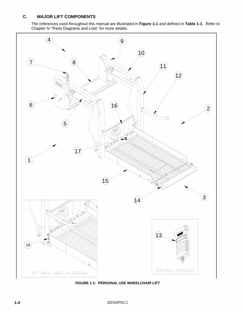
C. MAJOR LIFT COMPONENTS
The references used throughout this manual are illustrated in Figure 1-1 and defined in Table 1-1. Refer to Chapter IV “Parts Diagrams and Lists” for more details.
2
5
87
6
314
15
4
16
12
11
9
10
1
18
13
17
FIGURE 1-1: PERSONAL USE WHEELCHAIR LIFT

32DSSP02.C 1 - 5
TABLE 1-1: S-SERIES PERSONAL LIFT TERMINOLOGY
REF NAME DESCRIPTION
1 Left Lift references when installation is viewed from outside of vehi-cle.
2 Right
3 Front
4 Rear
5 Hydraulic cylinders (left and right)
Telescoping cylinders convert hydraulic pressure into platform lifting force.
6 Hydraulic power unit Contains electric motor driven pump that produces hydraulic pressure to raise and fold lift, and a pressure release valve to unfold and lower it.
7 Manual backup pump handle
Used to operate manual back up-pump when electrical power is not functional.
8 Baseplate assembly Assembly that bolts securely to vehicle floor. 9 Serial number Location of lift serial number decal.
10 Top and bottom arms (left and right)
Upper and lower parallel links connect vertical arms to base as-sembly.
11 Vertical arms (left and right) Connects platform to top and bottom arms.
12 Handrails (left and right) Provide a hand-hold for platform occupant.
13 Control pendant Hand-held device used to control lift operating functions.
14 Platform rollstop Front barrier prevents wheelchair from slowly or inadvertently rolling off of platform during lift operation.
15 Platform Area of lift where wheelchair and occupant are situated during "Up" and "Down" motions.
16 Bridgeplate (inboard rollstop)
Plate that bridges gap between platform and vehicle when plat-form is at floor height. Acts as barrier to confine wheelchair to platform during "Up" and "Down" motions.
17 Handrail switch Alternate switch that can be used by platform occupant to raise and lower lift.
18 Tie-rod assemblies (left and right)
Links on split platform models (only) that close platform sections as platform deploys.
END OF TABLE

32DSSP02.C 1-6
This page intentionally left blank.

32DSSP02.C 2 - 1
II. INSTALLATION
his chapter contains instructions for installing the RICON S-Series Personal Use Wheelchair Lift into most vans and buses, although custom installations are also possible in other types of vehicles. Due to the wide range of applications for lift, specific information for every possible application is not available. The following general
procedures will apply to most installations. Contact the Ricon Product Support Department for instruction about instal-lations not covered. To install lift, refer to following sections and perform procedures carefully and in the order that they are presented. Be certain that installation instructions are followed exactly and do not eliminate any steps or modify product.
A. MECHANICAL INSTALLATION
1. LIFT LOCATION
The installation surface must be flat and level. It is recommended that lift be installed on a ½", mini-mum, high grade plywood sub-floor. However, this additional installation height may not be acceptable in cases where overhead clearance is limited.
NOTE: Be certain to check for proper travel clearance through doorway.
a. With door(s) fully open, place/position lift in vehicle doorway as close as possible to door, with lift's baseplate assembly parallel to side of vehicle.
b. Be sure to allow a distance of 3/4", if possible, between door and the part of lift closest to it. Ad-just lift's left and right-side locations to accommodate subframe members.
c. Verify proper clearance of door frame, passenger seats, and outer edge of vehicle floor and pos-sible interference with wires, fluid lines, subframe members, etc.
2. LIFT INSTALLATION GUIDELINES The mounting of lift is a very important step. Lift performance can be greatly affected by improper mounting and/or fastening of lift. Although fastening details may vary from one vehicle to the next, some general principles always apply:
• Be certain that all mounting bolts are properly installed and tightened. Bolts used to fasten baseplate assembly to vehicle floor should be equivalent to or greater than a strength rating of SAE Grade 5 and torqued to 28 ft. lbs., dry. Always remember that the most important bolts are those at rear of lift, since these bolts retain most of load.
• Refer to Figure 2-1. Improper fastening sequence or torquing of bolts may result in a warped or buckled baseplate and, therefore, cause lift to operate unevenly.
T
FIGURE 2-1: PLATFORM MOUNTING

2-2 32DSSP02.C
• Refer to Figure 2-2. On Ford van installations, clamping bars should be used to help distribute floor loading and should only be cut if needed to clear a subframe member. A subframe member should be used to support clamping bar.
3. LIFT INSTALLATION INTO VANS a. Refer to Figure 2-3. Using four 1" x 3/8" bolts, 3/8" washers, 3/8" lock washers and 3/8" hex
nuts, assemble two bracket assembly kits. NOTE: The top bracket must overlap bottom bracket, and both slots must face outward.
b. Position and adjust height of both bracket assemblies so that top bracket is level with vehicle floor. Tighten bracket assembly bolts.
c. Ensure that lift is fully closed with handrails folded tight against vertical arms. If necessary, use manual pump.
WARNING LIFT WEIGHT IS APPROXIMATELY 350-375 LBS. TAKE EXTREME CARE WHEN POSITIONING, BRACKETS MAY TIP. DO NOT POSITION ALONE. THIS PROCEDURE SHOULD NOT BE ATTEMPTED BY ONE PERSON.
FIGURE 2-2: FORD VAN CLAMPING BAR ARRANGEMENT
FIGURE 2-3: STEPWELL BRACKET

32DSSP02.C 2 - 3
d. Refer to Figure 2-4. With door(s) fully open, position lift in vehicle doorway so that back is supported by vehicle floor and front is supported by both bracket assemblies.
e. Adjust Base Assembly: NOTE: If Ricon Power Door Operators are used, install them first. They may have some influence
on location of lift.
1) Be certain baseplate assembly is parallel with vehicle floor. The baseplate assembly may be slightly offset in door opening to provide proper clearance for passenger seats.
2) Before drilling, be certain that lift's position does not interfere with closing of vehicle door(s) as well as clear all passenger seats.
f. Mark/Drill Holes: NOTE: Before drilling any holes, be sure that no underlying
wires or tubes are in the way.
1) Refer to Figure 2-5. Mark/drill four 25/64" baseplate assembly mounting holes (1, 2, 3 and 4) through vehi-cle floor. (On Dodge and GM vans, you must drill through vehicle floor and subframe).
2) Place four 8" x 3/8" carriage bolts (4" x 3/8" bolts on Ford vans) into holes to secure position.
3) Refer to Figure 2-6. Match and align both top bracket holes 5, 6, 7 and 8 with base-plate assembly holes 5, 6, 7, and 8. Mark bracket assembly mounting holes 9, 10, 11, and 12 onto vehicle step.
4) Remove carriage bolts installed in step 2). Carefully push lift into vehicle interior.
5) Drill 1/4" holes through marked locations 9, 10, 11 and 12.
g. Fasten Bracket Assemblies/Lift: 1) Using 1-1/2" x 5/16" sheet metal screws
with 5/16" lock washers, secure lower brackets to vehicle step holes 9 through 12.
NOTE: If screw in position 12 interferes with proper door operation, do not install.
2) Reposition lift ensuring that surface beneath lift is free of obstacles. 3) Insert four 8" x 3/8" carriage bolts through mounting holes at rear of baseplate assembly,
and insert four 1-1/2" x 3/8" carriage bolts through baseplate and bracket assemblies.
FIGURE 2-4: BRACKET ASSEMBLY
FIGURE 2-5: VAN BASEPLATE
HOLES
FIGURE 2-6: TOP BRACKET HOLE LOCATIONS
2-4 32DSSP02.C
Place 3/8" washers, lock washers, and nuts under bracket assemblies, and finger tighten nuts.
NOTE: On Dodge and GM vans, place four 4" x 4" plates, 3/8" washers, lock washers and hex nuts on 8" x 3/8" carriage bolts under van and finger tighten. On Ford models, reinforce vehicle floor with clamping bars. They are to be bolted in positions 1, 2, 3 and 4 and run across width of baseplate towards center of van.
4) Before tightening carriage bolts, verify that lift is level with vehicle floor. Adjust bracket as-sembly bolts if necessary.
5) Tilting lift towards inside of van may hinder its initial unfolding. Install lift with its baseplate assembly as level as possible. Tightening carriage bolts requires special care to keep baseplate assembly from warping when secured to vehicle floor. If baseplate assembly warps, the vertical arms will not be parallel. Corrections can be made by shimming at ap-propriate locations. To help prevent warping, tighten the eight carriage bolts (six on Dodge van with sliding door) to 28 ft. lbs. in the following sequence:
DODGE WITH SWING DOORS, ALL FORD AND GM VANS: 2, 3, 6, 7, 1, 4, 5, 8
DODGE WITH SLIDING DOORS: 2, 3, 5, 8, 1, 4 NOTE: Vertical Arms must be parallel for proper operation. Adjust bolts as required. Best results
are obtained when lift is mounted on plywood. Shims, although best avoided, may be used if required.
6) Make certain that holes 13 and 14 on front of each bracket assembly are drilled through and 5/16" bolts are inserted to lock position of bracket assemblies.
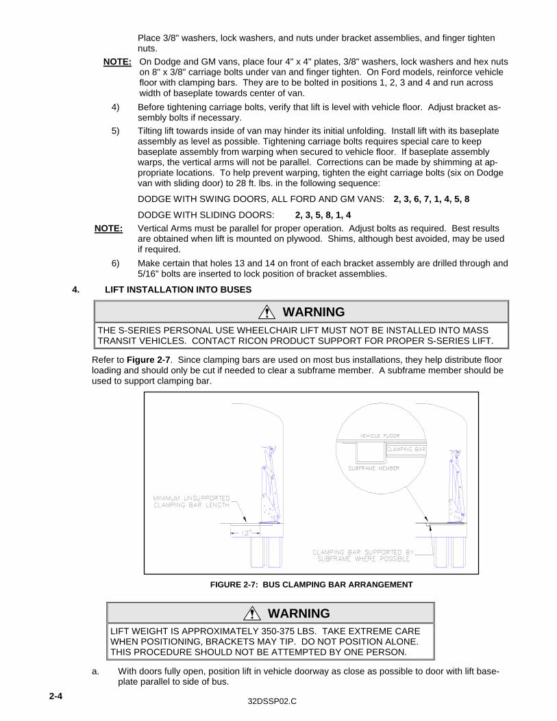
4. LIFT INSTALLATION INTO BUSES
WARNING THE S-SERIES PERSONAL USE WHEELCHAIR LIFT MUST NOT BE INSTALLED INTO MASS TRANSIT VEHICLES. CONTACT RICON PRODUCT SUPPORT FOR PROPER S-SERIES LIFT.
Refer to Figure 2-7. Since clamping bars are used on most bus installations, they help distribute floor loading and should only be cut if needed to clear a subframe member. A subframe member should be used to support clamping bar.
WARNING LIFT WEIGHT IS APPROXIMATELY 350-375 LBS. TAKE EXTREME CARE WHEN POSITIONING, BRACKETS MAY TIP. DO NOT POSITION ALONE. THIS PROCEDURE SHOULD NOT BE ATTEMPTED BY ONE PERSON.
a. With doors fully open, position lift in vehicle doorway as close as possible to door with lift base-plate parallel to side of bus.
FIGURE 2-7: BUS CLAMPING BAR ARRANGEMENT

32DSSP02.C 2 - 5
b. Refer to Figure 2-8. Mark/drill eight 25/64" baseplate as-sembly mounting holes (1 thru 8) through vehicle floor.
NOTE: Before drilling any holes, be sure that no underlying wires or tubes are in the way.
c. Fasten Lift: 1) Insert eight 4" x 3/8" carriage bolts through baseplate
and vehicle floor. 2) Install support tubes (4 ea.) to bolts underneath vehicle floor across baseplate, i.e., from 1
to 5, 2 to 6, etc., and secure lift to vehicle floor with 3/8" washers, lock washers and hex-nuts.
3) Tightening carriage bolts requires special care to keep baseplate assembly from warping when secured to vehicle floor. If baseplate assembly warps, vertical arms will not be paral-lel. Corrections can be made by shimming at appropriate locations. To help prevent warp-ing, tighten the eight carriage bolts to 28 ft. lbs. in following sequence:
2, 3, 6, 7, 1, 4, 5, 8 NOTE: Vertical Arms must be parallel for proper operation. Adjust bolts as required. Best results
are obtained when lift is mounted on plywood. Shims, although best avoided, may be used if required.
FIGURE 2-8: BUS BASEPLATE HOLES

2-6 32DSSP02.C
B. ELECTRICAL INSTALLATION
CAUTION • Do not route a wire while it is connected to the battery.
• Route wires clear of moving parts, brake lines, and the exhaust system. Secure to the vehicle.
• When routing an electrical wire through vehicle floor or walls, use a grommet to protect wires from chafing.
• Check underside of vehicle before drilling to avoid damage to fuel lines, vent lines, brake lines, or wires.
1. INSTALL MAIN CIRCUIT BREAKER
a. Disconnect battery. b. Mount main circuit breaker inside engine compartment near battery. Mount within 12 inches to
minimize amount of unprotected cable. Avoid installing near heat sources.
FIGURE 2-9: ELECTRICAL INSTALLATION DIAGRAM FIGURE [2-2]: ELECTRICAL INSTALLATION DIAGRAM

32DSSP02.C 2 - 7
2. ROUTE/CONNECT MAIN POWER CABLE
CAUTION Check under-side of vehicle before drilling to avoid damage to fuel lines, vent lines, brake lines, or wires.
NOTE: For applications where power cable is to pass through sheet metal, drill a 3/4" hole and use wire clamp provided. For applications where cable is to pass through plywood, drill a 1" hole and use black plastic grommet provided.
a. Refer to Figure 2-10. Locate and drill a hole through vehicle floor near or under pump cover so power cable may reach positive pole of solenoid, the side opposite to where solenoid is con-nected to pump motor. The hole should be drilled so that it is hidden by the pump cover.
NOTE: An 8 amp circuit breaker is provided for lift as a circuit protection device. Whatever circuit inter-face is supplied by the OEM, it should be capable of carrying 8 amps of continuous current.
b. Install ring terminals (supplied) to each end of short power cable (12" long), and one ring termi-nal to one end, and one end only, of long power cable using an appropriate crimp tool (such as Ricon P/N 26553).
c. Connect end of long 4 AWG power cable (with ring terminal) to main circuit breaker, then route power cable underneath vehicle floor and up through hole in floor.
d. Ensure that power cable is secure. Bind power cable to pump assembly harness and to pump motor using cable ties. Avoid pinch points, exhaust system, any moving parts and brake lines.
CAUTION Be sure that there is no interference with any parts that could damage power cable or other wires in any way.
IF PLATFORM WIDTH = 32”, THEN “A” = 2.25” IF PLATFORM WIDTH = 30”, THEN “A” = 1.25” “B” DIA. = 0.75” FOR SHEET METAL “B” DIA. = 1.00” FOR OTHER MATERIALS
FIGURE 2-10: POWER CABLE ACCESS HOLE

2-8 32DSSP02.C
e. Refer to Figure 2-11. Cut any excess wire from long cable, install remaining heavy ring terminal to unterminated end of long cable, and connect it to live side of solenoid. Ensure that red wire from main circuit breaker (if applicable) is connected to positive solenoid pole.
f. Refer to Figure 2-12. Connect appropriate RICON lift control interface to lift and secure control cable to lift with supplied cable clamp.
NOTE: For applications where a hand-held control pendant is used, it is essential that strain relief be in-stalled. Connect a 12" cable from battery positive terminal to main breaker terminal closest to battery.
g. Install wall portion of pendant dovetail clip in an appropriate safe location.
CAUTION Be sure that harness does not interfere with any moving parts, or binds against any parts, or is pinched in any way.
BRACKET
PENDANT INTERFACE
INSTALL DOOR OPERATORINTERFACE JUMPER IF DOOROPERATOR IS NOT USED
STRAIN RELIEF
U-BOLT
FIGURE 2-12: STRAIN RELIEF KIT
FIGURE 2-11: CABLE ROUTING
32DSSP02.C 2 - 9
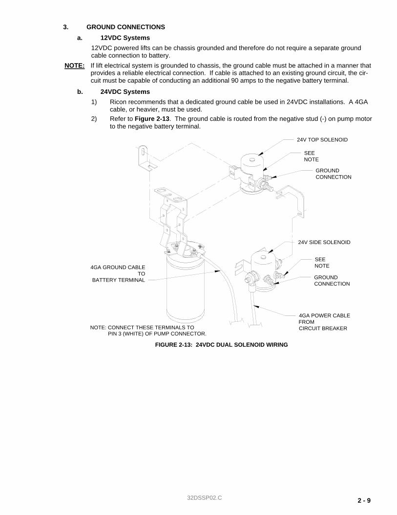
3. GROUND CONNECTIONS
a. 12VDC Systems
12VDC powered lifts can be chassis grounded and therefore do not require a separate ground cable connection to battery.
NOTE: If lift electrical system is grounded to chassis, the ground cable must be attached in a manner that provides a reliable electrical connection. If cable is attached to an existing ground circuit, the cir-cuit must be capable of conducting an additional 90 amps to the negative battery terminal.
b. 24VDC Systems
1) Ricon recommends that a dedicated ground cable be used in 24VDC installations. A 4GA cable, or heavier, must be used.
2) Refer to Figure 2-13. The ground cable is routed from the negative stud (-) on pump motor to the negative battery terminal.
24V TOP SOLENOID
4GA POWER CABLEFROMCIRCUIT BREAKER
24V SIDE SOLENOID
4GA GROUND CABLETO
BATTERY TERMINAL GROUNDCONNECTION
GROUNDCONNECTION
SEENOTE
SEENOTE
NOTE: CONNECT THESE TERMINALS TOPIN 3 (WHITE) OF PUMP CONNECTOR.
FIGURE 2-13: 24VDC DUAL SOLENOID WIRING

2-10 32DSSP02.C
4. INSTALLATION OF UNSUPPORTED INTERLOCK DEVICES
An interlock device may be installed that is designed to prevent operation of lift or vehicle when it is not safe to do so. The interlock supplied by the installing Ricon dealer is not a Ricon product.
Some interlock devices lock vehicle transmission in PARK when lift is deployed, or do not allow lift to be deployed unless vehicle transmission is in PARK and emergency brake is set. Other devices will stall vehicle's engine if lift is deployed and emergency brake is released or transmission is shifted from PARK. There may be other types of interlock devices that disable lift or vehicle and prevent unsafe lift operating conditions.
Because these devices are non-Ricon products, Ricon is not aware of all that are available. For this reason it is very important that interlock device be properly installed, such that it does not interfere with safe operation of lift or create an electrical or fire hazard. The installer should always be certain that none of the original equipment electrical circuit breakers, fuses or solenoids are bypassed, removed or altered. Be sure that no wires are left frayed or hanging loose after installation of interlock device. If you have any questions about proper installation of these interlock devices, please contact our Product Support Department immediately. DO NOT OPERATE LIFT UNLESS YOU ARE CERTAIN THAT INTEGRITY OF LIFT'S ELECTRICAL CIRCUITS, AS DESIGNED, HAS BEEN MAINTAINED.
CAUTION Wiring attached directly to a battery's positive terminal is not protected against short circuits. Wiring attached directly to a battery must be kept as short as possible (12" or less) and must be routed so that there is no risk of pinching. Wires for interlock circuit should be routed from an appropriately protected power source such as a dedicated accessory on an existing fuse panel.
Ricon recommends use of one of the three following installation methods:
a. INTERLOCK METHOD #1 (Signal interrupt, feed from lift)
Refer to Figure 2-14. This method interrupts power to the lift hand control pendant. It does not require additional circuit protection, but does require a modification to lift harness.
1) Disconnect battery. 2) Remove piggyback spade connector wire from OUTPUT side of 8 amp circuit breaker (refer
to decal on circuit breaker). NOTE: The OUTPUT side of breaker must be used to avoid possibility of an electrical short.
3) Connect female spade connector of interlock circuit provided by installer to OUTPUT side of 8 amp breaker using 16 AWG or larger wire.
NOTE: All connectors provided on interlock circuit must be a fully insulated type.
4) Cut piggyback connector from light assembly and female spade connector from signal power wire. Strip both wires about ½" being careful not to nick conductor. Crimp both wires in a single 1/4" fully insulated female spade connector designed for use on 14-16 AWG wire.
5) Connect male spade connector of interlock circuit to female spade connector added to har-ness in above step.
6) Dress wires in such a way as to not allow rubbing or chafing of insulation, and so there is no strain at any terminals or body of light.
b. INTERLOCK METHOD #2 (Signal interrupt, feed from vehicle)
Refer to Figure 2-15. This method interrupts power between lift's 8 amp breaker and vehicle's battery. It requires circuit protection to be provided by installer.
1) Disconnect battery. 2) The cable leading to applicable circuit protection from battery must be at least 16 AWG or
larger, and must not exceed 12" in length. 3) Connect INPUT side of interlock circuit to OUTPUT side of circuit protector using 16 AWG
or larger wire.

32DSSP02.C 2 - 11
4) If an optional 30 amp circuit breaker has been installed next to 8 amp breaker, completely remove the 18 AWG wire connecting INPUT sides of 30 amp and 8 amp circuit breakers. To do this, the spade connector must be removed from 8 amp INPUT and 18 AWG wire must be cut as close as possible to 30 amp INPUT connector, since it is crimped to that connector along with a 10 AWG wire.
5) Connect OUTPUT side of interlock circuit to INPUT side of lift's 8 amp circuit breaker using 16 AWG or larger wire.
6) Re-connect battery.
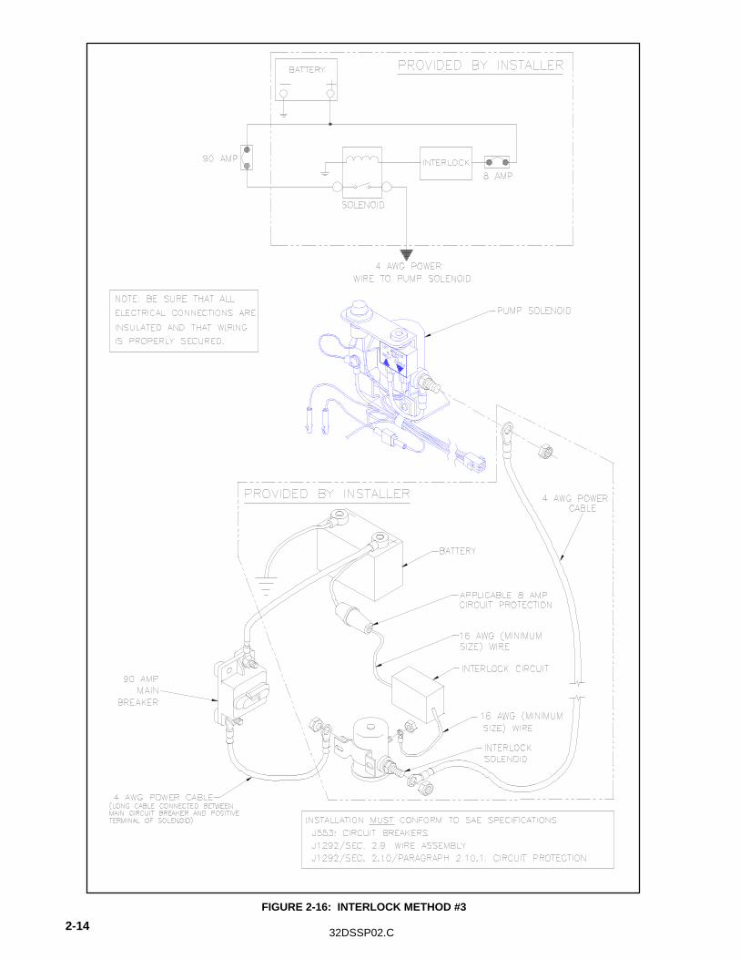
c. INTERLOCK METHOD #3 (Power interrupt)
Refer to Figure 2-16. This method interrupts power between interlock's solenoid and battery. This cuts all power to lift. It requires circuit protection to be supplied by installer.
1) Disconnect battery. 2) Disconnect 4 AWG power cable from main breaker at pump solenoid. 3) Connect cable to one of terminal posts of interlock solenoid. 4) Connect other terminal post of interlock solenoid to empty terminal post of pump solenoid
using 4 AWG wire. 5) Connect circuit protector provided by installer (should be 8 amp, maximum) to main power
cable coming from battery (which should be disconnected at this time) using wire at least 16 AWG or larger, not to exceed 12" in length. Be sure that wiring cannot pinch or chafe.
6) Connect OUTPUT side of circuit protector to INPUT side of interlock circuit provided by in-staller using 16 AWG or larger wire.
7) Connect OUTPUT side of interlock circuit to coil terminal of solenoid using 16 AWG or lar-ger wire.
8) Be sure that interlock solenoid is properly grounded. If a separate grounding post is pro-vided, connect a 16 AWG wire from ground post to a suitable chassis ground. If coil is grounded through body of solenoid, be sure that solenoid is mounted to a suitable chassis ground.
9) Reconnect battery.

2-12 32DSSP02.C
FIGURE 2-14: INTERLOCK METHOD #1

32DSSP02.C 2 - 13 FIGURE 2-15: INTERLOCK METHOD #2
2-14 32DSSP02.C FIGURE 2-16: INTERLOCK METHOD #3
32DSSP02.C 2 - 15
C. FINAL ADJUSTMENTS
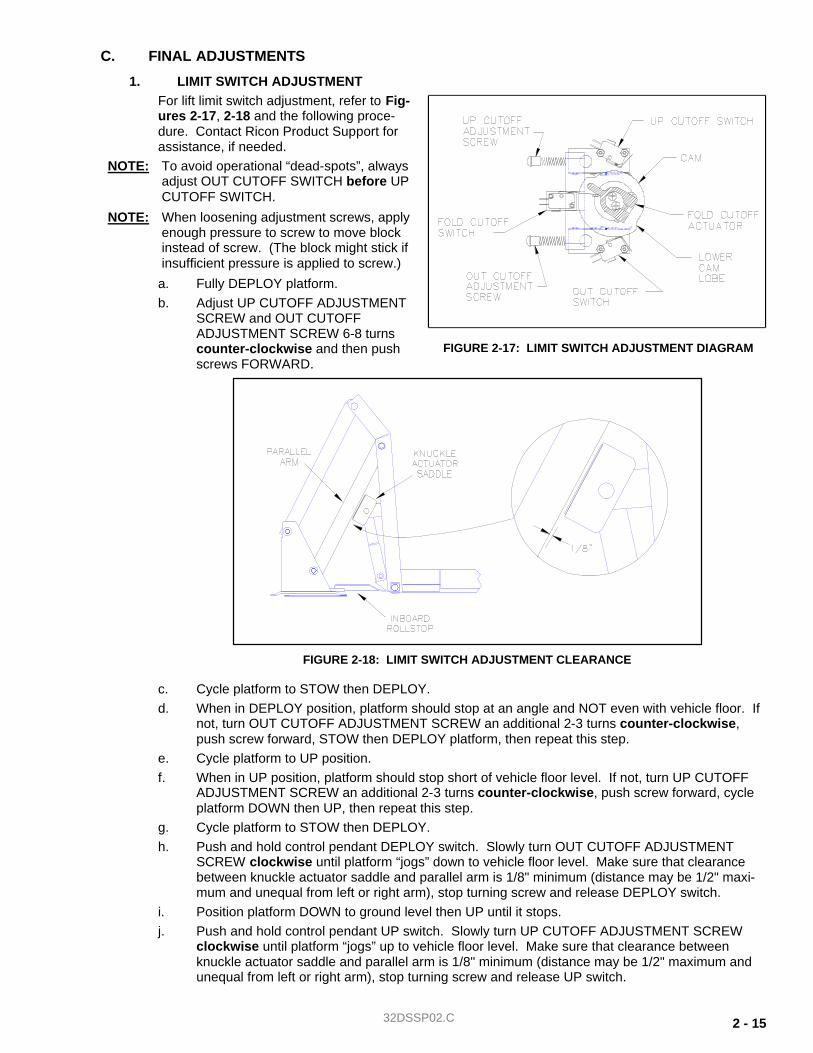
1. LIMIT SWITCH ADJUSTMENT For lift limit switch adjustment, refer to Fig-ures 2-17, 2-18 and the following proce-dure. Contact Ricon Product Support for assistance, if needed.
NOTE: To avoid operational “dead-spots”, always adjust OUT CUTOFF SWITCH before UP CUTOFF SWITCH.
NOTE: When loosening adjustment screws, apply enough pressure to screw to move block instead of screw. (The block might stick if insufficient pressure is applied to screw.)
a. Fully DEPLOY platform. b. Adjust UP CUTOFF ADJUSTMENT
SCREW and OUT CUTOFF ADJUSTMENT SCREW 6-8 turns counter-clockwise and then push screws FORWARD.
c. Cycle platform to STOW then DEPLOY. d. When in DEPLOY position, platform should stop at an angle and NOT even with vehicle floor. If
not, turn OUT CUTOFF ADJUSTMENT SCREW an additional 2-3 turns counter-clockwise, push screw forward, STOW then DEPLOY platform, then repeat this step.
e. Cycle platform to UP position. f. When in UP position, platform should stop short of vehicle floor level. If not, turn UP CUTOFF
ADJUSTMENT SCREW an additional 2-3 turns counter-clockwise, push screw forward, cycle platform DOWN then UP, then repeat this step.
g. Cycle platform to STOW then DEPLOY. h. Push and hold control pendant DEPLOY switch. Slowly turn OUT CUTOFF ADJUSTMENT
SCREW clockwise until platform “jogs” down to vehicle floor level. Make sure that clearance between knuckle actuator saddle and parallel arm is 1/8" minimum (distance may be 1/2" maxi-mum and unequal from left or right arm), stop turning screw and release DEPLOY switch.
i. Position platform DOWN to ground level then UP until it stops. j. Push and hold control pendant UP switch. Slowly turn UP CUTOFF ADJUSTMENT SCREW
clockwise until platform “jogs” up to vehicle floor level. Make sure that clearance between knuckle actuator saddle and parallel arm is 1/8" minimum (distance may be 1/2" maximum and unequal from left or right arm), stop turning screw and release UP switch.
FIGURE 2-18: LIMIT SWITCH ADJUSTMENT CLEARANCE
FIGURE 2-17: LIMIT SWITCH ADJUSTMENT DIAGRAM

2-16 32DSSP02.C
NOTE: If lift does not operate after 1-2 full turns of adjustment screw, cycle platform UP and DOWN (The UP CUTOFF SWITCH is less sensitive than OUT CUTOFF SWITCH.)
k. Cycle platform through all functions (DEPLOY, DOWN, UP and STOW) to verify correct adjust-ment. Refer to Table 2-1 if necessary.
TABLE 2-1: LIMIT SWITCH ADJUSTMENT CHART
COMPONENT SYMPTOM CORRECTIVE ACTION ADJUSTMENT PROCEDURE
Fold cutoff actuator
Lift does not fold tightly.
Rotate collar counter-clockwise.
With lift fully folded (handrails should be folded tight against vertical arms), rotate actuator so that fold cutoff leg barely trips fold cutoff switch.
Pump runs continuously.
Rotate collar clockwise.
Test lift. Pump should cutoff when lift is folded tight.
Up cutoff adjustment screw
Lift stops low.
Adjust screw clockwise.
Adjust up cutoff switch so that lift stops just before first knuckle actuator saddle or roller touches underside of lower parallel arm. (Saddle or roller should be about 1/8" from lower parallel arm.)
Lift stops high.
Adjust screw counter-clockwise.
Out cutoff adjustment screw
Lift stops low.
Adjust screw counter-clockwise.
Adjust lower limit switch so that lift stops just below "Up" cutoff described in above step. This will give the necessary overlap to avoid "dead" spots.
Lift stops high.
Adjust screw clockwise.
END OF TABLE
2. ROLLSTOP (PLATFORM TILT) ADJUSTMENT
Correct platform tilt adjustment is crucial for proper platform rollstop operation, but cannot be adjusted at factory. Factors such as vehicle floor height, lift tilt angle and stiffness of vehicle springs will vary in-stallation geometry. a. Deploy and lower lift platform to a position halfway between vehicle floor level and ground level. b. Refer to Figure 2-19. Adjust left and right
platform set screws until platform is level at zero (0) degrees. Turn set screws clockwise to angle front-end of platform upward, or counter-clockwise to angle downward.
♦ At ground level, the distance between heel of platform and ground should be 3/4" to 1". This distance should be measured at initial point of rollstop's full deployment.
NOTE: Adjust set screws on both sides of platform simultaneously and evenly to ensure proper leveling of platform.
c. Repeat steps a and b as required to achieve proper rollstop operation.
FIGURE 2-19: PLATFORM SET SCREWS

32DSSP02.C 2 - 17
3. SPLIT PLATFORM TIE ROD ASSEMBLY INSTALLATION AND ADJUSTMENT
CAUTION
Stowing platform without tie rod assemblies installed will cause severe damage to platform. Do not attempt to stow platform before tie rod assemblies are installed and adjusted.
All S-Series split platform model lifts are equipped with tie rod assemblies, which open the platform panels as lift is stowed. Correct adjustment of these tie rods is needed to prevent tie rod breakage. a. Lower platform below vehicle floor level. b. Refer to Figure 2-20. Assemble rod end attachment brackets to left and right tie rod assemblies
at right-hand ball joint.
NOTE: Correct positioning of ball joint on inside of rod end attachment bracket.
c. Assemble rod end attachment brackets to corresponding platform panels using screws and Loc-TITE blue.
CAUTION
Do not lengthen tie rod stud to point where panel will lift off its tab support (at center of lift fork).
d. Adjust left tie rod assembly. Adjust tie rod stud until nearly all of link free-play is out by lengthen-ing rod.
NOTE: The left platform panel should be adjusted first so that it is slightly higher than right platform panel. This will ensure proper insertion of left panel joining pin through hole in right platform panel.
e. Raise platform to point just before panel joining and adjust right tie rod assembly for proper join-ing.
f. Lower platform below vehicle floor level.
NOTE: There must be no tension or compression on tie rod assemblies when platform is at, or below, the vehicle floor level.
g. Stow and deploy lift several times to ensure both platform panels join correctly. Readjust, if nec-essary, and then tighten lock nuts against ball joints to secure adjustment.
FIGURE 2-20: ROD END INSTALLATION

2-18 32DSSP02.C
4. PLATFORM PRESSURE SWITCH CHECK AND ADJUSTMENT (serial no.’s 104,000 to present) Correct adjustment of this pressure switch is required to prevent platform from folding into vehicle when there is a load of 50 lbs, or more, on the platform. a. Refer to Figure 2-21. Deploy and lower platform to ground. Place a 50 lb. load in center of plat-
form and then raise platform to floor level. Press and hold STOW switch.
b. Pressure switch is correctly set if pump motor shuts off, preventing further movement of platform. There should not be excessive on/off clicking of pump motor that would indicate switch is mar-ginally set. Proceed to next step if pump motor does not shut off.
c. Refer to Figure 2-22. Remove the 1/4-20 x 1.00" set screw (with hex recess) from end of pres-sure switch to gain access to adjustment screw. Save screw for reinstallation.
d. Insert a 1/8" hex wrench into pressure switch and engage adjustment screw inside. Turn screw 1/8 turn clockwise, and then repeat 50 lb. load check described above. Repeat adjustment, as necessary, to achieve correct setting.
e. Reinstall set screw and tighten against adjustment screw.
FIGURE 2-21: PRESSURE SWITCH TEST AT FLOOR LEVEL
FIGURE 2-22: HYDRAULIC PUMP WITH PRESSURE SWITCH

32DSSP02.C 2 - 19
5. PLATFORM LOAD SENSOR SWITCH ADJUSTMENT (serial no.’s 0 - 103,999)
This procedure provides for setting platform load sensor switch to prevent lift from folding past vehicle floor level when a load of 50-lbs is on center of platform.
a. Refer to Figure 2-23. Place your left hand around knuckle ver-tical link assembly as shown; link is located on left side of lift.
b. Loosen two hex-bolts shown. c. Exert a light downward pressure through your left-hand fingers
onto load sensor bar, and retighten hex-bolts. d. Refer to Figure 2-21. To verify proper load sensor switch op-
eration, deploy and lower platform to ground. Place a 50 lb. load in center of platform and then raise platform to floor level. Press and hold STOW switch.
NOTE: If pump motor does not stall or clicks off/on excessively, loosen two hex bolts, push down further on load sensor bar, and re-tighten bolts.
e. Repeat above two steps as necessary until pump motor stalls (i.e., load sensor switch is activated, preventing lift platform from folding past vehicle floor level).
D. VERIFY INSTALLATION
§ Be certain that no vehicle components interfere with operation of lift. § The lift is designed to carry the weight of a wheelchair and its passenger. The vehicle structure must
be capable of supporting all loads produced during lift operation, as well as those forces caused by motion of vehicle when it is driven.
CAUTION • Do not operate lift when test weight is on platform. This load test is designed to test the lift
mounting method, not the lift capacity. Remove test weight immediately after test.
• Vehicle suspension will compress and vehicle will lean when test weight is placed on platform. If weighted platform contacts ground, remove weight, raise platform, and retest.
§ The lift must be test loaded to 125% of its rated 800 pound load capacity to verify integrity installation. Position lift platform 2" - 6" above the ground, place 1000 pounds in center of platform, and inspect lift mounting points. REMOVE TEST WEIGHT.
§ Run lift through several complete cycles while checking for proper operation.
E. CUSTOMER ORIENTATION
IMPORTANT - Customer Orientation -
Ricon Sales/Service Personnel should review the warranty card and Operator manual with the cus-tomer to be certain they understand safe operation of the lift. The customer should be instructed to follow the operating instructions without exception.
§ Refer to Figure 2-24 on next page and ensure that all decals are properly located and affixed as shown.
NOTE
The installing dealer must affix Operating Instructions decal to vehicle in a location clearly visible to lift operator.
FIGURE 2-23: LOAD SENSOR ADJUSTMENT

2-20 32DSSP02.C
FIGURE 2-24: DECAL LOCATIONS AND PART NUMBERS

32DSSP02.C 3 - 1
III. MAINTENANCE AND REPAIR
egular maintenance of the RICON S-Series Personal Use Wheelchair Lift will optimize its performance and re-duce the need for repairs. This chapter contains lubrication and cleaning instructions, a maintenance sched-ule, troubleshooting section, and maintenance diagrams.
CAUTION This Ricon product is highly specialized. Maintenance and repairs must be performed only by an authorized Ricon dealer using only Ricon replacement parts. Modifying or failing to properly maintain this product will void warranty and may result in unsafe operating conditions.
A. LUBRICATION
CAUTION Do not lubricate motor or other electrical components. lubrication of electrical components may create unintentional short circuits.
Lubrication should be performed at least every six months, or sooner depending on usage. Refer to Figure 3-1 and following Maintenance Schedule. Lubricate lift at points specified. If lift is equipped with split plat-form, make sure that platform tie-rods are clear, clean and lubricated.
R
FIGURE 3-1: LIFT LUBRICATION POINTS

32DSSP02.C 3-2
B. CLEANING Regular cleaning with mild soap (i.e. dish soap, car wash liquid) and drying thoroughly will protect lift painted surfaces. Cleaning is especially important in areas where roads are salted in winter. Make sure that lift pivot points remain clear and clean prior to lubrication.
C. MAINTENANCE SCHEDULE Under normal operating conditions, maintenance inspections are required at least every six months (1750 cycles) and a thorough inspection should be performed at service intervals referenced in Table 3-1. Service should be increased under conditions of heavier use (more than 10 cycles per day).
TABLE 3-1: MAINTENANCE SCHEDULE
SERVICE POINT ACTION TO PERFORM
DAILY SAFETY CHECK
Overall Condition Listen for any abnormal noises as lift operates (i.e., grinding or binding noises).
Control Pendant Check that control pendant is not damaged and cable connectors are tight.
TWO-WEEK SAFETY CHECK
Overall Condition 1. Listen for any abnormal noises as lift operates (i.e., grinding or bind-
ing noises). 2. Inspect underside of vehicle to be certain nothing is out of the ordi-
nary.
Control Pendant Check that control pendant is not damaged and cable connectors are tight.
Electrical Wiring Inspect electrical wiring for frayed wires, chaffed wires, loose connec-tors, etc.
Vehicle Interlock Place vehicle in NON-INTERLOCK mode and attempt to operate lift.
Decals Be certain that all lift decals are affixed properly, clearly visible and legi-ble. Replace if necessary.
Handrails Be certain that all handrail fasteners are properly tightened.
Lift Mountings and Support Points
1. Be certain that all lift mounting and support points are in proper or-der and free from damage.
2. Be certain that all mounting bolts are sufficiently tight.
Main Lifting Pivots Be certain all traveling frame pins are installed properly, free from dam-age and locked in position.
Platform and Platform Attachment Points
Be certain platform operates properly during lift functions without ob-struction(s).
Inner Rollstop 1. Be certain that inner rollstop operates properly during lift functions
without obstruction(s). 2. Be certain that inner rollstop deploys fully as platform stops at
proper vehicle floor level.
Platform Rollstop Be certain that rollstop operates properly without obstruction(s) when it contacts ground.
Hydraulic Power Unit
CAUTION DO NOT ADD FLUID UNTIL PLATFORM IS LOWERED TO GROUND LEVEL. ADDING FLUID WHILE LIFT IS STOWED WILL CAUSE TANK TO OVERFLOW WHEN PLATFORM IS LOWERED.
1. Check for visible hydraulic fluid leakage. 2. Be certain backup pump manual release valve is lightly-snug.
SIX-MONTH SAFETY CHECK (or @ 1750 cycles of operation)
Handrails Be certain that all handrail fasteners are properly tightened.
32DSSP02.C 3 - 3
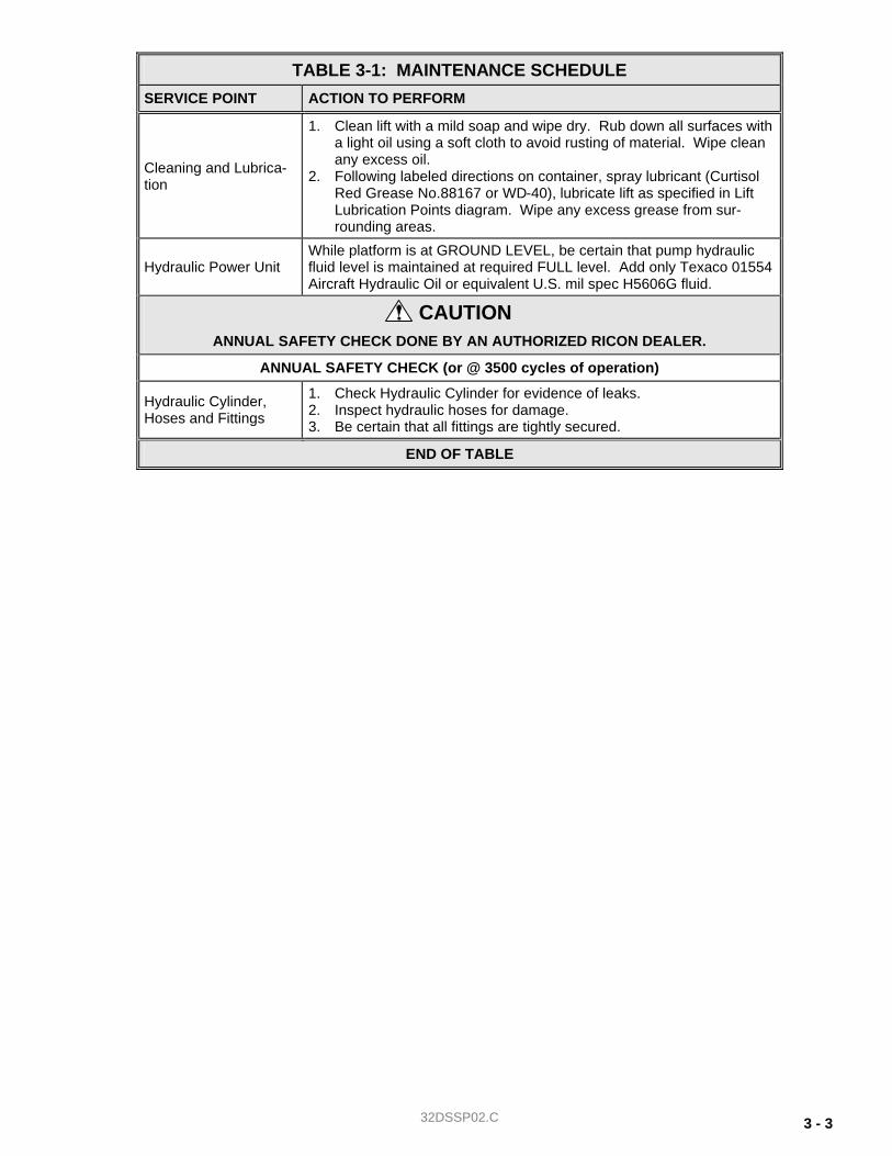
TABLE 3-1: MAINTENANCE SCHEDULE
SERVICE POINT ACTION TO PERFORM
Cleaning and Lubrica-tion
1. Clean lift with a mild soap and wipe dry. Rub down all surfaces with a light oil using a soft cloth to avoid rusting of material. Wipe clean any excess oil.
2. Following labeled directions on container, spray lubricant (Curtisol Red Grease No.88167 or WD-40), lubricate lift as specified in Lift Lubrication Points diagram. Wipe any excess grease from sur-rounding areas.
Hydraulic Power Unit While platform is at GROUND LEVEL, be certain that pump hydraulic fluid level is maintained at required FULL level. Add only Texaco 01554 Aircraft Hydraulic Oil or equivalent U.S. mil spec H5606G fluid.
CAUTION ANNUAL SAFETY CHECK DONE BY AN AUTHORIZED RICON DEALER.
ANNUAL SAFETY CHECK (or @ 3500 cycles of operation)
Hydraulic Cylinder, Hoses and Fittings
1. Check Hydraulic Cylinder for evidence of leaks. 2. Inspect hydraulic hoses for damage. 3. Be certain that all fittings are tightly secured.
END OF TABLE

32DSSP02.C 3-4
D. TROUBLESHOOTING
The troubleshooting guides are designed to provide logical starting points to locate general problems that could occur with lift. However, not all possible problems or combinations of problems are listed. For trou-bleshooting lift, refer to Tables 3-2 and 3-3. The guides do not incorporate routine safety precautions or preliminary procedures and assume that vehicle battery is fully charged and batter terminals/connectors are clean and tight.
WARNING THE TROUBLESHOOTING GUIDES DO NOT INCORPORATE ROUTINE SAFETY PRECAUSTIONS OR PRELIMINARY PROCEDURES. DURING THE RICON WARRANTY PERIOS ONLY A TRAINED, AUTHORIZED RICON DEALER MAY PERFORM TROUBLESHOOTING. AFTER WARRANTY PERIOD, IT IS RECOMMENDEDHTAT TROUBLESHOOTING BE PERFORMED BY AN AUTHORIZED RICON DEALER.
1. INTERLOCK INDICATOR DIAGNOSTICS The purpose of a vehicle interlock system is to prevent operation of lift if an unsafe condition is present. When vehicle interlock systems are interfaced with lift circuitry, the interlock indicator shows whether or not interlock is operating properly. The light is interfaced with electrical system so that no matter which interlock system/method is used, the light will be ON when interlock allows electrical power to lift and OFF when interlock has disabled power to lift. When there is no interlock system installed, the light stays illuminated at all times. A light-assembly is installed in the position where door operator circuit breaker would normally be mounted on all lift assemblies without optional door operator. The light indicates power is supplied to signal portion of electrical system, and will aid in diagnosing electrical problems.
TABLE 3-2: INTERLOCK INDICATOR TROUBLESHOOTING GUIDE
SYMPTOM POSSIBLE CAUSE
Light is not lit, lift does not operate. Control system circuit breaker is tripped.
Interlock system is not allowing power to lift due to an unsafe condition or a faulty interlock.
Light is not lit, lift operates. Light needs to be replaced.
Light is lit, lift works in an unsafe condition. Interlock is not functioning.
Light is lit, lift does not operate. There is a problem with electrical system, either with power or signal side. Both will have to be checked, but start with power side since it is less complicated.
END OF TABLE

32DSSP02.C 3 - 5
2. LIFT TROUBLESHOOTING
TABLE 3-3: LIFT OPERATION TROUBLESHOOTING
SYMPTOM POSSIBLE CAUSE REMEDY
HYDRAULIC FLUID LEAKS Loose hydraulic fitting. Make sure fitting is PROPERLY tightened.
Hydraulic component defective.
Discontinue use of lift until repairs are made by an authorized Ricon dealer.
ROLLSTOP DOES NOT OPEN
Obstruction of rollstop release latch. Raise lift and remove obstruction.
LIFT FUNCTIONS
Abnormal Operation.
Obstruction in lifting frame.
Remove obstruction and check for any damage
Backup pump manual release valve OPEN.
Turn manual release valve CLOCKWISE until lightly-snug.
Hydraulic fluid may be low.
While platform is at GROUND LEVEL, be certain that pump hydraulic fluid level is maintained at required FULL level. Add only Texaco 01554 Aircraft Hydraulic Oil or equivalent U.S. mil spec H5606G fluid.
Air may be trapped in hydraulic system.
Purge hydraulic system by operating lift through its maximum range of travel for at least four complete cycles. (For vehicles that do not use full travel of lift, the maxi-mum range of travel is accomplished by raising vehicle on a service hoist or ramp.)
No Opera-tion.
Control System Circuit Breaker tripped. Reset circuit breaker.
Backup pump manual release valve OPEN.
Turn manual release valve CLOCKWISE until lightly-snug.
Hydraulic hose or fitting leak.
Contact an authorized Ricon dealer for re-pair.
Hydraulic fluid may be low.
While platform is at GROUND LEVEL, be certain that pump hydraulic fluid level is maintained at required FULL level. Add only Texaco 01554 Aircraft Hydraulic Oil or equivalent U.S. mil spec H5606G fluid.
Air may be trapped in hydraulic system.
Purge hydraulic system by operating lift through its maximum range of travel for at least four complete cycles. (For vehicles that do not use full travel of lift, the maxi-mum range of travel is accomplished by raising vehicle on a service hoist or ramp.)
END OF TABLE

32DSSP02.C 3-6
E. HYDRAULIC CIRCUIT DIAGRAM
FIGURE 3-2: S-SERIES HYDRAULIC CIRCUIT

32DSSP02.C 3 - 7
F. ELECTRICAL WIRING DIAGRAMS
1. DIAGRAM LEGENDS
a. Wire Color Codes
TABLE 3-4: WIRE COLOR CODES
LETTER COLOR LETTER COLOR
BK Black R Red
BL Blue VI Violet
BR Brown GY Gray
GN Green W White
O Orange Y Yellow
END OF TABLE
b. Electrical Connector Description Refer to Figure 3-3. The standard electrical connectors used by Ricon are Molex .062” Series. These connectors have ter-minal numbers stamped onto the rear, use these numbers to identify wires.
c. Diagram Labels
FIGURE 3-3: MOLEX CONNECTORS

32DSSP02.C 3-8
d. Electrical Symbols
Figure 3-4 defines symbols used in the electrical wiring diagrams.
2. S-SERIES LIMIT SWITCH STATES Refer to Figure 3-5. The actuation diagram shows the state of all limit switches as the platform travels from stowed, to vehicle floor level, and then to ground level. The solid line segments represent current flow through the normally CLOSED switch contacts, and the open line segments represent current flow through the normally OPEN switch contacts. The heavy dashed lines show switch states when platform is beyond normal travel boundaries. This is useful in showing the operation of switches that change states at stowed or ground level positions. For proper operation of lift, the switch actuations must overlap as shown.
FIGURE 3-4: DIAGRAM SYMBOLS
FIGURE 3-5: LIMIT SWITCH ACTUATION

32DSSP02.C 3 - 9
3. WIRING DIAGRAMS
FIGURE 3-6: WIRING DIAGRAM FOR LIFT W/DOOR OPERATOR

32DSSP02.C 3-10
FIGURE 3-7: WIRING DIAGRAM FOR LIFT W/O DOOR OPERATOR

32DSSP02.C 4 - 1
IV. PARTS DIAGRAMS AND LISTS his chapter contains parts diagrams and parts lists for the RICON S-Series Personal Use Wheelchair Lift. An exploded view of each major lift assembly shows individual components and assemblies referenced by num-bers. On each associated list is the reference number, a part description, the quantity used, and the Ricon part
number. For part numbers of lift decals, refer to the “Decal Locations and Part Numbers” figure in Chapter II of this manual.
LIFT MODEL AND KIT NUMBERS
PRODUCT NUMBERS 1100-P00100100 (first model in number sequence)
DOCUMENTATION KIT NUMBER 01071
PRODUCTION DECAL SET NUMBERS XXXXLPXXXXXXXX
SPARE DECAL KIT NUMBER 26014
PARTS DIAGRAM ................................................................................................................................................... PAGE
FIGURE 4-1: MONARCH HYDRAULIC POWER UNIT #1 ........................................................................................ 4-2 FIGURE 4-2: MONARCH HYDRAULIC POWER UNIT #2 ........................................................................................ 4-6 FIGURE 4-3: S-SERIES HYDRAULIC SYSTEM ....................................................................................................... 4-8 FIGURE 4-4: S-SERIES ELECTRICAL SYSTEM.................................................................................................... 4-10 FIGURE 4-5: S-SERIES PENDANT......................................................................................................................... 4-12 FIGURE 4-6: S-SERIES SOLID PLATFORM .......................................................................................................... 4-14 FIGURE 4-7: S-SERIES SPLIT PLATFORM ........................................................................................................... 4-16 FIGURE 4-8: S-SERIES TRAVELING FRAME........................................................................................................ 4-18 FIGURE 4-9: S-1200 HANDRAIL ............................................................................................................................. 4-22
LIFT SPECIFICATIONS ....................................................................................................................................... 4-24, 25
T

32DSSP02.C 4 - 2
FIGURE 4-1: MONARCH HYDRAULIC POWER UNIT #1
DWG. SSX00001
DATE: 05/05/04
REV K
36
19
23
44
41
24
2
3
8
1
6
7
9
10
11
13
12
14
1622
1019
20
21
18
26
27
38
28
40
30
49
39
3233
34
35
37
42
43
15
17
25
45
4
5
29
31

32DSSP02.C 4 - 3
FIGURE 4-1: MONARCH HYDRAULIC POWER UNIT #1 S-SERIES (ALL MODELS) WHEELCHAIR LIFT
SERIAL NO's. 31000 – 31999; SERIAL NO's. 35000 - PRESENT
REF. DESCRIPTION QTY. PART NO. 1 SCREW,10-24 X ½ PAN HEAD, SELF THREAD 3 28111T 2 SOLENOID, SPST, 12V 1 19066 3 SOLENOID, SPST, 24V 1 26449 4 HARNESS, PUMP, w/DOOR INTERLOCK, (S/N’s 32000-95999) 1 V2-ES-100 HARNESS, PUMP, w/DOOR INTERLOCK, (SN 96000 - present) 1 10069 5 HARNESS, PUMP, w/o DOOR INTERLOCK, (S/N’s 32000-95999) 1 V2-ES-150 HARNESS, PUMP, w/o DOOR INTERLOCK, (SN 96000 - present) 1 10335 6 NUT, NYLON INSERT, 10-24, BAG OF 10 3 13382 7 SOLENOID, DPST, 12V 1 20670 SOLENOID, DPST, 24V 1 26450 8 BUS BAR, MOTOR, SP SOLENOID, (S/N’s 52456-95999) 1 V2-ES-034 BUS BAR (SN 96000 - present) 1 10807 9 BUS BAR, MOTOR, DP SOLENOID, (S/N’s 32000-95999) 1 UV-ES-040 10 BUS BAR (SN 96000 - present) 1 13087 11-1 MOTOR ASSY, 12V, 3", MONARCH PUMP 1 V2-SH-115 11-2 MOTOR ASSY, 24V, 3", MONARCH PUMP 1 V2-ES-116 11-3 MOTOR ASSY, 12V ISKRA (SN 96000 - present) 1 14332 MOTOR ASSY, w/BRACKET, 12V ISKRA 1 14345 11-4 MOTOR ASSY, 24V ISKRA (SN 96000 - present) 1 14333 MOTOR ASSY, w/BRACKET, 24V ISKRA 1 14346 12 FITTING ASSY, ELBOW, #4 STD THD X #4 JIC, w/HDWR 1 18235 13 DECELERATION VALVE ASSY 1 V2-SH-279 14 PLUG, 3/4-16 CAVITY, w/O-RING 2 V2-SH-001 15 SWITCH, HYDRAULIC PRESSURE 1 15207 16 PLUG w/O-RING 1 V2-SH-182 17 LIGHT ASSY, INDICATOR, 12V 1 19067 18-1 SPOOL VALVE ASSY, 12V, ADA APPLICATIONS 1 01176 18-2 SPOOL VALVE ASSY, 24V, ADA APPLICATIONS 1 01177 19 RESERVOIR, RICON POWER UNIT, PLASTIC 1 V2-SH-108 20 PLUG, BREATHER, RESERVOIR, 1 V2-SH-106 21 HOSE CLAMP 1 V2-SH-109 22-1 HYDRAULIC POPPET VALVE ASSY (down valve), 12V 1 V2-SH-105 22-2 HYDRAULIC POPPET VALVE ASSY (down valve), 24V 1 V2-SH-136 23 SEAL KIT, MANUAL BACK-UP PUMP 1 V2-SH-220 24 BACK-UP PUMP, MANUAL 1 V2-SH-210 25 FITTING ASSY, SNL, 1/4J X 1/4J, STEEL 1 VS-SH-06 26-1 CABLE CLAMP, 3/8", NYLON, (BAG OF 10) 1 18660 26-2 CABLE CLAMP, 3/16", NYLON, (BAG OF 10) 1 19798 26-3 CABLE CLAMP, 5/16", NYLON, (BAG OF 10) 1 19772 26-4 CABLE CLAMP, ½", NYLON, (BAG OF 10) 1 19774 27 CIRCUIT BREAKER, 8 AMP, w/HDWR & DECAL 1 V2-SH-005 28 CIRCUIT BREAKER, 30 AMP, w/HDWR 1 26510 29-1 BRACKET, SOLENOID MOUNTING (S/N’s 32000-95999) 1 V2-SH-127 29-2 BRACKET, SOLENOID ISKRA (S/N 96000-) 1 10507 30 HANDLE, MANUAL BACK-UP PUMP 1 V2-SH-111 31 JUMPER, DPDT SOLENOID, BLK, 10GA, 5.0” 1 ELJ00121 32 JUMPER, DPDT SOLENOID w/ISOLATED GROUND, BLK, 10GA, 5.5” 1 ELJ00122 33 JUMPER, DPDT SOLENOID, RED, 10GA, 5.5” 1 ELJ02055 34 JUMPER, DPDT SOLENOID, ORG, 18GA, 5.0” 1 ELJ03061 35 DIODE BLOCK ASSEMBLY 1 08232 36 PIN & RETAINING RING 2 V2-SH-017 37-1 KIT, PUMP MOTOR BRUSH SET (located inside motor) (S/N’s 32000-95999) 1 V2-SH-115B 37-2 KIT, PUMP MOTOR BRUSH SET (located inside motor) (S/N 96000 - present) 1 14334 38 DECAL, 8 AMP CIRCUIT BREAKER 1 26290 39 ADAPTER, .625 D-HOLE TO .484 ROUND 1 V2-ES-059 40 WASHER, FLAT, 7/16 (S/N’s 61878 - present), (BAG OF 10) 1 19716

32DSSP02.C 4 - 4
REF. DESCRIPTION QTY. PART NO. 41 BRACKET, TENSION LINK, MONARCH PUMP 1 V2-SH-149 42-1 JUMPER, SWITCH, PRESSURE, RH PUMP 1 15860 42-2 JUMPER, SWITCH, PRESSURE, LH PUMP 1 15861 43 DECAL, OIL LEVEL WARNING 1 32-10-154 44 SCREW, SHC, 1/4-20X2 3 28490 45 FITTING, SRT, 1/4J, STEEL 1 V2-SH-012 46** KIT, RETROFIT, 2nd SOLENOID, 12V 1 19068 47** KIT, RETROFIT, 2nd SOLENOID, 24V 1 19843 48** HARNESS, EXT, RH PUMP 1 V2-ES-155 49-1 LIGHT, LIFT ARMED INDICATOR, 12V (S/N’s 61878 - present) 1 UL-ES-034 49-2 LIGHT, LIFT ARMED INDICATOR, 24V (S/N’s 61878 - present) 1 V2-ES-016 41 BRACKET, TENSION LINK, MONARCH PUMP 1 V2-SH-149 42-1 JUMPER, SWITCH, PRESSURE, RH PUMP 1 15860 42-2 JUMPER, SWITCH, PRESSURE, LH PUMP 1 15861 43 DECAL, OIL LEVEL WARNING 1 32-10-154 44 SCREW, SHC, 1/4-20X2 3 28490
** Item not shown.

32DSSP02.C 4 - 5
This page intentionally left blank.

32DSSP02.C 4 - 6
FIGURE 4-2: MONARCH HYDRAULIC POWER UNIT #2

32DSSP02.C 4 - 7
FIGURE 4-2: MONARCH HYDRAULIC POWER UNIT #2 S-SERIES (ALL MODELS) WHEELCHAIR LIFT
SERIAL NO's. 32000 - 34999
REF. DESCRIPTION QTY. PART NO. 1 SCREW, 10-24 X 1/2 PAN HEAD, SELF THREAD 3 28111T 2-1 SOLENOID, SPST, 12V 1 26444 2-2 SOLENOID, SPST, 24V 1 26449 3 HARNESS, PUMP, w/DOOR INTERLOCK, (S/N’s 32000-95999) 1 V2-ES-100 4 NUT, HEX, 10-24, BAG OF 10 3 14489 5-1 SOLENOID, DPST, 12V 1 26447 5-2 SOLENOID, DPST, 24V 1 26450 6-1 BUS BAR, MOTOR, SP SOLENOID 1 V2-ES-030 6-2 BUS BAR, MOTOR, DP SOLENOID 1 UV-ES-040 7-1 KIT, HYDRAULIC COMBINATION BLOCK, 12V 1 01149 7-2 KIT, HYDRAULIC COMBINATION BLOCK, 24V 1 01148 8-1 MOTOR ASSY, 12V, (MONARCH PUMP) 1 V2-SH-115 8-2 MOTOR ASSY, 24V, (MONARCH PUMP) 1 V2-SH-116 9-1 VALVE COIL ASSY, 12V 2 V2-SH-143A 9-2 VALVE COIL ASSY, 24V 2 V2-SH-142A 10 VALVE, 2-WAY, NC SPOOL 1 V2-SH-145 11 BALL BEARING, STEEL, 1/4" DIA. 1 V2-SH-144 12 BLOCK, COMBINATION, POSI-LOC/SLO-BLOC 1 V2-SH-157 13 SCREW, BUTTON HEAD, 5/16-18 X 2¼" 3 282294 14 POPPET, MOVABLE ORIFICE 1 V2-SH-152 15 SPRING, COMP, .31OD X .75L 1 25453 16 O-RING, NITRILE, .36ID X .07 WIDTH 1 24012 17 CARTRIDGE, FIXED ORIFICE 1 V2-SH-150 18 BACKER, NITRILE, .39ID X .053 WIDTH 1 24012B 19 O-RING, NITRILE, .644 ID X .087 WIDTH 1 24908 20 BUSHING, .28ID, .47OD X .44 1 V2-SH-153 21 O-RING, NITRILE, .609ID X .139 WIDTH 1 24208 22 O-RING, NITRILE, .426ID X .070 WIDTH 1 24013 23 VALVE, 2-WAY, NC POPPET 1 V2-SH-138 24 STEM ASSY, MANUAL RELEASE 1 V2-SH-159 25 FITTING, "L", 1/4 JIC X 9/16 STRAIGHT THREAD 1 V2-SH-14 26 RESERVOIR, POWER UNIT, PLASTIC 1 V2-SH-108 27 HOSE CLAMP 1 V2-SH-109 28-1 POPPET VALVE ASSY, HYDRAULIC, 12V 1 V2-SH-105 28-2 POPPET VALVE ASSY, HYDRAULIC, 24V 1 V2-SH-136 29 O-RING, NITRILE, .301ID X .070 WIDTH 2 24011 30 BACK-UP PUMP, MANUAL 1 V2-SH-110 31 CABLE CLAMP, 3/8" 1 25516 32 CIRCUIT BREAKER, 8 AMP, w/ DECAL 1 V2-SH-005 33 CIRCUIT BREAKER, 30 AMP 1 26510 34 BRACKET, SOLENOID MOUNTING 1 V2-SH-127 35 HANDLE, MANUAL BACK-UP PUMP 1 V2-SH-111 36 PLUG, RESERVOIR, BREATHER 1 V2-SH-106 37 PLUG, 3/4 CAVITY, w/O-RING 2 V2-SH-132 38 PIN & RETAINING RING 2 V2-SH-017 39 BRACKET, TENSION LINK 1 V2-SH-149 40 KIT, PUMP MOTOR BRUSH SET (located inside motor) 1 V2-SH-115B 41 DIODE BLOCK ASSEMBLY 1 08232 42 DECAL, 8 AMP CIRCUIT BREAKER 1 26290 43 BUS BAR, MOTOR, DP SOLENOID 1 UV-ES-040

32DSSP02.C 4 - 8
FIGURE 4-3: S-SERIES HYDRAULIC SYSTEM
1530
29
2322
2120
19
1825
32
16
23
14
13
28
CY
LIN
DE
RR
EB
UIL
D K
IT, H
YD
RA
ULI
CX
1/4
BA
RB
"L"
FIT
TIN
G, M
ALE
, 10-
32
RE
FE
RE
NC
E F
OR
#16
CO
MP
EN
SA
TE
D, F
IXE
D R
AT
EF
LOW
CO
NT
RO
L, P
RE
SS
UR
E
4
24
1211
109
7
56
5
6
2
1
SE
RIA
L N
O's
. 320
00 -
PR
ES
EN
TS
-SE
RIE
S H
YD
RA
ULI
C S
YS
TE
M
31
8
RE
FE
RE
NC
E F
OR
#17
RE
FE
RE
NC
E F
OR
#18
GLA
ND
NU
T, 1
.50"
, WIT
H S
EA
L
RE
FE
RE
NC
E F
OR
#32
17

32DSSP02.C 4 - 9
FIGURE 4-3: S-SERIES HYDRAULIC SYSTEM (ALL MODELS) WHEELCHAIR LIFT
SERIAL NO's. 32000 - PRESENT
REF. DESCRIPTION QTY. PART NO. 1 HANDLE, MANUAL BACKUP PUMP 1 V2-SH-111 2 KIT, TOOL CLIP, W/HDWR 2 19557 4-1 COVER, PUMP, RH (S.N.’s 31000-35000-present) 1 V2-CV-121 4-2 COVER, PUMP, LH (S.N’s. 31000-31999 & 35000-present ) 1 V2-CV-220 4-3 COVER, PUMP, LH (S.N's. 6000-31000) 1 V2-CV-021 5 SCREW, HEX 5/16-18 X 0.625, (BAG OF 10) 3 14495 6 WASHER, 5/16" FLAT, SAE, (BAG OF 10) 1 13350 7 HEX ROD, PUMP STANDOFF 2 V2-CV-015 8-1 S-SERIES PUMP, 12V, NOTOP, UV RES, 2KPSI 1 PM212002007 8-2 S-SERIES PUMP, 12V, W/INTLK & ANTIDRIFT 1 PM212090110 8-3 S-SERIES PUMP, 12V, w/COMMON BRACKET (s/n's 31000 - 31999 & 35000 - present) 1 PM212090100 8-4 S-SERIES PUMP, 24V, w/COMMON BRACKET (s/n's 31000 - 31999 & 35000 - present) 1 PM224110100 8-5 S-SERIES PUMP, 12V, w/COMMON BRACKET (s/n's 32000 - 34999) 1 PM212090100 8-6 S-SERIES PUMP, 24V, w/COMMON BRACKET (s/n's 32000 - 34999) 1 PM224110100 8-7 S-SERIES PUMP, 12V, COM BRKT, W/O INTLK, RH STD, DCL 1 PM212090308 8-8 S-SERIES PUMP, 24V, COM BRKT, W/O INTLK, RH STD, DCL 1 PM224100108 9 PLATE, PUMP COVER MOUNT 1 V2-AC-71 10 PLATE, PUMP MOUNTING 1 V2-AC-70 11 SOCKET, FLAT, 5/16-18 X 3/4", (BAG OF 10) 2 14499 12 STUD, 5/16-18 X 1.75", (BAG OF 10) 2 14500 13 CABLE TIE, 5.5”, BLACK (BAG OF 10) 2 25697 14 TUBE, POLYURETHANE, BLK, 6MM x 4MM 9' 22-02-230 15-1 ADAPTOR, STRT 1/4 NPT MALE (S.N.’s. 32000-63999) 2 V2-SH-84 15-2 ADAPTOR - # 6 SAE MALE - # 4 JIC MALE (S.N’s. 64000 - present) 2 26591 16 FITTING, "L", MALE 10-32 - 1/4 BARB 2 V2-SH-16 17 KIT, CYLINDER REPAIR, W-PISTON ASSY, GLAND NUT AND SEAL 2 V2-SH-56 18 KIT, FLOW CONTROL, PRESSURE COMPENSATED, FIXED RATE (KIT OF 2) 1 30968 19 SOCKET CAP, 1/4 - 20 X 1, BAG OF 10 4 14491 20 HOSE ASSY, 61" X 1/4 JIC X 1/4 JIC 1 V2-SH-009 21 HOSE ASSY, 26" X 1/4 JIC X 1/4 JIC 1 V2-SH-008 22 FITTING, RUN TEE, 1/4 JIC M-M-F 1 V2-SH-012 23 FITTING, "L", 1/4 JIC M-F SWIVEL 3 VS-SH-06 24 OIL, HYDRAULIC, TEXACO #15, MEETS MIL-H-5606G 1 GAL 20-16-051 25 CYLINDER ASSY, S-1100/1200 2 VS-SH-105 28 DECAL, MANUAL OPERATION (TOP, w/CB) 1 26214 29 GROMMET, CATERPILLAR, 3/16 8.5" 26647 30 SPACER, CABLE AND HOSE 2 25557 31 BUSHING, 3/4"ID X 3/8W 4 25381 32 GLAND NUT AND SEAL 2 13009

32DSSP02.C 4 - 10
FIGURE 4-4: S-SERIES ELECTRICAL SYSTEM

32DSSP02.C 4 - 11
FIGURE 4-4: S-SERIES ELECTRICAL SYSTEM (ALL MODELS) WHEELCHAIR LIFT
SERIAL NO's. 32000 - PRESENT
REF. DESCRIPTION QTY. PART NO. 1-1 CAM, LIFT CONTROL w/SET SCREW (S/N’s 32000-62559) 1 V2-ES-99 1-2 CAM, LIFT CONTROL (S/N’s 62560 - present) 1 V2-AC-107 2 SWITCH, LIMIT, FOLD POWER CUTOFF 1 V2-ES-111 3 BLOCK, FOLD CUTOFF SWITCH OFFSET, 1/4" THICK 1 V2-ES-78 4 BLOCK, FOLD CUTOFF SWITCH OFFSET, 3/8" THICK 1 V2-ES-79 5 SPRING, RETAINING, UPPER/LOWER SWITCH BLOCK 1 V2-ES-95 6 SCREW, ROUND HEAD, 10-24 X 2" (ADJUSTING), BAG OF 10 2 14497 7 SPRING, COMPRESSION, .30 OD X 2.06L 2 V2-ES-93 8 ROLL PIN, .94 X 1 (TIMING PIN), BAG OF 10 1 14498 9 ROLL PIN, .94 X .50 (SWITCH BLOCK MOUNT), BAG OF 10 2 14496 10 SWITCH BLOCK ASSY, (UPPER & LOWER) 2 V2-ES-82 11-1 ADJUSTING COLLAR ASSY, FOLD POWER CUTOFF (S/N’s 32000-62559) 1 V2-BU-89 11-2 ACTUATOR, FOLD CUTOFF ( S/N’s 62560 - present) 1 V2-AC-089 12 SWITCH, LIMIT, FLOOR LEVEL POWER CUTOFF (UP & DOWN) 2 V2-ES-110 13 COMPONENTS, SOLENOID BRACKET (for replacement parts, refer to hydraulic power unit parts list drawing — — 14 KIT, LIMIT SWITCH BLOCK REPLACEMENT 2 V2-ES-61 18 SCREW, 4-40 X 1.25 PAN HEAD, BAG OF 10 2 15908 19 SCREW, 4-40 X .75 PAN HEAD, BAG OF 10 4 15909 20 NUT, HEX, 4-40, BAG OF 10 4 15903 21 ELECTRICAL HARNESS, MAIN, w/DOOR OPERATOR INTERCONNECT 1 V2-ES-051 22 ELECTRICAL HARNESS, MAIN, w/o DOOR OPERATOR INTERCONNECT 1 V2-ES-050 31 CIRCUIT BREAKER, MAIN 1 01010K 41 CLAMP, CABLE, 11/16‘’ (S/N’s 53168 - present) 1 255161 42 MS, 10-24 X ½ PHIL PAN, BAG OF 10 1 13304 43 PIN, EXTENSION FOLD CUTOFF (S/N’s 62560 - present), BAG OF 10 1 15914 44 MS 10-24 X 1 3/4 PHIL PAN (S/N’s 62560 - prersent), BAG OF 10 2 15915 45 MS 8-32 X 1 1/4 PHIL PAN (S/N’s 62560 - present), BAG OF 10 1 15906 46 NUT-HEX 8-32 NYLON INSERT (S/N’s 62560 - present), BAG OF 10 1 15907 47 * COVER, ELEC SYSTEM 1 V2-CV-110
* Used for left hand installation only.

32DSSP02.C 4 - 12
FIGURE 4-5: S-SERIES PENDANT
1
2
4
3
6
5
S-S
ER
IES
PE
ND
AN
T
5
7
8
10
11
912

32DSSP02.C 4 - 13
FIGURE 4-5: S-SERIES PENDANT
REF. DESCRIPTION QTY. PART NO. 1 SPARE PARTS, STOW/DEPLOY BUTTON, S-SERIES 1 14731 2 SPARE PARTS, UP/DOWN BUTTON, S-SERIES 1 14732 3 SPARE PARTS, V-BRACKET, PLASTIC 1 14733 4 KIT, WALL MOUNT BRACKET, UNIVERSAL PENDANT 1 14709 5 KIT, CONTROL HARNESS STRAIN RELIEF, S-SERIES 1 01007 6-1 KIT, PENDANT, S-SERIES, 7 FT 1 14727 6-2 KIT, PENDANT, S-SERIES, COILED CORD 1 14728 6-3 KIT, PENDANT, S-SERIES, 10 FT 1 14729 6-4 KIT, PENDANT, S-SERIES, STEEL JACKETED CORD 1 14730 7 KIT, PENDANT, OLD-STYLE (W/ROCKER SWITCH) 1 01008 8 KIT, CLIP, PENDANT, MALE W/RIVETS 1 28781 9 KIT, INSTL, PENDANT MTG CLIP 1 01118 10 FACEPLATE ASSY, PENDANT, SWITCH GD 1 V2-ES-035 11 SWITCH, SP ROCKER, ON-OFF-ON BLK 2 26455 12 HARNESS REPLACEMENT, 7FT CORD (FOR 01008 ONLY-OLD STYLE PENDANT) 1 V2-ES-024

32DSSP02.C 4 - 14
FIGURE 4-6: S-SERIES SOLID PLATFORM

32DSSP02.C 4 - 15
FIGURE 4-6: S-SERIES SOLID PLATFORM (ALL MODELS) WHEELCHAIR LIFT
SERIAL NO's. 32000 - PRESENT
REF. DESCRIPTION QTY. PART NO. 1-1 * PLATFORM ASSY, 30 X 44, SOLID 1 V2-PF-384 1-2 * PLATFORM ASSY, 30 X 48, SOLID 1 V2-PF-385 1-3 * PLATFORM ASSY, 30 X 51, SOLID 1 V2-PF-386 1-4 * PLATFORM ASSY, 32 X 44, SOLID 1 V2-PF-387 1-5 * PLATFORM ASSY, 32 X 48, SOLID 1 V2-PF-388 1-6 * PLATFORM ASSY, 32 X 51, SOLID 1 V2-PF-389 2-1 ROLLSTOP MECH. ASSY, 6", 30" WIDE PLATFORM 1 V2-PF-291 2-2 ROLLSTOP MECH. ASSY, 6", 32" WIDE PLATFORM 1 V2-PF-292 3-1 INNER ROLLSTOP, 30" 1 V2-PF-141 3-2 INNER ROLLSTOP, 32" 1 V2-PF-142 4 KIT, ROLLSTOP ACTUATOR REPLACEMENT, LH 1 22903 5 KIT, ROLLSTOP ACTUATOR REPLACEMENT, RH 1 22902 6 SPACER, BRIDGEPLATE SPRING 2 UV-PF-839 7 BLOCK, PLATFORM LEVEL ADJUSTMENT 1 VT-AH-142 8 KIT, COLLAR, ROLLSTOP ACTUATOR, 6.25” 1 28775 9 SCREW, HEX, 1/4-20 X 7/8", (BAG OF 10) 2 15920 10 WASHER, ¼”ID, FLAT SAE, (BAG OF 10) 2 17504 11 NUT, HEX, 1/4-20, NYLON INSERT, (BAG OF 10) 2 15919 12 "T" NUT, STAINLESS, (BAG OF 10) 2 14485 13 BUSHING, BRONZE, .39ID 2 V2-BU-195 14 BUMPER, UHMW PLASTIC, 75ID X .38 T 2 V2-AC-027 15 NUT, HEX, 5/16-18, (BAG OF 10) 2 13349 16 SCREW, BUTTON HEAD, 5/16-18 X 3/4", SST, (BAG OF 10) 7 15983 17 NUT, HEX, 5/16-18, NYLON INSERT, SST, (BAG OF 10) 7 14415 18 SCREW, TEK PAN HEAD, 8 X 3/4", (BAG OF 10) 2 15911 19 SCREW, HEX, 5/16-18 X 1, GR5, (BAG OF 10) 2 15953 20 SCREW, HEX, 1/4-20 X ½", GR5, SST, (BAG OF 10) 2 13307 21 PIN, OUTER BARRIER, (BAG OF 10) 2 19513 22 RIVET, 1/8 X 3/8", ALUM, (BAG OF 10) 4 14490 23 WASHER, FLAT, .81OD X .41ID, (BAG OF 10) 2 17510 24 DECAL, NO STEP 1 26244 25 SCREW, SOCKET SET, ½-20 X 1-1/4", (BAG OF TEN) 2 19704 26 SET SCREW, ¼-20 X ¼”, CUP POINT (BAG OF 10) 4 13312 27 SAFETREAD, 28.75 X 2.0, YELLOW 1 25660 28 PLATE, ALUMINUM, 5” X 9-3/4" 1 VT-PF-54 29 WASHER, FLAT, NYLON, .32ID X .75OD X .031, (BAG OF 10) 4 14467 30 SCREW, BUTTON HEAD, 1/4-20 X 3/8, SST, (BAG OF 10) 2 13309 31 GUIDE, 1.00 OD X 1/4-20 ID 2 UL-AC-034 32 SCREW, BUTTON HEAD, 5/16-18 X ½, SST, (BAG OF 10) 2 14484 33-1 KIT, REPLACEMENT LATCH MECHANISM (S/N 32000-44082) 1 01099 33-2 ** CATCH, BASE LATCH, (44720 - present) 1 V2-AC-103 34 RETAINING RING, .75" EXT, (BAG OF 10) 2 11796 35 BUSHING, 1"ID X ½", (BAG OF 10) 2 19579 36 SAFETREAD, 9.50 X 5.50, YELLOW 2 25657 37 SHIM, PVC SPACER 2 V2-BU-091 38-1 SHAFT, MAIN, PLATFORM, 1" X 36.50" 1 VT-PI-43 38-2 SHAFT, MAIN, PLATFORM, 1" X 39.13" 1 VT-PI-49 39 BUSHING, STEEL, .25ID X .32OD X .19L 2 V2-BU-003 40 SET SCREW, 1/4-20 X 1/4", CONE POINT, (BAG OF 10 2 14492 51 SPRING, TORSION, RH 1 V2-SP-022 52 SPRING, TORSION, LH 1 V2-SP-021 53 KIT, HINGE, W/PIN, CHARCOAL GREY 1 32107 54-1 KIT, REPLACEMENT ASSY, 6” ROLLSTOP, 30” PLATFORM 1 010011 54-2 KIT, REPLACEMENT ASSY, 6” ROLLSTOP, 32” PLATFORM 1 010012
* Fully assembled platform with all items shown except items 37 and 38. ** Must be used with V2-AC-102.

32DSSP02.C 4 - 16
FIGURE 4-7: S-SERIES SPLIT PLATFORM

32DSSP02.C 4 - 17
FIGURE 4-7: S-SERIES SPLIT PLATFORM PERSONAL WHEELCHAIR LIFT (SERIAL NO's. 32000 – PRESENT)
REF. DESCRIPTION QTY. PART NO. 1 * PLATFORM ASSY, 30 X 42 SPLIT 1 V2-PF-380 2 * PLATFORM ASSY, 30 X 48 SPLIT 1 V2-PF-381 3 * PLATFORM ASSY, 26 X 38 SPLIT, S1100 1 V1-PF-380 4 * PLATFORM ASSY, 30 X 38 SPLIT, S1100 1 V1-PF-381 2-1 ROLLSTOP ASSY, LH, SPLIT PLATFORM, 30” 1 V2-PF-122 2-2 ROLLSTOP ASSY, LH, SPLIT PLATFORM, 26”, S1132 1 V1-PF-122 3-1 ROLLSTOP ASSY, RH, SPLIT PLATFORM, 30” 1 V2-PF-123 3-2 ROLLSTOP ASSY, RH, SPLIT PLATFORM, 26”, S1132 1 V1-PF-123 4-1 KIT, REPLACEMENT, ROLLSTOP ACTUATOR, LH, W/HDWR 1 22903 4-2 ROLLSTOP ACTUATOR ASSY, LH, S1132 1 V1-PF-003 5-1 KIT, REPLACEMENT, ROLLSTOP ACTUATOR, RH, W/HDWR 1 22902 5-2 ROLLSTOP ACTUATOR ASSY, RH, S1132 1 V1-PF-002 6 SPACER, ROLLSTOP 2 UV-PF-839 7 BLOCK, PLATFORM LEVEL ADJUSTMENT 2 VT-AH-142 8 BUMPER, RUBBER, (BAG OF 10) 2 20653 9 SCREW, HEX, 1/4-20 X 7/8", (BAG OF 10) 2 15920 10 WASHER, FLAT, .64OD X .28ID X.065, (BAG OF 10) 2 17504 11 NUT, HEX, 1/4-20, NYLON INSERT, (BAG OF 10) 2 15919 12 "T" NUT, SST, (BAG OF 10) 2 14485 13 BUSHING, BRONZE, .39 ID 2 V2-BU-195 14 BUMPER, UHMW PLASTIC, 75 D X .38 T 2 V2-AC-027 15 NUT, HEX, NYLON INSERT, 5/16-18, (BAG OF 10) 2 13349 16 SCREW, BUTTON HEAD, 5/16-18 X 1/2", SST, (BAG OF 10) 7 17506 17 NUT, HEX, 5/16-18, (BAG OF 10) 7 19714 18 SCREW, TEK PAN HEAD, #8 X 3/4", (BAG OF 10) 2 15911 19 SCREW, HEX, 5/16-18x1, GR5 2 15953 20 SCREW, HEX, 1/4-20 x ½”, GR5, SST, (BAG OF 10) 2 13307 21 PIN, CLEVIS, 5/16 x 1-1/4, (BAG OF TEN) 2 19513 22 BRACKET, ROD END ATTACHMENT 2 V3-PL-46 23 WASHER, FLAT, .81OD X .41ID x .065, (BAG OF 10) 2 17510 24 SCREW, FLAT HEAD, 3/8-16 x ¾”, (BAG OF 10) 4 11792 25 SET SCREW, 1/2-20 X 1-1/4" (ADJUSTING SCREW), (BAG OF 10) 2 19704 26 SET SCREW, 1/4-20 x ¼”, CUP POINT, (BAG OF 10) 2 13312 27 SAFETREAD, 2.75" X 14" 2 V2-AC-41 28 RING, RETAINING, .25”OD, (BAG OF 10) 8 11793 29 WASHER, NYLON, .318 ID X .751 OD X .031, (BAG OF 10) 4 14467 30 BUTTON HEAD SCREW, 1/4-20 X 3/8, SST, (BAG OF 10) 2 13309 31 GUIDE, 1.00 OD X 1/4-20 ID X 0.33 2 UL-AC-034 32 BUTTON HEAD SCREW, 5/16-18 X ½, SST, (BAG OF 10) 2 17506 33-1 KIT, REPLACEMENT LATCH MECHANISM 1 01099 33-2 CATCH, BASE LATCH (44720 - present) 1 V2-AC-103 34 RETAINING RING, .75" EXT, (BAG OF 10) 2 11796 35 BUSHING, FLANGED, 1" ID X 1/2W", (BAG OF 10) 2 19579 36 SAFETREAD, 9.75 X 5.50, BLACK 2 25653 38-1 INNER ROLLSTOP, 30" ASSY 1 V2-PF-141 38-1 KIT, INNER ROLLSTOP RETROFIT, W/HDWR 1 01029 38-2 INNER ROLLSTOP, 26" ASSY 1 V1-PF-212 39 ASSEMBLY, TIE ROD 2 VS-AH-08 40 BALL JOINT, RH THREAD 2 VS-AH-03 41 STUD, TIE ROD, LH THREAD TO RH THREAD 2 VS-AH-07 42 BALL JOINT, LH THREAD, SST 2 VS-AH-02 43 WASHER, SPLIT LOCK, 5/16", (BAG OF 10) 4 13384 44 NUT, HEX, 5/16-24, (BAG OF 10) 4 15988 45-1 SHAFT, MAIN, PLATFORM, 1" X 37.25 1 VT-PI-43 45-2 SHAFT, MAIN, PLATFORM, 1" X 33.25 1 VS-PI-14 46 SHIM, PVC SPACER 2 V2-BU-091 47 PLUG, SQUARE, 1 1/8, BLACK PLASTIC 2 10258 48 BUSHING, STEEL, .25ID X .32OD X .19L 2 V2-BU-003 49 COLLAR, .38ID 2 VS-BU-02 50 SET SCREW, 1/4-20 X ¼, CONE POINT, (BAG OF 10) 4 14492 51 SPRING, TORSION, RH 1 V3-SP-22 52 SPRING, TORSION, LH 1 V3-SP-21 53 PIN, HINGE, SPLIT PLATFORM DOOR (ONLY FOR 30 X 48 SPLIT PLATFORM) 4 VS-PI-01
* Fully assembled platform with all items shown except items 45-1, 45-2, 46.

32DSSP02.C 4 - 18
FIGURE 4-8: S-SERIES TRAVELING FRAME

32DSSP02.C 4 - 19
FIGURE 4-8: S-SERIES TRAVELING FRAME (ALL MODELS) WHEELCHAIR LIFT
SERIAL NO's. 32000 - PRESENT
REF. DESCRIPTION QTY. PART NO. 1-1 BASEPLATE ASSY, 26”, w/INTERLOCK, S1100 1 14450 1-2 BASEPLATE ASSY, 30”, w/o INTERLOCK 1 14452 BASEPLATE ASSY, 30”, w/INTERLOCK 1 14453 BASEPLATE ASSY, 30", w/o INTERLOCK, RH 1 14452R BASEPLATE ASSY, 30”, w/INTERLOCK, S1100 1 14451 1-3 BASEPLATE ASSY, 32”, w/o INTERLOCK 1 14454 BASEPLATE ASSY, 32” w/INTERLOCK 1 14455 BASEPLATE ASSY, 32" ,w/o INTERLOCK, RH 1 14454R 2-1 VERTICAL ARM ASSY, RH, S1200 2 VS-AC-241 VERTICAL ARM ASSY, LH, S1200 2 VS-AC-242 2-2 VERTICAL ARM ASSY, S2000 2 VT-AC-141 VERTICAL ARM ASSY, S5000 2 V5-AC-141 2-3 VERTICAL ARM ASSY, RH, S1100, (S/N’s 32000-62043) 2 V1-AC-241 VERTICAL ARM ASSY, LH, S1100, (S/N’s 62044 - present) 2 V1-AC-242 3-1 TOP ARM ASSY, S1200 2 VS-AC-250 3-2 TOP ARM ASSY, S2000 2 VT-AC-250 3-3 TOP ARM ASSY, S5000 2 V5-AC-250 4-1 BOTTOM ARM ASSY, S1200 2 VS-AC-252 4-2 BOTTOM ARM ASSY, S2000 2 VT-AC-252 4-3 BOTTOM ARM ASSY, S5000 2 V5-AC-252 5 SADDLE ASSEMBLY 2 VT-AC-046 6 LINK KNUCKLE LEVER ASSY 2 VT-AC-070 7-1 LINK, VERTICAL KNUCKLE ASSY, S1200, W/LOAD SENSOR 1 VS-AC-058 7-2 LINK, VERTICAL KNUCKLE ASSY, S2000, W/LOAD SENSOR 1 VT-AC-058 7-3 LINK, VERTICAL KNUCKLE ASSY, S5000, W/LOAD SENSOR 1 V5-AC-058 7-4 LINK, VERTICAL KNUCKLE ASSY, S1100, W/LOAD SENSOR, SOLID PLATFORM 1 V1-AC-058 7-5 LINK, VERTICAL KNUCKLE ASSY, S1100, W/LOAD SENSOR, SPLIT PLATFORM 1 V1-AC-158 7-6 LINK, VERTICAL KNUCKLE ASSY, S1200, W/O LOAD SENSOR 2** VS-AC-069 7-7 LINK, VERTICAL KNUCKLE ASSY, S2000, W/O LOAD SENSOR 2** VT-AC-069 7-8 LINK, VERTICAL KNUCKLE ASSY, S5000, W/O LOAD SENSOR 2** V5-AC-069 7-9 LINK, VERTICAL KNUCKLE ASSY, S1100, W/O LOAD SENSOR, SOLID PLATFORM 2** V1-AC-069 7-10 LINK, VERTICAL KNUCKLE ASSY, S1100, W/O LOAD SENSOR, SOLID PLATFORM 2** V1-AC-071 8-1 SPRING, KNUCKLE ACTUATOR (S/N’s 31999 AND BELOW) 2 VT-SP-45 8-2 SPRING, KUNCKLE ACTUATOR (S/N’s 32000 - present) 2 VT-SP-42 9 RETAINING RING, .75" EXT, BAG OF 10 1 11796 10 PIN, SNAP RING, 0.75 OD X 2.15L 2 VT-PI-41 11 SPACER, KNUCKLE LINK 4 VT-BU-42 12 SCREW, BUTTON HD 1/4-20 X 1", SST, BAG OF 10 1 19715 13 RETAINER, CAM ROLLER 4 V2-AC-025 14-1 ROLLER, IRS CAM (S2000 & S5000) 2 V2-AC-124 14-2 ROLLER, IRS CAM (S1000 & S1200) 2 V2-AC-024 15 PIN, CAM ROLLER 2 V2-PI-094 16 FLANGED BUSHING, .75ID, BAG OF 10 3 19576 18 RIVET, BLIND, 3/16 X 1/2", ALUM, BAG OF 10 1 15918 19 CAP, UPPER PARALLEL ARM 2 V2-AC-89 20-1 SCREW, HEX HEAD, 1/4-20 x 3/4, GR5, BAG OF 10 4 13308 20-2 SCREW, FLAT HEAD, 1/4-20 x ½, BAG OF 10 1 15928 21 WASHER, FLAT, .63OD x .28ID x .065, BAG OF 10 2 17504 22-1 CABLE ASSY, REPLACEMENT, IRS, S1200, 49.50" 2 16093 22-2 CABLE ASSY, REPLACEMENT, IRS, S2000, 52.50" 2 16094 22-3 CABLE ASSY, REPLACEMENT, IRS, S5000, 55.50" 2 16095 22-4 CABLE ASSY, REPLACEMENT, IRS, S1100, 45.00" 2 13661 23 NUT, HEX, 1/4-20, NYLON INSERT, BAG OF 10 2 15919 24 BEARING, GROOVED 8 VS-AH-06 25 WASHER, FENDER, 1.00OD x .28ID x .065, BAG OF 10 2 25623 26 STAND-OFF, .38 LG, 1/4" ID X 1/2" OD 4 V2-AC-011 27 BLOCK, PULLEY MOUNT, IRS 2 V2-AC-112 28 BEARING, GROOVED, 1" OD, .25 ID, S1100 only, (S/N’s 62044 - present) 2 25374 * Item 7 is used on serial no.’s 103,999 and below.
** Item quantity is one each for s/n’s 103,999 and below and quantity is two each for s/n’s 104,000 and above.

32DSSP02.C 4 - 20
REF. DESCRIPTION QTY. PART NO. 29 SCREW, BUTTON HEAD, 1/4-20 x 2 1/4, SST, BLK OXIDE, BAG OF 10 1 19720 30 BUSHING, 5/8 OD X 3/16L 2 VS-AH-13 31 T-NUT, FLAT HEAD, 10-24 X .25 OD X .44L 2 V2-AC-015 32 SCREW, FLAT HEAD, 10-24 x ½, BAG OF 10 1 13303 33 CAM, ASSY, IRS ACTUATOR 2 V2-AC-190 34 KIT, SPACER, RUBBER, INNER ROLLSTOP CAM 4 01224 35 PIN, SNAP RING, .38OD X 3.09 L 2 VS-PI-09 36 RETAINING RING, .38ID, BAG OF 10 1 11795 45 BUSHING, STEEL, 251D X 320D X .19L 2 V2-BU-003 52 KIT, RETROFIT, PIN, LINK, ARM ASSY 3 16679 53 WASHER, FENDER, 5/16, SST, BAG OF 10 1 15921 54 SCREW, BUTTON HEAD, 5/16-18 X 1/2 SST, BAG OF 10 1 14494 56 SETSCREW, HSS, 3/8-16 x 3/8, CUP PT, BAG OF 10 1 11797 57-1 KIT, PINCH POINT SHIELD, S1200/S2000 4 25722 57-2 KIT, PINCH POINT SHIELD, S5000 4 25723 57-3 KIT, PINCH POINT SHIELD, S1100 4 25721 58 SPRING NUT,10-24, U-TYPE, BAG OF 10 1 11799 59 SCREW, PAN HEAD, 10-24 x ½, BAG OF 10 1 13304 60 PLUG, 1" LOW PROFILE, BLK NYLON (S/N’s 52246 - present) 2 25563 61 BEARING, NYLINER, 3/8 IDX11/16 LONG (S/N’s 56000 - present) 2 25562 62 BUMPER, BUTTON, IRS CAM, BAG OF 10 1 19783 63 BUMPER, IRS CAM, ANTI-RATTLE (S/N’s 56000 - present) 2 V2-BU-090 71 SCREW, HEX HEAD, 1/4-20 X 1-3/4, GR5 (BAG OF 10) 1 25696 73 SPRING, UPPER PARALLEL ARM 2 V2-SP-97 80 SETSCREW, 5/16-18 x 1, CUP PT, BAG OF 10 1 15830 81 WASHER, KEYED, PAINTED 2 20258 82-1 KIT, LATCH RELEASE, 30", w/BLOCKS & HDWR 1 28768 82-2 KIT, LATCH RELEASE, 26", w/BLOCKS & HDWR 1 28767 83-1 BLOCK, MOUNTING, BASE LATCH, (S/N's 32000 - 44719) 2 V2-AC-001 83-2 BLOCK, CENTER MOUNTING, BASE LATCH (S/N's 44720 - present) 1 V2-AC-102 84 DOWEL PIN, .094 DIA X .38 L, BAG OF 10 1 25615 85 BLOCK, MOUNTING, BASE LATCH 1 V2-AC-001 86 BRACKET, STOW LOCK SOLENOID (S/N’s 50517 - present) 1 V2-AC-108 87-1 SOLENOID, ASSY, S-SERIES, 12V (S/N’s 50517 - present) 1 V2-ES-127 87-2 SOLENOID, ASSY, S-SERIES, 24V (S/N’s 50517 - present) 1 V2-ES-128 88 CLIP, SPRING, BASE LATCH 1 V2-AC-009 89 SCREW, FLAT HEAD, 10-24 x ½, SST, BAG OF 10 1 14426 90 NUT, HEX, NYLON INSERT, 10-24, BAG OF 10 1 13382 91 PIN, SPRING MOUNTING 1 V2-PI-095 92-1 KIT, REPLACEMENT SOLENOID, 12V (S/N’s 32000 - 50516) 1 01238 92-2 KIT, REPLACEMENT SOLENOID, 24V (S/N’s 32000-50516) 1 01239 93 SPRING, DOOR HELPER, .38OD X 3.5" 1 V2-SP-093 94 BUSHING, LATCH COVER 2 V2-BU-080 95 SCREW, HEX, 5/16-18 X 3/4", BAG OF 10 1 15901 96 SCREW, FLAT HEAD, 5/16-18 X 3/4, BAG OF 10 1 14499 97 SCREW, BUTTON HEAD, 1/4-20 X 1/2", SST, BAG OF 10 1 15902 98 COVER, BASE LATCH (S/N’s 50517 - present) 1 V2-CV-123 99 SCREW, HEX HEAD, 5/16-18 X .625, BAG OF 10 1 14495 100 WASHER, FLAT, .69OD x .34ID x .065, BAG OF 10 1 13350 101 SPRAY PAINT, TOUCH-UP, CHARCOAL 1 25340 102 BUSHING, E-COVER MOUNT 2 V2-BU-081 103 SCREW, HEX HEAD, 1/4-20 X 1, GR5, BAG OF 10 1 14493 104 GROMMET, .30ID x .88OD x .44, BAG OF 10 1 23391 105-1 PIN, CONTROL CAM, (S/N’s 62560 - present) 1 V2-PI-091 105-2 KIT, CONTROL CAM, RETROFIT 1 01287 106 RIVET, BLIND, 3/16 X 5/8, STEEL 4 14-30-410

32DSSP02.C 4 - 21
5
3
PERSONAL
DATE: 05/17/04
3
4
7
1
24
SERIAL NO's. 32000 - PRESENTS-1200 HANDRAIL
6
FIGURE 4-9: S-1200 HANDRAIL SERIAL NO'S. 32000 - PRESENT

32DSSP02.C 4 - 22
FIGURE 4-9: S-1200 HANDRAIL SERIAL NO's. 32000 - PRESENT
REF. DESCRIPTION QTY. PART NO. 1 HANDRAIL ASSY, S1200, W/SWITCH, RIGHT 1 VS-AC-161 2 HANDRAIL ASSY, W/SWITCH, S1200, LEFT 1 VS-AC-160 3 BUMPER, RUBBER, BAG OF 10 2 20653 4 CAP, ROUND BLACK (S/N's 49648 - present) 2 25550 5 HARNESS, HANDRAIL SWITCH 1 V2-ES-012 6 HARNESS, RIGHT HANDRAIL SWITCH 1 V2-ES-013 7 HANDRAIL ASSY, W/O SWITCH 1 VS-AC-159
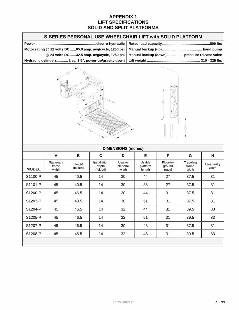
32DSSP02.C 4 - 23
APPENDIX 1 LIFT SPECIFICATIONS
SOLID AND SPLIT PLATFORMS
S-SERIES PERSONAL USE WHEELCHAIR LIFT with SOLID PLATFORM Power ............................................................. electro-hydraulic
Motor rating @ 12 volts DC ......65.0 amp. avg/cycle, 1250 psi
@ 24 volts DC ......32.5 amp. avg/cycle, 1250 psi
Hydraulic cylinders ........... 2 ea, 1.5", power-up/gravity-down
Rated load capacity.................................................800 lbs
Manual backup (up)......................................... hand pump
Manual backup (down)................. pressure release valve
Lift weight ...................................................... 310 - 325 lbs
DIMENSIONS (inches)
A B C D E F G H
MODEL Stationary
frame width
Height (folded)
Installation depth
(folded)
Usable platform
width
Usable platform length
Floor-to-ground travel
Traveling frame width
Clear entry width
S1100-P 45 40.5 14 30 44 27 37.5 31
S1101-P 45 40.5 14 30 38 27 37.5 31
S1200-P 45 46.5 14 30 44 31 37.5 31
S1203-P 45 49.5 14 30 51 31 37.5 31
S1204-P 45 46.5 14 32 44 31 39.5 33
S1205-P 45 46.5 14 32 51 31 39.5 33
S1207-P 45 46.5 14 30 48 31 37.5 31
S1208-P 45 46.5 14 32 48 31 39.5 33

32DSSP02.C 4 - 24
S-SERIES PERSONAL USE WHEELCHAIR LIFT with SPLIT PLATFORM Power ............................................................. electro-hydraulic
Motor rating @ 12 volts DC ..... 65.0 amp. avg/cycle, 1250 psi
@ 24 volts DC ..... 32.5 amp. avg/cycle, 1250 psi
Hydraulic cylinders ...........2 ea, 1.5", power-up/gravity-down
Rated load capacity................................................ 800 lbs
Manual backup (up)......................................... hand pump
Manual backup (down)................. pressure release valve
Lift weight ...................................................... 300 - 325 lbs
DIMENSIONS (inches)
A B C D E F G H
MODEL Stationary
frame width
Height (folded)
Installation depth
(folded)
Usable platform
width
Usable platform length
Floor-to-ground travel
Traveling frame width
Clear entry width
S1132-P 41 40.5 19.5 26 38 27 33.5 27
S1133-P 45 40.5 21.5 30 38 27 37.5 31
S1230-P 45 46.5 21.5 30 48 31 37.5 31
S1231-P 45 44.5 21.5 30 42 31 37.5 31