Embed Size (px)
Citation preview

INNOVATION IN THEWAKE OF TRADITION
GVX2000
I N V E RT E R
®®
CTÜ
V R
hein
land
Pro
duct
Saf
ety
BA
UA
RT
GEP
RÜ
FT
TYP
EA
PP
RO
VED
GSX6000.4-2.2 kW
GVX9000.2-4 kW
GVX20000.55-500 kW
LMS0.4-4 kW
POW
ER
IN M
OTIO
N
POW
ER
IN M
OTIO
N
COMPLETE AND
ADVANCED SOLUTIONS
IN POWER TRANSMISSION
FOR ANY INTELLIGENT
AND HIGH EFFICIENT APPLICATION

GSX6000.4-2.2 kW
GVX9000.2-4 kW
GVX20000.55-500 kW
LMS0.4-4 kW
POW
ER
IN M
OTIO
N
POW
ER
IN M
OTIO
N
COMPLETE AND
ADVANCED SOLUTIONS
IN POWER TRANSMISSION
FOR ANY INTELLIGENT
AND HIGH EFFICIENT APPLICATION

GVX20002 3
Dynamic torque-vector control system performs high-speed calculation to determine the required motor power for theload status. Our key technology is optimal control of voltage and current vectors for maximum output torque.• The torque values obtained with an inverter GVX2000 for high performances applications are: • 250% of rated motor torque on short period • 200% of rated motor torque at 0.5Hz (180% for models over 30kW)• Achieves smooth acceleration/deceleration in the shortest time for the load condition.• Using a high-speed CPU, quickly responds to an abrupt load change, detects the regenerated power to control the
deceleration time. This automatic deceleration function greatly reduces the inverter tripping.• Feedback control with PG, enables the inverter to execute “vector control with PG” by adding an optional PG feedback
card to obtain higher performances of starting torque and control precision:• Speed control range: 1:1200• Speed control accuracy: ±0.02%• Speed control response: 40Hz - (25kW or smaller)
Motor wow at low speed (1Hz) reduced to less than 1/2 of that achieved by conventional inverters, with the dynamictorque-vector control system, in combination with the unique digital AVR.
• On-line tuning to continuously check for variation ofmotor characteristics during running for high-precisionspeed control.
• This tuning function also available for a second motor,which allows high-precision driving of the second motorby changeover operation between two motors.
Torque characteristics with Dynamic torque-vector control(sample: 5.5 kW)
Out
put t
orqu
e [%
]
300
Motor speed[r/min]
200
100
0
100
200
300
1000 2000
Previous Series Inverter
Wow characterisics (sample: 5.5 kW)
0
0 14 r/min
5 r/min
500ms
GVX2000
Time
Motor temperature vs speed variation (sample: 5.5 kW)
30°C
70°C
800
Mot
or s
peed
[r/m
in]
Time [min]
Tem
pera
ture
[C]
°
With on-line tuning
Without on-line tuning
5,5 kW
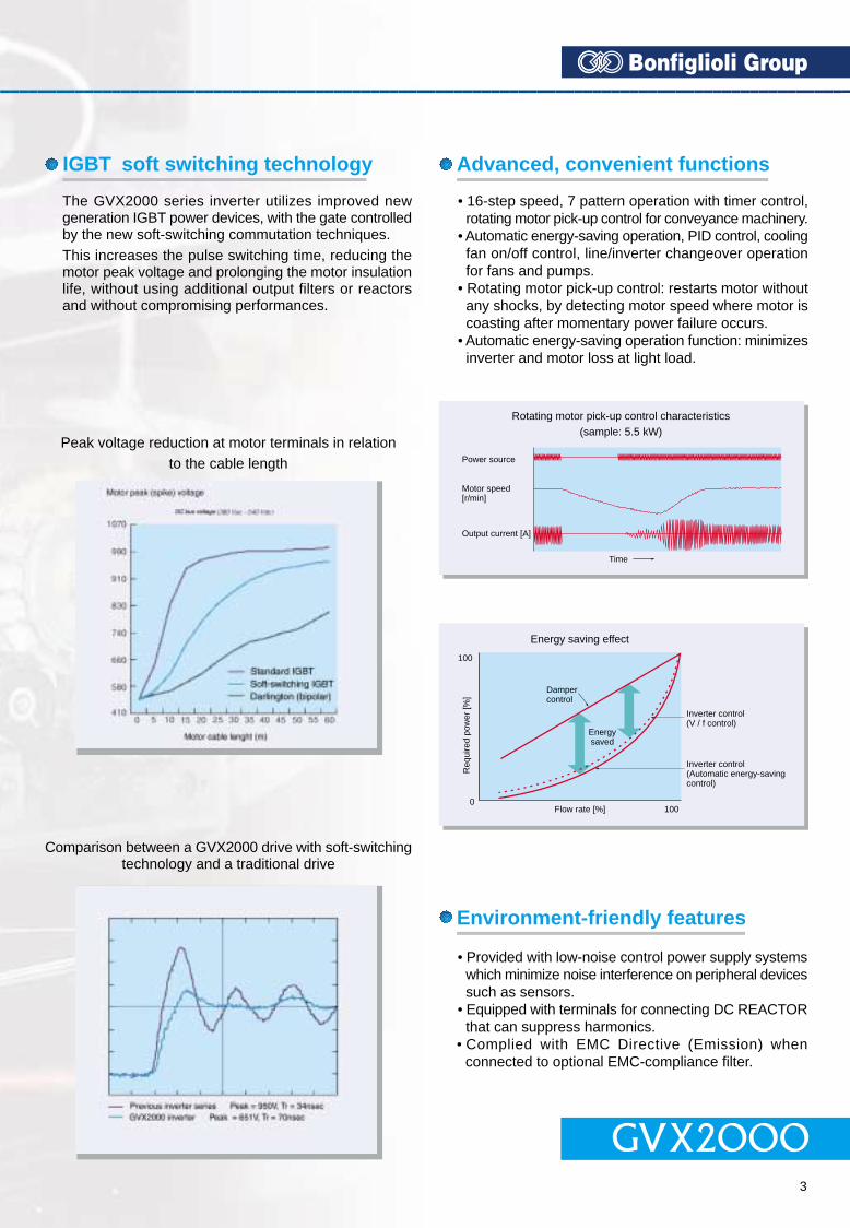
• Provided with low-noise control power supply systemswhich minimize noise interference on peripheral devicessuch as sensors.
• Equipped with terminals for connecting DC REACTORthat can suppress harmonics.
• Complied with EMC Directive (Emission) whenconnected to optional EMC-compliance filter.
• 16-step speed, 7 pattern operation with timer control,rotating motor pick-up control for conveyance machinery.
• Automatic energy-saving operation, PID control, coolingfan on/off control, line/inverter changeover operationfor fans and pumps.
• Rotating motor pick-up control: restarts motor withoutany shocks, by detecting motor speed where motor iscoasting after momentary power failure occurs.
• Automatic energy-saving operation function: minimizesinverter and motor loss at light load.
Power source
Motor speed[r/min]
Output current [A]
Time
Rotating motor pick-up control characteristics
(sample: 5.5 kW)
Dampercontrol
Energysaved
Inverter control(V / f control)
Inverter control(Automatic energy-savingcontrol)
Flow rate [%]
Energy saving effect
0
100
100
Req
uire
d po
wer
[%]
PG Vector Control
Step load response (sample : 5.5 kW)
Actual torque [%]
Torque reference
[%]
Motor speed [r/min]
320msTime
100
0
100
0
500
400
10
0
The GVX2000 series inverter utilizes improved newgeneration IGBT power devices, with the gate controlledby the new soft-switching commutation techniques.This increases the pulse switching time, reducing themotor peak voltage and prolonging the motor insulationlife, without using additional output filters or reactorsand without compromising performances.
Peak voltage reduction at motor terminals in relationto the cable length
Comparison between a GVX2000 drive with soft-switchingtechnology and a traditional drive
Dynamic torque-vector control
Reduced motor wow at low speed
Reduced motor wow at low speed
Environment-friendly features
Advanced, convenient functionsIGBT soft switching technology
GVX20002 3
Dynamic torque-vector control system performs high-speed calculation to determine the required motor power for theload status. Our key technology is optimal control of voltage and current vectors for maximum output torque.• The torque values obtained with an inverter GVX2000 for high performances applications are: • 250% of rated motor torque on short period • 200% of rated motor torque at 0.5Hz (180% for models over 30kW)• Achieves smooth acceleration/deceleration in the shortest time for the load condition.• Using a high-speed CPU, quickly responds to an abrupt load change, detects the regenerated power to control the
deceleration time. This automatic deceleration function greatly reduces the inverter tripping.• Feedback control with PG, enables the inverter to execute “vector control with PG” by adding an optional PG feedback
card to obtain higher performances of starting torque and control precision:• Speed control range: 1:1200• Speed control accuracy: ±0.02%• Speed control response: 40Hz - (25kW or smaller)
Motor wow at low speed (1Hz) reduced to less than 1/2 of that achieved by conventional inverters, with the dynamictorque-vector control system, in combination with the unique digital AVR.
• On-line tuning to continuously check for variation ofmotor characteristics during running for high-precisionspeed control.
• This tuning function also available for a second motor,which allows high-precision driving of the second motorby changeover operation between two motors.
Torque characteristics with Dynamic torque-vector control(sample: 5.5 kW)
Out
put t
orqu
e [%
]
300
Motor speed[r/min]
200
100
0
100
200
300
1000 2000
Previous Series Inverter
Wow characterisics (sample: 5.5 kW)
0
0 14 r/min
5 r/min
500ms
GVX2000
Time
Motor temperature vs speed variation (sample: 5.5 kW)
30°C
70°C
800
Mot
or s
peed
[r/m
in]
Time [min]
Tem
pera
ture
[C]
°
With on-line tuning
Without on-line tuning
5,5 kW
• Provided with low-noise control power supply systemswhich minimize noise interference on peripheral devicessuch as sensors.
• Equipped with terminals for connecting DC REACTORthat can suppress harmonics.
• Complied with EMC Directive (Emission) whenconnected to optional EMC-compliance filter.
• 16-step speed, 7 pattern operation with timer control,rotating motor pick-up control for conveyance machinery.
• Automatic energy-saving operation, PID control, coolingfan on/off control, line/inverter changeover operationfor fans and pumps.
• Rotating motor pick-up control: restarts motor withoutany shocks, by detecting motor speed where motor iscoasting after momentary power failure occurs.
• Automatic energy-saving operation function: minimizesinverter and motor loss at light load.
Power source
Motor speed[r/min]
Output current [A]
Time
Rotating motor pick-up control characteristics
(sample: 5.5 kW)
Dampercontrol
Energysaved
Inverter control(V / f control)
Inverter control(Automatic energy-savingcontrol)
Flow rate [%]
Energy saving effect
0
100
100
Req
uire
d po
wer
[%]
PG Vector Control
Step load response (sample : 5.5 kW)
Actual torque [%]
Torque reference
[%]
Motor speed [r/min]
320msTime
100
0
100
0
500
400
10
0
The GVX2000 series inverter utilizes improved newgeneration IGBT power devices, with the gate controlledby the new soft-switching commutation techniques.This increases the pulse switching time, reducing themotor peak voltage and prolonging the motor insulationlife, without using additional output filters or reactorsand without compromising performances.
Peak voltage reduction at motor terminals in relationto the cable length
Comparison between a GVX2000 drive with soft-switchingtechnology and a traditional drive
Dynamic torque-vector control
Reduced motor wow at low speed
Reduced motor wow at low speed
Environment-friendly features
Advanced, convenient functionsIGBT soft switching technology

GVX20004 5
• Conforms to major world safety standards: CE, UL, cUL, TÜV, C-Tick.• Equipped with RS485 interface as standard.• Connection to field bus: Profibus-DP, Interbus-S, DeviceNet, Modbus Plus and others, with the ANY-BUS option.• Universal DI/DO: monitors digital I/O signal status and transmits to a host controller, helping to simplify factory automation.
• Copy function: easily copies function codes and data to other inverters.• Six languages (English, French, German, Italian, Spanish, and Japanese) are available as standard.• Jogging (inching) operation from the Keypad or external signal• Remote operation using optional extension cable (1,5 to 10m)
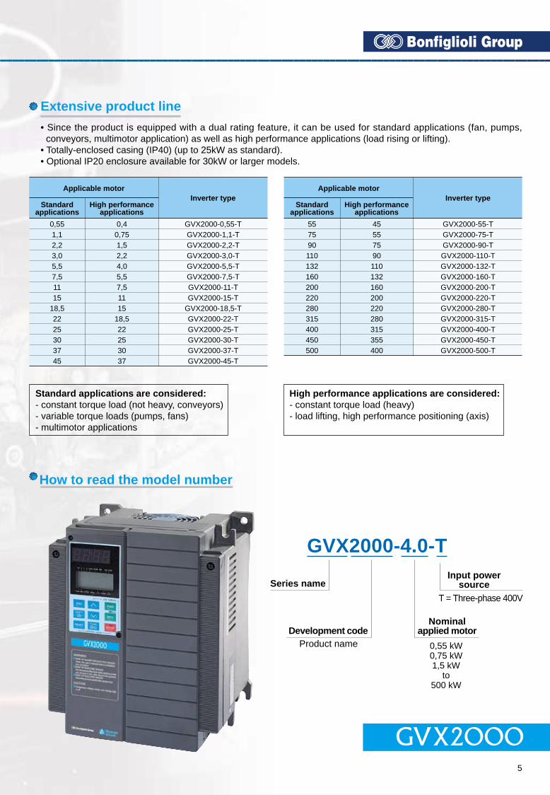
• Since the product is equipped with a dual rating feature, it can be used for standard applications (fan, pumps,conveyors, multimotor application) as well as high performance applications (load rising or lifting).
• Totally-enclosed casing (IP40) (up to 25kW as standard).• Optional IP20 enclosure available for 30kW or larger models.
• Side-by-side mounting (up to 25kW) saves space wheninverters are installed in a panel.
• The uniform height (260mm) of products (up to 11kW)makes it easy to design panels.
• User-definable control terminals: digital input (9 points),transistor output (4 points), relay contact output (1 point),and alarm relay contact output.
• Active drive feature: performs prolonged accelerationat reduced torque, monitoring the load status to preventtripping.
• Stall prevention function is provided as standard. Activeor inactive can be also selected.
Protection• Motors with various characteristics can be used by
setting thermal time constant for the electronic thermaloverload relay.
• Input phase loss protective function protects the inverterfrom damage caused by disconnection of power supplylines.
• Motor is protected with a PTC thermistor.• Input terminals for auxiliary control power supply (2.2
kW or larger models) : alarm signal output will be heldeven if main circuit power supply has shut down.
Excellent maintainabilityThe items below can be monitored on the Keypad paneland making it easy to analyze the cause of trip and totake preventive measures.• Input/output terminals check• Life expectancy of main-circuit capacitors• Inverter on-load factor• Accumlated operation time• Inverter operating condition (output current, heat sink
temperature, input power, etc.)• Detailed data on trip cause
200
10090
50
1 6 15 20 50 100
Torque characteristics with Dynamic torque-vector control100% of output torque refers to the rated torque of the motor driven at 50Hz.
Short time operationtorqueContinuous operation
torque
0.55 to2.2kW
3.0 to25kW
Output frequency [Hz]
Out
put t
orqu
e [%
]
Applicable motorInverter type
0,551,12,23,05,57,51115
18,52225303745
Standardapplications
High performanceapplications
0,40,751,52,24,05,57,51115
18,522253037
GVX2000-0,55-TGVX2000-1,1-TGVX2000-2,2-TGVX2000-3,0-TGVX2000-5,5-TGVX2000-7,5-TGVX2000-11-TGVX2000-15-T
GVX2000-18,5-TGVX2000-22-TGVX2000-25-TGVX2000-30-TGVX2000-37-TGVX2000-45-T
Applicable motorInverter type
557590110132160200220280315400450500
Standardapplications
High performanceapplications
45557590110132160200220280315355400
GVX2000-55-TGVX2000-75-TGVX2000-90-TGVX2000-110-TGVX2000-132-TGVX2000-160-TGVX2000-200-TGVX2000-220-TGVX2000-280-TGVX2000-315-TGVX2000-400-TGVX2000-450-TGVX2000-500-T
Standard applications are considered:- constant torque load (not heavy, conveyors)- variable torque loads (pumps, fans)- multimotor applications
High performance applications are considered:- constant torque load (heavy)- load lifting, high performance positioning (axis)
GVX2000-4.0-T
Series name
Development codeProduct name
Nominalapplied motor
0,55 kW0,75 kW1,5 kW
to500 kW
Input powersource
T = Three-phase 400V
How to read the model number
Global products, communication
Intelligent Keypad panel
Protective functions, Maintenance
Extensive product line
Other useful functions
RUNRUN
WARNINGRISK OF INJURY OR ELECTRIC SHOCKRolor yhe user’s manual bolone instructionand operation.RISK OF ELECTRIC SHOKDo not remove the cover whte oppyng power and at cast 5 min. doconneng powerRISK OF ELECTRIC SHOCKScourety ground the equimpent
CAUTIONDangnous voltage unil change light bolt
GVX2000
RUNRUN
GVX20004 5
• Conforms to major world safety standards: CE, UL, cUL, TÜV, C-Tick.• Equipped with RS485 interface as standard.• Connection to field bus: Profibus-DP, Interbus-S, DeviceNet, Modbus Plus and others, with the ANY-BUS option.• Universal DI/DO: monitors digital I/O signal status and transmits to a host controller, helping to simplify factory automation.
• Copy function: easily copies function codes and data to other inverters.• Six languages (English, French, German, Italian, Spanish, and Japanese) are available as standard.• Jogging (inching) operation from the Keypad or external signal• Remote operation using optional extension cable (1,5 to 10m)
• Since the product is equipped with a dual rating feature, it can be used for standard applications (fan, pumps,conveyors, multimotor application) as well as high performance applications (load rising or lifting).
• Totally-enclosed casing (IP40) (up to 25kW as standard).• Optional IP20 enclosure available for 30kW or larger models.
• Side-by-side mounting (up to 25kW) saves space wheninverters are installed in a panel.
• The uniform height (260mm) of products (up to 11kW)makes it easy to design panels.
• User-definable control terminals: digital input (9 points),transistor output (4 points), relay contact output (1 point),and alarm relay contact output.
• Active drive feature: performs prolonged accelerationat reduced torque, monitoring the load status to preventtripping.
• Stall prevention function is provided as standard. Activeor inactive can be also selected.
Protection• Motors with various characteristics can be used by
setting thermal time constant for the electronic thermaloverload relay.
• Input phase loss protective function protects the inverterfrom damage caused by disconnection of power supplylines.
• Motor is protected with a PTC thermistor.• Input terminals for auxiliary control power supply (2.2
kW or larger models) : alarm signal output will be heldeven if main circuit power supply has shut down.
Excellent maintainabilityThe items below can be monitored on the Keypad paneland making it easy to analyze the cause of trip and totake preventive measures.• Input/output terminals check• Life expectancy of main-circuit capacitors• Inverter on-load factor• Accumlated operation time• Inverter operating condition (output current, heat sink
temperature, input power, etc.)• Detailed data on trip cause
200
10090
50
1 6 15 20 50 100
Torque characteristics with Dynamic torque-vector control100% of output torque refers to the rated torque of the motor driven at 50Hz.
Short time operationtorqueContinuous operation
torque
0.55 to2.2kW
3.0 to25kW
Output frequency [Hz]
Out
put t
orqu
e [%
]
Applicable motorInverter type
0,551,12,23,05,57,51115
18,52225303745
Standardapplications
High performanceapplications
0,40,751,52,24,05,57,51115
18,522253037
GVX2000-0,55-TGVX2000-1,1-TGVX2000-2,2-TGVX2000-3,0-TGVX2000-5,5-TGVX2000-7,5-TGVX2000-11-TGVX2000-15-T
GVX2000-18,5-TGVX2000-22-TGVX2000-25-TGVX2000-30-TGVX2000-37-TGVX2000-45-T
Applicable motorInverter type
557590110132160200220280315400450500
Standardapplications
High performanceapplications
45557590110132160200220280315355400
GVX2000-55-TGVX2000-75-TGVX2000-90-TGVX2000-110-TGVX2000-132-TGVX2000-160-TGVX2000-200-TGVX2000-220-TGVX2000-280-TGVX2000-315-TGVX2000-400-TGVX2000-450-TGVX2000-500-T
Standard applications are considered:- constant torque load (not heavy, conveyors)- variable torque loads (pumps, fans)- multimotor applications
High performance applications are considered:- constant torque load (heavy)- load lifting, high performance positioning (axis)
GVX2000-4.0-T
Series name
Development codeProduct name
Nominalapplied motor
0,55 kW0,75 kW1,5 kW
to500 kW
Input powersource
T = Three-phase 400V
How to read the model number
Global products, communication
Intelligent Keypad panel
Protective functions, Maintenance
Extensive product line
Other useful functions
RUNRUN
WARNINGRISK OF INJURY OR ELECTRIC SHOCKRolor yhe user’s manual bolone instructionand operation.RISK OF ELECTRIC SHOKDo not remove the cover whte oppyng power and at cast 5 min. doconneng powerRISK OF ELECTRIC SHOCKScourety ground the equimpent
CAUTIONDangnous voltage unil change light bolt
GVX2000
RUNRUN

GVX20006 7
0.55Type
Standard application 1) [kW]
App
lied
mot
or
1.1 2.2 3.0 5.5 7.5 11 15 18.5 22 25
0.55 1.1 2.2 3.0 5.5 7.5 11 15 18.5 22 25
High performance 1) [kW]application
0.4 0.75 1.5 2.2 4.0 5.5 7.5 11 15 18.5 22
Rated capacity 2) [kVA] 1.0 1.7 2.6 3.9 6.4 9.3 12 17 21 28 32
Rated voltage 3) [V] 3-phase 320 to 480 V (output voltage cannot exceed the power supply voltage)
Out
put r
atin
gs
Ratedcurrent 4) 5) [A]
1.9 3.1 4.6 6.8 11.2 16.5 23 30 37 44 54Standardapplications
1.5 2.5 3.7 5.5 9 13 18 24 30 39 45High performanceapplication
150% of motor rated torque for 1 min. 9)200% of motor rated torque on the short period
Standardapplications
150% of motor rated torque for 1 min.250% of motor rated torque on the short period
High performanceapplication
Torqueoverload
Inpu
t rat
ings
Rated frequency [Hz] 50, 60Hz
Phase, voltage, frequency 3-phase 380 to 480 V 50/60 Hz
Voltage/frequency variation Voltage: +10 to -15% (voltage unbalance 2% or less) 6) Frequency: +5 to -5%
When the input voltage is 310 V or more, the inverter can be operated continuously.When the input voltage drops below 310 V from rated voltage, the inverter can be operated for 15 ms.
The smooth recovery method is selectable.Momentary voltage dip capability 7)
Rated current [A](With DCR) 0.62 1.5 2.9 4.2 7.1 10.0 13.5 19.8 26.8 33.2 39.3
(Without DCR) 1.8 3.5 6.2 9.2 14.9 21.5 27.9 39.1 50.3 59.9 69.3
Required power supply capacity(with DCR) [kVA] 0.6 1.1 2.1 3.0 5.0 7.0 9.4 14 19 24 28
150%Standardapplications
200% (with dynamic torque-vector control selected)High performanceapplication
Starting torque
Con
trol
Bra
kin
g
Braking torque 150%
Time [s]
Duty cicle [%]Sta
nd
ard
Braking torque (Using Option)
Dc injection braking
100% 20% 8)
No limit
No limit
5 5
5 3 5 3 2 3 2
150%
Starting frequency: 0.1 to 60.0 Hz Braking time: 0.0 to 30.0 sBraking level: 0 to 100% of rated current
Enclosure (IEC605297)
Coooling method
IP40
Natural cooling Fan cooling
Standars
Mass [kg] 2.2 2.5 3.8 3.8 3.8 6.5 6.5 10 10 10.5 10.5
Notes:
1) Standard applications are considered:- constant torque load (not heavy, conveyors)- variable torque loads (pumps, fans)- multimotor applications
2) Inverter output capacity [kVA] at 415 V.3) Output voltage is proportional to the power supply voltage and cannot exceed the power supply voltage.4) When selecting an inverter, the rated current of the motor applied, shall be equal or lower than this output current value. If this condition cannotbe applied, use the motor under a load factor (%) calculated as follows: load factor (%) = [ inverter output current ] / [ Motor output current ] x 100.5) Current derating may be required in case of low impedance load such as high frequency motor.6) Refer to the EN61800-3 (5.2.3).7) Tested at standard load condition (85% load).8) With a nominal applied motor, this value is average torque when the motor deceierates and stops from 60 Hz (it may change according to motor loss).9) With the setting of carrier frequency (motor sound) at less than 8 kHz and maximum temperature 40 °C.
High performance applications are considered:- constant torque load (heavy)- load lifting, high performance positioning (axis)
30Type
Standard application 1) [kW]
App
lied
mot
or
37 45 55 75 90 110 132 160 200 220
30 37 45 55 75 90 110 132 160 200
High performance 1) [kW]application
25 30 37 45 55 75 90 110 132 160
Rated capacity 2) [kVA] 32 43 53 65 80 107 126 150 181 218
Rated voltage 3) [V] 3-phase 320 to 480 V (output voltage cannot exceed the power supply voltage)
Out
put r
atin
gs
Ratedcurrent 4) 5) [A]
Standardapplications
High performanceapplication
Standardapplications
High performanceapplication
Torqueoverload
Inpu
t rat
ings
Rated frequency [Hz] 50, 60Hz
Phase, voltage, frequency 3-phase 380 to 480 V 50/60 Hz
Voltage/frequency variation Voltage: +10 to -15% (voltage unbalance 2% or less) 7) Frequency: +5 to -5%
When the input voltage is 310 V or more, the inverter can be operated continuously.When the input voltage drops below 310 V from rated voltage, the inverter can be operated for 15 ms.
The smooth recovery method is selectable.Momentary voltage dip capability 7)
Rated current [A](With DCR) 54 54 67 81 100 134 282 352 491 552 704
(Without DCR) 86 86 104 124 150 - - - - - -
Required power supply capacity(with DCR) [kVA] 38 38 47 57 70 93 196 244 341 383 488
150%Standardapplications
200% (with dynamic torque-vector control selected)High performanceapplication
Starting torque
Con
trol
Bra
kin
g
Braking torque
Time [s]
Duty cicle [%]Sta
ndar
d
Braking torque (Using Option)
Dc injection braking
15 to 10% 9)
No limit
No limit
100%
Starting frequency: 0.1 to 60.0 Hz Braking time: 0.0 to 30.0 s Braking level: 0 to 100% of rated current
Enclosure (IEC605297)
Coooling method
IP00 (IP20: option)
Fan cooling
Standars
Mass [kg] 31 31 36 41 42 50 73 73 250 250 360
Notes:
1) Standard applications are considered:- constant torque load (not heavy, conveyors)- variable torque loads (pumps, fans)- multimotor applications
High performance applications are considered:- constant torque load (heavy)- load lifting, high performance positioning (axis)
280 315 400 450
500
220
200
270
280
220
298
315
280
373
400
315
420
450
355
467
500
400
532
50 75 91 112 150 176 210 253 304 377 415 520 585 650 740 840
- 60 75 91 112 150 176 210 253 304 377 415 520 585 650 740
104 104 145 145 360
160
-
111
156
-
136
232
-
161
385
-
267
624
-
432
- UL/cUL - CE Marking (EM, Low Voltage) - EN 61800-3 - T ÜV-EN 61800-2 - C-Tick - UL/cUL - CE Marking (EM, Low Voltage) - EN 61800-3 - T ÜV-EN 61800-2 - C-Tick
30 EV
30 37 45 55 75 90 110 132 160 200 220 280 315 400 450
COMMON SPECIFICATIONS (0.55 - 25 W) COMMON SPECIFICATIONS (30 - 500 W)
GVX2000- -T GVX2000- -T
FUJI FRN G11S-4EN
150% of motor rated torque for 1 min. 10)200% of motor rated torque on the short period
150% of motor rated torque for 1 min.250% of motor rated torque on the short period
2) Inverter output capacity [kVA] at 415 V.3) Output voltage is proportional to the power supply voltage and cannot exceed the power supply voltage.4) When selecting an inverter, the rated current of the motor applied, shall be equal or lower than this output current value. If this condition cannot
be applied, use the motor under a load factor (%) calculated as follows: load factor (%) = [ inverter output current ] / [ Motor output current ] x100.5) Current derating may be required in case of low impedance loads such as high frequency motor.6) When the input voltage is between 440 and 480 V / 50Hz, the tap of the auxiliary transformer must be changed7) Refer to the EN61800-3 (5.2.3).8) Tested at standard load condition (85% load).9) With a nominal applied motor, this value is average torque when the motor deceierates and stops
from 60 Hz (it may change according to motor loss).10) With the setting of carrier frequency (motor sound) at less than 8 kHz and maximum temperature 40°C.
GVX20008 9
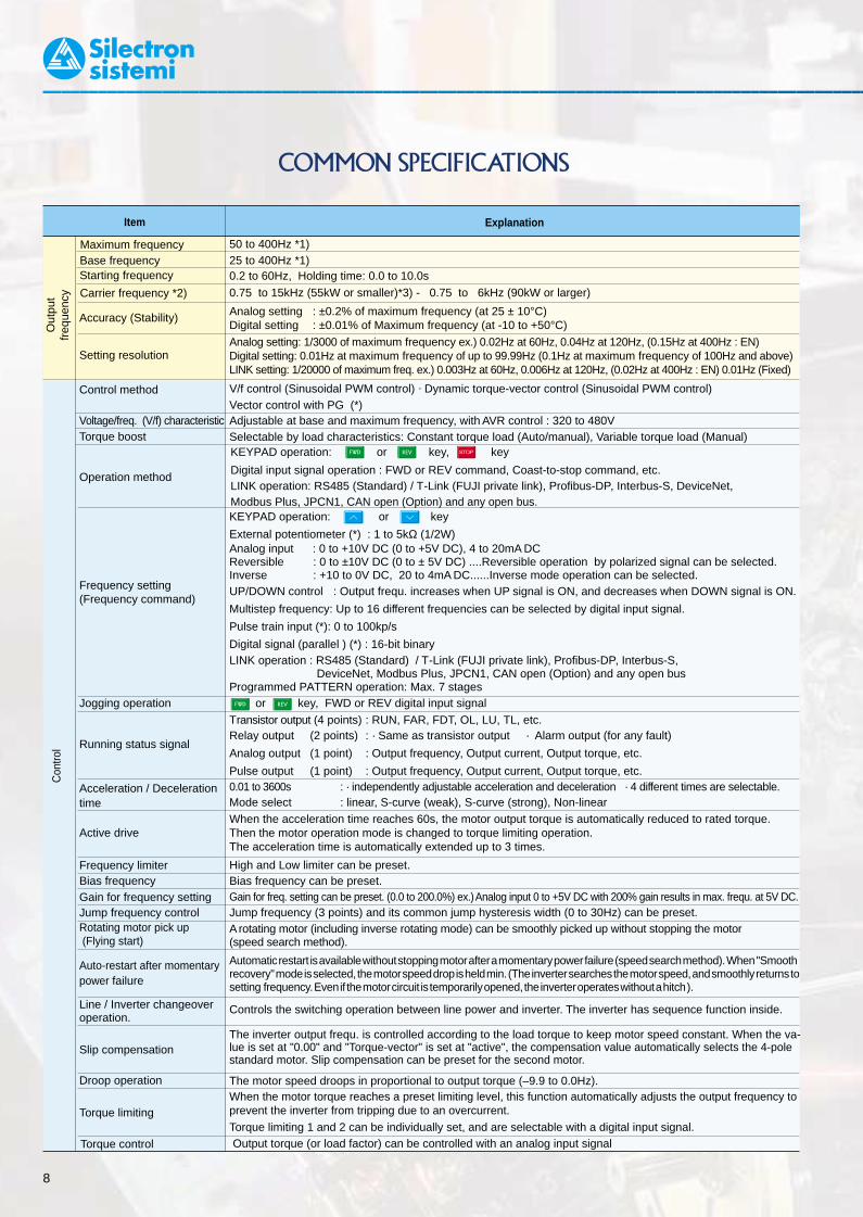
COMMON SPECIFICATIONS
PID control
This function can control flowrate, pressure, etc. (with an analog feedback signal.)• Reference · KEYPAD operat. ( or key) : Setting freq. / Max. freq. X 100 (%) · PATTERN operation : Settingsignal · Voltage input (Terminal 12 and V2 ) : 0 to +10V DC freq./Max. freq. X 100 (%) · Current input (Terminal C1 ) : 4 to 20mA DC · DI option input (*) : · BCD,
· Reversible operation with polarity (Terminal 12) : 0 to ±10V DC setting freq./Max.freq. X 100 (%) · Reversible operation with polar. (Terminal 12 + V1 ) : 0 to ±10V DC · Binary, full scale/100 (%)
· Inverse mode operation (Terminal 12 and V2 ) : +10 to 0V DC · Multistep frequ. setting : · Inverse mode operation (Terminal C1) : 20 to 4mA DC Setting freq./Max.
RS485 : Setting freq./Max. freq. X 100 (%) ·freq. X 100 (%)
• Feedback signal · Terminal 12 (0 to +10V DC or +10 to 0V DC)· Terminal C1 (4 to 20mA DC or 20 to 4mA DC)
Item Explanation
Out
put
freq
uenc
yC
ontro
l
Accuracy (Stability)
Maximum frequencyBase frequencyStarting frequency
Carrier frequency *2)
Setting resolution
Control method
Voltage/freq. (V/f) characteristicTorque boost
Operation method
Frequency setting(Frequency command)
Jogging operation
Running status signal
Acceleration / Decelerationtime
Active drive
Frequency limiterBias frequencyGain for frequency settingJump frequency controlRotating motor pick up (Flying start)
Auto-restart after momentarypower failure
Line / Inverter changeoveroperation.
Slip compensation
Droop operation
Torque limiting
50 to 400Hz *1)25 to 400Hz *1)0.2 to 60Hz, Holding time: 0.0 to 10.0s
0.75 to 15kHz (55kW or smaller)*3) - 0.75 to 6kHz (90kW or larger)
Analog setting : ±0.2% of maximum frequency (at 25 ± 10°C)Digital setting : ±0.01% of Maximum frequency (at -10 to +50°C)
Analog setting: 1/3000 of maximum frequency ex.) 0.02Hz at 60Hz, 0.04Hz at 120Hz, (0.15Hz at 400Hz : EN)Digital setting: 0.01Hz at maximum frequency of up to 99.99Hz (0.1Hz at maximum frequency of 100Hz and above)LINK setting: 1/20000 of maximum freq. ex.) 0.003Hz at 60Hz, 0.006Hz at 120Hz, (0.02Hz at 400Hz : EN) 0.01Hz (Fixed)
V/f control (Sinusoidal PWM control) · Dynamic torque-vector control (Sinusoidal PWM control)Vector control with PG (*)Adjustable at base and maximum frequency, with AVR control : 320 to 480VSelectable by load characteristics: Constant torque load (Auto/manual), Variable torque load (Manual)
KEYPAD operation: or key
External potentiometer (*) : 1 to 5kΩ (1/2W)Analog input : 0 to +10V DC (0 to +5V DC), 4 to 20mA DCReversible : 0 to ±10V DC (0 to ± 5V DC) ....Reversible operation by polarized signal can be selected.Inverse : +10 to 0V DC, 20 to 4mA DC......Inverse mode operation can be selected.UP/DOWN control : Output frequ. increases when UP signal is ON, and decreases when DOWN signal is ON.
Multistep frequency: Up to 16 different frequencies can be selected by digital input signal.
Pulse train input (*): 0 to 100kp/s
Digital signal (parallel ) (*) : 16-bit binaryLINK operation : RS485 (Standard) / T-Link (FUJI private link), Profibus-DP, Interbus-S,
DeviceNet, Modbus Plus, JPCN1, CAN open (Option) and any open busProgrammed PATTERN operation: Max. 7 stages
or key, FWD or REV digital input signal
Transistor output (4 points) : RUN, FAR, FDT, OL, LU, TL, etc.Relay output (2 points) : · Same as transistor output · Alarm output (for any fault)
Analog output (1 point) : Output frequency, Output current, Output torque, etc.
Pulse output (1 point) : Output frequency, Output current, Output torque, etc.0.01 to 3600s : · independently adjustable acceleration and deceleration · 4 different times are selectable.Mode select : linear, S-curve (weak), S-curve (strong), Non-linearWhen the acceleration time reaches 60s, the motor output torque is automatically reduced to rated torque.Then the motor operation mode is changed to torque limiting operation.The acceleration time is automatically extended up to 3 times.
High and Low limiter can be preset.Bias frequency can be preset.Gain for freq. setting can be preset. (0.0 to 200.0%) ex.) Analog input 0 to +5V DC with 200% gain results in max. frequ. at 5V DC.Jump frequency (3 points) and its common jump hysteresis width (0 to 30Hz) can be preset.A rotating motor (including inverse rotating mode) can be smoothly picked up without stopping the motor(speed search method).
Automatic restart is available without stopping motor after a momentary power failure (speed search method). When "Smoothrecovery" mode is selected, the motor speed drop is held min. (The inverter searches the motor speed, and smoothly returns tosetting frequency. Even if the motor circuit is temporarily opened, the inverter operates without a hitch ).
Controls the switching operation between line power and inverter. The inverter has sequence function inside.
The inverter output frequ. is controlled according to the load torque to keep motor speed constant. When the va-lue is set at "0.00" and "Torque-vector" is set at "active", the compensation value automatically selects the 4-polestandard motor. Slip compensation can be preset for the second motor.
The motor speed droops in proportional to output torque (–9.9 to 0.0Hz).When the motor torque reaches a preset limiting level, this function automatically adjusts the output frequency toprevent the inverter from tripping due to an overcurrent.
Torque limiting 1 and 2 can be individually set, and are selectable with a digital input signal.
KEYPAD operation: or key, key
Digital input signal operation : FWD or REV command, Coast-to-stop command, etc.LINK operation: RS485 (Standard) / T-Link (FUJI private link), Profibus-DP, Interbus-S, DeviceNet,Modbus Plus, JPCN1, CAN open (Option) and any open bus.
Item Explanation
Torque control Output torque (or load factor) can be controlled with an analog input signal
Con
trol Automatic deceleration
Torque limiter 1 (Braking) is set at "F41: 0" (Same as Torque limiter 2 (Braking) ).· In deceleration: the deceleration time is automatically extended up to 3 times the setting time for tripless operation even if braking resistor not used.· In constant speed operation: Based on regenerative energy, the frequ. is increased and tripless operation is active.
Second motor ’s settingThis function is used for two motors switching operation.· The second motor ’s V/f characteristics (base and maximum frequency) can be preset.· The second motor ’s circuit parameter can be preset. Torque-vector control can be applied to both motors.
Energy saving operation This function minimizes inverter and motor losses at light load.Fan stop operation
Universal DI
Universal DO
Zero speed control (*)
Positioning control (*)
This function is used for silent operation or extending the fan's lifetime.Transmits to main controller of LINK operation.Outputs command signal from main controller of LINK operation.Outputs analog signal from main controller of LINK operation.The motor speed is controlled with the speed reference of zero.The SY option card can be used for positioning control by differential counter method.This function controls the synchronized operation between 2 axes with PGs.Synchronized operation (*)
Universal AO
Indi
catio
n
Operation mode (Running)
LED monitorLCD monitor
(English, German, French, Spanish, Italian, Japanese)
· Output frequency 1 (Before slip compensation) (Hz)· Output frequency 2 (After slip compensation) (Hz)· Setting frequency (Hz)· Output current (A)· Output voltage (V)· Motor synchronous speed (r/min)· Line speed (m/min)· Load shaft speed (r/min)· Torque calculation value (%)· Input power (kW)· PID reference value ("F01")· PID reference value (Remote) ("C30")· PID feedback value
· Trip history :Cause of trip by code (Even when main power supply is off, trip history data of the last 4 tripsare retained.)
Stopping Selected setting value or output value
Trip mode
Displays the cause of trip by codes as follows.· OC1 (Overcurrent during acceleration). OC2 (Overcurrent during deceleration)· OC3 (Overcurrent running at constant speed)· EF (Ground fault)· Lin (Input phase loss)· FUS (Fuse blown)· OU1 (Overvoltage during acceleration)· OU2 (Overvoltage during deceleration)· OU3 (Overvoltage running at constant speed)· LU (Undervoltage)· OH1 (Overheating at heat sink)· OH2 (External thermal relay tripped)· OH3 (Overtemperature at inside air)
Operation monitor & Alarm monitor
Operation monitor· Displays operation guidance· Bargraph: Output frequency (%), Output current (A),
Output torque (%)Alarm monitor
· The alarm data is displayed when the inverter trips.
Function setting & monitor
Function settingDisplays function codes and its data or data code, and changes the data value. Operation condition· Output frequency (Hz) · Motor synchronous speed
(r/min)· Output current (A) · Load shaft speed (r/min)· Output voltage (V) · Line speed (m/min)· Torque calculation value (%)· PID reference value· Setting frequency (Hz) · PID feedback value· Operation condition · Driving torque limiter
setting vaiue (%)(FWD / REV, IL, VL / LU, TL)· Braking togue limiter
setting value (%)Tester function(I/O check)· Digital I/O: (ON), (OFF)· Analog I/O: (V), (mA), (H), (p/s)Maintenance data· Operation time (h) · Cooling fan operation time (h)· DC link circuit voltage (V) · Communication error times· Temperature at inside air / (KEYPAD, RS485, Option) heat sink (°C) · ROM version
· Maximum current (A) (Inverter, KEYPAD, Option)· Main circuit capacitor life(%)· Control PC board life (h)

GVX20008 9
COMMON SPECIFICATIONS
PID control
This function can control flowrate, pressure, etc. (with an analog feedback signal.)• Reference · KEYPAD operat. ( or key) : Setting freq. / Max. freq. X 100 (%) · PATTERN operation : Settingsignal · Voltage input (Terminal 12 and V2 ) : 0 to +10V DC freq./Max. freq. X 100 (%) · Current input (Terminal C1 ) : 4 to 20mA DC · DI option input (*) : · BCD,
· Reversible operation with polarity (Terminal 12) : 0 to ±10V DC setting freq./Max.freq. X 100 (%) · Reversible operation with polar. (Terminal 12 + V1 ) : 0 to ±10V DC · Binary, full scale/100 (%)
· Inverse mode operation (Terminal 12 and V2 ) : +10 to 0V DC · Multistep frequ. setting : · Inverse mode operation (Terminal C1) : 20 to 4mA DC Setting freq./Max.
RS485 : Setting freq./Max. freq. X 100 (%) ·freq. X 100 (%)
• Feedback signal · Terminal 12 (0 to +10V DC or +10 to 0V DC)· Terminal C1 (4 to 20mA DC or 20 to 4mA DC)
Item Explanation
Out
put
freq
uenc
yC
ontro
l
Accuracy (Stability)
Maximum frequencyBase frequencyStarting frequency
Carrier frequency *2)
Setting resolution
Control method
Voltage/freq. (V/f) characteristicTorque boost
Operation method
Frequency setting(Frequency command)
Jogging operation
Running status signal
Acceleration / Decelerationtime
Active drive
Frequency limiterBias frequencyGain for frequency settingJump frequency controlRotating motor pick up (Flying start)
Auto-restart after momentarypower failure
Line / Inverter changeoveroperation.
Slip compensation
Droop operation
Torque limiting
50 to 400Hz *1)25 to 400Hz *1)0.2 to 60Hz, Holding time: 0.0 to 10.0s
0.75 to 15kHz (55kW or smaller)*3) - 0.75 to 6kHz (90kW or larger)
Analog setting : ±0.2% of maximum frequency (at 25 ± 10°C)Digital setting : ±0.01% of Maximum frequency (at -10 to +50°C)
Analog setting: 1/3000 of maximum frequency ex.) 0.02Hz at 60Hz, 0.04Hz at 120Hz, (0.15Hz at 400Hz : EN)Digital setting: 0.01Hz at maximum frequency of up to 99.99Hz (0.1Hz at maximum frequency of 100Hz and above)LINK setting: 1/20000 of maximum freq. ex.) 0.003Hz at 60Hz, 0.006Hz at 120Hz, (0.02Hz at 400Hz : EN) 0.01Hz (Fixed)
V/f control (Sinusoidal PWM control) · Dynamic torque-vector control (Sinusoidal PWM control)Vector control with PG (*)Adjustable at base and maximum frequency, with AVR control : 320 to 480VSelectable by load characteristics: Constant torque load (Auto/manual), Variable torque load (Manual)
KEYPAD operation: or key
External potentiometer (*) : 1 to 5kΩ (1/2W)Analog input : 0 to +10V DC (0 to +5V DC), 4 to 20mA DCReversible : 0 to ±10V DC (0 to ± 5V DC) ....Reversible operation by polarized signal can be selected.Inverse : +10 to 0V DC, 20 to 4mA DC......Inverse mode operation can be selected.UP/DOWN control : Output frequ. increases when UP signal is ON, and decreases when DOWN signal is ON.
Multistep frequency: Up to 16 different frequencies can be selected by digital input signal.
Pulse train input (*): 0 to 100kp/s
Digital signal (parallel ) (*) : 16-bit binaryLINK operation : RS485 (Standard) / T-Link (FUJI private link), Profibus-DP, Interbus-S,
DeviceNet, Modbus Plus, JPCN1, CAN open (Option) and any open busProgrammed PATTERN operation: Max. 7 stages
or key, FWD or REV digital input signal
Transistor output (4 points) : RUN, FAR, FDT, OL, LU, TL, etc.Relay output (2 points) : · Same as transistor output · Alarm output (for any fault)
Analog output (1 point) : Output frequency, Output current, Output torque, etc.
Pulse output (1 point) : Output frequency, Output current, Output torque, etc.0.01 to 3600s : · independently adjustable acceleration and deceleration · 4 different times are selectable.Mode select : linear, S-curve (weak), S-curve (strong), Non-linearWhen the acceleration time reaches 60s, the motor output torque is automatically reduced to rated torque.Then the motor operation mode is changed to torque limiting operation.The acceleration time is automatically extended up to 3 times.
High and Low limiter can be preset.Bias frequency can be preset.Gain for freq. setting can be preset. (0.0 to 200.0%) ex.) Analog input 0 to +5V DC with 200% gain results in max. frequ. at 5V DC.Jump frequency (3 points) and its common jump hysteresis width (0 to 30Hz) can be preset.A rotating motor (including inverse rotating mode) can be smoothly picked up without stopping the motor(speed search method).
Automatic restart is available without stopping motor after a momentary power failure (speed search method). When "Smoothrecovery" mode is selected, the motor speed drop is held min. (The inverter searches the motor speed, and smoothly returns tosetting frequency. Even if the motor circuit is temporarily opened, the inverter operates without a hitch ).
Controls the switching operation between line power and inverter. The inverter has sequence function inside.
The inverter output frequ. is controlled according to the load torque to keep motor speed constant. When the va-lue is set at "0.00" and "Torque-vector" is set at "active", the compensation value automatically selects the 4-polestandard motor. Slip compensation can be preset for the second motor.
The motor speed droops in proportional to output torque (–9.9 to 0.0Hz).When the motor torque reaches a preset limiting level, this function automatically adjusts the output frequency toprevent the inverter from tripping due to an overcurrent.
Torque limiting 1 and 2 can be individually set, and are selectable with a digital input signal.
KEYPAD operation: or key, key
Digital input signal operation : FWD or REV command, Coast-to-stop command, etc.LINK operation: RS485 (Standard) / T-Link (FUJI private link), Profibus-DP, Interbus-S, DeviceNet,Modbus Plus, JPCN1, CAN open (Option) and any open bus.
Item Explanation
Torque control Output torque (or load factor) can be controlled with an analog input signal
Con
trol Automatic deceleration
Torque limiter 1 (Braking) is set at "F41: 0" (Same as Torque limiter 2 (Braking) ).· In deceleration: the deceleration time is automatically extended up to 3 times the setting time for tripless operation even if braking resistor not used.· In constant speed operation: Based on regenerative energy, the frequ. is increased and tripless operation is active.
Second motor ’s settingThis function is used for two motors switching operation.· The second motor ’s V/f characteristics (base and maximum frequency) can be preset.· The second motor ’s circuit parameter can be preset. Torque-vector control can be applied to both motors.
Energy saving operation This function minimizes inverter and motor losses at light load.Fan stop operation
Universal DI
Universal DO
Zero speed control (*)
Positioning control (*)
This function is used for silent operation or extending the fan's lifetime.Transmits to main controller of LINK operation.Outputs command signal from main controller of LINK operation.Outputs analog signal from main controller of LINK operation.The motor speed is controlled with the speed reference of zero.The SY option card can be used for positioning control by differential counter method.This function controls the synchronized operation between 2 axes with PGs.Synchronized operation (*)
Universal AO
Indi
catio
n
Operation mode (Running)
LED monitorLCD monitor
(English, German, French, Spanish, Italian, Japanese)
· Output frequency 1 (Before slip compensation) (Hz)· Output frequency 2 (After slip compensation) (Hz)· Setting frequency (Hz)· Output current (A)· Output voltage (V)· Motor synchronous speed (r/min)· Line speed (m/min)· Load shaft speed (r/min)· Torque calculation value (%)· Input power (kW)· PID reference value ("F01")· PID reference value (Remote) ("C30")· PID feedback value
· Trip history :Cause of trip by code (Even when main power supply is off, trip history data of the last 4 tripsare retained.)
Stopping Selected setting value or output value
Trip mode
Displays the cause of trip by codes as follows.· OC1 (Overcurrent during acceleration). OC2 (Overcurrent during deceleration)· OC3 (Overcurrent running at constant speed)· EF (Ground fault)· Lin (Input phase loss)· FUS (Fuse blown)· OU1 (Overvoltage during acceleration)· OU2 (Overvoltage during deceleration)· OU3 (Overvoltage running at constant speed)· LU (Undervoltage)· OH1 (Overheating at heat sink)· OH2 (External thermal relay tripped)· OH3 (Overtemperature at inside air)
Operation monitor & Alarm monitor
Operation monitor· Displays operation guidance· Bargraph: Output frequency (%), Output current (A),
Output torque (%)Alarm monitor
· The alarm data is displayed when the inverter trips.
Function setting & monitor
Function settingDisplays function codes and its data or data code, and changes the data value. Operation condition· Output frequency (Hz) · Motor synchronous speed
(r/min)· Output current (A) · Load shaft speed (r/min)· Output voltage (V) · Line speed (m/min)· Torque calculation value (%)· PID reference value· Setting frequency (Hz) · PID feedback value· Operation condition · Driving torque limiter
setting vaiue (%)(FWD / REV, IL, VL / LU, TL)· Braking togue limiter
setting value (%)Tester function(I/O check)· Digital I/O: (ON), (OFF)· Analog I/O: (V), (mA), (H), (p/s)Maintenance data· Operation time (h) · Cooling fan operation time (h)· DC link circuit voltage (V) · Communication error times· Temperature at inside air / (KEYPAD, RS485, Option) heat sink (°C) · ROM version
· Maximum current (A) (Inverter, KEYPAD, Option)· Main circuit capacitor life(%)· Control PC board life (h)
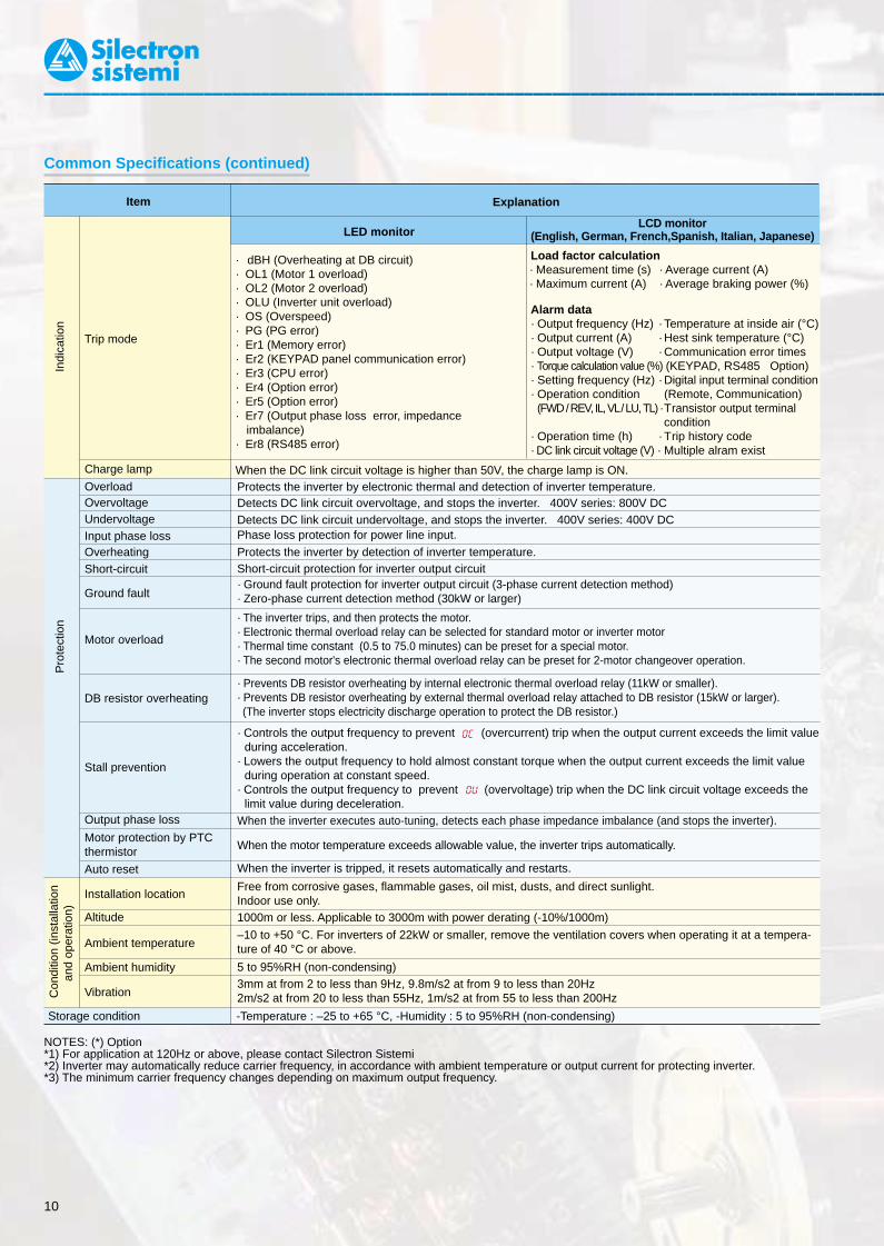
NOTES: (*) Option*1) For application at 120Hz or above, please contact Silectron Sistemi*2) Inverter may automatically reduce carrier frequency, in accordance with ambient temperature or output current for protecting inverter.*3) The minimum carrier frequency changes depending on maximum output frequency.
Load factor calculation· Measurement time (s) · Average current (A)· Maximum current (A) · Average braking power (%)
Alarm data· Output frequency (Hz) · Temperature at inside air (°C)· Output current (A) · Hest sink temperature (°C)· Output voltage (V) · Communication error times· Torque calculation value (%) (KEYPAD, RS485 Option)· Setting frequency (Hz) · Digital input terminal condition· Operation condition (Remote, Communication)
(FWD / REV, IL, VL / LU, TL) ·Transistor output terminal condition
· Operation time (h) · Trip history code· DC link circuit voltage (V) · Multiple alram exist
5 to 95%RH (non-condensing)
GVX200010 11
Item Explanation
Pro
tect
ion
· dBH (Overheating at DB circuit)· OL1 (Motor 1 overload)· OL2 (Motor 2 overload)· OLU (Inverter unit overload)· OS (Overspeed)· PG (PG error)· Er1 (Memory error)· Er2 (KEYPAD panel communication error)· Er3 (CPU error)· Er4 (Option error)· Er5 (Option error)· Er7 (Output phase loss error, impedance
imbalance)· Er8 (RS485 error)
Charge lamp When the DC link circuit voltage is higher than 50V, the charge lamp is ON.
Con
ditio
n (in
stal
latio
nan
d op
erat
ion)
OverloadOvervoltageUndervoltageInput phase lossOverheatingShort-circuit
Ground fault
Motor overload
DB resistor overheating
Stall prevention
Output phase loss
Motor protection by PTCthermistor
Auto reset
Installation location
Altitude
Ambient temperature
Ambient humidity
Vibration
Storage condition -Temperature : –25 to +65 °C, -Humidity : 5 to 95%RH (non-condensing)
Protects the inverter by electronic thermal and detection of inverter temperature.Detects DC link circuit overvoltage, and stops the inverter. 400V series: 800V DCDetects DC link circuit undervoltage, and stops the inverter. 400V series: 400V DCPhase loss protection for power line input.
Protects the inverter by detection of inverter temperature.Short-circuit protection for inverter output circuit· Ground fault protection for inverter output circuit (3-phase current detection method)· Zero-phase current detection method (30kW or larger)
· The inverter trips, and then protects the motor.· Electronic thermal overload relay can be selected for standard motor or inverter motor· Thermal time constant (0.5 to 75.0 minutes) can be preset for a special motor.· The second motor's electronic thermal overload relay can be preset for 2-motor changeover operation.
· Prevents DB resistor overheating by internal electronic thermal overload relay (11kW or smaller).· Prevents DB resistor overheating by external thermal overload relay attached to DB resistor (15kW or larger).(The inverter stops electricity discharge operation to protect the DB resistor.)
· Controls the output frequency to prevent (overcurrent) trip when the output current exceeds the limit valueduring acceleration.
· Lowers the output frequency to hold almost constant torque when the output current exceeds the limit value during operation at constant speed.
· Controls the output frequency to prevent (overvoltage) trip when the DC link circuit voltage exceeds the limit value during deceleration.
When the inverter executes auto-tuning, detects each phase impedance imbalance (and stops the inverter).
When the motor temperature exceeds allowable value, the inverter trips automatically.
When the inverter is tripped, it resets automatically and restarts.
Free from corrosive gases, flammable gases, oil mist, dusts, and direct sunlight.Indoor use only.1000m or less. Applicable to 3000m with power derating (-10%/1000m)
–10 to +50 °C. For inverters of 22kW or smaller, remove the ventilation covers when operating it at a tempera-ture of 40 °C or above.
3mm at from 2 to less than 9Hz, 9.8m/s2 at from 9 to less than 20Hz2m/s2 at from 20 to less than 55Hz, 1m/s2 at from 55 to less than 200Hz
Symbol
LED monitorLCD monitor
(English, German, French,Spanish, Italian, Japanese)
L1/R, L2/SPower input Connect a 3-phase power supply.
L3/TU, V, W Inverter output Connect a 3-phase induction motor.
P1, P(+) For DC reactorConnect the DC reactor for power-factor correcting
DC reactor: optionor harmonic current reducing.
P(+), N(-) For braking unit· Connect the braking unit (option).
Braking unit (option): 11kW or larger· Used for DC bus connection system.
P(+), DBFor external
Connect the external braking resistor (option) Only for 11kW or smallerbraking resistor
G Grounding Ground terminal for inverter chassis (housing).
R0, T0Auxiliary control Connect the same AC power supply as that of the main
1,1kW or smaller: Not correspondpower supply circuit to back up the control circuit power supply.
13Potentiometer +10V DC power supply for frequency setting POT
Allowable maximum output current : 10mApower supply (POT: 1 to 5kΩ)
12
Voltage input
· 0 to +10V DC/0 to 100% (0 to +5V DC/0 to 100%)· Reversible operation can be selected by function setting. · Input impedance: 22kΩ
0 to ±10V DC /0 to ±100% (0 to ±5V DC/0 to ±100%) · Allowable maximum input voltage: ±15V DC F01,C30· Inverse mode operation can be selected by function · If input voltage is 10 to 15V DC, the
setting or digital input signal. inverter estimate it to10V DC. +10 to 0V DC/0 to 100% (Torque control) Used for torque control reference signal. H18
(PID control) Used for PID control reference signal or feedback signal. F01, H21 (PG feedback) Used for reference signal of PG feedback control (option)
· 4 to 20mA DC/0 to 100% · Input impedance:250kΩ
Current input· Inverse mode operation can be selected by function · Allowable maximum input current: 30mA DC
setting or digital input signal. · If input current is 20 to 30mA DC , the C1 20 to 4mA DC/0 to 100% inverter estimates it to20mA DC.
Mai
nci
rcui
tA
nalo
gin
put
Dig
ital
inpu
t
Terminal name Function RemarksFun.cod.
TERMINAL FUNCTIONS
Trip mode
Indi
catio
n
Terminal Functions
(PID control) Used for PID control reference signal or feedback signal. F01, H21
(PTC-Thermistor Input)The PTC-thermistor (for motor protection) can be Change over the Pin switch on control H26,
connected to terminal C1 - 11. board. (SW2 : PTC) H27V2 Voltage input 2 0 to +10V DC Can't change over the terminal C1. F0111 Common Common for analog signal Isolated from terminal CMY and CM.
FWDForward operation FWD: ON ..... The motor runs in the forward direction. command FWD: OFF ..... The motor decelerates and stops. When FWD and REV are simultaneously
F02REV
Reverse operation REV: ON ..... The motor runs in the reverse direction. ON, the motor decelerates and stops.command REV: OFF ..... The motor decelerates and stops.
X1 Digital input 1 X2 Digital input 2
· OFF state maximum input voltage: 2V
X3 Digital input 3 (maximum source current : 5mA)X4 Digital input 4
· ON state maximum terminal E01 to
X5 Digital input 5 These terminals can be preset as follows. voltage: 22 to 27V
E09X6 Digital input 6
(allowable maximum leakage
X7 Digital input 7 current: 0.5mA).X8 Digital input 8
X9 Digital input 9(SS1) (SS1) : 2 (0, 1) different freq. are selectable.(SS2) Multistep freq. (SS1,SS2) : 4 (0 to 3) different freq. are selectable. Frequency 0 is set by F01 (or C30). C05 to(SS4) selection (SS1,SS2,SS4) : 8 (0 to 7) different freq. are selectable. (All signals of SS1 to SS8 are OFF) C19(SS8) (SS1,SS2,SS4,SS8) :16 (0 to 15) different freq. are selectable.
(RT1) ACC / DEC time (RT1) : 2 (0, 1) different ACC / DEC times are selectable. Time 0 is set by F07/F08.F07, F08
(RT2) selection (RT1,RT2) : 4 (0 to 3) different ACC / DEC times are selectable (All signals of RT1 to RT2 are OFF)E10 to E15
3-wire operationUsed for 3-wire operation.
(HLD)stop command
(HLD): ON ..... The inverter self-holds FWD or REV signal. Assigned to terminal X7 at factory setting.(HLD): OFF ..... The inverter releases self-holding.
Common Specifications (continued)
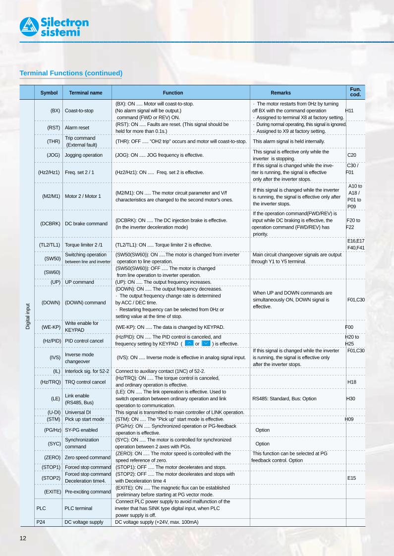
GVX200013
(BX): ON ..... Motor will coast-to-stop. · The motor restarts from 0Hz by turning (BX) Coast-to-stop (No alarm signal will be output.) off BX with the command operation H11
command (FWD or REV) ON. · Assigned to terminal X8 at factory setting.
(RST) Alarm reset(RST): ON ..... Faults are reset. (This signal should be · During normal operating, this signal is ignored.held for more than 0.1s.) · Assigned to X9 at factory setting.
(THR)Trip command
(THR): OFF ..... "OH2 trip" occurs and motor will coast-to-stop. This alarm signal is held internally. (External fault)
(JOG) Jogging operation (JOG): ON ..... JOG frequency is effective.This signal is effective only while the
C20inverter is stopping.
If this signal is changed while the inve- C30 / (Hz2/Hz1) Freq. set 2 / 1 (Hz2/Hz1): ON ..... Freq. set 2 is effective. rter is running, the signal is effective F01
only after the inverter stops.
If this signal is changed while the inverter A10 to
(M2/M1) Motor 2 / Motor 1
(M2/M1): ON ..... The motor circuit parameter and V/fis running, the signal is effective only after
A18 /characteristics are changed to the second motor's ones.
the inverter stops.P01 to P09
If the operation command(FWD/REV) is
(DCBRK) DC brake command(DCBRK): ON ..... The DC injection brake is effective. input while DC braking is effective, the F20 to(In the inverter deceleration mode) operation command (FWD/REV) has F22
priority. (TL2/TL1) Torque limiter 2 /1 (TL2/TL1): ON ..... Torque limiter 2 is effective.
E16,E17F40,F41
(SW50)
Switching operation (SW50(SW60)): ON .....The motor is changed from inverter Main circuit changeover signals are outputbetween line and inverter operation to line operation. through Y1 to Y5 terminal.
(SW60)
(SW50(SW60)): OFF ..... The motor is changed from line operation to inverter operation.
(UP) UP command (UP): ON ..... The output frequency increases.(DOWN): ON ..... The output frequency decreases.
When UP and DOWN commands are · The output frequency change rate is determined simultaneously ON, DOWN signal is F01,C30 (DOWN) (DOWN) command by ACC / DEC time.effective. · Restarting frequency can be selected from 0Hz or
setting value at the time of stop.
(WE-KP)Write enable for
(WE-KP): ON ..... The data is changed by KEYPAD. F00KEYPAD
(Hz/PID) PID control cancel(Hz/PID): ON ..... The PID control is canceled, and H20 to
frequency setting by KEYPAD ( or ) is effective. H25
Inverse mode If this signal is changed while the inverter F01,C30
(IVS)changeover
(IVS): ON ..... Inverse mode is effective in analog signal input. is running, the signal is effective onlyafter the inverter stops.
(IL) Interlock sig. for 52-2 Connect to auxiliary contact (1NC) of 52-2. (Hz/TRQ) TRQ control cancel
(Hz/TRQ): ON ..... The torque control is canceled, H18and ordinary operation is effective.
Link enable
(LE): ON ..... The link opereation is effective. Used to (LE)
(RS485, Bus)switch operation between ordinary operation and link RS485: Standard, Bus: Option H30operation to communication.
(U-DI) Universal DI This signal is transmitted to main controller of LINK operation.(STM) Pick up start mode (STM): ON ..... The "Pick up" start mode is effective. H09
(PG/Hz) SY-PG enabled(PG/Hz): ON ..... Synchronized operation or PG-feedback
Optionoperation is effective.
(SYC)Synchronization (SYC): ON ..... The motor is controlled for synchronized
Optioncommand operation between 2 axes with PGs.
(ZERO) Zero speed command(ZERO): ON ..... The motor speed is controlled with the This function can be selected at PG speed reference of zero. feedback control. Option
(STOP1) Forced stop command (STOP1): OFF ..... The motor decelerates and stops.
(STOP2)Forced stop command (STOP2): OFF ..... The motor decelerates and stops with
E15Deceleration time4. with Deceleration time 4
(EXITE) Pre-exciting command(EXITE): ON ..... The magnetic flux can be established
preliminary before starting at PG vector mode.Connect PLC power supply to avoid malfunction of the
PLC PLC terminal inveter that has SINK type digital input, when PLCpower supply is off.
P24 DC voltage supply DC voltage supply (+24V, max. 100mA)
Symbol Terminal name Function Remarks
Terminal name Function Remarks
Output voltage (0 to 10V DC) is proportional to selectedfunction’s value as follows.The proportional coefficient and bias value can be preset.· Output frequency 1
(Before slip compensation) (0 to max. frequency)· Output frequency 2
(After slip compensation) (0 to max. frequency)· Output current (0 to 200%)· Output voltage (0 to 200%) · Output torque (0 to 200%)· Load factor (0 to 200%)· Input power (0 to 200%)· PID feedback value (0 to 100%)· PG feedback value (0 to max. speed)· DC link circuit voltage (0 to 1000V)· Universal AO (0 to 100%)· Pulse rate mode : Pulse rate is proportional to selected
function’s value* (50% duty pulse)· Average voltage mode : Average voltage is proportional to
selected function’s value* (2670p/s pulse width control)
· Kinds of function to be output is same as those of analog output (FMA).
Common for pulse output
Output the selected signals from the following items.
Outputs ON signal when the output frequency is higher thanstarting frequency.Outputs ON signal when the difference between output frequencyand setting frequency is smaller than FAR hysteresis width.Outputs ON signal by comparison of output frequency andpreset value (level and hysteresis).Outputs ON signal when the inverter stops by undervoltagewhile the operation command is ON.Outputs ON signal in braking or stopping mode, and OFFsignal in driving mode.Outputs ON signal when the inverter is in torque-limitingmode.Outputs ON signal during auto restart operation (Instantaneouspower failure) mode. (including "restart time")· Outputs ON signal when the electronic thermal value is
higher than preset alarm level.· Outputs ON signal when the output current value is higher
than preset alarm level.Outputs ON signal when the inverter is in KEYPAD operationmode.Outputs ON signal when the inverter is in stopping mode or inDC braking mode.Outputs ON signal when the inverter is ready for operation.
Outputs 88's ON signal for Line/Inverter changeover operation.
Outputs 52-2’s ON signal for Line/Inverter changeover operation.
Outputs 52-1’s ON signal for Line/Inverter changeover operation.
Outputs the motor changeover switch ON signal from motor 1to motor 2.
FMA Analog monitor
(11) (Common)
FMP Pulse rate monitor
(CM) (Common)
CM CommonY1 Transistor output 1Y2 Transistor output 2Y3 Transistor output 3Y4 Transistor output 4
(RUN) Inverter running
(FAR)
Frequency equi-valence signal
(FDT1)
Frequency level detection
(LU)
Undervoltage detection signal
(B/D) Torque polarity
(TL) Torque limiting
(IPF) Auto-restarting
(OL1)Overload earlywarning
(KP)
KEYPAD operation mode
(STP) Inverter stopping
(RDY) Ready output (SW88)
Line/Inverter changeover for 88)
(SW52-2)Line/Inv changeover(for 52-1)
(SW52-1)Line/Inv changeover(for 52-1)
(SWM2) Motor2/Motor1
Allowable maximum output current: 2mA F30 to F31
Allowable maximum output current : 2mAF33 toF35
Isolated from terminal CMY and 11.· OFF state maximum output voltage : 3V
(Allowable maximum sink current : 50mA) E20 to· ON state maximum leakage current : 0.1mA E23
(Allowable maximum voltage : 27V)
E30
E31, E32
E33 to E35
F02
A01 to A18
12
Symbol
Ana
log
outp
utP
ulse
out
put
Tran
sist
or o
utpu
t
Dig
ital i
nput
Fun.cod.
Fun.cod.
Terminal Functions (continued)

Terminal name Function Remarks
Used for auxiliary circuit of 52-1.(Same function as AX1, AX2 terminal by FRENIC5000G9Sseries. (30kW or larger))Outputs time up signal (100ms ON pulse) at every stage endof PATTERN operation.Outputs one cycle completion signal (100ms ON pulse) atPATTERN operation.
Outputs PATTERN operation’s stage No. by signals STG1,STG2 and STG4.
Outputs trip alarm No. by signals AL1, AL2, AL4, and AL8.
Outputs the inverter cooling fan operation status signal.Outputs ON signal at auto resetting mode. (Including "Resetinterval")Outputs command signal from main controller of LINKoperation.Outputs ON signal when the heat sink temperature is higherthan (trip level – 10°C), and outputs OFF signal when thetemperature is lower than (trip level – 15°C).
Synchronization completion signal for synchronized operation.
Outputs ON signal when the calculated lifetime is longer thanpreset alarm level.2nd-outputs ON signal by comparison of output frequency andpreset value (FDT2 level).2nd-outputs ON signal when the output current value is largerthan preset alarm level (OL2 level).
Outputs ON signal when the C1 current is smaller than 2mA.
Outputs ON signal when motor speed is larger than stopspeed* on vector control with PG.
Common for transistor output signal.
Outputs a contact signal when a protective function isactivated.Changeable exciting mode active or non-exciting mode activeby function "F36".Funcntions can be selected the same as Y1 to Y4.Changeable exciting mode active or non-exciting mode activeby function "E25".
Connect the RS485 link signal.
(AX)Auxiliary terminal
(for 52-1)
(TU) Time-up signal
(TO)Cycle completion signal
(STG1)Stage No. indication 1
(STG2)Stage No. indication 2
(STG4)Stage No. indication 4
(AL1) Alarm indication 1(AL2) Alarm indication 2(AL4) Alarm indication 4(AL8) Alarm indication 8(FAN) Fan operation signal
(TRY) Auto-resetting
(U-DO) Universal DO
(OH)Overheat early warning
(SY)Synchronizationcompletion signal
(LIFE) Lifetime alarm
(FDT2)2nd Freq. leveldetection
(OL2)2nd OL level earlywarning
(C1OFF)Terminal C1 off signal
(N-EX)Speed existence signal
CMYCommon (transistor output)
30A, 30B, Alarm relay output30C,
Y5A, Y5C Relay output
DX+, DX-, RS485 I/O terminal
SD
Refer to wiring diagram example.
C21 to C28
H06H04, H05
Option
* stop speed = stop frequency (F25)F25
120/pole [r/m]
Isolated from teminals CM and 11.
· Contact rating : 250V AC, 0.3A, cosΦ=0.3 48V DC, 0.5A, non-inductive
NOTE:Common terminals [11], (CM),and <CMY> for control circuitsare
*1) Use the inverter whose rated inputvoltage matches the power supplyvoltage.
*2)Use this peripheral device when necessary.*3)75kW or smaller:
Terminals [P1] and [P(+)] are connectedwith a jumper wire before shipping. Whenconnecting an optional DC reactor (DCR)*6),remove the jumper wire that connects theterminals [P1] and [P(+)].
*4)For models from 0.55 to 11kW, a built-inbraking resistor (DBR) is connected to theinverter before shipping. (DBR is not mountedon models 15kW or larger.)
*5)Terminals [R0] and [T0] are provided formodels 2,2kW or larger. These terminals arenot provided for models 1,1kW or smaller.Even if these terminals are not powered, theinverter can be operated.
*6)Digital input common switching:Source (P24 terminal)Sink (CM terminal).
The following diagram is for reference only. For detailed wiring diagrams, refer to the relevant instruction manual.
BASIC WIRING DIAGRAM
L1/R
L2/S
L3/T
U
V
WG
GG
M
N(-) N(-)
N(-)
P(+) DBRDBP(+)
P1
(R0)
(T0)
X9
CM
FMP
(DX-) (DX+) (SD)
X1
PLC
P24
FWD
REVCM
X8
Y5C
Y5A
Y4
Y1
Y2
Y3
CMY
X7
X6
X5
X4
X3X2
0V 30A
30B
30C
30
0V
+DC10V
+DC24V+DC 0~10V
13
12
11
C1
FMA
P(+)P1
P1
MCCB or ELCB ( *2)
Power supply(*1) 3-phase380 to 480V50/60Hz
Main circuit
Jumper wire
(*3) (*6)
(*4)
(*3)
Auxiliary control power supply( *5)
Grounding Grounding
Control circuit
Analog input
Potentiometer power supply
Voltageinput
Voltage input 2
Current input
Digital input
Pulse output(frequency monitor)
*OptionRS485 interface port
Pulse output
Motor*
DC reactor (DCR)
Alarm output (for anyfault)
Relayoutput
Transistoroutput
11 kW or smaller
CNUX ( )U1 U2
V2
14
Symbol
Tran
sist
or o
utpu
tR
elay
out
put
LIN
K
GVX2000
Fun.cod.
Source
Sink
Keypad panel Operation
Terminal Arrangement
15
G
G
L1/R L2/S L3/T DB P1 P(+) N(-) U V W
30C
30B
Y5C
Y4
Y2
11
12
13
V2
CM
CM
FWD
REV
P24
P24
DXB
DXA
SD
Y3
Y1
C1
FMA
FMP
PLC
X1
X2
X3
X4
X5
X6
X7
X8
X9
30A
Y5A
CMY
F36
E24
E25
(*6)
Terminal Functions (continued)
• Main circuit terminals
• Control circuit terminals
(Up to 11kW)

GVX2000
RUNRUN
GVX2000
1716
The following diagram is for reference only. For detailed wiring diagrams, refer to the relevant instruction manual.
*1)Use the inverter whose rated input voltage matches the powersupply voltage.
*2)An optional device. Use it when necessary.*3)Use this peripheral device when necessary.*4)Terminals [P1] and [P(+)] are connected with a jumper wire before shipping. When connecting an optional DC reactor (DCR)
*9), remove the jumper wire that connects the terminals [P1] and[P(+)].
*5)For models from 0.2 to 11kW, a built-in braking resistor (DBR) isconnected to the inverter before shipping. (DBR is not mounted onmodels 15kW or larger.) When connecting an optional externalbraking resistor (DB), remove the DBR connection cables from[P(+)] and [DB] terminals. The end of the removed cables (indicatedwith an X) must be insulated.
*6)When connecting an optional external braking resistor (DB), besure to also use an optional braking unit *8). Connect the optionalbraking unit to the [P(+)] and [N(-)] terminals. Auxiliary terminals[1] and [2] have polarity.Be sure to connect cables to these terminals correctly. (See thediagram)
*7)Terminals [R0] and [T0] are provided for models 2.2kW or larger.These terminals are not provided for models 1.1kW or smaller.Even if these terminals are not powered, the inverter can beoperated.
*8)Digital input common switching:Source (P24 terminal)Sink (CM terminal).
( + )( - )
( + )( 0V )
L1/R
L2/S
L3/T
U
V
WG
GG
M
N(-)P(+)P1
(R0)
(T0)
X9CM
FMP
(DX-) (DX+) (SD)
X1
PLC
FWD
REV
CM
X8
X7
X6
X5
X4
X3X2
0V
30A
30B
30C
30
0V
+DC10V
+DC24V+DC0~10V
13
12
11
C1
V2
FMA
15 kW or larger
MCCB or ELCB ( *3) Power supply ( *1)
3-phase400 to 480V
50/60Hz
Main circuit
(*5)
Grounding Grounding
Control circuit
RS485 interface port
Pulse output
Motor*
Alarm output (for any fault)
Relay output
Transistoroutput
60Hz
1
2
3
Auxiliary control power supply ( *7)
DC reactor (DCR) (*2) ( *9)
External braking resistor (DB) (*2) (*6)
External braking resistor (DB) (*2) (*6)
Braking unit ( *2) ( *8)
GDB
DB N(-)
DBR
(THR)
(THR)
P24P
P(+)
G
G
N
DBP
P
P
DB
(*4)
11 kW or smaller
Y5C
Y5A
Y4
Y1
Y2
Y3
CMY
P24
*Option
x x
KEYPAD PANEL FUNCTIONS AND OPERATIONS
LCD monitorIn operation mode :Displays various items of informationsuch as operation condition andfunction data. Operation guidance,which can be scrolled, is displayed atthe bottom.In program mode :Displays functions and data.
Up/Down keysIn operation mode :Increases or decreases thefrequency or speed.In program mode :Increases or decreasesfunction code number anddata set value.
Reset keyIn program mode :Cancels the current inputdata and shifts the screen.In trip mode :Releases the trip-stop state.
LED monitorIn operation mode:Displays the setting frequency,output current, voltage, motorspeed, or line speed.In trip mode:Displays code indicating thecause of trip.
Unit indicationDisplays the unit for theinformation shown on theLED monitor.
FWD/REV keysIn operation mode :Starts the inverter with forward orreverse operation command.Pressing the FWD or REV key lightsthe RUN lamp.Invalid when the function code F02(Operation method) is set at 1(External signaloperation).
Stop keyIn operation mode :Stops the inverter.Invalid when the function codeF02 (Operation method) is setat 1 (External signaloperation).
Function/Data Select keyIn operation mode :Changes the displayed valuesof LED monitor.In program mode :Selects the function code or store thedata.
Shift key (Column shift)In program mode :Moves the cursor horizontallyat data change. Pressing thiskey with the UP or DOWNkey, the screen changes tothe next function block.
Program keySwitches the display to amenu screen or to the initialscreen for operation mode oralarm mode.
NOTE:Common terminals [11], (CM), and <CMY>for control circuits are isolated from oneanother.
Source
Sink
Analog input
Potentiometer power supply
Voltageinput
Voltage input 2
Current input
Digital input
Pulse output(frequency monitor)
P24
Keypad panel
External signal input Operation
(*8)

GVX2000
RUNRUN
GVX2000
1716
The following diagram is for reference only. For detailed wiring diagrams, refer to the relevant instruction manual.
*1)Use the inverter whose rated input voltage matches the powersupply voltage.
*2)An optional device. Use it when necessary.*3)Use this peripheral device when necessary.*4)Terminals [P1] and [P(+)] are connected with a jumper wire before shipping. When connecting an optional DC reactor (DCR)
*9), remove the jumper wire that connects the terminals [P1] and[P(+)].
*5)For models from 0.2 to 11kW, a built-in braking resistor (DBR) isconnected to the inverter before shipping. (DBR is not mounted onmodels 15kW or larger.) When connecting an optional externalbraking resistor (DB), remove the DBR connection cables from[P(+)] and [DB] terminals. The end of the removed cables (indicatedwith an X) must be insulated.
*6)When connecting an optional external braking resistor (DB), besure to also use an optional braking unit *8). Connect the optionalbraking unit to the [P(+)] and [N(-)] terminals. Auxiliary terminals[1] and [2] have polarity.Be sure to connect cables to these terminals correctly. (See thediagram)
*7)Terminals [R0] and [T0] are provided for models 2.2kW or larger.These terminals are not provided for models 1.1kW or smaller.Even if these terminals are not powered, the inverter can beoperated.
*8)Digital input common switching:Source (P24 terminal)Sink (CM terminal).
( + )( - )
( + )( 0V )
L1/R
L2/S
L3/T
U
V
WG
GG
M
N(-)P(+)P1
(R0)
(T0)
X9CM
FMP
(DX-) (DX+) (SD)
X1
PLC
FWD
REV
CM
X8
X7
X6
X5
X4
X3X2
0V
30A
30B
30C
30
0V
+DC10V
+DC24V+DC0~10V
13
12
11
C1
V2
FMA
15 kW or larger
MCCB or ELCB ( *3) Power supply ( *1)
3-phase400 to 480V
50/60Hz
Main circuit
(*5)
Grounding Grounding
Control circuit
RS485 interface port
Pulse output
Motor*
Alarm output (for any fault)
Relay output
Transistoroutput
60Hz
1
2
3
Auxiliary control power supply ( *7)
DC reactor (DCR) (*2) ( *9)
External braking resistor (DB) (*2) (*6)
External braking resistor (DB) (*2) (*6)
Braking unit ( *2) ( *8)
GDB
DB N(-)
DBR
(THR)
(THR)
P24P
P(+)
G
G
N
DBP
P
P
DB
(*4)
11 kW or smaller
Y5C
Y5A
Y4
Y1
Y2
Y3
CMY
P24
*Option
x x
KEYPAD PANEL FUNCTIONS AND OPERATIONS
LCD monitorIn operation mode :Displays various items of informationsuch as operation condition andfunction data. Operation guidance,which can be scrolled, is displayed atthe bottom.In program mode :Displays functions and data.
Up/Down keysIn operation mode :Increases or decreases thefrequency or speed.In program mode :Increases or decreasesfunction code number anddata set value.
Reset keyIn program mode :Cancels the current inputdata and shifts the screen.In trip mode :Releases the trip-stop state.
LED monitorIn operation mode:Displays the setting frequency,output current, voltage, motorspeed, or line speed.In trip mode:Displays code indicating thecause of trip.
Unit indicationDisplays the unit for theinformation shown on theLED monitor.
FWD/REV keysIn operation mode :Starts the inverter with forward orreverse operation command.Pressing the FWD or REV key lightsthe RUN lamp.Invalid when the function code F02(Operation method) is set at 1(External signaloperation).
Stop keyIn operation mode :Stops the inverter.Invalid when the function codeF02 (Operation method) is setat 1 (External signaloperation).
Function/Data Select keyIn operation mode :Changes the displayed valuesof LED monitor.In program mode :Selects the function code or store thedata.
Shift key (Column shift)In program mode :Moves the cursor horizontallyat data change. Pressing thiskey with the UP or DOWNkey, the screen changes tothe next function block.
Program keySwitches the display to amenu screen or to the initialscreen for operation mode oralarm mode.
NOTE:Common terminals [11], (CM), and <CMY>for control circuits are isolated from oneanother.
Source
Sink
Analog input
Potentiometer power supply
Voltageinput
Voltage input 2
Current input
Digital input
Pulse output(frequency monitor)
P24
Keypad panel
External signal input Operation
(*8)