Embed Size (px)
Citation preview

INNOVATIONS CATALOGUE
2016
A4
L V i A004 A005 KMT I i 2016 B d E l i P d B h 004 005 EN A 32015651AM
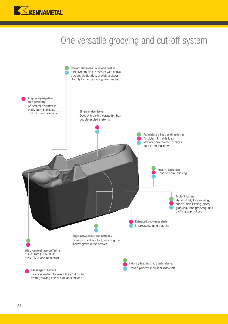
Coolant channel on rake and pocket
Proprietary negative
chip geometry
First system on the market with active
coolant distribution, providing coolant
directly to the minor edge and radius.
Added chip control in
steel, cast, stainless,
and hardened materials.
Enhanced body edge design
Improved seating stability.
Proprietary V back seating design
Provides high side load
stability comparable to longer
double-ended inserts.
Angle between top and bottom V
Creates a pull-in effect, securing the
insert tighter in the pocket.
Industry-leading grade technologies
Proven performance in all materials.
1,4–10mm (.055–.394")
PVD, CVD, and uncoated.
Wide range of insert offering
Use one system to select the right tooling
for all grooving and cut-off applications.
Full range of holders
Single-ended design
Deeper grooving capability than
double-ended systems.
Triple-V feature
High stability for grooving,
cut-off, side turning, deep
grooving, face grooving, and
profiling applications.
Positive back stopEnables easy indexing.
One versatile grooving and cut-off system
A004_A005_KMT_Innovations_2016_Beyond_Evolution_Product_Brochure_004_005_EN_me.indd 4 8/3/15 8:14 AM
A5
L V i A004 A005 KMT I i 2016 B d E l i P d B h 004 005 EN A 32015651AM
If you are a Various Component Producer
Challenge
• Reduce setup time.
• Selecting the right tool for the job.
• Using fewer tools to complete the job.
• Reduce tooling inventory.
Solution
• Versatility:
– Holders, inserts, chipbreakers, and grades.
– Same pocket for many operations.
• Choose from one system.
• Indexability.
that reduces inventory.
If you are a High Volume Production Shop
Challenge
• Increase machine uptime.
• Reduce setup time.
• Lower cost per part.
• Freeing up production capacity.
Solution
• Functional stability.
• Grade, chip control, coolant —
MRR and automation.
• Clean and consistent cutting tool edge.
• Indexability.
• Versatility — more operations with
the same pocket.
If Workpiece Finish and Accuracy is most important to you
Challenge
• Better surface finish.
• Tool consistency.
• Machining accuracy.
• Selecting the right tool.
Solution
• Functional stability — Triple V clamping
and three-point contact.
• Process stability — chipbreaker, grade, and coolant.
• Easy to index — clamping and positive back stop.
• Easy to choose from one system — full range
of widths and holder styles, chipbreakers,
grades, and radii.
One system capable of all
grooving and cut-off applications —
A004_A005_KMT_Innovations_2016_Beyond_Evolution_Product_Brochure_004_005_EN_me.indd 5 8/3/15 8:14 AM
A6
L V i A006 A007 KMT I i 2016 B d E l i P d B h 006 007 EN J l 282015111PM
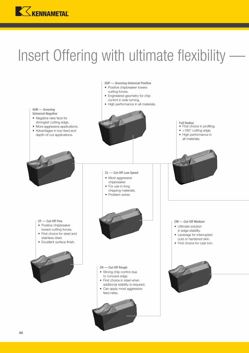
Insert Offering with ultimate flexibility —
CL — Cut-Off Low Speed
• Most aggressive
chipbreaker.
• For use in long
chipping materials.
• Problem solver.
GUN — Grooving
Universal Negative
• Negative rake face for
strongest cutting edge.
• More aggressive applications.
• Advantages in low-feed and
depth-of-cut applications.
GUP — Grooving Universal Positive
• Positive chipbreaker lowers
cutting forces.
• Engineered geometry for chip
control in side turning.
• High performance in all materials.
CM — Cut-Off Medium
• Ultimate solution
in edge stability.
• Leverage for interrupted
cuts or hardened skin.
• First choice for cast iron.
CR — Cut-Off Rough
• Strong chip control due
to concave edge.
• First choice in steel when
additional stability is required.
• Can apply most aggressive
feed rates.
Full Radius• First choice in profiling.
• >180° cutting edge.
• High performance in
all materials.
CF — Cut-Off Fine
• Positive chipbreaker
lowers cutting forces.
• First choice for steel and
stainless steel.
• Excellent surface finish.
A006_A007_KMT_Innovations_2016_Beyond_Evolution_Product_Brochure_006_007_EN_me.indd 6 7/28/15 1:15 PM
A7
L V i A006 A007 KMT I i 2016 B d E l i P d B h 006 007 EN J l282015111PM
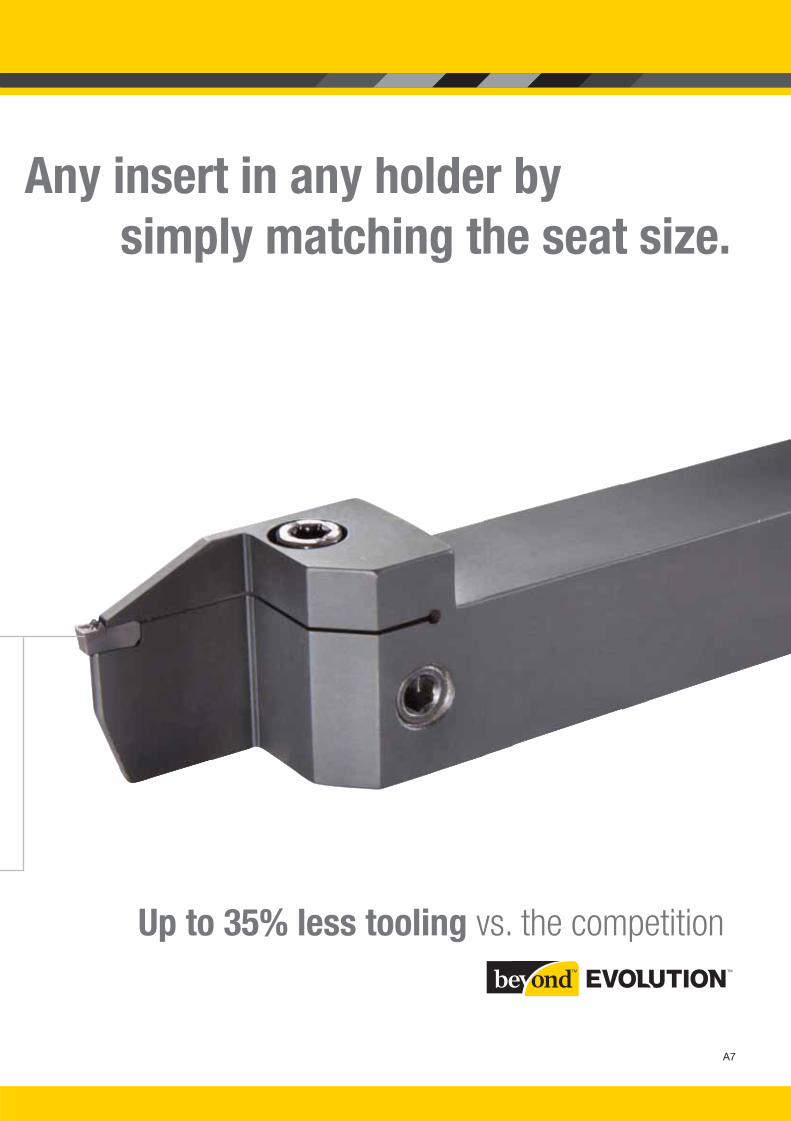
Any insert in any holder by
simply matching the seat size.
Up to 35% less tooling vs. the competition
A006_A007_KMT_Innovations_2016_Beyond_Evolution_Product_Brochure_006_007_EN_me.indd 7 7/28/15 1:15 PM
A8
L V i A008 A009 KMT I i 2016 B d E l i P d B h 008 009 EN J l 282015111PM
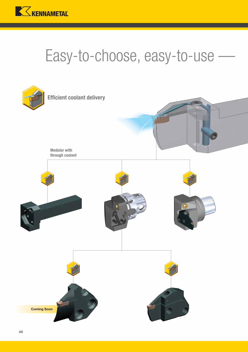
Easy-to-choose, easy-to-use —
Modular with
through coolant
Coming Soon
Efficient coolant delivery
A008_A009_KMT_Innovations_2016_Beyond_Evolution_Product_Brochure_008_009_EN_me.indd 8 7/28/15 1:15 PM
A9
L V i A008 A009 KMT I i 2016 B d E l i P d B h 008 009 EN J l282015111PM
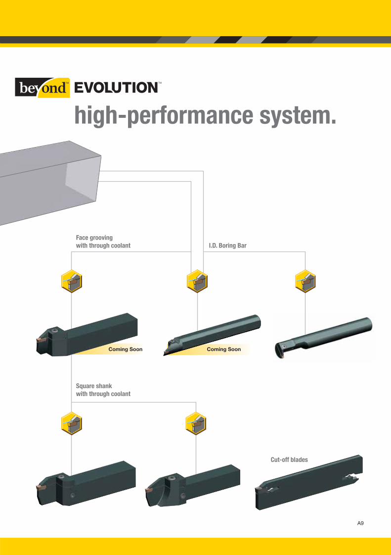
Square shank
with through coolant
I.D. Boring Bar
Coming SoonComing Soon
Face grooving
with through coolant
Cut-off blades
high-performance system.
A008_A009_KMT_Innovations_2016_Beyond_Evolution_Product_Brochure_008_009_EN_me.indd 9 7/28/15 1:15 PM
A10
L V i A010 A011 KMT I i 2016 B d E l i P d B h 010 011 EN J l 1720151223PM
Beyond™ Evolution™
Grades and Grade Descriptions
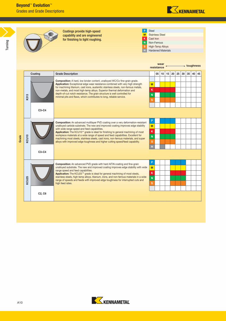
Coatings provide high-speed
capability and are engineered
for finishing to light roughing.
P Steel
M Stainless Steel
K Cast Iron
N Non-Ferrous
S High-Temp Alloys
H Hardened Materials
wear
resistancetoughness
Coating Grade Description 05 10 15 20 25 30 35 40 45
Gra
de
K313
Composition: A hard, low binder content, unalloyed WC/Co fine-grain grade.
Application: Exceptional edge wear resistance combined with very high strength
for machining titanium, cast irons, austenitic stainless steels, non-ferrous metals,
non-metals, and most high-temp alloys. Superior thermal deformation and
depth-of-cut notch resistance. The grain structure is well controlled for
minimal pits and flaws, which contributes to long, reliable service.
M
K
N
S
C3–C4
KC
U10
Composition: An advanced multilayer PVD coating over a very deformation-resistant
unalloyed carbide substrate. The new and improved coating improves edge stability
with wide range speed and feed capabilities.
Application: The KCU10™ grade is ideal for finishing to general machining of most
workpiece materials at a wide range of speed and feed capabilities. Excellent for
machining most steels, stainless steels, cast irons, non-ferrous materials, and super
alloys with improved edge toughness and higher cutting speed/feed capability.
P
M
K
N
S
C3–C4
H
KC
U25
Composition: An advanced PVD grade with hard AlTiN coating and fine-grain
unalloyed substrate. The new and improved coating improves edge stability with wide
range speed and feed capabilities.
Application: The KCU25™ grade is ideal for general machining of most steels,
stainless steels, high-temp alloys, titanium, irons, and non-ferrous materials in a wide
range of speeds and feeds with improved edge toughness for interrupted cuts and
high feed rates.
P
M
K
N
S
C2, C6
Turn
ing
A010_A011_KMT_Innovations_2016_Beyond_Evolution_Product_Brochure_010_011_EN_me.indd 10 7/28/15 1:16 PM
A11
L V i A010 A011 KMT I i 2016 B d E l i P d B h 010 011 EN J l1720151223PM
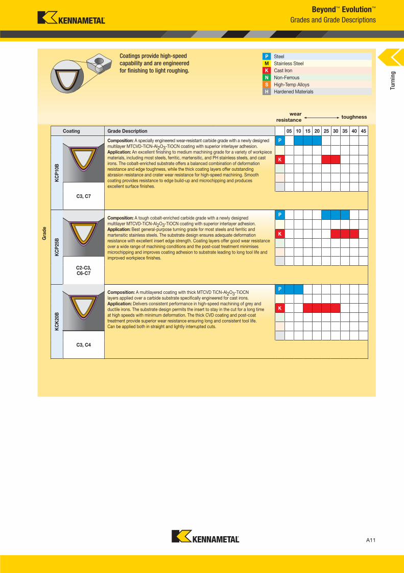
KC
P10B
Composition: A specially engineered wear-resistant carbide grade with a newly designed
multilayer MTCVD-TiCN-Al2O3-TiOCN coating with superior interlayer adhesion.
Application: An excellent finishing to medium machining grade for a variety of workpiece
materials, including most steels, ferritic, martensitic, and PH stainless steels, and cast
irons. The cobalt-enriched substrate offers a balanced combination of deformation
resistance and edge toughness, while the thick coating layers offer outstanding
abrasion resistance and crater wear resistance for high-speed machining. Smooth
coating provides resistance to edge build-up and microchipping and produces
excellent surface finishes.
P
K
C3, C7
KC
P25B
Composition: A tough cobalt-enriched carbide grade with a newly designed
multilayer MTCVD-TiCN-Al2O3-TiOCN coating with superior interlayer adhesion.
Application: Best general-purpose turning grade for most steels and ferritic and
martensitic stainless steels. The substrate design ensures adequate deformation
resistance with excellent insert edge strength. Coating layers offer good wear resistance
over a wide range of machining conditions and the post-coat treatment minimises
microchipping and improves coating adhesion to substrate leading to long tool life and
improved workpiece finishes.
P
K
C2-C3, C6-C7
KC
K20B
Composition: A multilayered coating with thick MTCVD TiCN-Al2O3-TiOCN
layers applied over a carbide substrate specifically engineered for cast irons.
Application: Delivers consistent performance in high-speed machining of grey and
ductile irons. The substrate design permits the insert to stay in the cut for a long time
at high speeds with minimum deformation. The thick CVD coating and post-coat
treatment provide superior wear resistance ensuring long and consistent tool life.
Can be applied both in straight and lightly interrupted cuts.
P
K
C3, C4
Beyond™ Evolution™
Grades and Grade Descriptions
wear
resistancetoughness
Coating Grade Description 05 10 15 20 25 30 35 40 45
Coatings provide high-speed
capability and are engineered
for finishing to light roughing.
Gra
de
P Steel
M Stainless Steel
K Cast Iron
N Non-Ferrous
S High-Temp Alloys
H Hardened Materials
Turn
ing
A010_A011_KMT_Innovations_2016_Beyond_Evolution_Product_Brochure_010_011_EN_me.indd 11 7/28/15 1:16 PM
A12
L V i A012 A013 KMT I i 2016 B d E l i P d B h 012 013 EN J l 282015112PM
Grooving and Cut-Off
Five Easy Steps to Maximise Productivity
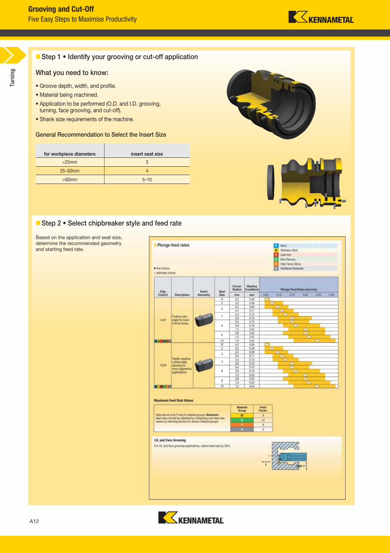
Step 1 • Identify your grooving or cut-off application
What you need to know:
• Groove depth, width, and profile.
• Material being machined.
• Application to be performed (O.D. and I.D. grooving,turning, face grooving, and cut-off).
• Shank size requirements of the machine.
for workpiece diameters insert seat size
<25mm 3
25–50mm 4
>50mm 5–10
General Recommendation to Select the Insert Size
Step 2 • Select chipbreaker style and feed rate
Based on the application and seat size,
determine the recommended geometry
and starting feed rate.
Turn
ing
A012_A013_KMT_Innovations_2016_Beyond_Evolution_Product_Brochure_012_013_EN_me.indd 12 7/28/15 1:16 PM
A13
L V i A012 A013 KMT I i 2016 B d E l i P d B h 012 013 EN J l282015112PM
Grooving and Cut-Off
Five Easy Steps to Maximise Productivity
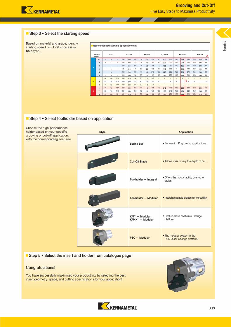
Recommended Starting Speeds [m/min]
MaterialGroup
K313 KCU10 KCU25 KCP10B KCP25B KCK20B
P
0-1 – – – 140 280 335 110 225 270 185 400 450 145 290 365 200 440 490
2 – – – 140 200 245 110 160 195 185 270 350 145 200 305 200 300 380
3 – – – 140 155 245 110 125 195 170 190 260 140 155 245 600 200 280
4 – – – 75 110 170 60 90 135 90 145 200 75 110 180 100 160 220
5 – – – 120 200 260 100 160 210 150 220 305 120 200 270 165 240 330
6 – – – 110 150 230 85 120 185 120 180 275 110 150 230 130 190 300
M
1 60 90 120 140 210 260 90 170 245 – – – – – – – – –
2 45 75 110 120 200 245 90 150 245 – – – – – – – – –
3 35 65 100 120 180 245 90 140 210 – – – – – – – – –
K
1 30 75 120 120 180 245 100 145 195 170 245 440 140 200 360 210 305 550
2 25 70 110 90 150 210 70 120 170 120 195 340 100 160 280 150 245 430
3 20 60 90 60 110 150 50 85 120 120 170 270 100 140 220 150 210 335
Step 3 • Select the starting speed
Based on material and grade, identify
starting speed (vc). First choice is in
bold type.
Choose the high-performance
holder based on your specific
grooving or cut-off application,
with the corresponding seat size.
B
A
Step 4 • Select toolholder based on application
Step 5 • Select the insert and holder from catalogue page
Congratulations!
You have successfully maximised your productivity by selecting the best insert geometry, grade, and cutting specifications for your application!
Boring Bar • For use in I.D. grooving applications.
Cut-Off Blade • Allows user to vary the depth of cut.
Toolholder — Integral• Offers the most stability over other
styles.
Toolholder — Modular • Interchangeable blades for versatility.
KM™ — ModularKM4X™ — Modular
• Best-in-class KM Quick Change platform.
PSC — Modular• The modular system in the
PSC Quick Change platform.
ApplicationStyle
Turn
ing
A012_A013_KMT_Innovations_2016_Beyond_Evolution_Product_Brochure_012_013_EN_me.indd 13 7/28/15 1:16 PM
A14
L V i A014 A015 KMT I i 2016 B d E l i P d B h 014 015 EN A 720151248PM
Grooving and Cut-Off
Beyond™ Evolution™ Grooving Inserts
n GUP Precision Molded • Inch
� fi rst choice
� alternate choice
P � � � � �
M � � �
K � � � � � �
N � � �
S � � �
H �
W W tol ± RR LI
catalog numberseat size mm in mm in mm in mm in K
CU
10
KC
U25
KC
P10B
KC
P25B
KC
K20B
K313
EG130I03U05GUP 3 3,301 .130 0,075 .003 0,20 .008 9,60 .378 � � � � – –
EG130I03U1GUP 3 3,301 .130 0,075 .003 0,40 .016 9,60 .378 � � � � – –
EG192I04U1GUP 4 4,877 .192 0,075 .003 0,40 .016 10,19 .401 � � � � – –
EG192I04U2GUP 4 4,877 .192 0,075 .003 0,79 .031 10,19 .401 � � � � – –
EG255I06U1GUP 6 6,478 .255 0,075 .003 0,40 .016 14,58 .574 � � � � – –
EG255I06U2GUP 6 6,478 .255 0,075 .003 0,80 .031 14,58 .574 � � � � – –
EG317I08U3GUP 8 8 051 317 0 075 003 1 19 047 17 46 687
Turn
ing
W W tol ± RR LI
Kennametal Grooving Inserts
Catalogue Numbering System • Grooving Inserts
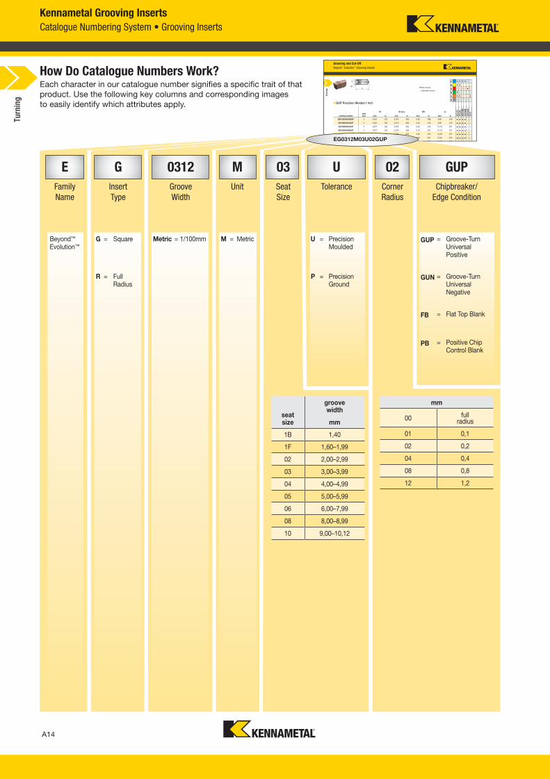
seatsize
groovewidth
mm
1B 1,40
1F 1,60–1,99
02 2,00–2,99
03 3,00–3,99
04 4,00–4,99
05 5,00–5,99
06 6,00–7,99
08 8,00–8,99
10 9,00–10,12
Each character in our catalogue number signifies a specific trait of that
product. Use the following key columns and corresponding images
to easily identify which attributes apply.
How Do Catalogue Numbers Work?
I06U1EG255I06 GUP
mm
00 fullradius
01 0,1
02 0,2
04 0,4
08 0,8
12 1,2
EG255EG
66
5555I00
33GGG
5 2GGU
6
5 0,075
1 19
6
EG0312M03U02GUP
E G 0312 M 03 U 02 GUP
Family
Name
Insert
Type
Groove
Width
Unit Seat
Size
Tolerance Corner
Radius
Chipbreaker/
Edge Condition
Beyond™ Evolution™
G = Square Metric = 1/100mm M = Metric U = Precision Moulded
GUP = Groove-Turn Universal Positive
R = Full Radius
P = Precision Ground
GUN = Groove-Turn Universal Negative
FB = Flat Top Blank
PB = Positive Chip Control Blank
Turn
ing
A014_A015_KMT_Innovations_2016_Beyond_Evolution_Product_Brochure_014_015_EN_me.indd 14 8/7/15 12:49 PM
A15
L V i A014 A015 KMT I i 2016 B d E l i P d B h 014 015 EN A 720151248PM
Grooving and Cut-Off
Beyond™ Evolution™ Cut-Off Inserts
� fi rst choice
� alternate choice
Right Hand Neutral Left Hand
Right Hand Neutral Left Hand
n CF Precision Moulded • Metric
catalogue numberseat size W W tol ± LI αR αL RR RL K
CU
10
KC
U25
KC
P10B
KC
P25B
KC
K20B
K313
EC014M1BL06CF01 1B 1,400 0,050 9,00 — 6 0,15 — – � – – – –
EC014M1BN00CF01 1B 1,400 0,050 9,00 — — 0,15 0,15 – � – – – –
EC014M1BR06CF01 1B 1,400 0,050 9,00 6 — — 0,15 – � – – – –
EC020M02L06CF02 2 2,000 0,050 8,97 — 6 0,20 — – � – – – –
P � � � � �
M � � �
K � � � � � �
N � � �
S � � �
H �
Turn
ing
Kennametal Cut-Off Inserts
Catalogue Numbering System • Cut-Off Inserts
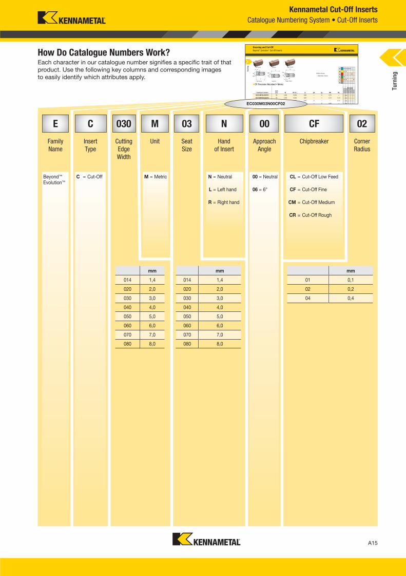
Each character in our catalogue number signifies a specific trait of that
product. Use the following key columns and corresponding images
to easily identify which attributes apply.
How Do Catalogue Numbers Work?
E C 030 M 03 N 00 CF 02
Family
Name
Insert
Type
Cutting
Edge
Width
Unit Seat
Size
Hand
of Insert
Approach
Angle
Chipbreaker Corner
Radius
Beyond™ Evolution™
C = Cut-Off M = Metric N = Neutral 00 = Neutral CL = Cut-Off Low Feed
L = Left hand 06 = 6° CF = Cut-Off Fine
R = Right hand CM = Cut-Off Medium
CR = Cut-Off Rough
mm
014 1,4
020 2,0
030 3,0
040 4,0
050 5,0
060 6,0
070 7,0
080 8,0
mm
014 1,4
020 2,0
030 3,0
040 4,0
050 5,0
060 6,0
070 7,0
080 8,0
N0N04M1BN0C014M 00CF01 B1B
C014M1BEC0 1CF01
E 006CF6C0
1B
0000N0
EC030M03N00CF02
mm
01 0,1
02 0,2
04 0,4
Turn
ing
A014_A015_KMT_Innovations_2016_Beyond_Evolution_Product_Brochure_014_015_EN_me.indd 15 8/7/15 12:49 PM
A16
L V i A016 A017 KMT I i 2016 B d E l i P d B h 016 017 EN J l 202015741AM
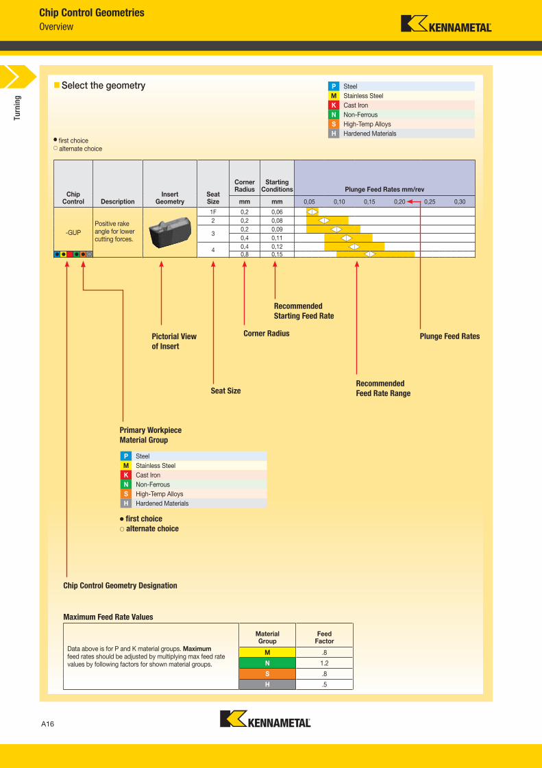
Chip Control Description
InsertGeometry
SeatSize
Corner Radius
Starting Conditions Plunge Feed Rates mm/rev
mm mm 0,05 0,10 0,15 0,20 0,25 0,30
-GUP
1F 0,2 0,06
2 0,2 0,08
30,2 0,09
0,4 0,11
40,4 0,12
0,8 0,15
Chip Control Geometries
Overview
� first choice� alternate choice
Plunge Feed Rates
Chip Control Geometry Designation
Primary Workpiece
Material Group
Pictorial View
of Insert
Seat Size
Corner Radius
Select the geometry P Steel
M Stainless Steel
K Cast Iron
N Non-Ferrous
S High-Temp Alloys
H Hardened Materials
P Steel
M Stainless Steel
K Cast Iron
N Non-Ferrous
S High-Temp Alloys
H Hardened Materials
� first choice� alternate choice
� � � � �
Recommended
Starting Feed Rate
Recommended
Feed Rate Range
Maximum Feed Rate Values
Positive rake angle for lower cutting forces.
Turn
ing
Data above is for P and K material groups. Maximum feed rates should be adjusted by multiplying max feed rate values by following factors for shown material groups.
Material Group
Feed Factor
M .8
N 1.2
S .8
H .5
A016_A017_KMT_Innovations_2016_Beyond_Evolution_Product_Brochure_016_017_EN_me.indd 16 7/28/15 1:16 PM
A17
L V i A016 A017 KMT I i 2016 B d E l i P d B h 016 017 EN J l202015741AM
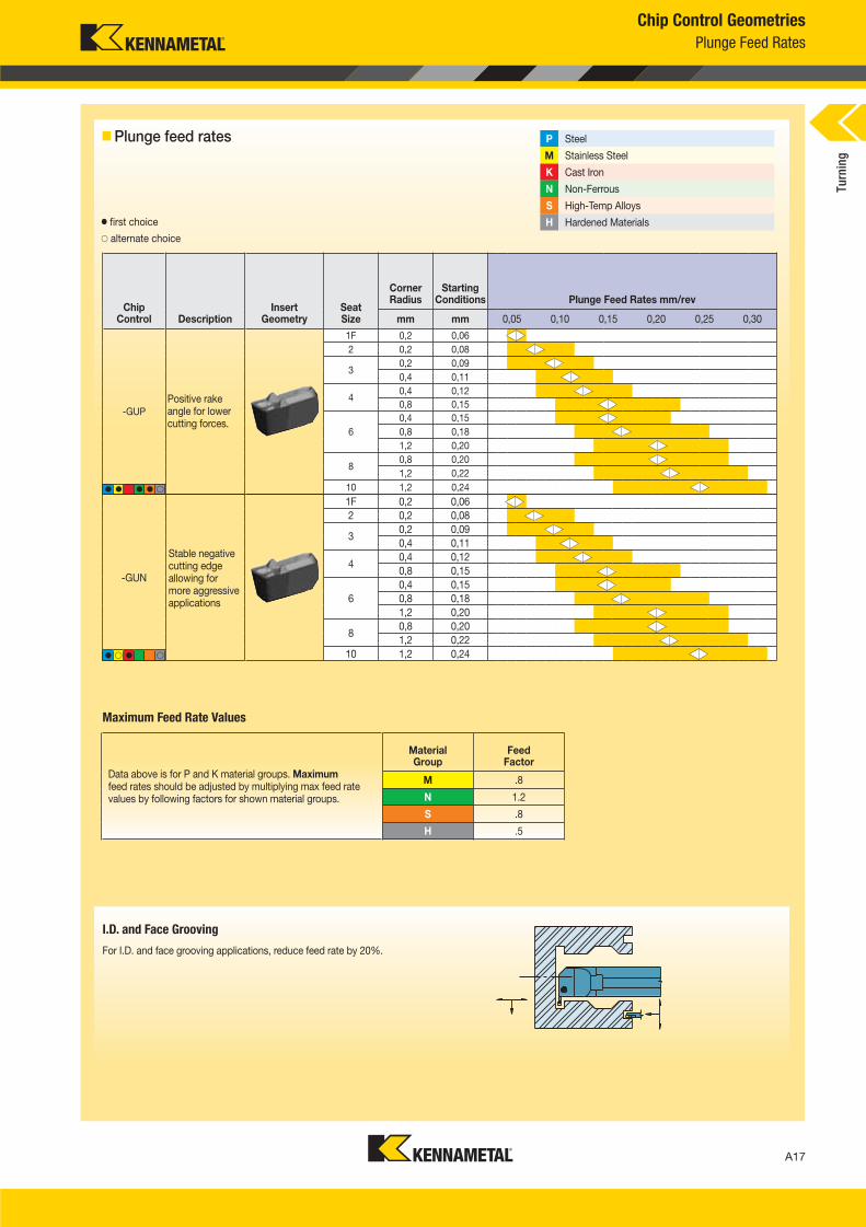
Chip Control Geometries
Plunge Feed Rates
Chip Control Description
InsertGeometry
SeatSize
Corner Radius
Starting Conditions Plunge Feed Rates mm/rev
mm mm 0,05 0,10 0,15 0,20 0,25 0,30
-GUP
1F 0,2 0,06
2 0,2 0,08
30,2 0,09
0,4 0,11
40,4 0,12
0,8 0,15
6
0,4 0,15
0,8 0,18
1,2 0,20
80,8 0,20
1,2 0,22
10 1,2 0,24
P Steel
M Stainless Steel
K Cast Iron
N Non-Ferrous
S High-Temp Alloys
H Hardened Materials
Plunge feed rates
� first choice
� alternate choice
Maximum Feed Rate Values
Data above is for P and K material groups. Maximum feed rates should be adjusted by multiplying max feed rate values by following factors for shown material groups.
Material Group
Feed Factor
M .8
N 1.2
S .8
H .5
Positive rake angle for lower cutting forces.
� � � � �
-GUN
1F 0,2 0,06
2 0,2 0,08
30,2 0,09
0,4 0,11
40,4 0,12
0,8 0,15
6
0,4 0,15
0,8 0,18
1,2 0,20
80,8 0,20
1,2 0,22
10 1,2 0,24� � � �
Stable negative cutting edge allowing for more aggressive applications
I.D. and Face Grooving
For I.D. and face grooving applications, reduce feed rate by 20%.
Turn
ing
A016_A017_KMT_Innovations_2016_Beyond_Evolution_Product_Brochure_016_017_EN_me.indd 17 7/28/15 1:16 PM
A18
L V i A018 A019 KMT I i 2016 B d E l i P d B h 018 019 EN J l 220158 32AM
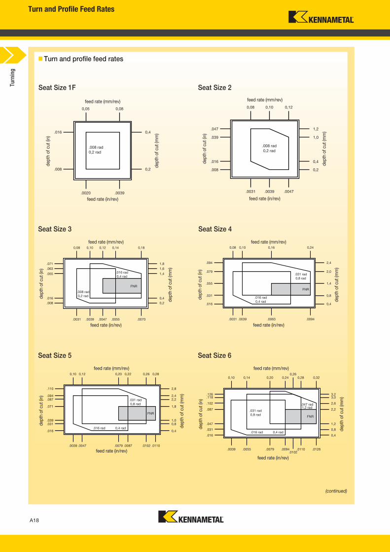
Turn and Profile Feed Rates
Turn and profile feed rates
feed rate (in/rev)
Seat Size 3
Seat Size 5
Seat Size 4
Seat Size 6
feed rate (mm/rev)
feed rate (in/rev)
dep
th o
f cu
t (in
)
dep
th o
f cu
t (m
m)
feed rate (mm/rev)
feed rate (in/rev)
dep
th o
f cu
t (in
)
dep
th o
f cu
t (m
m)
feed rate (mm/rev)
feed rate (in/rev)
dep
th o
f cu
t (in
)
dep
th o
f cu
t (m
m)
feed rate (mm/rev) feed rate (mm/rev)
feed rate (in/rev) feed rate (in/rev)
dep
th o
f cu
t (in
)
dep
th o
f cu
t (in
)
dep
th o
f cu
t (m
m)
dep
th o
f cu
t (m
m)
Seat Size 1F Seat Size 2
feed rate (mm/rev)
dep
th o
f cu
t (in
)
dep
th o
f cu
t (m
m)
0,10 0,14
.016 rad 0,4 rad
.047 rad1,2 rad
.031 rad0,8 rad FNR
0,28
.0039 .0055
0,20
.0079
0,24
.0094 .0110
0,32
.0126
0,26
.0102
.126
.102
.031
.016
3,2
2,6
.118 3,0
.087 2,2
0,8
.047 1,2
0,4
(continued)
Turn
ing
A018_A019_KMT_Innovations_2016_Beyond_Evolution_Product_Brochure_018_019_EN_me.indd 18 7/28/15 1:16 PM
A19
L V i A018 A019 KMT I i 2016 B d E l i P d B h 018 019 EN J l22015832AM
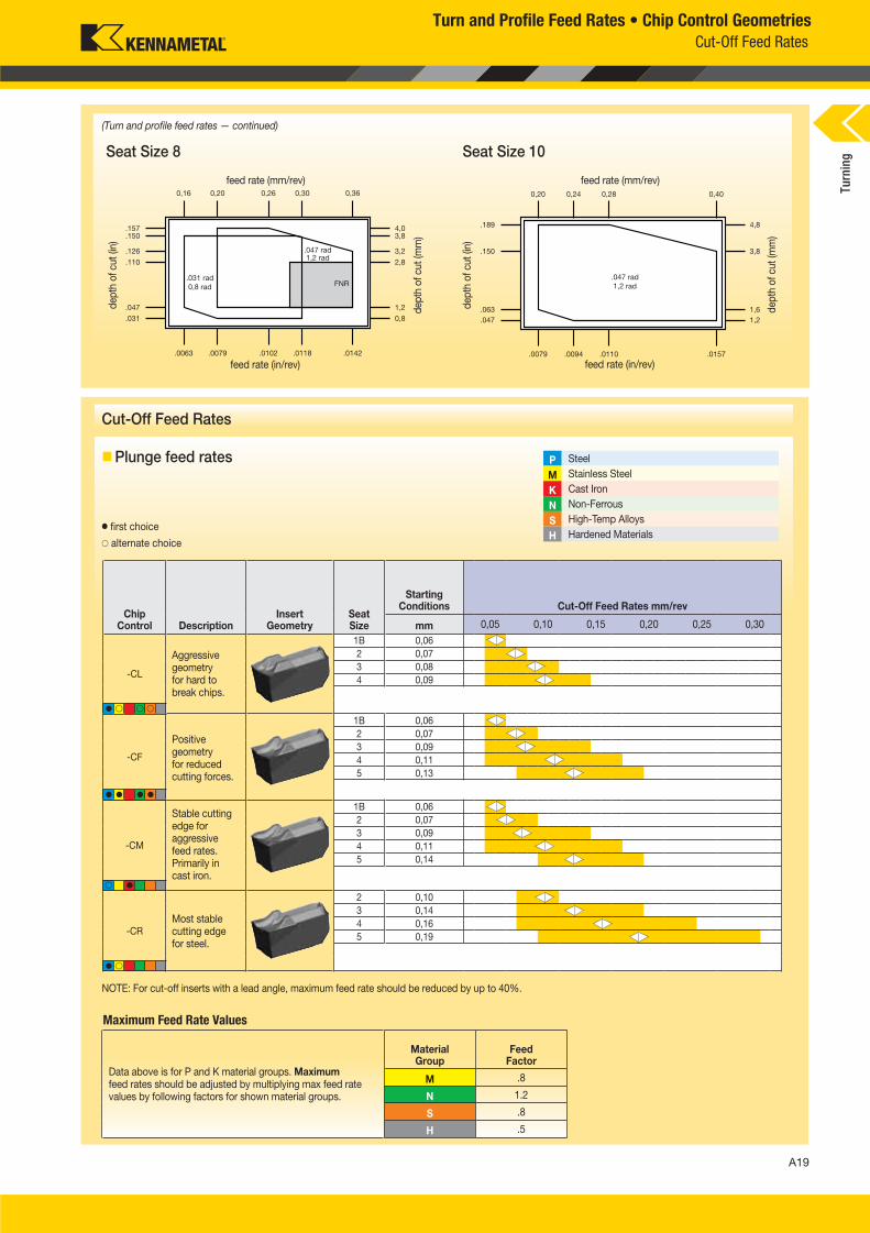
Plunge feed rates
� first choice
� alternate choice
P Steel
M Stainless Steel
K Cast Iron
N Non-Ferrous
S High-Temp Alloys
H Hardened Materials
Chip Control Description
InsertGeometry
SeatSize
Starting Conditions Cut-Off Feed Rates mm/rev
mm 0,05 0,10 0,15 0,20 0,25 0,30
-CL
1B 0,06
2 0,07
3 0,08
4 0,09
-CF
1B 0,06
2 0,07
3 0,09
4 0,11
5 0,13
-CM
1B 0,06
2 0,07
3 0,09
4 0,11
5 0,14
-CR
2 0,10
3 0,14
4 0,16
5 0,19
Seat Size 8 Seat Size 10
feed rate (mm/rev)
feed rate (in/rev)
dep
th o
f cu
t (in
)
dep
th o
f cu
t (m
m)
feed rate (mm/rev)
feed rate (in/rev)
dep
th o
f cu
t (in
)
dep
th o
f cu
t (m
m)
(Turn and profile feed rates — continued)
Cut-Off Feed Rates
Aggressive geometry for hard to break chips.
Positive geometry for reduced cutting forces.
Stable cutting edge for aggressive feed rates. Primarily in cast iron.
Most stable cutting edge for steel.
Turn and Profile Feed Rates • Chip Control Geometries
� �
� �
� � � �
� � � �
Cut-Off Feed Rates
NOTE: For cut-off inserts with a lead angle, maximum feed rate should be reduced by up to 40%.
Turn
ing
Maximum Feed Rate Values
Data above is for P and K material groups. Maximum feed rates should be adjusted by multiplying max feed rate values by following factors for shown material groups.
Material Group
Feed Factor
M .8
N 1.2
S .8
H .5
A018_A019_KMT_Innovations_2016_Beyond_Evolution_Product_Brochure_018_019_EN_me.indd 19 7/28/15 1:16 PM
A20
L V i A020 A021 KMT I i 2016 B d E l i P d B h 020 021 EN A 720151238PM
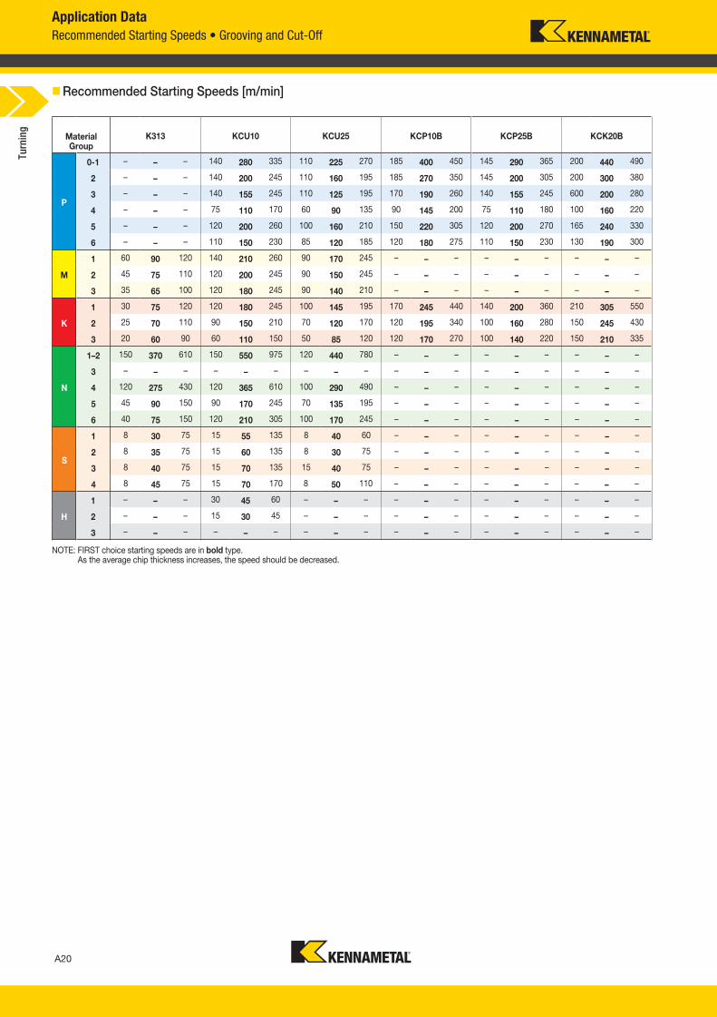
Application Data
Recommended Starting Speeds • Grooving and Cut-Off
NOTE: FIRST choice starting speeds are in bold type. As the average chip thickness increases, the speed should be decreased.
Recommended Starting Speeds [m/min]
MaterialGroup
K313 KCU10 KCU25 KCP10B KCP25B KCK20B
P
0-1 – – – 140 280 335 110 225 270 185 400 450 145 290 365 200 440 490
2 – – – 140 200 245 110 160 195 185 270 350 145 200 305 200 300 380
3 – – – 140 155 245 110 125 195 170 190 260 140 155 245 600 200 280
4 – – – 75 110 170 60 90 135 90 145 200 75 110 180 100 160 220
5 – – – 120 200 260 100 160 210 150 220 305 120 200 270 165 240 330
6 – – – 110 150 230 85 120 185 120 180 275 110 150 230 130 190 300
M
1 60 90 120 140 210 260 90 170 245 – – – – – – – – –
2 45 75 110 120 200 245 90 150 245 – – – – – – – – –
3 35 65 100 120 180 245 90 140 210 – – – – – – – – –
K
1 30 75 120 120 180 245 100 145 195 170 245 440 140 200 360 210 305 550
2 25 70 110 90 150 210 70 120 170 120 195 340 100 160 280 150 245 430
3 20 60 90 60 110 150 50 85 120 120 170 270 100 140 220 150 210 335
N
1–2 150 370 610 150 550 975 120 440 780 – – – – – – – – –
3 – – – – – – – – – – – – – – – – – –
4 120 275 430 120 365 610 100 290 490 – – – – – – – – –
5 45 90 150 90 170 245 70 135 195 – – – – – – – – –
6 40 75 150 120 210 305 100 170 245 – – – – – – – – –
S
1 8 30 75 15 55 135 8 40 60 – – – – – – – – –
2 8 35 75 15 60 135 8 30 75 – – – – – – – – –
3 8 40 75 15 70 135 15 40 75 – – – – – – – – –
4 8 45 75 15 70 170 8 50 110 – – – – – – – – –
H
1 – – – 30 45 60 – – – – – – – – – – – –
2 – – – 15 30 45 – – – – – – – – – – – –
3 – – – – – – – – – – – – – – – – – –
Turn
ing
A020_A021_KMT_Innovations_2016_Beyond_Evolution_Product_Brochure_020_021_EN_me.indd 20 8/7/15 12:41 PM
A21
L V i A020 A021 KMT I i 2016 B d E l i P d B h 020 021 EN A 720151238PM
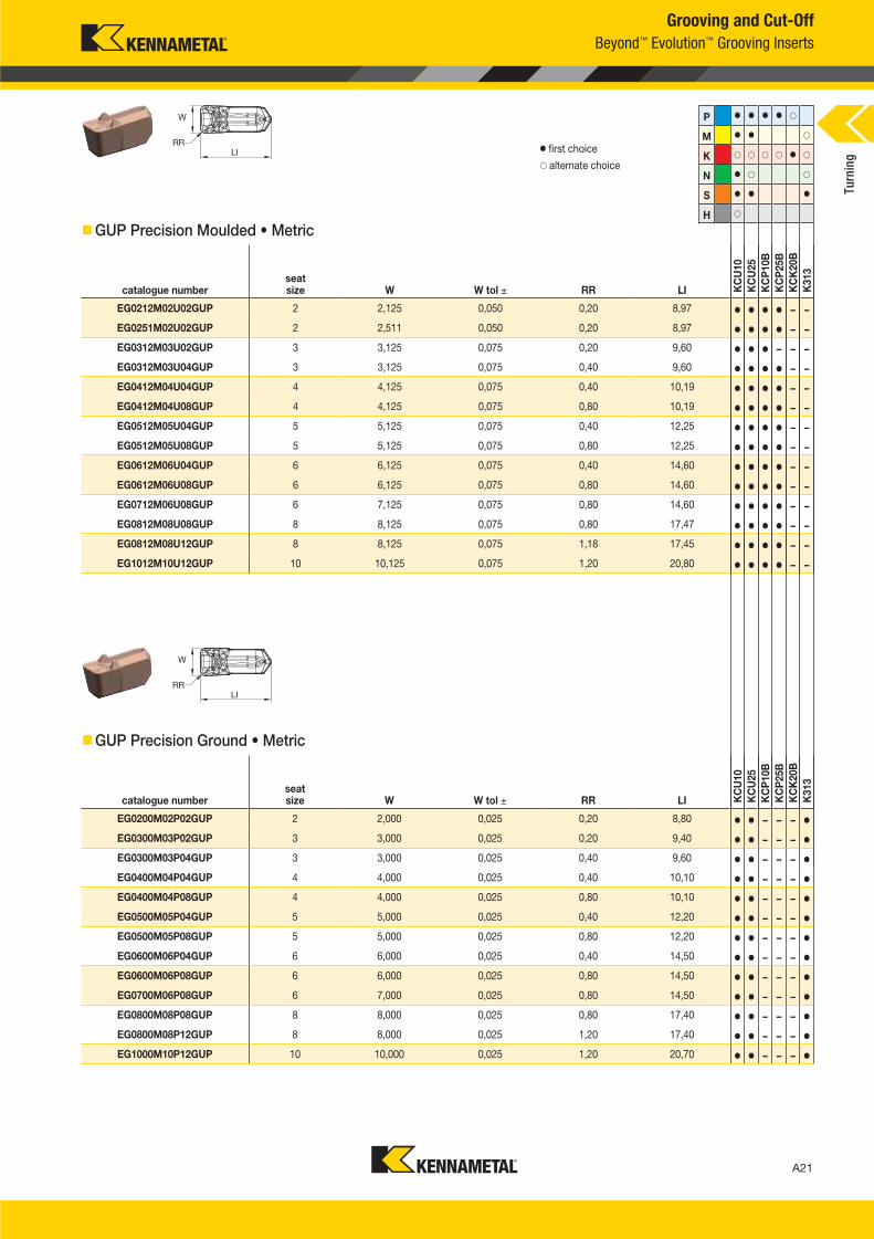
Grooving and Cut-Off
Beyond™ Evolution™ Grooving Inserts
GUP Precision Moulded • Metric
catalogue numberseat size W W tol ± RR LI K
CU
10
KC
U25
KC
P10B
KC
P25B
KC
K20B
K313
EG0212M02U02GUP 2 2,125 0,050 0,20 8,97 � � � � – –
EG0251M02U02GUP 2 2,511 0,050 0,20 8,97 � � � � – –
EG0312M03U02GUP 3 3,125 0,075 0,20 9,60 � � � – – –
EG0312M03U04GUP 3 3,125 0,075 0,40 9,60 � � � � – –
EG0412M04U04GUP 4 4,125 0,075 0,40 10,19 � � � � – –
EG0412M04U08GUP 4 4,125 0,075 0,80 10,19 � � � � – –
EG0512M05U04GUP 5 5,125 0,075 0,40 12,25 � � � � – –
EG0512M05U08GUP 5 5,125 0,075 0,80 12,25 � � � � – –
EG0612M06U04GUP 6 6,125 0,075 0,40 14,60 � � � � – –
EG0612M06U08GUP 6 6,125 0,075 0,80 14,60 � � � � – –
EG0712M06U08GUP 6 7,125 0,075 0,80 14,60 � � � � – –
EG0812M08U08GUP 8 8,125 0,075 0,80 17,47 � � � � – –
EG0812M08U12GUP 8 8,125 0,075 1,18 17,45 � � � � – –
EG1012M10U12GUP 10 10,125 0,075 1,20 20,80 � � � � – –
P � � � � �
M � � �
K � � � � � �
N � � �
S � � �
H �
GUP Precision Ground • Metric
catalogue numberseat size W W tol ± RR LI K
CU
10
KC
U25
KC
P10B
KC
P25B
KC
K20B
K313
EG0200M02P02GUP 2 2,000 0,025 0,20 8,80 � � – – – �
EG0300M03P02GUP 3 3,000 0,025 0,20 9,40 � � – – – �
EG0300M03P04GUP 3 3,000 0,025 0,40 9,60 � � – – – �
EG0400M04P04GUP 4 4,000 0,025 0,40 10,10 � � – – – �
EG0400M04P08GUP 4 4,000 0,025 0,80 10,10 � � – – – �
EG0500M05P04GUP 5 5,000 0,025 0,40 12,20 � � – – – �
EG0500M05P08GUP 5 5,000 0,025 0,80 12,20 � � – – – �
EG0600M06P04GUP 6 6,000 0,025 0,40 14,50 � � – – – �
EG0600M06P08GUP 6 6,000 0,025 0,80 14,50 � � – – – �
EG0700M06P08GUP 6 7,000 0,025 0,80 14,50 � � – – – �
EG0800M08P08GUP 8 8,000 0,025 0,80 17,40 � � – – – �
EG0800M08P12GUP 8 8,000 0,025 1,20 17,40 � � – – – �
EG1000M10P12GUP 10 10,000 0,025 1,20 20,70 � � – – – �
� first choice
� alternate choice
Turn
ing
A020_A021_KMT_Innovations_2016_Beyond_Evolution_Product_Brochure_020_021_EN_me.indd 21 8/7/15 12:41 PM
A22
L V i A022 A023 KMT I i 2016 B d E l i P d B h 022 023 EN J l 220157 53AM
Grooving and Cut-Off
Beyond™ Evolution™ Grooving Inserts
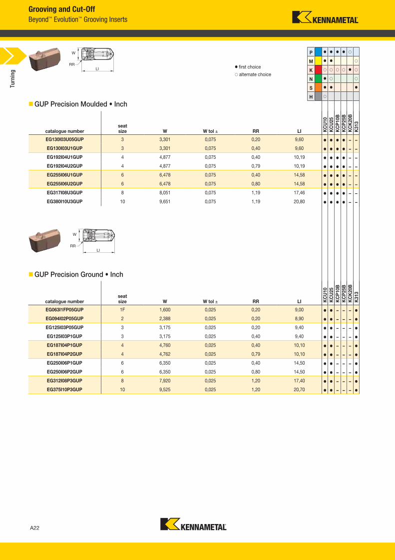
GUP Precision Moulded • Inch
� first choice
� alternate choice
P � � � � �
M � � �
K � � � � � �
N � � �
S � � �
H �
GUP Precision Ground • Inch
catalogue numberseat size W W tol ± RR LI K
CU
10
KC
U25
KC
P10B
KC
P25B
KC
K20B
K313
EG063I1FP05GUP 1F 1,600 0,025 0,20 9,00 � � – – – �
EG094I02P05GUP 2 2,388 0,025 0,20 8,90 � � – – – �
EG125I03P05GUP 3 3,175 0,025 0,20 9,40 � � – – – �
EG125I03P1GUP 3 3,175 0,025 0,40 9,40 � � – – – �
EG187I04P1GUP 4 4,760 0,025 0,40 10,10 � � – – – �
EG187I04P2GUP 4 4,762 0,025 0,79 10,10 � � – – – �
EG250I06P1GUP 6 6,350 0,025 0,40 14,50 � � – – – �
EG250I06P2GUP 6 6,350 0,025 0,80 14,50 � � – – – �
EG312I08P3GUP 8 7,920 0,025 1,20 17,40 � � – – – �
EG375I10P3GUP 10 9,525 0,025 1,20 20,70 � � – – – �
catalogue numberseat size W W tol ± RR LI K
CU
10
KC
U25
KC
P10B
KC
P25B
KC
K20B
K313
EG130I03U05GUP 3 3,301 0,075 0,20 9,60 � � � � – –
EG130I03U1GUP 3 3,301 0,075 0,40 9,60 � � � � – –
EG192I04U1GUP 4 4,877 0,075 0,40 10,19 � � � � – –
EG192I04U2GUP 4 4,877 0,075 0,79 10,19 � � � � – –
EG255I06U1GUP 6 6,478 0,075 0,40 14,58 � � � � – –
EG255I06U2GUP 6 6,478 0,075 0,80 14,58 � � � � – –
EG317I08U3GUP 8 8,051 0,075 1,19 17,46 � � � � – –
EG380I10U3GUP 10 9,651 0,075 1,19 20,80 � � � � – –
Turn
ing
A022_A023_KMT_Innovations_2016_Beyond_Evolution_Product_Brochure_022_023_EN_me.indd 22 7/28/15 1:16 PM
A23
L V i A022 A023 KMT I i 2016 B d E l i P d B h 022 023 EN J l22015753AM
Grooving and Cut-Off
Beyond™ Evolution™ Grooving Inserts
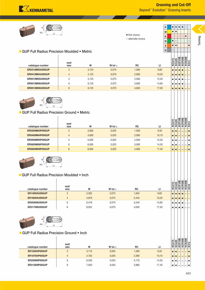
GUP Full Radius Precision Moulded • Metric
catalogue numberseat size W W tol ± RC LI K
CU
10
KC
U25
KC
P10B
KC
P25B
KC
K20B
K313
ER0312M03U00GUP 3 3,125 0,075 1,560 9,60 � � � � – –
ER0412M04U00GUP 4 4,125 0,075 2,060 10,20 � � � � – –
ER0512M05U00GUP 5 5,125 0,075 2,560 12,20 � � � � – –
ER0612M06U00GUP 6 6,125 0,075 3,060 14,60 � � � � – –
ER0812M08U00GUP 8 8,125 0,075 4,060 17,50 � � � � – –
� first choice
� alternate choice
GUP Full Radius Precision Ground • Metric
catalogue numberseat size W W tol ± RC LI K
CU
10
KC
U2
5
KC
P10B
KC
P25B
KC
K2
0B
K313
ER0300M03P00GUP 3 3,000 0,025 1,500 9,50 � � – – – �
ER0400M04P00GUP 4 4,000 0,025 2,000 10,10 � � – – – �
ER0500M05P00GUP 5 5,000 0,025 2,500 12,20 � � – – – �
ER0600M06P00GUP 6 6,000 0,025 3,000 14,50 � � – – – �
ER0800M08P00GUP 8 8,000 0,025 4,000 17,40 � � – – – �
GUP Full Radius Precision Moulded • Inch
catalogue numberseat size W W tol ± RC LI K
CU
10
KC
U25
KC
P10B
KC
P25B
KC
K20B
K313
ER130I03U00GUP 3 3,302 0,075 1,650 9,60 � � � � – –
ER192I04U00GUP 4 4,878 0,075 2,440 10,20 � � � � – –
ER255I06U00GUP 6 6,478 0,075 3,240 14,60 � � � � – –
ER317I08U00GUP 8 8,052 0,075 4,030 17,50 � � � � – –
GUP Full Radius Precision Ground • Inch
P � � � � �
M � � �
K � � � � � �
N � � �
S � � �
H �
catalogue numberseat size W W tol ± RC LI K
CU
10
KC
U2
5
KC
P1
0B
KC
P2
5B
KC
K20
B
K3
13
ER125I03P00GUP 3 3,175 0,025 1,590 9,50 � � – – – �
ER187I04P00GUP 4 4,762 0,025 2,380 10,10 � � – – – �
ER250I06P00GUP 6 6,350 0,025 3,170 14,50 � � – – – �
ER312I08P00GUP 8 7,920 0,025 3,960 17,40 � � – – – �
Turn
ing
A022_A023_KMT_Innovations_2016_Beyond_Evolution_Product_Brochure_022_023_EN_me.indd 23 7/28/15 1:16 PM
A24
L V i A024 A025 KMT I i 2016 B d E l i P d B h 024 025 EN J l 220157 53AM
Grooving and Cut-Off
Beyond™ Evolution™ Grooving Inserts
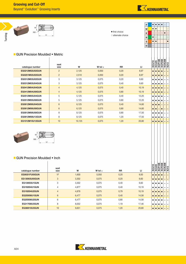
GUN Precision Moulded • Inch
catalogue numberseat size W W tol ± RR LI K
CU
10
KC
U25
KC
P10B
KC
P25B
KC
K20B
K313
EG063I1FU05GUN 1F 1,600 0,050 0,20 9,00 � � � � – –
EG130I03U05GUN 3 3,302 0,075 0,20 9,60 � � � � – –
EG130I03U1GUN 3 3,302 0,075 0,40 9,60 � � � � – –
EG192I04U1GUN 4 4,877 0,075 0,40 10,19 � � � � – –
EG192I04U2GUN 4 4,878 0,075 0,79 10,19 � � � � – –
EG255I06U1GUN 6 6,477 0,075 0,40 14,58 � � � � – –
EG255I06U2GUN 6 6,477 0,075 0,80 14,58 � � � � – –
EG317I08U3GUN 8 8,052 0,075 1,19 17,46 � � � � – –
EG380I10U3GUN 10 9,651 0,075 1,20 20,80 � � � � – –
� first choice
� alternate choice
GUN Precision Moulded • Metric
catalogue numberseat size W W tol ± RR LI K
CU
10
KC
U25
KC
P10B
KC
P25B
KC
K20B
K313
EG0212M02U02GUN 2 2,125 0,050 0,20 8,97 � � � � – –
EG0251M02U02GUN 2 2,510 0,050 0,20 8,97 � � � � – –
EG0312M03U02GUN 3 3,125 0,075 0,20 9,60 � � � � – –
EG0312M03U04GUN 3 3,125 0,075 0,40 9,60 � � � � – –
EG0412M04U04GUN 4 4,125 0,075 0,40 10,19 � � � � – –
EG0412M04U08GUN 4 4,125 0,075 0,80 10,19 � � � � – –
EG0512M05U04GUN 5 5,125 0,075 0,40 12,20 � � � � – –
EG0512M05U08GUN 5 5,125 0,075 0,80 12,20 � � � � – –
EG0612M06U04GUN 6 6,125 0,075 0,40 14,60 � � � – – –
EG0612M06U08GUN 6 6,125 0,075 0,80 14,60 � � – � – –
EG0812M08U08GUN 8 8,125 0,075 0,80 17,50 � � � � – –
EG0812M08U12GUN 8 8,125 0,075 1,20 17,50 � � � � – –
EG1012M10U12GUN 10 10,125 0,075 1,20 20,80 � � � � – –
P � � � � �
M � � �
K � � � � � �
N � � �
S � � �
H �
Turn
ing
A024_A025_KMT_Innovations_2016_Beyond_Evolution_Product_Brochure_024_025_EN_me.indd 24 7/28/15 1:16 PM
A25
L V i A024 A025 KMT I i 2016 B d E l i P d B h 024 025 EN J l22015753AM
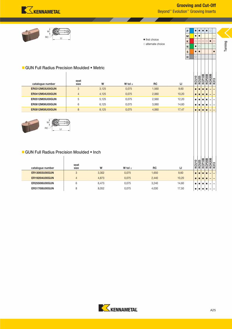
GUN Full Radius Precision Moulded • Metric
catalogue numberseat size W W tol ± RC LI K
CU
10
KC
U25
KC
P10B
KC
P25B
KC
K20B
K313
ER0312M03U00GUN 3 3,125 0,075 1,560 9,60 � � � � – –
ER0412M04U00GUN 4 4,125 0,075 2,060 10,20 � � � � – –
ER0512M05U00GUN 5 5,125 0,075 2,560 12,20 � � � � – –
ER0612M06U00GUN 6 6,125 0,075 3,060 14,60 � � � � – –
ER0812M08U00GUN 8 8,125 0,075 4,060 17,47 � � � � – –
Grooving and Cut-Off
Beyond™ Evolution™ Grooving Inserts
GUN Full Radius Precision Moulded • Inch
� first choice
� alternate choice
catalogue numberseat size W W tol ± RC LI K
CU
10
KC
U25
KC
P10B
KC
P25B
KC
K20B
K313
ER130I03U00GUN 3 3,302 0,075 1,650 9,60 � � � � – –
ER192I04U00GUN 4 4,873 0,075 2,440 10,20 � � � � – –
ER255I06U00GUN 6 6,473 0,075 3,240 14,60 � � � � – –
ER317I08U00GUN 8 8,052 0,075 4,030 17,50 � � � � – –
P � � � � �
M � � �
K � � � � � �
N � � �
S � � �
H �
Turn
ing
A024_A025_KMT_Innovations_2016_Beyond_Evolution_Product_Brochure_024_025_EN_me.indd 25 7/28/15 1:16 PM
A26
L V i A026 A027 KMT I i 2016 B d E l i P d B h 026 027 EN J l 220157 53AM
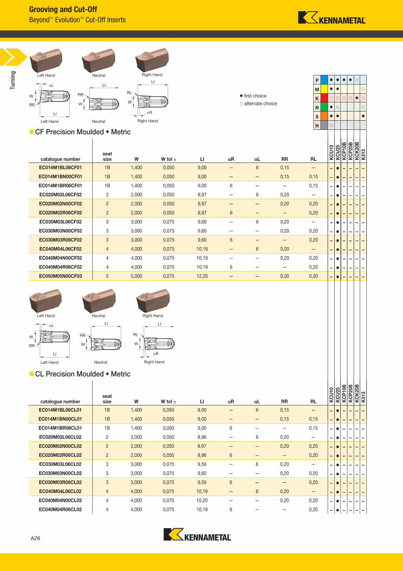
Grooving and Cut-Off
Beyond™ Evolution™ Cut-Off Inserts
� first choice
� alternate choice
Right HandNeutralLeft Hand
Right HandNeutralLeft Hand
CF Precision Moulded • Metric
catalogue numberseat size W W tol ± LI R L RR RL K
CU
10
KC
U25
KC
P10B
KC
P25B
KC
K20B
K313
EC014M1BL06CF01 1B 1,400 0,050 9,00 — 6 0,15 — – � – – – –
EC014M1BN00CF01 1B 1,400 0,050 9,00 — — 0,15 0,15 – � – – – –
EC014M1BR06CF01 1B 1,400 0,050 9,00 6 — — 0,15 – � – – – –
EC020M02L06CF02 2 2,000 0,050 8,97 — 6 0,20 — – � – – – –
EC020M02N00CF02 2 2,000 0,050 8,97 — — 0,20 0,20 – � – – – –
EC020M02R06CF02 2 2,000 0,050 8,97 6 — — 0,20 – � – – – –
EC030M03L06CF02 3 3,000 0,075 9,60 — 6 0,20 — – � – – – –
EC030M03N00CF02 3 3,000 0,075 9,60 — — 0,20 0,20 – � – – – –
EC030M03R06CF02 3 3,000 0,075 9,60 6 — — 0,20 – � – – – –
EC040M04L06CF02 4 4,000 0,075 10,19 — 6 0,20 — – � – – – –
EC040M04N00CF02 4 4,000 0,075 10,19 — — 0,20 0,20 – � – – – –
EC040M04R06CF02 4 4,000 0,075 10,19 6 — — 0,20 – � – – – –
EC050M05N00CF03 5 5,000 0,075 12,20 — — 0,30 0,30 – � – – – –
CL Precision Moulded • Metric
catalogue numberseat size W W tol ± LI R L RR RL K
CU
10
KC
U25
KC
P10B
KC
P25B
KC
K20B
K313
EC014M1BL06CL01 1B 1,400 0,050 9,00 — 6 0,15 — – � – – – –
EC014M1BN00CL01 1B 1,400 0,050 9,00 — — 0,15 0,15 – � – – – –
EC014M1BR06CL01 1B 1,400 0,050 9,00 6 — — 0,15 – � – – – –
EC020M02L06CL02 2 2,000 0,050 8,96 — 6 0,20 — – � – – – –
EC020M02N00CL02 2 2,000 0,050 8,97 — — 0,20 0,20 – � – – – –
EC020M02R06CL02 2 2,000 0,050 8,96 6 — — 0,20 – � – – – –
EC030M03L06CL02 3 3,000 0,075 9,59 — 6 0,20 — – � – – – –
EC030M03N00CL02 3 3,000 0,075 9,60 — — 0,20 0,20 – � – – – –
EC030M03R06CL02 3 3,000 0,075 9,59 6 — — 0,20 – � – – – –
EC040M04L06CL02 4 4,000 0,075 10,19 — 6 0,20 — – � – – – –
EC040M04N00CL02 4 4,000 0,075 10,20 — — 0,20 0,20 – � – – – –
EC040M04R06CL02 4 4,000 0,075 10,19 6 — — 0,20 – � – – – –
Right HandNeutralLeft Hand
Right HandNeutralLeft Hand
P � � � � �
M � � �
K � � � � � �
N � � �
S � � �
H �
Turn
ing
A026_A027_KMT_Innovations_2016_Beyond_Evolution_Product_Brochure_026_027_EN_me.indd 26 7/28/15 1:16 PM
A27
L V i A026 A027 KMT I i 2016 B d E l i P d B h 026 027 EN J l22015753AM
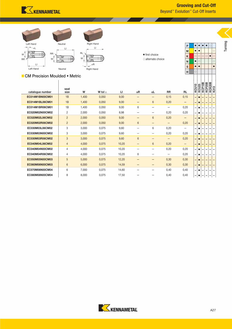
Grooving and Cut-Off
Beyond™ Evolution™ Cut-Off Inserts
� first choice
� alternate choice
Right HandNeutralLeft Hand
Right HandNeutralLeft HandP � � � � �
M � � �
K � � � � � �
N � � �
S � � �
H �
CM Precision Moulded • Metric
catalogue numberseat size W W tol ± LI R L RR RL K
CU
10
KC
U25
KC
P10B
KC
P25B
KC
K20B
K313
EC014M1BN00CM01 1B 1,400 0,050 9,00 — — 0,15 0,15 – � – – – –
EC014M1BL06CM01 1B 1,400 0,050 9,00 — 6 0,20 — – � – – – –
EC014M1BR06CM01 1B 1,400 0,050 9,00 6 — — 0,20 – � – – – –
EC020M02N00CM02 2 2,000 0,050 8,98 — — 0,20 0,20 – � – – – –
EC020M02L06CM02 2 2,000 0,050 9,00 — 6 0,20 — – � – – – –
EC020M02R06CM02 2 2,000 0,050 9,00 6 — — 0,20 – � – – – –
EC030M03L06CM02 3 3,000 0,075 9,60 — 6 0,20 — – � – – – –
EC030M03N00CM02 3 3,000 0,075 9,60 — — 0,20 0,20 – � – – – –
EC030M03R06CM02 3 3,000 0,075 9,60 6 — — 0,20 – � – – – –
EC040M04L06CM02 4 4,000 0,075 10,20 — 6 0,20 — – � – – – –
EC040M04N00CM02 4 4,000 0,075 10,20 — — 0,20 0,20 – � – – – –
EC040M04R06CM02 4 4,000 0,075 10,20 6 — — 0,20 – � – – – –
EC050M05N00CM03 5 5,000 0,075 12,20 — — 0,30 0,30 – � – – – –
EC060M06N00CM03 6 6,000 0,075 14,59 — — 0,30 0,30 – � – – – –
EC070M06N00CM04 6 7,000 0,075 14,60 — — 0,40 0,40 – � – – – –
EC080M08N00CM04 8 8,000 0,075 17,50 — — 0,40 0,40 – � – – – –
Turn
ing
A026_A027_KMT_Innovations_2016_Beyond_Evolution_Product_Brochure_026_027_EN_me.indd 27 7/28/15 1:16 PM
A28
L V i A028 A029 KMT I i 2016 B d E l i P d B h 028 029 EN J l 242015241PM
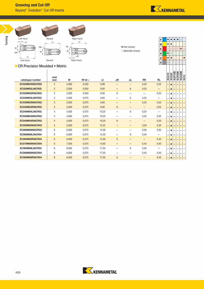
Grooving and Cut-Off
Beyond™ Evolution™ Cut-Off Inserts
CR Precision Moulded • Metric
catalogue numberseat size W W tol ± LI R L RR RL K
CU
10
KC
U25
KC
P10B
KC
P25B
KC
K20B
K313
EC020M02N00CR02 2 2,000 0,050 8,98 — — 0,20 0,20 – � – – – –
EC020M02L06CR02 2 2,000 0,050 9,00 — 6 0,20 — – � – – – –
EC020M02R06CR02 2 2,000 0,050 9,00 6 — — 0,20 – � – – – –
EC030M03L06CR02 3 3,000 0,075 9,60 — 6 0,20 — – � – – – –
EC030M03N00CR02 3 3,000 0,075 9,60 — — 0,20 0,20 – � – – – –
EC030M03R06CR02 3 3,000 0,075 9,60 6 — — 0,20 – � – – – –
EC040M04L06CR02 4 4,000 0,075 10,20 — 6 0,20 — – � – – – –
EC040M04N00CR02 4 4,000 0,075 10,20 — — 0,20 0,20 – � – – – –
EC040M04R06CR02 4 4,000 0,075 10,20 6 — — 0,20 – � – – – –
EC050M05N00CR03 5 5,000 0,075 12,25 — — 0,30 0,30 – � – – – –
EC060M06N00CR03 6 6,000 0,075 14,59 — — 0,30 0,30 – � – – – –
EC060M06L06CR04 6 6,000 0,075 14,59 — 6 0,40 — – � – – – –
EC060M06R06CR04 6 6,000 0,075 14,59 6 — — 0,40 – � – – – –
EC070M06N00CR04 6 7,000 0,075 14,60 — — 0,40 0,40 – � – – – –
EC080M08L06CR04 8 8,000 0,075 17,50 — 6 0,40 — – � – – – –
EC080M08N00CR04 8 8,000 0,075 17,50 — — 0,40 0,40 – � – – – –
EC080M08R06CR04 8 8,000 0,075 17,50 6 — — 0,40 – � – – – –
� first choice
� alternate choice
P � � � � �
M � � �
K � � � � � �
N � � �
S � � �
H �Right HandNeutralLeft Hand
Right HandNeutralLeft Hand
Turn
ing
A028_A029_KMT_Innovations_2016_Beyond_Evolution_Product_Brochure_028_029_EN_me.indd 28 8/7/15 12:49 PM

L V i A028 A029 KMT I i 2016 B d E l i P d B h 028 029 EN J l242015241PM
Any project, any challenge, optimised and refined using digital intelligence to
fundamentally transform your workflow into seamless, elegant, simple production.
From art to part — to profit.
With NOVO™ you can now have the right tools on your machines, in the right sequence.
This enterprise-wide solution ensures that you execute flawlessly to accelerate every job,
and maximise every shift.
Experience digital intelligence that will transform
your manufacturing process: www.kennametal.com/novo
Experience Powering Productivity™
A028_A029_KMT_Innovations_2016_Beyond_Evolution_Product_Brochure_028_029_EN_me.indd 29 8/7/15 12:49 PM
A30
L V i A030 A031 KMT I i 2016 B d E l i P d B h 030 031 EN J l 142015824AM
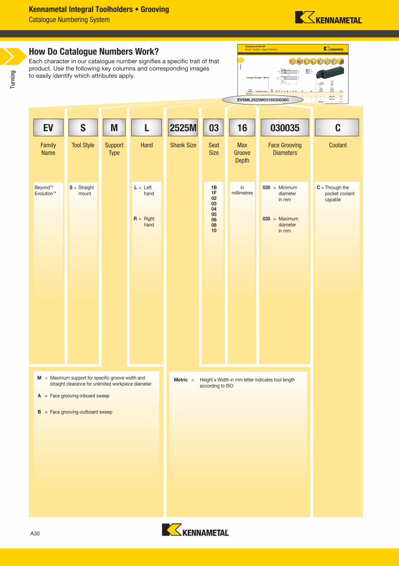
Kennametal Integral Toolholders • Grooving
Catalogue Numbering System
Each character in our catalogue number signifies a specific trait of that
product. Use the following key columns and corresponding images
to easily identify which attributes apply.
How Do Catalogue Numbers Work?Grooving and Cut-Off
Beyond™ Evolution™ Integral Toolholders
Integral Straight • Metric
order number catalogue number
seat size CD H1 H B H2 L1 FS LH CF CS
Torx clamp screw
Torx clamp screw Torx
left hand
5953956 EVSML2020K0216 2 16 20 20 20 27 125 19 31 — — — MS1160 T20
5953954 EVSML2525M0216 2 16 25 25 25 32 150 24 31 — — — MS1160 T20
5953955 EVSML2020K0222 2 22 20 20 20 29 125 19 38 — — MS2091 — 25 IP
EVSML2 2 M0226 2 26 2 2 2 34 1 0 24 42 2 IP
Turn
ing
M = Maximum support for specific groove width and
straight clearance for unlimited workpiece diameter
A = Face grooving-inboard sweep
B = Face grooving-outboard sweep
56 EVSML2020K0216 223955953595395953953955953
EVSVSMLEVSML2525M0316030035C
EV S M L 2525M 03 16 030035 C
Family
Name
Tool Style Support
Type
Hand Shank Size Seat
Size
Max
Groove
Depth
Face Grooving
Diameters
Coolant
Beyond™
Evolution™
S = Straight
mount
L = Left
hand
1B1F02030405060810
in millimetres
030 = Minimum
diameter
in mm
C = Through the
pocket coolant
capable
R = Right
hand
035 = Maximum
diameter
in mm
Metric = Height x Width in mm letter indicates tool length
according to ISO
Turn
ing
A030_A031_KMT_Innovations_2016_Beyond_Evolution_Product_Brochure_030_031_EN_me.indd 30 7/28/15 1:16 PM
A31
L V i A030 A031 KMT I i 2016 B d E l i P d B h 030 031 EN J l142015824AM
How Do Catalogue Numbers Work?Grooving and Cut-Off
Beyond™ Evolution™ Integral Toolholders
Integral Straight Top Clamp • Metric
order number catalogue number
seat size CD
D max H1 H B H2 H3 L1 FS LH CF CS
Torx clamp screw
Torx clamp screw Torx
right hand
5980139 EVSCTR1616K0216 2 16 42 16 16 16 23 — 125 15 31 — — — MS1160 T20
5980762 EVSCTR2020K0216 2 16 42 20 20 20 27 — 125 19 31 — — — MS1160 T20
5980767 EVSCTR2525M0216 2 16 42 25 25 25 32 — 150 24 31 — — — MS1160 T20
Turn
ing
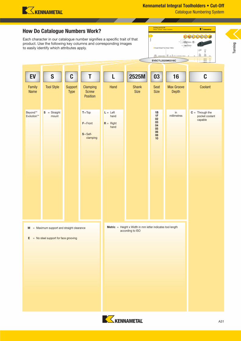
Kennametal Integral Toolholders • Cut-Off
Catalogue Numbering System
Each character in our catalogue number signifies a specific trait of that
product. Use the following key columns and corresponding images
to easily identify which attributes apply.
M = Maximum support and straight clearance
E = No steel support for face grooving
t hand
9859
393
EVV
CTT
CTCT
25252 6 4EVSCTL2525M0316C
Metric = Height x Width in mm letter indicates tool length
according to ISO
EV S C T L 2525M 03 16 C
Family
Name
Tool Style Support
Type
Clamping
Screw
Position
Hand Shank
Size
Seat
Size
Max Groove
Depth
Coolant
Beyond™
Evolution™
S = Straight
mount
T=Top L = Left
hand
1B1F02030405060810
in millimetres
C = Through the
pocket coolant
capableF=Front R = Right
hand
S=Self-
clamping
Turn
ing
A030_A031_KMT_Innovations_2016_Beyond_Evolution_Product_Brochure_030_031_EN_me.indd 31 7/28/15 1:16 PM
A32
L V i A032 A033 KMT I i 2016 B d E l i P d B h 032 033 EN J l 220157 17AM
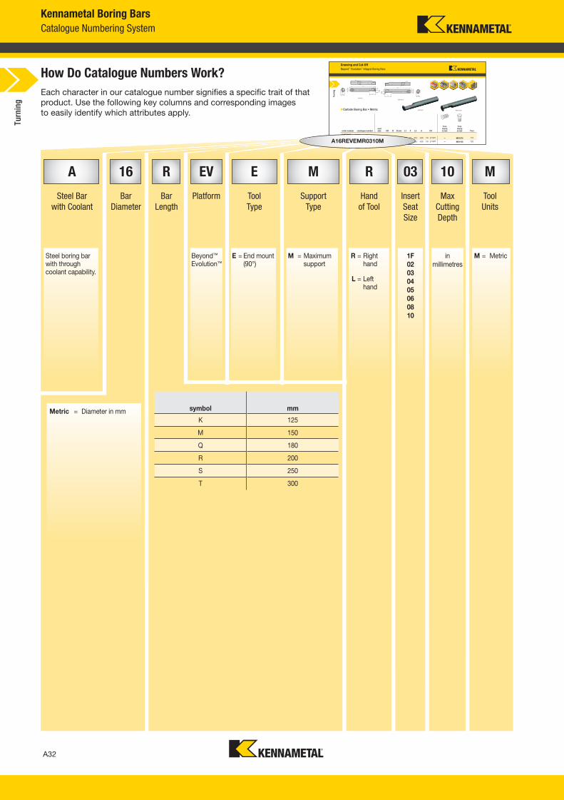
Kennametal Boring Bars
Catalogue Numbering System
symbol mm
K 125
M 150
Q 180
R 200
S 250
T 300
Each character in our catalogue number signifies a specific trait of that
product. Use the following key columns and corresponding images
to easily identify which attributes apply.
How Do Catalogue Numbers Work?Grooving and Cut-Off
Beyond™ Evolution™ Integral Boring Bars
Carbide Boring Bar • Metric
order number catalogue numberseat size CD D D min L1 F L4 A CS
Torx clamp screw
Torx clamp screw Torx
right hand
5954259 A16MEVEMR0307M 3 7,00 16 20 150 11 40,3 4,00 1/8 - 27 NPT — MS1273 T15
5954260 A20QEVEMR0307M 3 7,00 20 25 180 13 40,3 4,00 1/8 - 27 NPT — MS1160 T20
A25REVEMR0310M 3 10 00 25 32 200 17 50 3 6 40 1/4 18 NPT T25
Right Hand
Left Hand
Right HandLeft Hand
Turn
ing
7M
00
MEVA1A16M6ME5959 A MR03EVEMR 07MME
QEVA20Q
EE
A16REVEMR0310M
A 16 R EV E M R 03 10 M
Steel Bar
with Coolant
Bar
Diameter
Bar
Length
Platform Tool
Type
Support
Type
Hand
of Tool
Insert
Seat
Size
Max
Cutting
Depth
Tool
Units
Steel boring bar with through coolant capability.
Beyond™ Evolution™
E = End mount (90°)
M = Maximum support
R = Right hand
1F
02
03
04
05
06
08
10
in
millimetres
M = Metric
L = Left hand
Metric = Diameter in mm
Turn
ing
A032_A033_KMT_Innovations_2016_Beyond_Evolution_Product_Brochure_032_033_EN_me.indd 32 7/28/15 1:16 PM
A33
L V i A032 A033 KMT I i 2016 B d E l i P d B h 032 033 EN J l22015717AM
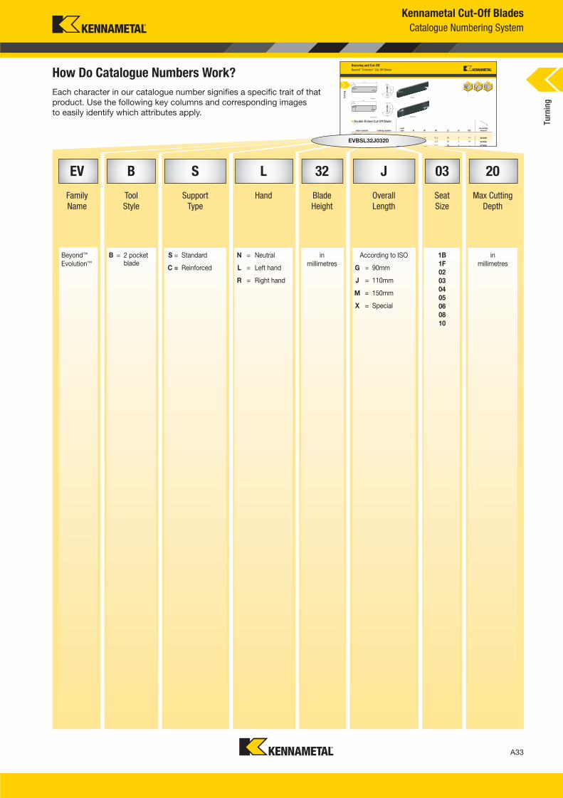
Kennametal Cut-Off Blades
Catalogue Numbering System
Each character in our catalogue number signifies a specific trait of that
product. Use the following key columns and corresponding images
to easily identify which attributes apply.
How Do Catalogue Numbers Work?Grooving and Cut-Off
Beyond™ Evolution™ Cut-Off Blades
Double-Ended Cut-Off Blade
order number catalog numberseat size H W H1 L1 B CD
assembly wrench
left hand
5941706 EVBSN19G1B14 1B 19 1,4 15,5 90 2 14 SCW5E
5955391 EVBSN19G1F16 1F 19 1,6 15,5 90 2 16 SCW5E
5941707 EVBSN19G0220 2 19 2,0 15,5 90 2 — SCW5E
Reinforced
Straight
Reinforced
StraightTurn
ing
E
6
2,,EVBSNSN19
706 EVBEV
EVBSL32J0320
EV B S L 32 J 03 20
Family
Name
Tool
Style
Support
Type
Hand Blade
Height
Overall
Length
Seat
Size
Max Cutting
Depth
Beyond™
Evolution™
B = 2 pocket blade
S = Standard N = Neutral in
millimetres
According to ISO 1B
1F
02
03
04
05
06
08
10
in
millimetresC = Reinforced L = Left hand G = 90mm
R = Right hand J = 110mm
M = 150mm
X = Special
Turn
ing
A032_A033_KMT_Innovations_2016_Beyond_Evolution_Product_Brochure_032_033_EN_me.indd 33 7/28/15 1:16 PM
A34
L V i A034 A035 KMT I i 2016 B d E l i P d B h 034 035 EN J l 620151258PM
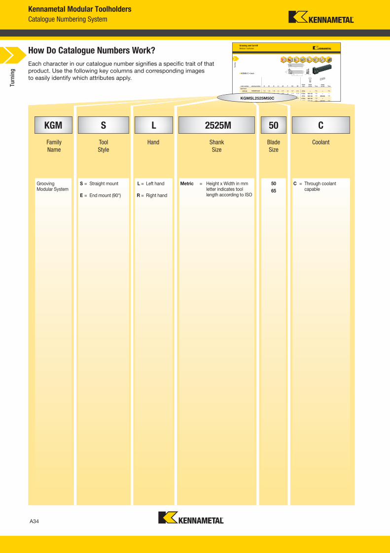
Kennametal Modular Toolholders
Catalogue Numbering System
Each character in our catalogue number signifies a specific trait of that
product. Use the following key columns and corresponding images
to easily identify which attributes apply.
How Do Catalogue Numbers Work?Grooving and Cut-Off
Modular Toolholder
KGMS-C • Inch
order number catalog number H H1 B L1 LS F H2 H3blade size
blade screw Torx
clampscrew Torx
right hand
5979194 KGMSR1650C 1.00 1.00 1.00 5.5 4.27 .56 1.67 6,35 KT25 — T25 — T25
5979801 KGMSR1665C 1.00 1.00 1.00 6.0 4.62 .53 2.10 12,70 KT30L MS1163 T30 — —
5979802 KGMSR2050C 1.25 1.25 1.25 5.5 4.72 .81 1.78 — KT25 MS1162 T25 MS2002 T25
5979803 KGMSR2065C 1.25 1.25 1.25 6.0 4.88 .78 2.09 6,35 KT30L MS1163 T30 — —
5979804 KGMSR2450C 1.50 1.50 1.50 5.5 4.72 1.06 2.03 — KT25 MS1162 T25 MS2002 T25
Turn
ing
07980
KGMSL2525M50C
KGM S L 2525M 50 C
Family
Name
Tool
Style
Hand Shank
Size
Blade
Size
Coolant
Grooving Modular System
S = Straight mount L = Left hand Metric = Height x Width in mm letter indicates tool length according to ISO
50
65
C = Through coolant capable
E = End mount (90°) R = Right hand
Turn
ing
A034_A035_KMT_Innovations_2016_Beyond_Evolution_Product_Brochure_034_035_EN_me.indd 34 7/28/15 1:16 PM
A35
L V i A034 A035 KMT I i 2016 B d E l i P d B h 034 035 EN J l620151258PM
Grooving and Cut-Off
Beyond™ Evolution™ Modular Blades
Modular Straight Blade with Coolant
order number catalog numberseat size CD FS
blade size
right hand
6031041 EVM50R1F12M 1F 12,0 11,00 50
6030969 EVM50R0212M 2 12,0 10,88 50
5955423 EVM50R0216MC 2 16,0 10,88 50
5979200 EVM50R0312MC 3 12,0 10,43 50
5979010 EVM50R0316MC 3 16,0 10,43 50
Right Hand
Left Hand
Right Hand
Left Hand
Right HandLeft Hand
Left Hand Right Hand
Turn
ing
EVM50L0314M30035C
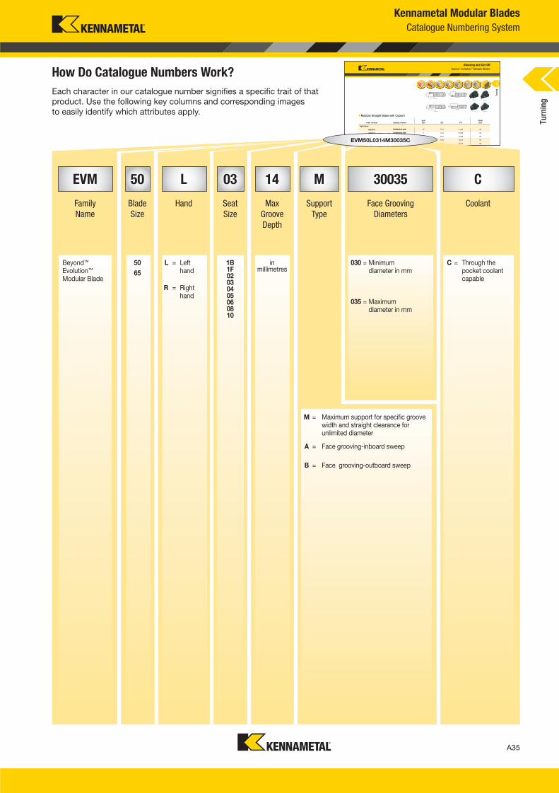
Kennametal Modular Blades
Catalogue Numbering System
EVM 50 L 03 14 M 30035 C
Family
Name
Blade
Size
Hand Seat
Size
Max
Groove
Depth
Support
Type
Face Grooving
Diameters
Coolant
Beyond™ Evolution™ Modular Blade
50
65
L = Left hand
1B1F02030405060810
in millimetres
030 = Minimum diameter in mm
C = Through the pocket coolant capable
R = Right hand
035 = Maximum diameter in mm
Each character in our catalogue number signifies a specific trait of that
product. Use the following key columns and corresponding images
to easily identify which attributes apply.
How Do Catalogue Numbers Work?
M = Maximum support for specific groove width and straight clearance for unlimited diameter
A = Face grooving-inboard sweep
B = Face grooving-outboard sweep
Turn
ing
A034_A035_KMT_Innovations_2016_Beyond_Evolution_Product_Brochure_034_035_EN_me.indd 35 7/28/15 1:16 PM
A36
L V i A036 A037 KMT I i 2016 B d E l i P d B h 036 037 EN J l 220154 40PM
Grooving and Cut-Off
Beyond™ Evolution™ Modular KM™ Units
Modular Straight KM System with Coolant
L1 F
order number catalog numberCSMS
system size mm in mm inblade screw Torx
clampscrew Torx
right hand
3950268 KM40TSKGMSR50 KM40TS 53,5 2.11 15,0 .59 MS1162 T25 MS2002 T25
5999790 KM40TSKGMSR50C KM40TS 53,5 2.11 15,0 .59 MS1162 T25 MS2002 T25
5999864 KM50TSKGMSR50C KM50TS 58,5 2.30 23,0 .91 MS1162 T25 MS2002 T25
3590203 KM63TSKGMSR65 KM63TS 58 5 2 30 30 0 1 18 MS1163 T30
L1 F
Turn
ing
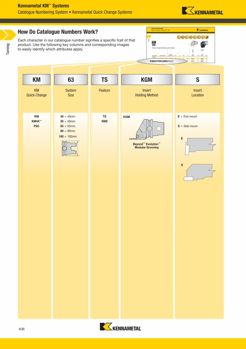
Kennametal KM™ Systems
Catalogue Numbering System • Kennametal Quick Change Systems
Each character in our catalogue number signifies a specific trait of that
product. Use the following key columns and corresponding images
to easily identify which attributes apply.
How Do Catalogue Numbers Work?
E
S
KM 63 TS KGM S
KM
Quick Change
System
Size
Feature Insert
Holding Method
Insert
Location
KM 40 = 40mm TS KGM E = End mount
KM4X™ 50 = 50mm XMZ
PSC 63 = 63mm S = Side mount
80 = 80mm
100 = 100mm
Beyond™ Evolution™ Modular Grooving
KM63TSKGMSR50C
Turn
ing
A036_A037_KMT_Innovations_2016_Beyond_Evolution_Product_Brochure_036_037_EN_me.indd 36 7/28/15 1:16 PM
A37
L V i A036 A037 KMT I i 2016 B d E l i P d B h 036 037 EN J l22015440PM
Grooving and Cut-Off
Beyond™ Evolution™ Modular KM™ Units
Modular Straight KM System with Coolant
L1 F
order number catalog numberCSMS
system size mm in mm inblade screw Torx
clampscrew Torx
right hand
3950268 KM40TSKGMSR50 KM40TS 53,5 2.11 15,0 .59 MS1162 T25 MS2002 T25
5999790 KM40TSKGMSR50C KM40TS 53,5 2.11 15,0 .59 MS1162 T25 MS2002 T25
5999864 KM50TSKGMSR50C KM50TS 58,5 2.30 23,0 .91 MS1162 T25 MS2002 T25
3590203 KM63TSKGMSR65 KM63TS 58 5 2 30 30 0 1 18 MS1163 T30
L1 F
Turn
ing
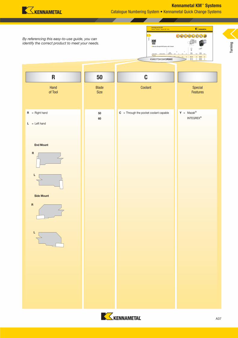
Kennametal KM™ Systems
Catalogue Numbering System • Kennametal Quick Change Systems
R
KM63TSKGMSR50C
By referencing this easy-to-use guide, you can
identify the correct product to meet your needs.
R 50 C
Hand
of Tool
Blade
Size
Coolant Special
Features
R = Right hand 50 C = Through the pocket coolant capable Y = Mazak®
60 INTEGREX®
L = Left hand
End Mount
Side Mount
L
R
LTu
rnin
g
A036_A037_KMT_Innovations_2016_Beyond_Evolution_Product_Brochure_036_037_EN_me.indd 37 7/28/15 1:16 PM
(continued)
A38
L V i A038 A039 KMT I i 2016 B d E l i P d B h 038 039 EN J l 920154 48PM
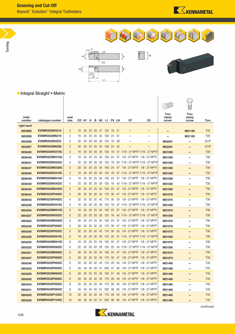
Grooving and Cut-Off
Beyond™ Evolution™ Integral Toolholders
Integral Straight • Metric
order number catalogue number
seat size CD H1 H B H2 L1 FS LH CF CS
Torx clamp screw
Torx clamp screw Torx
right hand
5953960 EVSMR2020K0216 2 16 20 20 20 27 125 19 31 — — — MS1160 T20
5953958 EVSMR2525M0216 2 16 25 25 25 32 150 24 31 — — — MS1160 T20
5953959 EVSMR2020K0222 2 22 20 20 20 29 125 19 38 — — MS2091 — 25 IP
5953957 EVSMR2525M0226 2 26 25 25 25 34 150 24 42 — — MS2091 — 25 IP
5939452 EVSMR2020K0316C 3 16 20 20 20 29 125 19 37 1/16 - 27 NPTF 1/16 - 27 NPTF MS1595 — T30
5939448 EVSMR2525M0316C 3 16 25 25 25 34 150 24 37 1/8 - 27 NPTF 1/8 - 27 NPTF MS1595 — T30
5939451 EVSMR2020K0322C 3 22 20 20 20 29 125 19 43 1/16 - 27 NPTF 1/16 - 27 NPTF MS1595 — T30
5939447 EVSMR2525M0326C 3 26 25 25 25 34 150 24 47 1/8 - 27 NPTF 1/8 - 27 NPTF MS1595 — T30
5939450 EVSMR2020K0416C 4 16 20 20 20 29 125 18 37 1/16 - 27 NPTF 1/16 - 27 NPTF MS1595 — T30
5939446 EVSMR2525M0416C 4 16 25 25 25 34 150 23 37 1/8 - 27 NPTF 1/8 - 27 NPTF MS1595 — T30
5939449 EVSMR2020K0422C 4 22 20 20 20 29 125 18 43 1/16 - 27 NPTF 1/16 - 27 NPTF MS1595 — T30
5939445 EVSMR2525M0426C 4 26 25 25 25 34 150 23 47 1/8 - 27 NPTF 1/8 - 27 NPTF MS1595 — T30
5939444 EVSMR3232P0426C 4 26 32 32 32 42 170 30 47 1/8 - 27 NPTF 1/8 - 27 NPTF MS1970 — T30
5939443 EVSMR3232P0432C 4 32 32 32 32 42 170 30 53 1/8 - 27 NPTF 1/8 - 27 NPTF MS1970 — T30
5954258 EVSMR2020K0516C 5 16 20 20 20 29 125 18 37 1/16 - 27 NPTF 1/16 - 27 NPTF MS1595 — T30
5954254 EVSMR2525M0516C 5 16 25 25 25 34 150 23 37 1/8 - 27 NPTF 1/8 - 27 NPTF MS1970 — T30
5954257 EVSMR2020K0522C 5 22 20 20 20 29 125 18 43 1/16 - 27 NPTF 1/16 - 27 NPTF MS1595 — T30
5954253 EVSMR2525M0526C 5 26 25 25 25 34 150 23 47 1/8 - 27 NPTF 1/8 - 27 NPTF MS1970 — T30
5954249 EVSMR3232P0526C 5 26 32 32 32 42 170 30 47 1/8 - 27 NPTF 1/8 - 27 NPTF MS1970 — T30
5954248 EVSMR3232P0532C 5 32 32 32 32 42 170 30 53 1/8 - 27 NPTF 1/8 - 27 NPTF MS1970 — T30
5954256 EVSMR2020K0616C 6 16 20 20 20 29 125 20 37 1/16 - 27 NPTF 1/16 - 27 NPTF MS1595 — T30
5954252 EVSMR2525M0616C 6 16 25 25 25 34 150 25 37 1/8 - 27 NPTF 1/8 - 27 NPTF MS1970 — T30
5954255 EVSMR2020K0622C 6 22 20 20 20 29 125 20 43 1/16 - 27 NPTF 1/16 - 27 NPTF MS1595 — T30
5954251 EVSMR2525M0626C 6 26 25 25 25 34 150 25 47 1/8 - 27 NPTF 1/8 - 27 NPTF MS1970 — T30
5954247 EVSMR3232P0626C 6 26 32 32 32 42 170 32 47 1/8 - 27 NPTF 1/8 - 27 NPTF MS1970 — T30
5954246 EVSMR3232P0632C 6 32 32 32 32 43 170 29 55 1/8 - 27 NPTF 1/8 - 27 NPTF MS1490 — T45
5954242 EVSMR4040P0640C 6 40 40 40 40 51 200 37 63 1/8 - 27 NPTF 1/8 - 27 NPTF MS1490 — T45
5954250 EVSMR2525M0826C 8 26 25 25 25 35 150 21 49 1/8 - 27 NPTF 1/8 - 27 NPTF MS1490 — T45
5954245 EVSMR3232P0826C 8 26 32 32 32 43 170 28 49 1/8 - 27 NPTF 1/8 - 27 NPTF MS1490 — T45
5954244 EVSMR3232P0832C 8 32 32 32 32 43 170 28 55 1/8 - 27 NPTF 1/8 - 27 NPTF MS1490 — T45
5954241 EVSMR4040P0840C 8 40 40 40 40 51 200 36 63 1/8 - 27 NPTF 1/8 - 27 NPTF MS1490 — T45
5954243 EVSMR3232P1032C 10 32 32 32 32 43 170 28 55 1/8 - 27 NPTF 1/8 - 27 NPTF MS1490 — T45
5954240 EVSMR4040P1040C 10 40 40 40 40 51 200 36 63 1/8 - 27 NPTF 1/8 - 27 NPTF MS1490 — T45
Turn
ing
A038_A039_KMT_Innovations_2016_Beyond_Evolution_Product_Brochure_038_039_EN_me.indd 38 7/28/15 1:16 PM
A39
L V i A038 A039 KMT I i 2016 B d E l i P d B h 038 039 EN J l92015448PM
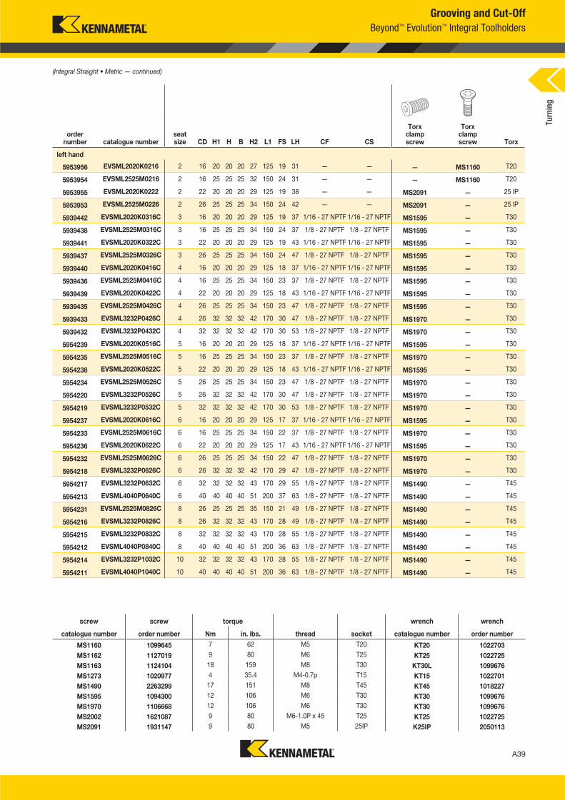
Grooving and Cut-Off
Beyond™ Evolution™ Integral Toolholders
order number catalogue number
seat size CD H1 H B H2 L1 FS LH CF CS
Torx clamp screw
Torx clamp screw Torx
left hand
5953956 EVSML2020K0216 2 16 20 20 20 27 125 19 31 — — — MS1160 T20
5953954 EVSML2525M0216 2 16 25 25 25 32 150 24 31 — — — MS1160 T20
5953955 EVSML2020K0222 2 22 20 20 20 29 125 19 38 — — MS2091 — 25 IP
5953953 EVSML2525M0226 2 26 25 25 25 34 150 24 42 — — MS2091 — 25 IP
5939442 EVSML2020K0316C 3 16 20 20 20 29 125 19 37 1/16 - 27 NPTF 1/16 - 27 NPTF MS1595 — T30
5939438 EVSML2525M0316C 3 16 25 25 25 34 150 24 37 1/8 - 27 NPTF 1/8 - 27 NPTF MS1595 — T30
5939441 EVSML2020K0322C 3 22 20 20 20 29 125 19 43 1/16 - 27 NPTF 1/16 - 27 NPTF MS1595 — T30
5939437 EVSML2525M0326C 3 26 25 25 25 34 150 24 47 1/8 - 27 NPTF 1/8 - 27 NPTF MS1595 — T30
5939440 EVSML2020K0416C 4 16 20 20 20 29 125 18 37 1/16 - 27 NPTF 1/16 - 27 NPTF MS1595 — T30
5939436 EVSML2525M0416C 4 16 25 25 25 34 150 23 37 1/8 - 27 NPTF 1/8 - 27 NPTF MS1595 — T30
5939439 EVSML2020K0422C 4 22 20 20 20 29 125 18 43 1/16 - 27 NPTF 1/16 - 27 NPTF MS1595 — T30
5939435 EVSML2525M0426C 4 26 25 25 25 34 150 23 47 1/8 - 27 NPTF 1/8 - 27 NPTF MS1595 — T30
5939433 EVSML3232P0426C 4 26 32 32 32 42 170 30 47 1/8 - 27 NPTF 1/8 - 27 NPTF MS1970 — T30
5939432 EVSML3232P0432C 4 32 32 32 32 42 170 30 53 1/8 - 27 NPTF 1/8 - 27 NPTF MS1970 — T30
5954239 EVSML2020K0516C 5 16 20 20 20 29 125 18 37 1/16 - 27 NPTF 1/16 - 27 NPTF MS1595 — T30
5954235 EVSML2525M0516C 5 16 25 25 25 34 150 23 37 1/8 - 27 NPTF 1/8 - 27 NPTF MS1970 — T30
5954238 EVSML2020K0522C 5 22 20 20 20 29 125 18 43 1/16 - 27 NPTF 1/16 - 27 NPTF MS1595 — T30
5954234 EVSML2525M0526C 5 26 25 25 25 34 150 23 47 1/8 - 27 NPTF 1/8 - 27 NPTF MS1970 — T30
5954220 EVSML3232P0526C 5 26 32 32 32 42 170 30 47 1/8 - 27 NPTF 1/8 - 27 NPTF MS1970 — T30
5954219 EVSML3232P0532C 5 32 32 32 32 42 170 30 53 1/8 - 27 NPTF 1/8 - 27 NPTF MS1970 — T30
5954237 EVSML2020K0616C 6 16 20 20 20 29 125 17 37 1/16 - 27 NPTF 1/16 - 27 NPTF MS1595 — T30
5954233 EVSML2525M0616C 6 16 25 25 25 34 150 22 37 1/8 - 27 NPTF 1/8 - 27 NPTF MS1970 — T30
5954236 EVSML2020K0622C 6 22 20 20 20 29 125 17 43 1/16 - 27 NPTF 1/16 - 27 NPTF MS1595 — T30
5954232 EVSML2525M0626C 6 26 25 25 25 34 150 22 47 1/8 - 27 NPTF 1/8 - 27 NPTF MS1970 — T30
5954218 EVSML3232P0626C 6 26 32 32 32 42 170 29 47 1/8 - 27 NPTF 1/8 - 27 NPTF MS1970 — T30
5954217 EVSML3232P0632C 6 32 32 32 32 43 170 29 55 1/8 - 27 NPTF 1/8 - 27 NPTF MS1490 — T45
5954213 EVSML4040P0640C 6 40 40 40 40 51 200 37 63 1/8 - 27 NPTF 1/8 - 27 NPTF MS1490 — T45
5954231 EVSML2525M0826C 8 26 25 25 25 35 150 21 49 1/8 - 27 NPTF 1/8 - 27 NPTF MS1490 — T45
5954216 EVSML3232P0826C 8 26 32 32 32 43 170 28 49 1/8 - 27 NPTF 1/8 - 27 NPTF MS1490 — T45
5954215 EVSML3232P0832C 8 32 32 32 32 43 170 28 55 1/8 - 27 NPTF 1/8 - 27 NPTF MS1490 — T45
5954212 EVSML4040P0840C 8 40 40 40 40 51 200 36 63 1/8 - 27 NPTF 1/8 - 27 NPTF MS1490 — T45
5954214 EVSML3232P1032C 10 32 32 32 32 43 170 28 55 1/8 - 27 NPTF 1/8 - 27 NPTF MS1490 — T45
5954211 EVSML4040P1040C 10 40 40 40 40 51 200 36 63 1/8 - 27 NPTF 1/8 - 27 NPTF MS1490 — T45
(Integral Straight • Metric — continued)
screw screw torque wrench wrench
catalogue number order number Nm in. lbs. thread socket catalogue number order number
MS1160 1099645 7 62 M5 T20 KT20 1022703
MS1162 1127019 9 80 M6 T25 KT25 1022725
MS1163 1124104 18 159 M8 T30 KT30L 1099676
MS1273 1020977 4 35.4 M4-0.7p T15 KT15 1022701
MS1490 2263299 17 151 M8 T45 KT45 1018227
MS1595 1094300 12 106 M6 T30 KT30 1099676
MS1970 1106668 12 106 M6 T30 KT30 1099676
MS2002 1621087 9 80 M6-1.0P x 45 T25 KT25 1022725
MS2091 1931147 9 80 M5 25IP K25IP 2050113
Turn
ing
A038_A039_KMT_Innovations_2016_Beyond_Evolution_Product_Brochure_038_039_EN_me.indd 39 7/28/15 1:16 PM
A40
L V i A040 A041 KMT I i 2016 B d E l i P d B h 040 041 EN J l 920154 48PM
Grooving and Cut-Off
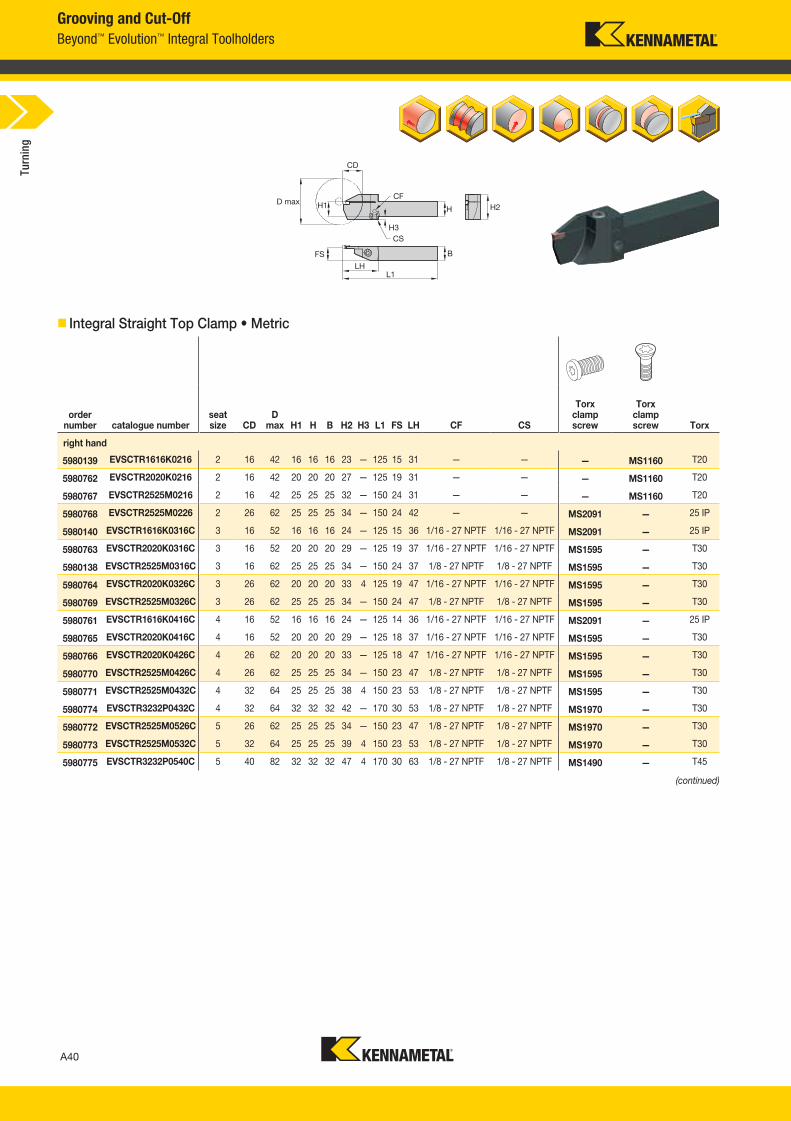
Beyond™ Evolution™ Integral Toolholders
Integral Straight Top Clamp • Metric
order number catalogue number
seat size CD
D max H1 H B H2 H3 L1 FS LH CF CS
Torx clamp screw
Torx clamp screw Torx
right hand
5980139 EVSCTR1616K0216 2 16 42 16 16 16 23 — 125 15 31 — — — MS1160 T20
5980762 EVSCTR2020K0216 2 16 42 20 20 20 27 — 125 19 31 — — — MS1160 T20
5980767 EVSCTR2525M0216 2 16 42 25 25 25 32 — 150 24 31 — — — MS1160 T20
5980768 EVSCTR2525M0226 2 26 62 25 25 25 34 — 150 24 42 — — MS2091 — 25 IP
5980140 EVSCTR1616K0316C 3 16 52 16 16 16 24 — 125 15 36 1/16 - 27 NPTF 1/16 - 27 NPTF MS2091 — 25 IP
5980763 EVSCTR2020K0316C 3 16 52 20 20 20 29 — 125 19 37 1/16 - 27 NPTF 1/16 - 27 NPTF MS1595 — T30
5980138 EVSCTR2525M0316C 3 16 62 25 25 25 34 — 150 24 37 1/8 - 27 NPTF 1/8 - 27 NPTF MS1595 — T30
5980764 EVSCTR2020K0326C 3 26 62 20 20 20 33 4 125 19 47 1/16 - 27 NPTF 1/16 - 27 NPTF MS1595 — T30
5980769 EVSCTR2525M0326C 3 26 62 25 25 25 34 — 150 24 47 1/8 - 27 NPTF 1/8 - 27 NPTF MS1595 — T30
5980761 EVSCTR1616K0416C 4 16 52 16 16 16 24 — 125 14 36 1/16 - 27 NPTF 1/16 - 27 NPTF MS2091 — 25 IP
5980765 EVSCTR2020K0416C 4 16 52 20 20 20 29 — 125 18 37 1/16 - 27 NPTF 1/16 - 27 NPTF MS1595 — T30
5980766 EVSCTR2020K0426C 4 26 62 20 20 20 33 — 125 18 47 1/16 - 27 NPTF 1/16 - 27 NPTF MS1595 — T30
5980770 EVSCTR2525M0426C 4 26 62 25 25 25 34 — 150 23 47 1/8 - 27 NPTF 1/8 - 27 NPTF MS1595 — T30
5980771 EVSCTR2525M0432C 4 32 64 25 25 25 38 4 150 23 53 1/8 - 27 NPTF 1/8 - 27 NPTF MS1595 — T30
5980774 EVSCTR3232P0432C 4 32 64 32 32 32 42 — 170 30 53 1/8 - 27 NPTF 1/8 - 27 NPTF MS1970 — T30
5980772 EVSCTR2525M0526C 5 26 62 25 25 25 34 — 150 23 47 1/8 - 27 NPTF 1/8 - 27 NPTF MS1970 — T30
5980773 EVSCTR2525M0532C 5 32 64 25 25 25 39 4 150 23 53 1/8 - 27 NPTF 1/8 - 27 NPTF MS1970 — T30
5980775 EVSCTR3232P0540C 5 40 82 32 32 32 47 4 170 30 63 1/8 - 27 NPTF 1/8 - 27 NPTF MS1490 — T45
(continued)
Turn
ing
A040_A041_KMT_Innovations_2016_Beyond_Evolution_Product_Brochure_040_041_EN_me.indd 40 7/28/15 1:16 PM
A41
L V i A040 A041 KMT I i 2016 B d E l i P d B h 040 041 EN J l92015448PM
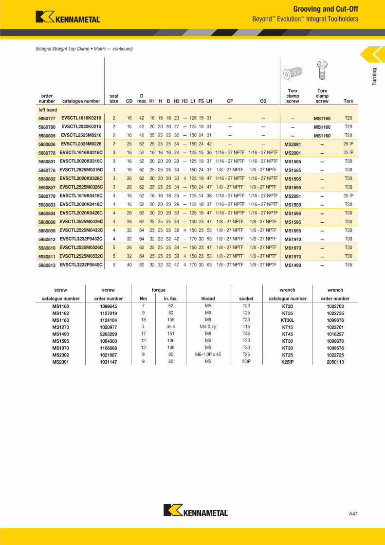
Grooving and Cut-Off
Beyond™ Evolution™ Integral Toolholders
order number catalogue number
seat size CD
D max H1 H B H2 H3 L1 FS LH CF CS
Torx clamp screw
Torx clamp screw Torx
left hand
5980777 EVSCTL1616K0216 2 16 42 16 16 16 23 — 125 15 31 — — — MS1160 T20
5980780 EVSCTL2020K0216 2 16 42 20 20 20 27 — 125 19 31 — — — MS1160 T20
5980805 EVSCTL2525M0216 2 16 42 25 25 25 32 — 150 24 31 — — — MS1160 T20
5980806 EVSCTL2525M0226 2 26 62 25 25 25 34 — 150 24 42 — — MS2091 — 25 IP
5980778 EVSCTL1616K0316C 3 16 52 16 16 16 24 — 125 15 36 1/16 - 27 NPTF 1/16 - 27 NPTF MS2091 — 25 IP
5980801 EVSCTL2020K0316C 3 16 52 20 20 20 29 — 125 19 37 1/16 - 27 NPTF 1/16 - 27 NPTF MS1595 — T30
5980776 EVSCTL2525M0316C 3 16 62 25 25 25 34 — 150 24 37 1/8 - 27 NPTF 1/8 - 27 NPTF MS1595 — T30
5980802 EVSCTL2020K0326C 3 26 62 20 20 20 33 4 125 19 47 1/16 - 27 NPTF 1/16 - 27 NPTF MS1595 — T30
5980807 EVSCTL2525M0326C 3 26 62 25 25 25 34 — 150 24 47 1/8 - 27 NPTF 1/8 - 27 NPTF MS1595 — T30
5980779 EVSCTL1616K0416C 4 16 52 16 16 16 24 — 125 14 36 1/16 - 27 NPTF 1/16 - 27 NPTF MS2091 — 25 IP
5980803 EVSCTL2020K0416C 4 16 52 20 20 20 29 — 125 18 37 1/16 - 27 NPTF 1/16 - 27 NPTF MS1595 — T30
5980804 EVSCTL2020K0426C 4 26 62 20 20 20 33 — 125 18 47 1/16 - 27 NPTF 1/16 - 27 NPTF MS1595 — T30
5980808 EVSCTL2525M0426C 4 26 62 25 25 25 34 — 150 23 47 1/8 - 27 NPTF 1/8 - 27 NPTF MS1595 — T30
5980809 EVSCTL2525M0432C 4 32 64 25 25 25 38 4 150 23 53 1/8 - 27 NPTF 1/8 - 27 NPTF MS1595 — T30
5980812 EVSCTL3232P0432C 4 32 64 32 32 32 42 — 170 30 53 1/8 - 27 NPTF 1/8 - 27 NPTF MS1970 — T30
5980810 EVSCTL2525M0526C 5 26 62 25 25 25 34 — 150 23 47 1/8 - 27 NPTF 1/8 - 27 NPTF MS1970 — T30
5980811 EVSCTL2525M0532C 5 32 64 25 25 25 39 4 150 23 53 1/8 - 27 NPTF 1/8 - 27 NPTF MS1970 — T30
5980813 EVSCTL3232P0540C 5 40 82 32 32 32 47 4 170 30 63 1/8 - 27 NPTF 1/8 - 27 NPTF MS1490 — T45
(Integral Straight Top Clamp • Metric — continued)
screw screw torque wrench wrench
catalogue number order number Nm in. lbs. thread socket catalogue number order number
MS1160 1099645 7 62 M5 T20 KT20 1022703
MS1162 1127019 9 80 M6 T25 KT25 1022725
MS1163 1124104 18 159 M8 T30 KT30L 1099676
MS1273 1020977 4 35.4 M4-0.7p T15 KT15 1022701
MS1490 2263299 17 151 M8 T45 KT45 1018227
MS1595 1094300 12 106 M6 T30 KT30 1099676
MS1970 1106668 12 106 M6 T30 KT30 1099676
MS2002 1621087 9 80 M6-1.0P x 45 T25 KT25 1022725
MS2091 1931147 9 80 M5 25IP K25IP 2050113
Turn
ing
A040_A041_KMT_Innovations_2016_Beyond_Evolution_Product_Brochure_040_041_EN_me.indd 41 7/28/15 1:16 PM
A42
L V i A042 A043 KMT I i 2016 B d E l i P d B h 042 043 EN J l 920154 48PM
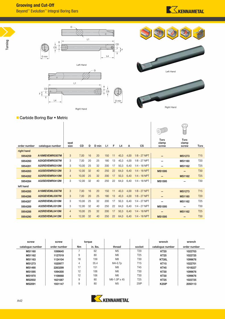
Grooving and Cut-Off
Beyond™ Evolution™ Integral Boring Bars
Carbide Boring Bar • Metric
order number catalogue numberseat size CD D D min L1 F L4 A CS
Torx clamp screw
Torx clamp screw Torx
right hand
5954259 A16MEVEMR0307M 3 7,00 16 20 150 11 40,3 4,00 1/8 - 27 NPT — MS1273 T15
5954260 A20QEVEMR0307M 3 7,00 20 25 180 13 40,3 4,00 1/8 - 27 NPT — MS1160 T20
5954281 A25REVEMR0310M 3 10,00 25 32 200 17 50,3 6,40 1/4 - 18 NPT — MS1162 T25
5954283 A32SEVEMR0312M 3 12,00 32 40 250 22 64,0 6,40 1/4 - 18 NPT MS1595 — T30
5954282 A25REVEMR0410M 4 10,00 25 32 200 17 50,3 6,40 1/4 - 18 NPT — MS1162 T25
5954284 A32SEVEMR0412M 3 12,00 32 40 250 22 64,0 6,40 1/4 - 18 NPT MS1595 — T30
left hand
5954285 A16MEVEML0307M 3 7,00 16 20 150 11 40,3 4,00 1/8 - 27 NPT — MS1273 T15
5954286 A20QEVEML0307M 3 7,00 20 25 180 13 40,3 4,00 1/8 - 27 NPT — MS1160 T20
5954287 A25REVEML0310M 3 10,00 25 32 200 17 50,3 6,40 1/4 - 27 NPT — MS1162 T25
5954289 A32SEVEML0312M 3 12,00 32 40 250 22 64,0 6,40 1/4 - 27 NPT MS1595 — T30
5954288 A25REVEML0410M 4 10,00 25 32 200 17 50,3 6,40 1/4 - 18 NPT — MS1162 T25
5954290 A32SEVEML0412M 4 12,00 32 40 250 22 64,0 6,40 1/4 - 18 NPT MS1595 — T30
Right Hand
Left Hand
Right Hand
Left Hand
screw screw torque wrench wrench
catalogue number order number Nm in. lbs. thread socket catalogue number order number
MS1160 1099645 7 62 M5 T20 KT20 1022703
MS1162 1127019 9 80 M6 T25 KT25 1022725
MS1163 1124104 18 159 M8 T30 KT30L 1099676
MS1273 1020977 4 35.4 M4-0.7p T15 KT15 1022701
MS1490 2263299 17 151 M8 T45 KT45 1018227
MS1595 1094300 12 106 M6 T30 KT30 1099676
MS1970 1106668 12 106 M6 T30 KT30 1099676
MS2002 1621087 9 80 M6-1.0P x 45 T25 KT25 1022725
MS2091 1931147 9 80 M5 25IP K25IP 2050113
Turn
ing
A042_A043_KMT_Innovations_2016_Beyond_Evolution_Product_Brochure_042_043_EN_me.indd 42 7/28/15 1:16 PM
A43
L V i A042 A043 KMT I i 2016 B d E l i P d B h 042 043 EN J l92015448PM
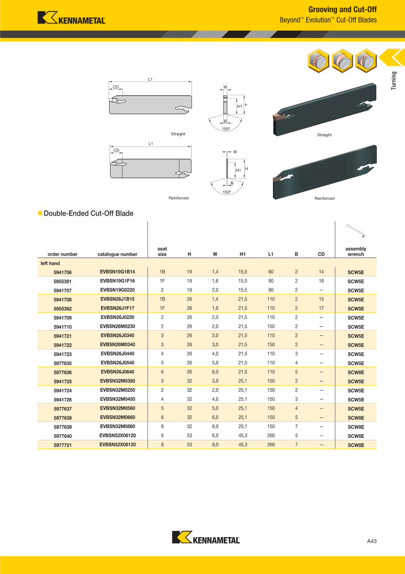
Grooving and Cut-Off
Beyond™ Evolution™ Cut-Off Blades
Double-Ended Cut-Off Blade
order number catalogue numberseat size H W H1 L1 B CD
assembly wrench
left hand
5941706 EVBSN19G1B14 1B 19 1,4 15,5 90 2 14 SCW5E
5955391 EVBSN19G1F16 1F 19 1,6 15,5 90 2 16 SCW5E
5941707 EVBSN19G0220 2 19 2,0 15,5 90 2 — SCW5E
5941708 EVBSN26J1B15 1B 26 1,4 21,5 110 2 15 SCW5E
5955392 EVBSN26J1F17 1F 26 1,6 21,5 110 2 17 SCW5E
5941709 EVBSN26J0230 2 26 2,0 21,5 110 2 — SCW5E
5941710 EVBSN26M0230 2 26 2,0 21,5 150 2 — SCW5E
5941721 EVBSN26J0340 3 26 3,0 21,5 110 2 — SCW5E
5941722 EVBSN26M0340 3 26 3,0 21,5 150 2 — SCW5E
5941723 EVBSN26J0440 4 26 4,0 21,5 110 3 — SCW5E
5977635 EVBSN26J0540 5 26 5,0 21,5 110 4 — SCW5E
5977636 EVBSN26J0640 6 26 6,0 21,5 110 5 — SCW8E
5941725 EVBSN32M0350 3 32 3,0 25,1 150 2 — SCW5E
5941724 EVBSN32M0250 2 32 2,0 25,1 150 2 — SCW5E
5941726 EVBSN32M0450 4 32 4,0 25,1 150 3 — SCW5E
5977637 EVBSN32M0560 5 32 5,0 25,1 150 4 — SCW5E
5977638 EVBSN32M0660 6 32 6,0 25,1 150 5 — SCW8E
5977639 EVBSN32M0860 8 32 8,0 25,1 150 7 — SCW8E
5977640 EVBSN52X06120 6 53 6,0 45,3 260 5 — SCW8E
5977721 EVBSN52X08120 8 53 8,0 45,3 260 7 — SCW8E
Reinforced
Straight
Reinforced
Straight
Turn
ing
A042_A043_KMT_Innovations_2016_Beyond_Evolution_Product_Brochure_042_043_EN_me.indd 43 7/28/15 1:16 PM
A44
L V i A044 A045 KMT I i 2016 B d E l i P d B h 044 045 EN J l 920154 47PM
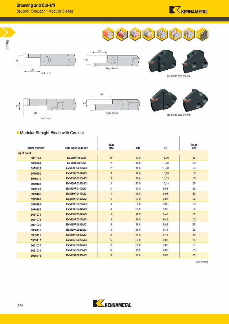
Grooving and Cut-Off
Beyond™ Evolution™ Modular Blades
Modular Straight Blade with Coolant
order number catalogue numberseat size CD FS
blade size
right hand
6031041 EVM50R1F12M 1F 12,0 11,00 50
6030969 EVM50R0212M 2 12,0 10,88 50
5955423 EVM50R0216MC 2 16,0 10,88 50
5979200 EVM50R0312MC 3 12,0 10,43 50
5979010 EVM50R0316MC 3 16,0 10,43 50
5979181 EVM50R0322MC 3 22,0 10,43 50
5979201 EVM50R0412MC 4 12,0 9,93 50
5979182 EVM50R0416MC 4 16,0 9,93 50
5979183 EVM50R0422MC 4 22,0 9,93 50
5979198 EVM50R0426MC 4 26,0 9,93 50
5979184 EVM50R0432MC 4 32,0 9,93 50
6031031 EVM50R0512MC 5 12,0 9,43 50
6031033 EVM50R0516MC 5 16,0 9,43 50
6031035 EVM65R0616MC 5 16,0 9,88 65
5955415 EVM50R0526MC 5 26,0 9,43 50
5955416 EVM50R0532MC 5 32,0 9,43 50
5955417 EVM65R0626MC 6 26,0 9,88 65
6031037 EVM65R0632MC 6 32,0 9,88 65
6031039 EVM65R0816MC 8 16,0 9,00 65
5955418 EVM65R0826MC 8 26,0 9,00 65
(continued)
Right Hand
Left Hand
Right Hand
Left Hand
(50 blade size shown)
(65 blade size shown)
Turn
ing
A044_A045_KMT_Innovations_2016_Beyond_Evolution_Product_Brochure_044_045_EN_me.indd 44 7/28/15 1:16 PM
A45
L V i A044 A045 KMT I i 2016 B d E l i P d B h 044 045 EN J l92015447PM
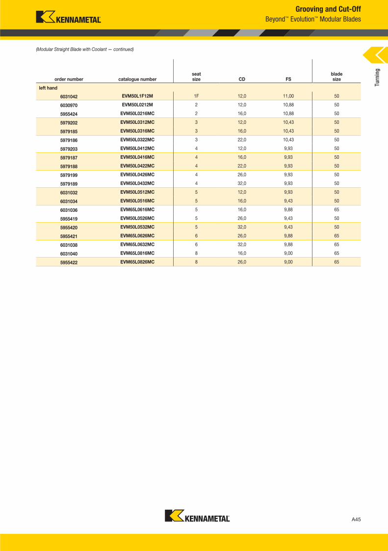
Grooving and Cut-Off
Beyond™ Evolution™ Modular Blades
order number catalogue numberseat size CD FS
blade size
left hand
6031042 EVM50L1F12M 1F 12,0 11,00 50
6030970 EVM50L0212M 2 12,0 10,88 50
5955424 EVM50L0216MC 2 16,0 10,88 50
5979202 EVM50L0312MC 3 12,0 10,43 50
5979185 EVM50L0316MC 3 16,0 10,43 50
5979186 EVM50L0322MC 3 22,0 10,43 50
5979203 EVM50L0412MC 4 12,0 9,93 50
5979187 EVM50L0416MC 4 16,0 9,93 50
5979188 EVM50L0422MC 4 22,0 9,93 50
5979199 EVM50L0426MC 4 26,0 9,93 50
5979189 EVM50L0432MC 4 32,0 9,93 50
6031032 EVM50L0512MC 5 12,0 9,93 50
6031034 EVM50L0516MC 5 16,0 9,43 50
6031036 EVM65L0616MC 5 16,0 9,88 65
5955419 EVM50L0526MC 5 26,0 9,43 50
5955420 EVM50L0532MC 5 32,0 9,43 50
5955421 EVM65L0626MC 6 26,0 9,88 65
6031038 EVM65L0632MC 6 32,0 9,88 65
6031040 EVM65L0816MC 8 16,0 9,00 65
5955422 EVM65L0826MC 8 26,0 9,00 65
(Modular Straight Blade with Coolant — continued)
Turn
ing
A044_A045_KMT_Innovations_2016_Beyond_Evolution_Product_Brochure_044_045_EN_me.indd 45 7/28/15 1:16 PM
A46
L V i A046 A047 KMT I i 2016 B d E l i P d B h 046 047 EN J l 920154 47PM
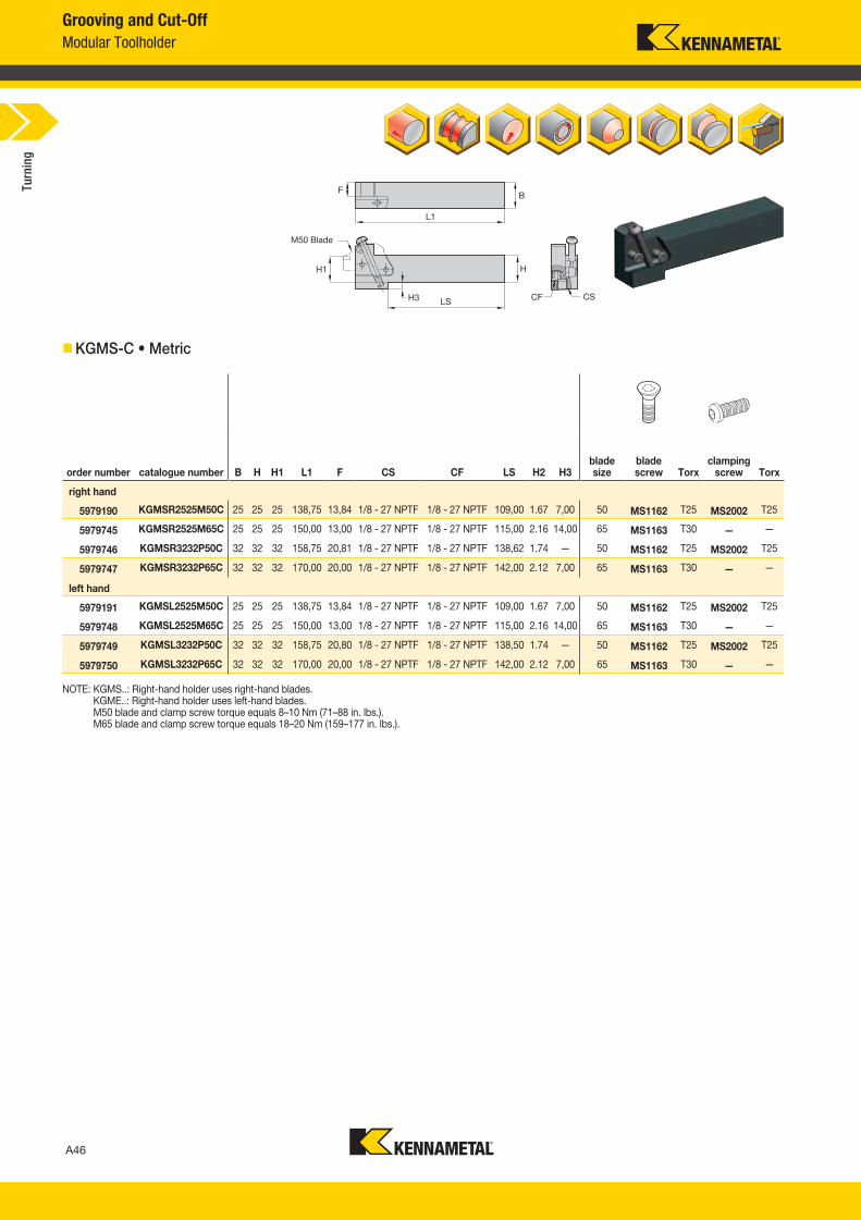
Grooving and Cut-Off
Modular Toolholder
KGMS-C • Metric
order number catalogue number B H H1 L1 F CS CF LS H2 H3blade size
blade screw Torx
clampingscrew Torx
right hand
5979190 KGMSR2525M50C 25 25 25 138,75 13,84 1/8 - 27 NPTF 1/8 - 27 NPTF 109,00 1.67 7,00 50 MS1162 T25 MS2002 T25
5979745 KGMSR2525M65C 25 25 25 150,00 13,00 1/8 - 27 NPTF 1/8 - 27 NPTF 115,00 2.16 14,00 65 MS1163 T30 — —
5979746 KGMSR3232P50C 32 32 32 158,75 20,81 1/8 - 27 NPTF 1/8 - 27 NPTF 138,62 1.74 — 50 MS1162 T25 MS2002 T25
5979747 KGMSR3232P65C 32 32 32 170,00 20,00 1/8 - 27 NPTF 1/8 - 27 NPTF 142,00 2.12 7,00 65 MS1163 T30 — —
left hand
5979191 KGMSL2525M50C 25 25 25 138,75 13,84 1/8 - 27 NPTF 1/8 - 27 NPTF 109,00 1.67 7,00 50 MS1162 T25 MS2002 T25
5979748 KGMSL2525M65C 25 25 25 150,00 13,00 1/8 - 27 NPTF 1/8 - 27 NPTF 115,00 2.16 14,00 65 MS1163 T30 — —
5979749 KGMSL3232P50C 32 32 32 158,75 20,80 1/8 - 27 NPTF 1/8 - 27 NPTF 138,50 1.74 — 50 MS1162 T25 MS2002 T25
5979750 KGMSL3232P65C 32 32 32 170,00 20,00 1/8 - 27 NPTF 1/8 - 27 NPTF 142,00 2.12 7,00 65 MS1163 T30 — —
NOTE: KGMS..: Right-hand holder uses right-hand blades. KGME..: Right-hand holder uses left-hand blades. M50 blade and clamp screw torque equals 8–10 Nm (71–88 in. lbs.). M65 blade and clamp screw torque equals 18–20 Nm (159–177 in. lbs.).
M50 Blade
Turn
ing
A046_A047_KMT_Innovations_2016_Beyond_Evolution_Product_Brochure_046_047_EN_me.indd 46 7/28/15 1:16 PM
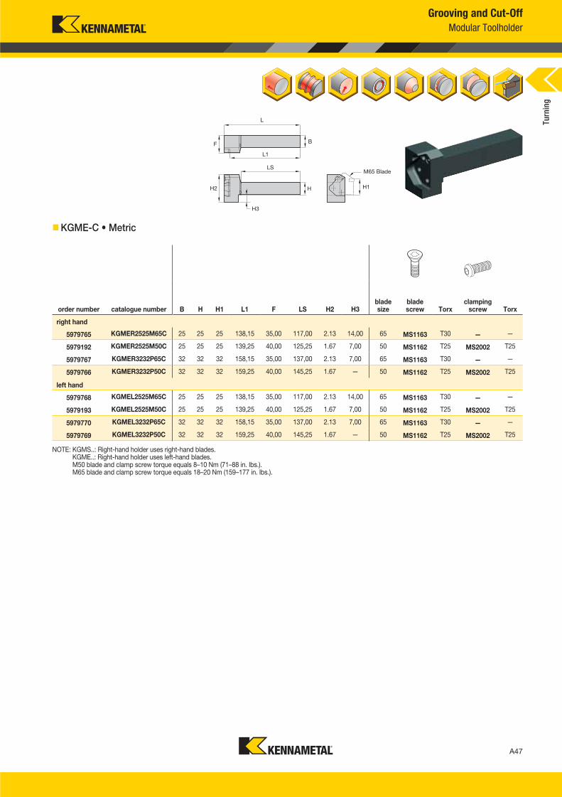
A47
L V i A046 A047 KMT I i 2016 B d E l i P d B h 046 047 EN J l92015447PM
Grooving and Cut-Off
Modular Toolholder
KGME-C • Metric
NOTE: KGMS..: Right-hand holder uses right-hand blades. KGME..: Right-hand holder uses left-hand blades. M50 blade and clamp screw torque equals 8–10 Nm (71–88 in. lbs.). M65 blade and clamp screw torque equals 18–20 Nm (159–177 in. lbs.).
order number catalogue number B H H1 L1 F LS H2 H3blade size
blade screw Torx
clampingscrew Torx
right hand
5979765 KGMER2525M65C 25 25 25 138,15 35,00 117,00 2.13 14,00 65 MS1163 T30 — —
5979192 KGMER2525M50C 25 25 25 139,25 40,00 125,25 1.67 7,00 50 MS1162 T25 MS2002 T25
5979767 KGMER3232P65C 32 32 32 158,15 35,00 137,00 2.13 7,00 65 MS1163 T30 — —
5979766 KGMER3232P50C 32 32 32 159,25 40,00 145,25 1.67 — 50 MS1162 T25 MS2002 T25
left hand
5979768 KGMEL2525M65C 25 25 25 138,15 35,00 117,00 2.13 14,00 65 MS1163 T30 — —
5979193 KGMEL2525M50C 25 25 25 139,25 40,00 125,25 1.67 7,00 50 MS1162 T25 MS2002 T25
5979770 KGMEL3232P65C 32 32 32 158,15 35,00 137,00 2.13 7,00 65 MS1163 T30 — —
5979769 KGMEL3232P50C 32 32 32 159,25 40,00 145,25 1.67 — 50 MS1162 T25 MS2002 T25
M65 Blade
Turn
ing
A046_A047_KMT_Innovations_2016_Beyond_Evolution_Product_Brochure_046_047_EN_me.indd 47 7/28/15 1:16 PM
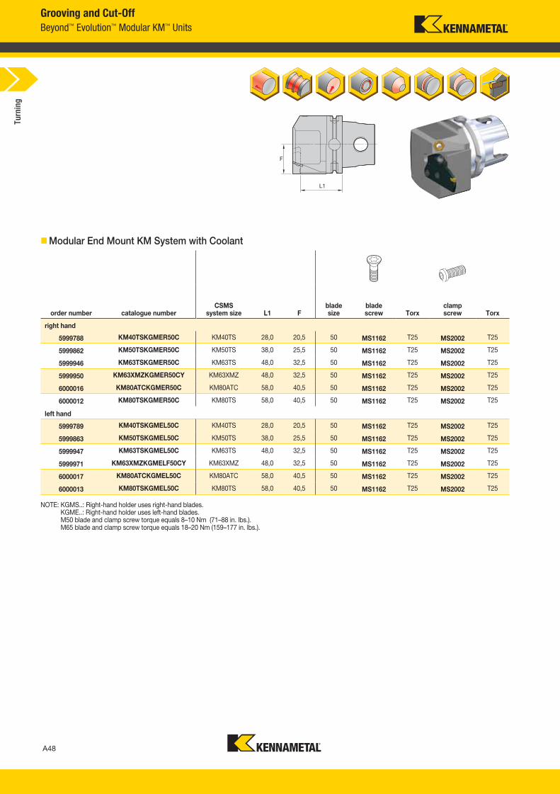
A48
L V i A048 A049 KMT I i 2016 B d E l i P d B h 048 049 EN J l 920154 47PM
Grooving and Cut-Off
Beyond™ Evolution™ Modular KM™ Units
Modular End Mount KM System with Coolant
order number catalogue numberCSMS
system size L1 Fblade size
blade screw Torx
clampscrew Torx
right hand
5999788 KM40TSKGMER50C KM40TS 28,0 20,5 50 MS1162 T25 MS2002 T25
5999862 KM50TSKGMER50C KM50TS 38,0 25,5 50 MS1162 T25 MS2002 T25
5999946 KM63TSKGMER50C KM63TS 48,0 32,5 50 MS1162 T25 MS2002 T25
5999950 KM63XMZKGMER50CY KM63XMZ 48,0 32,5 50 MS1162 T25 MS2002 T25
6000016 KM80ATCKGMER50C KM80ATC 58,0 40,5 50 MS1162 T25 MS2002 T25
6000012 KM80TSKGMER50C KM80TS 58,0 40,5 50 MS1162 T25 MS2002 T25
left hand
5999789 KM40TSKGMEL50C KM40TS 28,0 20,5 50 MS1162 T25 MS2002 T25
5999863 KM50TSKGMEL50C KM50TS 38,0 25,5 50 MS1162 T25 MS2002 T25
5999947 KM63TSKGMEL50C KM63TS 48,0 32,5 50 MS1162 T25 MS2002 T25
5999971 KM63XMZKGMELF50CY KM63XMZ 48,0 32,5 50 MS1162 T25 MS2002 T25
6000017 KM80ATCKGMEL50C KM80ATC 58,0 40,5 50 MS1162 T25 MS2002 T25
6000013 KM80TSKGMEL50C KM80TS 58,0 40,5 50 MS1162 T25 MS2002 T25
NOTE: KGMS..: Right-hand holder uses right-hand blades. KGME..: Right-hand holder uses left-hand blades. M50 blade and clamp screw torque equals 8–10 Nm (71–88 in. lbs.). M65 blade and clamp screw torque equals 18–20 Nm (159–177 in. lbs.).
Turn
ing
A048_A049_KMT_Innovations_2016_Beyond_Evolution_Product_Brochure_048_049_EN_me.indd 48 7/28/15 1:17 PM
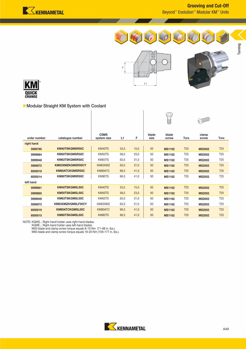
A49
L V i A048 A049 KMT I i 2016 B d E l i P d B h 048 049 EN J l92015447PM
Grooving and Cut-Off
Beyond™ Evolution™ Modular KM™ Units
Modular Straight KM System with Coolant
order number catalogue numberCSMS
system size L1 Fblade size
blade screw Torx
clampscrew Torx
right hand
5999790 KM40TSKGMSR50C KM40TS 53,5 15,0 50 MS1162 T25 MS2002 T25
5999864 KM50TSKGMSR50C KM50TS 58,5 23,0 50 MS1162 T25 MS2002 T25
5999948 KM63TSKGMSR50C KM63TS 63,5 31,0 50 MS1162 T25 MS2002 T25
5999972 KM63XMZKGMSR50CY KM63XMZ 63,5 31,0 50 MS1162 T25 MS2002 T25
6000018 KM80ATCKGMSR50C KM80ATC 66,5 41,0 50 MS1162 T25 MS2002 T25
6000014 KM80TSKGMSR50C KM80TS 66,5 41,0 50 MS1162 T25 MS2002 T25
left hand
5999861 KM40TSKGMSL50C KM40TS 53,5 15,0 50 MS1162 T25 MS2002 T25
5999865 KM50TSKGMSL50C KM50TS 58,5 23,0 50 MS1162 T25 MS2002 T25
5999949 KM63TSKGMSL50C KM63TS 63,5 31,0 50 MS1162 T25 MS2002 T25
5999973 KM63XMZKGMSLF50CY KM63XMZ 63,5 31,0 50 MS1162 T25 MS2002 T25
6000019 KM80ATCKGMSL50C KM80ATC 66,5 41,0 50 MS1162 T25 MS2002 T25
6000015 KM80TSKGMSL50C KM80TS 66,5 41,0 50 MS1162 T25 MS2002 T25
NOTE: KGMS..: Right-hand holder uses right-hand blades. KGME..: Right-hand holder uses left-hand blades. M50 blade and clamp screw torque equals 8–10 Nm (71–88 in. lbs.). M65 blade and clamp screw torque equals 18–20 Nm (159–177 in. lbs.).
Turn
ing
A048_A049_KMT_Innovations_2016_Beyond_Evolution_Product_Brochure_048_049_EN_me.indd 49 7/28/15 1:17 PM
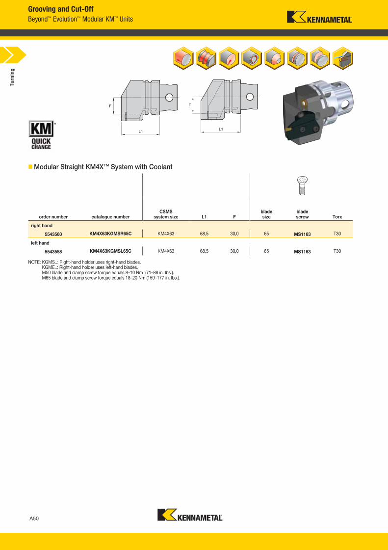
A50
L V i A050 A051 KMT I i 2016 B d E l i P d B h 050 051 EN J l 920154 47PM
Grooving and Cut-Off
Beyond™ Evolution™ Modular KM™ Units
Modular Straight KM4X™ System with Coolant
order number catalogue numberCSMS
system size L1 Fblade size
blade screw Torx
right hand
5543560 KM4X63KGMSR65C KM4X63 68,5 30,0 65 MS1163 T30
left hand
5543558 KM4X63KGMSL65C KM4X63 68,5 30,0 65 MS1163 T30
NOTE: KGMS..: Right-hand holder uses right-hand blades. KGME..: Right-hand holder uses left-hand blades. M50 blade and clamp screw torque equals 8–10 Nm (71–88 in. lbs.). M65 blade and clamp screw torque equals 18–20 Nm (159–177 in. lbs.).
Turn
ing
A050_A051_KMT_Innovations_2016_Beyond_Evolution_Product_Brochure_050_051_EN_me.indd 50 7/28/15 1:17 PM
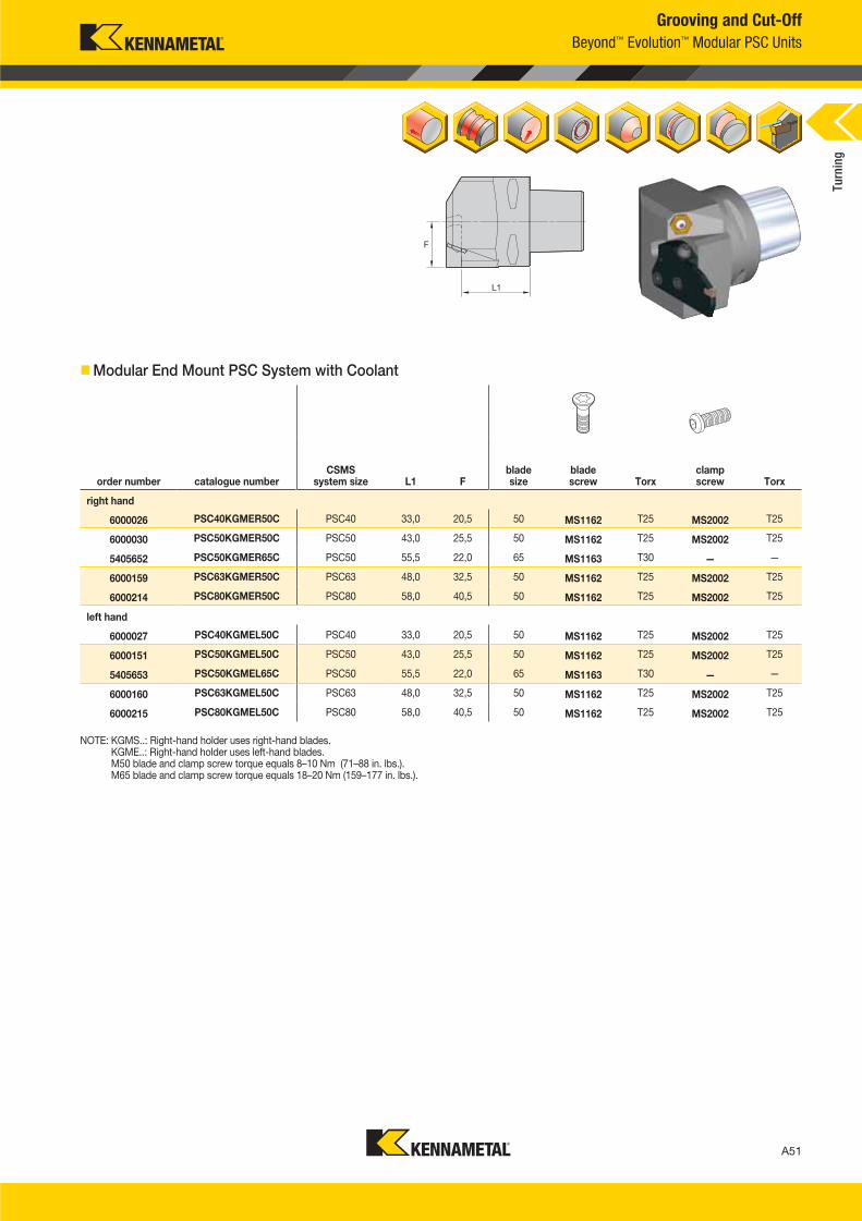
A51
L V i A050 A051 KMT I i 2016 B d E l i P d B h 050 051 EN J l92015447PM
NOTE: KGMS..: Right-hand holder uses right-hand blades. KGME..: Right-hand holder uses left-hand blades. M50 blade and clamp screw torque equals 8–10 Nm (71–88 in. lbs.). M65 blade and clamp screw torque equals 18–20 Nm (159–177 in. lbs.).
Grooving and Cut-Off
Beyond™ Evolution™ Modular PSC Units
Modular End Mount PSC System with Coolant
order number catalogue numberCSMS
system size L1 Fblade size
blade screw Torx
clampscrew Torx
right hand
6000026 PSC40KGMER50C PSC40 33,0 20,5 50 MS1162 T25 MS2002 T25
6000030 PSC50KGMER50C PSC50 43,0 25,5 50 MS1162 T25 MS2002 T25
5405652 PSC50KGMER65C PSC50 55,5 22,0 65 MS1163 T30 — —
6000159 PSC63KGMER50C PSC63 48,0 32,5 50 MS1162 T25 MS2002 T25
6000214 PSC80KGMER50C PSC80 58,0 40,5 50 MS1162 T25 MS2002 T25
left hand
6000027 PSC40KGMEL50C PSC40 33,0 20,5 50 MS1162 T25 MS2002 T25
6000151 PSC50KGMEL50C PSC50 43,0 25,5 50 MS1162 T25 MS2002 T25
5405653 PSC50KGMEL65C PSC50 55,5 22,0 65 MS1163 T30 — —
6000160 PSC63KGMEL50C PSC63 48,0 32,5 50 MS1162 T25 MS2002 T25
6000215 PSC80KGMEL50C PSC80 58,0 40,5 50 MS1162 T25 MS2002 T25
Turn
ing
A050_A051_KMT_Innovations_2016_Beyond_Evolution_Product_Brochure_050_051_EN_me.indd 51 7/28/15 1:17 PM
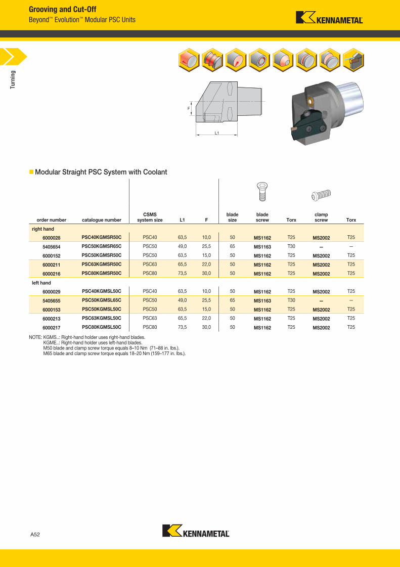
A52
L V i A052 A053 KMT I i 2016 B d E l i P d B h 052 053 EN J l 920154 46PM
Grooving and Cut-Off
Beyond™ Evolution™ Modular PSC Units
Modular Straight PSC System with Coolant
order number catalogue numberCSMS
system size L1 Fblade size
blade screw Torx
clampscrew Torx
right hand
6000028 PSC40KGMSR50C PSC40 63,5 10,0 50 MS1162 T25 MS2002 T25
5405654 PSC50KGMSR65C PSC50 49,0 25,5 65 MS1163 T30 — —
6000152 PSC50KGMSR50C PSC50 63,5 15,0 50 MS1162 T25 MS2002 T25
6000211 PSC63KGMSR50C PSC63 65,5 22,0 50 MS1162 T25 MS2002 T25
6000216 PSC80KGMSR50C PSC80 73,5 30,0 50 MS1162 T25 MS2002 T25
left hand
6000029 PSC40KGMSL50C PSC40 63,5 10,0 50 MS1162 T25 MS2002 T25
5405655 PSC50KGMSL65C PSC50 49,0 25,5 65 MS1163 T30 — —
6000153 PSC50KGMSL50C PSC50 63,5 15,0 50 MS1162 T25 MS2002 T25
6000213 PSC63KGMSL50C PSC63 65,5 22,0 50 MS1162 T25 MS2002 T25
6000217 PSC80KGMSL50C PSC80 73,5 30,0 50 MS1162 T25 MS2002 T25
NOTE: KGMS..: Right-hand holder uses right-hand blades. KGME..: Right-hand holder uses left-hand blades. M50 blade and clamp screw torque equals 8–10 Nm (71–88 in. lbs.). M65 blade and clamp screw torque equals 18–20 Nm (159–177 in. lbs.).
Turn
ing
A052_A053_KMT_Innovations_2016_Beyond_Evolution_Product_Brochure_052_053_EN_me.indd 52 7/28/15 1:17 PM

Looking for a product that’s not shown in this catalogue?
Check the Kennametal website!
Online product catalogue available 24/7
Turning
Visit http://www.kennametal.com/Turning/ to browse our electronic catalogue any time you’re looking for Kennametal’s best tooling solutions.
It’s fast, free, and always available. The online e-catalogue is updated weekly with products and solutions for milling, turning, holemaking,
and tooling systems applications.
A052_A053_KMT_Innovations_2016_Beyond_Evolution_Product_Brochure_052_053_EN_me.indd 53 7/28/15 1:17 PM
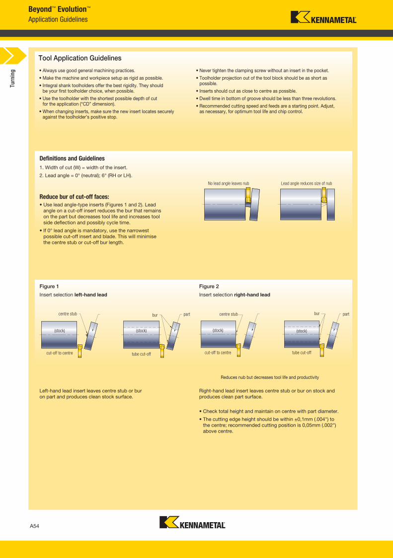
A54
L V i A054 A055 KMT I i 2016 B d E l i P d B h 054 055 EN J l 142015825AM
Beyond™ Evolution™
Application Guidelines
Tool Application Guidelines
• Always use good general machining practices.
• Make the machine and workpiece setup as rigid as possible.
• Integral shank toolholders offer the best rigidity. They shouldbe your first toolholder choice, when possible.
• Use the toolholder with the shortest possible depth of cutfor the application (“CD” dimension).
• When changing inserts, make sure the new insert locates securely against the toolholder’s positive stop.
• Never tighten the clamping screw without an insert in the pocket.
• Toolholder projection out of the tool block should be as short as possible.
• Inserts should cut as close to centre as possible.
• Dwell time in bottom of groove should be less than three revolutions.
• Recommended cutting speed and feeds are a starting point. Adjust,as necessary, for optimum tool life and chip control.
Definitions and Guidelines
1. Width of cut (W) = width of the insert.
2. Lead angle = 0° (neutral); 6° (RH or LH).
Reduce bur of cut-off faces:
• Use lead angle-type inserts (Figures 1 and 2). Lead
angle on a cut-off insert reduces the bur that remains
on the part but decreases tool life and increases tool
side deflection and possibly cycle time.
• If 0° lead angle is mandatory, use the narrowest
possible cut-off insert and blade. This will minimise
the centre stub or cut-off bur length.
No lead angle leaves nub Lead angle reduces size of nub
Figure 1
Insert selection left-hand lead
Left-hand lead insert leaves centre stub or bur
on part and produces clean stock surface.
centre stub bur
(stock)
cut-off to centre tube cut-off
(stock)
Figure 2
Insert selection right-hand lead
Right-hand lead insert leaves centre stub or bur on stock and
produces clean part surface.
• Check total height and maintain on centre with part diameter.
• The cutting edge height should be within ±0,1mm (.004") to
the centre; recommended cutting position is 0,05mm (.002")
above centre.
Reduces nub but decreases tool life and productivity
centre stub partbur
(stock)
cut-off to centre tube cut-off
(stock)
part
Turn
ing
A054_A055_KMT_Innovations_2016_Beyond_Evolution_Product_Brochure_054_055_EN_me.indd 54 7/28/15 1:17 PM
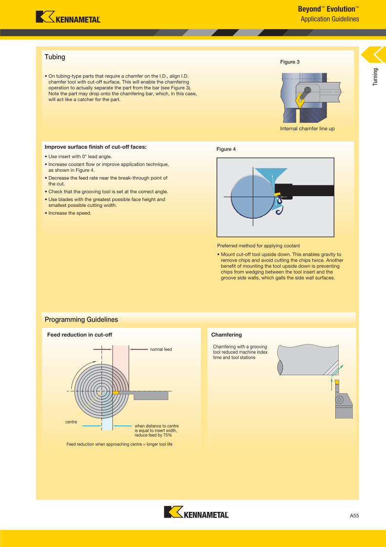
A55
L V i A054 A055 KMT I i 2016 B d E l i P d B h 054 055 EN J l142015825AM
Figure 3
• On tubing-type parts that require a chamfer on the I.D., align I.D.
chamfer tool with cut-off surface. This will enable the chamfering
operation to actually separate the part from the bar (see Figure 3).
Note the part may drop onto the chamfering bar, which, in this case,
will act like a catcher for the part.
Figure 4
Internal chamfer line up
Beyond™ Evolution™
Application Guidelines
Improve surface finish of cut-off faces:
• Use insert with 0° lead angle.
• Increase coolant flow or improve application technique,
as shown in Figure 4.
• Decrease the feed rate near the break-through point of
the cut.
• Check that the grooving tool is set at the correct angle.
• Use blades with the greatest possible face height and
smallest possible cutting width.
• Increase the speed.
Tubing
Preferred method for applying coolant
• Mount cut-off tool upside down. This enables gravity to
remove chips and avoid cutting the chips twice. Another
benefit of mounting the tool upside down is preventing
chips from wedging between the tool insert and the
groove side walls, which galls the side wall surfaces.
Programming Guidelines
Chamfering
Chamfering with a grooving tool reduced machine index time and tool stations
Feed reduction in cut-off
normal feed
centre
Feed reduction when approaching centre = longer tool life
when distance to centre is equal to insert width, reduce feed by 75%
Turn
ing
A054_A055_KMT_Innovations_2016_Beyond_Evolution_Product_Brochure_054_055_EN_me.indd 55 7/28/15 1:17 PM
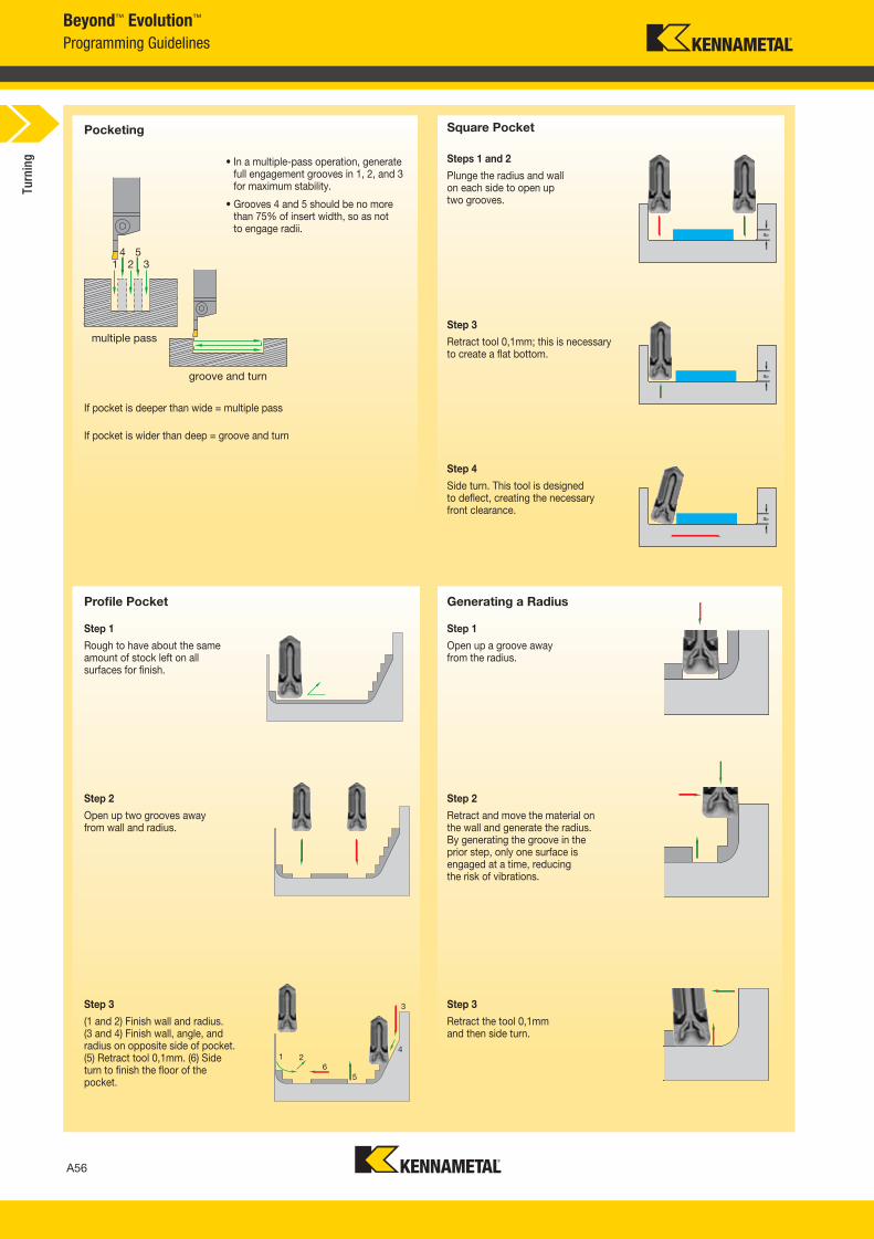
A56
L V i A056 A057 KMT I i 2016 B d E l i P d B h 056 057 EN J l 202015742AM
Beyond™ Evolution™
Programming Guidelines
Generating a Radius
Steps 1 and 2
Step 3
Step 4
Step 1 Step 1
Step 2 Step 2
Step 3 Step 3
groove and turn
If pocket is deeper than wide = multiple pass
• In a multiple-pass operation, generate full engagement grooves in 1, 2, and 3 for maximum stability.
• Grooves 4 and 5 should be no more than 75% of insert width, so as notto engage radii.
Plunge the radius and wall on each side to open up two grooves.
Retract tool 0,1mm; this is necessary to create a flat bottom.
Side turn. This tool is designed to deflect, creating the necessary front clearance.
Rough to have about the same amount of stock left on all surfaces for finish.
Open up a groove away from the radius.
Open up two grooves away from wall and radius.
Retract and move the material on the wall and generate the radius. By generating the groove in the prior step, only one surface is engaged at a time, reducing the risk of vibrations.
(1 and 2) Finish wall and radius. (3 and 4) Finish wall, angle, and radius on opposite side of pocket. (5) Retract tool 0,1mm. (6) Side turn to finish the floor of the pocket.
Retract the tool 0,1mm and then side turn.
If pocket is wider than deep = groove and turn
multiple pass
Pocketing Square Pocket
Profile Pocket
Turn
ing
A056_A057_KMT_Innovations_2016_Beyond_Evolution_Product_Brochure_056_057_EN_me.indd 56 7/28/15 1:17 PM
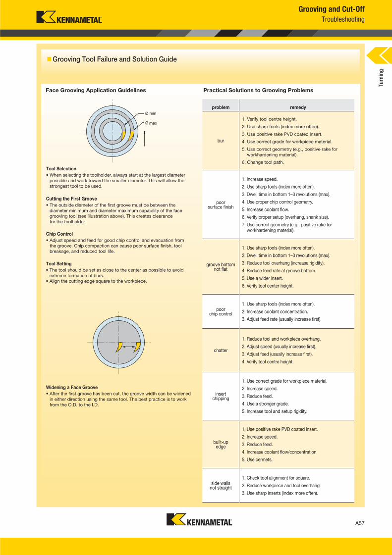
A57
L V i A056 A057 KMT I i 2016 B d E l i P d B h 056 057 EN J l202015742AM
Grooving and Cut-Off
Troubleshooting
Grooving Tool Failure and Solution Guide
Face Grooving Application Guidelines Practical Solutions to Grooving Problems
problem remedy
bur
1. Verify tool centre height.
2. Use sharp tools (index more often).
3. Use positive rake PVD coated insert.
4. Use correct grade for workpiece material.
5. Use correct geometry (e.g., positive rake for
workhardening material).
6. Change tool path.
poorsurface finish
1. Increase speed.
2. Use sharp tools (index more often).
3. Dwell time in bottom 1–3 revolutions (max).
4. Use proper chip control geometry.
5. Increase coolant flow.
6. Verify proper setup (overhang, shank size).
7. Use correct geometry (e.g., positive rake for workhardening material).
groove bottomnot flat
1. Use sharp tools (index more often).
2. Dwell time in bottom 1–3 revolutions (max).
3. Reduce tool overhang (increase rigidity).
4. Reduce feed rate at groove bottom.
5. Use a wider insert.
6. Verify tool center height.
poorchip control
1. Use sharp tools (index more often).
2. Increase coolant concentration.
3. Adjust feed rate (usually increase first).
chatter
1. Reduce tool and workpiece overhang.
2. Adjust speed (usually increase first).
3. Adjust feed (usually increase first).
4. Verify tool centre height.
insertchipping
1. Use correct grade for workpiece material.
2. Increase speed.
3. Reduce feed.
4. Use a stronger grade.
5. Increase tool and setup rigidity.
built-up edge
1. Use positive rake PVD coated insert.
2. Increase speed.
3. Reduce feed.
4. Increase coolant flow/concentration.
5. Use cermets.
side wallsnot straight
1. Check tool alignment for square.
2. Reduce workpiece and tool overhang.
3. Use sharp inserts (index more often).
• When selecting the toolholder, always start at the largest diameter
possible and work toward the smaller diameter. This will allow the
strongest tool to be used.
Tool Selection
Cutting the First Groove
• The outside diameter of the first groove must be between the
diameter minimum and diameter maximum capability of the face
grooving tool (see illustration above). This creates clearance
for the toolholder.
Chip Control
• Adjust speed and feed for good chip control and evacuation from
the groove. Chip compaction can cause poor surface finish, tool
breakage, and reduced tool life.
Tool Setting
• The tool should be set as close to the center as possible to avoid
extreme formation of burs.
• Align the cutting edge square to the workpiece.
Widening a Face Groove
• After the first groove has been cut, the groove width can be widened
in either direction using the same tool. The best practice is to work
from the O.D. to the I.D.
Turn
ing
A056_A057_KMT_Innovations_2016_Beyond_Evolution_Product_Brochure_056_057_EN_me.indd 57 7/28/15 1:17 PM

©2015 Kennametal Inc. l Latrobe, PA 15650 USA
All rights reserved. l A-15-04498EN_me
INNOVATIONS CATALOGUE
WORLD AND CORPORATE HEADQUARTERS
Kennametal Inc.
1600 Technology Way
Latrobe, PA 15650 USA
Phone: 800 446 7738 (United States and Canada)
E-mail: [email protected]
EUROPEAN HEADQUARTERS
Kennametal Europe GmbH
Rheingoldstrasse 50
CH 8212 Neuhausen am Rheinfall
Switzerland
Phone: +41 52 6750 100
E-mail: [email protected]
ASIA-PACIFIC HEADQUARTERS
Kennametal Singapore Pte. Ltd.
3A International Business Park
Unit #01-02/03/05, ICON@IBP
Singapore 609935
Phone: +65 6265 9222
E-mail: [email protected]
INDIA HEADQUARTERS
Kennametal India Limited
CIN: L27109KA1964PLC001546
8/9th Mile, Tumkur Road
Bangalore - 560 073
Phone: +91 080 22198444 or +91 080 43281444
E-mail: [email protected]