Embed Size (px)
Citation preview

MASTER CATALOGINNOVATIONS
2013TOOLING SYSTEMS
MASTER CATALOGINNOVATIONS
WORLD AND CORPORATE HEADQUARTERSKennametal Inc.1600 Technology WayLatrobe, PA 15650 USAPhone: 800.446.7738 (United States and Canada)E-mail: [email protected]
EUROPEAN HEADQUARTERSKennametal Europe GmbHRheingoldstrasse 50CH 8212 Neuhausen am RheinfallSwitzerlandPhone: 41.52.6750.100E-mail: [email protected]
ASIA-PACIFIC HEADQUARTERSKennametal (Singapore) Pte. Ltd.3A International Business ParkUnit #01-02/03/05, ICON@IBPSingapore 609935Phone: 65.6265.9222E-mail: [email protected]
INDIA HEADQUARTERSKennametal India Limited8/9th Mile, Tumkur RoadBangalore - 560 073Phone: 91.80.2839 4321E-mail: [email protected]
MASTER
CATALOGINNOVATIONS
2013www.kennametal.com
www.kennametal.com©2012 Kennametal Inc., Latrobe, PA 15650 USAAll rights reserved. l A-12-02809

KEN_TOOLINGSYSTEMS11_I000_I001.qxp:WIDIA 11:29 AM Page I2

I1www.kennametal.com
Straight Shanks
Shrink Fit Toolholders . . . . . . . . . . . . . . . . . . . . . . . . . . . . . . . . . . . . . . . . . . . . . . . . . . .I4–I5
TG Single-Angle Collet Chucks . . . . . . . . . . . . . . . . . . . . . . . . . . . . . . . . . . . . . . . . . . .I6–I7
Standard . . . . . . . . . . . . . . . . . . . . . . . . . . . . . . . . . . . . . . . . . . . . . . . . . . . . . . . . . . .I6
Tension and Compression . . . . . . . . . . . . . . . . . . . . . . . . . . . . . . . . . . . . . . . . . . . . . .I7
ER Single-Angle Collet Chucks . . . . . . . . . . . . . . . . . . . . . . . . . . . . . . . . . . . . . . . . . .I8–I11
Standard . . . . . . . . . . . . . . . . . . . . . . . . . . . . . . . . . . . . . . . . . . . . . . . . . . . . . . . .I8–I11
DA Double-Angle Collet Chucks . . . . . . . . . . . . . . . . . . . . . . . . . . . . . . . . . . . . . . . . .I12–I22
01 Series Standard . . . . . . . . . . . . . . . . . . . . . . . . . . . . . . . . . . . . . . . . . . . . . . .I12–I13
04 Series Standard . . . . . . . . . . . . . . . . . . . . . . . . . . . . . . . . . . . . . . . . . . . . . . .I14–I15
08 Series Standard . . . . . . . . . . . . . . . . . . . . . . . . . . . . . . . . . . . . . . . . . . . . . . .I16–I17
Tap Chucks . . . . . . . . . . . . . . . . . . . . . . . . . . . . . . . . . . . . . . . . . . . . . . . . . . . .I18–I20
Floating Holders . . . . . . . . . . . . . . . . . . . . . . . . . . . . . . . . . . . . . . . . . . . . . . . . .I21–I22
Screw-On Adapters for Modular Milling Cutters . . . . . . . . . . . . . . . . . . . . . . . . . . . .I23–I26
Slotting Cutter Adapters . . . . . . . . . . . . . . . . . . . . . . . . . . . . . . . . . . . . . . . . . . . . . . . . . .I27
KEN_TOOLINGSYSTEMS11_I000_I001.qxp:WIDIA 1:23 PM Page I1

I2 www.kennametal.com
Shank Tooling System • Straight Shank Tools
Primary ApplicationStraight Shank Toolholders are ideal for extending tool length to reach difficult-to-machine areas. These toolholders are intended for use in combination with other toolholder and adapter systems.
Features and Benefits
• All non-critical surfaces are black oxide.
• Design enables coolant as a standard feature on most designs.
• Clean components prior to assembly.
• To avoid destroying the toolholder, never over tighten toolholders or neglect surface damage.
KEN_TOOLINGSYSTEMS11_I002_I003.qxp:WIDIA 11:29 AM Page I2

How Do Catalog Numbers Work?Each character in our catalog number signifies a specific trait of thatproduct. Use the following key columns and corresponding imagesto easily identify which attributes apply.
I3www.kennametal.com
Straight Shank ToolsCatalog Numbering System
SSShankStyle
120Shank Taper
Size
TGToolholder
Style
50Toolholder
Size
100Tool
Length
MIdentification
Value
120 = 12mm
125 = 12,5mm
160 = 16mm
190 = 19mm
200 = 20mm
250 = 25mm
038 = 3/8"
050 = 1/2"
062 = 5/8"
075 = 3/4"
100 = 1"
125 = 1-1/4"
150 = 1-1/2"
175 = 1-3/4"
200 = 2"
(Flange face tofront of tool)
metricxxx = xxx
inch xxx = x.xx
TG =Collet series xx (50), xxx (100)
EM =I.D. size: metric — xx = xx, (20);
inch — xxx = x.xx, (075)
SM =O.D. size: metric — xx = xx, (20);
inch — xxx = x.xx, (075)
DA = Double-angle collet chuck
DP = Double pin, floating holder
ER = DIN 6499 single-angle collet chuck
FC = Fully floating holder
SA = Slotting cutter adapter
STL = DAL — tapping adapter, solid
TCJ = DAJ — tapping adapter,tension and compression
TCK = DAK — tapping adapter,tension and compression
TCL = DAL — tapping adapter, tension and compression
TCTG = TG — tapping adapter, tension and compression
TG = Tremendous Grip single-angle collet chuck
TOJ = DAJ — tapping adapter, tension only
TOK = DAK — tapping adapter,tension only
TOL = DAL — tapping adapter,tension only
TT = Shrink Fit thermo toolholder
M = Tool built to metric values
(blank) = Tool built to inch values
SS120TG50100M
KEN_TOOLINGSYSTEMS11_I002_I003.qxp:WIDIA 11:29 AM Page I3

I4 www.kennametal.com
Str
aig
ht
Sh
an
k T
oo
ls
order number catalog number D D1 D2 D21 L LS L9 Vstop
screwwrench sizestop screw kg
2264458 SS160TT03110M 16 3 9 15 110 50 15 10 TTSS05014M 2,5mm 0,11
2456194 SS160TT04110M 16 4 9 15 110 50 15 10 TTSS05014M 2,5mm 0,12
1801299 SS200TT04150M 20 4 9 15 150 60 15 10 TTSS05014M 2,5mm 0,22
1801300 SS200TT05150M 20 5 9 15 150 60 15 10 TTSS06014M 3mm 0,22
1801301 SS200TT06150M 20 6 15 — 150 118 26 10 TTSS05014M 2,5mm 0,30
1801302 SS200TT08150M 20 8 15 — 150 118 26 10 TTSS06014M 3mm 0,30
1801413 SS200TT10150M 20 10 20 27 150 50 31 10 TTSS08014M 4mm 0,46
1801414 SS200TT12150M 20 12 20 27 150 50 36 10 TTSS10014M 5mm 0,44
Cutting Tool Shank Requirements
metric (ISO standard)
cutting tool
toleranceshank diameter
3 h4 0,000/-0,003
4 h4 0,000/-0,004
5 h5 0,000/-0,005
6 h6 0,000/ -0,008
8 & 10 h6 0,000/ -0,009
12 h6 0,000/ -0,011
Straight Shank ToolsShrink Fit Toolholders General Purpose (GP)
• Suitable for carbide and HSS cutting tools (requirements below).
• Slim design for extending adapters, collet chucks,and toolholders.
• 10mm (3/8") axial adjustment.
� TT GP MM-SS MM
(continued)
KEN_TOOLINGSYSTEMS11_I004_I005.qxp:WIDIA 11:30 AM Page I4

Str
aig
ht
Sh
an
k T
oo
ls
I5www.kennametal.com
order number catalog number D D1 D2 D21 L LS L9 Vstop
screwwrench sizestop screw lbs
1794109 SS050TT012600 1/2 1/8 .35 .50 6.00 5.07 .61 .39 TTSS05014M 2,5mm .26
1794110 SS050TT018600 1/2 3/16 .35 .50 6.00 5.07 .61 .39 TTSS06014M 3mm .25
1794111 SS075TT025600 3/4 1/4 .59 .75 6.00 4.98 1.02 .39 TTSS05014M 2,5mm .62
1794112 SS075TT031600 3/4 5/16 .59 .75 6.00 4.98 1.02 .39 TTSS06014M 3mm .61
1794233 SS075TT038600 3/4 3/8 .79 1.06 6.00 1.50 1.22 .39 TTSS08014M 4mm 1.07
1794234 SS075TT044600 3/4 7/16 .79 1.06 6.00 1.50 1.42 .39 TTSS10014M 4mm 1.05
1794235 SS075TT050600 3/4 1/2 .79 1.06 6.00 1.50 1.42 .39 TTSS10014M 5mm 1.02
1794236 SS100TT056700 1 9/16 .95 1.26 7.00 1.75 1.42 .39 TTSS10014M 4mm 1.72
1794237 SS100TT062700 1 5/8 .95 1.26 7.00 1.75 1.54 .39 TTSS12014M 6mm 1.68
Cutting Tool Shank Requirements
inch (industry standard)
cutting tool
toleranceshank diameters
1/8 & 3/16 .0000/-.0003
1/4, 5/16, & 3/8 .0000/-.0004
7/16, 1/2, 9/16, & 5/8 .0000/-.0004
� TT GP IN-SS IN
Straight shank toolholders are a great complement to the Shrink Fit program. Use caution to not overheat the Slim Line design. Overheating can causewarping or permanent damage. The life cycle of the toolholders will be drastically reduced if the activating heat is not controlled. The Slim Line designpermits only a limited number of heat shrinks. Testing has shown more than 300 heat shrinks can be performed with the straight shank extensionswhen the activation heat is controlled to less than 426 °C (800 °F).
(TT GP continued)
Straight Shank ToolsShrink Fit Toolholders General Purpose (GP)
NOTE: Do not overheat. Overheating will destroy the accuracy and functionality of the toolholder.Shrink Fit technical section, see page M78.Supplied with stop screw.Adjusting stop screw gage, see page M81.For Shrink Fit machine and accessories, see pages L12–L13.
KEN_TOOLINGSYSTEMS11_I004_I005.qxp:WIDIA 11:30 AM Page I5
I6 www.kennametal.com
Str
aig
ht
Sh
an
k T
oo
ls
Collet Capacity
mm inch
TG collet series min max min max
TG50 1,1 13,5 1/32 17/32
TG75 2,6 20,0 3/64 3/4
TG100 2,6 25,5 5/64 1
• Tremendous Grip (3:1 advantage).
� TG Hex-SS IN
order number catalog numbercolletseries D D11 L L2 L9 V locknut wrench ft. lbs.
stop screw
wrench sizestop screw lbs
1025637 SS100TG050698G TG50 1 1.50 6.98 1.49 1.77 4.53 LNA050M HSW34M 50 SS062041G 4mm & 5/32 1.15
collet series
collet series
� TG Round-SS IN
order number catalog numbercolletseries D D11 L L9 LS V locknut
locknutwrench ft. lbs.
stop screw
wrench sizestop screw lbs
1082537 SS100TG050719 TG50 1 1.19 7.19 1.77 5.49 4.73 NPA050 OEW106 75 SS062041G 4mm & 5/32 1.03
1025794 SS125TG075850 TG75 1 1/4 2.09 8.50 2.06 6.00 3.56 NPA075 OEW188 100 SS081041G 4mm & 5/32 2.28
1025797 SS150TG075775 TG75 1 1/2 2.09 7.75 2.06 6.00 5.00 NPA075 OEW188 100 SS081041G 4mm & 5/32 2.97
2636807 SS125TG100925 TG100 1 1/4 2.44 9.25 2.88 6.00 3.63 NPA100 OEW225 150 SS081041G 4mm & 5/32 3.27
1025638 SS150TG100925 TG100 1 1/2 2.44 9.25 2.63 6.00 5.93 NPA100 OEW225 150 SS112041G 4mm & 5/32 3.52
1025796 SS175TG100819 TG100 1 3/4 2.44 8.19 2.63 6.02 4.87 NPA100 OEW225 150 SS112041G 4mm & 5/32 4.15
1025795 SS200TG100819 TG100 2 2.44 8.19 2.76 6.00 4.74 NPA100 OEW225 150 SS112041G 4mm & 5/32 5.38
Straight Shank ToolsTG Single-Angle Collet Chucks
NOTE: Collet must be loaded into locknut first. Before loading into the chuck body, insert the cutting tool, then tighten to the recommended tightening torque.Collet chuck technical section, see page M98.Supplied with locknut and stop screw.Locknut wrench must be ordered separately.Interchangeable locknuts, coolant-style locknuts, and coolant disks are available and must be ordered separately; see pages L16–L17.Stop screw coolant caps are available and must be ordered separately; see pages L34–L35.TG standard straight-bore collets, see page J10.TG tap collets, see page J10.
KEN_TOOLINGSYSTEMS11_I006_I007.qxp:WIDIA 11:30 AM Page I6

Str
aig
ht
Sh
an
k T
oo
ls
I7www.kennametal.com
order number catalog numbercolletseries D D11 D2 L LS tension compression
hex assembly OEW ft. lbs. lbs
1288221 SS075TCTG050 TG50 3/4 1.22 1.48 5.48 2.00 .25 .30 NPA050 OEW106 75 .68
order number catalog numbercolletseries D D11 D2 L LS tension compression locknut wrench ft. lbs. lbs
1288256 SS100TCTG075 TG75 1 1.97 1.88 6.79 2.20 .40 .43 LNA075M HSW45M 100 1.50
1017625 SS150TCTG100756 TG100 1 1/2 2.36 2.50 7.56 2.68 .50 .13 LNA100M HSW58M 150 2.12
• Tremendous Grip (3:1 advantage).
• Anti-friction drive.
• Compact design.
• Adjustment hard start.
collet series
� TG Hex Tap T&C-SS IN
� TG Round Tap T&C-SS IN
Collet Capacity
mm inch
TG collet series min max min max
TG50 1,1 13,5 1/32 17/32
TG75 2,6 20,0 3/64 3/4
TG100 2,6 25,5 5/64 1
collet series
Straight Shank ToolsTG Single-Angle Collet Chucks Tension and Compression
NOTE: Collet must be loaded into locknut first. Before loading into the chuck body, insert the cutting tool, then tighten to the recommended tightening torque.Collet chuck technical section, see page M98.Supplied with locknut.Locknut wrench must be ordered separately.Interchangeable locknuts, coolant-style locknuts, and coolant disks are available and must be ordered separately; see pages L16–L17.TG standard straight-bore collets, see page J10.TG tap collets, see page J10.
KEN_TOOLINGSYSTEMS11_I006_I007.qxp:WIDIA 11:30 AM Page I7

I8 www.kennametal.com
Str
aig
ht
Sh
an
k T
oo
ls
Collet Capacity
mm inch
ER collet series min max min max
ER11 0,5 7,0 .02 .28
ER16 0,5 10,0 .02 .41
ER20 0,5 13,0 .02 .50
ER25 1,0 16,0 .04 .63
ER32 1,0 20,0 .04 .79
order number catalog numbercolletseries D D11 L LS L9 V kg
1288261 SS120ER11107M ER11 12 16 107 80 24 56 0,08
1288285 SS160ER11132M ER11 16 16 132 100 24 56 0,16
1125015 SS200ER16182M ER16 20 22 182 140 32 68 0,32
1288321 SS250ER20190M ER20 25 28 190 150 36 64 0,55
catalog number locknutlocknut wrench
counterbore collettorque (Nm)
straight collettorque (Nm)
stop screw
wrench sizestop screw
SS120ER11107M LER11M ER11WEM 12 16 CSS0615M 3mm
SS200ER16182M LER16M ER16WEM 24 24 CSS1020M 5mm
SS250ER20190M LER20M ER20WEM 28 28 CSS1225M 6mm
Straight Shank ToolsER Single-Angle Collet Chucks
• Grip (2:1 advantage).
� ER Slim-SS MM
� Spare Parts
(continued)
collet series
KEN_TOOLINGSYSTEMS11_I008_I009.qxp:WIDIA 11:30 AM Page I8

Str
aig
ht
Sh
an
k T
oo
ls
I9www.kennametal.com
order number catalog numbercolletseries D D11 L LS L9 V kg
1288303 SS200ER25146M ER25 20 42 146 100 42 58 0,38
1288304 SS200ER32154M ER32 20 50 154 100 49 51 0,51
catalog number locknutlocknut wrench Nm
stop screw
wrench sizestop screw
SS200ER25146M LNSER25M ER25WM 104 CSS1225M 6mm
SS200ER32154M LNSER32M ER32WM 136 CSS1225M 6mm
� ER Round-SS MM
� Spare Parts
(ER SS MM continued)
Straight Shank ToolsER Single-Angle Collet Chucks
collet series
NOTE: Collet must be loaded into locknut first. Before loading into the chuck body, insert the cutting tool, then tighten to the recommended tightening torque.Collet chuck technical section, see page M98.Supplied with locknut and stop screw.Locknut wrench must be ordered separately.ER standard straight-bore collets, see page J50.ER tap collets, see pages J58–J59.ER TCT tension-only tap collets, see page J60.
KEN_TOOLINGSYSTEMS11_I008_I009.qxp:WIDIA 11:30 AM Page I9

I10 www.kennametal.com
Str
aig
ht
Sh
an
k T
oo
ls
Collet Capacity
mm inch
ER collet series min max min max
ER8 0,5 0,5 .02 .20
ER11 0,5 7,0 .02 .28
ER16 0,5 10,0 .02 .41
ER20 0,5 13,0 .02 .50
ER25 1,0 16,0 .04 .63
order number catalog numbercolletseries D D11 L LS L9 V lbs
1021460 SS038ER08500 ER8 3/8 .47 5.00 4.15 .71 1.42 .10
1021462 SS050ER11700 ER11 1/2 .63 7.00 5.96 .95 3.23 .26
1021494 SS075ER16700 ER16 3/4 .87 7.00 5.47 1.30 2.24 .56
catalog number locknut wrench Nmstop
screwwrench sizestop screw
SS038ER08500 LER08M ER08WEM 4.8 SS025031PKG —
SS050ER11700 LER11M ER11WEM 12.0 SS031031G 2mm & 5/64
SS075ER16700 LER16M ER16WEM 24.0 SS044038G 4mm & 5/32
Straight Shank ToolsER Single-Angle Collet Chucks
• Grip (2:1 advantage).
� ER Slim-SS IN
� Spare Parts
(continued)
collet series
KEN_TOOLINGSYSTEMS11_I010_I011.qxp:WIDIA 11:30 AM Page I10

Str
aig
ht
Sh
an
k T
oo
ls
I11www.kennametal.com
order number catalog numbercolletseries D D11 L LS L9 V lbs
1021496 SS100ER20700 ER20 1.00 1.34 7.00 5.70 1.30 2.20 1.07
catalog number locknut wrenchcounterbore collet
torque (ft. lbs.)straight collettorque (ft. lbs.)
stop screw
wrench sizestop screw
SS100ER20700 LNHSER20M OEW30M 24 59 SS056041G 4mm & 5/32
order number catalog numbercolletseries D D11 L LS L9 V lbs
1021498 SS100ER25750 ER25 1.00 1.65 7.50 5.69 1.58 1.97 1.13
catalog number locknut wrench ft. lbs.stop
screwwrench sizestop screw
SS100ER25750 LNSER25M ER25WM 77 SS075041G 4mm & 5/32
� ER Hex-SS IN
� Spare Parts
� ER Round-SS IN
� Spare Parts
(ER SS IN continued)
VL9
D11
LS
L
collet series
collet series
Straight Shank ToolsER Single-Angle Collet Chucks
NOTE: Collet must be loaded into locknut first. Before loading into the chuck body, insert the cutting tool, then tighten to the recommended tightening torque.Collet chuck technical section, see page M98.Supplied with locknut and stop screw.Locknut wrench must be ordered separately.ER standard straight-bore collets, see page J50.ER tap collets, see pages J58–J59.ER TCT tension-only tap collets, see page J60.
KEN_TOOLINGSYSTEMS11_I010_I011.qxp:WIDIA 11:30 AM Page I11

I12 www.kennametal.com
Str
aig
ht
Sh
an
k T
oo
ls
order number catalog numbercolletseries D D2 D11 L L2 LS L9 V lbs
1015309 SS050DA301544 DA300 1/2 .50 .87 5.44 .62 3.98 1.25 2.9370 .23
1015312 SS062DA301319 DA300 5/8 .50 .87 3.19 .62 1.73 1.21 1.4800 .21
1015313 SS062DA301544 DA300 5/8 .50 .87 5.44 .62 3.98 1.25 2.9410 .36
1015736 SS062DA201325 DA200 5/8 .81 1.44 3.25 .91 1.26 1.30 1.4600 .45
1015522 SS062DA201600 DA200 5/8 .81 1.44 6.00 .91 4.01 1.42 2.7559 .60
1015483 SS075DA301344 DA300 3/4 .50 .86 3.44 .61 — 1.22 1.7300 .30
1015695 SS075DA301544 DA300 3/4 .50 .86 5.44 — 3.96 1.26 3.5400 .51
1015669 SS075DA201600 DA200 3/4 .81 1.44 6.00 .91 4.01 1.11 3.0120 .71
1015601 SS075DA101650 DA100 3/4 1.06 1.73 6.50 — 3.96 1.57 4.1800 .98
1015666 SS100DA301544 DA300 1 .50 .86 5.44 .62 3.96 1.22 3.0300 .89
1015340 SS100DA201600 DA200 1 .81 1.44 6.00 .88 4.01 1.50 2.5980 1.10
1015520 SS100DA101650 DA100 1 1.06 1.73 6.50 1.26 3.96 1.69 4.0200 1.24
1015625 SS100DA181638 DA180 1 1.32 2.02 6.38 — 3.96 1.69 4.0160 1.33
1015375 SS125DA181838 DA180 1 1/4 1.32 2.02 8.38 2.42 5.96 1.73 3.9800 2.12
1015378 SS150DA201600 DA200 1 1/2 .81 1.44 6.00 — 4.01 1.50 2.6300 2.21
1015597 SS150DA181838 DA180 1 1/2 1.32 2.02 8.38 — 5.96 1.50 4.2100 3.03
1015764 SS200DA201800 DA200 2 .81 1.44 8.00 .91 6.01 1.50 2.6378 5.45
1015765 SS200DA101850 DA100 2 1.06 1.73 8.50 1.26 5.97 1.70 4.0160 5.46
1015631 SS200DA181838 DA180 2 1.32 2.02 8.38 .99 5.98 1.88 5.9060 5.41
Straight Shank ToolsDA 01 Series Double-Angle Collet Chucks
• Grip 1:1.
� DA 01-SS IN
(continued)
Collet Capacity
mm inch
DA collet series min max min max
DA300 0,2 6 1/64 1/4
DA200 0,2 10 1/64 25/64
DA100 1,8 14 1/64 9/16
DA180 2,2 20 1/64 3/4
collet series
KEN_TOOLINGSYSTEMS11_I012_I013.qxp:WIDIA 11:30 AM Page I12

Str
aig
ht
Sh
an
k T
oo
ls
I13www.kennametal.com
� Spare Parts
catalog numbernose piece
hex locknut
locknut wrench ft. lbs.
stop screw
wrench sizestop screw
SS050DA301544 NP301 LN301 OEW075 20 SS031031G 2mm & 5/64
SS062DA301319 NP301 LN301 OEW075 20 SS031031G 2mm & 5/64
SS062DA301544 NP301 LN301 OEW075 20 SS031031G 2mm & 5/64
SS062DA201325 NP201 LN201 OEW125 40 SS038031G 2mm & 5/64
SS062DA201600 NP201 LN201 OEW125 40 SS038031G 2mm & 5/64
SS075DA301344 NP301 LN301 OEW075 20 SS031031G 2mm & 5/64
SS075DA301544 NP301 LN301 OEW075 20 SS031031G 2mm & 5/64
SS075DA201600 NP201 LN201 OEW125 40 SS044038G 4mm & 5/32
SS075DA101650 NP101 LN101 OEW150 45 SS050038G 4mm & 5/32
SS100DA301544 NP301 LN301 OEW075 20 SS031031G 2mm & 5/64
SS100DA201600 NP201 LN201 OEW125 40 SS044038G 4mm & 5/32
SS100DA101650 NP101 LN101 OEW150 45 SS062041G 4mm & 5/32
SS100DA181638 NP181 LN181 OEW175 75 SS075041G 4mm & 5/32
SS125DA181838 NP181 LN181 OEW150 75 SS081041G 4mm & 5/32
SS150DA201600 NP201 LN201 OEW125 40 SS044038G 4mm & 5/32
SS150DA181838 NP181 LN181 OEW175 75 SS081041G 4mm & 5/32
SS200DA201800 NP201 LN201 OEW125 40 SS044038G 4mm & 5/32
SS200DA101850 NP101 LN101 OEW150 45 SS062041G 4mm & 5/32
SS200DA181838 NP181 LN181 OEW175 75 SS081041G 4mm & 5/32
(DA 01-SS IN continued)
Straight Shank ToolsDA 01 Series Double-Angle Collet Chucks
NOTE: Tighten locknut to the recommended tightening torque.Collet chuck technical section, see page M98.Supplied with locknut and stop screw.Locknut wrench must be ordered separately.Stop screw coolant caps are available and must be ordered separately; see pages L34–L35.DA standard straight-bore collets, see page J62.DA non-pullout collets, see pages J65–J68.
KEN_TOOLINGSYSTEMS11_I012_I013.qxp:WIDIA 11:30 AM Page I13

I14 www.kennametal.com
Str
aig
ht
Sh
an
k T
oo
ls
L
order number catalog numbercolletseries D D11 L LS L9 V kg
1015043 SS080DA000132M DA000 8,0 10,1 132 100 — — 0,05
1015037 SS125DA304109M DA300 12,5 14,2 109 72 33 63 0,07
1015038 SS125DA304173M DA300 12,5 14,2 173 136 34 126 0,11
1015034 SS190DA204117M DA200 19,1 21,5 117 74 37 65 0,19
1015013 SS190DA204181M DA200 19,1 21,5 181 138 42 124 0,29
1015035 SS200DA204117M DA200 20,0 21,5 117 74 38 65 0,21
1015036 SS200DA204181M DA200 20,0 21,5 181 138 37 128 0,32
1015011 SS250DA104122M DA100 25,0 27,0 122 73 46 61 0,29
1015012 SS250DA104186M DA100 25,0 27,0 186 137 46 124 0,45
catalog number locknutlocknut wrench Nm
stop screw
wrench sizestop screw
SS080DA000132M LN000M OEW9M 41 — —
SS125DA304109M LNA304M OEW13M 27 SS031031G 2mm & 5/64
SS125DA304173M LNA304M OEW13M 27 SS031031G 2mm & 5/64
SS190DA204117M LNA204M OEW19M 54 SS044038G 4mm & 5/32
SS190DA204181M LNA204M OEW19M 54 SS044038G 4mm & 5/32
SS200DA204117M LNA204M OEW19M 54 SS044038G 4mm & 5/32
SS200DA204181M LNA204M OEW19M 54 SS044038G 4mm & 5/32
SS250DA104122M LNA104M OEW24M 61 SS062041G 4mm & 5/32
SS250DA104186M LNA104M OEW24M 61 SS062041G 4mm & 5/32
Straight Shank ToolsDA 04 Series Double-Angle Collet Chucks
• Grip 1:1.
• Small outside diameter clearance is ideal for machining centers,close center-distance, and fixture problems.
� DA 04-SS MM
� Spare Parts
(continued)
Collet Capacity
mm inch
DA collet series min max min max
DA000 0,65 4 — —
DA300 0,2 6 1/64 1/4
DA200 0,2 10 1/64 25/64
DA100 1,8 14 1/64 9/16
DA180 2,2 20 1/64 3/4
collet series
KEN_TOOLINGSYSTEMS11_I014_I015.qxp:WIDIA 11:31 AM Page I14

Str
aig
ht
Sh
an
k T
oo
ls
I15www.kennametal.com
order number catalog numbercolletseries D D11 L LS L9 V lbs
1015308 SS050DA304438 DA300 1/2 .56 4.38 2.93 1.34 2.60 .17
1015311 SS050DA304681 DA300 1/2 .56 6.81 5.36 1.27 2.98 .24
1015334 SS075DA204469 DA200 3/4 .84 4.69 3.00 1.50 2.63 .42
1015337 SS075DA204712 DA200 3/4 .84 7.13 5.44 1.50 3.27 .62
1015338 SS100DA104488 DA100 1 1.06 4.88 2.95 1.69 2.56 .66
1015342 SS100DA104731 DA100 1 1.06 7.31 5.38 1.73 4.96 1.02
1015517 SS125DA184738 DA180 1 1/4 1.44 7.38 5.38 1.89 4.76 1.61
1015594 SS125DA184988 DA180 1 1/4 1.44 9.88 7.86 1.89 7.20 2.15
1015737 SS150DA404104 DA400 1 1/2 1.87 10.40 7.96 2.20 7.25 2.80
1015545 SS150DA404791 DA400 1 1/2 1.88 7.91 5.18 2.19 4.81 2.22
� DA 04-SS IN
� Spare Parts
catalog number locknut wrench ft. lbs.stop
screwwrench sizestop screw
SS050DA304438 LNA304M OEW050 20 SS031031G 2mm & 5/64
SS050DA304681 LNA304M OEW050 20 SS031031G 2mm & 5/64
SS075DA204469 LNA204M OEW075 40 SS044038G 4mm & 5/32
SS075DA204712 LNA204M OEW075 40 SS044038G 4mm & 5/32
SS100DA104488 LNA104M OEW094 45 SS062041G 4mm & 5/32
SS100DA104731 LNA104M OEW094 45 SS062041G 4mm & 5/32
SS125DA184738 LNA184M OEW119 60 SS081041G 4mm & 5/32
SS125DA184988 LNA184M OEW119 60 SS081041G 4mm & 5/32
SS150DA404104 LNA404M OEW168 64 SS112041G 4mm & 5/32
SS150DA404791 LNA404M OEW168 64 SS112041G 4mm & 5/32
(DA 04-SS continued)
Straight Shank ToolsDA 04 Series Double-Angle Collet Chucks
NOTE: Tighten locknut to the recommended tightening torque.Collet chuck technical section, see page M98.Supplied with locknut and stop screw.Locknut wrench must be ordered separately.Stop screw coolant caps are available and must be ordered separately; see pages L34–L35.DA standard straight-bore collets, see page J62.DA non-pullout collets, see pages J65–J68.
KEN_TOOLINGSYSTEMS11_I014_I015.qxp:WIDIA 11:31 AM Page I15

I16 www.kennametal.com
Str
aig
ht
Sh
an
k T
oo
ls
Collet Capacity
mm inch
DA collet series min max min max
DA300 0,2 6 1/64 1/4
DA200 0,2 10 1/64 25/64
DA100 1,8 14 1/64 9/16
DA180 2,2 20 1/64 3/4
order number catalog numbercolletseries D D11 L LS L9 V lbs
1015310 SS050DA308516 DA300 1/2 .79 5.16 3.98 1.34 2.91 .22
1015519 SS062DA308516 DA300 5/8 .77 5.16 3.98 1.38 2.80 .35
1015694 SS062DA208569 DA200 5/8 1.15 5.69 4.00 1.38 2.87 .44
1015336 SS075DA308516 DA300 3/4 .79 5.16 4.24 1.97 2.62 .50
1015335 SS075DA208531 DA200 3/4 1.15 5.31 3.96 1.45 2.68 .52
1015518 SS075DA108588 DA100 3/4 1.44 5.88 4.00 1.73 3.62 .67
1015696 SS100DA308516 DA300 1 .77 5.16 3.98 1.38 2.76 .88
1015734 SS100DA208431 DA200 1 1.15 4.31 2.96 1.50 2.24 .73
1015341 SS100DA208531 DA200 1 1.15 5.31 3.95 1.46 2.68 .91
1015698 SS100DA108556 DA100 1 1.44 5.56 3.99 1.75 3.21 .90
1015339 SS100DA188638 DA180 1 1.73 6.38 4.00 1.97 3.82 1.04
1015703 SS125DA208531 DA200 1-1/4 1.15 5.31 3.96 1.50 2.59 1.40
1015343 SS125DA108556 DA100 1-1/4 1.44 5.56 3.99 1.77 3.19 1.40
1015374 SS125DA108756 DA100 1-1/4 1.44 7.56 5.99 1.77 3.94 1.92
1015376 SS125DA188762 DA180 1-1/4 1.73 7.63 5.91 1.93 5.04 1.76
1015379 SS150DA208531 DA200 1-1/2 1.15 5.31 3.96 1.50 3.22 2.02
1015629 SS150DA208731 DA200 1-1/2 1.15 7.31 5.96 1.46 2.67 2.91
1015380 SS150DA108756 DA100 1-1/2 1.44 7.56 5.99 1.77 3.94 2.83
1015381 SS150DA188762 DA180 1-1/2 1.73 7.63 5.91 1.93 5.08 2.64
1015404 SS175DA188762 DA180 1-3/4 1.73 7.63 5.91 1.93 5.08 3.70
1015405 SS200DA188762 DA180 2 1.73 7.63 5.91 1.89 5.22 4.92
Straight Shank ToolsDA 08 Series Double-Angle Collet Chucks
• Grip 1:1.
• Heavy-duty design.
� DA 08-SS-IN
(continued)
collet series
KEN_TOOLINGSYSTEMS11_I016_I017.qxp:WIDIA 11:31 AM Page I16

Str
aig
ht
Sh
an
k T
oo
ls
I17www.kennametal.com
� Spare Parts
catalog number locknut wrench ft. lbs.stop
screwwrench sizestop screw
SS050DA308516 LNA308M OEW068 20 SS031031G 2mm & 5/64
SS062DA308516 LNA308M OEW068 20 SS031031G 2mm & 5/64
SS062DA208569 NPA208 OEW100 40 SS038031G 2mm & 5/64
SS075DA308516 LNA308M OEW068 20 SS031031G 2mm & 5/64
SS075DA208531 NPA208 OEW100 40 SS044038G 4mm & 5/32
SS075DA108588 LNA108M OEW125 55 SS050038G 4mm & 5/32
SS100DA308516 LNA308M OEW068 20 SS031031G 2mm & 5/64
SS100DA208431 NPA208 OEW100 40 SS044038G 4mm & 5/32
SS100DA208531 NPA208 OEW100 40 SS044038G 4mm & 5/32
SS100DA108556 LNA108M OEW125 55 SS062041G 4mm & 5/32
SS100DA188638 NPA188 OEW150 75 SS075041G 4mm & 5/32
SS125DA208531 NPA208 OEW100 40 SS044038G 4mm & 5/32
SS125DA108556 LNA108M OEW125 55 SS062041G 4mm & 5/32
SS125DA108756 LNA108M OEW125 55 SS062041G 4mm & 5/32
SS125DA188762 NPA188 OEW150 75 SS081041G 4mm & 5/32
SS150DA208531 NPA208 OEW100 40 SS044038G 4mm & 5/32
SS150DA208731 NPA208 OEW100 40 SS044038G 4mm & 5/32
SS150DA108756 LNA108M OEW125 55 SS062041G 4mm & 5/32
SS150DA188762 NPA188 OEW150 75 SS081041G 4mm & 5/32
SS175DA188762 NPA188 OEW150 75 SS081041G 4mm & 5/32
SS200DA188762 NPA188 OEW150 75 SS081041G 4mm & 5/32
(DA 08-SS IN continued)
Straight Shank ToolsDA 08 Series Double-Angle Collet Chucks
NOTE: For retention tighten locknut to the recommended tightening torque.Collet chuck technical section, see page M98.Supplied with locknut and stop screw.Locknut wrench must be ordered separately.Stop screw coolant caps are available and must be ordered separately; see pages L34–L35.DA standard straight-bore collets, see page J62.DA non-pullout collets, see pages J65–J68.
KEN_TOOLINGSYSTEMS11_I016_I017.qxp:WIDIA 11:31 AM Page I17

I18 www.kennametal.com
Str
aig
ht
Sh
an
k T
oo
ls
Collet Capacity
mm inch
DA L collet series min max min max min max
L M5 M24 #0 7/8 1/16P 1/2P
order number catalog numbercolletseries D D11 L LS locknut ft. lbs. wrench lbs
1017941 SS100STL169 L 1 1.50 3.19 1.50 LNAL04M 60 OEW125 1.59
Straight Shank ToolsDA L Tap Series Solid Tapping, Double-Angle Collet Chucks
• Grip 1:1.
• Industry standard Erickson™ double-angle collet system.
• Small outside diameter clearance is ideal for machiningcenters, close center-distance, and fixture issues.
• Solid drive/positive drive collets prevent tap slippage.
• Right- or left-hand tapping capability.
• Economical to use.
� DA L Tap Solid-SS IN
collet series
NOTE: Tighten locknut to the recommended tightening torque.Collet chuck technical section, see page M98.Supplied with locknut.Locknut wrench must be ordered separately.DA standard straight-bore collets, see page J62.
KEN_TOOLINGSYSTEMS11_I018_I019.qxp:WIDIA 11:31 AM Page I18

Str
aig
ht
Sh
an
k T
oo
ls
I19www.kennametal.com
Collet Capacity
mm inch
DA J, K, and L collet series min max min max min max
J M1 M12 #0 1/2 1/16P —
K M1 M16 #0 5/8 1/16P 1/8P
L M5 M24 #0 7/8 1/16P 1/2P
order number catalog numbercolletseries D D11 L LS L9 tension compression WF locknut ft. lbs. wrench lbs
1017581 SS075TCJ731 J 3/4 .85 7.31 5.44 1.50 .56 .19 .562 LNA204M 40 OEW075 .72
1017748 SS100TCK719 K 1 1.06 7.19 5.44 — .56 .19 .750 LNAK04M 45 OEW094 1.23
1017580 SS100TCL769 L 1 1.50 7.69 3.75 — .56 .19 1.125 LNAL04M 60 OEW125 2.06
Straight Shank ToolsDA J, K, and L Tap Series Double-Angle Collet Chucks Tension and Compression
• Grip 1:1.
• Industry standard Erickson™
double-angle collet system.
• Small outside diameter clearanceis ideal for use on machiningcenters, close center-distance,and fixture issues.
• Use for through hole tapping.
• Key drive.
• Right- or left-hand tappingcapability.
• Alternate springs available toadjust tension pressure to controlthread quality in a variety ofworkpiece conditions.
• Positive-drive collets prevent tap slippage.
• Economical to use.
� DA J, K, and L Tap T&C-SS • Inch
NOTE: Do not overtighten locknut; use torque recommendations above.Collet chuck technical section, see page M98.Supplied with locknut.Locknut wrench must be ordered separately.DA standard straight-bore collets, see page J62.
� Alternate Tension Adjustment Springs for Tension and Compression Chucks
tap chuck
standard spring
alternate spring
preload(lb/in²)
SS075TCJ731 CS0563041156PKG — 2.37
— —heavier
CS054001150PKG 3.50
SS100TCK719 CS0720067125PKG — 6.75
— —lightest
CS0563041156PKG 2.37
— —lightest
CS0600049125PKG 3.25
— —heavier
CS0600055150PKG 7.50
— —heaviest
CS0600072150PKG 18.00
SS100TCL769 CS0600072150PKG — 18.00
— —light
CS0600055150 PKG 7.50
NOTE: There are two springs in a package.
collet series
KEN_TOOLINGSYSTEMS11_I018_I019.qxp:WIDIA 11:31 AM Page I19

I20 www.kennametal.com
Str
aig
ht
Sh
an
k T
oo
ls
order number catalog numbercolletseries D D11 L LS L9 tension WF locknut ft. lbs. wrench lbs
1017627 SS075TOJ712 J 3/4 .85 7.13 5.44 1.50 .50 .562 LNA204M 40 OEW075 .72
1017629 SS100TOK700 K 1 1.06 7.00 5.44 1.47 .75 .750 LNAK04M 45 OEW094 1.14
1017631 SS100TOL750 L 1 1.50 7.50 3.75 1.59 .75 1.125 LNAL04M 60 OEW125 2.08
Straight Shank ToolsDA J, K, and L Tap Series Double-Angle Collet Chucks, Tension Only
• Grip 1:1.
• Industry standard Erickson™
double-angle collet system.
• Small outside diameter clearanceis ideal for use with machiningcenters, close center-distance,and fixture issues.
• Use for through hole tapping.
• Solid hard start ensures tap willstart at same point every time,regardless if it is sharp or dull.
• Key drive.
• Right- or left-hand tappingcapability.
• Alternate springs available toadjust tension pressure to controlthread quality in a variety ofworkpiece conditions.
• Positive-drive collets prevent tap slippage.
• Economical to use.
NOTE: Do not overtighten locknut; use torque recommendations above.Collet chuck technical section, see page M98.Supplied with locknut.Locknut wrench must be ordered separately.DA standard straight-bore collets, see page J62.
� Alternate Tension Adjustment Springs for Tension-Only Chucks
tap chuck
standard spring
alternate spring
preload(lb/in²)
SS075TOJ712 CS0563041156PKG — 2.37
— —heavier
CS0540041150 PKG 3.50
SS100TOK700 CS0600055150PKG — 7.50
— —lighter
CS0563041156 PKG 2.37
SS100TOL750 CS0600049125PKG — 3.25
— —heavier
CS0600055150 PKG 7.50
NOTE: There are two springs in a package.
Collet Capacity
mm inch
DA J, K, and Lcollet series min max min max min max
J M1 M12 #0 1/2 1/16P —
K M1 M16 #0 5/8 1/16P 1/8P
L M5 M24 #0 7/8 1/16P 1/2P
collet series
� DA J, K, and L Tap Tension Only-SS • Inch
KEN_TOOLINGSYSTEMS11_I020_I021.qxp:WIDIA 11:31 AM Page I20

Str
aig
ht
Sh
an
k T
oo
ls
I21www.kennametal.com
Collet Capacity
mm inch
DA collet series min max min max
DA300 0,2 6 1/64 1/4
DA200 0,2 10 1/64 25/64
DA100 1,8 14 1/64 9/16
DA180 2,2 20 1/64 3/4
order number catalog numbercolletseries D D11 L LS WF locknut wrench ft. lbs. lbs
1015905 SS050DP308403 DA300 1/2 .69 4.03 2.50 .500 NPA338 OEW062 20 .22
1015906 SS075DP308403 DA300 3/4 .69 4.03 2.50 .500 NPA338 OEW062 20 .50
1015980 SS075DP208448 DA200 3/4 .94 4.50 3.00 .625 NPA238 OEW088 40 .56
1015949 SS100DP308403 DA300 1 .69 4.03 2.50 .500 NPA338 OEW062 20 .89
1015981 SS100DP208448 DA200 1 .94 4.50 3.00 .625 NPA238 OEW088 40 .99
1015979 SS100DP108562 DA100 1 1.19 5.63 3.50 .875 NPA139 OEW088 55 1.24
1015944 SS125DP188696 DA180 1-1/4 1.50 6.97 4.50 1.125 LNA138 OEW138 75 2.41
Straight Shank ToolsDA 08 Double-Angle Collet Chucks, Double Pin Floating Holders
• Grip 1:1.
• Industry standard Erickson™ double-angle collet system.
• Ideal for machining centers.
• Tool holder provides 0,10mm (.004") movement in all directions to compensate for angular and parallel misalignments.
• Minimum outside diameter and overhang provide maximum tool clearance.
� DA 08 DP F-SS IN
NOTE: Do not overtighten locknut; use torque recommendations above.Using two wrenches is recommended to prevent premature wear on the floating mechanism. Wrenches must be ordered separately.Collet chuck technical section, see page M98.Supplied with locknut.DA standard straight-bore collets, see page J62.
collet series
KEN_TOOLINGSYSTEMS11_I020_I021.qxp:WIDIA 11:31 AM Page I21

I22 www.kennametal.com
order number catalog numbercolletseries D D11 D2 L LS locknut wrench wrench ft. lbs. lbs
1015975 SS075FC188688 DA180 3/4 1.73 2.38 6.88 4.00 NPA188 OEW150 HSW58M 75 .861015982 SS100FC188688 DA180 1 1.73 2.38 6.88 4.00 NPA188 OEW150 HSW58M 75 1.52
1015910 SS125FC188888 DA180 1 1/4 1.73 2.38 8.88 6.00 NPA188 OEW150 HSW58M 75 4.081015952 SS150FC188688 DA180 1 1/2 1.73 2.38 6.88 4.00 NPA188 OEW150 HSW58M 75 3.44
1015947 SS150FC188888 DA180 1 1/2 1.73 2.38 8.88 6.00 NPA188 OEW150 HSW58M 75 4.441015976 SS175FC188888 DA180 1 3/4 1.73 2.38 8.88 6.00 NPA188 OEW150 HSW58M 75 6.04
1013502 SS200FC188888 DA180 2 1.73 2.38 8.88 6.00 NPA188 OEW150 HSW58M 75 —
Collet Capacitymm inch
DA 08 collet series min max min maxDA180 2,2 20 1/64 3/4
Straight Shank ToolsDA 08 FF Series Double-Angle Collet Chucks, Fully Floating Holders
• Grip 1:1.• Industry standard Erickson™ double-angle collet system.• Recommended only for stationary applications (lathe).• Toolholder provides 0,25mm (.010") movement in
all directions to compensate for angular and parallel misalignments.
• Hollow design enables coolant through the tool and short projection lengths.
• Adjusting nut varies spring tension to compensate for cutter weight.
� DA 08 FF-SS IN
NOTE: Do not overtighten locknut; use torque recommendations above.Locknut and adjusting nut wrenches must be ordered separately.Collet chuck technical section, see page M98.Supplied with locknut.DA standard straight-bore collets, see page J62.
collet series
Str
aig
ht S
hank
To
ols
KEN_TOOLINGSYSTEMS11_I022_I023.qxp:WIDIA 1:40 PM Page I22

I23www.kennametal.com
GWF
DPM
L1
G3X
A
order number catalog number DCB G DPM G3X D A L1 WF kg4074158 M06MST06025M 6,5 M6 6,5 M6 9,8 2 25 7 0,014074159 M08MST08030M 8,5 M8 8,5 M8 13,0 2 30 10 0,03
4074160 M10MST10035M 10,5 M10 10,5 M10 18,0 3 35 15 0,064074161 M12MST12040M 12,5 M12 12,5 M12 21,0 3 40 17 0,10
4074162 M16MST16040M 17,0 M16 17,0 M16 29,0 4 40 22 0,18
Straight Shank Tools
� ST Ext-ST
Screw-On Adapters for Modular Milling Cutters
NOTE: For Screw-On end mill cutters, see the Kennametal Innovations Master Catalog Cutting Tools 2013.
Str
aig
ht S
hank
To
ols
KEN_TOOLINGSYSTEMS11_I022_I023.qxp:WIDIA 1:40 PM Page I23

I24 www.kennametal.com
Str
aig
ht
Sh
an
k T
oo
ls
order number catalog number DCB G DPM G3X D D2 A L1 L2 L20 WF
4077826 M08MST06025M 6,5 M6 8,5 M8 13 10 2,0 25 10 15 10
4077815 M10MST08030M 8,5 M8 10,5 M10 18 13 2,5 30 10 20 15
4077822 M12MST06080M 6,5 M6 12,5 M12 21 10 3,0 80 10 70 17
4077818 M12MST06040M 6,5 M6 12,5 M12 21 10 3,0 40 10 30 17
4077820 M12MST10035M 10,5 M10 12,5 M12 21 18 3,0 35 10 25 17
4077816 M12MST06060M 6,5 M6 12,5 M12 21 10 3,0 60 10 50 17
4077817 M12MST08080M 8,5 M8 12,5 M12 21 13 3,0 80 10 70 17
4077819 M12MST08060M 8,5 M8 12,5 M12 21 13 3,0 60 10 50 17
4077821 M12MST08040M 8,5 M8 12,5 M12 21 13 3,0 40 10 30 17
4077825 M16MST10060M 10,5 M10 17,0 M16 29 18 4,0 60 10 50 22
4074194 M16MST12040M 12,5 M12 17,0 M16 29 21 4,0 35 10 25 22
4074193 M16MST08060M 8,5 M8 17,0 M16 29 13 4,0 60 10 50 22
4077824 M16MST10080M 10,5 M10 17,0 M16 29 18 4,0 80 10 70 22
4077823 M16MST08080M 8,5 M8 17,0 M16 29 13 4,0 80 10 70 22
� ST Red-ST
Straight Shank ToolsScrew-On Adapters for Modular Milling Cutters, Reducers
NOTE: For Screw-On end mill cutters, see the Kennametal Innovations Master Catalog Cutting Tools 2013.
KEN_TOOLINGSYSTEMS11_I024_I025.qxp:WIDIA 11:31 AM Page I24

Str
aig
ht
Sh
an
k T
oo
ls
I25www.kennametal.com
order number catalog number DCB G D D2 A L L2 L20
4160427 SS120STCHM06085M 6,5 M6 12 10 2,5 85 10 40
4160428 SS120STCHM06105M 6,5 M6 12 10 2,5 105 10 60
4160430 SS120STCHM06125M 6,5 M6 12 10 2,5 125 10 80
4160431 SS160STCHM08088M 8,5 M8 16 13 3,0 88 10 40
4160473 SS160STCHM08128M 8,5 M8 16 13 3,0 128 10 80
4160432 SS160STCHM08108M 8,5 M8 16 13 3,0 108 10 60
4160474 SS160STCHM08148M 8,5 M8 16 13 3,0 148 10 100
4160475 SS160STCHM08168M 8,5 M8 16 13 3,0 168 10 120
4160480 SS200STCHM10170M 10,5 M10 20 18 3,5 170 10 130
4160479 SS200STCHM10150M 10,5 M10 20 18 3,5 150 10 100
4160478 SS200STCHM10130M 10,5 M10 20 18 3,5 130 10 80
4160477 SS200STCHM10110M 10,5 M10 20 18 3,5 110 10 60
4160476 SS200STCHM10090M 10,5 M10 20 18 3,5 90 10 40
� ST EXT-SS MM
• Heavy metal for strength.
Straight Shank ToolsScrew-On Adapters for Modular Milling Cutters, Weldon®
NOTE: For Screw-On end mill cutters, see the Kennametal Innovations Master Catalog Cutting Tools 2013.
KEN_TOOLINGSYSTEMS11_I024_I025.qxp:WIDIA 11:31 AM Page I25

I26 www.kennametal.com
Str
aig
ht S
hank
To
ols
order number catalog number DCB G D D2 A L L24074129 M06WST10060M 6,5 M6 10 10 2 60 194074131 M08WST16073M 8,5 M8 16 13 4 73 24
4074132 M10WST20080M 10,5 M10 20 18 4 75 244074153 M12WST25086M 12,5 M12 25 21 5 86 29
4074154 M16WST32095M 17,0 M16 32 29 6 95 34
� ST EXT-WN MM
Straight Shank Tools
NOTE: For Screw-On end mill cutters, see the Kennametal Innovations Master Catalog Cutting Tools 2013.
Screw-On Adapters for Modular Milling Cutters, Weldon®
KEN_TOOLINGSYSTEMS11_I026_I027.qxp:WIDIA 2:10 PM Page I26

Str
aig
ht S
hank
To
ols
I27www.kennametal.com
order number catalog number D D1 D2 L1 LS L13lock
screwwrench sizelock screw
drive key
spacingcollar lbs
1288235 SS100SA062050 1 5/8 1.25 .50 2.28 .78 KLS07 1/4 DWG SDK062088 — .741288264 SS125SA100075 1 1/4 1 1.61 .75 2.28 .94 KLS10 5/16 DWG SDK100106 — 1.46
1015362 SS125SA125075 1 1/4 1 1/4 1.86 .75 2.28 1.09 KLS12 5/16 DWG SDK125119 QNB-80617B 2.051015363 SS150SA150100 1 1/2 1 1/2 2.11 1.00 2.69 1.70 KLS15 3/8 DWG SDK150175 — 3.28
1015384 SS200SA200100 2 2 2.75 1.00 3.25 1.70 KLS20 9/16 SDK200169 — 6.64
Straight Shank ToolsSlotting Cutter Adapters
� SA-SS IN
NOTE: Do not overtighten lock screw.Item 1288264 is supplied with .156" spacer.Item 1015362 is supplied with .250" spacer.Supplied with lock screw and drive key.Lock screw wrench not included.
KEN_TOOLINGSYSTEMS11_I026_I027.qxp:WIDIA 2:10 PM Page I27

KEN_TOOLINGSYSTEMS11_J000_J001.qxp:WIDIA 11:32 AM Page J2

J1www.kennametal.com
Collets and Sleeves
HC Hydraulic Chuck Sleeves . . . . . . . . . . . . . . . . . . . . . . . . . . . . . . . . . . . . . . . . . . . .J2–J5
SMC Bearing Milling Chuck Sleeves . . . . . . . . . . . . . . . . . . . . . . . . . . . . . . . . . . . . . .J6–J9
TG Single-Angle Collets (Standard, Coolant, High Precision,
Non-Pullout [End Mill], and Tap Collets) . . . . . . . . . . . . . . . . . . . . . . . . . . . . . .J10–J48
TG50 Series . . . . . . . . . . . . . . . . . . . . . . . . . . . . . . . . . . . . . . . . . . . . . . . . . . .J14–J21
TG75 Series . . . . . . . . . . . . . . . . . . . . . . . . . . . . . . . . . . . . . . . . . . . . . . . . . . .J22–J29
TG100 Series . . . . . . . . . . . . . . . . . . . . . . . . . . . . . . . . . . . . . . . . . . . . . . . . . .J30–J41
TG150 Series . . . . . . . . . . . . . . . . . . . . . . . . . . . . . . . . . . . . . . . . . . . . . . . . . . . . . . . .J42–J48
ER Single-Angle Collets (ER8, 11, 16, 25, 32, and 40) . . . . . . . . . . . . . . . . . . . . . . .J50–J60
Standard Collets . . . . . . . . . . . . . . . . . . . . . . . . . . . . . . . . . . . . . . . . . . . . . . . .J54–J57
Solid Tap Collets . . . . . . . . . . . . . . . . . . . . . . . . . . . . . . . . . . . . . . . . . . . . . . . .J58–J59
Tension Tap Collets . . . . . . . . . . . . . . . . . . . . . . . . . . . . . . . . . . . . . . . . . . . . . . . . . .J60
DA Double-Angle Collets (DA100, 180, 200, and 300) . . . . . . . . . . . . . . . . . . . . . . .J62–J75
Standard Collets . . . . . . . . . . . . . . . . . . . . . . . . . . . . . . . . . . . . . . . . . . . . . . . .J65–J69
DA-J Solid Tap Collets . . . . . . . . . . . . . . . . . . . . . . . . . . . . . . . . . . . . . . . . . . . . . . .J71
DA-K Solid Tap Collets . . . . . . . . . . . . . . . . . . . . . . . . . . . . . . . . . . . . . . . . . . .J72–J73
DA-L Solid Tap Collets . . . . . . . . . . . . . . . . . . . . . . . . . . . . . . . . . . . . . . . . . . .J74–J75
RC Rapid Quick-Change Tap Adapters . . . . . . . . . . . . . . . . . . . . . . . . . . . . . . . . . .J76–J81
KEN_TOOLINGSYSTEMS11_J000_J001.qxp:WIDIA 1:23 PM Page J1

J2 www.kennametal.com
ERICKSON™ HC Hydraulic Chuck Sleeves • Drilling
Primary Application
ERICKSON Hydraulic Reduction Sleeves are specially designed for high-precision clamping of straight cylindrical cutting tool shanks. The self-sealing design enables efficient use of through-coolant cutting tools when the cutting tool shank completely engages the full gripping length of the sleeve.
Features and Benefits
• One-piece design with slot configuration to seal coolant.
• Cutting tool must be cylindrical and have a through hole when using coolant.
• Capable of up to 100 bar (1,500 psi) coolant pressure.
• Cutting tool shank requirement tolerance is h6 and Ra ≥0,3 μm (12 μ in) surface finish.
• Maximum collapse is h6.
KEN_TOOLINGSYSTEMS11_J002_J003.qxp:WIDIA 11:32 AM Page J2

J3www.kennametal.com
How Do Catalog Numbers Work?Each character in our catalog number signifies a specific trait of thatproduct. Use the following key columns and corresponding imagesto easily identify which attributes apply.
Collets and SleevesHC Hydraulic Chuck Sleeves Catalog Numbering System
HC
M = Previous twonumbers builtin metricvalues
M =Sleeve bore size builtto metric values
(blank) =Sleeve bore size builtto metric values
HC = Hydraulic Chuck12 = 12mm
20 = 20mm
32 = 32mm
50 = 1/2"
75 = 3/4"
12 = 1-1/4"
metric (xx.x)
010 = 1mm
160 = 16mm
250 = 25mm
inch (x.xxx)
0125 = 1/8"
0500 = 1/2"
1000 = 1"
Sleeve Style
MSystem Value
20System Size
MIdentification
Value
160Sleeve Bore Size
20MHC160M
KEN_TOOLINGSYSTEMS11_J002_J003.qxp:WIDIA 11:32 AM Page J3

J4 www.kennametal.com
Co
llets
and
Sle
eves
Collets and SleevesHC Hydraulic Chuck Sleeves
• One-piece design with slot configuration to seal coolant.• Cutting tool must be cylindrical and
have a through hole when using coolant.• Sleeve must be inserted completely into the hydraulic chuck
until shoulder mates against the hydraulic chuck front face.• Cutting tools must be in full contact with the sleeve length (L1).
� Metric with Metric Bores
(continued)
D1
12HCD = 12mmD2 = 16mmL1 = 40mm
20HCD = 20mmD2 = 25mmL1 = 50mm
25HCD = 25mmD2 = 30mmL1 = 56mm
32HCD = 32mmD2 = 36mmL1 = 60mm
3,0 12MHC030M 20MHC030M 25MHC030M — 4,0 12MHC040M 20MHC040M 25MHC040M —
5,0 12MHC050M 20MHC050M 25MHC050M — 6,0 12MHC060M 20MHC060M 25MHC060M 32MHC060M
7,0 12MHC070M 20MHC070M 25MHC070M 32MHC070M8,0 12MHC080M 20MHC080M 25MHC080M 32MHC080M
9,0 12MHC090M 20MHC090M 25MHC090M 32MHC090M10,0 12MHC100M 20MHC100M 25MHC100M 32MHC100M
11,0 — 20MHC110M — 32MHC110M12,0 — 20MHC120M 25MHC120M 32MHC120M
13,0 — 20MHC130M — 32MHC130M14,0 — 20MHC140M 25MHC140M 32MHC140M
15,0 — 20MHC150M — 32MHC150M16,0 — 20MHC160M 25MHC160M 32MHC160M
17,0 — — — 32MHC170M18,0 — — 25MHC180M 32MHC180M
19,0 — — — 32MHC190M20,0 — — 25MHC200M 32MHC200M
22,0 — — — 32MHC220M25,0 — — — 32MHC250M
KEN_TOOLINGSYSTEMS11_J004_J005.qxp:WIDIA 2:11 PM Page J4

Co
llets
and
Sle
eves
J5www.kennametal.com
D1
20HCD = 20mmD2 = 25mmL1 = 50mm
32HCD = 32mmD2 = 36mmL1 = 60mm
3/16 20HCM0188 — 1/4 20HCM0250 —
5/16 20HCM0312 — 3/8 20HCM0375 —
7/16 20HCM0438 — 1/2 20HCM0500 32HCM0500
9/16 20HCM0562 32HCM05625/8 20HCM0625 32HCM0625
11/16 — 32HCM06883/4 — 32HCM0750
7/8 — 32HCM08751 — 32HCM1000
D1
50HCD = .500D2 = .630L1 = 1.575
75HCD = .750D2 = .984L1 = 1.969
12HCD = 1.250D2 = 1.417L1 = 2.362
3,0 50HC030M 75HC030M — 4,0 50HC040M 75HC040M —
5,0 50HC050M 75HC050M — 6,0 50HC060M 75HC060M —
8,0 50HC080M 75HC080M — 10,0 50HC100M 75HC100M —
12,0 — 75HC120M — 14,0 — 75HC140M —
16,0 — 75HC160M 12HC160M18,0 — — 12HC180M
20,0 — — 12HC200M25,0 — — 12HC250M
� Metric with Inch Bores
� Inch with Metric Bores
(HC Hydraulic Chuck Sleeves continued)
Collets and SleevesHC Hydraulic Chuck Sleeves
NOTE: Inserting the cutting tool less than the full gripping length (L9) of the sleeve can permanently damage the sleeve and hydraulic chuck.Full length of the gripping bore needs to be maintained to achieve maximum accuracy, safety, and coolant sealing feature.
D1
50HCD = .500D2 = .630L1 = 1.575
75HCD = .750D2 = .945L1 = 1.969
12HCD = 1.250D2 = 1.417L1 = 2.362
1/8 50HC0125 75HC0125 — 3/16 50HC0188 75HC0188 —
1/4 50HC0250 75HC0250 — 5/16 50HC0312 75HC0312 —
3/8 50HC0375 75HC0375 — 7/16 — 75HC0438 —
1/2 — 75HC0500 12HC05009/16 — 75HC0562 12HC0562
5/8 — 75HC0625 12HC062511/16 — — 12HC0688
3/4 — — 12HC075013/16 — — 12HC0812
7/8 — — 12HC08751 — — 12HC1000
� Inch with Inch Bores
KEN_TOOLINGSYSTEMS11_J004_J005.qxp:WIDIA 2:11 PM Page J5

J6 www.kennametal.com
ERICKSON™ SMC Bearing Milling Chuck Sleeves • Milling
Primary Application
ERICKSON Bearing Milling Chuck Reduction Sleeves are specially designed for high-precision clamping ofstraight cylindrical cutting tool shanks. These are not self-sealing designed and rely on the back-up screws in the milling chuck for sealing coolant through the cutting tool.
Features and Benefits
• One-piece design.
• Cutting tool shank requirement tolerance is h6.
• Maximum collapse is h6.
KEN_TOOLINGSYSTEMS11_J006_J007.qxp:WIDIA 11:32 AM Page J6

J7www.kennametal.com
Collets and SleevesSMC Milling Chuck Sleeves Catalog Numbering System
SMC
20 = 20mm
25 = 25mm
32 = 32mm
75 = 3/4"
10 = 1"
12 = 1-1/4"
M =Sleeve bore size built to metric values
(blank) =Sleeve bore size built to metric values
SMC = Milling Chuck metric (xx.x)
010 = 1mm
160 = 16mm
245 = 24,5mm
inch (x.xxx)
0125 = 1/8"
0500 = 1/2"
1000 = 1"
Sleeve Style
20System Size
MIdentification
Value
120Sleeve Bore Size
• One-piece design.
• Cutting tool must be cylindrical and have a through hole when using coolant.
• Cutting tool shank requirement tolerance is h6 and Ra ≥ 0,3 μm (12 μ in) surface finish.
• Maximum collapse is h6.20SMC120M
KEN_TOOLINGSYSTEMS11_J006_J007.qxp:WIDIA 11:32 AM Page J7

J8 www.kennametal.com
Co
lle
ts a
nd
Sle
eve
s
D1
20SMCD = 20mm
D2 = 25mmL1 = 50,5mm
32SMCD = 32mmD2 = 37mm
L1 = 61,51mm L9
6 20SMC060M 32SMC060M 32,0
8 20SMC080M 32SMC080M 35,0
10 20SMC100M — 36,0
10 — 32SMC100M 38,0
12 20SMC120M — 40,0
12 — 32SMC120M 42,5
16 20SMC160M — 41,0
16 — 32SMC160M 47,5
20 — 32SMC200M 48,5
25 — 32SMC250M 51,5
D1
75SMCD = 19,05mmD2 = 25mm
L1 = 50,5mm
10SMCD = 25,4mmD2 = 29mm
L1 = 58,5mm
12SMCD = 31,75mmD2 = 37mm
L1 = 61,51mm L9
.2362 75SMC060M 10SMC060M 12SMC060M 1.260
.3150 75SMC080M 10SMC080M 12SMC080M 1.378
.3937 75SMC100M — — 1.417
.3937 — — 12SMC100M 1.496
.3937 — 10SMC100M — 1.516
.4724 75SMC120M — — 1.575
.4724 — 10SMC120M 12SMC120M 1.673
.5512 75SMC140M — — 1.614
.5512 — 10SMC140M — 1.673
.5512 — — 12SMC140M 1.752
.6299 75SMC160M — — 1.614
.6299 — 10SMC160M 12SMC160M 1.870
Collets and SleevesSMC Milling Chuck Sleeves
• One-piece design.
• Cutting tool must be cylindrical and have a through hole when using coolant.
• Sleeve must be inserted completely into the milling chuck until shoulder mates against the chuck front face.
• Cutting tools must be in full contact with the sleeve bore length (L9).
• Maximum collapse is h6.
• Metric and inch bores are available.
� Metric with Metric Bores
� Inch with Metric Bores
(continued)
KEN_TOOLINGSYSTEMS11_J008_J009.qxp:WIDIA 11:32 AM Page J8

Co
lle
ts a
nd
Sle
eve
s
J9www.kennametal.com
D1
75SMCD = .750
D2 = .984L1 = 1.988
10SMCD = 1.000D2 = 1.142L1 = 2.303
12SMCD = 1.250D2 = 1.457L1 = 2.422 L9
1/8 75SMC0125 10SMC0125 12SMC0125 .709
3/16 75SMC0188 10SMC0188 12SMC0188 .984
1/4 75SMC0250 10SMC0250 12SMC0250 1.260
5/16 75SMC0312 10SMC0312 12SMC0312 1.378
3/8 75SMC0375 — — 1.417
3/8 — — 12SMC0375 1.496
3/8 — 10SMC0375 — 1.516
7/16 75SMC0438 10SMC0438 12SMC0438 1.575
1/2 75SMC0500 — — 1.575
1/2 — 10SMC0500 12SMC0500 1.673
9/16 75SMC0563 — — 1.614
9/16 — 10SMC0563 — 1.673
9/16 — — 12SMC0563 1.752
5/8 75SMC0625 — — 1.614
5/8 — 10SMC0625 12SMC0625 1.870
3/4 — 10SMC0750 12SMC0750 1.909
7/8 — 10SMC0875 — 1.909
7/8 — — 12SMC0875 1.949
1 — — 12SMC1000 2.028
� Inch with Inch Bores
.7087 — — 12SMC180M 1.870
.7087 — 10SMC180M — 1.909
.7874 — 10SMC200M 12SMC200M 1.909
.8661 — — 12SMC220M 1.949
.9843 — — 12SMC250M 2.028
Collets and SleevesSMC Milling Chuck Sleeves
(SMC Milling Chuck Sleeves continued)
D1
75SMCD = 19,05mmD2 = 25mm
L1 = 50,5mm
10SMCD = 25,4mmD2 = 29mm
L1 = 58,5mm
12SMCD = 31,75mmD2 = 37mm
L1 = 61,51mm L9
KEN_TOOLINGSYSTEMS11_J008_J009.qxp:WIDIA 11:32 AM Page J9

J10 www.kennametal.com
ERICKSON™ • TG Single-Angle Collets
Primary Application
TG — Tremendous Grip Collets are manufactured according to the original ERICKSON standard and developed to utilize the full power available from the modern machine tool. A slow taper (8° inclusive angle) is used to produce maximum wedge action as the collet is forced back into the chuck body from the actuating locknut. From all the Collets Kennametal offers, the TG system is superior on grip, versatile in applications, and the most accurate. They are ideal for end milling, drilling, tapping, reaming, and boring solutions and available in a variety of styles, TG50, TG75, TG100, and TG150, with clamping ranges from 0,5–40mm (.0197–1.5000").
Features and Benefits
• Original ERICKSON standard.
• Slow 8° inclusive angle taper for best grip (approximately 3:1).
• Standard design accuracy to DIN 6499 Class 2 accuracy.
• HP design accuracy to DIN 6499 Class 1 accuracy.
• Bonded style available for through-coolant applications.
• Non-pullout style to captivate Weldon®-style end mills.
• Dedicated versions for tapping — driving off the square of the tap.
8° inclusive angle.
KEN_TOOLINGSYSTEMS11_J010_J011.qxp:WIDIA 11:32 AM Page J10

J11www.kennametal.com
Collets and SleevesTG Single-Angle Collets Catalog Numbering System
• Provides Tremendous Grip (3:1 advantage) and accuracy forall drilling applications.
• Industry-standard Erickson™ single-angle collet system.
• Grips on back taper and margin of drill for maximum feedrates and more accurate holes.
• Manufactured to DIN 6499 Class 2 accuracy, see page M103.
C
TG = TremendousGrip, singleangle
M =Sleeve bore size builtto metric values
(blank) =Sleeve bore size builtto metric values
C = Coolant style — bonded
HP = High precision
CHP = Coolant/high precision
NP = Non-pullout (slot for drive)
ST = Solid tapping (slot for drive)
STC = Solid tapping/coolant (slot for drive)
50 = 50
75 = 75
100 = 100
150 = 150
metric (xx.x)
010 = 1mm
160 = 16mm
245 = 24,5mm
inch (x.xxx)
0125 = 1/8"
0500 = 1/2"
1000 = 1"
Special Features(optional)
TGCollet Style
100System Size
MIdentification
Value
160Collet Bore Size
100TGC160M
KEN_TOOLINGSYSTEMS11_J010_J011.qxp:WIDIA 11:32 AM Page J11

J12 www.kennametal.com
TG • Tremendous Grip• Provides Tremendous Grip and accuracy for all drilling applications.• 0,4mm [.016" (1/64)] range of collapse.• Grips on back taper and margin of drill for maximum feed rates and more accurate holes.• Manufactured to DIN 6499 Class 2 accuracy.
TGC • Tremendous Grip Coolant• Rubber-filled slots seal collet for coolant-fed tool applications.• Suitable for coolant pressure up to 100 bar (1500 psi).• Unique design features permit easy entry into nosepiece.• Available from stock in all popular sizes.• Fits all standard TG-style collet chucks.• 0,13mm (.005") range collapse.• Design enables flutes of drills to enter collet, unlike competitive designs.
TGHP • Tremendous Grip High Precision• Twice as accurate as standard TG- and ER-style collets.• Available from stock in all popular sizes.• Can be used in all standard TG-style collet chucks.• 0,25mm (.010") range of collapse.• Manufactured to DIN 6499 Class 1 accuracy.
TGCHP • Tremendous Grip Coolant High Precision• Rubber-filled slots seal collet for coolant-fed tool applications.• Suitable for coolant pressure up to 100 bar (1500 psi).• Unique design features permit easy entry into nosepiece.• Available from stock in all popular sizes.• Fits all standard TG-style collet chucks.• 0,13mm (.005") range of collapse.• Manufactured to DIN 6499 Class 1 accuracy.
TGNP • Tremendous Grip Non-Pullout, Weldon® Style• Positive retention and drive provided by drive wedge in collet.• Eliminates inaccuracy created by solid end mill holders.• 0,13mm (.005") range of collapse.• Fits all standard TG-style collet chucks.
TGST • Tremendous Grip Single-Angle Tap Collet• Designed to grip the tap on the shank and square.• Fits all standard TG-style collet chucks.• 0,13mm (.005") range of collapse.
TGSTC • Tremendous Grip Single-Angle Tap Collet, Coolant Style• Rubber-filled slots seal collet for coolant-fed tool applications.• Suitable for coolant pressure up to 70 bar (1000 psi).• Designed to grip the tap on the shank and square.• Fits all standard TG-style collet chucks.• 0,13mm (.005" ) range of collapse.
Collets and SleevesTG Single Angle Collets
KEN_TOOLINGSYSTEMS11_J012_J013.qxp:WIDIA 11:33 AM Page J12
Visit www.kennametal.com or contact your local Authorized Kennametal Distributor.
ERICKSON™
Superior Gripping
• Heavy and fine milling applications.
• Great accuracy ≤5μm (.0002") at 3 x D and best gripping system.
• Pre-balanced to high specifications.
• Versatile as a collet chuck with the use of reduction sleeves.
For bearing milling chucks when grip counts. ERICKSON — the industry
name you can trust.
www.kennametal.com
KEN_TOOLINGSYSTEMS11_J012_J013.qxp:WIDIA 11:33 AM Page J13

J14 www.kennametal.com
Co
lle
ts a
nd
Sle
eve
s
D150TG
standard
50TGCstandard —
coolant50TGHP
high precision
50TGCHPhigh precision —
coolantcollet capacity
max mmcollet capacity
min mm L9
1,5 50TG015M — — — 1,50 1,10 11,9
2,0 50TG020M — — — 2,00 1,60 12,0
2,5 50TG025M — — — 2,50 2,10 18,0
3,0 50TG030M — — — 3,00 2,60 18,2
3,5 50TG035M — — — 3,50 3,10 18,4
4,0 50TG040M — — — 4,00 3,60 21,7
4,0 — — 50TGHP040M — 4,00 3,75 21,7
4,5 50TG045M — — — 4,50 4,10 21,9
5,0 50TG050M — — — 5,00 4,60 22,0
5,5 50TG055M — — — 5,50 5,10 22,2
6,0 — — 50TGHP060M — 6,00 5,75 22,3
6,0 50TG060M — — — 6,00 5,60 22,3
6,0 — 50TGC060M — — 6,00 5,87 22,3
6,0 — — — 50TGCHP060M 5,90 5,87 22,4
6,5 50TG065M — — — 6,50 6,10 22,3
7,0 50TG070M — — — 7,00 6,60 29,0
Collets and SleevesTG50 Series
• Provides Tremendous Grip (3:1 advantage) and accuracy for all drilling applications.
• Industry-standard Erickson™ single-angle collet system.
• 50TG 0,4mm [.016" (1/64)] range of collapse.
• 50TGC and 50TGCHP 0,13mm (.005") range of collapse.
• 50TGHP 0,25mm (.010") range of collapse.
• Grips on back taper and margin of drill for maximum feed rates and more accurate holes.
• Manufactured to DIN 6499 Class 2 accuracy; see page M103.
• HP design manufactured to DIN 6499 class/accuracy.
� TG50 Series • Metric
(continued)
KEN_TOOLINGSYSTEMS11_J014_J015.qxp:WIDIA 11:33 AM Page J14

Co
lle
ts a
nd
Sle
eve
s
J15www.kennametal.com
7,5 50TG075M — — — 7,50 7,10 29,1
8,0 — 50TGC080M — — 8,00 7,87 22,9
8,0 — — — 50TGCHP080M 7,90 7,87 23,0
8,0 50TG080M — — — 8,00 7,60 29,3
8,0 — — 50TGHP080M — 8,00 7,75 29,4
8,5 50TG085M — — — 8,50 8,10 29,4
9,0 50TG090M — — — 9,00 8,60 29,6
9,5 50TG095M — — — 9,50 9,10 29,9
10,0 — 50TGC100M — — 10,00 9,87 30,0
10,0 — — — 50TGCHP100M 9,90 9,87 30,0
10,0 — — 50TGHP100M — 10,00 9,75 30,0
10,0 50TG100M — — — 10,00 9,60 30,0
10,5 50TG105M — — — 10,50 10,10 30,2
11,0 50TG110M — — — 11,00 10,60 30,3
11,5 50TG115M — — — 11,50 11,10 30,5
12,0 — 50TGC120M — — 12,00 11,87 30,3
12,0 50TG120M — — — 12,00 11,60 30,6
12,0 — — — 50TGCHP120M 11,90 11,87 30,6
12,0 — — 50TGHP120M — 12,00 11,75 30,6
12,5 50TG125M — — — 12,50 12,10 30,8
13,0 50TG130M — — — 13,00 12,60 30,9
13,5 50TG135M — — — 13,50 13,10 36,5
Collets and SleevesTG50 Series
NOTE: Inserting the cutting tool less than 2/3 the gripping length into the collet can permanently damage the collet. Full length of the gripping bore must be maintained to achieve maximum accuracy and safety.Collet accuracies are based on size-for-size conditions. Using the collapsible range can influence the accuracy and gripping powers.Never try to stretch the collets by clamping oversized cutting tools.
D150TG
standard
50TGCstandard —
coolant50TGHP
high precision
50TGCHPhigh precision —
coolantcollet capacity
max mmcollet capacity
min mm L9
(TG50 Series continued)
KEN_TOOLINGSYSTEMS11_J014_J015.qxp:WIDIA 11:33 AM Page J15

J16 www.kennametal.com
Co
lle
ts a
nd
Sle
eve
s
D150TG
standard
50TGCstandard —
coolant50TGHP
high precision
50TGCHPhigh precision —
coolantcollet capacity
max inchcollet capacity
min inch L9
3/64 50TG0047 — — — .0470 .0313 .465
1/16 50TG0062 — — — .0625 .0469 .470
5/64 50TG0078 — — — .0780 .0625 .475
3/32 50TG0094 — — — .0940 .0781 .710
7/64 50TG0109 — — — .1090 .0938 .715
1/8 — — 50TGHP0125 — .1250 .1150 .719
1/8 50TG0125 — — — .1250 .1094 .720
1/8 — — — 50TGCHP0125 .1250 .1200 .847
9/64 — 50TGC0141 — — .1406 .1356 .852
9/64 50TG0141 — — — .1410 .1250 .725
5/32 50TG0156 — — — .1560 .1406 .855
5/32 — 50TGC0156 — — .1563 .1513 .857
Collets and SleevesTG50 Series
• Rubber-filled slots seal collet for coolant-fed tool applications.
• Provides Tremendous Grip (3:1 advantage) and accuracy for all drilling applications.
• Industry-standard Erickson™ single-angle collet system.
• 0,13mm (.005") range of collapse.
• 50TG 0,4mm [.016" (1/64)] range of collapse.
• 50TGTGC and 50TGCHP 0,13mm (.005") range of collapse.
• 50TGHP 0,25mm (.010") range of collapse.
• Grips on back taper and margin of drill for maximum feed rates and more accurate holes.
• Manufactured to DIN 6499 Class 2 accuracy; see page M103.
• HP design manufactured to DIN 6499 class/accuracy.
� TG50 Series • Inch
(continued)
KEN_TOOLINGSYSTEMS11_J016_J017.qxp:WIDIA 11:33 AM Page J16

Co
lle
ts a
nd
Sle
eve
s
J17www.kennametal.com
11/64 — 50TGC0172 — — .1719 .1669 .861
11/64 50TG0172 — — — .1720 .1563 .860
3/16 — — 50TGHP0188 — .1875 .1775 .865
3/16 — 50TGC0188 — 50TGCHP0188 .1875 .1825 .866
3/16 50TG0188 — — — .1880 .1719 .865
13/64 50TG0203 — — — .2030 .1875 .870
13/64 — 50TGC0203 — — .2031 .1981 .871
7/32 — 50TGC0219 — — .2188 .2138 .876
7/32 50TG0219 — — — .2190 .2031 .875
15/64 50TG0234 — — — .2340 .2188 .880
1/4 — 50TGC0250 — 50TGCHP0250 .2500 .2450 .885
1/4 — — 50TGHP0250 — .2500 .2400 1.139
1/4 50TG0250 — — — .2500 .2344 1.139
17/64 — 50TGC0266 — — .2656 .2606 .890
17/64 50TG0266 — — — .2660 .2500 1.144
9/32 50TG0281 — — — .2810 .2656 1.148
9/32 — 50TGC0281 — — .2813 .2763 .894
19/64 50TG0297 — — — .2970 .2813 1.153
5/16 50TG0312 — — — .3120 .2969 1.158
5/16 — 50TGC0312 — 50TGCHP0312 .3125 .3075 .904
5/16 — — 50TGHP0312 — .3125 .3025 1.158
21/64 50TG0328 — — — .3280 .3125 1.163
21/64 — 50TGC0328 — — .3281 .3231 .908
11/32 — 50TGC0344 — — .3438 .3388 .913
11/32 50TG0344 — — — .3440 .3281 1.167
23/64 50TG0359 — — — .3590 .3438 1.172
Collets and SleevesTG50 Series
(continued)
(TG50 Series continued)
23/64 — 50TGC0359 — — .3594 .3544 .918
3/8 — 50TGC0375 — 50TGCHP0375 .3750 .3700 .922
3/8 50TG0375 — — — .3750 .3594 1.177
3/8 — — 50TGHP0375 — .3750 .3650 1.177
25/64 — 50TGC0391 — — .3906 .3856 1.182
25/64 50TG0391 — — — .3910 .3750 1.181
13/32 50TG0406 — — — .4060 .3906 1.186
13/32 — 50TGC0406 — — .4063 .4013 1.187
27/64 — 50TGC0422 — — .4219 .4169 1.192
27/64 50TG0422 — — — .4220 .4063 1.191
7/16 — — 50TGHP0438 — .4375 .4275 1.195
7/16 — 50TGC0438 — 50TGCHP0438 .4375 .4325 1.196
7/16 50TG0438 — — — .4380 .4219 1.196
29/64 50TG0453 — — — .4530 .4375 1.200
D150TG
standard
50TGCstandard —
coolant50TGHP
high precision
50TGCHPhigh precision —
coolantcollet capacity
max inchcollet capacity
min inch L9
KEN_TOOLINGSYSTEMS11_J016_J017.qxp:WIDIA 11:33 AM Page J17

J18 www.kennametal.com
Co
lle
ts a
nd
Sle
eve
s
(TG50 Series continued)
Collets and SleevesTG50 Series
29/64 — 50TGC0453 — — .4531 .4481 1.201
15/32 50TG0469 — — — .4680 .4531 1.205
15/32 — 50TGC0469 — — .4688 .4638 1.206
31/64 50TG0484 — — — .4840 .4688 1.209
31/64 — 50TGC0484 — — .4844 .4794 1.210
1/2 — — 50TGHP0500 — .5000 .4900 1.214
1/2 50TG0500 — — — .5000 .4844 1.214
1/2 — 50TGC0500 — 50TGCHP0500 .5000 .4950 1.215
33/64 — 50TGC0516 — — .5156 .5106 1.220
33/64 50TG0516 — — — .5160 .5000 1.209
17/32 50TG0531 — — — .5310 .5156 1.438
17/32 — 50TGC0531 — — .5313 .5263 1.438
NOTE: Inserting the cutting tool less than 2/3 the gripping length into the collet can permanently damage the collet. Full length of the gripping bore must be maintained to achieve maximum accuracy and safety.Collet accuracies are based on size-for-size conditions. Using the collapsible range can influence the accuracy and gripping powers.Never try to stretch the collets by clamping oversized cutting tools.
D150TG
standard
50TGCstandard —
coolant50TGHP
high precision
50TGCHPhigh precision —
coolantcollet capacity
max inchcollet capacity
min inch L9
KEN_TOOLINGSYSTEMS11_J018_J019.qxp:WIDIA 11:33 AM Page J18

Co
lle
ts a
nd
Sle
eve
s
J19www.kennametal.com
catalog number series quantitydimensional
rangeincremental
division
S50TG1SET TG50 32 3/16 - 17/64 1/64
S50TG2SET TG50 15 3/32 - 17/64 1/32
Collets and SleevesTG50 Single-Angle Standard Collet Sets
• An economical way to purchase a group of collets.
� TG50 Collet Set • Inch
KEN_TOOLINGSYSTEMS11_J018_J019.qxp:WIDIA 11:33 AM Page J19

J20 www.kennametal.com
Co
lle
ts a
nd
Sle
eve
sCollets and SleevesTG50 Single-Angle Solid Tap Collets
• Rubber-filled slots seal collet for coolant-fed tool applications.
• Can be used in all standard TG collet chucks.
• Provides Tremendous Grip (3:1 advantage) and accuracy for tapping applications.
• Slot in back of collets acts as a drive for the tap square.
• Industry-standard Erickson™ single-angle collet system.
• Manufactured to DIN 6499 Class 2 accuracy; see page M103.
� TG50 Solid Tap Collet • Metric DIN and ISO
(continued)
tap size
50TGSTsolid tap — non-coolant
colletseries D1 S10 L9
M1 & M1,8 & M3 & M3,5 50TGST025021M TG50 2,5 2,1 17,0
M2,5 & M4 50TGST028021M TG50 2,8 2,1 17,0
M3 & M4 50TGST032025M TG50 3,2 2,5 17,0
M3 & M5 50TGST035027M TG50 3,5 2,7 17,0
M4 & M5 50TGST040032M TG50 4,0 3,2 17,0
M4 & M6 50TGST045034M TG50 4,5 3,4 17,0
M5 50TGST050040M TG50 5,0 4,0 17,0
M5 & M6 & M7 & M8 50TGST060049M TG50 6,0 4,9 17,0
M6 50TGST063050M TG50 6,3 4,9 17,0
M10 50TGST070055M TG50 7,0 5,5 17,0
M7 50TGST071056M TG50 7,1 5,6 17,0
M8 50TGST080062M TG50 8,0 6,2 17,0
M12 50TGST090070M TG50 9,0 7,0 17,0
M10 50TGST100080M TG50 10,0 8,0 17,0
M14 50TGST110090M TG50 11,0 9,0 17,0
M16 50TGST120090M TG50 12,0 9,0 17,0
KEN_TOOLINGSYSTEMS11_J020_J021.qxp:WIDIA 11:33 AM Page J20

Co
lle
ts a
nd
Sle
eve
s
J21www.kennametal.com
Collets and SleevesTG50 Single-Angle Solid Tap Collets
� TG50 Solid Tap Collet • Inch/Metric ANSI
NOTE: Inserting the cutting tool less than 2/3 of the gripping length into the collet can influence the coolant sealing performance and permanently damage the collet. Full length of the gripping bore needs to be maintained to achieve maximum accuracy and safety.Collet accuracies are based on size-for-size conditions. Using the collapsible range can influence the accuracy and gripping powers.Never try to stretch the collets by clamping oversized cutting tools.
(TG50 Single-Angle Solid Tap Collets continued)
tap sizemm in
50TGSTsolid tap — non-coolant
50TGSTCsolid tap —
coolantcolletseries D1 S10 L9
M3 & M3,15 & M3,5 #0-#6 & 1/8 50TGST6 — TG50 .141 .110 .775
M4 #8 & 5/32 50TGST8 — TG50 .168 .131 .775
M4,5 & M5 #10 & 3/16 50TGST10 — TG50 .194 .152 .900
— #12 & 7/32 50TGST12 — TG50 .220 .165 .807
M6 & M6,3 #14 & 1/4 50TGST025 50TGSTC025 TG50 .255 .191 .838
— 1/16P & 1/8P(SS) 50TGST006P — TG50 .313 .234 .775
M7 & M8 5/16 50TGST031 50TGSTC031 TG50 .318 .238 .868
— 7/16 50TGST043 50TGSTC043 TG50 .323 .242 .963
M12 & M12,5 1/2 50TGST050 50TGSTC050 TG50 .367 .275 .932
M10 3/8 50TGST037 50TGSTC037 TG50 .381 .286 .900
M14 9/16 50TGST056 50TGSTC056 TG50 .429 .322 .937
— 1/8P(LS) 50TGST012P — TG50 .438 .328 .775
M16 5/8 50TGST062 — TG50 .480 .360 .876
KEN_TOOLINGSYSTEMS11_J020_J021.qxp:WIDIA 11:33 AM Page J21

J22 www.kennametal.com
Co
lle
ts a
nd
Sle
eve
s
D175TG
standard
75TGCstandard —
coolant75TGHP
high precision
75TGCHPhigh precision —
coolantcollet capacity
max mmcollet capacity
min mm L9
3,0 75TG030M — — — 3,00 2,60 18,6
3,5 75TG035M — — — 3,50 3,10 18,8
4,0 75TG040M — — — 4,00 3,60 22,1
4,0 — — 75TGHP040M — 4,00 3,75 22,1
4,5 75TG045M — — — 4,50 4,10 22,3
5,0 75TG050M — — — 5,00 4,60 22,5
5,5 75TG055M — — — 5,50 5,10 22,6
6,0 — 75TGC060M — — 6,00 5,87 22,8
6,0 75TG060M — — — 6,00 5,60 22,8
6,0 — — 75TGHP060M — 6,00 5,75 22,8
6,0 — — — 75TGCHP060M 6,00 5,87 22,8
6,5 75TG065M — — — 6,50 6,10 37,7
7,0 75TG070M — — — 7,00 6,60 37,8
7,5 75TG075M — — — 7,50 7,10 38,0
8,0 — 75TGC080M — 75TGCHP080M 8,00 7,87 25,9
8,0 — — 75TGHP080M — 8,00 7,75 38,1
Collets and SleevesTG75 Series
� TG75 Series • Metric
(continued)
• Provides Tremendous Grip (3:1 advantage) and accuracy for all drilling applications.
• Industry-standard Erickson™ single-angle collet system.
• 75TG 0,4mm [.016" (1/64)] range of collapse.
• 75TGC and 75TGCHP 0,13mm (.005") range of collapse.
• 75TGHP 0,25mm (.010") range of collapse.
• Grips on back taper and margin of drill for maximum feed rates and more accurate holes.
• Manufactured to DIN 6499 Class 2 accuracy; see page M103.
• HP design manufactured to DIN 6499 class/accuracy.
KEN_TOOLINGSYSTEMS11_J022_J023.qxp:WIDIA 11:33 AM Page J22

Co
lle
ts a
nd
Sle
eve
s
J23www.kennametal.com
8,0 75TG080M — — — 8,00 7,60 38,1
8,5 75TG085M — — — 8,50 8,10 38,3
9,0 75TG090M — — — 9,00 8,60 38,4
9,5 75TG095M — — — 9,50 9,10 38,6
10,0 — — — 75TGCHP100M 10,00 9,87 38,7
10,0 — — 75TGHP100M — 10,00 9,75 38,7
10,0 75TG100M — — — 10,00 9,60 38,7
10,0 — 75TGC100M — — 10,00 9,87 38,7
10,5 75TG105M — — — 10,50 10,10 38,8
11,0 75TG110M — — — 11,00 10,60 39,0
11,5 75TG115M — — — 11,50 11,10 39,1
12,0 — 75TGC120M — — 12,00 11,87 39,3
12,0 75TG120M — — — 12,00 11,60 39,3
12,0 — — 75TGHP120M — 12,00 11,75 39,3
12,0 — — — 75TGCHP120M 12,00 11,87 39,3
12,5 75TG125M — — — 12,50 12,10 39,4
13,0 75TG130M — — — 13,00 12,60 39,6
13,5 75TG135M — — — 13,50 13,10 39,7
14,0 — 75TGC140M — 75TGCHP140M 14,00 13,87 39,9
14,0 — — 75TGHP140M — 14,00 13,75 46,8
14,0 75TG140M — — — 14,00 13,60 46,8
14,5 75TG145M — — — 14,50 14,10 46,8
15,0 75TG150M — — — 15,00 14,60 46,8
15,5 75TG155M — — — 15,50 15,10 46,8
16,0 — 75TGC160M — 75TGCHP160M 16,00 15,87 40,5
16,0 75TG160M — — — 16,00 15,60 46,8
16,0 — — 75TGHP160M — 16,00 15,75 46,8
16,5 75TG165M — — — 16,50 16,10 46,8
17,0 75TG170M — — — 17,00 16,60 46,8
17,5 75TG175M — — — 17,50 17,10 46,8
18,0 — 75TGC180M — 75TGCHP180M 18,00 17,87 41,1
18,0 75TG180M — — — 18,00 17,60 46,8
18,0 — — 75TGHP180M — 18,00 17,75 46,8
19,0 75TG190M — — — 19,00 18,60 46,8
19,5 75TG195M — — — 19,50 19,10 46,8
20,0 75TG200M — — — 20,00 19,60 46,8
20,0 — 75TGC200M — 75TGCHP200M 20,00 19,87 46,8
20,0 — — 75TGHP200M — 20,00 19,75 46,8
(TG75 Series continued)
NOTE: Inserting the cutting tool less than 2/3 the gripping length into the collet can permanently damage the collet.Full length of the gripping bore must be maintained to achieve maximum accuracy and safety.Collet accuracies are based on size-for-size conditions. Using the collapsible range can influence the accuracy and gripping powers.Never try to stretch the collets by clamping oversized cutting tools.
Collets and SleevesTG75 Series
D175TG
standard
75TGCstandard —
coolant75TGHP
high precision
75TGCHPhigh precision —
coolantcollet capacity
max mmcollet capacity
min mm L9
KEN_TOOLINGSYSTEMS11_J022_J023.qxp:WIDIA 11:33 AM Page J23

J24 www.kennametal.com
Co
llets
and
Sle
eves
D175TG
standard
75TGCstandard —
coolant75TGHP
high precision
75TGCHPhigh precision —
coolant
75TGNPmilling —
non-pulloutcollet capacity
max inchcollet capacity
min inch L9 LWP1/16 75TG0062 — — — — .0620 .0469 .485 —5/64 75TG0078 — — — — .0780 .0625 .490 —
3/32 75TG0094 — — — — .0940 .0781 .725 —7/64 75TG0109 — — — — .1090 .0938 .730 —
TG Collet — NP TG Collet — NP
� TG75 Series • Inch
(continued)
Collets and SleevesTG75 Series
• Provides Tremendous Grip (3:1 advantage) and accuracy for all drilling applications.
• Industry-standard Erickson™ single-angle collet system.• 75TG and 75TGC 0,4mm [.016" (1/64)] range of collapse.• 75TGCHP and 75TGNP 0,13mm (.005") range of collapse.• 75TGHP 0,25mm (.010") range of collapse.• Grips on back taper and margin of drill for maximum
feed rates and more accurate holes.• Manufactured to DIN 6499 Class 2 accuracy; see page M103.• HP design manufactured to DIN 6499 class/accuracy.
KEN_TOOLINGSYSTEMS11_J024_J025.qxp:WIDIA 2:11 PM Page J24

Co
llets
and
Sle
eves
J25www.kennametal.com
1/8 75TG0125 — — — — .1250 .1094 .735 —1/8 — — 75TGHP0125 — — .1250 .1150 .735 —
9/64 75TG0141 — — — — .1410 .1250 .740 —5/32 75TG0156 — — — — .1560 .1406 .872 —
11/64 75TG0172 — — — — .1720 .1563 .877 —3/16 — — 75TGHP0188 — — .1875 .1775 .881 —
3/16 75TG0188 — — — — .1880 .1719 .881 —13/64 75TG0203 — — — — .2030 .1875 .886 —
7/32 75TG0219 — — — — .2190 .2031 .891 —15/64 75TG0234 — — — — .2340 .2188 .895 —
1/4 — — — 75TGCHP0250 — .2500 .2450 1.000 —1/4 — 75TGC0250 — — — .2500 .2450 1.001 —
1/4 — — 75TGHP0250 — — .2500 .2400 1.480 —1/4 75TG0250 — — — — .2500 .2344 1.481 —
17/64 — 75TGC0266 — — — .2656 .2606 1.006 —17/64 75TG0266 — — — — .2660 .2500 1.486 —
9/32 75TG0281 — — — — .2810 .2656 1.490 —9/32 — 75TGC0281 — — — .2813 .2763 1.010 —
19/64 — 75TGC0297 — — — .2969 .2919 1.015 —19/64 75TG0297 — — — — .2970 .2813 1.495 —
5/16 75TG0312 — — — — .3120 .2969 1.500 —5/16 — 75TGC0312 — — — .3125 .3075 1.020 —
5/16 — — 75TGHP0312 — — .3125 .3025 1.499 —21/64 75TG0328 — — — — .3280 .3125 1.505 —
21/64 — 75TGC0328 — — — .3281 .3231 1.024 —11/32 — 75TGC0344 — — — .3438 .3281 1.029 —
11/32 75TG0344 — — — — .3440 .3281 1.509 —23/64 75TG0359 — — — — .3590 .3438 1.514 —
23/64 — 75TGC0359 — — — .3594 .3544 1.034 —3/8 — — — 75TGCHP0375 — .3750 .3700 1.038 —
3/8 — — 75TGHP0375 — — .3750 .3650 1.518 —3/8 — 75TGC0375 — — — .3750 .3700 1.518 —
3/8 75TG0375 — — — — .3750 .3594 1.519 —3/8 — — — — 75TGNP0375 .3750 — — .703
25/64 — 75TGC0391 — — — .3906 .3856 1.523 —25/64 75TG0391 — — — — .3910 .3750 1.521 —
13/32 75TG0406 — — — — .4060 .3906 1.526 —13/32 — 75TGC0406 — — — .4063 .4013 1.528 —
27/64 — 75TGC0422 — — — .4219 .4169 1.533 —27/64 75TG0422 — — — — .4220 .4063 1.531 —
7/16 — — 75TGHP0438 — — .4375 .4275 1.535 —7/16 — 75TGC0438 — 75TGCHP0438 — .4375 .4325 1.537 —
Collets and SleevesTG75 Series
(TG75 Series continued)
(continued)
D175TG
standard
75TGCstandard —
coolant75TGHP
high precision
75TGCHPhigh precision —
coolant
75TGNPmilling —
non-pulloutcollet capacity
max inchcollet capacity
min inch L9 LWP
7/16 75TG0438 — — — — .4380 .4219 1.536 —29/64 75TG0453 — — — — .4530 .4375 1.540 —
29/64 — 75TGC0453 — — — .4531 .4481 1.542 —15/32 — 75TGC0469 — — — .4688 .4638 1.547 —
15/32 75TG0469 — — — — .4690 .4531 1.545 —31/64 75TG0484 — — — — .4840 .4688 1.549 —
KEN_TOOLINGSYSTEMS11_J024_J025.qxp:WIDIA 2:11 PM Page J25

J26 www.kennametal.com
Co
lle
ts a
nd
Sle
eve
s
31/64 — 75TGC0484 — — — .4844 .4794 1.551 —
1/2 75TG0500 — — — — .5000 .4844 1.554 —
1/2 — — 75TGHP0500 — — .5000 .4900 1.554 —
1/2 — 75TGC0500 — 75TGCHP0500 — .5000 .4950 1.556 —
1/2 — — — — 75TGNP0500 .5000 — — .828
33/64 75TG0516 — — — — .5156 .5000 1.559 —
33/64 — 75TGC0516 — — — .5156 .5106 1.561 —
17/32 75TG0531 — — — — .5310 .5156 1.563 —
17/32 — 75TGC0531 — — — .5313 .5263 1.565 —
35/64 — 75TGC0547 — — — .5469 .5419 1.570 —
35/64 75TG0547 — — — — .5470 .5313 1.843 —
9/16 75TG0562 — — — — .5620 .5469 1.843 —
9/16 — 75TGC0562 — 75TGCHP0562 — .5625 .5575 1.575 —
9/16 — — 75TGHP0562 — — .5625 .5525 1.843 —
37/64 75TG0578 — — — — .5780 .5625 1.843 —
37/64 — 75TGC0578 — — — .5781 .5731 1.579 —
19/32 — 75TGC0594 — — — .5938 .5888 1.584 —
19/32 75TG0594 — — — — .5940 .5781 1.843 —
39/64 75TG0609 — — — — .6090 .5938 1.843 —
39/64 — 75TGC0609 — — — .6094 .6044 1.589 —
5/8 — 75TGC0625 — 75TGCHP0625 — .6250 .6200 1.594 —
5/8 75TG0625 — — — — .6250 .6094 1.843 —
5/8 — — 75TGHP0625 — — .6250 .6150 1.843 —
5/8 — — — — 75TGNP0625 .6250 — — .859
41/64 — 75TGC0641 — — — .6406 .6356 1.598 —
41/64 75TG0641 — — — — .6410 .6250 1.843 —
21/32 75TG0656 — — — — .6560 .6406 1.843 —
21/32 — 75TGC0656 — — — .6563 .6513 1.603 —
43/64 — 75TGC0672 — — — .6719 .6669 1.608 —
43/64 75TG0672 — — — — .6720 .6563 1.843 —
11/16 — 75TGC0688 — 75TGCHP0688 — .6875 .6825 1.612 —
11/16 75TG0688 — — — — .6880 .6719 1.843 —
45/64 75TG0703 — — — — .7030 .6875 1.843 —
45/64 — 75TGC0703 — — — .7031 .6981 1.617 —
23/32 — 75TGC0719 — — — .7188 .7138 1.622 —
23/32 75TG0719 — — — — .7190 .7031 1.843 —
47/64 75TG0734 — — — — .7340 .7188 1.843 —
47/64 — 75TGC0734 — — — .7344 .7294 1.843 —
3/4 — — 75TGHP0750 — .7500 .7400 1.843 —
3/4 — 75TGC0750 — 75TGCHP0750 — .7500 .7450 1.843 —
3/4 75TG0750 — — — — .7500 .7344 1.843 —
3/4 — — — — 75TGNP0750 .7500 — — .922
TG75 Series
(TG75 Series continued)
D175TG
standard
75TGCstandard —
coolant75TGHP
high precision
75TGCHPhigh precision —
coolant
75TGNPmilling —
non-pulloutcollet capacity
max inchcollet capacity
min inch L9 LWP
Collets and Sleeves
KEN_TOOLINGSYSTEMS11_J026_J027.qxp:WIDIA 11:34 AM Page J26

Co
lle
ts a
nd
Sle
eve
s
J27www.kennametal.com
catalog number series quantitydimensional
rangeincremental
division
S75TG1SET TG75 45 1/16 - 3/4 1/64
S75TG2SET TG75 23 1/16 - 3/4 1/32
S75TG3SET TG75 33 1/4 - 3/4 1/64
S75TG4SET TG75 17 1/4 - 3/4 1/32
catalog number series quantitydimensional
rangeincremental
division
S75TGNPSET TG75 4 3/8 - 3/4 1/8
Collets and SleevesTG75 Single-Angle Standard Collet Sets
• An economical way to purchase a group of collets.
TG Collet
TG Collet — NP
� TG75 Collet Set • Inch
� TG75 NP-Out Collet Set • Inch
KEN_TOOLINGSYSTEMS11_J026_J027.qxp:WIDIA 11:34 AM Page J27

J28 www.kennametal.com
Co
lle
ts a
nd
Sle
eve
sCollets and SleevesTG75 Single-Angle Solid Tap Collets
• Rubber-filled slots seal collet for coolant-fed tool applications.
• Can be used in all standard TG collet chucks.
• Provides Tremendous Grip (3:1 advantage) and accuracy for all drilling applications.
• Industry-standard Erickson™ single-angle collet system.
• 0,13mm (.005") range of collapse.
• Grips on back taper and margin of drill for maximum feed rates and more accurate holes.
• Slot in back of collets acts as a drive for the tap square.
• Manufactured to DIN 6499 Class 2 accuracy; see page M103.
� TG75 Solid Tap Collet • Solid Tap Coolant • Inch/Metric ANSI
tap size
mm in75TGSTsolid tap
75TGSTCsolid tap —
coolantcolletseries D1 S10 L9
M3 & M3,15 & M3,5 0-#6 & 1/8 75TGST6 — TG75 .141 .110 .775
M4 8 & 5/32 75TGST8 — TG75 .168 .131 .775
M4,5 & M5 10 & 3/16 75TGST10 — TG75 .194 .152 .900
— 12 & 7/32 75TGST12 — TG75 .220 .165 .807
M6 & M6,3 14 & 1/4 75TGST025 75TGSTC025 TG75 .255 .191 .838
— 1/16P & 1/8P(SS) 75TGST006P — TG75 .313 .234 .775
M7 & M8 5/16 75TGST031 75TGSTC031 TG75 .318 .238 .868
— 7/16 75TGST043 75TGSTC043 TG75 .323 .242 .963
(continued)
Coolant Type (Bonded)
KEN_TOOLINGSYSTEMS11_J028_J029.qxp:WIDIA 11:34 AM Page J28

Co
lle
ts a
nd
Sle
eve
s
J29www.kennametal.com
Collets and SleevesTG75 Single-Angle Solid Tap Collets
NOTE: Inserting the cutting tool less than 2/3 of the gripping length into the collet can influence the coolant sealing performance and permanently damage the collet. Full length of the gripping bore needs to be maintained to achieve maximum accuracy and safety.Collet accuracies are based on size-for-size conditions. Using the collapsible range can influence the accuracy and gripping powers.Never try to stretch the collets by clamping oversized cutting tools.
M12 & M12,5 1/2 75TGST050 75TGSTC050 TG75 .367 .275 .932
M10 3/8 75TGST037 75TGSTC037 TG75 .381 .286 .900
M14 9/16 75TGST056 — TG75 .429 .322 1.087
— 1/8P(LS) 75TGST012P — TG75 .438 .328 .775
M16 5/8 75TGST062 75TGSTC062 TG75 .480 .360 1.031
M18 11/16 75TGST068 75TGSTC068 TG75 .542 .406 .968
— 1/4P 75TGST025P — TG75 .563 .421 .775
— 3/4 75TGST075 75TGSTC075 TG75 .590 .442 .906
M20 13/16 75TGST081 — TG75 .652 .489 .906
— 1/2P 75TGST050P — TG75 .688 .515 .775
M22 7/8 75TGST087 75TGSTC087 TG75 .697 .523 .843
— 3/8P 75TGST037P — TG75 .700 .531 .775
(TG75 Single-Angle Solid Tap Collets continued)
mm in75TGSTsolid tap
75TGSTCsolid tap —
coolantcolletseries D1 S10 L9
tap size
KEN_TOOLINGSYSTEMS11_J028_J029.qxp:WIDIA 11:34 AM Page J29

J30 www.kennametal.com
Co
lle
ts a
nd
Sle
eve
sCollets and SleevesTG100 Series
• Provides Tremendous Grip (3:1 advantage) and accuracy for all drilling applications.
• Industry-standard Erickson™ single-angle collet system.
• 100TG 0,4mm [.016" (1/64)] range of collapse.
• 100TGC and 100TGCHP 0,13mm (.005") range of collapse.
• 100TGHP 0,25mm (.010") range of collapse.
• Grips on back taper and margin of drill for maximum feed rates and more accurate holes.
• Manufactured to DIN 6499 Class 2 accuracy; see page M103.
• HP design manufactured to DIN 6499 class/accuracy.
TG Collet — NP
(continued)
� TG100 Series • Metric
D1100TG
standard
100TGCstandard —
coolant100TGHP
high precision
100TGCHPhigh precision —
coolant
100TGNPmilling —
non-pulloutcollet capacity
max mmcollet capacity
min mm L9 LWP
3,0 100TG030M — — — — 3,00 2,60 18,2 —
3,5 100TG035M — — — — 3,50 3,10 21,5 —
4,0 100TG040M — — — — 4,00 3,60 21,7 —
4,5 100TG045M — — — — 4,50 4,10 21,8 —
5,0 100TG050M — — — — 5,00 4,60 22,0 —
5,5 100TG055M — — — — 5,50 5,10 22,1 —
6,0 — 100TGC060M — — — 6,00 5,87 22,3 —
6,0 100TG060M — — — — 6,00 5,60 22,3 —
6,0 — — 100TGHP060M — — 6,00 5,87 22,3 —
6,0 — — — — 100TGNP060M 6,00 — — 16,0
TG Collet — Coolant (Bonded)TG Collet — Standard
KEN_TOOLINGSYSTEMS11_J030_J031.qxp:WIDIA 11:34 AM Page J30

Co
lle
ts a
nd
Sle
eve
s
J31www.kennametal.com
(TG100 Series continued)
Collets and SleevesTG100 Series
(continued)
6,5 100TG065M — — — — 6,50 6,10 37,6 —
7,0 100TG070M — — — — 7,00 6,60 37,8 —
7,5 100TG075M — — — — 7,50 7,10 37,9 —
8,0 — 100TGC080M — — — 8,00 7,87 34,9 —
8,0 100TG080M — — — — 8,00 7,60 38,1 —
8,0 — — 100TGHP080M — — 8,00 7,87 38,1 —
8,5 100TG085M — — — — 8,50 8,10 38,2 —
9,0 100TG090M — — — — 9,00 8,60 38,4 —
9,5 100TG095M — — — — 9,50 9,10 38,5 —
10,0 — 100TGC100M — 100TGCHP100M — 10,00 9,87 38,5 —
10,0 — — 100TGHP100M — — 10,00 9,87 38,7 —
10,0 100TG100M — — — — 10,00 9,60 38,7 —
10,5 100TG105M — — — — 10,50 10,10 38,8 —
11,5 100TG115M — — — — 11,50 11,10 39,1 —
12,0 — 100TGC120M — 100TGCHP120M — 12,00 11,87 39,1 —
12,0 100TG120M — — — — 12,00 11,60 39,3 —
12,0 — — — — 100TGNP120M 12,00 — — 18,0
12,5 100TG125M — — — — 12,50 12,10 39,4 —
13,0 100TG130M — — — — 13,00 12,60 39,6 —
13,5 100TG135M — — — — 13,50 13,10 39,7 —
14,0 — — 100TGHP140M — — 14,00 13,87 39,9 —
14,0 100TG140M — — — — 14,00 13,60 39,9 —
14,0 — 100TGC140M — 100TGCHP140M — 14,00 13,87 43,7 —
14,5 100TG145M — — — — 14,50 14,10 40,0 —
15,0 100TG150M — — — — 15,00 14,60 40,2 —
15,5 100TG155M — — — — 15,50 15,10 40,3 —
16,0 100TG160M — — — — 16,00 15,60 40,5 —
16,0 — 100TGC160M — 100TGCHP160M — 16,00 15,87 44,3 —
16,0 — — — — 100TGNP160M 16,00 — — 20,5
16,5 100TG165M — — — — 16,50 16,10 40,6 —
17,0 100TG170M — — — — 17,00 16,60 40,8 —
17,5 100TG175M — — — — 17,50 17,10 40,9 —
D1100TG
standard
100TGCstandard —
coolant100TGHP
high precision
100TGCHPhigh precision —
coolant
100TGNPmilling —
non-pulloutcollet capacity
max mmcollet capacity
min mm L9 LWP
23,0 100TG230M — — — — 23,00 22,60 60,3 —
23,5 100TG235M — — — — 23,50 23,10 60,3 —
24,0 100TG240M — — — — 24,00 23,60 60,3 —
24,5 100TG245M — — — — 24,50 24,10 60,3 —
25,0 — 100TGC250M — 100TGCHP250M — 25,00 24,87 50,0 —
25,0 100TG250M — — — — 25,00 24,60 60,3 —
25,0 — — 100TGHP250M — 25,00 24,87 60,3 —
25,0 — — — — 100TGNP250M 25,00 — — 22,0
25,5 100TG255M — — — — 25,50 25,10 60,3 —
KEN_TOOLINGSYSTEMS11_J030_J031.qxp:WIDIA 11:34 AM Page J31

J32 www.kennametal.com
Co
lle
ts a
nd
Sle
eve
s
18,0 100TG180M — — — — 18,00 17,60 41,1 —
18,0 — — 100TGHP180M — — 18,00 17,87 41,1 —
18,0 — 100TGC180M — 100TGCHP180M — 18,00 17,87 44,9 —
18,5 100TG185M — — — — 18,50 18,10 41,2 —
19,0 100TG190M — — — — 19,00 18,60 41,4 —
19,5 100TG195M — — — — 19,50 19,10 60,3 —
20,0 — 100TGC200M — 100TGCHP200M — 20,00 19,87 48,5 —
20,0 100TG200M — — — — 20,00 19,60 60,3 —
20,0 — — 100TGHP200M — — 20,00 19,87 60,3 —
20,0 — — — — 100TGNP200M 20,00 — — 23,0
20,5 100TG205M — — — — 20,50 20,10 60,3 —
21,0 100TG210M — — — — 21,00 20,60 60,3 —
22,0 100TG220M — — — — 22,00 21,60 60,3 —
22,5 100TG225M — — — — 22,50 22,10 60,3 —
D1100TG
standard
100TGCstandard —
coolant100TGHP
high precision
100TGCHPhigh precision —
coolant
100TGNPmilling —
non-pulloutcollet capacity
max mmcollet capacity
min mm L9 LWP
NOTE: Inserting the cutting tool less than 2/3 of the gripping length into the collet can influence the coolant sealing performance and permanently damage the collet. Full length of the gripping bore needs to be maintained to achieve maximum accuracy and safety.Collet accuracies are based on size-for-size conditions. Using the collapsible range can influence the accuracy and gripping powers.Never try to stretch the collets by clamping oversized cutting tools.
Collets and SleevesTG100 Series
(TG100 Series continued)
KEN_TOOLINGSYSTEMS11_J032_J033.qxp:WIDIA 11:34 AM Page J32

Experience the advantages at your Authorized Kennametal Distributor or at www.kennametal.com.
www.kennametal.com
ERICKSON™
Count on Kennametal ERICKSON products for consistent, high-quality
performance, even in the most challenging environments.
When you buy Kennametal ERICKSON products, you can be sure you’re buying the best the industry
has to offer. The Kennametal ERICKSON portfolio — including Steep Taper, HSK, and collets and sleeve
products — offers high productivity, increased accuracy, and application flexibility unmatched by anyone.
With one of the broadest product offerings in the industry, Kennametal ERICKSON tools can be used in
a variety of machining applications ranging from low-speed, heavy-milling jobs to high-speed operations
greater than 20,000 RPMs.
KEN_TOOLINGSYSTEMS11_J032_J033.qxp:WIDIA 11:34 AM Page J33

J34 www.kennametal.com
Co
lle
ts a
nd
Sle
eve
s
D1100TG
standard
100TGCstandard —
coolant100TGHP
high precision
100TGCHPhigh precision —
coolant
100TGNPmilling —
non-pulloutcollet capacity
max inchcollet capacity
min inch L9 LWP
3/32 100TG0094 — — — — .0940 .0781 .707 —
7/64 100TG0109 — — — — .1090 .0938 .712 —
1/8 100TG0125 — — — — .1250 .1094 .844 —
1/8 — — 100TGHP0125 — — .1250 .1150 .844 —
9/64 100TG0141 — — — — .1410 .1250 .848 —
5/32 100TG0156 — — — — .1563 .1410 .853 —
11/64 100TG0172 — — — — .1720 .1563 .858 —
3/16 — — 100TGHP0188 — — .1875 .1775 .862 —
3/16 100TG0188 — — — — .1880 .1719 .862 —
13/64 100TG0203 — — — — .2030 .1875 .867 —
Collets and SleevesTG100 Series
• Provides Tremendous Grip (3:1 advantage) and accuracy for all drilling applications.
• Industry-standard Erickson™ single-angle collet system.
• 100TG 0,4mm [.016" (1/64)] range of collapse.
• 100TGC and 100TGCHP 0,13mm (.005") range of collapse.
• 100TGHP 0,25mm (.010") range of collapse.
• Grips on back taper and margin of drill for maximum feed rates and more accurate holes.
• Manufactured to DIN 6499 Class 2 accuracy; see page M103.
• HP design manufactured to DIN 6499 class/accuracy.
TG Collet — NP
� TG100 Series • Inch
(continued)
TG Collet — Standard TG Collet — NPTG Collet — Coolant (Bonded)
KEN_TOOLINGSYSTEMS11_J034_J035.qxp:WIDIA 11:34 AM Page J34

Co
lle
ts a
nd
Sle
eve
s
J35www.kennametal.com
7/32 100TG0219 — — — — .2190 .2031 .872 —
15/64 100TG0234 — — — — .2340 .2188 .876 —
1/4 — 100TGC0250 — — — .2500 .2450 1.356 —
1/4 — — 100TGHP0250 — — .2500 .2400 1.461 —
1/4 100TG0250 — — — — .2500 .2344 1.480 —
17/64 — 100TGC0266 — — — .2656 .2606 1.360 —
17/64 100TG0266 — — — — .2660 .2500 1.485 —
9/32 100TG0281 — — — — .2810 .2656 1.489 —
9/32 — 100TGC0281 — — — .2813 .2763 1.365 —
19/64 — 100TGC0297 — — — .2969 .2919 1.370 —
19/64 100TG0297 — — — — .2970 .2813 1.494 —
5/16 100TG0312 — — — — .3120 .2969 1.499 —
5/16 — 100TGC0312 — — — .3125 .3075 1.374 —
5/16 — — 100TGHP0312 — — .3125 .3025 1.499 —
21/64 100TG0328 — — — — .3280 .3125 1.503 —
21/64 — 100TGC0328 — — — .3281 .3231 1.379 —
11/32 — 100TGC0344 — — — .3438 .3388 1.384 —
11/32 100TG0344 — — — — .3440 .3281 1.508 —
23/64 100TG0359 — — — — .3590 .3438 1.513 —
23/64 — 100TGC0359 — — — .3594 .3544 1.388 —
3/8 — 100TGC0375 — — — .3750 .3700 1.393 —
3/8 — — — 100TGCHP0375 — .3750 .3700 1.511 —
3/8 — — 100TGHP0375 — — .3750 .3650 1.518 —
3/8 100TG0375 — — — — .3750 .3594 1.518 —
3/8 — — — — 100TGNP0375 .3750 — — .703
25/64 — 100TGC0391 — — — .3906 .3856 1.516 —
25/64 100TG0391 — — — — .3910 .3750 1.522 —
13/32 100TG0406 — — — — .4060 .3906 1.527 —
13/32 — 100TGC0406 — — — .4063 .4013 1.520 —
27/64 — 100TGC0422 — — — .4219 .4169 1.525 —
27/64 100TG0422 — — — — .4220 .4063 1.532 —
7/16 — 100TGC0438 — 100TGCHP0438 — .4375 .4325 1.530 —
7/16 — — 100TGHP0438 — — .4375 .4275 1.536 —
7/16 100TG0438 — — — — .4380 .4219 1.536 —
(TG100 Series continued)
(continued)
Collets and SleevesTG100 Series
D1100TG
standard
100TGCstandard —
coolant100TGHP
high precision
100TGCHPhigh precision —
coolant
100TGNPmilling —
non-pulloutcollet capacity
max inchcollet capacity
min inch L9 LWP
29/64 100TG0453 — — — — .4530 .4375 1.541 —
29/64 — 100TGC0453 — — — .4531 .4481 1.534 —
15/32 — 100TGC0469 — — — .4688 .4638 1.539 —
15/32 100TG0469 — — — — .4690 .4531 1.546 —
31/64 100TG0484 — — — — .4840 .4688 1.550 —
31/64 — 100TGC0484 — — — .4844 .4794 1.544 —
1/2 — 100TGC0500 — 100TGCHP0500 — .5000 .4950 1.549 —
1/2 — — 100TGHP0500 — — .5000 .4900 1.555 —
1/2 100TG0500 — — — — .5000 .4844 1.555 —
1/2 — — — — 100TGNP0500 .5000 — — .828
KEN_TOOLINGSYSTEMS11_J034_J035.qxp:WIDIA 11:35 AM Page J35

J36 www.kennametal.com
Co
lle
ts a
nd
Sle
eve
s
33/64 — 100TGC0516 — — — .5156 .5106 1.553 —
33/64 100TG0516 — — — — .5160 .5000 1.560 —
17/32 100TG0531 — — — — .5310 .5156 1.564 —
17/32 — 100TGC0531 — — — .5313 .5263 1.558 —
35/64 — 100TGC0547 — — — .5469 .5419 1.720 —
35/64 100TG0547 — — — — .5470 .5313 1.569 —
9/16 100TG0562 — — — — .5620 .5469 1.574 —
9/16 — — 100TGHP0562 — — .5625 .5525 1.574 —
9/16 — 100TGC0562 — 100TGCHP0562 — .5625 .5575 1.724 —
37/64 100TG0578 — — — — .5780 .5625 1.579 —
37/64 — 100TGC0578 — — — .5781 .5731 1.729 —
19/32 — 100TGC0594 — — — .5938 .5888 1.734 —
19/32 100TG0594 — — — — .5940 .5781 1.583 —
39/64 100TG0609 — — — — .6090 .5938 1.588 —
39/64 — 100TGC0609 — — — .6094 .6044 1.738 —
5/8 100TG0625 — — — — .6250 .6094 1.593 —
5/8 — — 100TGHP0625 — — .6250 .6150 1.593 —
5/8 — 100TGC0625 — 100TGCHP0625 — .6250 .6200 1.743 —
5/8 — — — — 100TGNP0625 .6250 — — .875
41/64 — 100TGC0641 — — — .6406 .6356 1.748 —
41/64 100TG0641 — — — — .6410 .6250 1.597 —
21/32 100TG0656 — — — — .6560 .6406 1.602 —
21/32 — 100TGC0656 — — — .6563 .6513 1.752 —
43/64 — 100TGC0672 — — — .6719 .6669 1.757 —
43/64 100TG0672 — — — — .6720 .6563 1.607 —
11/16 — — 100TGHP0688 — — .6875 .6775 1.612 —
11/16 — 100TGC0688 — 100TGCHP0688 — .6875 .6825 1.762 —
11/16 100TG0688 — — — — .6880 .6719 1.612 —
45/64 100TG0703 — — — — .7030 .6875 1.612 —
45/64 — 100TGC0703 — — — .7031 .6981 1.767 —
23/32 — 100TGC0719 — — — .7188 .7138 1.771 —
23/32 100TG0719 — — — — .7190 .7031 1.621 —
47/64 100TG0734 — — — — .7340 .7188 1.625 —
47/64 — 100TGC0734 — — — .7344 .7294 1.776 —
3/4 100TG0750 — — — — .7500 .7348 1.630 —
3/4 — — 100TGHP0750 — — .7500 .7400 1.630 —
3/4 — 100TGC0750 — 100TGCHP0750 — .7500 .7450 1.781 —
3/4 — — — — 100TGNP0750 .7500 — — .938
49/64 — 100TGC0766 — — — .7656 .7606 1.904 —
49/64 100TG0766 — — — — .7660 .7500 2.375 —
25/32 100TG0781 — — — — .7810 .7656 2.375 —
25/32 — 100TGC0781 — — — .7813 .7763 1.908 —
51/64 — 100TGC0797 — — — .7969 .7919 1.913 —
51/64 100TG0797 — — — — .7970 .7813 2.375 —
13/16 100TG0812 — — — — .8120 .7969 2.375 —
13/16 — 100TGC0812 — — — .8125 .8075 1.917 —
Collets and SleevesTG100 Series
(continued)
(TG100 Series continued)
D1100TG
standard
100TGCstandard —
coolant100TGHP
high precision
100TGCHPhigh precision —
coolant
100TGNPmilling —
non-pulloutcollet capacity
max inchcollet capacity
min inch L9 LWP
KEN_TOOLINGSYSTEMS11_J036_J037.qxp:WIDIA 11:35 AM Page J36
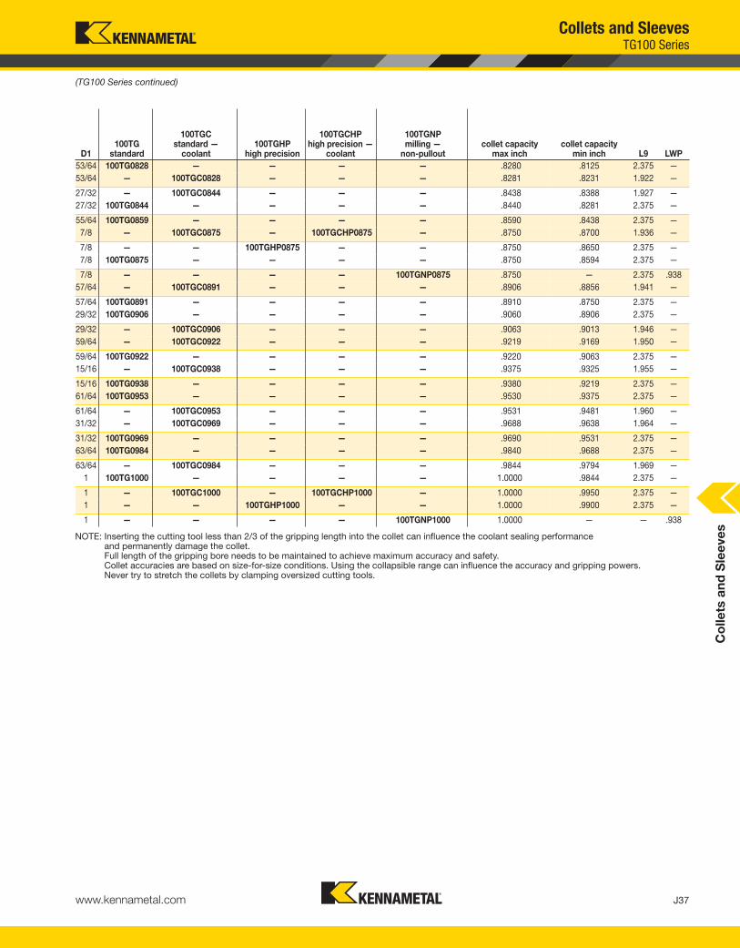
Co
lle
ts a
nd
Sle
eve
s
J37www.kennametal.com
53/64 100TG0828 — — — — .8280 .8125 2.375 —
53/64 — 100TGC0828 — — — .8281 .8231 1.922 —
27/32 — 100TGC0844 — — — .8438 .8388 1.927 —
27/32 100TG0844 — — — — .8440 .8281 2.375 —
55/64 100TG0859 — — — — .8590 .8438 2.375 —
7/8 — 100TGC0875 — 100TGCHP0875 — .8750 .8700 1.936 —
7/8 — — 100TGHP0875 — — .8750 .8650 2.375 —
7/8 100TG0875 — — — — .8750 .8594 2.375 —
7/8 — — — — 100TGNP0875 .8750 — 2.375 .938
57/64 — 100TGC0891 — — — .8906 .8856 1.941 —
57/64 100TG0891 — — — — .8910 .8750 2.375 —
29/32 100TG0906 — — — — .9060 .8906 2.375 —
29/32 — 100TGC0906 — — — .9063 .9013 1.946 —
59/64 — 100TGC0922 — — — .9219 .9169 1.950 —
59/64 100TG0922 — — — — .9220 .9063 2.375 —
15/16 — 100TGC0938 — — — .9375 .9325 1.955 —
15/16 100TG0938 — — — — .9380 .9219 2.375 —
61/64 100TG0953 — — — — .9530 .9375 2.375 —
61/64 — 100TGC0953 — — — .9531 .9481 1.960 —
31/32 — 100TGC0969 — — — .9688 .9638 1.964 —
31/32 100TG0969 — — — — .9690 .9531 2.375 —
63/64 100TG0984 — — — — .9840 .9688 2.375 —
63/64 — 100TGC0984 — — — .9844 .9794 1.969 —
1 100TG1000 — — — — 1.0000 .9844 2.375 —
1 — 100TGC1000 — 100TGCHP1000 — 1.0000 .9950 2.375 —
1 — — 100TGHP1000 — — 1.0000 .9900 2.375 —
1 — — — — 100TGNP1000 1.0000 — — .938
NOTE: Inserting the cutting tool less than 2/3 of the gripping length into the collet can influence the coolant sealing performance and permanently damage the collet. Full length of the gripping bore needs to be maintained to achieve maximum accuracy and safety.Collet accuracies are based on size-for-size conditions. Using the collapsible range can influence the accuracy and gripping powers.Never try to stretch the collets by clamping oversized cutting tools.
(TG100 Series continued)
Collets and SleevesTG100 Series
D1100TG
standard
100TGCstandard —
coolant100TGHP
high precision
100TGCHPhigh precision —
coolant
100TGNPmilling —
non-pulloutcollet capacity
max inchcollet capacity
min inch L9 LWP
KEN_TOOLINGSYSTEMS11_J036_J037.qxp:WIDIA 11:35 AM Page J37

J38 www.kennametal.com
Co
lle
ts a
nd
Sle
eve
s
catalog number series quantitydimensional
rangeincremental
division
S100TG1SET TG100 59 3/32-1 1/64
S100TG2SET TG100 30 3/32 - 1 1/32
S100TG3SET TG100 41 3/8 - 1 1/64
S100TG4SET TG100 21 3/8 - 1 1/32
catalog number series quantitydimensional
rangeincremental
division
S100TGNPSET TG100 6 3/8-1 1/8
Collets and SleevesTG100 Single-Angle Standard Collet Sets
• An economical way to purchase a group of collets.
TG Collet
TG Collet — NP
� TG100 Collet Set • Inch
� TG100 NP-Out Collet Set • Inch
KEN_TOOLINGSYSTEMS11_J038_J039.qxp:WIDIA 11:35 AM Page J38

Experience the advantages at your Authorized Kennametal Distributor or at www.kennametal.com.
www.kennametal.com
KenFeed™ MiniSmall High-Feed Milling Cutter for Machining Small and Medium Components
Roughing operations through the latest milling strategies up to 55 HRC. Specially suited for small parts or machines with lower power capacity. The KenFeed Mini delivers higher productivity with reduced tooling costs.
• Able to machine many materials and applications.
• Higher feed rates and/or HSM capabilities.
• Grade/geometry selection offers the best performance, even in hardened steel, stainless steel, and titanium materials.
• Improved tool life and MRR. Able to machine deep cavities with higher performance.
To learn more, scan here.
For instructions on how to scan, please see page xxxiii.
KEN_TOOLINGSYSTEMS11_J038_J039.qxp:WIDIA 11:35 AM Page J39

J40 www.kennametal.com
Co
lle
ts a
nd
Sle
eve
sCollets and SleevesTG100 Single-Angle Solid Tap Collets
• Rubber-filled slots seal collet for coolant-fed tool applications.
• Can be used in all standard TG collet chucks.
• Provides Tremendous Grip (3:1 advantage) and accuracy for tapping applications.
• Slot in back of collets acts as a drive for the tap square.
• Industry-standard Erickson™ single-angle collet system.
• Manufactured to DIN 6499 Class 2 accuracy; see page M103.
tap size catalog numbercolletseries D1 S10 L9
M9 & M12 100TGST090071M TG100 9,0 7,1 30,0
M10 100TGST100080M TG100 10,0 8,0 30,0
M14 100TGST110090M TG100 11,0 9,0 30,0
M16 100TGST120090M TG100 12,0 9,0 30,0
M18 100TGST140110M TG100 14,0 11,0 30,0
M20 100TGST160120M TG100 16,0 12,0 30,0
M22 & M24 100TGST180145M TG100 18,0 14,5 30,0
� TG100 Solid Tap Collet • Metric DIN and ISO
� TG100 Solid Tap Collet • Solid Tap Coolant • Inch/Metric ANSI
tap size
mm in100TGSTsolid tap
100TGSTCsolid tap —
coolantcolletseries D1 S10 L9
M3 & M3,15 & M3,5 #0-#6 & 1/8 100TGST6 — TG100 .141 .110 .141
M4 #8 & 5/32 100TGST8 — TG100 .168 .131 .168
M4,5 & M5 #10 & 3/16 100TGST10 — TG100 .194 .152 .194
— #12 & 7/32 100TGST12 — TG100 .220 .165 .220
M6 & M6,3 #14 & 1/4 100TGST025 — TG100 .255 .191 .812
— 1/16P & 1/8P(SS) 100TGST006P — TG100 .313 .234 .812
M7 & M8 5/16 100TGST031 100TGSTC031 TG100 .318 .238 .868
— 7/16 100TGST043 100TGSTC043 TG100 .323 .242 .963
M12 & M12,5 1/2 100TGST050 100TGSTC050 TG100 .367 .275 .932
M10 3/8 100TGST037 100TGSTC037 TG100 .381 .286 .900
M14 9/16 100TGST056 — TG100 .429 .322 1.087
— 1/8P(LS) 100TGST012P — TG100 .438 .328 .812
M16 5/8 100TGST062 100TGSTC062 TG100 .480 .360 1.087
M18 11/16 100TGST068 — TG100 .542 .406 1.244
(continued)
KEN_TOOLINGSYSTEMS11_J040_J041.qxp:WIDIA 11:35 AM Page J40

Co
lle
ts a
nd
Sle
eve
s
J41www.kennametal.com
(TG100 Single-Angle Solid Tap Collets continued)
Collets and SleevesTG100 Single-Angle Solid Tap Collets
— 1/4P 100TGST025P — TG100 .563 .421 .812
— 3/4 100TGST075 100TGSTC075 TG100 .590 .442 1.213
M20 13/16 100TGST081 — TG100 .652 .489 .652
— 1/2P 100TGST050P — TG100 .688 .515 .812
M22 7/8 100TGST087 — TG100 .697 .523 .697
M22 7/8 — 100TGSTC087 TG100 .697 .523 1.369
— 3/8P 100TGST037P — TG100 .700 .531 .812
M24 15/16 100TGST094 — TG100 .760 .570 .760
M25 1 — 100TGSTC100 TG100 .800 .600 1.313
M25 1 100TGST100 — TG100 .800 .600 .800
M27 1 1/16 & 1 1/8 100TGST112 — TG100 .896 .672 .896
— 3/4P 100TGST075P — TG100 .906 .679 .812
NOTE: Inserting the cutting tool less than 2/3 of the gripping length into the collet can influence the coolant sealing performance and permanently damage the collet. Full length of the gripping bore needs to be maintained to achieve maximum accuracy and safety.Collet accuracies are based on size-for-size conditions. Using the collapsible range can influence the accuracy and gripping powers.Never try to stretch the collets by clamping oversized cutting tools.
mm in100TGSTsolid tap
100TGSTCsolid tap —
coolantcolletseries D1 S10 L9
tap size
KEN_TOOLINGSYSTEMS11_J040_J041.qxp:WIDIA 11:35 AM Page J41

J42 www.kennametal.com
Co
lle
ts a
nd
Sle
eve
s
12,0 150TG120M — 12,0 11,6 44,0 —
13,0 150TG130M — 13,0 12,6 44,0 —
14,0 150TG140M — 14,0 13,6 44,0 —
14,5 150TG145M — 14,5 14,1 44,0 —
15,0 150TG150M — 15,0 14,6 54,0 —
16,0 150TG160M — 16,0 15,6 54,0 —
18,0 150TG180M — 18,0 17,6 54,0 —
19,0 150TG190M — 19,0 18,6 76,2 —
20,0 150TG200M — 20,0 19,6 76,2 —
21,0 150TG210M — 21,0 20,6 76,2 —
Collets and SleevesTG150 Series
• Provides Tremendous Grip (3:1 advantage) and accuracy for all drilling applications.
• Industry-standard Erickson™ single-angle collet system.
• 0,4mm [.016" (1/64")] range of collapse.
• Grips on back taper and margin of drill for maximum feed rates and more accurate holes.
• Manufactured to DIN 6499 Class 2 accuracy; see page M103.
TG Collet
TG Collet — NP
TG Collet
TG Collet — NP
� TG150 Series • Metric
D1150TG
standard
150TGNPstandard — non-pullout
collet capacity max mm
collet capacity min mm L9 LWP
(continued)
KEN_TOOLINGSYSTEMS11_J042_J043.qxp:WIDIA 11:35 AM Page J42

Co
lle
ts a
nd
Sle
eve
s
J43www.kennametal.com
22,0 150TG220M — 22,0 21,6 76,2 —
25,0 150TG250M — 25,0 24,6 76,2 —
25,0 — 150TGNP250M 25,0 — — 22
25,5 150TG255M — 25,5 25,1 76,2 —
26,0 150TG260M — 26,0 25,6 76,2 —
27,0 150TG270M — 27,0 26,6 76,2 —
28,0 150TG280M — 28,0 27,6 76,2 —
30,0 150TG300M — 30,0 29,6 76,2 —
32,0 150TG320M — 32,0 31,6 76,2 —
32,0 — 150TGNP320M 32,0 — — 22
34,0 150TG340M — 34,0 33,6 76,2 —
35,0 150TG350M — 35,0 34,6 76,2 —
36,0 150TG360M — 36,0 35,6 76,2 —
38,0 150TG380M — 38,0 37,6 76,2 —
40,0 150TG400M — 40,0 39,6 76,2 —
NOTE: Inserting the cutting tool less than 2/3 of the gripping length into the collet can influence the coolant sealing performance and permanently damage the collet. Full length of the gripping bore needs to be maintained to achieve maximum accuracy and safety.Collet accuracies are based on size-for-size conditions. Using the collapsible range can influence the accuracy and gripping powers.Never try to stretch the collets by clamping oversized cutting tools.
(TG150 Series continued)
Collets and SleevesTG150 Series
D1150TG
standard
150TGNPstandard — non-pullout
collet capacity max mm
collet capacity min mm L9 LWP
KEN_TOOLINGSYSTEMS11_J042_J043.qxp:WIDIA 11:35 AM Page J43

J44 www.kennametal.com
Co
lle
ts a
nd
Sle
eve
s
D1150TG
standard
150TGCHPhigh precision —
coolant
150TGNPmilling —
non-pulloutcollet capacity
max inchcollet capacity
min inch L9 LWP
3/8 150TG0375 — — .3750 .3594 2.000 —
25/64 150TG0391 — — .3906 .3750 2.000 —
13/32 150TG0406 — — .4063 .3906 2.000 —
27/64 150TG0422 — — .4219 .4063 2.000 —
7/16 150TG0438 — — .4375 .4219 2.000 —
29/64 150TG0453 — — .4531 .4375 2.000 —
15/32 150TG0468 — — .4688 .4531 2.000 —
31/64 150TG0484 — — .4844 .4688 2.000 —
1/2 150TG0500 — — .5000 .4844 2.560 —
1/2 — — 150TGNP0500 .5000 — — .828
33/64 150TG0516 — — .5156 .5000 2.560 —
17/32 150TG0531 — — .5313 .5156 2.560 —
Collets and SleevesTG150 Series
• Provides Tremendous Grip (3:1 advantage) and accuracy for all drilling applications.
• Industry-standard Erickson™ single-angle collet system.
• 150TG 0,4mm [.016" (1/64)] range of collapse.
• 150TGCHP and 150TGNP 0,13mm (.005") range of collapse.
• Grips on back taper and margin of drill for maximum feed rates and more accurate holes.
• Manufactured to DIN 6499 Class 2 accuracy; see page M103.
• HP design manufactured to DIN 6499 class/accuracy.
TG Collet TG Collet — NP
TG ColletTG Collet — NP
� TG150 Series • Inch
(continued)
TG Collet — Coolant (Bonded)
TG Collet — Coolant (Bonded)
KEN_TOOLINGSYSTEMS11_J044_J045.qxp:WIDIA 11:35 AM Page J44

Co
lle
ts a
nd
Sle
eve
s
J45www.kennametal.com
35/64 150TG0547 — — .5469 .5313 2.560 —
9/16 150TG0562 — — .5625 .5469 2.560 —
37/64 150TG0578 — — .5781 .5625 2.560 —
19/32 150TG0594 — — .5938 .5781 2.560 —
39/64 150TG0609 — — .6094 .5938 2.560 —
5/8 150TG0625 — — .6250 .6094 2.560 —
5/8 — — 150TGNP0625 .6250 — — .875
41/64 150TG0641 — — .6406 .6250 2.560 —
21/32 150TG0656 — — .6563 .6406 2.560 —
43/64 150TG0672 — — .6719 .6563 2.560 —
11/16 150TG0688 — — .6875 .6719 2.560 —
45/64 150TG0703 — — .7031 .6875 2.560 —
23/32 150TG0719 — — .7188 .7031 2.560 —
47/64 150TG0734 — — .7344 .7188 2.560 —
3/4 150TG0750 — — .7500 .7344 2.560 —
3/4 — — 150TGNP0750 .7500 — — .938
49/64 150TG0766 — — .7656 .7500 2.560 —
25/32 150TG0781 — — .7813 .7656 2.560 —
51/64 150TG0797 — — .7969 .7813 2.560 —
13/16 150TG0812 — — .8125 .7969 2.560 —
53/64 150TG0828 — — .8281 .8125 2.560 —
27/32 150TG0844 — — .8438 .8281 2.560 —
55/64 150TG0859 — — .8594 .8438 2.560 —
7/8 150TG0875 — — .8750 .8594 2.560 —
7/8 — — 150TGNP0875 .8750 — — .938
57/64 150TG0891 — — .8906 .8750 2.560 —
29/32 150TG0906 — — .9063 .8906 2.560 —
59/64 150TG0922 — — .9219 .9063 2.560 —
15/16 150TG0938 — — .9375 .9219 2.560 —
61/64 150TG0953 — — .9531 .9375 2.560 —
31/32 150TG0969 — — .9688 .9531 2.560 —
63/64 150TG0984 — — .9844 .9688 2.560 —
1 150TG1000 — — 1.0000 .9844 2.560 —
1 — 150TGCHP1000 — — — — —
(TG150 Series continued)
(continued)
Collets and SleevesTG150 Series
1 — — 150TGNP1000 1.0000 — — 1.063
1 1/64 150TG1016 — — 1.0156 1.0000 2.560 —
1 1/32 150TG1031 — — 1.0313 1.0156 2.560 —
1 3/64 150TG1047 — — 1.0469 1.0313 2.560 —
1 1/16 150TG1062 — — 1.0625 1.0469 2.560 —
1 5/64 150TG1078 — — 1.0781 1.0625 2.560 —
1 3/32 150TG1094 — — 1.0938 1.0781 2.560 —
1 7/64 150TG1109 — — 1.1094 1.0938 2.560 —
1 9/64 150TG1141 — — 1.1200 1.1094 2.560 —
1 1/8 150TG1125 — — 1.1250 1.1200 2.560 —
1 5/32 150TG1156 — — 1.1563 1.1250 2.560 —
1 11/64 150TG1172 — — 1.1719 1.1563 2.560 —
1 3/16 150TG1187 — — 1.1875 1.1719 2.560 —
1 13/64 150TG1203 — — 1.2031 1.1875 2.560 —
D1150TG
standard
150TGCHPhigh precision —
coolant
150TGNPmilling —
non-pulloutcollet capacity
max inchcollet capacity
min inch L9 LWP
KEN_TOOLINGSYSTEMS11_J044_J045.qxp:WIDIA 11:36 AM Page J45
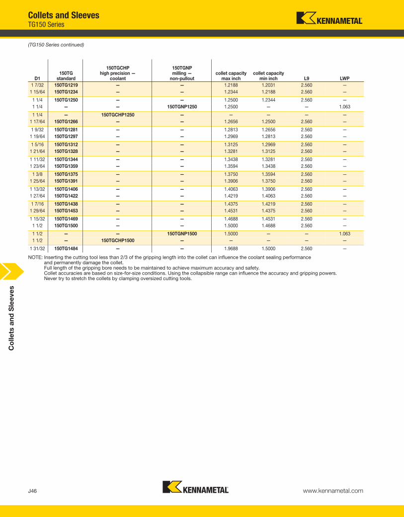
J46 www.kennametal.com
Co
lle
ts a
nd
Sle
eve
s
1 7/32 150TG1219 — — 1.2188 1.2031 2.560 —
1 15/64 150TG1234 — — 1.2344 1.2188 2.560 —
1 1/4 150TG1250 — — 1.2500 1.2344 2.560 —
1 1/4 — — 150TGNP1250 1.2500 — — 1.063
1 1/4 — 150TGCHP1250 — — — — —
1 17/64 150TG1266 — — 1.2656 1.2500 2.560 —
1 9/32 150TG1281 — — 1.2813 1.2656 2.560 —
1 19/64 150TG1297 — — 1.2969 1.2813 2.560 —
1 5/16 150TG1312 — — 1.3125 1.2969 2.560 —
1 21/64 150TG1328 — — 1.3281 1.3125 2.560 —
1 11/32 150TG1344 — — 1.3438 1.3281 2.560 —
1 23/64 150TG1359 — — 1.3594 1.3438 2.560 —
1 3/8 150TG1375 — — 1.3750 1.3594 2.560 —
1 25/64 150TG1391 — — 1.3906 1.3750 2.560 —
1 13/32 150TG1406 — — 1.4063 1.3906 2.560 —
1 27/64 150TG1422 — — 1.4219 1.4063 2.560 —
1 7/16 150TG1438 — — 1.4375 1.4219 2.560 —
1 29/64 150TG1453 — — 1.4531 1.4375 2.560 —
1 15/32 150TG1469 — — 1.4688 1.4531 2.560 —
1 1/2 150TG1500 — — 1.5000 1.4688 2.560 —
1 1/2 — — 150TGNP1500 1.5000 — — 1.063
1 1/2 — 150TGCHP1500 — — — — —
1 31/32 150TG1484 — — 1.9688 1.5000 2.560 —
NOTE: Inserting the cutting tool less than 2/3 of the gripping length into the collet can influence the coolant sealing performance and permanently damage the collet. Full length of the gripping bore needs to be maintained to achieve maximum accuracy and safety.Collet accuracies are based on size-for-size conditions. Using the collapsible range can influence the accuracy and gripping powers.Never try to stretch the collets by clamping oversized cutting tools.
(TG150 Series continued)
Collets and SleevesTG150 Series
D1150TG
standard
150TGCHPhigh precision —
coolant
150TGNPmilling —
non-pulloutcollet capacity
max inchcollet capacity
min inch L9 LWP
KEN_TOOLINGSYSTEMS11_J046_J047.qxp:WIDIA 11:36 AM Page J46

Co
lle
ts a
nd
Sle
eve
s
J47www.kennametal.com
catalog number series quantitydimensional
rangeincremental
division
S150TG1SET TG150 65 1/2 -1 1/2 1/64
S150TG2SET TG150 33 1/2 - 1 1/2 1/32
S150TG4SET TG150 25 3/4 -1 1/2 1/32
catalog number series quantitydimensional
rangeincremental
division
S150TGNPSET TG150 7 1/2 - 1 1/2 1/8 (1/2-1) & 1/4 (1 1/4-1 1/2)
Collets and SleevesTG150 Single-Angle Standard Collet Sets
• An economical way to purchase a group of collets.
TG Collet
TG Collet — NP
� TG150 Collet Set • Inch
� TG150 NP-Out Collet Set • Inch
� TG150 Collet Set • Metric
catalog number series quantitydimensional
rangeincremental
division
150TGS000M TG150 3 25mm - 40mm 25 & 32 & 40
KEN_TOOLINGSYSTEMS11_J046_J047.qxp:WIDIA 11:36 AM Page J47

J48 www.kennametal.com
Co
lle
ts a
nd
Sle
eve
s
tap size
mm in150TGSTsolid tap
colletseries D1 S10 L9
— 3/4 150TGST075 TG150 .590 .442 1.213
— 1/2P 150TGST050P TG150 .688 .515 .812
— 3/8P 150TGST037P TG150 .700 .531 .812
M25 1 150TGST100 TG150 .800 .600 1.463
M27 1 1/16 & 1 1/8 150TGST112 TG150 .896 .672 1.650
— 3/4P 150TGST075P TG150 .906 .679 .906
M30 1 3/16 & 1 1/4 150TGST125 TG150 1.021 .766 1.750
M33 1 5/16 & 1 3/8 150TGST137 TG150 1.108 .831 1.687
— 1P 150TGST100P TG150 1.125 2.142 .906
M36 1 7/16 & 1 1/2 150TGST150 TG150 1.233 .925 1.625
M39 1 5/8 150TGST162 TG150 1.305 .979 1.625
— 1 1/4P 150TGST125P TG150 1.313 2.085 .963
M42 1 3/4 150TGST175 TG150 1.430 1.072 1.500
— 1 1/2P 150TGST150P TG150 1.500 1.898 1.150
Collets and SleevesTG150 Single-Angle Solid Tap Collets
• Can be used in all standard TG collet chucks.
• Provides Tremendous Grip (3:1 advantage) and accuracyfor tapping applications.
• Slot in back of collets acts as a drive for the tap square.
• Industry-standard Erickson™ single-angle collet system.
� TG150 Solid Tap Collet • Metric DIN and ISO
*** Metric DIN and ISO only available in TG50 and TG100 series ***
� TG150 Solid Tap Collet • Inch/Metric ANSI
NOTE: Inserting the cutting tool less than 2/3 of the gripping length into the collet can influence the coolant sealing performance and permanently damage the collet. Full length of the gripping bore needs to be maintained to achieve maximum accuracy and safety.Collet accuracies are based on size-for-size conditions. Using the collapsible range can influence the accuracy and gripping powers.Never try to stretch the collets by clamping oversized cutting tools.
KEN_TOOLINGSYSTEMS11_J048_J049.qxp:WIDIA 11:36 AM Page J48

Experience the advantages at your Authorized Kennametal Distributor or at www.kennametal.com.
www.kennametal.com
The
KennametalSolution
No matter how small or large your project.• Whether it’s a single tailored tool or the development of a comprehensive manufacturing process,
Kennametal’s team can manage the development, personnel training, and successful
implementation of the complete solution.
Regardless of where you’re located, Kennametal is everywhere you are.• With Kennametal’s team, you receive globally coordinated manufacturing, process development,
implementation, and optimization support and key alliances with machine tool builders and other
leading technology manufacturers that ensure a complete solution.
Kennametal Global Engineered Solutions. Coordinated global
resources with world-class manufacturing, process development,
and implementation capabilities.
KEN_TOOLINGSYSTEMS11_J048_J049.qxp:WIDIA 11:36 AM Page J49

J50 www.kennametal.com
ER DIN 6499 Single-Angle Collets
Primary Application
The standard ER Collets are manufactured according to DIN 6499-B (16° inclusive angle) standard and are available in a variety of styles, ER8, ER11, ER16, ER20, ER25, ER32, and ER40, with sizes ranging from 0,5–26mm (.0197–1.0000"). Applications of light end milling, drilling, tapping, reaming, and boring solution are applicable.
Features and Benefits
• DIN 6499 Class 2 accuracy.
• 16° inclusive taper angle taper for approximately 2:1 grip.
• Dedicated versions for tapping — driving off the square of the tap.
16° inclusive angle.
KEN_TOOLINGSYSTEMS11_J050_J051.qxp:WIDIA 11:36 AM Page J50
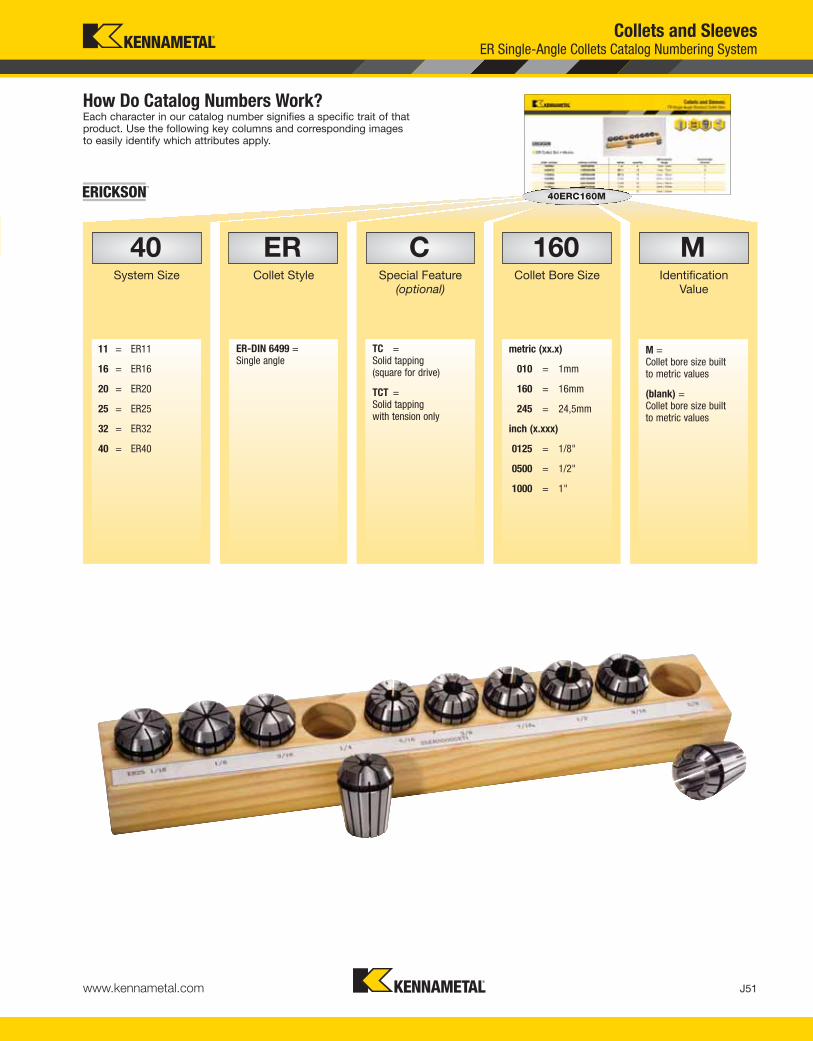
J51www.kennametal.com
How Do Catalog Numbers Work?Each character in our catalog number signifies a specific trait of thatproduct. Use the following key columns and corresponding imagesto easily identify which attributes apply.
Collets and SleevesER Single-Angle Collets Catalog Numbering System
C
ER-DIN 6499 =Single angle
M =Collet bore size built to metric values
(blank) =Collet bore size built to metric values
TC =Solid tapping (square for drive)
TCT =Solid tapping with tension only
11 = ER11
16 = ER16
20 = ER20
25 = ER25
32 = ER32
40 = ER40
metric (xx.x)
010 = 1mm
160 = 16mm
245 = 24,5mm
inch (x.xxx)
0125 = 1/8"
0500 = 1/2"
1000 = 1"
Special Feature(optional)
ERCollet Style
40System Size
MIdentification
Value
160Collet Bore Size
40ERC160M
KEN_TOOLINGSYSTEMS11_J050_J051.qxp:WIDIA 11:36 AM Page J51

J52 www.kennametal.com
Co
lle
ts a
nd
Sle
eve
s
ERTC • Single-Angle Tap Collet• Designed to grip taps on shank and square to eliminate slippage.• Fits all standard ER-style collet chucks.• 0,13mm (.005") range of collapse.
ERTCT • Single-Angle Tap Collet with Axial Compensation• Designed to grip taps on shank and square to eliminate slippage.• Tension only, cost effective solution for machines that require axial compensation for tapping.• Fits all standard ER-style collet chucks.
ER • Single Angle• Provides good grip and accuracy for all drilling applications.• Wide clamping range.• Available in both inch and metric bores.• 1mm (.040") range of collapse.• Manufactured to DIN 6499.• Accuracy to DIN 6499 Class 2.
Collets and SleevesER Single-Angle Collets
KEN_TOOLINGSYSTEMS11_J052_J053.qxp:WIDIA 11:36 AM Page J52

Visit www.kennametal.com or contact your local Authorized Kennametal Distributor.
www.kennametal.com
HARVI II™
A New Dimension
• Best suited for applications in the aerospace, medical, die and mold, automotive, and general engineering markets.
• Outstanding performance in stainless steel, titanium, INCONEL®, and other high-temperature alloys and steels.
• Increased metal removal rates in roughing and finishing operations.
The next generation high-performance end mill, HARVI II dramatically
improves metal removal rates without reducing tool life.
To learn more, scan here.
For instructions on how to scan, please see page xxxiii.
KEN_TOOLINGSYSTEMS11_J052_J053.qxp:WIDIA 11:36 AM Page J53

J54 www.kennametal.com
Co
llets
and
Sle
eves
Collets and SleevesER Single-Angle Standard Collets
• Provides approximately 2:1 grip advantage.• Wide clamping range for all drilling applications.• ER8 and ER11 0,5mm (.020") range of collapse.• ER16, ER20, ER25, ER32, and ER40 1mm (.040") range of collapse.• Available in both metric and inch sizes.• Manufactured to DIN 6499 Class 2 accuracy; see page M103.
� ER Collets • Metric
(continued)
D1
ER8D2 = 8,5mmL = 13,5mm
ER11D2 = 11,5mm
L = 18mm
ER16D2 = 17mmL = 27,5mm
ER20D2 = 21mmL = 31,5mm
ER25D2 = 26mmL = 34mm
ER32D2 = 33mmL = 40mm
ER40D2 = 41mmL = 46mm
collet capacity max mm
collet capacity min mm
1,0 8ER010M 11ER010M 16ER010M 20ER010M — — — 1,00 0,501,5 8ER015M 11ER015M 16ER015M — — — — 1,50 1,00
2,0 — — 16ER020M 20ER020M 25ER020M — — 2,00 1,002,0 8ER020M 11ER020M — — — — — 2,00 1,50
2,5 — — 16ER025M — — — — 2,50 1,502,5 8ER025M 11ER025M — — — — — 2,50 2,00
3,0 — — 16ER030M 20ER030M 25ER030M 32ER030M — 3,00 2,003,0 8ER030M 11ER030M — — — — — 3,00 2,50
3,5 — — 16ER035M — — — — 3,50 2,503,5 8ER035M 11ER035M — — — — — 3,50 3,00
4,0 — — 16ER040M 20ER040M 25ER040M 32ER040M 40ER040M 4,00 3,004,0 8ER040M 11ER040M — — — — — 4,00 3,50
4,5 — — 16ER045M — — — — 4,50 3,504,5 8ER045M 11ER045M — — — — — 4,50 4,00
5,0 — — 16ER050M 20ER050M 25ER050M 32ER050M 40ER050M 5,00 4,005,0 8ER050M 11ER050M — — — — — 5,00 4,50
5,5 — — 16ER055M — — — — 5,50 4,505,5 — 11ER055M — — — — — 5,50 5,00
6,0 — — 16ER060M 20ER060M 25ER060M 32ER060M 40ER060M 6,00 5,006,0 — 11ER060M — — — — — 6,00 5,50
6,5 — — 16ER065M — — — — 6,50 5,506,5 — 11ER065M — — — — — 6,50 6,00
7,0 — — 16ER070M 20ER070M 25ER070M 32ER070M 40ER070M 7,00 6,007,0 — 11ER070M — — — — — 7,00
7,5 — — 16ER075M — — — — 7,50 6,508,0 — — 16ER080M 20ER080M 25ER080M 32ER080M 40ER080M 8,00 7,00
6,50
KEN_TOOLINGSYSTEMS11_J054_J055.qxp:WIDIA 2:11 PM Page J54

Co
llets
and
Sle
eves
J55www.kennametal.com
Collets and SleevesER Single-Angle Standard Collets
(continued)
(ER Single-Angle Standard Collets continued)
8,5 — — 16ER085M — — — — 8,50 7,509,0 — — 16ER090M 20ER090M 25ER090M 32ER090M 40ER090M 9,00 8,00
9,5 — — 16ER095M — — — — 9,50 8,5010,0 — — 16ER100M 20ER100M 25ER100M 32ER100M 40ER100M 10,00 9,00
11,0 — — — 20ER110M 25ER110M 32ER110M 40ER110M 11,00 10,0012,0 — — — 20ER120M 25ER120M 32ER120M 40ER120M 12,00 11,00
13,0 — — — 20ER130M 25ER130M 32ER130M 40ER130M 13,00 12,0014,0 — — — — 25ER140M 32ER140M 40ER140M 14,00 13,00
15,0 — — — — 25ER150M 32ER150M 40ER150M 15,00 14,0016,0 — — — — 25ER160M 32ER160M 40ER160M 16,00 15,00
17,0 — — — — — 32ER170M 40ER170M 17,00 16,0018,0 — — — — — 32ER180M 40ER180M 18,00 17,00
19,0 — — — — — 32ER190M 40ER190M 19,00 18,0020,0 — — — — — 32ER200M 40ER200M 20,00 19,00
21,0 — — — — — — 40ER210M 21,00 20,0022,0 — — — — — — 40ER220M 22,00 21,00
23,0 — — — — — — 40ER230M 23,00 22,0024,0 — — — — — — 40ER240M 24,00 23,00
25,0 — — — — — — 40ER250M 25,00 24,0026,0 — — — — — — 40ER260M 26,00 25,00
D1
ER8D2 = 8,5mmL = 13,5mm
ER11D2 = 11,5mm
L = 18mm
ER16D2 = 17mmL = 27,5mm
ER20D2 = 21mmL = 31,5mm
ER25D2 = 26mmL = 34mm
ER32D2 = 33mmL = 40mm
ER40D2 = 41mmL = 46mm
collet capacity max mm
collet capacity min mm
KEN_TOOLINGSYSTEMS11_J054_J055.qxp:WIDIA 2:11 PM Page J55

J56 www.kennametal.com
Co
lle
ts a
nd
Sle
eve
s
NOTE: Inserting the cutting tool less than 2/3 the gripping length into the collet can permanently damage the collet. Full length of the gripping bore must be maintained to achieve maximum accuracy and safety.Collet accuracies are based on size-for-size conditions. Never try to stretch the collets by clamping oversized cutting tools.
Collets and SleevesER Single-Angle Standard Collets
(ER Single-Angle Standard Collets continued)
� ER Collets • Inch
D1
ER16D2 = .669L = 1.083
ER20D2 = .827L = 1.240
ER25D2 = 1.024L = 1.339
ER32D2 = 1.299L = 1.575
ER40D2 = 1.614L = 1.811
collet capacitymax inch
collet capacity min inch
1/16 16ER0062 20ER0062 25ER0062 — — .0625 .0425
3/32 — 20ER0094 — — — .0938 .0538
3/32 16ER0094 — 25ER0094 — — .0938 .0738
1/8 16ER0125 20ER0125 25ER0125 32ER0125 40ER0125 .1250 .0850
5/32 16ER0156 20ER0156 25ER0156 32ER0156 40ER0156 .1563 .1163
3/16 16ER0188 20ER0188 25ER0188 32ER0188 40ER0188 .1875 .1475
7/32 16ER0219 20ER0219 25ER0219 32ER0219 40ER0219 .2188 .1788
1/4 16ER0250 20ER0250 25ER0250 32ER0250 40ER0250 .2500 .2100
9/32 16ER0281 20ER0281 25ER0281 32ER0281 40ER0281 .2813 .2413
5/16 16ER0312 20ER0312 25ER0312 32ER0312 40ER0312 .3125 .2725
11/32 16ER0344 20ER0344 25ER0344 32ER0344 40ER0344 .3438 .3038
3/8 16ER0375 20ER0375 25ER0375 32ER0375 40ER0375 .3750 .3350
13/32 16ER0406 20ER0406 25ER0406 32ER0406 40ER0406 .4063 .3663
7/16 — 20ER0438 25ER0438 32ER0438 40ER0438 .4375 .3975
15/32 — 20ER0469 25ER0469 32ER0469 40ER0469 .4688 .4288
1/2 — 20ER0500 25ER0500 32ER0500 40ER0500 .5000 .4600
17/32 — — 25ER0531 32ER0531 40ER0531 .5313 .4913
9/16 — — — 32ER0562 40ER0562 .5625 .5225
9/16 — — 25ER0562 — — .5626 .5225
19/32 — — 25ER0594 32ER0594 40ER0594 .5938 .5538
5/8 — — 25ER0625 32ER0625 40ER0625 .6250 .5850
21/32 — — — 32ER0656 40ER0656 .6563 .6163
11/16 — — — 32ER0688 40ER0688 .6875 .6475
23/32 — — — 32ER0719 40ER0719 .7188 .6788
3/4 — — — 32ER0750 40ER0750 .7500 .7100
25/32 — — — 32ER0781 40ER0781 .7813 .7413
13/16 — — — 32ER0812 40ER0812 .8125 .7725
27/32 — — — — 40ER0844 .8438 .8038
7/8 — — — — 40ER0875 .8750 .8350
29/32 — — — — 40ER0906 .9063 .8663
15/16 — — — — 40ER0938 .9375 .8975
31/32 — — — — 40ER0969 .9688 .9288
1 — — — — 40ER1000 1.0000 .9600
KEN_TOOLINGSYSTEMS11_J056_J057.qxp:WIDIA 11:37 AM Page J56

Co
lle
ts a
nd
Sle
eve
s
J57www.kennametal.com
order number catalog number series quantitydimensional
rangeincremental
division
1025864 8ERS000M ER8 9 1mm - 5mm .5
1020872 11ERS000M ER11 13 1mm - 7mm .5
1135892 16ERS000M ER16 10 1mm - 10mm 1
1025865 20ERS000M ER20 12 2mm - 13mm 1
1123858 25ERS000M ER25 15 2mm - 16mm 1
1135911 32ERS000M ER32 18 3mm - 20mm 1
1126252 40ERS000M ER40 23 4mm - 26mm 1
order number catalog number series quantitydimensional
rangeincremental
division
2269968 16ERS000SET2 ER16 12 1/16 - 13/32 1/32
2269969 20ERS000SET1 ER20 8 1/16 - 1/2 1/16
2269970 20ERS000SET2 ER20 15 1/16 - 1/2 1/32
2269971 25ERS000SET1 ER25 10 1/16 - 5/8 1/16
2269972 25ERS000SET2 ER25 19 1/16 - 5/8 1/32
2269973 32ERS000SET1 ER32 12 1/8 - 13/16 1/16
2269974 32ERS000SET2 ER32 23 1/8 - 13/16 1/32
2269975 40ERS000SET1 ER40 15 1/8 - 1 1/16
2269976 40ERS000SET2 ER40 29 1/8 - 1 1/32
Collets and SleevesER Single-Angle Standard Collet Sets
• An economical way to purchase a set of collets.
� ER Collet Set • Metric
� ER Collet Set • Inch
NOTE: ER collet sets come complete with protective tray.
KEN_TOOLINGSYSTEMS11_J056_J057.qxp:WIDIA 11:37 AM Page J57

J58 www.kennametal.com
Co
lle
ts a
nd
Sle
eve
s
tap size
ER16D2 = 17mmL = 27,5mm
ER20D2 = 21mmL = 31,5mm
ER25D2 = 26mmL = 34mm
ER32D2 = 33mmL = 40mm
ER40D2 = 41mmL = 46mm D1 S10 L9
M4 & M6 16ERTC045034M 20ERTC045034M 25ERTC045034M 32ERTC045034M — 4,5 3,4 18
— 16ERTC055043M 20ERTC055043M 25ERTC055043M 32ERTC055043M — 5,5 4,3 18
M5 & M6 & M7 & M8 16ERTC060049M 20ERTC060049M 25ERTC060049M 32ERTC060049M — 6,0 4,9 18
M10 16ERTC070055M 20ERTC070055M 25ERTC070055M 32ERTC070055M 40ERTC070055M 7,0 5,5 18
M8 16ERTC080062M 20ERTC080062M 25ERTC080062M 32ERTC080062M 40ERTC080062M 8,0 6,2 22
M12 16ERTC090070M 20ERTC090070M 25ERTC090070M 32ERTC090070M 40ERTC090070M 9,0 7,0 22
M10 — 20ERTC100080M 25ERTC100080M 32ERTC100080M 40ERTC100080M 10,0 8,0 25
M14 — 20ERTC110090M 25ERTC110090M 32ERTC110090M 40ERTC110090M 11,0 9,0 25
M16 — — 25ERTC120090M 32ERTC120090M 40ERTC120090M 12,0 9,0 25
M18 — — — 32ERTC140110M 40ERTC140110M 14,0 11,0 25
— — — 25ERTC140110M — — 14,0 11,0 25
M20 — — — 32ERTC160120M — 16,0 12,0 25
— — — 25ERTC160120M — — 16,0 12,0 25
M20 — — — — 40ERTC160120M 16,0 12,0 25
M22 & M24 — — — 32ERTC180145M 40ERTC180145M 18,0 14,5 25
M27 & M30 — — — 32ERTC200160M 40ERTC200160M 20,0 16,0 28
M30 — — — — 40ERTC220180M 22,0 18,0 28
Collets and SleevesER Single-Angle Solid Tap Collets
• Square in back of collet acts as a drive for the tap square.
• Can be used in all standard ER collet chucks.
• Available in metric and inch sizes.
� ER Solid Tap Collet • Metric DIN and ISO
(continued)
KEN_TOOLINGSYSTEMS11_J058_J059.qxp:WIDIA 11:37 AM Page J58

Co
lle
ts a
nd
Sle
eve
s
J59www.kennametal.com
� ER Solid Tap Collet • Inch/Metric ANSI
NOTE: Inserting the cutting tool less than 2/3 the gripping length into the collet can permanently damage the collet. Full length of the gripping bore must be maintained to achieve maximum accuracy and safety.Collet accuracies are based on size-for-size conditions. Using the collapsible range can influence the accuracy and gripping powers.Never try to stretch the collets by clamping oversized cutting tools.
Collets and SleevesER Single-Angle Solid Tap Collets
tap size
mm in
ER16D2 = .669L = 1.083
ER20D2 = .827L = 1.240
ER25D2 = 1.024L = 1.339
ER32D2 = 1.299L = 1.575
ER40D2 = 1.614L = 1.811 D1 S10 L9
M4 8 & 5/32 16ERTC8 20ERTC8 25ERTC8 32ERTC8 — .168 .131 .710
M4,5 & M5 10 & 3/16 16ERTC10 20ERTC10 25ERTC10 32ERTC10 — .194 .152 .710
— 12 & 7/32 16ERTC12 20ERTC12 25ERTC12 32ERTC12 — .220 .165 .710
M6 & M6,3 14 & 1/4 16ERTC025 20ERTC025 25ERTC025 32ERTC025 40ERTC025 .255 .191 .710
M7 & M8 5/16 — 20ERTC031 25ERTC031 32ERTC031 40ERTC031 .318 .238 .866
— 7/16 — 20ERTC043 25ERTC043 32ERTC043 40ERTC043 .323 .242 .866
M12 & M12,5 1/2 — 20ERTC050 25ERTC050 32ERTC050 40ERTC050 .367 .275 .866
M10 3/8 — 20ERTC037 25ERTC037 32ERTC037 40ERTC037 .381 .286 .866
M14 9/16 — — 25ERTC056 32ERTC056 40ERTC056 .429 .322 .984
M16 5/8 — — 25ERTC062 32ERTC062 40ERTC062 .480 .360 .984
M18 11/16 — — — 32ERTC069 40ERTC069 .542 .406 .984
— 3/4 — — — 32ERTC075 — .590 .422 .984
— 3/4 — — — — 40ERTC075 .590 .442 .984
M20 13/16 — — — 32ERTC081 40ERTC081 .652 .489 .984
M22 7/8 — — — — 40ERTC087 .697 .523 .984
M24 15/16 — — — — 40ERTC093 .760 .570 1.100
M25 1 — — — — 40ERTC100 .800 .600 1.100
(ER Single-Angle Solid Tap Collets continued)
KEN_TOOLINGSYSTEMS11_J058_J059.qxp:WIDIA 11:37 AM Page J59

J60 www.kennametal.com
Co
lle
ts a
nd
Sle
eve
sCollets and SleevesER16 Single-Angle Tension Tap Collets
• Tension feature for applications that needsynchronized tapping.
• Adjustable screws in back of collet act as a drive for the tap square.
• Can be used in all standard ER collet chucks.
• Available in inch sizes.
� ER T-Only Tap Collet • Inch/Metric ANSI
NOTE: 12ERTCT6 fits ER11 chucks.Full length of the gripping bore must be maintained to achieve maximum accuracy and safety.
tap size D1mm in
ER12D2 = 11,4mmL = 21,5mm
ER16D2 = 17mmL = 27,5mm
ER20D2 = 21mmL = 31,5mm
ER25D2 = 26mmL = 34mm
ER32D2 = 33mmL = 40mm
ER40D2 = 41mmL = 46mm mm in
M3 & M3,15 & M3,5 #0-#6 & 1/8 12ERTCT6 16ERTCT6 20ERTCT6 25ERTCT6 — — 3,58 .141
M4 #8 & 5/32 — 16ERTCT8 20ERTCT8 25ERTCT8 32ERTCT8 — 4,27 .168
M4,5 & M5 #10 & 3/16 — 16ERTCT10 20ERTCT10 25ERTCT10 32ERTCT10 — 4,93 .194
— #12 & 7/32 — — 20ERTCT12 25ERTCT12 32ERTCT12 — 5,59 .220
M6 & M6,3 #14 & 1/4 — — 20ERTCT025 25ERTCT025 32ERTCT025 40ERTCT025 6,48 .255
M7 & M8 5/16 — — — 25ERTCT031 32ERTCT031 40ERTCT031 8,08 .318
— 7/16 — — — 25ERTCT043 32ERTCT043 40ERTCT043 8,20 .323
M12 & M12,5 1/2 — — — 25ERTCT050 32ERTCT050 40ERTCT050 9,32 .367
M10 3/8 — — — 25ERTCT037 32ERTCT037 40ERTCT037 9,68 .381
M14 9/16 — — — — 32ERTCT056 40ERTCT056 10,90 .429
— 1/8P(LS) — — — — 32ERTCT012P — 11,10 .437
M16 5/8 — — — — 32ERTCT062 40ERTCT062 12,19 .480
M18 11/16 — — — — — 40ERTCT069 13,77 .542
— 3/4 — — — — — 40ERTCT075 14,99 .590
M20 13/16 — — — — — 40ERTCT081 16,56 .652
M22 7/8 — — — — — 40ERTCT087 17,70 .697
KEN_TOOLINGSYSTEMS11_J060_J061.qxp:WIDIA 11:37 AM Page J60

J61
Experience the advantages at your Authorized Kennametal Distributor or at www.kennametal.com.
www.kennametal.com
Solid Carbide TF Drills
B/K 105 Solid Carbide Drills are ideal for high metal removal rates and excellent hole quality in aluminum
as well as in short-hole titanium applications.
Three Cutting Edges
• Higher feed rates than with two-edged drills.
Three-Flute Design
• Rapid chip evacuation.
• Three-margin lands deliver better hole quality
and straightness than two-flute drills.
Wear-Resistant Carbide Grade
• High tool life in abrasive materials such
as aluminum die cast alloys.
Customization
• Intermediate diameters available as semi-standards.
• Length variations and step drills available
as customized solutions.
KEN_TOOLINGSYSTEMS11_J060_J061.qxp:WIDIA 11:37 AM Page J61

J62 www.kennametal.com
ERICKSON™ • DA Double-Angle Collets
Primary Application
DA – Double-Angle Collets are well-known in the industry as an economical collet system allowing reaching in to areas where other systems have clearance issues. These collets are manufactured according to the original ERICKSON standard styles, DA000, DA100, DA180, DA200, and DA300, with clamping sizes ranging from 0,5–20mm (.0197–.7500"). They are ideal for end milling, drilling, tapping, reaming, and boring solutions.
Features and Benefits
• Original ERICKSON standard.
• Versatile double-angle design providing approximately 1:1 grip.
• Bonded style available for through-coolant applications.
• Non-pullout style to captivate Weldon®-style end mills.
• Dedicated versions for tapping — driving off the square of the tap.
Double angle.
KEN_TOOLINGSYSTEMS11_J062_J063.qxp:WIDIA 11:37 AM Page J62
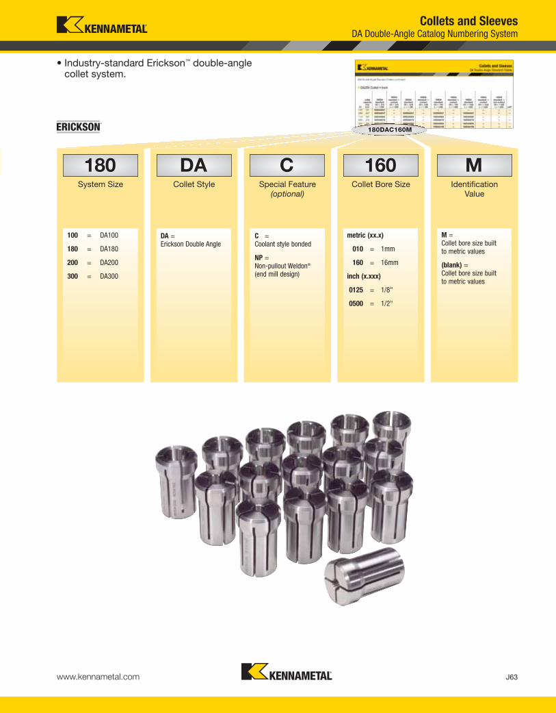
J63www.kennametal.com
• Industry-standard Erickson™ double-angle collet system.
Collets and SleevesDA Double-Angle Catalog Numbering System
C
DA =Erickson Double Angle
M =Collet bore size built to metric values
(blank) =Collet bore size built to metric values
C =Coolant style bonded
NP =Non-pullout Weldon®
(end mill design)
100 = DA100
180 = DA180
200 = DA200
300 = DA300
metric (xx.x)
010 = 1mm
160 = 16mm
inch (x.xxx)
0125 = 1/8"
0500 = 1/2"
Special Feature(optional)
DACollet Style
180System Size
MIdentification
Value
160Collet Bore Size
180DAC160M
KEN_TOOLINGSYSTEMS11_J062_J063.qxp:WIDIA 11:37 AM Page J63

Co
llets
and
Sle
eves
J64 www.kennametal.com
DA Double-Angle Collets
DAC • Double-Angle Coolant• Rubber-filled slots seal coolant-fed tool applications.• Suitable for coolant pressure up to 70 bar (1000 psi).• Fits all standard DA-style collet chucks.• 0,13mm (.005") range of collapse.
DANP • Double-Angle Non-Pullout, Weldon® Style• Designed to grip end mills with Weldon-style shanks.• Positive retention and drive provided by drive wedge in collet.• Eliminates inaccuracy created by solid end mill adapters.• Fits all standard DA-style collet chucks.• 0,13mm (.005") range of collapse.
DA-J, K, & L • Double-Angle Solid Tap• Provides positive drive for taps.
DA • Double Angle• 0,8mm [.031" (1/32")] maximum range of collapse
dependent on collet capacity.
Collets and Sleeves
KEN_TOOLINGSYSTEMS11_J064_J065.qxp:WIDIA 1:43 PM Page J64

Co
llets
and
Sle
eves
J65www.kennametal.com
Collets and SleevesDA Double-Angle Standard Collets
DA collet
DA collet
DA collet — non-pullout
DA collet — non-pullout
� DA Collet • Metric
(continued)
D1
colletcapacitymax mm
000DAstandard
D2 =8,50mm
L = 16,76mm
300DAstandard
D2 =9,53mm
L =25,406mm
200DAstandard
D2 =13,69mm
L = 30,16mm
200DAstandard —
coolantD2 =
13,69mmL =
30,16mm
100DAstandard
D2 =19,53mm
L = 36,53mm
100DAstandard —
coolantD2 =
19,53mmL =
36,53mm
180DAstandard
D2 =26,29mm
L = 41,28mm
180DAstandard —
coolantD2 =
26,29mmL =
41,28mm
180DAstandard —non-pullout
D2 =26,29mm
L = 41,28mm LWP
1,0 1,0 000DA010M 300DA010M 200DA010M — — — — — — —1,3 1,3 000DA012M — — — — — — — — —
1,5 1,5 000DA015M 300DA015M 200DA015M — — — — — — —1,8 1,8 000DA017M — — — — — — — — —
2,0 2,0 000DA020M 300DA020M* 200DA020M — — — — — — —2,3 2,3 000DA022M — — — — — — — — —
2,5 2,5 000DA025M 300DA025M 200DA025M — 100DA025M — — — — —2,8 2,8 000DA027M — — — — — — — — —
3,0 3,0 000DA030M 300DA030M 200DA030M — 100DA030M — 180DA030M — — —3,3 3,3 000DA032M — — — — — — — — —
*0,8mm is the maximum value depending on the selection of collet.
• For bonded collet DAC only — rubber-filled slots seal collet for coolant-fed tool applications.
• Provides 1:1 grip for most drilling, reaming, and tapping applications.
• Industry-standard Erickson™ double-angle collet system.• 000DA 0,25mm (.010") to 0,38mm (.015") range of collapse
dependent on collet capacity.• 300DA, 200DA, 100DA, and 180DA 0,30mm (.012") to 0,80 mm (.031")
range of collapse dependent on collet capacity.• 200 DAC, 100DAC, 180DAC, and 180DANP 0,13mm (.005")
range of collapse.• 0,025mm (.001") TIR collet accuracy.
KEN_TOOLINGSYSTEMS11_J064_J065.qxp:WIDIA 1:43 PM Page J65

J66 www.kennametal.com
Co
lle
ts a
nd
Sle
eve
sCollets and SleevesDA Double-Angle Standard Collets
(continued)
(DA Double-Angle Standard Collets continued)
3,5 3,5 000DA035M 300DA035M 200DA035M — 100DA035M — 180DA035M — — —
3,8 3,8 000DA037M — — — — — — — — —
4,0 4,0 000DA040M 300DA040M 200DA040M — 100DA040M — 180DA040M — — —
4,5 4,5 — 300DA045M 200DA045M — 100DA045M — 180DA045M — — —
5,0 5,0 — 300DA050M 200DA050M — 100DA050M — 180DA050M — — —
5,5 5,5 — 300DA055M 200DA055M — 100DA055M — 180DA055M — — —
6,0 6,0 — 300DA060M 200DA060M 200DAC060M 100DA060M 100DAC060M 180DA060M 180DAC060M — —
6,5 6,5 — — 200DA065M — 100DA065M — 180DA065M — — —
7,0 7,0 — — 200DA070M — 100DA070M — 180DA070M — — —
7,5 7,5 — — 200DA075M — 100DA075M — 180DA075M — — —
8,0 8,0 — — 200DA080M 200DAC080M 100DA080M 100DAC080M 180DA080M 180DAC080M — —
8,5 8,5 — — 200DA085M — 100DA085M — 180DA085M — — —
9,0 9,0 — — 200DA090M — 100DA090M — 180DA090M — — —
9,5 9,5 — — 200DA095M — 100DA095M — 180DA095M — — —
10,0 10,0 — — 200DA100M 200DAC100M 100DA100M 100DAC100M 180DA100M 180DAC100M — —
10,0 10,0 — — — — — — — — 180DANP100M 12,5
10,5 10,5 — — — — 100DA105M — 180DA105M — — —
11,0 11,0 — — — — 100DA110M — 180DA110M — — —
11,5 11,5 — — — — 100DA115M — 180DA115M — — —
12,0 12,0 — — — — 100DA120M — 180DA120M — — —
12,0 12,0 — — — — — — — — 180DANP120M 12,5
12,0 12,0 — — — — — 100DAC120M — 180DAC120M — —
12,5 12,5 — — — — 100DA125M — 180DA125M — — —
13,0 13,0 — — — — 100DA130M — 180DA130M — — —
13,5 13,5 — — — — 100DA135M — 180DA135M — — —
14,0 14,0 — — — — 100DA140M 100DAC140M 180DA140M 180DAC140M — —
14,5 14,5 — — — — — — 180DA145M — — —
15,0 15,0 — — — — — — 180DA150M — — —
15,5 15,5 — — — — — — 180DA155M — — —
16,0 16,0 — — — — — — — 180DAC160M — —
16,0 16,0 — — — — — — — — 180DANP160M 16,1
16,0 16,0 — — — — — — 180DA160M — — —
16,5 16,5 — — — — — — 180DA165M — — —
17,0 17,0 — — — — — — 180DA170M — — —
17,5 17,5 — — — — — — 180DA175M — — —
18,0 18,0 — — — — — — 180DA180M 180DAC180M — —
18,5 18,5 — — — — — — 180DA185M — — —
19,0 19,0 — — — — — — 180DA190M — — —
19,5 19,5 — — — — — — 180DA195M — — —
20,0 20,0 — — — — — — 180DA200M 180DAC200M — —
D1
colletcapacitymax mm
000DAstandard
D2 =8,50mm
L = 16,76mm
300DAstandard
D2 =9,53mm
L =25,406mm
200DAstandard
D2 =13,69mm
L = 30,16mm
200DAstandard —
coolantD2 =
13,69mmL =
30,16mm
100DAstandard
D2 =19,53mm
L = 36,53mm
100DAstandard —
coolantD2 =
19,53mmL =
36,53mm
180DAstandard
D2 =26,29mm
L = 41,28mm
180DAstandard —
coolantD2 =
26,29mmL =
41,28mm
180DAstandard —non-pullout
D2 =26,29mm
L = 41,28mm LWP
KEN_TOOLINGSYSTEMS11_J066_J067.qxp:WIDIA 11:38 AM Page J66

Co
lle
ts a
nd
Sle
eve
s
J67www.kennametal.com
Collets and SleevesDA Double-Angle Standard Collets
� DA200 Collet • Inch
(DA Double-Angle Standard Collets continued)
(continued)
D1
colletcapacity
maxinch
300DAstandardD2 = .375L = 1.000
300DAstandard —
coolantD2 = .375L = 1.000
200DAstandardD2 = .539L = 1.188
200DAstandard —
coolantD2 = .539L = 1.188
100DAstandardD2 = .769L = 1.438
100DAstandard —
coolantD2 = .769L = 1.438
180DAstandard
D2 = 1.035L = 1.625
180DAstandard —
coolantD2 = 1.035L = 1.625
180DAstandard —non-pulloutD2 = 1.035L = 1.625 LWP
1/32 .031 300DA0031 — — — — — — — — —
3/64 .047 300DA0047 — 200DA0047 — 100DA0047 — 180DA0047 — — —
1/16 .063 300DA0062 — 200DA0062 — 100DA0062 — 180DA0062 — — —
5/64 .078 300DA0078 — 200DA0078 — 100DA0078 — 180DA0078 — — —
3/32 .094 300DA0094 — 200DA0094 — 100DA0094 — 180DA0094 — — —
7/64 .109 300DA0109 — 200DA0109 — 100DA0109 — 180DA0109 — — —
1/8 .125 300DA0125 300DAC0125 200DA0125 200DAC0125 100DA0125 100DAC0125 180DA0125 — — —
9/64 .141 300DA0141 300DAC0141 200DA0141 200DAC0141 — — 180DA0141 — — —
9/64 .141 — — — — 100DA0141 100DAC0141 — — — —
5/32 .156 300DA0156 300DAC0156 200DA0156 200DAC0156 100DA0156 100DAC0156 180DA0156 — — —
11/64 .172 300DA0172 300DAC0172 200DA0172 200DAC0172 100DA0172 100DAC0172 180DA0172 — — —
3/16 .188 300DA0188 300DAC0188 200DA0188 200DAC0188 100DA0188 100DAC0188 180DA0188 — — —
13/64 .203 300DA0203 300DAC0203 200DA0203 — 100DA0203 100DAC0203 180DA0203 — — —
7/32 .219 300DA0219 300DAC0219 200DA0219 — 100DA0219 100DAC0219 180DA0219 — — —
15/64 .234 300DA0234 300DAC0234 200DA0234 200DAC0234 100DA0234 100DAC0234 180DA0234 — — —
1/4 .250 300DA0250 300DAC0250 200DA0250 200DAC0250 100DA0250 100DAC0250 180DA0250 180DAC0250 — —
17/64 .266 — — 200DA0266 200DAC0266 100DA0266 100DAC0266 180DA0266 180DAC0266 — —
9/32 .281 — — 200DA0281 200DAC0281 100DA0281 100DAC0281 180DA0281 180DAC0281 — —
19/64 .297 — — 200DA0297 — 100DA0297 100DAC0297 180DA0297 180DAC0297 — —
5/16 .312 — — — — 100DA0312 100DAC0312 — — — —
5/16 .313 — — 200DA0312 200DAC0312 — — 180DA0312 180DAC0312 — —
21/64 .328 — — 200DA0328 200DAC0328 100DA0328 100DAC0328 180DA0328 180DAC0328 — —
11/32 .344 — — 200DA0344 200DAC0344 100DA0344 100DAC0344 180DA0344 180DAC0344 — —
23/64 .359 — — 200DA0359 — 100DA0359 100DAC0359 180DA0359 180DAC0359 — —
3/8 .375 — — 200DA0375 200DAC0375 100DA0375 100DAC0375 — 180DAC0375 — —
3/8 .375 — — — — — — — — 180DANP0375 .484
25/64 .391 — — 200DA0391 200DAC0391 100DA0391 100DAC0391 180DA0391 180DAC0391 — —
13/32 .406 — — — — 100DA0406 100DAC0406 180DA0406 180DAC0406 — —
27/64 .422 — — — — 100DA0422 100DAC0422 180DA0422 180DAC0422 — —
7/16 .438 — — — — 100DA0438 100DAC0438 180DA0438 180DAC0438 — —
29/64 .453 — — — — 100DA0453 100DAC0453 180DA0453 180DAC0453 — —
15/32 .469 — — — — 100DA0469 100DAC0469 180DA0469 180DAC0469 — —
31/64 .484 — — — — 100DA0484 100DAC0484 180DA0484 180DAC0484 — —
1/2 .500 — — — — 100DA0500 100DAC0500 180DA0500 180DAC0500 — —
1/2 .500 — — — — — — — — 180DANP0500 .484
33/64 .516 — — — — 100DA0516 100DAC0516 180DA0516 180DAC0516 — —
17/32 .531 — — — — 100DA0531 100DAC0531 180DA0531 180DAC0531 — —
35/64 .547 — — — — 100DA0547 100DAC0547 180DA0547 180DAC0547 — —
9/16 .562 — — — — 100DA0562 100DAC0562 — — — —
9/16 .563 — — — — — — 180DA0562 180DAC0562 — —
37/64 .578 — — — — — — 180DA0578 180DAC0578 — —
19/32 .594 — — — — — — 180DA0594 180DAC0594 — —
39/64 .609 — — — — — — 180DA0609 180DAC0609 — —
5/8 .625 — — — — — — 180DA0625 180DAC0625 — —
5/8 .625 — — — — — — — — 180DANP0625 .633
41/64 .641 — — — — — — 180DA0641 180DAC0641 — —
21/32 .656 — — — — — — 180DA0656 180DAC0656 — —
43/64 .672 — — — — — — 180DA0672 180DAC0672 — —
KEN_TOOLINGSYSTEMS11_J066_J067.qxp:WIDIA 11:38 AM Page J67

J68 www.kennametal.com
Co
lle
ts a
nd
Sle
eve
sCollets and SleevesDA Double-Angle Standard Collets
(DA Double-Angle Standard Collets continued)
11/16 .688 — — — — — — 180DA0688 180DAC0688 — —
45/64 .703 — — — — — — 180DA0703 180DAC0703 — —
23/32 .719 — — — — — — 180DA0719 180DAC0719 — —
47/64 .734 — — — — — — 180DA0734 180DAC0734 — —
3/4 .750 — — — — — — — — 180DANP0750 .664
3/4 .750 — — — — — — 180DA0750 180DAC0750 — —
D1
colletcapacity
maxinch
300DAstandardD2 = .375L = 1.000
300DAstandard —
coolantD2 = .375L = 1.000
200DAstandardD2 = .539L = 1.188
200DAstandard —
coolantD2 = .539L = 1.188
100DAstandardD2 = .769L = 1.438
100DAstandard —
coolantD2 = .769L = 1.438
180DAstandard
D2 = 1.035L = 1.625
180DAstandard —
coolantD2 = 1.035L = 1.625
180DAstandard —non-pulloutD2 = 1.035L = 1.625 LWP
KEN_TOOLINGSYSTEMS11_J068_J069.qxp:WIDIA 11:38 AM Page J68

Co
lle
ts a
nd
Sle
eve
s
J69www.kennametal.com
order number catalog number series quantitydimensional
rangeincremental
division
1293409 000DAS000M DA000 13 1mm - 4mm .25
1297410 300DAS000M DA300 11 1mm - 6mm .5
1296078 200DAS000M DA200 19 1mm - 10mm .5
1294736 100DAS000M DA100 24 2,5mm - 14mm .5
1191011 180DAS000M DA180 35 3mm - 20mm .5
order number catalog number series quantitydimensional
rangeincremental
division
1289026 S303SET DA300 8 3/64 - 1/4 1/32 (3/32–1/4) + 3/64 & 5/64
1289027 S304SET DA300 9 1/8 - 1/4 1/64
1289028 S305SET DA300 5 1/8 - 1/4 1/32
1288983 S203SET DA200 9 1/8 - 3/8 1/32
1288984 S204SET DA200 17 1/8 - 3/8 1/64
1288923 S103SET DA100 11 1/4 - 9/16 1/32
1288925 S104SET DA100 21 1/4 - 9/16 1/64
1288963 S183SET DA180 17 1/4 - 3/4 1/32
1288964 S184SET DA180 33 1/4 - 3/4 1/64
Collets and SleevesDA Double-Angle Standard Collet Sets
• An economical way to purchase a set of collets.
� DA Collet Set • Metric
� DA Collet Set • Inch
KEN_TOOLINGSYSTEMS11_J068_J069.qxp:WIDIA 11:38 AM Page J69

www.kennametal.com
Difficult-to-Cut Materials Are No Match for Kennametal’s High-Torque Shrink Fit System!
• HT line is ideal for heavy roughing operations that require higher
clamping torque levels (30–50% higher than the GP line).
• Increase productivity and reduce costs with a shrinking and
cooling process that takes 30 seconds or less!
• Precision engineered system ensures precise concentricity,
greater balancing quality, optimized bore sizes, and superior
metal removal rates.
• Increased accuracies when machining difficult to cut materials
common to the aerospace industry.
Two lines available to address all your High Torque (HT)
and General Purpose (GP) requirements.
Visit www.kennametal.com or contact your local Authorized Kennametal Distributor.
www.kennametal.com
To learn more, scan here.
For instructions on how to scan, please see page xxxiii.®
KEN_TOOLINGSYSTEMS11_J070_J071.qxp:WIDIA 11:38 AM Page J70

Co
lle
ts a
nd
Sle
eve
s
J71www.kennametal.com
tap size order number catalog numbercollet series D1 S10 L9
M1 & M1,8 & M3 & M3,5 1274924 JTC025021M J 2,5 2,1 13,0
M3 & M5 1274926 JTC035027M J 3,5 2,7 13,0
M4 & M6 1274928 JTC045034M J 4,5 3,4 13,0
M5 & M6 & M7 & M8 1274931 JTC060049M J 6,0 4,9 13,0
M10 1274932 JTC070055M J 7,0 5,5 13,0
M8 & M10 & M11 1228732 JTC080063M J 8,1 6,3 13,0
tap size order number catalog numbercollet series D1 S10 L9
M2,5 & M4 1274925 JTC028021M J 2,8 2,1 13,0
M2,2 & M2,5 1228728 JTC028022M J 2,8 2,2 13,0
M3 & M4 1228729 JTC032025M J 3,2 2,5 13,0
M3,5 & M4,5 1274927 JTC036028M J 3,6 2,8 13,0
M4 & M5 1228730 JTC040032M J 4,0 3,2 13,0
M4,5 & M6 1274929 JTC045036M J 4,5 3,6 13,0
12UNC/UNF 1274930 JTC056045M J 5,6 4,5 —
M7 1274933 JTC071056M J 7,1 5,6 13,0
M8 & M10 & M11 1228732 JTC080063M J 8,1 6,3 13,0
M9 & M12 1228733 JTC090071M J 9,0 7,1 13,0
tap size
mm in order number catalog numbercollet series D1 S10 L9
M3 & M3,15 & M3,5 0-#6 & 1/8 1016411 JTC6 J .141 .110 .500
M4 8 & 5/32 1016464 JTC8 J .168 .131 .500
M4,5 & M5 10 & 3/16 1016467 JTC10 J .194 .152 .500
— 12 & 7/32 1016470 JTC12 J .220 .165 .500
M6 & M6,3 14 & 1/4 1016473 JTC025 J .255 .191 .500
M7 & M8 5/16 1016529 JTC031 J .318 .238 .500
— 7/16 1016532 JTC043 J .323 .242 .500
M12 & M12,5 1/2 1016585 JTC050 J .367 .275 .500
M10 3/8 1016589 JTC037 J .381 .286 .500
Collets and SleevesDA-J Series Double-Angle Solid Tap Collets
• Provides positive retention for tapping applications.
• Design of slots in back of collet acts as a drive for the tap square.
• Can be used in all standard J-series double-angle collet chucks.
• Industry-standard Erickson™ double-angle collet system.
� DA-J Tap Collet • Metric DIN
� DA-J Tap Collet • Metric ISO
� DA-J Tap Collet • Inch/Metric ANSI
NOTE: Inserting the cutting tool less than 2/3 the gripping length into the collet can permanently damage the collet. Full length of the gripping bore must be maintained to achieve maximum accuracy and safety.Collet accuracies are based on size-for-size conditions. Using the collapsible range can influence the accuracy and gripping powers.Never try to stretch the collets by clamping oversized cutting tools.
KEN_TOOLINGSYSTEMS11_J070_J071.qxp:WIDIA 11:38 AM Page J71

J72 www.kennametal.com
Co
lle
ts a
nd
Sle
eve
s
tap size order number catalog numbercollet series D1 S10 L9
M1 & M1,8 & M3 & M3,5 1280271 KTC025021M K 2,5 2,1 13,0
M3 & M5 1280273 KTC035027M K 3,5 2,7 13,0
M4 & M6 1280274 KTC045034M K 4,5 3,4 13,0
M5 & M6 & M7 & M8 1280275 KTC060049M K 6,0 4,9 13,0
M10 1280277 KTC070055M K 7,0 5,5 13,0
M10 1192315 KTC100080M K 10,0 8,0 13,0
M14 1280279 KTC110090M K 11,0 9,0 13,0
M16 1280280 KTC120090M K 12,0 9,0 13,0
tap size order number catalog numbercollet series D1 S10 L9
M2,5 & M4 1280272 KTC028021M K 2,8 2,1 13,0
M3,5 & 4,5 1192306 KTC036028M K 3,6 2,8 13,0
M4 & M5 1192307 KTC040032M K 4,0 3,2 13,0
M4,5 & M6 1192308 KTC045036M K 4,5 3,6 13,0
M5 1192309 KTC050040M K 5,0 4,0 13,0
M7 1192312 KTC071056M K 7,1 5,6 13,0
M8 & M10 & M11 1192313 KTC080063M K 8,0 6,3 13,0
M9 & M12 1192314 KTC090071M K 9,0 7,1 13,0
M14 1192316 KTC112090M K 11,2 9,0 13,0
Collets and SleevesDA-K Series Double-Angle Solid Tap Collets
• Provides positive drive for tapping applications.
• Design of slots in back of collet acts as a drive for the tap square.
• Can be used in all standard K-series double-angle collet chucks.
• Industry-standard Erickson™ double-angle collet system.
� DA-K Tap Collet • Metric DIN
� DA-K Tap Collet • Metric ISO
(continued)
KEN_TOOLINGSYSTEMS11_J072_J073.qxp:WIDIA 11:38 AM Page J72

Co
lle
ts a
nd
Sle
eve
s
J73www.kennametal.com
tap sizemm in order number catalog number
collet series D1 S10 L9
M3 & M3,15 & M3,5 0-#6 & 1/8 1016412 KTC6 K .141 .110 .480
M4 8 & 5/32 1016465 KTC8 K .168 .131 .480
M4,5 & M5 10 & 3/16 1016468 KTC10 K .194 .152 .480
— 12 & 7/32 1016471 KTC12 K .220 .165 .480
M6 & M6,3 14 & 1/4 1016524 KTC025 K .255 .191 .480
M7 & M8 5/16 1016530 KTC031 K .318 .238 .480
— 7/16 1016533 KTC043 K .323 .242 .480
M12 & M12,5 1/2 1016586 KTC050 K .367 .275 .480
M10 3/8 1016590 KTC037 K .381 .286 .480
M14 9/16 1016592 KTC056 K .429 .322 .480
� DA-K Tap Collet • Inch/Metric ANSI
NOTE: Inserting the cutting tool less than 2/3 the gripping length into the collet can permanently damage the collet. Full length of the gripping bore must be maintained to achieve maximum accuracy and safety.Collet accuracies are based on size-for-size conditions. Using the collapsible range can influence the accuracy and gripping powers.Never try to stretch the collets by clamping oversized cutting tools.
(DA-K Series Double-Angle Solid Tap Collets continued)
Collets and SleevesDA-K Series Double-Angle Solid Tap Collets
KEN_TOOLINGSYSTEMS11_J072_J073.qxp:WIDIA 11:38 AM Page J73

J74 www.kennametal.com
Co
lle
ts a
nd
Sle
eve
s
tap size order number catalog numbercollet series D1 S10 L9
M5 & M6 & M7 & M8 1192328 LTC060049M L 6,0 4,9 15,0
M10 1109575 LTC070055M L 7,0 5,5 15,0
M10 1117803 LTC100080M L 10,0 8,0 15,0
M14 1281835 LTC110090M L 11,0 9,0 15,0
M16 1281837 LTC120090M L 12,0 9,0 15,0
M18 1281838 LTC140110M L 14,0 11,0 15,0
M20 1281839 LTC160120M L 16,0 12,0 15,0
M22 & M24 1109574 LTC180145M L 18,0 14,5 15,0
tap size order number catalog numbercollet series D1 S10 L9
— 1192329 LTC063050M L 6,3 4,9 15,0
M7 1192330 LTC071056M L 7,1 5,6 15,0
M8 & M10 & M11 1117802 LTC080063M L 8,0 6,3 15,0
M9 & M12 1093758 LTC090071M L 9,0 7,1 15,0
(1/4BSPF) 1192331 LTC109082M L 10,9 8,2 —
(1/8NPT) (ANSI) 1192332 LTC111085M L 11,1 8,5 —
M14 1281836 LTC112090M L 11,2 9,0 15,0
M16 (3/8BSP) 1192333 LTC125100M L 12,5 10,0 15,0
M18 & M20 1192335 LTC140112M L 14,0 11,2 15,0
(1/4NPT) (ANSI) 1192336 LTC143107M L 14,3 10,7 —
M22 1192337 LTC160125M L 16,0 12,5 15,0
M24 1192338 LTC180140M L 18,0 14,0 15,0
Collets and SleevesDA-L Series Double-Angle Solid Tap Collets
• Provides positive drive for tapping applications.
• Design of slots in back of collet acts as a drive for the tap square.
• Can be used in all standard L-series double-angle collet chucks.
• Industry-standard Erickson™ double-angle collet system.
� DA-L Tap Collet • Metric DIN
� DA-L Tap Collet • Metric ISO
(continued)
KEN_TOOLINGSYSTEMS11_J074_J075.qxp:WIDIA 11:38 AM Page J74
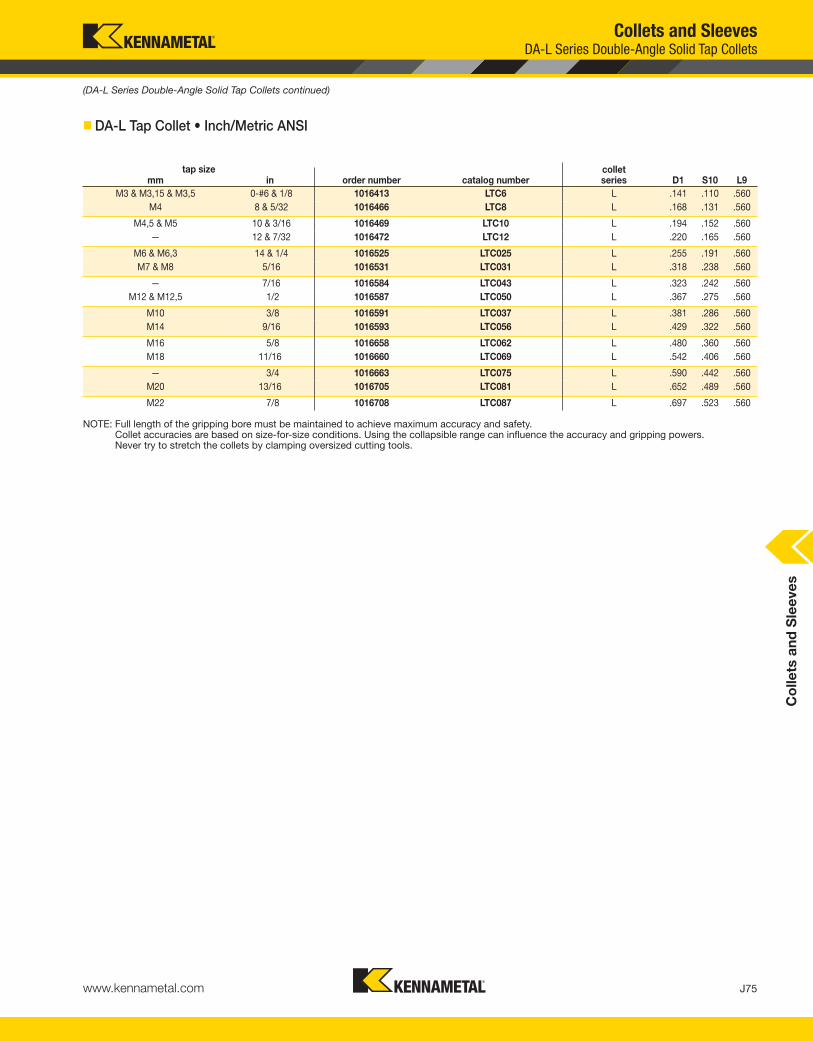
Co
lle
ts a
nd
Sle
eve
s
J75www.kennametal.com
tap sizemm in order number catalog number
collet series D1 S10 L9
M3 & M3,15 & M3,5 0-#6 & 1/8 1016413 LTC6 L .141 .110 .560
M4 8 & 5/32 1016466 LTC8 L .168 .131 .560
M4,5 & M5 10 & 3/16 1016469 LTC10 L .194 .152 .560
— 12 & 7/32 1016472 LTC12 L .220 .165 .560
M6 & M6,3 14 & 1/4 1016525 LTC025 L .255 .191 .560
M7 & M8 5/16 1016531 LTC031 L .318 .238 .560
— 7/16 1016584 LTC043 L .323 .242 .560
M12 & M12,5 1/2 1016587 LTC050 L .367 .275 .560
M10 3/8 1016591 LTC037 L .381 .286 .560
M14 9/16 1016593 LTC056 L .429 .322 .560
M16 5/8 1016658 LTC062 L .480 .360 .560
M18 11/16 1016660 LTC069 L .542 .406 .560
— 3/4 1016663 LTC075 L .590 .442 .560
M20 13/16 1016705 LTC081 L .652 .489 .560
M22 7/8 1016708 LTC087 L .697 .523 .560
� DA-L Tap Collet • Inch/Metric ANSI
NOTE: Full length of the gripping bore must be maintained to achieve maximum accuracy and safety.Collet accuracies are based on size-for-size conditions. Using the collapsible range can influence the accuracy and gripping powers.Never try to stretch the collets by clamping oversized cutting tools.
(DA-L Series Double-Angle Solid Tap Collets continued)
Collets and SleevesDA-L Series Double-Angle Solid Tap Collets
KEN_TOOLINGSYSTEMS11_J074_J075.qxp:WIDIA 11:38 AM Page J75

J76 www.kennametal.com
RC Rapid Quick-Change Tap Adapters • Tapping
Primary Application
ERICKSON RC Rapid Quick-Change Tap Adapters are convenient for hand changes with taps within seconds. No wrenches or locknuts are required. For this positive drive tap adapter, simply hold the tap in place with internal locking balls and drive on the tap square.
Features and Benefits
• Compact Rapid Change by hand design.
• Solid positive drive.
• Coolant through the tap design.
KEN_TOOLINGSYSTEMS11_J076_J077.qxp:WIDIA 11:38 AM Page J76

J77www.kennametal.com
Collets and SleevesRC-Style Solid Tap Adapters Catalog Numbering System
• Rapid-change style.
• Solid-positive drive.
• Coolant capability by using cutting toolwith coolant feature.
• For taps with DIN, ISO, and ANSI specifications.
025
TA = Tap Adapter M =Sleeve bore sizebuilt to metricvalues
IN =Sleeve bore sizebuilt to inchvalues
metric (xx.x)
025 = 2,5mm
110 = 11mm
245 = 24,5mm
inch (x.xxx)
0125 = 1/8"
0500 = 1/2"
RCT1A025021M010
RC1 = RC1
RC2 = RC2
RC3 = RC3
metric (xx.x)
010 = 1mm
160 = 16mm
245 = 24,5mm
inch (x.xxx)
0125 = 1/8"
0500 = 1/2"
1000 = 1"
Collet Bore Size
TACollet Style
RC1System
Size
MIdentification
Value
metric (xx.x)
010 = 1mm
160 = 16mm
245 = 24,5mm
inch (x.xxx)
0125 = 1/8"
0500 = 1/2"
1000 = 1"
010Tap Size
021Collet Drive
Size
KEN_TOOLINGSYSTEMS11_J076_J077.qxp:WIDIA 11:38 AM Page J77

J78 www.kennametal.com
Qu
ick
-Ch
an
ge
Ta
p A
da
pte
rs
tap sizeDIN
RC1D = 19mmD2 = 30mmL = 28mmL1 = 7mmL9 = 17mm
RC2D = 31mmD2 = 48mmL = 46mmL1 = 11mmL9 = 30mm
RC3D = 48mm
D2 = 70mmL = 70mm
L1 = 14mmL9 = 44mm D1 S10
M1 & M1.8 & M3 & M3.5 RC1TA025021M010 — — 2,5 2,1
M2.5 & M4 RC1TA028021M020 — — 2,8 2,1
M3 & M5 RC1TA035027M030 — — 3,5 2,7
M3.5 RC1TA040030M035 — — 4,0 3,0
M4 & M6 RC1TA045034M040 — — 4,5 3,4
M4 — RC2TA045034M040 — 4,5 3,4
M5 & M6 & M7 & M8 RC1TA060049M050 RC2TA060049M050 — 6,0 4,9
M10 RC1TA070055M100 RC2TA070055M100 — 7,0 5,5
M8 RC1TA080062M080 RC2TA080062M080 — 8,0 6,2
M12 RC1TA090070M120 RC2TA090070M120 — 9,0 7,0
M10 RC1TA100080M100 RC2TA100080M100 — 10,0 8,0
M14 RC1TA110090M140 RC2TA110090M140 RC3TA110090M140 11,0 9,0
M16 — — RC3TA120090M160 12,0 9,0
M16 — RC2TA120090M160 — 12,9 9,0
M18 — RC2TA140110M180 RC3TA140110M180 14,0 11,0
M20 — RC2TA160120M200 RC3TA160120M200 16,0 12,0
M22 & M24 — RC2TA180145M220 — 18,0 4,5
— — — RC3TA180140M240 18,0 14,0
M22 & M24 — — RC3TA180145M240 18,0 14,5
M27 — — RC3TA200160M300 20,0 16,0
M30 — — RC3TA220180M300 22,0 18,0
M33 — — RC3TA250200M360 25,0 20,0
M36 — — RC3TA280220M360 28,0 22,0
Quick-Change Tap AdaptersRC-Style Solid Tap Adapters
• Rapid Change style.
• Solid-positive drive.
• Coolant capability by using cutting tool with coolant feature.
• For taps with DIN, ISO, and ANSI specifications.
� RC Solid Tap Adapter • Metric DIN
(continued)
KEN_TOOLINGSYSTEMS11_J078_J079.qxp:WIDIA 11:39 AM Page J78

Qu
ick
-Ch
an
ge
Ta
p A
da
pte
rs
J79www.kennametal.com
tap size
RC1D = 19mmD2 = 30mmL = 28mmL1 = 7mm
L9 = 17mm
RC2D = 31mmD2 = 48mmL = 46mmL1 = 11mmL9 = 30mm
RC3D = 48mm
D2 = 70mmL = 70mmL1 = 14mmL9 = 44mm D1 S10
M3 RC1TA023018M030 — — 2,24 1,80
M2.2 & M2.5 RC1TA028023M025 — — 2,80 2,24
M3 & M4 RC1TA032025M030 — — 3,15 2,50
M3.5 & M4.5 RC1TA036028M035 — — 3,55 2,80
M4 & M5 RC1TA040032M040 — — 4,00 3,15
M4.5 & M6 RC1TA045036M060 RC2TA045036M060 — 4,50 3,55
M5 RC1TA050040M050 RC2TA050040M050 — 5,00 4,00
— RC1TA056045M000 — — 5,60 4,50
M6 & M8 RC1TA063050M060 RC2TA063050M060 — 6,30 5,00
M7 RC1TA071056M070 RC2TA071056M070 — 7,10 5,60
M8 & M10 & M11 RC1TA080063M080 RC2TA080063M080 — 8,00 6,30
M9 & M12 RC1TA090071M090 — — 9,00 7,10
M9 & M12 — RC2TA090071M090 — 9,00 7,10
M14 RC1TA112090M140 RC2TA112090M140 RC3TA112090M140 11,20 9,00
M16 — RC2TA125100M160 — 12,50 10,00
M18 & M20 — RC2TA140112M180 — 14,00 11,20
M22 — RC2TA160125M220 RC3TA160125M220 16,00 12,50
M24 — RC2TA180140M240 — 18,00 14,00
M33 — — RC3TA224180M330 22,40 18,00
� RC Solid Tap Adapter • Metric ISO
(RC-Style Solid Tap Adapters continued)
(continued)
Quick-Change Tap AdaptersRC-Style Solid Tap Adapters
KEN_TOOLINGSYSTEMS11_J078_J079.qxp:WIDIA 11:39 AM Page J79
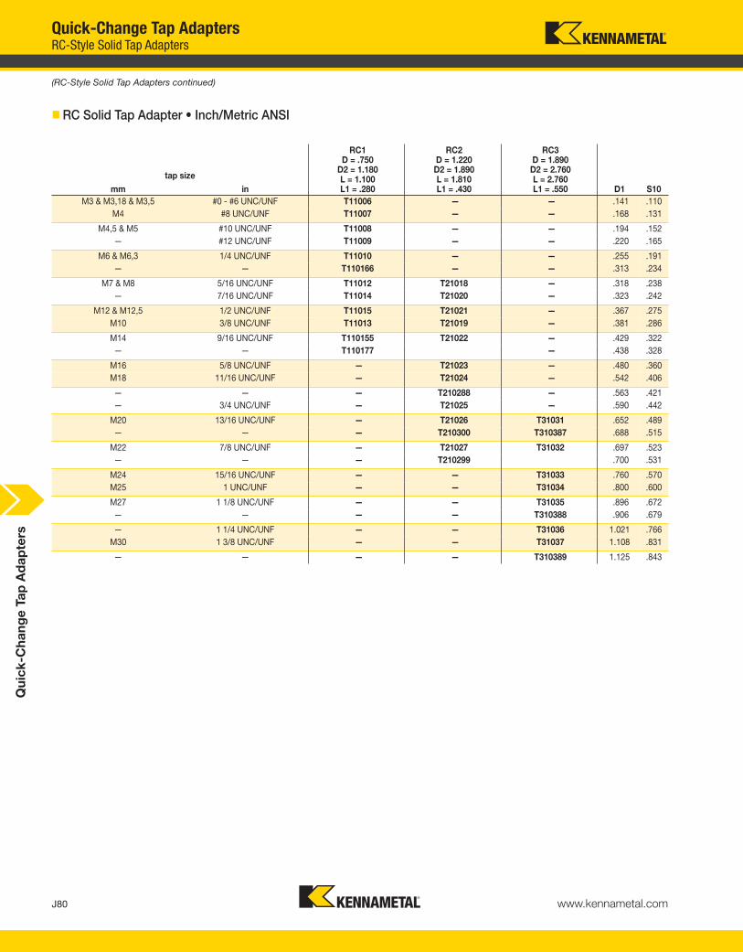
J80 www.kennametal.com
Qu
ick
-Ch
an
ge
Ta
p A
da
pte
rs
tap size
mm in
RC1D = .750
D2 = 1.180L = 1.100L1 = .280
RC2D = 1.220
D2 = 1.890L = 1.810L1 = .430
RC3D = 1.890D2 = 2.760L = 2.760L1 = .550 D1 S10
M3 & M3,18 & M3,5 #0 - #6 UNC/UNF T11006 — — .141 .110
M4 #8 UNC/UNF T11007 — — .168 .131
M4,5 & M5 #10 UNC/UNF T11008 — — .194 .152
— #12 UNC/UNF T11009 — — .220 .165
M6 & M6,3 1/4 UNC/UNF T11010 — — .255 .191
— — T110166 — — .313 .234
M7 & M8 5/16 UNC/UNF T11012 T21018 — .318 .238
— 7/16 UNC/UNF T11014 T21020 — .323 .242
M12 & M12,5 1/2 UNC/UNF T11015 T21021 — .367 .275
M10 3/8 UNC/UNF T11013 T21019 — .381 .286
M14 9/16 UNC/UNF T110155 T21022 — .429 .322
— — T110177 — .438 .328
M16 5/8 UNC/UNF — T21023 — .480 .360
M18 11/16 UNC/UNF — T21024 — .542 .406
— — — T210288 — .563 .421
— 3/4 UNC/UNF — T21025 — .590 .442
M20 13/16 UNC/UNF — T21026 T31031 .652 .489
— — — T210300 T310387 .688 .515
M22 7/8 UNC/UNF — T21027 T31032 .697 .523
— — — T210299 .700 .531
M24 15/16 UNC/UNF — — T31033 .760 .570
M25 1 UNC/UNF — — T31034 .800 .600
M27 1 1/8 UNC/UNF — — T31035 .896 .672
— — — — T310388 .906 .679
— 1 1/4 UNC/UNF — — T31036 1.021 .766
M30 1 3/8 UNC/UNF — — T31037 1.108 .831
— — — — T310389 1.125 .843
� RC Solid Tap Adapter • Inch/Metric ANSI
(RC-Style Solid Tap Adapters continued)
Quick-Change Tap AdaptersRC-Style Solid Tap Adapters
KEN_TOOLINGSYSTEMS11_J080_J081.qxp:WIDIA 11:39 AM Page J80

Qu
ick
-Ch
an
ge
Ta
p A
da
pte
rs
J81www.kennametal.com
catalog number series quantitydimensional
range
T1SET RC1 10 #0 - 9/16
T2SET RC2 10 5/16 - 7/8
Quick-Change Tap Adapters RC-Style Solid Tap Adapter Sets
• An economical way to purchase a set of RC tap adapters.
• Rapid Change style.
• Solid-positive drive.
• Coolant capability by using cutting tool withcoolant feature.
� RC Solid Tap Adapter Set • Inch
KEN_TOOLINGSYSTEMS11_J080_J081.qxp:WIDIA 11:39 AM Page J81

KEN_TOOLINGSYSTEMS11_L000_L001.qxp:WIDIA 11:41 AM Page L2

Shrink Fit Unit Offering . . . . . . . . . . . . . . . . . . . . . . . . . . . . . . . . . . . . . . . . . . . . . . . . . . . . . . . . . . . .L2Induction Shrink Fit Unit TTISG3400EU . . . . . . . . . . . . . . . . . . . . . . . . . . . . . . . . . . . . . . . . . . . .L4–L7Induction Shrink Fit Unit TTISG3400NA . . . . . . . . . . . . . . . . . . . . . . . . . . . . . . . . . . . . . . . . . . . .L4–L7Induction Shrink Fit Unit TTISG3400CCEU . . . . . . . . . . . . . . . . . . . . . . . . . . . . . . . . . . . . . . . .L8–L11Induction Shrink Fit Unit TTISG3400CCNA . . . . . . . . . . . . . . . . . . . . . . . . . . . . . . . . . . . . . . . .L8–L11Shrink Fit Axial Adjustment Gages . . . . . . . . . . . . . . . . . . . . . . . . . . . . . . . . . . . . . . . . . . . . . .L12–L13Balance Screw Sets . . . . . . . . . . . . . . . . . . . . . . . . . . . . . . . . . . . . . . . . . . . . . . . . . . . . . . . . . . . . . .L14HC Hydraulic Chuck Test Pins . . . . . . . . . . . . . . . . . . . . . . . . . . . . . . . . . . . . . . . . . . . . . . . . . . . . .L14HC Hydraulic Chuck Cleaning Brushes . . . . . . . . . . . . . . . . . . . . . . . . . . . . . . . . . . . . . . . . . . . . . .L15Collet Extractors TG . . . . . . . . . . . . . . . . . . . . . . . . . . . . . . . . . . . . . . . . . . . . . . . . . . . . . . . . . . . . . .L15TG Round Flush-Face Locknuts . . . . . . . . . . . . . . . . . . . . . . . . . . . . . . . . . . . . . . . . . . . . . . . . . . . .L16TG Balanceable Round Locknuts . . . . . . . . . . . . . . . . . . . . . . . . . . . . . . . . . . . . . . . . . . . . . . . . . . .L16Coolant Disk Assemblies . . . . . . . . . . . . . . . . . . . . . . . . . . . . . . . . . . . . . . . . . . . . . . . . . . . . . . . . . .L17TG Standard Round and Hex Locknuts . . . . . . . . . . . . . . . . . . . . . . . . . . . . . . . . . . . . . . . . . . . . . .L18ER Standard Short and Slim Locknuts . . . . . . . . . . . . . . . . . . . . . . . . . . . . . . . . . . . . . . . . . . . . . . .L19ER Slim Coolant and Hex Locknuts . . . . . . . . . . . . . . . . . . . . . . . . . . . . . . . . . . . . . . . . . . . . . . . . .L20ER Coolant Hex and Standard Round Locknuts . . . . . . . . . . . . . . . . . . . . . . . . . . . . . . . . . . . . . . .L21ER Coolant Round Locknuts . . . . . . . . . . . . . . . . . . . . . . . . . . . . . . . . . . . . . . . . . . . . . . . . . . . . . . .L22Coolant Locknut Sealing Disks and Disk Sets . . . . . . . . . . . . . . . . . . . . . . . . . . . . . . . . . . . .L23–L29
ER16 . . . . . . . . . . . . . . . . . . . . . . . . . . . . . . . . . . . . . . . . . . . . . . . . . . . . . . . . . . . . . . . . . . . .L23ER20 . . . . . . . . . . . . . . . . . . . . . . . . . . . . . . . . . . . . . . . . . . . . . . . . . . . . . . . . . . . . . . . . . . . .L24ER25 . . . . . . . . . . . . . . . . . . . . . . . . . . . . . . . . . . . . . . . . . . . . . . . . . . . . . . . . . . . . . . . . . . . .L25ER32 . . . . . . . . . . . . . . . . . . . . . . . . . . . . . . . . . . . . . . . . . . . . . . . . . . . . . . . . . . . . . . . .L26–L27ER40 . . . . . . . . . . . . . . . . . . . . . . . . . . . . . . . . . . . . . . . . . . . . . . . . . . . . . . . . . . . . . . . .L28–L29
DA 01 Double Angle Locknuts . . . . . . . . . . . . . . . . . . . . . . . . . . . . . . . . . . . . . . . . . . . . . . . . . . . . .L30DA 04 Double Angle Locknuts . . . . . . . . . . . . . . . . . . . . . . . . . . . . . . . . . . . . . . . . . . . . . . . . . . . . .L31DA 08 Double Angle Locknuts . . . . . . . . . . . . . . . . . . . . . . . . . . . . . . . . . . . . . . . . . . . . . . . . . . . . .L31Stop Screws . . . . . . . . . . . . . . . . . . . . . . . . . . . . . . . . . . . . . . . . . . . . . . . . . . . . . . . . . . . . . . . . . . . .L32Coolant and Blank Caps . . . . . . . . . . . . . . . . . . . . . . . . . . . . . . . . . . . . . . . . . . . . . . . . . . . . . . . . . .L34Extended Caps . . . . . . . . . . . . . . . . . . . . . . . . . . . . . . . . . . . . . . . . . . . . . . . . . . . . . . . . . . . . . . . . . .L35Shell Mill Adapter Lock Screws . . . . . . . . . . . . . . . . . . . . . . . . . . . . . . . . . . . . . . . . . . . . . . . .L36–L37Shell Mill Coolant Lock Screws . . . . . . . . . . . . . . . . . . . . . . . . . . . . . . . . . . . . . . . . . . . . . . . . . . . .L38Tightening Fixtures . . . . . . . . . . . . . . . . . . . . . . . . . . . . . . . . . . . . . . . . . . . . . . . . . . . . . . . . . . .L38–L41
KM Vise Mounts . . . . . . . . . . . . . . . . . . . . . . . . . . . . . . . . . . . . . . . . . . . . . . . . . . . . . . . . . . .L38KM4X and HSK Vise Mounts . . . . . . . . . . . . . . . . . . . . . . . . . . . . . . . . . . . . . . . . . . . . . . . . . .L39HSK Universal Mounts and Sleeves . . . . . . . . . . . . . . . . . . . . . . . . . . . . . . . . . . . . . . . . . . . . .L407/24 Steep Taper Vise and Universal Mounts . . . . . . . . . . . . . . . . . . . . . . . . . . . . . . . . . . . . .L41
P-KM and HSK Spindle Plugs . . . . . . . . . . . . . . . . . . . . . . . . . . . . . . . . . . . . . . . . . . . . . . . . . . . . . .L42KM, HSK, and 7/24 Steep Taper Spindle Wipers . . . . . . . . . . . . . . . . . . . . . . . . . . . . . . . . . . . . . . .L43HSK Coolant Supply Units and Wrenches . . . . . . . . . . . . . . . . . . . . . . . . . . . . . . . . . . . . . . . . . . . .L44Retention Knobs . . . . . . . . . . . . . . . . . . . . . . . . . . . . . . . . . . . . . . . . . . . . . . . . . . . . . . . . . . . . .L45–L50Socket Wrenches . . . . . . . . . . . . . . . . . . . . . . . . . . . . . . . . . . . . . . . . . . . . . . . . . . . . . . . . . . . . . . . .L51KM Manual Torque Wrenches . . . . . . . . . . . . . . . . . . . . . . . . . . . . . . . . . . . . . . . . . . . . . . . . . . . . . .L52KM-LOC II and KM-LOC Wrenches . . . . . . . . . . . . . . . . . . . . . . . . . . . . . . . . . . . . . . . . . . . . . . . . .L53T-Handle Hex Wrench Sets . . . . . . . . . . . . . . . . . . . . . . . . . . . . . . . . . . . . . . . . . . . . . . . . . . . . . . . .L54Universal Bit Drivers . . . . . . . . . . . . . . . . . . . . . . . . . . . . . . . . . . . . . . . . . . . . . . . . . . . . . . . . . . . . . .L55Driver Bits . . . . . . . . . . . . . . . . . . . . . . . . . . . . . . . . . . . . . . . . . . . . . . . . . . . . . . . . . . . . . . . . . . . . . .L55Open-Ended Wrenches . . . . . . . . . . . . . . . . . . . . . . . . . . . . . . . . . . . . . . . . . . . . . . . . . . . . . . . . . . .L56Pin Spanner and Hook Spanner Wrenches . . . . . . . . . . . . . . . . . . . . . . . . . . . . . . . . . . . . . . . . . . .L57Rapid and Rapid Plus Wrenches . . . . . . . . . . . . . . . . . . . . . . . . . . . . . . . . . . . . . . . . . . . . . . . . . . . .L58
Accessories
L1www.kennametal.com
KEN_TOOLINGSYSTEMS11_L000_L001.qxp:WIDIA 1:23 PM Page L3

Ac
ce
sso
rie
s
L2 www.kennametal.com
AccessoriesShrink Fit Unit Offering
EMEA, Asia, South America TTISG3400EU TTISG3400CCEU
North America TTISG3400NA TTISG3400CCNA
generator power 10 kW 10 kW
compressed air supply required 4 bar (58 psi) 4 bar (58 psi)input
supply power needed (3 phase) 3 x 400V/16A (EU)3 x 480V/16A (NA)
3 x 400V/16A (EU)3 x 480V/16A (NA)
cooling process water water
number of cooling stations 1 1
HSS shank diameters range/capacity 6–32 (50mm)(1/4–1-1/4"[2"])
6–32 (50mm)(1/4–1-1/4"[2"])
capability
carbide shank diameters range/capacity 3–32 (50mm)(1/8–1-1/4"[2"])
3–32 (50mm)(1/8–1-1/4"[2"])
process controlled semi automated fully automated
output process time 45 sec 45 sec
cost high highest
best top machine
** Unit needs transformer.
To learn more, scan here.
For instructions on how to scan, please see page xxxiii.
KEN_TOOLINGSYSTEMS11_L002_L003.qxp:WIDIA 11:41 AM Page L2

Difficult-to-Cut Materials Are
No Match for Kennametal’s
High Torque Shrink Fit System!
• HT line is ideal for heavy roughing operations that require higher
clamping torque levels (30–50% higher than the GP line).
• Increase productivity and reduce costs with a shrinking and
cooling process that takes 30 seconds or less!
• Precision engineered system ensures precise concentricity,
greater balancing quality, optimized bore sizes, and superior
metal removal rates.
• Increased accuracies when machining difficult to cut materials
common to the aerospace industry.
Two lines available to address all your High Torque (HT)
and General Purpose (GP) requirements.
Visit www.kennametal.com or contact your local Authorized Kennametal Distributor.
www.kennametal.com
®
KEN_TOOLINGSYSTEMS11_L002_L003.qxp:WIDIA 11:41 AM Page L3

5275128 TTISG3400EU induction shrink unit 400V/16A (CE and FC approved) for Europe/ROW
5275038 TTISG3400NA induction shrink unit 480V/16A (UL and CSA approved) for North America
L4 www.kennametal.com
AccessoriesInduction Shrink Fit Unit TTISG3400EU and TTISG3400NA
Induction Shrink Fit Unit TTISG3400EU and TTISG3400NA
The TTISG3400EU and TTISG3400NA is a top of the line unit that Kennametal offers withmanual processes and integral, enclosed water-cooling system. Built for Europe/ROW andthe North American market, fully CE and FC approved for Europe/ROW and fully UL® andCSA approved for North America with direct 400V, 16A for Europe/ROW or with direct480V, 16A for North America.3-phase electrical supply capabillity - no transformer needed.
• One permanent induction coil Ø 6–32mm (1/8–1-1/4").
• Four heating coil stop plates coveringrange of Ø 3–32mm (1/8–1-1/4").
• One disk holding clip.
• One heating coil stop (optional).
• Operation manual.
Essential accessories:
• Electrical transformer, if480V/16A 3-phase power notavailable for North America.
• Toolholder setting pot (V-flange, HSK, KM™).
• Liquid cooling; no cooling pots required.
� Shrink Fit Unit Complete
order number catalog number description
(continued)
Ac
ce
sso
rie
s
• 10 kW high-frequency generator — maximum 5 seconds heat cycle.
• 3 x 400V/16A Europe/ROW or 480/16A North America electrical supply needed.
• No air pressure supply needed.
• 560mm (22") D, 800mm (31.5") W, 950mm (37.5") H.
• Shrinking capacity carbide Ø 3–32mm (1/8–1-1/4") with supplied coil.
• Shrinking capacity HSS Ø 6–32mm (1/4–1-1/4") with supplied coil.
• Maximum toolholder gage length for cooling 160mm (6.3") for HSK63 toolholder.
• Maximum toolholder length for heating 400mm (15.75") for HSK63 toolholder.
• Shrink fit holder till outside geometry 65mm with extra Inver coil.
• Long life expectancy of toolholders while using pre-programmed parameters.
• Manual over-ride of pre-programmed parameters, time and power, to allow shrinking of special toolholder designs.
• Integrated coolant sprayer with coolant sleeve for consistent cooling down of the adapterwithin 25 seconds. (Complete toolchange process 30 seconds).
• Manual retreat of the toolholder after the cooling and cleaning process is finished.
• No drying action – no compressed air.
KEN_TOOLINGSYSTEMS11_L004_L005.qxp:WIDIA 11:41 AM Page L4

L5www.kennametal.com
� Toolholder Setting Pots (essential accessories)
• These pots are essential to locate toolholder in Shrink Fit Units.
order number catalog number description
3387728 TTISG3200LCPCCV30 30V flange adapter (BT, CV, DV, etc.)
3387729 TTISG3200LCPCCV40 40V flange adapter (BT, CV, DV, etc.)
3387730 TTISG3200LCPCCV50 50V flange adapter (BT, CV, DV, etc.)
3853186 TTISG3200LCPCCKM50 KM50™ flange adapters
3853187 TTISG3200LCPCCKM63 KM63™ flange adapters
3853188 TTISG3200LCPCCKM80 KM80™ flange adapters
3387731 TTISG3200LCPCCHSK32 32 HSK flange adapters
3387732 TTISG3200LCPCCHSK40 40 HSK flange adapters
3387763 TTISG3200LCPCCHSK50 50 HSK flange adapters
3387764 TTISG3200LCPCCHSK63 63 HSK flange adapters
3387765 TTISG3200LCPCCHSK80 80 HSK flange adapters
3387766 TTISG3200LCPCCHSK100 100 HSK flange adapters
NOTE: Retention knobs do not need to be removed on the V-flange design pots.
� Shrink Fit • Coil Stop (not included, optional accessory)
• Used on column to find edge at the front of extra slim/special toolholdersfor the coil positioning stop.
order number catalog number description
1779396 TTCS coil stop block
� Shrink Fit • Heating Coil (TTHC0332M included in TTISG3400CCEU and TTISG3400CCNA unit purchase)
• Easy, quick connection from supplied coil to larger capacity coil.
(Induction Shrink Fit Unit TTISG3400EU and TTISG3400NA continued)
AccessoriesInduction Shrink Fit Unit TTISG3400EU and TTISG3400NA
order number catalog number description
2641533 TTHC0332M induction coil Ø 3–32mm (1/8–1-1/4")
Ac
ce
sso
rie
s
KEN_TOOLINGSYSTEMS11_L004_L005.qxp:WIDIA 11:42 AM Page L5

order number catalog number description
3648695 TT3200HCSSP0306M coil stop plates Ø 3,0 to 5,9mm (.125" – .232")
3648696 TT3200HCSSP0612M coil stop plates Ø 6,0 to 12,0mm (.233" – .472")
3648697 TT3200HCSSP1220M coil stop plates Ø12,1 to 22,0mm (.473" – .866")
3648698 TT3200HCSSP2032M coil stop plates Ø 22,1 to 32,0mm (.867" – 1.260")
� Shrink Fit • Heating Coil Split Stop Plates (not included — optional accessory)
3003874 TTHCSP0306M coil stop plates Ø 3,0 to 5,9mm (.125" – .232")
3003875 TTHCSP0612M coil stop plates Ø 6,0 to 12,0mm (.233" – .472")
order number catalog number description
2614114 TTHCSP1220M coil stop plates Ø12,1 to 22,0mm (.473" – .866")
2613902 TTHCSP2032M coil stop plates Ø 22,1 to 32,0mm (.867" – 1.260”)
L6 www.kennametal.com
AccessoriesInduction Shrink Fit Unit TTISG3400EU and TTISG3400NA
� Shrink Fit • Heating Coil Stop Plates (included with TTISG3400EU and TTISG3400NA)
• Shields to protect cutting tool from heat soakand used as an automated stop for the coil.
� Heating Coil Holding Clip (included in TTISG3400EU and TTISG3400NA purchase)
• Clip holds stop plates in position within the heating coil.
• Split shields can be used for cutting tools withlarger cutting diameters than theholding/shrinking diameter.
• Shields to protect cutting tool from heat soak.
• Shields are designed for 400/480V version — will work in 208V version with manual alignment.
(continued)
Ac
ce
sso
rie
s
order number catalog number description
3003876 TTHCHC0332M holding clip
KEN_TOOLINGSYSTEMS11_L006_L007.qxp:WIDIA 11:42 AM Page L6

order number catalog number description
1850281 TTCCTRAY 3200 CC accessory tray
order number catalog number description
3648699 TT3200CCTRAY 3200 CC accessory tray
L7www.kennametal.com
� Shrink Fit • Accessory Tray (not included — optional accessory)
• Safe holding of stop plates, cutting tools —will have to be placed on a bench top.
� Shrink Fit • Accessory Cutting Tool Tray (not included — optional accessory)
• Safe holding of cutting tools.
(Induction Shrink Fit Unit TTISG3400EU and TTISG3400NA continued)
AccessoriesInduction Shrink Fit Unit TTISG3400EU and TTISG3400NA
Ac
ce
sso
rie
s
KEN_TOOLINGSYSTEMS11_L006_L007.qxp:WIDIA 11:42 AM Page L7
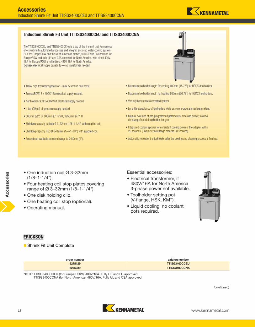
L8 www.kennametal.com
AccessoriesInduction Shrink Fit Unit TTISG3400CCEU and TTISG3400CCNA
Induction Shrink Fit Unit TTTISG3400CCEU and TTISG3400CCNA
The TTISG3400CCEU and TTISG3400CCNA is a top of the line unit that Kennametaloffers with fully automated processes and integral, enclosed water-cooling system. Built for Europe/ROW and the North American market, fully CE and FC approved forEurope/ROW and fully UL® and CSA approved for North America, with direct 400V, 16A for Europe/ROW or with direct 480V 16A for North America.3-phase electrical supply capability — no transformer needed.
• One induction coil Ø 3–32mm(1/8–1-1/4").
• Four heating coil stop plates coveringrange of Ø 3–32mm (1/8–1-1/4").
• One disk holding clip.
• One heating coil stop (optional).
• Operating manual.
Essential accessories:
• Electrical transformer, if480V/16A for North America3-phase power not available.
• Toolholder setting pot (V-flange, HSK, KM™).
• Liquid cooling: no coolantpots required.
� Shrink Fit Unit Complete
order number catalog number
5275129 TTISG3400CCEU
5275039 TTISG3400CCNA
NOTE: TTISG3400CCEU (for Europe/ROW): 400V/16A. Fully CE and FC approved.TTISG3400CCNA (for North America): 480V/16A. Fully UL and CSA approved.
(continued)
Ac
ce
sso
rie
s
• 10kW high frequency generator – max. 5 second heat cycle.
• Europe/ROW: 3 x 400V/16A electrical supply needed.
• North America: 3 x 480V/16A electrical supply needed.
• 4 bar (90 psi) air pressure supply needed.
• 560mm (22") D, 800mm (31.5") W, 1950mm (77") H.
• Shrinking capacity carbide Ø 3–32mm (1/8–1-1/4") with supplied coil.
• Shrinking capacity HSS Ø 6–32mm (1/4–1-1/4") with supplied coil.
• Second coil available to extend range to Ø 50mm (2").
• Maximum toolholder length for cooling 400mm (15.75") for HSK63 toolholders.
• Maximum toolholder length for heating 680mm (26,78") for HSK63 toolholders.
• Virtually hands free automated system.
• Long life expectancy of toolholders while using pre-programmed parameters.
• Manual over-ride of pre-programmed parameters, time and power, to allow shrinking of special toolholder designs.
• Integrated coolant sprayer for consistent cooling down of the adapter within 25 seconds. (Complete toolchange process 30 seconds).
• Automatic retreat of the toolholder after the cooling and cleaning process is finished.
KEN_TOOLINGSYSTEMS11_L008_L009.qxp:WIDIA 11:42 AM Page L8

order number catalog number description
3387728 TTISG3200LCPCCV30 30V flange adapter (BT, CV, DV, etc.)
3387729 TTISG3200LCPCCV40 40V flange adapter (BT, CV, DV, etc.)
3387730 TTISG3200LCPCCV50 50V flange adapter (BT, CV, DV, etc.)
3853186 TTISG3200LCPCCKM50 KM50™ flange adapters
3853187 TTISG3200LCPCCKM63 KM63™ flange adapters
3853188 TTISG3200LCPCCKM80 KM80™ flange adapters
3387731 TTISG3200LCPCCHSK32 32 HSK flange adapters
3387732 TTISG3200LCPCCHSK40 40 HSK flange adapters
3387763 TTISG3200LCPCCHSK50 50 HSK flange adapters
3387764 TTISG3200LCPCCHSK63 63 HSK flange adapters
3387765 TTISG3200LCPCCHSK80 80 HSK flange adapters
3387766 TTISG3200LCPCCHSK100 100 HSK flange adapters
order number catalog number description
2641533 TTHC0332M induction coil Ø 3–32mm (1/8–1-1/4")
2229225 TTHC3250M induction coil Ø 40–50mm (1-1/2–2")
� Shrink Fit • Coil Stop (not included, optional accessory)
L9www.kennametal.com
� Toolholder Setting Pots (essential accessories)
• These pots are essential to locate toolholder in Shrink Fit Units.
NOTE: Retention knobs do not need to be removed on the V-flange design pots.
order number catalog number description
1779396 TTCS coil stop block
� Shrink Fit • Heating Coil (TTHC0332M included in TTISG3400CCEU and TTISG3400CCNA unit purchase)
• Easy, quick connection from supplied coil to larger capacity coil.
AccessoriesInduction Shrink Fit Unit TTISG3400CCEU and TTISG3400CCNA
• Used on column to find edge at the front of extra slim/special toolholders for the coil positioning stop.
(Induction Shrink Fit Unit TTISG3400CCEU and TTISG3400CCNA continued)
(continued)
Ac
ce
sso
rie
s
KEN_TOOLINGSYSTEMS11_L008_L009.qxp:WIDIA 11:42 AM Page L9

order number catalog number description
3648695 TT3200HCSSP0306M coil stop plates Ø 3,0 to 5,9mm (.125" – .232")
3648696 TT3200HCSSP0612M coil stop plates Ø 6,0 to 12,0mm (.233" – .472")
3648697 TT3200HCSSP1220M coil stop plates Ø12,1 to 22,0mm (.473" – .866")
3648698 TT3200HCSSP2032M coil stop plates Ø 22,1 to 32,0mm (.867" – 1.260")
order number catalog number description
3003874 TTHCSP0306M coil stop plates Ø 3,0 to 5,9mm (.125" – .232")
3003875 TTHCSP0612M coil stop plates Ø 6,0 to 12,0mm (.233" – .472")
2614114 TTHCSP1220M coil stop plates Ø12,1 to 22,0mm (.473" – .866")
2613902 TTHCSP2032M coil stop plates Ø 22,1 to 32,0mm (.867" – 1.260")
L10 www.kennametal.com
AccessoriesInduction Shrink Fit Unit TTISG3400CCEU and TTISG3400CCNA
� Shrink Fit • Heating Coil Stop Plates (included with TTISG3400CCEU and TTISG3400CCNA)
• Shields to protect cutting tool from heat soak and used as an automated stop for the coil.
� Heating Coil Holding Clip (included in TTISG3400CCEU and TTISG3400CCNA purchase)
• Clip holds stop plates in position within the heating coil.
� Shrink Fit • Heating Coil Split Stop Plates (not included — optional accessory)
• Split shields can be used for cutting tools withlarger cutting diameters than theholding/shrinking diameter.
• Shields to protect cutting tool from heat soak.
• Shields are designed for 400/480V version —will work in 208V version with manual alignment.
(Induction Shrink Fit Unit TTISG3400CCEU and TTISG3400CCNA continued)
(continued)
order number catalog number description
3003876 TTHCHC0332M holding clip
Ac
ce
sso
rie
s
KEN_TOOLINGSYSTEMS11_L010_L011.qxp:WIDIA 11:42 AM Page L10

order number catalog number description
1850281 TTCCTRAY 3200 CC accessory tray
order number catalog number description
3648699 TT3200CCTRAY 3200 CC accessory tray
L11www.kennametal.com
� Shrink Fit • Accessory Tray (not included — optional accessory)
• Safe holding of stop plates, cutting tools —
will have to be placed on a bench top.
• Safe holding of cutting tools.
(Induction Shrink Fit Unit TTISG3400CCEU and TTISG3400CCNA continued)
� Shrink Fit • Accessory Cutting Tool Tray (not included — optional accessory)
AccessoriesInduction Shrink Fit Unit TTISG3400CCEU and TTISG3400CCNA
Ac
ce
sso
rie
s
KEN_TOOLINGSYSTEMS11_L010_L011.qxp:WIDIA 11:42 AM Page L11

order number catalog number D D1 D2 L L1 DRVS
2441761 TTAAG03M 3 3 20 50 40 3mm
2456185 TTAAG04M 4 4 20 52 40 4mm
2456186 TTAAG05M 5 5 20 55 40 3mm
1801298 TTAAG06M 6 6 25 110 80 2,5mm
1775603 TTAAG08M 8 8 25 112 80 3mm
1775604 TTAAG10M 10 10 30 117 80 4mm
1775605 TTAAG12M 12 12 30 117 80 4mm
3110267 TTAAG12MX1 12 12 30 117 80 5mm
1775606 TTAAG14M 14 14 30 117 80 4mm
3110268 TTAAG14MX1 14 14 30 117 80 5mm
5086814 TTAAG16MX1 16 16 30 120 80 5mm
1775608 TTAAG16M 16 16 30 120 80 6mm
5086815 TTAAG18MX1 18 18 30 120 80 5mm
1775609 TTAAG18M 18 16 30 120 80 6mm
5086816 TTAAG20MX1 20 20 40 120 80 5mm
1775610 TTAAG20M 20 20 40 120 80 8mm
5086817 TTAAG25MX1 25 25 40 124 80 5mm
1784105 TTAAG25M 25 25 40 124 80 8mm
5086818 TTAAG32MX1 32 32 40 124 80 5mm
1775611 TTAAG32M 32 32 40 124 80 8mm
L12 www.kennametal.com
Accessories
� TTAAG • Metric
®
Cutting tool length adjustment is performed using a special axial adjusting gage(B) before shrinking the cutting tool into the toolholder.
An axial adjustment gage is placed in the toolholder (A) along with the cuttingtool (C). Length difference of the setting gage (L1) is calculated into the required tool assembly length.
The whole assembly then can be placed into a length presetter for adjustment.
Rotating the gage moves the axial stop screw and presets the assembled tool to the required length. Remove the gage; the cutting tool can then be shrunkinto the toolholder.
In some cases, there are two different gage options for the D bore size. The only difference is the DRVS hex drive size to accommodate a recent DIN standard change.
(continued)
Shrink Fit Axial Adjustment Gages
Shrink Fit Axial Adjustment Gages
Ac
ce
sso
rie
s
KEN_TOOLINGSYSTEMS11_L012_L013.qxp:WIDIA 11:42 AM Page L12

L13www.kennametal.com
� TTAAG • Inch
order number catalog number D D1 D2 L L1 DRVS
1765666 TTAAG025 1/4 .250 .984 4.33 3.15 2,5mm
1765669 TTAAG031 5/16 .313 .984 4.41 3.15 3mm
1765670 TTAAG038 3/8 .375 1.181 4.61 3.15 4mm
1765671 TTAAG044 7/16 .438 1.181 4.41 3.15 4mm
3110269 TTAAG044X1 7/16 .438 1.181 4.41 3.15 5mm
1765702 TTAAG050 1/2 .500 1.181 4.61 3.15 4mm
3110270 TTAAG050X1 1/2 .500 1.181 4.61 3.15 5mm
1765703 TTAAG056 9/16 .563 1.181 4.61 3.15 4mm
3110271 TTAAG056X1 9/16 .563 1.181 4.61 3.15 5mm
1765704 TTAAG062 5/8 .625 1.181 4.72 3.15 6mm
1765705 TTAAG068 11/16 .688 1.181 4.72 3.15 6mm
1765707 TTAAG075 3/4 .750 1.575 4.72 3.15 8mm
1765708 TTAAG088 7/8 .875 1.575 4.72 3.15 8mm
1765709 TTAAG100 1 1.000 1.575 4.88 3.15 8mm
1765710 TTAAG125 1 1/4 1.250 1.850 4.88 3.15 8mm
AccessoriesShrink Fit Axial Adjustment Gages
(TTAAG continued)
Ac
ce
sso
rie
s
KEN_TOOLINGSYSTEMS11_L012_L013.qxp:WIDIA 11:42 AM Page L13

L14 www.kennametal.com
order number catalog number
3367391 HPMCBALSCREWSET
AccessoriesBalance Screw Sets • HC Hydraulic Chuck Test Pins
• Standard balance screw set is used on HPMCbearing milling chuck.
• Total number of screws in each set is 110.
• All are M6 screws.
• Eleven different lengths from 3,5–8mm.
• Eleven different weights, 10 of each, varying between 0,047–1,138 grams.
• Set comes complete in a divider box and screwdriver.
• For high-performance milling choices.
� Balance Screw Set
• It is important to periodically check the clamping function on a hydraulic chuck with a test pin for clamping clarity.
• The clamping grip can be checked quickly and easily by placingthe correct test pin in the chuck bore and the turning the clampscrew to the limit stop. The chuck is functioning correctly if thetesting pin cannot be moved by hand.
� HC Test Pin • Metric
order number catalog number D
1191037 280.200 6
1191039 280.202 10
1191040 280.203 12
1245409 280.204 14
1191041 280.205 16
1245410 280.206 18
1191042 280.207 20
1245411 280.208 25
1191043 280.209 32
� HC Test Pin • Inch
order number catalog number D
1247566 280.262 3/8
1247570 280.264 1/2
1247572 280.266 5/8
1247575 280.268 3/4
1247577 280.269 1
Ac
ce
sso
rie
s
KEN_TOOLINGSYSTEMS11_L014_L015.qxp:WIDIA 11:42 AM Page L14

L15www.kennametal.com
AccessoriesHC Hydraulic Chuck Cleaning Brushes • Collet Extractors TG
• Hydraulic chucks are maintenance-free and deliver a long service life. A non-abrasive cleaning brush is recommended to help maintain the performance and accuracy of the clamping bore of the hydraulic chuck and reducing sleeves.
D1
� Cleaning Brush
D1
order number catalog number mm in
1138729 192.950 6 1/4
1138736 192.951 8 5/16
1138744 192.952 10 3/8
1138752 192.953 12 1/2
1138759 192.954 14 9/16
1138766 192.955 16 5/8
1138914 192.956 18 11/16
1138853 192.957 20 3/4
1138922 192.958 25 1
1138930 192.959 32 1 1 /4
• Assists with collet extraction from locknut.
� TG • CE
order number catalog numbersystem
size
1106809 50TGCE TG50
1106812 75TGCE TG75
1106813 100TGCE TG100
1106814 150TGCE TG150
system size
Ac
ce
sso
rie
s
KEN_TOOLINGSYSTEMS11_L014_L015.qxp:WIDIA 11:42 AM Page L15

L16 www.kennametal.com
Accessories
� TG Locknut • Round Flush Face
NOTE: Locknut wrench must be ordered separately.WF = Open-ended wrench size.
D11 L LF WF
order number catalog number mm in mm in mm in mm in G3wrench
size Nm ft. lbs.
2980879 LNATGF050M 38 1.50 18,3 .72 10,6 .42 34 1.34 15/16-20 UNEF HSW34M 81 60
2980880 LNATGF075M 50 1.97 23,4 .92 13,0 .51 46 1.81 1 1/2-12 ACME HSW45M 150 110
2980881 LNATGF100M 60 2.36 30,2 1.19 16,4 .65 55 2.17 1 7/8-12 ACME HSW58M 203 150
• TG flush mount, coolant-capable locknuts, and coolant disks/caps can be used on allstandard TG collet chucks to seal standard TG collets.
• Face is completely flush.
• Includes the original ball bearing race design.
• External diameter is the same as existing global round TG locknut.
• Operated by a standard open-ended wrench or the original hook-style wrench.
• TG flush mount coolant capable locknuts and coolant disks/caps are interchangeable with existing designs.
• Utilizes standard TG collets.
Ac
ce
sso
rie
s
• Balanceable and interchangeable locknuts can be ordered separatelyas an option to the original standard locknut supplied on collet chucks.
order number catalog number mm in mm in mm in mm in mm in G3wrench
size Nm ft. lbs.balance ring set
1020465 HPVLNA050G 38,0 1.50 42,5 1.67 20,0 .79 10,05 .40 9,7 .38 15/16-20 UNEF HSW34M 81 60 SHVBR0325M
1091592 HPVLNA075G 50,0 1.97 56,5 2.22 25,0 .98 12,05 .47 14,4 .57 1 1/2-12 ACME HSW45M 150 110 SHVBR0445M
1020466 HPVLNA100G 60,0 2.36 66,5 2.62 33,0 1.30 12,05 .47 19,1 .75 1 7/8-12 ACME HSW58M 203 150 SHVBR0545M
� TG Locknut Round • Balanceable
Note: Collet must be loaded into locknut first. Before loading into the chuck body, insert the cutting tool, then tighten according to torque reccommendations. Collet chuck technical section, see pages M98–M99.Locknut wrench must be ordered separately.Balance rings are supplied with locknut and adjustment directions.
D11 D12 L L23 LF
TG Round Flush-Face Locknuts • TG Balanceable Round Locknuts
KEN_TOOLINGSYSTEMS11_L016_L017.qxp:WIDIA 11:42 AM Page L16

L17www.kennametal.com
• TG coolant disk cap assemblies are used inconjunction with the TG flush-style locknuts and collet chucks to seal standard TG collets.
• Utilizes the ER coolant disks.
• High-pressure coolant up to 150 bar (1,500 psi).
• Withstands most of today’s coolants.
• Seals against chip packing and machined contaminants.
� TG Nut • Coolant Disk Assembly
NOTE: Tighten the four assembly screws to the recommended tightening torque.Assembly screws to locknuts are supplied with the appropriate wrench.ER coolant disks must be ordered separately; see page L23.Collet must be loaded into locknut first. Before loading into the chuck body, insert the cutting tool, then tighten to torque recommendations.Collet chuck technical section, see page M98.Locknut wrench must be ordered separately.
Accessories
order number catalog number mm in mm in mm inlock
screwlocknut
referenceER coolant
disk reference Nm ft. lbs.
2980882 TG050CDA 21,0 .827 40 1.6 5,7 .22 MS311 LNATGF050M ER25 25 18
2980893 TG075CDA 27,0 1.063 50 2.0 5,7 .22 MS1488 LNATGF075M ER32 25 18
2980894 TG100CDA 33,5 1.319 60 2.4 5,7 .22 MS1488 LNATGF100M ER40 25 18
D1 D2 L
Coolant Disk Assemblies
Ac
ce
sso
rie
s
KEN_TOOLINGSYSTEMS11_L016_L017.qxp:WIDIA 11:42 AM Page L17

L18 www.kennametal.com
AccessoriesTG Standard Round Locknuts • Hex Locknuts
• Standard and replaceable locknuts are usually supplied as the standard option with the original collet chuck.
NOTE: Locknut wrench must be ordered separately.
NOTE: Locknut wrench must be ordered separately.WF = Open-ended wrench size.
order number catalog number mm in mm in mm in G3locknutwrench Nm ft. lbs.
1013486 LNA075M 50,0 1.97 25,0 .98 14,4 .57 1 1/2-12 ACME HSW45M 136 100
1013485 LNA100M 60,0 2.36 33,0 1.30 19,1 .75 1 7/8-12 ACME HSW58M 203 150
1013484 LNA150M 85,0 3.35 37,0 1.46 18,0 .71 2 5/8-12 ACME HSW80M 271 200
1020326 NPA150 88,3 3.48 34,9 1.38 18,6 .73 2 5/8-12 ACME PSW350 271 200
D11 L LF
D11 L LF
order number catalog number mm in mm in mm in G3locknutwrench WF Nm ft. lbs.
1020290 NPA050 30,2 1.19 21,4 .84 14,6 .58 15/16-20 2B OEW106 1 1/16 102 75
4134686 LN050M 34,0 1.34 19,0 .75 9,8 .38 15/16-20 UNEF OEW30M 30mm 136 100
1020289 NPA075 53,2 2.09 28,4 1.12 19,7 .78 1 1/2-12 ACME OEW188 1 7/8 136 100
1020331 NPA100 61,9 2.44 35,7 1.41 25,1 .99 1 7/8-12 ACME OEW225 2 1/4 203 150
� TG Locknut • Round
� TG Locknut • Hex
Ac
ce
sso
rie
s
KEN_TOOLINGSYSTEMS11_L018_L019.qxp:WIDIA 11:42 AM Page L18

� ER Locknut • Slim
L19www.kennametal.com
D11 L LF
order number catalog numbercolletseries mm in mm in mm in G3
locknutwrench
wrenchsize Nm ft. lbs.
2978768 LNECSER32M ER32 35,9 1.41 14,4 .57 8 .32 M40 x 1.5 OEW32M 32 136 100
2978769 LNECSER40M ER40 46,0 1.81 16,0 .63 8 .32 M50 x 1.5 OEW168 1 11/16 176 130
AccessoriesER Standard Short Locknuts • Slim Locknuts
• Standard and replaceable locknuts are supplied as the standard option with the original short-style collet chuck.
� ER Locknut • Short
NOTE: Locknut wrench must be ordered separately.
NOTE: Locknut wrench must be ordered separately.
D11 L LF
order number catalog numbercolletseries mm in mm in mm in G3
locknutwrench
counterbore collettorque (Nm)
straight collettorque (Nm)
counterbore collettorque
(in. lbs.)
straight collettorque
(in. lbs.)
1024642 LER08M ER08 12 .47 10,8 .43 6,1 .24 M10 X .75 ER08WEM 5 5 42 42
1024643 LER11M ER11 16 .63 12,0 .47 7,5 .30 M13 X .75 ER11WEM 12 16 106 142
1016342 LER16M ER16 22 .87 18,4 .72 11,5 .45 M19 X 1 ER16WEM 24 24 212 212
1799219 LER20M ER20 28 1.10 19,0 .75 11,5 .45 M24 X 1 ER20WEM 28 28 248 248
Ac
ce
sso
rie
s
KEN_TOOLINGSYSTEMS11_L018_L019.qxp:WIDIA 11:43 AM Page L19

L20 www.kennametal.com
D11 L LNC LF
order number catalog numbercolletseries mm in mm in mm in mm in G3
locknutwrench Nm in. lbs.
2255307 LABER16M ER16 22 .87 22 .87 4,5 .18 11,5 .45 M19 X 1 ER16WEM 24 212
2398953 LABER20M ER20 28 1.10 24 .94 5,0 .20 13,0 .51 M24 X 1 ER20WEM 28 248
AccessoriesER Slim Coolant Locknuts • Hex Locknuts
• Interchangeable with slim locknuts.
• Must be ordered separately.
• Used in conjunction with ER coolant-sealing disks for high-pressure coolant applications up to 150 bar (2,000 psi). Must be ordered separately; see page L23.
� ER Locknut • Slim Coolant
NOTE: Locknut wrench must be ordered separately.
G3
• Standard and replaceable locknuts are usuallysupplied as the standard option with the originalcollet chuck.
NOTE: Locknut wrench must be ordered separately.
order number catalog number
colletseries mm in mm in mm in G3
locknutwrench
wrench size Nm ft. lbs.
counterbore collettorque (Nm)
straight collettorque (Nm)
counterbore collettorque (ft. lbs.)
straight collettorque (ft. lbs.)
3062811 LNHSER16M ER16 28,0 1.10 17,5 .69 10,5 .41 M22 X 1.5 OEW25M 25mm 56 42 40 56 30 42
3062812 LNHSER20M ER20 34,0 1.34 19,0 .75 11,5 .45 M25 X 1.5 OEW30M 30mm 80 59 32 80 24 59
� ER Locknut • Hex
D11 L LF
Ac
ce
sso
rie
s
KEN_TOOLINGSYSTEMS11_L020_L021.qxp:WIDIA 11:43 AM Page L20

L21www.kennametal.com
AccessoriesER Coolant Hex Locknuts • Standard Round Locknuts
• Interchangeable with standard locknuts.
• Must be ordered separately.
• Used in conjunction with ER coolant-sealing disks for high-pressure coolant applications up to 150 bar (2,000 psi). Must be ordered separately; see page L23.
NOTE: Locknut wrench must be ordered separately.
order number catalog numbercolletseries mm in mm in mm in G3
locknutwrench Nm ft. lbs.
3063113 LNSER25M ER25 42 1.65 20 .79 12 .47 M32 X 1.5 ER25WM 104 77
3063114 LNSER32M ER32 50 1.97 23 .89 13 .51 M40 X 1.5 ER32WM 136 100
3063115 LNSER40M ER40 63 2.48 26 1.00 15 .59 M50 X 1.5 ER40WM 176 130
• Standard and replaceable locknuts are usually supplied as the standard option with the original collet chuck.
NOTE: Locknut wrench must be ordered separately.
D11 L LNC LF
order number catalog numbercolletseries mm in mm in mm in mm in G3
locknutwrench
wrenchsize
counterbore collettorque (Nm)
straight collettorque (Nm)
counterbore collettorque (ft. lbs.)
straight collettorque (ft. lbs.)
1854738 LNHABER16M ER16 28,0 1.10 22,5 .89 5,0 .20 15,5 .61 M22 X 1.5 OEW25M 25mm 40 56 30 42
1859410 LNHABER20M ER20 34,0 1.34 24,0 .94 5,0 .20 16,5 .65 M25 X 1.5 OEW30M 30mm 32 80 24 59
D11 L LF
� ER Locknut Hex • Coolant
� ER Locknut • Round
Ac
ce
sso
rie
s
KEN_TOOLINGSYSTEMS11_L020_L021.qxp:WIDIA 11:43 AM Page L21

L22 www.kennametal.com
order number catalog numbercolletseries mm in mm in mm in mm in G3
locknutwrench Nm ft. lbs.
1127154 LNABER25M ER25 42 1.65 25,0 .98 5 .20 17 .67 M32 X 1.5 ER25WM 104 77
1128857 LNABER32M ER32 50 1.97 27,5 1.08 5 .20 18 .71 M40 X 1.5 ER32WM 136 100
1125692 LNABER40M ER40 63 2.48 30,5 1.20 5 .20 20 .79 M50 X 1.5 ER40WM 176 130
AccessoriesER Coolant Round Locknuts
• Interchangeable with standard locknuts;must be ordered separately.
• Used in conjunction with ER coolant-sealing disks for high-pressure coolant applications up to 150 bar(2,000 psi). Must be ordered separately; see page L23.
� ER Locknut Round • Coolant
NOTE: Locknut wrench must be ordered separately.
D11 L LNC LF
Ac
ce
sso
rie
s
KEN_TOOLINGSYSTEMS11_L022_L023.qxp:WIDIA 11:43 AM Page L22

L23www.kennametal.com
order number catalog numbercolletseries
rangemetric
rangeinch
rangefraction
1128244 CDER16035M ER16 3,0–3,5 .1181–.1387 1/8
1122128 CDER16040M ER16 3,5–4,0 .1378–.1575 5/32
1125973 CDER16045M ER16 4,0–4,5 .1575–.1772 —
1125741 CDER16050M ER16 4,5–5,0 .1772–.1969 3/16
1260100 CDER16055M ER16 5,0–5,5 .1969–.2165 7/32
1130781 CDER16060M ER16 5,5–6,0 .2165–.2362 —
1260101 CDER16065M ER16 6,0–6,5 .2362 -.2559 1/4
1260102 CDER16070M ER16 6,5–7,0 .2559–.2756 —
1260103 CDER16075M ER16 7,0–7,5 .2756–.2953 9/32
1124948 CDER16080M ER16 7,5–8,0 .3150–.3347 5/16
1254499 CDER16085M ER16 8,0–8,5 .3150–.3347 —
1120977 CDER16090M ER16 8,5–9,0 .3347–.3543 11/32
1260104 CDER16095M ER16 9,0–9,5 .3543–.3740 3/8
1128201 CDER16100M ER16 9,5–10,0 .3740–.3937 —
AccessoriesER16 Coolant Locknut Sealing Disks • Disk Sets
• 0,5mm (.020") range of sealing per disk.
• High-pressure coolant up to 150 bar (2,000 psi).
• Accommodates both metric- and inch-sized cutting tool shanks.
• Standard-sized replaceable O-rings.
� ER16 Locknut Coolant Seal Disk
order number catalog numbercolletseries quantity
dimensionalrange
incrementaldivision
1148501 CDER16000M ER16 14 3,5mm–10mm .5mm
• An economical way to purchase a group of coolant disks.
� ER16 Locknut Coolant Seal Disk Set
NOTE: ER coolant disk sets come complete with wooden protective tray.
Ac
ce
sso
rie
s
KEN_TOOLINGSYSTEMS11_L022_L023.qxp:WIDIA 11:43 AM Page L23

L24 www.kennametal.com
(.63)Ø 16,0
order number catalog numbercolletseries
rangemetric
rangeinch
rangefraction
1882862 CDER20030M ER20 2,5–3,0 .0984–.1181 —
2046541 CDER20035M ER20 3,0–3,5 .1181–.1387 1/8
2046542 CDER20040M ER20 3,5–4,0 .1378–.1575 5/32
1785844 CDER20045M ER20 4,0–4,5 .1575–.1772 —
2046613 CDER20050M ER20 4,5–5,0 .1772–.1969 3/16
2046614 CDER20055M ER20 5,0–5,5 .1969–.2165 7/32
1600448 CDER20060M ER20 5,5–6,0 .2165–.2362 —
2046615 CDER20065M ER20 6,0–6,5 .2362 -.2559 1/4
1821042 CDER20070M ER20 6,5–7,0 .2559–.2756 —
2046616 CDER20075M ER20 7,0–7,5 .2756–.2953 9/32
1568338 CDER20080M ER20 7,5–8,0 .3150–.3347 5/16
2046617 CDER20085M ER20 8,0–8,5 .3150–.3347 —
1567466 CDER20090M ER20 8,5–9,0 .3347–.3543 11/32
2046618 CDER20095M ER20 9,0–9,5 .3543–.3740 3/8
1747032 CDER20100M ER20 9,5–10,0 .3740–.3937 —
2046619 CDER20105M ER20 10,0–10,5 .3937–.4134 13/32
1923780 CDER20110M ER20 10,5–11,0 .4314–.4330 —
2046620 CDER20115M ER20 11,0–11,5 .4330–.4528 7/16
1883015 CDER20120M ER20 11,5–12,0 .4528–.4724 15/32
2046621 CDER20125M ER20 12,0–12,5 .4724–.4921 —
2046622 CDER20130M ER20 12,5–13,0 .4921–.5118 1/2
AccessoriesER20 Coolant Locknut Sealing Disks • Disk Sets
• 0,5mm (.020") range of sealing per disk.
• High-pressure coolant up to 150 bar (2,000 psi).
• Accommodates both metric- and inch-sized cutting tool shanks.
• Standard-sized, replaceable O-rings.
� ER20 Locknut Coolant Seal Disk
order number catalog numbercolletseries quantity
dimensionalrange
incrementaldivision
1720848 CDER20000M ER20 20 3,5mm–13mm .5mm
• An economical way to purchase a group of coolant disks.
� ER20 Locknut Coolant Seal Disk Set
NOTE: ER coolant disk sets come complete with wooden protective tray.
Ac
ce
sso
rie
s
KEN_TOOLINGSYSTEMS11_L024_L025.qxp:WIDIA 11:43 AM Page L24

L25www.kennametal.com
order number catalog numbercolletseries
rangemetric
rangeinch
rangefraction
1820323 CDER25035M ER25 3,0 - 3,5 .1181 - .1387 1/8
1136043 CDER25040M ER25 3,5 - 4,0 .1378 - .1575 5/32
1260105 CDER25045M ER25 4,0 - 4,5 .1575 - .1772 —
1130194 CDER25050M ER25 4,5 - 5,0 .1772 - .1969 3/16
1260106 CDER25055M ER25 5,0 - 5,5 .1969 - .2165 7/32
1127146 CDER25060M ER25 5,5 - 6,0 .2165 - .2362 —
1260107 CDER25065M ER25 6,0 - 6,5 .2263 -.2559 1/4
1126670 CDER25070M ER25 6,5 - 7,0 .2559 - .2756 —
1260108 CDER25075M ER25 7,0 - 7,5 .2756 - .2953 9/32
1126607 CDER25085M ER25 8,0 - 8,5 .3150 - .3347 —
1126599 CDER25080M ER25 7,5 - 8,0 .3150 - .3347 —
1129478 CDER25090M ER25 8,5 - 9,0 .3347 - .3543 11/32
1260109 CDER25095M ER25 9,0 - 9,5 .3543 - .3740 3/8
1126613 CDER25100M ER25 9,5 - 10,0 .3740 - .3937 —
1124966 CDER25105M ER25 10,0 - 10,5 .3937 - .4134 13/32
1126677 CDER25110M ER25 10,5 - 11,0 .4134 - .4330 —
1260110 CDER25115M ER25 11,0 - 11,5 .4330 - .4528 7/16
1125474 CDER25120M ER25 11,5 - 12,0 .4528 - .4724 15/32
1260111 CDER25125M ER25 12,0 - 12,5 .4724 - .4921 —
1129141 CDER25130M ER25 12,5 - 13,0 .4921 - .5118 1/2
1260112 CDER25135M ER25 13,0 - 13,5 .5118 - .5315 17/32
1125481 CDER25140M ER25 13,5 - 14,0 .5315 - .5512 —
1260113 CDER25145M ER25 14,0 - 14,5 .5512 - .5709 9/16
1260114 CDER25150M ER25 14,5 - 15,0 .5709 - .5906 37/64
1260115 CDER25155M ER25 15,0 - 15,5 .5906 - .6102 19/32
1128486 CDER25160M ER25 15,5 - 16,0 .6102 - .6300 5/8
AccessoriesER25 Coolant Locknut Sealing Disks • Disk Sets
• 0,5mm (.020") range of sealing per disk.
• High-pressure coolant up to 150 bar (2,000 psi).
• Accommodates both metric- and inch-sized cutting tool shanks.
• Standard-sized, replaceable O-rings.
� ER25 Locknut Coolant Seal Disk
order number catalog numbercolletseries quantity
dimensionalrange
incrementaldivision
1254501 CDER25000M ER25 26 3,5mm–16mm .5mm
• An economical way to purchase a group of coolant disks.
� ER25 Locknut Coolant Seal Disk Set
NOTE: ER coolant disk sets come complete with wooden protective tray.
Ac
ce
sso
rie
s
KEN_TOOLINGSYSTEMS11_L024_L025.qxp:WIDIA 11:43 AM Page L25

L26 www.kennametal.com
order number catalog numbercolletseries
rangemetric
rangeinch
rangefraction
1120969 CDER32035M ER32 3,0–3,5 .1181–.1387 1/8
1125347 CDER32040M ER32 3,5–4,0 .1378–.1575 5/32
1260116 CDER32045M ER32 4,0–4,5 .1575–.1772 —
1148555 CDER32050M ER32 4,5–5,0 .1772–.1969 3/16
1260117 CDER32055M ER32 5,0–5,5 .1969–.2165 7/32
1121104 CDER32060M ER32 5,5–6,0 .2165–.2362 —
1120661 CDER32065M ER32 6,0–6,5 .2362 -.2559 1/4
1131561 CDER32070M ER32 6,5–7,0 .2559–.2756 —
1260118 CDER32075M ER32 7,0–7,5 .2756–.2953 9/32
1132831 CDER32080M ER32 7,5–8,0 .3150–.3347 5/16
1260119 CDER32085M ER32 8,0–8,5 .3150–.3347 —
1122258 CDER32090M ER32 8,5–9,0 .3347–.3543 11/32
1260120 CDER32095M ER32 9,0–9,5 .3543–.3740 3/8
1136052 CDER32100M ER32 9,5–10,0 .3740–.3937 —
1260121 CDER32105M ER32 10,0–10,5 .3937–.4134 13/32
1135241 CDER32110M ER32 10,5–11,0 .4134–.4330 —
1260122 CDER32115M ER32 11,0–11,5 .4330–.4528 7/16
1128840 CDER32120M ER32 11,5–12,0 .4528–.4724 15/32
1125490 CDER32125M ER32 12,0–12,5 .4724–4921 —
1126728 CDER32130M ER32 12,5–13,0 .4921–.5118 1/2
1260123 CDER32135M ER32 13,0–13,5 .5118–.5315 17/32
1132848 CDER32140M ER32 13,5–14,0 .5315–.5512 —
1127692 CDER32145M ER32 14,0–14,5 .5512–.5709 9/16
1232472 CDER32150M ER32 14,5–15,0 .5709–.5905 —
1260124 CDER32155M ER32 15,0–15,5 .5905–.6102 19/32
1125023 CDER32160M ER32 15,5–16,0 .6102–.6300 5/8
1260125 CDER32165M ER32 16,0–16,5 .6300–.6496 —
1260126 CDER32170M ER32 16,5–17,0 .6496–.6693 21/32
1260127 CDER32175M ER32 17,0–17,5 .6693–.6890 11/16
1126732 CDER32180M ER32 17,5–18,0 .6890–.7087 —
1260128 CDER32185M ER32 18,0–18,5 .7087–.7284 23/32
1155337 CDER32190M ER32 18,5–19,0 .7284–.7480 3/4
1260129 CDER32195M ER32 19,0–19,5 .7480–.7677 —
1124951 CDER32200M ER32 19,5–20,0 .7677–.7874 25/32
AccessoriesER32 Coolant Locknut Sealing Disks
� ER32 Locknut Coolant Seal Disk
• 0,5mm (.020") range of sealing per disk.
• High-pressure coolant up to 150 bar (2,000 psi).
• Accommodates both metric- and inch-sized cutting tool shanks.
• Standard-sized, replaceable O-rings.
Ac
ce
sso
rie
s
KEN_TOOLINGSYSTEMS11_L026_L027.qxp:WIDIA 11:43 AM Page L26

L27www.kennametal.com
order number catalog numbercolletseries quantity
dimensionalrange
incrementaldivision
1123496 CDER32000M ER32 34 3,5mm–20mm .5mm
Accessories
• An economical way to purchase a group of coolant disks.
� ER32 Locknut Coolant Seal Disk Set
NOTE: ER coolant disk sets come complete with wooden protective tray.
ER32 Coolant Locknut Sealing Disk Sets
Ac
ce
sso
rie
s
KEN_TOOLINGSYSTEMS11_L026_L027.qxp:WIDIA 11:43 AM Page L27

L28 www.kennametal.com
order number catalog numbercolletseries
rangemetric
rangeinch
rangefraction
1260131 CDER40035M ER40 3,0–3,5 .1181–.1387 1/8
1260132 CDER40040M ER40 3,5–4,0 .1378–.1575 5/32
1260133 CDER40045M ER40 4,0–4,5 .1575–.1772 —
1260134 CDER40050M ER40 4,5–5,0 .1772–.1969 3/16
1260135 CDER40055M ER40 5,0–5,5 .1969–.2165 7/32
1128810 CDER40060M ER40 5,5–6,0 .2165–.2362 —
1260136 CDER40065M ER40 6,0–6,5 .2362 -.2559 1/4
1128828 CDER40070M ER40 6,5–7,0 .2559–.2756 —
1260137 CDER40075M ER40 7,0–7,5 .2756–.2953 9/32
1126684 CDER40080M ER40 7,5–8,0 .3150–.3347 5/16
1260138 CDER40085M ER40 8,0–8,5 .3150–.3347 —
1129486 CDER40090M ER40 8,5–9,0 .3347–.3543 11/32
1260139 CDER40095M ER40 9,0–9,5 .3543–.3740 3/8
1128834 CDER40100M ER40 9,5–10,0 .3740–.3937 —
1260140 CDER40105M ER40 10,0–10,5 .3937–.4134 13/32
1125622 CDER40110M ER40 10,5–11,0 .4134–.4330 —
1260141 CDER40115M ER40 11,0–11,5 .4330–.4528 7/16
1125678 CDER40120M ER40 11,5–12,0 .4528–.2724 15/32
1260142 CDER40125M ER40 12,0–12,5 .4724–.4921 —
1260143 CDER40130M ER40 12,5–13,0 .4921–.5118 1/2
1260144 CDER40135M ER40 13,0–13,5 .5118–.5315 17/32
1128841 CDER40140M ER40 13,5–14,0 .5315–.5512 —
1260145 CDER40145M ER40 14,0–14,5 .5512–.5709 9/16
1128848 CDER40150M ER40 14,5–15,0 .5709–.5905 —
1260146 CDER40155M ER40 15,0–15,5 .5905–.6102 19/32
1125686 CDER40160M ER40 15,5–16,0 .6102–.6300 5/8
1260147 CDER40165M ER40 16,0–16,5 .6300–.6496 —
1125623 CDER40170M ER40 16,5–17,0 .6496–.6693 21/32
AccessoriesER40 Coolant Locknut Sealing Disks
• 0,5mm (.020") range of sealing per disk.
• High-pressure coolant up to 150 bar (2,000 psi).
• Accommodates both metric- and inch-sized cutting tool shanks.
• Standard-sized, replaceable O-rings.
� ER40 Locknut Coolant Seal Disk
(continued)
Ac
ce
sso
rie
s
KEN_TOOLINGSYSTEMS11_L028_L029.qxp:WIDIA 11:43 AM Page L28

L29www.kennametal.com
1260148 CDER40175M ER40 17,0–17,5 .6693–.6890 11/16
1128856 CDER40180M ER40 17,5–18,0 .6890–.7087 —
1260149 CDER40185M ER40 18,0–18,5 .7087–.7248 23/32
1260150 CDER40190M ER40 18,5–19,0 .7284–.7480 3/4
1260151 CDER40195M ER40 19,0–19,5 .7480–.7677 —
1128845 CDER40200M ER40 19,5–20,0 .7677–.7874 25/32
1260152 CDER40205M ER40 20,0–20,5 .7874–.8071 —
1260153 CDER40215M ER40 21,0–21,5 .7874–.8465 27/32
1129413 CDER40210M ER40 20,5–21,0 .8071–.8268 13/16
1121616 CDER40220M ER40 21,5–22,0 .8465–.8661 —
1254500 CDER40230M ER40 22,5–23,0 .8858–.9055 29/32
1260154 CDER40225M ER40 23,0–23,5 .9055–.9252 —
1260155 CDER40235M ER40 23,0–23,5 .9055–.9252 —
1260156 CDER40240M ER40 23,5–24,0 .9252–.9449 15/16
1260157 CDER40245M ER40 24,0–24,5 .9449–.9646 —
1128850 CDER40250M ER40 24,5–25,0 .9646–.9843 31/32
1971143 CDER40255M ER40 25,0–25,5 .9843–.1.0039 1
1124539 CDER40260M ER40 25,5–26,0 1.0039–1.0236 —
(ER40 Locknut Coolant Seal Disk continued)
order number catalog numbercolletseries quantity
dimensionalrange
incrementaldivision
1260130 CDER40000M ER40 46 3,5mm–26mm .5mm
• An economical way to purchase a group of coolant disks.
� ER40 Locknut Coolant Seal Disk Set
NOTE: ER coolant disk sets come complete with wooden protective tray.
order number catalog numbercolletseries
rangemetric
rangeinch
rangefraction
AccessoriesER40 Coolant Locknut Sealing Disks • Disk Sets
Ac
ce
sso
rie
s
KEN_TOOLINGSYSTEMS11_L028_L029.qxp:WIDIA 11:43 AM Page L29

L30 www.kennametal.com
AccessoriesDA 01 Double Angle Locknuts
collet series nose piecelocknut
� DA01 Locknut Hex
NOTE: Locknut and nose piece need to be ordered separately.Locknut wrench to be ordered separately.
� DA01 Nose Piece
NOTE: Locknut and nose piece need to be ordered separately.
order number catalog numbercolletseries D11 WF G3
1021948 LN101 DA100 1.73 1.50 1.375-12 UNF
1021950 LN181 DA180 2.02 1.75 1.625-12 UN
1022884 LN201 DA200 1.44 1.25 1.125-16 UN
1022886 LN301 DA300 .86 .75 .625-18 UNF
Ac
ce
sso
rie
s
order number catalog numbercolletseries D2 LF
1021918 NP101 DA100 1.06 .51
1022702 NP181 DA180 1.33 .35
1021920 NP201 DA200 .81 .37
1022726 NP301 DA300 .51 .35
KEN_TOOLINGSYSTEMS11_L030_L031.qxp:WIDIA 11:43 AM Page L30

L31www.kennametal.com
Accessories
� DA04 Double Angle Locknuts
order number catalog numbercolletseries D11 L LF WF G3
1013469 LNA104M DA100 1.06 1.51 .62 .94 .9375-20 UNEF
1013470 LNA184M DA180 1.44 1.60 .49 1.18 1.250-16 UN
1013489 LNAL04M L 1.50 1.28 .40 1.25 1.313-16 UN
1013488 LNAK04M K 1.06 1.19 .37 .94 .9375-20 UNEF
1013472 LNA304M DA300 .56 1.13 .48 .50 .4375-32 UN
1013471 LNA204M DA200 .85 1.42 .47 .75 .6875-20 UN
1013440 LN000M DA000 .40 .89 .18 .35 M9 X .9
NOTE: Locknut needs to be ordered separately.
� DA08 Double Angle Locknuts
NOTE: Locknut needs to be ordered separately.
DA 04 and DA 08 Double Angle Locknuts
order number catalog numbercolletseries D11 D2 L LF WF G3
1013467 LNA108M DA100 1.44 1.24 .91 .58 1.25 1.000-14 UNS
1013439 LNA208M DA200 1.08 .93 .75 .48 .94 .750-16 UNF
1013468 LNA308M DA300 .77 .66 .73 .43 .67 .5625-18 UNF
Ac
ce
sso
rie
s
collet series
collet series
KEN_TOOLINGSYSTEMS11_L030_L031.qxp:WIDIA 11:44 AM Page L31

L32 www.kennametal.com
L
order number catalog number mm inWSWS
wrench sizeWSMS
wrench size G3X
1019943 SS031031G 7,9 .31 4mm & 5/32 — 5/16-24UNF LH
1019975 SS038031G 7,9 .31 4mm & 5/32 — 3/8-24UNF LH
1019977 SS044038G 9,5 .38 4mm & 5/32 — 7/16-20UNF LH
1019979 SS050038G 9,5 .38 4mm & 5/32 — 1/2-20UNF LH
1019981 SS056041G 9,5 .38 4mm & 5/32 — 9/16-18UNF LH
1019983 SS062041G 9,5 .38 4mm & 5/32 — 5/8-18UNF LH
1019985 SS075041G 10,3 .41 4mm & 5/32 — 3/4-16UNF LH
1019987 SS081041G 10,3 .41 4mm & 5/32 8mm & 5/16 13/16-16UN LH
1019989 SS094041G 10,3 .41 4mm & 5/32 8mm & 5/16 15/16-16UN LH
1019991 SS112041G 10,3 .41 4mm & 5/32 8mm & 5/16 1 1/8-16UN LH
1020023 SS125050G 12,7 .50 4mm & 5/32 8mm & 5/16 1 1/4-12UNF LH
1020017 SS162062G 15,8 .62 4mm & 5/32 8mm & 5/16 1 5/8-12UN LH
1020049 SS175062G 15,8 .62 4mm & 5/32 8mm & 5/16 1 3/4-12UN LH
AccessoriesStop Screws
• Replacement stop screws.
• Coolant, blank, and extended caps are available for added capabilities.
� Stop Screw
Ac
ce
sso
rie
s
KEN_TOOLINGSYSTEMS11_L032_L033.qxp:WIDIA 11:44 AM Page L32

Experience the advantages at your Authorized Kennametal Distributor or at www.kennametal.com.
www.kennametal.com
The TunableTooling
• Proprietary features provide superior surface finish and increased productivity.
• Wide product offering — from boring bars, extensions, and holders to rotating
adapters and modular sections.
• Reduce setup time with KM™ Quick Change Tooling — now an ISO Standard!
• Customize Kennametal’s pre-tuned boring bars — after they’re on the machine —
to optimize performance in your specific machining operations.
For tighter tolerances, reduced scrap rates, and improved tool life, you can rely on Kennametal Tunable Tooling!
Internal dampening package eliminates chatter, vibration,
and harmonics in all your deep-hole boring applications!
KEN_TOOLINGSYSTEMS11_L032_L033.qxp:WIDIA 11:44 AM Page L33

L34 www.kennametal.com
D2 LF
order number catalog number mm in mm instop screwreference
1021134 SSCC031 6,5 .25 2,4 .09 SS031031G
1021138 SSCC044 9,5 .37 3,0 .12 SS044038G
1021140 SSCC050 11,0 .43 3,0 .12 SS050038G
1021142 SSCC056 12,0 .47 4,0 .16 SS056041G
1092046 SSCC062 14,0 .55 4,5 .18 SS062041G
1021154 SSCC075 17,0 .67 6,0 .24 SS075041G
1021156 SSCC081 17,0 .67 6,0 .24 SS081041G
1021158 SSCC094 21,8 .86 8,5 .33 SS094041G
1021160 SSCC112 24,5 .97 9,8 .38 SS112041G
1021162 SSCC125 29,0 1.14 12,0 .47 SS125050G
1021176 SSCC162 37,0 1.46 15,5 .61 SS162062G
1021178 SSCC175 42,0 1.65 18,5 .73 SS175062G
D2 LF
order number catalog number mm in mm instop screwreference
1021180 SSC031 6,5 .26 2,2 .09 SS031031G
1021204 SSC044 9,5 .37 2,2 .09 SS044038G,SS0500384
1021206 SSC056 12,0 .47 2,2 .09 SS075041G,SS056041G,SS062041G
1021208 SSC081 17,0 .67 2,2 .09 SS081041G,SS094041G
AccessoriesCoolant Caps • Blank Caps
• Stop screw caps can easily be snapped onto their respective stop screws, referenced in the first column in respective tables below, for added capabilities.
� Coolant Cap
NOTE: For use with through-coolant applications for improved sealing.
� Blank Cap
NOTE: A solid cap for small-diameter cutting tools with no through-coolant capability.
Ac
ce
sso
rie
s
KEN_TOOLINGSYSTEMS11_L034_L035.qxp:WIDIA 11:44 AM Page L34

L35www.kennametal.com
D D2 LF
order number catalog number mm in mm in mm instop screwreference
1021216 SSC038081 8,1 .32 8,1 .32 20,5 .81 SS038031G
1021220 SSC056066 12,0 .47 5,0 .20 16,7 .66 SS094041G,SS075041G,SS056041G
1021222 SSC081103 17,0 .67 5,0 .20 26,2 1.03 SS094041G,SS081041G
1021254 SSC112150 24,5 .96 12,0 .47 38,1 1.50 SS150062G,SS125050G,SS112041G
Accessories
• Stop screw caps can easily be snapped onto their respective stop screws, referenced in the first column in respective tables below, for added capabilities.
� Extended Cap
NOTE: For greater access and reaching inside collet cavities.
Extended Caps
Ac
ce
sso
rie
s
KEN_TOOLINGSYSTEMS11_L034_L035.qxp:WIDIA 11:44 AM Page L35

L36 www.kennametal.com
AccessoriesShell Mill Adapter Lock Screws
� SM Cap Lock Screw • Metric
� SM Lock Screw • Metric
order number catalog numberexternal
thread size D2 L LTHD
1147969 KLS27MPKG M12X1.75 34,8 29,9 17,5
1736199 KLS32M M16X2.0 41,8 34,9 20,5
1016374 KLS40M M20X2.5 51,8 39,9 24,0
1178775 KLS50M M24X3 62,8 47,9 28,5
(continued)
I.D. drive
size
external
thread
size
external
thread
size
order number catalog numberexternal
thread size D2 LI.D.
drive size
1905810 MS1294 M8X1.25 13,0 25,0 6mm
1129648 MS1234 M10X1.5 16,0 25,0 8mm
Ac
ce
sso
rie
s
KEN_TOOLINGSYSTEMS11_L036_L037.qxp:WIDIA 11:44 AM Page L36

L37www.kennametal.com
AccessoriesShell Mill Adapter Lock Screws
� SM Round Lock Screw • Metric
� SM Lock Screw • Inch
(SM Lock Screws continued)
order number catalog numberexternal
thread size D2 L LTHDI.D.
drive size
4078806 KLSS27M M12X1.75 35,0 30,9 22,0 10mm
4078807 KLSS32M M16X2.0 42,0 37,9 26,0 14mm
4078808 KLSS40M M20X2.5 52,0 44,9 30,0 17mm
order number catalog numberexternal
thread size D2 L LTHDI.D.
drive size
1020548 KLS05 .250-28 UNF .656 1.000 .656 3/16
1020550 KLS07 .375 - 24 UNF .875 1.062 .687 1/4
1020552 KLS10 .500 - 20 UNF 1.188 1.187 .812 5/16
1020574 KLS12 .625 - 18 UNF 1.500 1.535 1.040 5/16
1020576 KLS15 3/4 - 16 UNF 1.875 1.516 1.016 3/8
1020578 KLS20 1.000 - 14 UNS — — — 9/16
I.D. drive
size
external
thread
size
I.D. drive
size
external
thread
size
Ac
ce
sso
rie
s
KEN_TOOLINGSYSTEMS11_L036_L037.qxp:WIDIA 11:44 AM Page L37

L38 www.kennametal.com
AccessoriesShell Mill Coolant Lock Screws • Tightening Fixtures, KM™ Vise Mounts
• Coolant lock screw to convert a standard shell milladapter into a through-coolant version.
� SM Lock Screw Coolant • Inch
• Vise mount pot to hold KM toolholders for tightening/locking operations.
� TF • KM Vise Mount
order number catalog numberexternal
thread size D2 L LTHDI.D.
drive size
1151259 KLSSH10 .500-20 UNF 1.2 1.2 .8 5/16
1151260 KLSSH12 .625-18 UNF 1.5 1.5 1.0 5/16
1151261 KLSSH15 .750-16 UNF 1.9 1.5 1.0 3/8
1151262 KLSSH20 1.000-14 UNS 2.5 1.5 1.0 9/16
1151315 KLSSH25 1.000-14 UNS 3.1 2.0 1.5 9/16
D2 L LS WF
order number catalog numbersystem
size mm in mm in mm in mm in
1021816 KM40TF KM40 50,80 2.00 152,4 6.00 101,6 4.00 44,45 1.750
1021817 KM50TF KM50 63,50 2.50 152,4 6.00 101,6 4.00 57,15 2.250
1021818 KM63TF KM63 76,20 3.00 152,4 6.00 101,6 4.00 69,15 2.750
2606542 KM80TF KM80 88,90 3.50 152,4 6.00 101,6 4.00 85,73 3.375
I.D. drive
size
external
thread
size
Ac
ce
sso
rie
s
KEN_TOOLINGSYSTEMS11_L038_L039.qxp:WIDIA 11:44 AM Page L38

L39www.kennametal.com
• Vise mount pot to hold HSK toolholders for tightening/locking operations.
� TF • KM4X and HSK Vise Mount
order number catalog number mm in mm in mm in mm inwrench size clamp screw
1013573 TFHSK32A 32,0 1.26 50,8 2.00 63,5 2.50 82,5 3.25 3mm & 1/8
1013584 TFHSK40A 40,0 1.57 60,0 2.36 63,5 2.50 82,5 3.25 4mm & 5/32
1013586 TFHSK63A 63,0 2.48 98,4 98.41 69,9 2.75 82,5 3.25 8mm & 5/16
1013587 TFHSK80A 80,0 3.15 108,0 4.25 120,7 4.75 82,5 3.25 8mm & 5/16
1013588 TFHSK100A 100,0 3.94 135,0 5.31 139,7 5.50 82,5 3.25 8mm & 5/16
AccessoriesTightening Fixtures, KM4X™ and HSK Vise Mounts
D1 D2 L WF
Ac
ce
sso
rie
s
KEN_TOOLINGSYSTEMS11_L038_L039.qxp:WIDIA 11:44 AM Page L39

L40 www.kennametal.com
AccessoriesTightening Fixtures, HSK Universal Mounts and Sleeves
• Universal vise to hold HSK forms A, C, and E toolholders for tightening/locking operations.
• Permits simultaneous access to the rear and front end of the toolholders.
• Replaces up to 15 separate tightening fixtures.
• Holds tools in the horizontal or vertical position.
• Can be used either right or left handed.
• Rigid aluminum construction with bolt holes to secure to bench.
• For HSK forms A and C, insert sleeve into fixture.
• For HSK form E, remove the drive keys beforeinserting the sleeve adapter.
• Sleeve adapters are made from hardened steel with removable keys.
• For sizes HSK32 and HSK40, a larger cam disk must be ordered when used in a horizontal position.
L W
order number catalog number CSWS mm in mm in
1254135 UTAV ALL 160 6.30 260 10.24
D D2
order number catalog numbersystem
size mm in mm in
1254136 HSK32AS 32 32,0 1.26 98,0 3.86
1254137 HSK40AS 40 40,0 1.57 98,0 3.86
1254158 HSK50AS 50 50,0 1.97 98,0 3.86
1254159 HSK63AS 63 63,0 2.48 98,0 3.86
1254160 HSK80AS 80 80,0 3.15 98,0 3.86
1254161 HSK100AS 100 100,0 3.94 98,0 3.86
cam disks needed to support HSK32 and HSK40
catalog number • sleeve size reference • HSK order number • cam disk catalog number • cam disk
HSK32AS HSK32 2241080 536.150
HSK40AS HSK40 2241080 536.150
� TF • HSK Universal Mount
� TF • HSK Universal Sleeve
keys
Ac
ce
sso
rie
s
KEN_TOOLINGSYSTEMS11_L040_L041.qxp:WIDIA 11:44 AM Page L40

L41www.kennametal.com
AccessoriesTightening Fixtures, 7/24 Steep Taper Vise Mounts • Universal Mounts
• Vise mount pot to hold steep taper toolholders for tightening/locking operations.
� TF • ST Vise Mount
order number catalog numbersystem
size
1013591 UTV5030 30, 35, 40, 45, & 50
• Universal vise to hold 30, 35, 40, 45, and 50 7/24 steep taper toolholders for tightening/locking operations.
• Permits simultaneous access to the retention knob and locknut.
• Replaces up to five separate tightening fixtures.
• Holds tools in the horizontal or vertical position.
• Can be used either right or left handed.
• Holds most 7/24 tapers including ANSI, ISO, DIN, V-flange, BT, and NMTB.
• Handle position is easily changed with a simple button push.
• No setups, bushings, or spare parts required.
• 400 Nm (300 ft. lbs.) maximum torque capacity.
� TF • ST Universal Mount
D2 L WF
order number catalog numbersystem
size mm in mm in mm in
1013620 TF30 30 88,9 3.50 109,5 4.31 76,2 3.00
1013636 TF40 40 88,9 3.50 122,2 4.81 76,2 3.00
1013638 TF50 50 133,4 5.25 165,1 6.50 114,3 4.50
system size
Ac
ce
sso
rie
s
KEN_TOOLINGSYSTEMS11_L040_L041.qxp:WIDIA 11:44 AM Page L41

L42 www.kennametal.com
D2 L1
order number catalog numbersystem
size mm in mm in
1019237 KM32P KM32 32 1.26 25 .98
1144452 KM40P KM40 40 1.57 27 1.06
1144501 KM50P KM50 50 1.97 31 1.22
1019945 KM63TSP KM63TS 63 2.48 33 1.30
1144328 KM80P KM80 80 3.15 37 1.46
AccessoriesP-KM Spindle Plugs • HSK Spindle Plugs
• Prevents machine tool spindle from becomingcontaminated when not in use.
� Spindle Plug • KM™
D2 L1
order number catalog numbersystem
size mm in mm in kg
1256061 HSK63AP 63 50 1.97 42,3 1.66 0,7
1307767 HSK100AP 100 80 3.15 45,3 1.78 0,7
• Prevents machine tool spindle from becomingcontaminated when not in use.
� P-HSK • Form A
system size
system size
Ac
ce
sso
rie
s
KEN_TOOLINGSYSTEMS11_L042_L043.qxp:WIDIA 11:44 AM Page L42

L43www.kennametal.com
order number catalog numbersystem
size
1727267 KMSW32 32
1606113 KMSW40 40
1612900 KMSW50 50
1612922 KMSW63 63
1612923 KMSW80 80
AccessoriesKM™ • HSK • 7/24 Steep Taper Spindle Wipers
• Cleans taper and face of machine spindle and tool adapter.
� SW-KM
D2 LU
order number catalog numbersystem
size mm in mm in
1518662 HSK32SW 32 45 1.77 11 .43
1518630 HSK40SW 40 45 1.77 14 .55
1514497 HSK50SW 50 53 2.09 17 .67
1518677 HSK63SW 63 66 2.60 22 .87
1518681 HSK100SW 100 103 4.06 35 1.38
• Cleans taper and face of machine spindle and tool adapter.
� SW-HSK
order number catalog numbersystem
size
1288838 SW30 30
1288842 SW40 40
1192562 SW50 50
• Cleans taper of machine spindle and tool adapter.
� SW-ST
Ac
ce
sso
rie
s
KEN_TOOLINGSYSTEMS11_L042_L043.qxp:WIDIA 11:44 AM Page L43

L44 www.kennametal.com
AccessoriesHSK Coolant Supply Units • Wrenches
• Designed in accordance with DIN 69893.
• Withstand coolant pressure up to 80 bar (1,160 psi).
• Directs flow of coolant through the tool and avoids spindle mechanism contaminationfrom flow-back.
• Standard-sized replaceable O-rings.
• Designed to lock and unlock theHSK coolant supply units.
� HSK Wrench
� HSK Coolant Supply Unit • Assembly
Ac
ce
sso
rie
s
D2 L
order number catalog number CSWS mm in mm in Nm ft. lbs.
1176487 170.195 40A & 40E 13,0 .51 120 4.72 10 7
1132992 170.196 50A & 50E & 63F 14,5 .57 114 4.49 15 11
1134161 170.197 63A & 63T & 80F 16,5 .65 122 4.80 20 14
1127524 170.198 80A 19,0 .75 130 5.12 25 18
1132993 170.199 100A 22,0 .87 141 5.55 30 22
D5 L LTHD
order number catalog numbersystem
size mm in mm in mm in GX Nm ft. lbs.
1132083 193.158 40A & 40E 8,0 .3 29,5 1.2 7,5 .30 M12 X 1 10 7
1132144 193.159 50A & 50E & 63F 10,0 .4 32,7 1.3 9,5 .37 M16 X 1 15 11
1132145 193.160 63A & 63T & 80F 12,0 .5 36,2 1.4 11,5 .45 M18 X 1 20 14
1132146 193.161 80A 14,0 .6 40,2 1.6 13,5 .53 M20 X 1.5 25 18
1132147 193.162 100A 16,0 .6 43,6 1.7 15,5 .61 M24 X 1.5 30 22
KEN_TOOLINGSYSTEMS11_L044_L045.qxp:WIDIA 11:44 AM Page L44

L45www.kennametal.com
Retention Knobs
WARNING
taper size suggested torque max (ft. lbs.) suggested torque max (Nm)
30 40 54
40 85 115
50 110 149
machine builder machine builder’s drawing and/or numbers machine model number
taper size G thread A angle
D1 D2 D3 D4 D5
L L1 L2 through coolant needed? O-ring needed?
Accessories
Retention knobs are available in various styles and are not always interchangeablebecause all are machine and spindle specific. The proper retention knob must beused at all times with the appropriate adapter, according to machine specificationsas provided by the machine's original manufacturer. Failure to use the correctretention knob, or to adequately install and tighten the correct retention knob, may result in an adapter loosening. Using a combination of metric and non-metriccomponents can result in an inadequate coupling of the adapter to the spindleduring machining, causing the component to fail.
While Kennametal has endeavored to obtain accurate and up-to-date informationregarding retention knob selection based on individual machine tool builderspecifications, we cannot guarantee that the information and specificationscontained in this catalog are complete and that they have not been modified orsuperseded by the manufacturer. You, the machine tool operator, areultimately responsible for proper selection and use of retention knobs.The purchase of retention knobs from Kennametal is subject to Kennametal’sStandard Terms and Conditions of Sale.
Machining center manufacturers use numerous types and styles of retentionknobs. Kennametal has listed some of the most popular retention knobs in the industry on the next few pages.
If a retention knob is not shown, please contact your Kennametal Representative or call Kennametal Customer Service and have the following information available:
The machine builder should recommend the required tightening torque for the retention knobs. This information is not always available.
Kennametal has referenced a suggested maximum torque setting and offers a specialized socket just for retention knobs. Please see these socket wrench sizes listed against each knob.
Ac
ce
sso
rie
s
KEN_TOOLINGSYSTEMS11_L044_L045.qxp:WIDIA 11:45 AM Page L45

L46 www.kennametal.com
• Metric thread.
• Piloted with O-ring.
• No through coolant.
NOTE: WF = Width over flats for open-ended wrench or socket wrench.For socket wrench, see page L51.
AccessoriesRetention Knobs DIN 69872 Form A Metric • Form B Metric
• Metric thread.
• Piloted.
• Through coolant.
NOTE: WF = Width over flats for open-ended wrench or socket wrench.For socket wrench, see page L51.
order number catalog numbersystem
size GX A CHTA D5 DN DPW HDD LF LPR Lwrench socket Nm
1192424 RK40DVM 40 M16 X 2 7,05 75° 23 13,95 16,97 18,97 20,0 26,00 54 RKW40 115
1192430 RK50DVM 50 M24 X 3 11,55 75° 36 20,95 24,97 27,97 25,0 34,00 74 RKW50M 143
order number catalog numbersystem
size GX A CHTA D5 DN DPW HDD LF LPR Lwrench socket Nm
1192423 RK40DVBM 40 M16 X 2 7,05 75° 22,9 13,95 16,97 18,97 20 26 54 RKW40 115
1192429 RK50DVBM 50 M24 X 3 11,55 75° 35,9 20,95 24,97 27,97 25 34 74 RKW50M 143
� RK DIN 69872 Form A • Metric
� RK DIN 69872 Form B • MetricAc
ce
sso
rie
s
KEN_TOOLINGSYSTEMS11_L046_L047.qxp:WIDIA 11:45 AM Page L46

L47www.kennametal.com
AccessoriesRetention Knobs ISO 7388/2 Type A Metric • Type B Metric
• Metric thread.
• Piloted.
• Through coolant.
NOTE: WF = Width over flats for open-ended wrench or socket wrench.For socket wrench, see page L51.
• Metric thread.
• Piloted.
• Through coolant.
NOTE: WF = Width over flats for open-ended wrench or socket wrench.For socket wrench, see page L51.
order number catalog numbersystem
size GX A CHTA D5 DN DPW HDD LF LPR Lwrench socket Nm
1192425 RK40ISBM 40 M16 X 2 7,5 45° 22 12,80 16,99 18,80 11,0 16,25 44,50 RKW40 115
1192431 RK50ISBM 50 M24 X 3 11,7 45° 36 19,45 24,99 28,95 17,8 25,40 65,50 RKW50M 143
order number catalog numbersystem
size GX A CHTA D5 DN DPW HDD LF LPR Lwrench socket Nm
1285460 RK40ISAM 40 M16 X 2 7,05 75° 22,9 13,95 16,99 18,95 20 26 54 RKW40 115
1285502 RK50ISAM 50 M24 X 3 11,55 75° 35,9 20,95 24,99 27,95 25 34 74 RKW50M 143
� RK ISO 7388/2 Type A • Metric
� RK • ISO 7388/2 Type B • Metric
Ac
ce
sso
rie
s
KEN_TOOLINGSYSTEMS11_L046_L047.qxp:WIDIA 11:45 AM Page L47

L48 www.kennametal.com
AccessoriesRetention Knobs BT-MAS-Style with Pilot Metric
• Metric thread.
• Piloted.
• No through coolant.
NOTE: WF = Width over flats for open-ended wrench or socket wrench.For socket wrench, see page L51.
order number catalog numbersystem
size GX CHTA D5 DN DPW HDD LF LPR Lwrench socket Nm
1192417 RK30BT1M 30 M12 X 1.75 45° 16,4 6,95 12,49 10,95 17,95 22,95 43,0 RKW30 54
1285416 RK30BT2M 30 M12 X 1.75 60° 16,4 6,95 12,49 10,95 17,95 22,95 43,0 RKW30 54
1192419 RK40BT1M 40 M16 X 2 45° 22,9 9,95 16,99 14,95 27,95 34,95 60,0 RKW40 115
1192420 RK40BT2M 40 M16 X 2 60° 22,9 9,95 16,99 14,95 27,95 34,95 60,0 RKW40 115
1285441 RK40BT3M 40 M16 X 2 90° 22,9 9,95 16,99 14,95 27,95 34,95 60,0 RKW40 115
1192426 RK50BT1M 50 M24 X 3 45° 37,9 16,95 24,99 22,95 34,95 44,95 85,0 RKW50M 143
1192427 RK50BT2M 50 M24 X 3 60° 37,9 16,95 24,99 22,95 34,95 44,95 85,0 RKW50M 143
1285482 RK50BT3M 50 M24 X 3 90° 37,9 16,95 24,99 22,95 34,95 44,95 85,0 RKW50M 143
� RK BT-MAS-Style with Pilot • Metric
Ac
ce
sso
rie
s
KEN_TOOLINGSYSTEMS11_L048_L049.qxp:WIDIA 11:45 AM Page L48

L49www.kennametal.com
AccessoriesRetention Knobs ANSI Style
• Metric thread.
• Piloted.
• Through coolant.
NOTE: WF = width over flats for open-ended wrench or socket wrench.For socket wrench, see page L51.
• Metric thread.
• No pilot.
• Through coolant.
NOTE: WF = width over flats for open-ended wrench or socket wrench.For socket wrench, see page L51.
• Inch thread.
• No pilot.
• Through coolant.
NOTE: WF = width over flats for open-ended wrench or socket wrench.For socket wrench, see page L51.
order number catalog numbersystem
size GX A CHTA D5 DN DPW HDD LF LPR Lwrench socket Nm
1192422 RK40CV3M 40 M16 X 2 7,14 45° 23,63 12,45 16,98 18,80 11,18 16,26 41,26 RKW40 115
1026734 RK50HPCV 50 M24 X 3 11,89 45° 36,32 20,83 24,99 28,96 17,78 25,40 65,41 RKW50 143
order number catalog numbersystem
size GX A CHTA D5 DN HDD LF LPR Lwrench socket Nm
1192421 RK40CV1M 40 M16 X 2 6,95 45° 22,5 12,4 18,8 11,20 16,30 38,1 RKW40 115
1285478 RK50AV1M 50 M24 X 3 11,55 45° 37,0 19,6 29,1 17,95 25,55 60,0 RKW50M 143
order number catalog numbersystem
size GX A CHTA D5 DN HDD LF LPR Lwrench socket ft. lbs.
1026590 RK40CV 40 5/8 - 11 .281 45° .900 .490 .740 .440 .640 1.500 RKW40 85
1026690 RK50CV 50 1 - 8 .500 45° 1.400 .820 1.140 .700 1.000 2.300 RKW50 110
� RK Short CV with Pilot • Metric
� RK Short CV without Pilot • Metric
� RK Short CV without Pilot • Inch
Ac
ce
sso
rie
s
KEN_TOOLINGSYSTEMS11_L048_L049.qxp:WIDIA 11:45 AM Page L49

L50 www.kennametal.com
AccessoriesRetention Knobs BT-MAS Style
• Inch thread.
• Piloted.
• No through coolant.
NOTE: WF = Width over flats for open-ended wrench or socket wrench.For socket wrench, see page L51.
• Inch thread.
• Piloted.
• No through coolant.
NOTE: WF = Width over flats for open-ended wrench or socket wrench.For socket wrench, see page L51.
order number catalog numbersystem
size GX CHTA D5 DN DPW HDD LF LPR Lwrench socket ft. lbs.
1026729 RK31114 40 5/8 - 11 45° .938 .392 .636 .589 .988 1.264 2.250 RKW40 85
1025459 RK31114B 40 5/8 - 11 90° .938 .392 .636 .589 .988 1.264 2.250 RKW40 85
1021844 RK31118 50 1 - 8 45° 1.438 .668 1.026 .903 1.384 1.778 3.355 RKW50 110
1021800 RK31118B 50 1 - 8 90° 1.438 .668 1.026 .903 1.384 1.778 3.355 RKW50 110
order number catalog numbersystem
size GX CHTA D5 DN HDD LF LPR Lwrench socket ft. lbs.
1026730 RK32114 40 5/8 - 11 45° .903 .392 .588 .990 1.266 2.125 RKW40 85
� RK BT-MAS Style with Pilot • Inch
� RK BT-MAS-Style without Pilot • Inch
Ac
ce
sso
rie
s
KEN_TOOLINGSYSTEMS11_L050_L051.qxp:WIDIA 11:45 AM Page L50

L51www.kennametal.com
S10
order number catalog numbersystem
size D2 L LF mm in WF Nm
2407089 RKW40M 40 31,8 31,8 19,0 12,7 .50 18,1 115
2407091 RKW50M 50 44,5 60,3 47,6 12,7 .50 30,2 150
order number catalog numbersystem
size D2 L LF S10 WF ft. lbs.
2407087 RKW30 30 1.00 1.50 1.00 .50 .54 40
2407088 RKW40 40 1.25 1.94 1.44 .50 .76 85
2407090 RKW50 50 1.75 1.63 1.12 .50 1.26 110
AccessoriesSocket Wrenches
• Socket wrench with standard 1/2" drive to tighten retention knobs.
� RK Socket • Metric
� RK Socket • Inch
Ac
ce
sso
rie
s
KEN_TOOLINGSYSTEMS11_L050_L051.qxp:WIDIA 11:45 AM Page L51

L52 www.kennametal.com
AccessoriesKM™ Manual Torque Wrenches
Ac
ce
sso
rie
s
order number
catalog number
KM size
wrench type adapter
adapter drive size
drive bit
driver hex size
driver bit size
torque(ft. lbs.)
torque (Nm)
1930183 TWT256R 12 & 1612 ratchet — — BTE25IP 1/4" 25IP 5 - 6 7 - 8
1851809 TWT278R 16 & 2016 ratchet — — BTE27IP 1/4" 27IP 7 - 8 10 - 11
3663411 TW515R 20 & 2520 ratchet 30137 3/8" 301.361 5/16" 5mm 14 - 16 19 - 22
2432682 TW628R 25 & 3225 ratchet 30137 3/8" 301.362 5/16" 6mm 25 - 30 34 - 40
1291313 TW58 32 solid — — 301.361 5/16" 5mm 6 - 8 8 - 11
1099387 TW610 40 solid — — 301.362 5/16" 6mm 9 - 12 12 - 16
1291314 TW58R 32 ratchet 30137 3/8" 301.361 5/16" 5mm 6 - 8 8 - 11
1291316 TW610R 40 ratchet 30137 3/8" 301.362 5/16" 6mm 9 - 12 12 - 16
1291318 TW623R 50 ratchet AHB375M10 3/8" — — 10mm 20 - 25 27 - 34
1291312 TW1237R 63 ratchet AHB500M12 1/2" — — 12mm 35 - 40 47 - 54
1121108 TW1460R 80 ratchet EBM14 1/2" — — 14mm 58 - 63 79 - 85
� KM Manual Torque Wrenches
NOTE: All KM manual torque wrenches come complete with adapter and driver bit.
� Drive Bits
order number catalog numberKM size L
driver hex size
driver bit size
2244316 BT25IP 12 & 1612 25 1/4" 25IP
2244318 BTE25IP 12 & 1612 50 1/4" 25IP
2244317 BT27IP 16 & 2016 25 1/4" 27IP
2244319 BTE27IP 16 & 2016 50 1/4" 27IP
3389747 301.361 20 & 2520 28,6 5/16" 5mm
KEN_TOOLINGSYSTEMS11_L052_L053.qxp:WIDIA 11:45 AM Page L52

L53www.kennametal.com
order numberdrive hex bit
catalog number
1863666 986-6
1131354 986-8
1131361 986-10
NOTE: Wrench and drive hex bit must be ordered separately.
wrenchdrive hex bit
catalog number KM32 KM40 KM50 KM63
914-15 986-6 = hex size 6mm 986-8 = hex size 8mm 986-10 = hex size 10mm 986-10 = hex size 10mm
AccessoriesKM-LOC II™ and KM-LOC™ Wrenches
Ac
ce
sso
rie
s
order number catalog numberKM size driver
driver bit size
2906898 TBWLT25IP 12 & 1612 1/4" Hex 25IP
2906899 TBWLT27IP 16 & 2016 1/4" Hex 27IP
3746472 TBWL5H 20 & 2520 3/8" Square 5mm
3336459 TBWL6H 25 & 3225 3/8" Square 6mm
� Thumbwheels
(KM Manual Torque Wrenches continued)
� KM LOC and KM LOC II Wrench
KEN_TOOLINGSYSTEMS11_L052_L053.qxp:WIDIA 11:45 AM Page L53
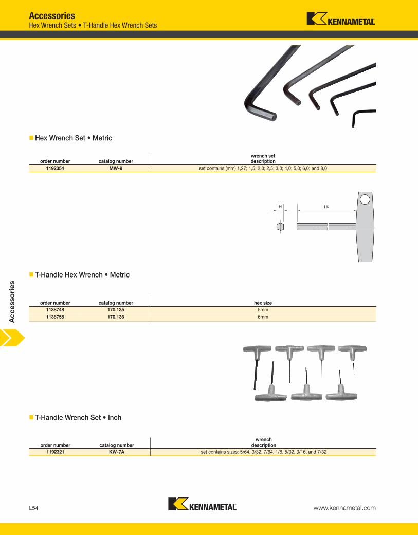
L54 www.kennametal.com
order number catalog numberwrench set description
1192354 MW-9 set contains (mm) 1,27; 1,5; 2,0; 2,5; 3,0; 4,0; 5,0; 6,0; and 8,0
order number catalog number hex size1138748 170.135 5mm1138755 170.136 6mm
order number catalog numberwrench
description1192321 KW-7A set contains sizes: 5/64, 3/32, 7/64, 1/8, 5/32, 3/16, and 7/32
� Hex Wrench Set • Metric
� T-Handle Hex Wrench • Metric
� T-Handle Wrench Set • Inch
AccessoriesHex Wrench Sets • T-Handle Hex Wrench Sets
Acc
esso
ries
KEN_TOOLINGSYSTEMS11_L054_L055.qxp:WIDIA 2:04 PM Page L54

L55www.kennametal.com
order number catalog number
1963869 driver
order number catalog numberhex size
Torx size
Torx Plus size
1138851 170.179 2,5mm — —
1150198 170.180 3mm — —
1138857 170.181 4mm — —
1962981 BT6 — 6 —
1963853 BT7 — 7 —
1963855 BT8 — 8 —
1963854 BT9 — 9 —
1963856 BT10 — 10 —
1138814 170.175 — 15 —
1138822 170.176 — 20 —
1994654 170.258 — 25 —
1984243 170.256 — 27 —
2244316 BT25IP — — 25IP
2244317 BT27IP — — 27IP
� Universal Bit Driver
� Driver Bit
Universal Bit Drivers • Driver BitsAccessories
Ac
ce
sso
rie
s
KEN_TOOLINGSYSTEMS11_L054_L055.qxp:WIDIA 11:45 AM Page L55

L56 www.kennametal.com
AccessoriesOpen-Ended Wrenches
• Standard open-ended wrenches.
� Wrench OEW • Metric
� Wrench OEW • Inch
order number catalog number DRVS
1284020 OEW9M 9mm
1284011 OEW13M 13mm
1174217 OEW16M 16mm
1197387 OEW19M 19mm
1192371 OEW24M 24mm
1186649 OEW25M 25mm
1284014 OEW30M 30mm
1284015 OEW32M 32mm
order number catalog number DRVS
1025533 OEW044 7/16
1025544 OEW050 1/8
1025546 OEW062 5/8
1025547 OEW068 11/16
1025548 OEW075 3/4
1025550 OEW088 7/8
1025551 OEW094 15/16
1025552 OEW100 1
1025553 OEW106 1 1/16
1025574 OEW112 1 1/8
1025575 OEW119 1 3/16
1025576 OEW125 1 1/4
1025674 OEW138 1 3/8
1025581 OEW150 1 1/2
1025582 OEW162 1 5/8
1025583 OEW168 1 11/16
1025604 OEW175 1 3/4
1025605 OEW188 1 7/8
1025607 OEW225 2 1/4
1025608 OEW250 2 1/2
Ac
ce
sso
rie
s
KEN_TOOLINGSYSTEMS11_L056_L057.qxp:WIDIA 11:46 AM Page L56

L57www.kennametal.com
order number catalog number DSWC
3367387 PSW52M 58,0mm - 62,0mm
1284310 PSW58M 52,0mm - 55,0mm
1192392 PSW68M 68,0mm - 75,0mm
1284311 PSW80M 80,0mm - 90,0mm
order number catalog number DSWC
1013497 PSW350 3 1/2
AccessoriesPin Spanner Wrenches • Hook Spanner Wrenches
• Standard pin spanner wrenches.
� Wrench PSW • Metric
� Wrench PSW • Inch
order number catalog number DSWC
1273813 HSW25M 25,0mm - 28,0mm
1273814 HSW34M 34,0mm - 36,0mm
1192229 HSW45M 45,0mm - 50,0mm
1192230 HSW58M 58,0mm - 62,0mm
1273815 HSW68M 68,0mm - 75,0mm
1192231 HSW80M 80,0mm - 90,0mm
• Standard hook spanner wrenches.
� Wrench HSW • Metric
Ac
ce
sso
rie
s
KEN_TOOLINGSYSTEMS11_L056_L057.qxp:WIDIA 11:46 AM Page L57

L58 www.kennametal.com
Rapid Rapid Plus
order number catalog number driver length KM size KM size
2030659 12146032300 3/8" Square 250 KM40™ —
2030660 12146032400 1/2" Square 250 KM50™ KM40 and KM50
2030661 12146032500 1/2" Square 400 KM63™ KM63
Rapid Rapid Plus
order number catalog number driver hex size KM size KM size
2031858 12146032600 3/8" Square 10 KM40 —
2031859 12146032700 1/2" Square 12 KM50 —
2031860 12146032800 1/2" Square 17 KM63 KM40
2067373 12146033500 1/2" Square 22 — KM50 and KM63
AccessoriesRapid and Rapid Plus Wrenches
� Rapid and Rapid Plus Wrenches
� Drive Sockets
NOTE: Wrench and drive socket must be ordered separately.
Ac
ce
sso
rie
s
KEN_TOOLINGSYSTEMS11_L058_L059.qxp:WIDIA 11:46 AM Page L58

Experience the advantages at your Authorized Kennametal Distributor or at www.kennametal.com.
www.kennametal.com
ERICKSON™ & KM™
• Most accurate chuck, ≤3μm (.0001"), achieves maximum performance from your cutting edge.
• Inherent dampening design extends tool life and improves surface finish.
• Pre-balanced to high specifications.
• Versatile as a collet chuck with the use of reduction sleeves.
For hydraulic chucks — ERICKSON and KM — the industry names you can trust.
Names You Can Trust
KEN_TOOLINGSYSTEMS11_L058_L059.qxp:WIDIA 11:46 AM Page L59