Embed Size (px)
Citation preview
Innovative Design of Francis Turbine for Sediment Laden Water
Krishna Prasad Shrestha1
Bhola Thapa1,
Ole Gunnar Dahlhaug2
Hari P. Neopane1
Biraj Singh Thapa1
1Dept. Mechanical Engineering, Kathmandu University,
P.O. Box 6250, Dhulikhel, Nepal2 Dept. Energy&Process Engineering, Norwegian
University of Science and Technology,
NTNU, Trondheim, 7491, Norway
Email: [email protected]
International Conference on TIM, 2012, Nepal
Outline
• Introduction• Objectives• Methodology
– Design of Francis runner– Core design process– Fluid Structure Interaction (FSI)
• Limitations• Results and Discussion• Conclusions and Recommendation
2
International Conference on TIM, 2012, Nepal
Introduction
• Hydro turbine running in the Himalayas and Andes Mountain of the South America are facing the same challenges of sediment erosion
• Jhimruk power plant can be considered a severe one in Nepal
• Renewable Nepal project, KU and Water power Laboratory, NTNU has developing Matlab based software called Khoj
• Khoj facilitates to produce preliminary design data for Francis turbine with accountability of sediment erosion
• CFD and FSI analysis has greater roll on improvement of hydraulic machine design and performance analysis
3
International Conference on TIM, 2012, Nepal
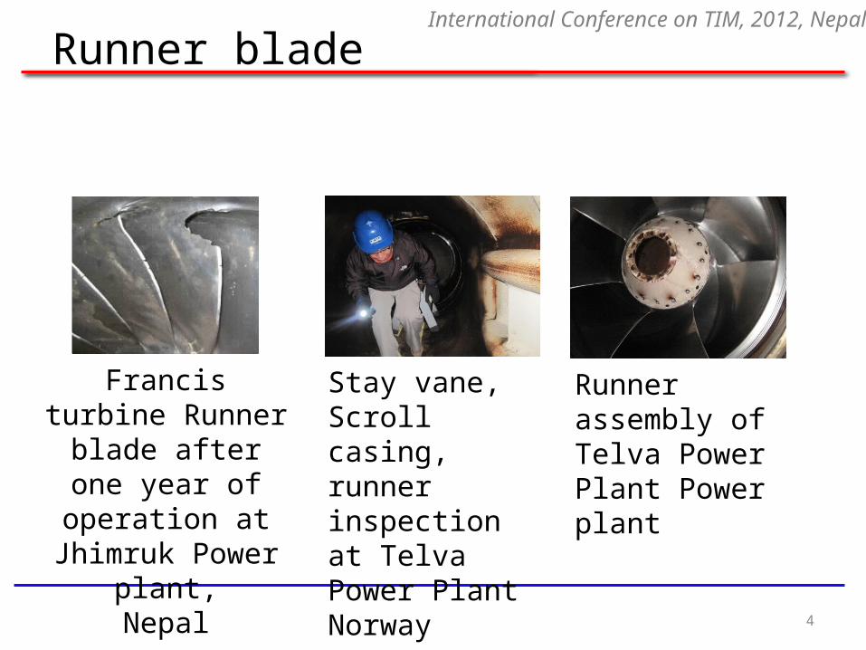
Runner blade
4
International Conference on TIM, 2012, Nepal
Francis turbine Runner blade after
one year of operation at Jhimruk
Power plant,Nepal
Runner assembly of Telva Power Plant Power plant
Stay vane, Scroll casing, runner inspection at Telva Power Plant Norway

Objectives
• To analysis the impact of sand erosion on Francis turbine.
• To identify the possible solution for the minimizing effect of erosion on turbine.
• To innovate optimization on Francis Turbine design.
• To design and develop new Francis turbine.
5
International Conference on TIM, 2012, Nepal
Design of Francis runner
6
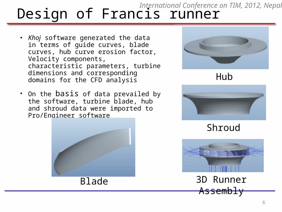
• Khoj software generated the data in terms of guide curves, blade curves, hub curve erosion factor, Velocity components, characteristic parameters, turbine dimensions and corresponding domains for the CFD analysis
• On the basis of data prevailed by the software, turbine blade, hub and shroud data were imported to Pro/Engineer software
Hub
Shroud
3D Runner AssemblyBlade
International Conference on TIM, 2012, Nepal
Core design process
7
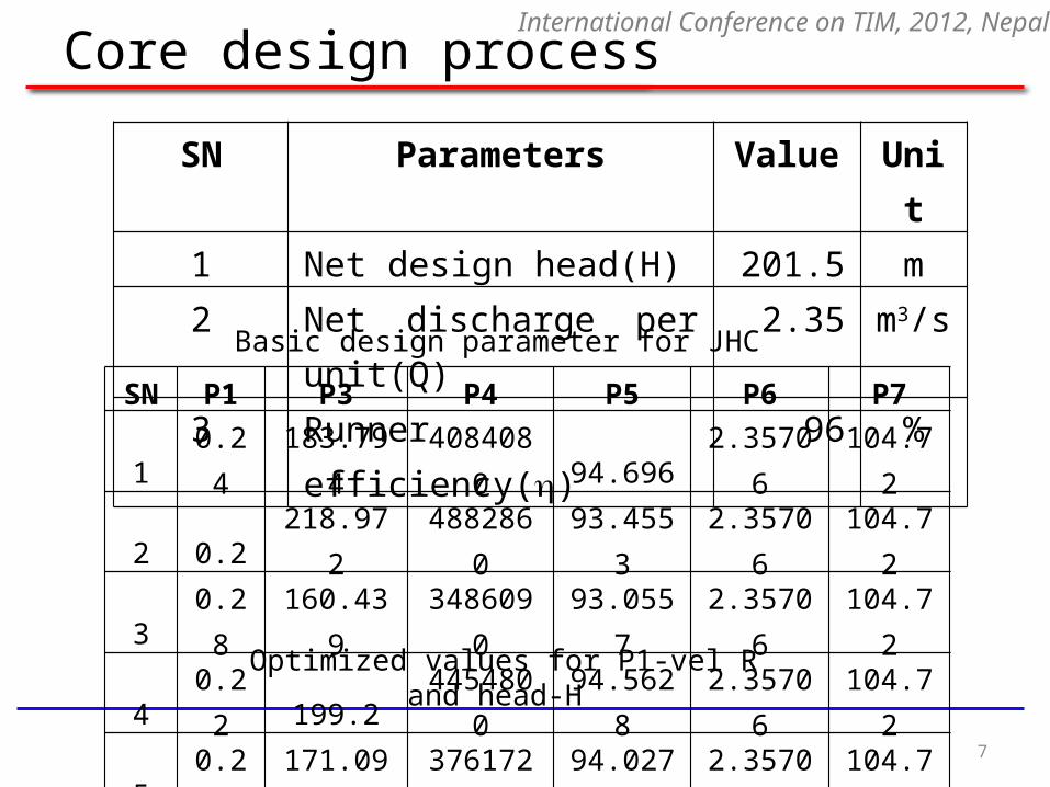
SN Parameters Value Unit1 Net design head(H) 201.5 m2 Net discharge per unit(Q) 2.35 m3/s3 Runner efficiency() 96 %
Basic design parameter for JHC
SN P1 P3 P4 P5 P6 P7
1 0.24 183.794 4084080 94.696 2.35706 104.72
2 0.2 218.972 4882860 93.4553 2.35706 104.72
3 0.28 160.439 3486090 93.0557 2.35706 104.72
4 0.22 199.2 4454800 94.5628 2.35706 104.72
5 0.26 171.097 3761720 94.0276 2.35706 104.72
Optimized values for P1-vel R and head-H
International Conference on TIM, 2012, Nepal
Core design process
8
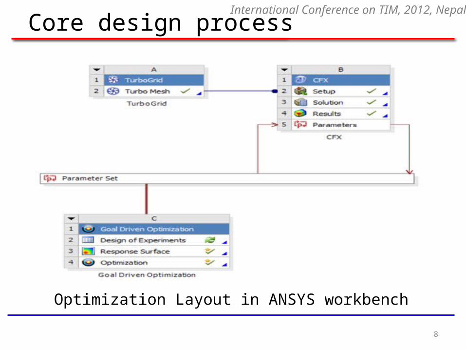
Optimization Layout in ANSYS workbench
International Conference on TIM, 2012, Nepal
Core design process
9
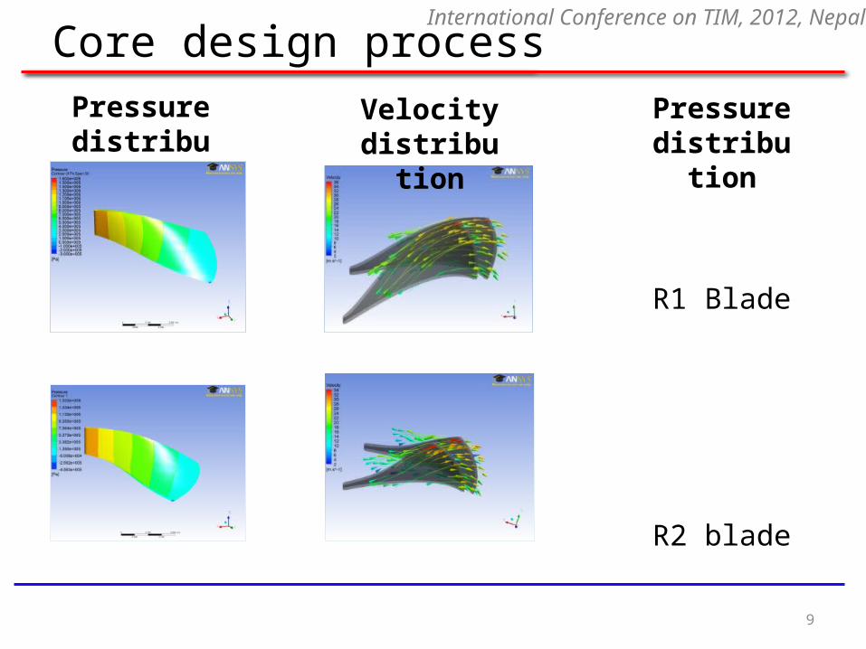
Pressure distribution
Pressure distribution
R1 Blade
R2 blade
Velocity distribution
International Conference on TIM, 2012, Nepal
Core design process
10
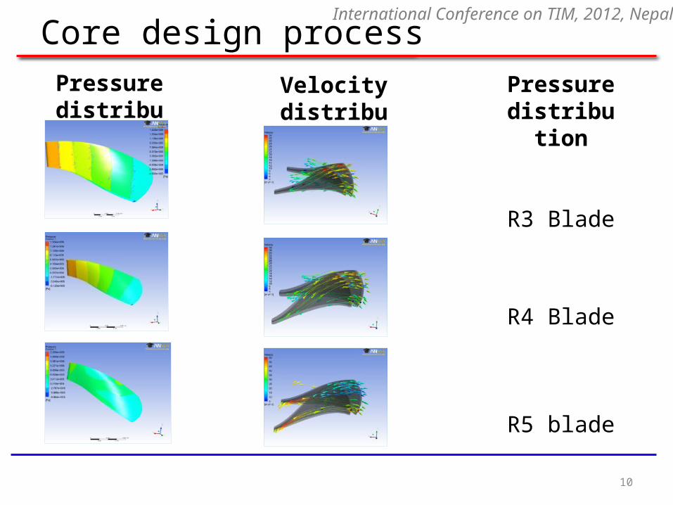
Pressure distribution
Pressure distribution
R3 Blade
R4 Blade
R5 blade
Velocity distribution
International Conference on TIM, 2012, Nepal
Core design process
11
International Conference on TIM, 2012, Nepal
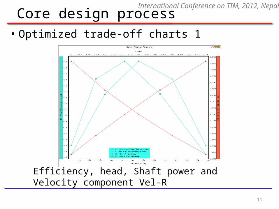
Efficiency, head, Shaft power and Velocity component Vel-R
• Optimized trade-off charts 1

Core design process
12
• Optimized trade-off charts 2
Efficiency, Flow, Shaft Power and Velocity component Vel-R
International Conference on TIM, 2012, Nepal
Core design process
13
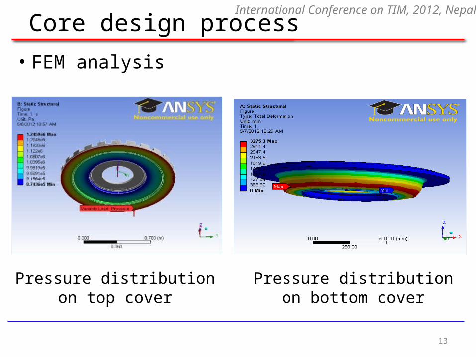
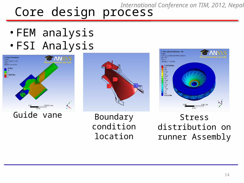
• FEM analysis
Pressure distribution on top cover
Pressure distribution on bottom cover
International Conference on TIM, 2012, Nepal
Core design process
14
• FEM analysis• FSI Analysis
Guide vane Boundary condition location
Stress distribution on runner Assembly
International Conference on TIM, 2012, Nepal
Core design process
15
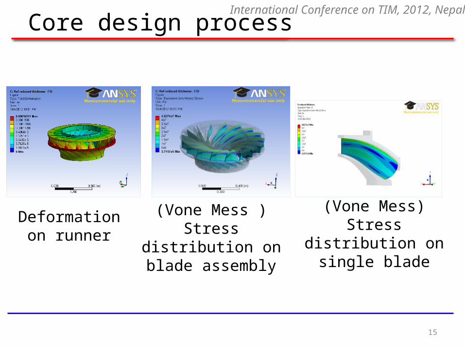
Deformation on runner
(Vone Mess ) Stress distribution on blade
assembly
(Vone Mess) Stress distribution on single
blade
International Conference on TIM, 2012, Nepal
Limitations
• Optimization was performed only one set of blade profile.
• FSI analysis was performed only on Francis turbine runner assembly.
• During the FSI analysis, Unidirectional Coupling was chosen, considering there was no large deformation on runner.
16
International Conference on TIM, 2012, Nepal
Results and Discussion
• Optimization was performed on CFD that signifies reducing simulation and cost of design
• Trade-off chart determines the trade-off points which is used to show the relation between variables
• Pressure distribution and velocity at trailing were observed by using CFD analysis
• R2 Blade was selected for FSI analysis since it has found uniform pressure distribution as well as relatively lower velocity
• FEM analysis was performed on guide vane, upper and lower cover
• Unidirectional coupled FSI analysis prevailed that total deformation of runner assembly was 0.00016931m which is safe for structural steel
17
International Conference on TIM, 2012, Nepal
Conclusion and Recommendation
• Erosion problem on Francis turbine due to sand laden water cannot be stopped completely by current technology but it can be minimized to the acceptable limit.
• Use of FEM, CFD and FSI tool reduce the design process and simulation time meticulously.
• New design processes found to be more sophisticated than the traditional way of design for the Francis turbine.
• Simulated result predicted that the new design method can accommodate sand erosion problem in more sophisticated way.
• It is recommended that simulation should be done in whole turbine unit and for better prediction two-way simulation is more reliable.
18
International Conference on TIM, 2012, Nepal
Recommendation
• It is recommended that simulation should be done in whole turbine unit and for better prediction two-way simulation is more reliable.
• Technological challenges and opportunities that recognize due to innovative design of Francis turbine should adopt by the turbine manufacturers.
19
Thank you very much for your time and attention!!!
Any queries???
20
International Conference on TIM, 2012, Nepal