Embed Size (px)
Citation preview

Innovative Flow Control Concepts for Drag Reduction
John C. Lin1 NASA Langley Research Center, Hampton, VA, 23681, USA
Edward A. Whalen2
The Boeing Company, Boeing Research & Technology, Hazelwood, MO, 63042, USA
Jenna L. Eppink3, Emilie J. Siochi4, Michael G. Alexander5, Marlyn Y. Andino6 NASA Langley Research Center, Hampton, VA, 23681, USA
Abstract This paper highlights the technology development of two flow control concepts for aircraft drag reduction. The NASA Environmentally Responsible Aviation (ERA) project worked with Boeing to demonstrate these two concepts on a specially outfitted Boeing 757 ecoDemonstrator during the spring of 2015. The first flow control concept used Active Flow Control (AFC) to delay flow separation on a highly deflected rudder and increase the side force that it generates. This may enable a smaller vertical tail to provide the control authority needed in the event of an engine failure during takeoff and landing, while still operating in a conventional manner over the rest of the flight envelope. Thirty-one sweeping jet AFC actuators were installed and successfully flight-tested on the vertical tail of the 757 ecoDemonstrator. Pilot feedback, flow cone visualization, and analysis of the flight test data confirmed that the AFC is effective, as a smoother flight and enhanced rudder control authority were reported. The second flow control concept is the Insect Accretion Mitigation (IAM) innovation where surfaces were engineered to mitigate insect residue adhesion on a wing’s leading edge. This is necessary because something as small as an insect residue on the leading edge of a laminar flow wing design can cause turbulent wedges that interrupt laminar flow, resulting in an increase in drag and fuel use. Several non-stick coatings were developed by NASA and applied to panels that were mounted on the leading edge of the wing of the 757 ecoDemonstrator. The performance of the coated surfaces was measured and validated by the reduction in the number of bug adhesions relative to uncoated control panels flown simultaneously. Both flow control concepts (i.e., sweeping jet actuators and non-stick coatings) for drag reduction were the culmination of several years of development, from wind tunnel tests to flight tests, and produced valuable data for the advancement of modern aircraft designs. The ERA systems analysis studies performed by NASA indicated that AFC-enhanced vertical tail could produce ~0.9% drag reduction for a large twin aisle aircraft and IAM coatings could enable ~1.2% drag reduction recovery for a potential total drag reduction of ~3.3% for a single aisle aircraft with a natural laminar flow (NLF) wing design.
Nomenclature AFC = Active Flow Control APU = auxiliary power unit CFD = computational fluid dynamics Cμ = momentum coefficient, %
1 Aerospace Engineer, Flow Physics and Control Branch, MS 170, AIAA Associate Fellow 2 Manager, Boeing Research & Technology, Mail Stop: S306-4030, AIAA Senior Member 3 Aerospace Engineer, Flow Physics and Control Branch, MS 170, AIAA Member 4 Aerospace Engineer, Advanced Materials and Processing Branch, MS 397 5 Systems Engineer, Systems Engineering & Engineering Methods Branch, MS 434 6 Aerospace Engineer, Flow Physics and Control Branch, MS 170, AIAA Senior Member
https://ntrs.nasa.gov/search.jsp?R=20160007668 2018-05-22T11:13:17+00:00Z

2
ERA = Environmentally Responsible Aviation ES = engineered surface GTF = Geared Turbofan IAM = Insect Accretion Mitigation ITD = Integrated Technology Demonstration KDF = knockdown factor, % laminar flow reduction with respect to the baseline NLF case LaRC = Langley Research Center LFC = Laminar Flow Control LTA = large twin aisle MAC = mean aerodynamic chord NFAC = National Full-Scale Aerodynamics Complex NLF = natural laminar flow SA = single aisle T&W = tube and wing TRL = technology readiness level β = sideslip angle, degrees %ΔCy = % difference in side force coefficient with respect to no AFC
Introduction
HE NASA Environmentally Responsible Aviation (ERA) project’s main purpose is to mature technologies focused on simultaneously reducing fuel consumption, nitrogen oxides from emissions, and community noise
profiles of modern passenger and cargo transport aircraft.1,2 Aircraft drag reduction is continuing to be a top priority for commercial, military, and general aviation, because it translates directly to reduced fuel burn. Since skin friction (or viscous drag) contributes to about 50% of the total drag of a transport aircraft,3,4 its reduction has the potential of achieving substantial decrease in fuel burn. Indirect benefits of the aircraft drag reduction (or lower fuel consumption) include increased range, heavier payloads, and lower engine emissions. The ERA project is interested in innovative approaches for aircraft drag reduction and it has sponsored a number of technology maturation efforts since 2010 that were aimed to improve aircraft fuel efficiency. ERA Phase 2 occurred from 2012 to 2015, where research was conducted to mature technologies from technology readiness level (TRL) of 3 to 6 through Integrated Technology Demonstrations (ITDs) with an emphasis on those technologies that can be matured to a higher readiness level and those that have demonstrated commercial viability in the 2020 to 2025 timeframe.
AFC-Enhanced Vertical Tail One of these innovative drag reduction approaches sponsored by the ERA project involved the use of AFC technology5,6 to reduce the size (i.e., wetted area) of the vertical tail,7-16 directly leading to a decrease in drag, as well as a reduction in fuel consumption and greenhouse gas emissions (nitrogen oxide). The vertical tail on a modern, multi-engine commercial transport aircraft is sized to overcome the rare instance of engine failure during takeoff and low speed climb that includes crosswind conditions. It must be sufficiently large to generate enough side force to counteract the asymmetric thrust of the operational engine at full power and the drag of the windmilling fan of the failed engine (see Fig. 1) while maintaining directional control. It may therefore be oversized for normal operations, particularly for cruise conditions. In addition, the vertical tail is usually sized for the shortest version in an aircraft model family, which effectively makes the common vertical tail oversized for the stretched versions (longer moment arm) in the family. Due to these design accommodations, the vertical tail adds drag and weight, thus increasing the fuel consumption of the entire aircraft family. AFC technology can be employed to delay flow separation over a highly deflected rudder and increase the side force that it generates. This may enable a smaller vertical tail to provide the control authority needed during an emergency, while still operating in a conventional manner over the rest of the flight envelope. Active flow control could be used on the shorter members of an aircraft family, but may not be needed on stretched variants. A system integration study on a mid-sized twin aisle airplane indicated that such a vertical tail design could result in drag reduction and fuel savings. For example, a 17% increase in side force would allow designers to scale-down the vertical tail of a mid-sized twin aisle airplane by about 15% and reduce aircraft drag by ~0.4%, which could produce an estimated fuel burn reduction of 15,500 gallons/airplane/year.16
T
3
Figure 1. Necessary trim settings of an airplane in case of engine failure.
Insect Accretion Mitigation The second innovative drag reduction approach sponsored by the ERA project involved the use of an engineered surface (ES) with non-stick coatings that mitigate insect residue adhesion on a wing’s leading edge to enable larger regions of laminar flow, and therefore less skin friction drag. A number of studies suggested that Laminar Flow Control (LFC) — the delaying of laminar-turbulent boundary-layer transition — could produce fuel savings of the order of ~5% or more for a long haul transport aircraft.17-19 If a natural laminar flow surface could be manufactured for a wing’s leading edge,20 the maintainability of laminar flow surfaces is an issue that requires careful consideration for practical applications of LFC technology. Since the transition of boundary layer flows from laminar to turbulent is sensitive to surface pressure gradients, the pressure gradients under load and any localized pressure gradients due to surface imperfections (e.g., steps/gaps, waviness, insect residue, etc.) must be known accurately. While there has been some success in developing computational approaches21,22 to determine allowable surface excrescences, laminar flow design is based primarily on empirical knowledge and this is an area of continuing research.23,24 Transition, particularly crossflow-induced, is extremely sensitive to leading edge surface roughness, as stationary crossflow vortices draw their initial amplitudes from surface roughness.20 Unavoidable surface roughness (e.g., insect contamination during takeoff) could deteriorate laminar flow performance. Historically, systems for insect impact avoidance (e.g., leading-edge flaps or slats) have been used in laminar flow research flight tests. More recently, ERA sponsored research to develop engineered surfaces that could mitigate insect residue adhesion, as reported by Wohl et al.25
The potential benefits of the two drag-reduction concepts — AFC-Enhanced Vertical Tail and Insect Accretion Mitigation — were significant enough to warrant NASA ERA project investments for technology maturation. An ERA sub-project designated as ITD 12A+ AFC Enhanced Vertical Tail plus Advanced Wing Flight Experiment26 was implemented to achieve the technology maturation objectives. This paper highlights the TRL maturation process of the two flow control concepts for aircraft drag reduction, with special emphasis given to the recent successful flight tests on the ecoDemonstrator.
Drag Reduction Concept 1: AFC-Enhanced Vertical Tail Technology Maturation Various AFC methods have been researched and have shown different degrees of effectiveness depending on
the application.5 For the vertical tail size reduction (drag reduction) applications, the capabilities of AFC have been tested in wind tunnels on vertical fin models (both subscale and full-scale) and flight-tested on an airplane at relevant conditions.7-15 The goal of these studies was to use AFC to substantially increase the control authority of the vertical tail on a commercial transport airplane. A technology maturation roadmap is summarized in Fig. 2, illustrating TRL and three phases of technology development: subscale wind-tunnel test, full-scale wind tunnel test, and flight test.

4
Figure 2. AFC-enhanced vertical tail technology maturation roadmap (summarized).
Subscale Wind Tunnel Test (TRL 3 to 4)
At the beginning of the ERA Phase 1, two AFC devices (synthetic jet and sweeping jet) were identified that could offer the potential side force enhancement needed to reduce the vertical tail size. Boeing sponsored low speed wind tunnel tests at Rensselaer Polytechnic Institute (RPI) to evaluate the effectiveness of synthetic jet AFC.7-9 NASA sponsored and evaluated the sweeping jet AFC concept that was tested at the California Institute of Technology (Caltech) low speed wind tunnel.10-12 Because of their significantly higher exit jet momentum coefficient (Cμ) and corresponding jet velocity, the sweeping jet concept outperformed the synthetic jet at large rudder deflection (30°) and zero side slip angle (β) — up to 50% side force enhancement (Cμ=1.7%) for the sweeping jets versus 20% side force enhancement (Cμ=0.248%) for the synthetic jets. A decision was made by the NASA/Boeing team to carry the sweeping jet AFC concept into Phase 2 for the subsequent full-scale AFC wind tunnel test, as the TRL was advanced from 3 to 4 (using the NASA TRL maturation definition). It was also decided to place the sweeping jets emitting from the trailing edge of the vertical stabilizer (instead of issuing from the rudder leading edge) for the next phase due to the simpler system integration prospect.
Full Scale Wind Tunnel Test (TRL 4 to 5) Following the Caltech subscale test, Boeing acquired a 757 vertical tail from an aircraft boneyard and modified it to be tested as a wind tunnel model at the National Full-Scale Aerodynamics Complex (NFAC) 40x80 foot wind tunnel located at NASA Ames Research Center.26 This tunnel has the capability of providing relevant flight conditions for the evaluation of the AFC-enhanced vertical tail system. The test permitted direct full-scale side force measurement achieved by the sweeping jet AFC, which enabled a direct comparison to the side force enhancement goal. Testing at the NFAC 40x80 wind tunnel using 37 sweeping jet actuators located along the rudder hinge line (right side), demonstrated control authority enhancement of a full-scale vertical tail. The effects of sweeping jet actuator parameters such as exit jet momentum, air source pressure and mass flow, and actuator spacing and coverage across a range of test points representative of takeoff and landing conditions were explored.13,14 The full-scale test results showed the AFC system provided a sufficient level of performance enhancement (~20% increase in side force) that could be obtained within the limits of the air supply already present on the 757 ecoDemonstrator — e.g., auxiliary power unit (APU) compressor. The test results also indicated that the sweeping jet AFC performance exceeded the side force goal by 50% under some conditions. In addition, AFC configuration study indicated not all 37 sweeping jet actuators were required to meet or exceed the original 20% side force enhancement goal. A 31-actuator pattern obtained through deactivation of 6 actuators near the tip was selected as the best configuration. This reduction in the number of actuators could result in a potential AFC system simplification and weight reduction. The parametric variations tested provided data that not only served to validate the assumption that the APU could provide the goal of 20% side

5
force enhancement for the subsequent flight test, but provided a useful database for designing AFC systems that are not constrained by the APU. This database allows NASA ERA system analysts to search for better implementations for a new aircraft unconstrained by the practical considerations of retrofit testing. The successful full-scale testing of the AFC-enhanced vertical tail technology cleared the way for a follow-on flight demonstration, as the TRL was advanced from 4 to 5. ecoDemonstrator AFC-Enhanced Vertical Tail Flight Test (TRL 5 to 6) An AFC-enhanced vertical tail flight test was performed in the spring of 2015 on a specially outfitted Boeing 757 airplane called the 757 ecoDemonstrator.15 Leveraging the knowledge gained from the full-scale wind-tunnel test at NFAC, 31 sweeping jet actuators were installed on the starboard (right) side of the vertical tail of the ecoDemonstrator. The actuator nozzles (exits) were located along the trailing edge of the vertical fin, where the nozzles were aligned normal to the rudder hinge line and pointed downstream. An external view of the AFC configuration is shown in Fig. 3. The red dashed line shows the upstream end of the AFC actuator. The actuator numbers are placed just upstream of the actuator nozzles, and the white dots located primarily on the rudder are for flow visualization tufts.
Figure 3. Sweeping jet actuator arrangement on the 757 vertical tail.
The purpose of the test was to demonstrate and validate that the sweeping jet AFC technology could generate significantly more side force on a commercial transport’s vertical tail for simulated engine-out sideslip conditions that could occur during takeoff. These flights included steady heading sideslips as well as simulated engine-out trims and engine-out decelerations. Variations in sweeping-jet arrangements and flow rates were also explored during the flight test.
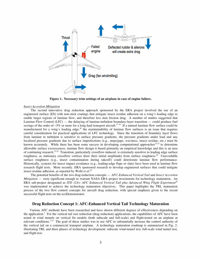
The AFC modifications were installed on the stabilizer and aft fuselage of the ecoDemonstrator. Bleed air from the APU compressor provided system mass flow. An air-to-air heat exchanger was mounted underneath the aft body of the airplane to cool the APU air to comply with fin and rudder structural requirements. Ducting within the fuselage routed the air to ducting embedded in the stabilizer. The ducting in the stabilizer branched into smaller tubes to bring the air to panel-mounted sweeping jet AFC nozzles. Instruments on board the ecoDemonstrator flight-test airplane were used to evaluate the performance of the AFC-enhanced vertical tail in six flights over the Strait of Juan de Fuca, just north of Seattle, WA. Figures 4 (a) and 4 (b) illustrate the 757 ecoDemonstrator airplane with AFC modifications during various portions of the test program.
6
(a) 757 ecoDemonstrator during Functional Check Flight.
(b) Boeing T-33 Chase Plane providing photo support during flight test.
Figure 4. Boeing 757 ecoDemonstrator during flight test.
The flow cone photos taken from the chase plane were digitally overlaid to provide a snapshot of the airflow on the vertical tail during a given test condition. The attachment point of each cone was aligned in the composite photo. Generally these photos represent one second of time and combine approximately five individual photos. Figure 5 illustrates the difference in the flow field when AFC is off and when it is on. When off, the cone orientation at many locations on the vertical fin does not coincide with the cone orientation in previous or subsequent photos taken within a fraction of a second of each other. This spreading or scattering in the composite photo indicates unsteady flow. When AFC is on, the cones from one picture to the next nearly coincide, indicating that AFC is positively affecting the airflow over the rudder surface. Overall, the flow cones on the vertical tail confirm that the AFC system reduces flow separation at high rudder deflections. Pilot feedback also confirmed the effectiveness of AFC, as smoother flight and enhanced rudder control authority were achieved. AFC effects on yawing moment, side force and rudder power were derived from the flight test data by applying Boeing proprietary methods to update the Company’s standard 757-simulation model. The analysis accounted for the asymmetrical wing geometry, AFC heat exchanger, and the AFC actuators on the right-hand side of the vertical fin as present on the baseline 757 ecoDemonstrator aircraft. Residuals relative to the standard 757-simulation model were adjusted to be similar between AFC-on and AFC-off flight-test cases. As a result, changes in rudder effectiveness due to AFC were isolated from asymmetries present in the 757 ecoDemonstrator baseline configuration.

7
Figure 5. Composite pictures of flow cones with AFC off (left) and on (right) for the flight conditions
indicated in the lower left corner. Figure 6 summarizes the relative increments in rudder effectiveness at various rudder deflections as a function of β within the achievable useable parameter space for the 31-actuator case at the maximum flow rate (100% mass flow). Note that in this figure, the rudder increments are shown in piece-wise linear segments between ‘break points’ used in constructing the multi-dimensional parameter space (i.e., β, rudder deflection, mass flow rate).
Figure 6. Predicted 757 ecoDemonstrator percentage increase in rudder effectiveness due to AFC based on
flight test and full-scale wind tunnel data (31 Actuators, 100% mass flow). Shaded area: no flight test data available.
�100% mass flow

8
These flight test results obtained within the 757 ecoDemonstrator testing envelope demonstrate a sizeable AFC benefit in rudder effectiveness. The test results indicate a 6% improvement at 30° rudder deflection (β near +5°). At a given β, AFC impact on rudder effectiviness increases as rudder deflection increases towards 30°. Consistent with expectation, the impact of AFC significantly increases as β approaches zero and negative side slip angles. A side force increase of 13% to 16% was estimated at 30° rudder deflection for critical sideslip range between β = 0° and -7.5°, which could enable a ~12% area reduction for the vertical tail. The flight test results confirmed the effectiveness of AFC to enable the reducion of vertical tail’s size, and therefore as a viable drag reduction concept. The successful flight test of the AFC-enhanced vertical tail technology enabled its TRL to advance from 5 to 6. Based on the ecoDemonstrator flight test and NFAC full-scale test results, a vehicle level assessment was conducted by the NASA ERA system analysts to evaluate AFC-enhanced vertical tail technology impact on a large twin aisle (LTA), tube and wing (T&W) commercial aircraft.26 The impact of the AFC-enhanced vertical tail technology as projected to FY2025 is estimated to be a ~0.9% cruise drag reduction for a typical LTA T&W class aircraft. Figure 7 illustrates the side force increase and estimated total cruise drag reduction during the ERA phase 2, which was typically around 1% based on test results at different TRL maturation stages.
Figure 7. TRL maturation roadmap and estimated drag reduction for AFC-enhanced vertical tail
technology.
Drag Reduction Concept 2: Insect Accretion Mitigation Technology Maturation The Insect Accretion Mitigation (IAM) technology also falls within the ERA project element and supports its drag reduction goals. For a successful implementation of laminar flow on wings, an operational challenge that has to be addressed is the premature boundary layer transition due to roughness induced by insect contamination on the aircraft’s wing. The consequence of an early transition to turbulent flow is an increase in drag, which directly impacts fuel consumption. The ERA-developed IAM coatings were tested to evaluate their efficacy in overcoming the aforementioned operational challenge. The IAM coatings were matured in a deliberate process, which started with the evaluation of a range of engineered surface compositions using a benchtop wind tunnel, then testing in a low speed wind tunnel at NASA Langley Research Center (LaRC), followed by flight tests on a NASA LaRC Falcon aircraft, and concluded with flying on the right wing of the Boeing 757 ecoDemonstrator. At each testing or technology maturation step, the coatings were examined for their insect accretion denial capability. Coatings found to be effective were selected for continued maturation. The IAM technology maturation roadmap is shown in Fig. 8. A timeline and milestone summary chart is presented in the figure to illustrate TRL and three phases of technology development.

9
Figure 8. IAM technology maturation roadmap (summarized).
Low Speed Wind Tunnel Test (TRL 3 to 4) During the ERA Phase 1 activities, over 200 chemical and topographical surface coating combinations, including commercial and experimental compositions, were screened on a benchtop wind tunnel. The evaluation consisted of impacting the surfaces with live fruit flies traveling at ~150 mph to mimic conditions encountered during takeoff and landing. Profilometry was used to measure the area and height of the insect residues. Effective surfaces yielded much smaller residue areas and heights. At the conclusion of these tests, the IAM coating TRL was assessed to be 2. To continue the evaluation of these engineered surfaces in more realistic use environments, initial low speed wind tunnel tests were conducted in NASA LaRC Basic Aerodynamic Research Tunnel (BART). The results revealed several promising coatings that reduced insect residue accumulation. At the conclusion of the Phase 1 BART test, IAM coating TRL was advanced from 2 to 3 for ERA Phase 2. At the beginning of Phase 2 of the ERA project, the coatings underwent environmental durability testing that mimicked atmospheric conditions the coating needed to endure during routine use. This testing involved long-term aging in an environmental chamber designed to expose the coatings to humidity and ultraviolet radiation. The chamber was located at NASA LaRC. The downselected coatings from this test were chosen based upon their ability to reduce insect residue adhesion, environmental durability, and minimal maintenance. Following the durability tests, the coatings underwent further wind tunnel testing in the BART. At the conclusion of the Phase 2 BART test, the data were reviewed/analyzed and the IAM coating TRL was matured from 3 to 4. Falcon Flight Test (TRL 4 to 5) An initial flight test opportunity presented itself using the NASA Langley Falcon or HU-25 Huron aircraft. Several coatings were applied to aluminum substrates and taped to the Falcon wing’s leading edge. The flight profiles used for the flight test were chosen to maximize insect impacts. Following the Falcon flight test, data were reviewed/analyzed, and the effective coating compositions were further downselected and the coating TRL was increased from 4 to 5. The technology maturation process yielded 5 coatings subsequently flown on the Boeing 757 ecoDemonstrator.

10
ecoDemonstrator Insect Accretion Mitigation Flight Test (TRL 5 to 6) The IAM flight test was performed at Shreveport Regional Airport (KSHV) in Shreveport, LA. IAM surfaces consisted of five compositions which were downselected from over 200 compositions studied during the life of the project. They are described in Table 1. The surfaces flown were chosen to permit the investigation of the influence of surface chemistry and surface topography on insect residue adhesion mitigation. For the IAM ecoDemonstrator fight tests, the coating materials were prepared at LaRC and applied onto the engineered surfaces (ES) at Boeing in Seattle, and the completed ES panels were subsequently shipped to Shreveport. Part of the ES shipment were “control panels”, which were blank, uncoated aluminum substrates. The control panels were used to assess insect accretion on the ES, based on the assumption that coated and uncoated panels positioned adjacent to each other would encounter similar insect population densities during flight. To attach the ES and control panels to the wing slats, Boeing developed a taping process that held the panels in place during flight, yet allowed for removal post flight without disturbing the insect residues. The 757 leading edge slat numbering scheme can be seen in Fig. 9. Engineered surfaces were taped to the slats 8 and 9 in the layout as indicated in Fig. 10.
Table 1. Description of formulations down selected for flight testing on ecoDemonstrator.
Formulation Description Salient Feature Variable
IAMC-5A Modified commercially available epoxy
Will act as the baseline for surface chemical and topographical modifications Baseline
IAMC-5B Modified commercially available epoxy with 1 filler
Surface topography modified with nanometer particulates
Surface topography
IAMC-5 Modified commercially available epoxy with 2 fillers
Surface topography modified with micrometer and nanometer particulates
Surface topography
IAMC-4 Research epoxy Introduction of potentially useful chemical functionalities beyond low surface energy moieties
Surface chemistry
IAMC-3 Research urethane Introduction of low surface energy moieties to urethane matrix
Surface chemistry
Figure 9. Boeing 757 slat numbering nomenclature.
11
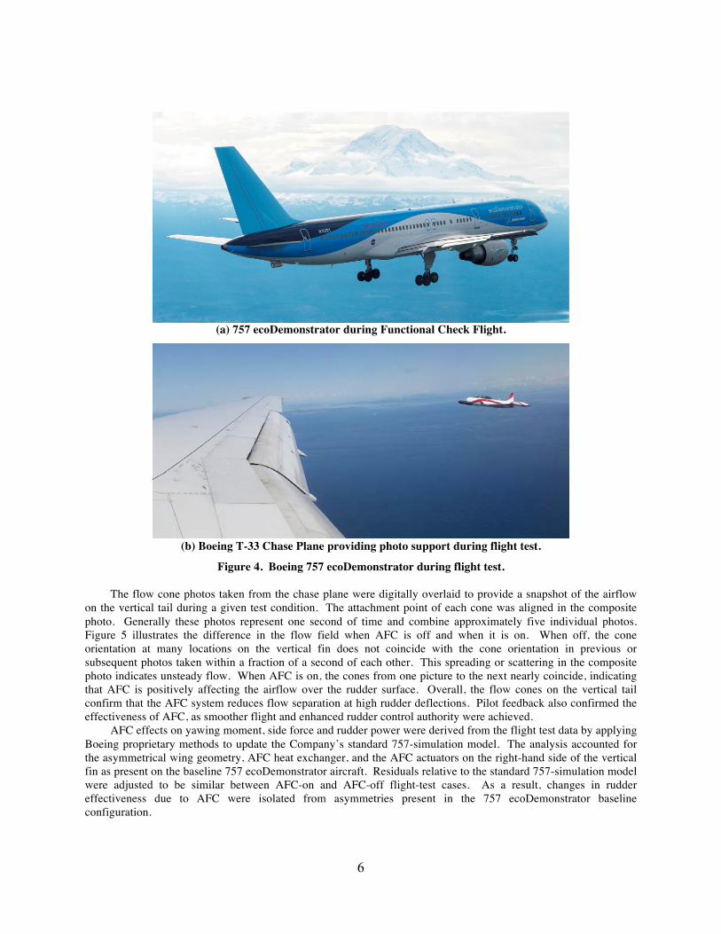
Figure 10. Engineered Surface layout on Slats 8 and 9.
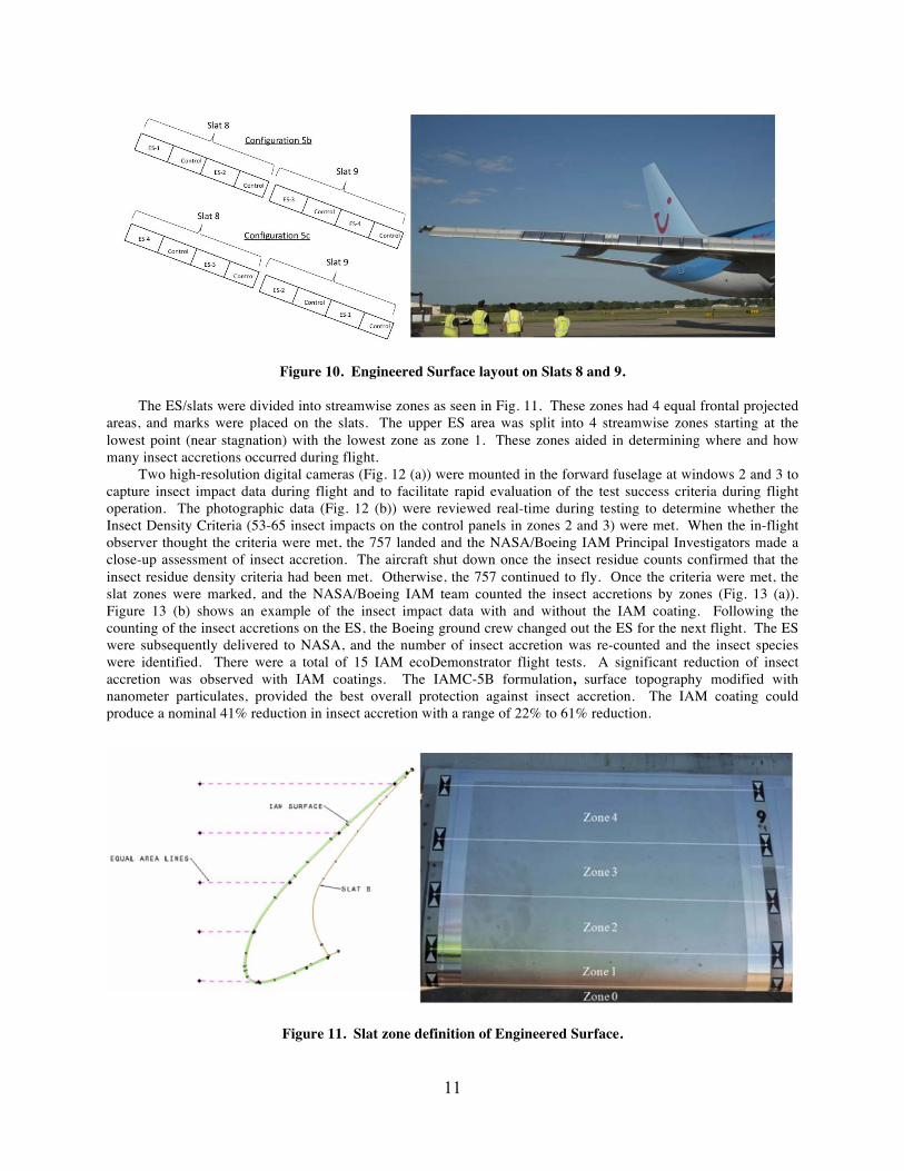
The ES/slats were divided into streamwise zones as seen in Fig. 11. These zones had 4 equal frontal projected areas, and marks were placed on the slats. The upper ES area was split into 4 streamwise zones starting at the lowest point (near stagnation) with the lowest zone as zone 1. These zones aided in determining where and how many insect accretions occurred during flight. Two high-resolution digital cameras (Fig. 12 (a)) were mounted in the forward fuselage at windows 2 and 3 to capture insect impact data during flight and to facilitate rapid evaluation of the test success criteria during flight operation. The photographic data (Fig. 12 (b)) were reviewed real-time during testing to determine whether the Insect Density Criteria (53-65 insect impacts on the control panels in zones 2 and 3) were met. When the in-flight observer thought the criteria were met, the 757 landed and the NASA/Boeing IAM Principal Investigators made a close-up assessment of insect accretion. The aircraft shut down once the insect residue counts confirmed that the insect residue density criteria had been met. Otherwise, the 757 continued to fly. Once the criteria were met, the slat zones were marked, and the NASA/Boeing IAM team counted the insect accretions by zones (Fig. 13 (a)). Figure 13 (b) shows an example of the insect impact data with and without the IAM coating. Following the counting of the insect accretions on the ES, the Boeing ground crew changed out the ES for the next flight. The ES were subsequently delivered to NASA, and the number of insect accretion was re-counted and the insect species were identified. There were a total of 15 IAM ecoDemonstrator flight tests. A significant reduction of insect accretion was observed with IAM coatings. The IAMC-5B formulation, surface topography modified with nanometer particulates, provided the best overall protection against insect accretion. The IAM coating could produce a nominal 41% reduction in insect accretion with a range of 22% to 61% reduction.
Figure 11. Slat zone definition of Engineered Surface.

12
(a) IAM cameras mounted in Windows 2 and 3. (b) Photo of Slat 8 ES from Window 3.
Figure 12. IAM inflight visualization apparatus.
(a) Post flight assessment of insect accretion. (b) Sample insect impact data from flight test.
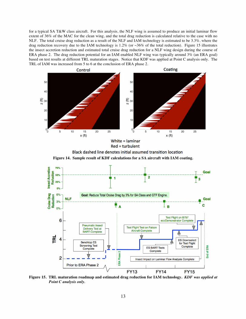
Figure 13. Counting insect impacts on the Engineered Surfaces. The IAM technology targeted a 12 million transition Reynolds number for an advanced single aisle (SA) vehicle. NASA ERA analysts estimated this technology translates to an upper wing surface chord laminar flow run of 36% of the mean aerodynamic chord (MAC). Using this transition Reynolds number as an anchor point, adjustments were made for the larger vehicles to account for the sweep and Mach number effects. For example, these adjustments resulted in an estimated transition Reynolds number of 9.5 million for the large twin aisle class vehicles, which translated to a 20% chord laminar flow run at the MAC. A knockdown factor (KDF) was applied to account for the disruptions of laminar flow due to bug hits on the leading edges of the wings and tails, where KDF is defined as the percent reduction in laminar flow from the baseline case. This was necessary in order to quantify the effect of the IAM coatings on the laminar flow extent. The analysis approach was similar to that used by Korntheuer et al.28 Data acquired from the ecoDemonstrator flight test were used to determine the number, height, and location of the insect residues with and without the IAM coating. These height distributions and the number of bug hits versus chord were then used, along with an assumed turbulence spreading angle, to estimate the KDF for several different swept-wing configurations. The results were highly dependent on the wing geometry, the assumed initial laminar flow extent, and the assumed bug-hit density. Figure 14 shows a sample result of KDF calculations for a SA aircraft with IAM coating. The KDF results presented in this paper were computed assuming a turbulence spreading angle of 5° half-angle and a bug-hit density of 5 hits per square foot. Without IAM coatings, the KDF for the advanced SA vehicle was estimated to be 48%, which means a 48% reduction of chord laminar flow due to bug hits. Thus, the transition front would move from 36% chord to 19% chord. With the IAM coating, this KDF is reduced to 25%, which would result in a transition front at 27% chord. Based on the KDF estimations, a vehicle level assessment was conducted by the NASA ERA system analysts to evaluate the impact of the NLF and IAM technology as projected to FY2025
13
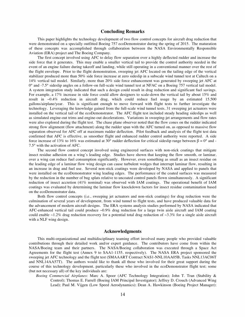
for a typical SA T&W class aircraft. For this analysis, the NLF wing is assumed to produce an initial laminar flow extent of 36% of the MAC for the clean wing, and the total drag reduction is calculated relative to the case with no NLF. The total cruise drag reduction as a result of the NLF and IAM technology is estimated to be 3.3%, where the drag reduction recovery due to the IAM technology is 1.2% (or ~36% of the total reduction). Figure 15 illustrates the insect accretion reduction and estimated total cruise drag reduction for a NLF wing design during the course of ERA phase 2. The drag reduction potential for an IAM enabled NLF wing was typically around 3% (an ERA goal) based on test results at different TRL maturation stages. Notice that KDF was applied at Point C analysis only. The TRL of IAM was increased from 5 to 6 at the conclusion of ERA phase 2.
Figure 14. Sample result of KDF calculations for a SA aircraft with IAM coating.
Figure 15. TRL maturation roadmap and estimated drag reduction for IAM technology. KDF was applied at
Point C analysis only.
14
Concluding Remarks This paper highlights the technology development of two flow control concepts for aircraft drag reduction that were demonstrated on a specially outfitted Boeing 757 ecoDemonstrator during the spring of 2015. The maturation of these concepts was accomplished through collaboration between the NASA Environmentally Responsible Aviation (ERA) project and The Boeing Company. The first concept involved using AFC to delay flow separation over a highly deflected rudder and increase the side force that it generates. This may enable a smaller vertical tail to provide the control authority needed in the event of an engine failure during takeoff and landing, while still operating in a conventional manner over the rest of the flight envelope. Prior to the flight demonstration, sweeping jet AFC located on the tailing edge of the vertical stabilizer produced more than 50% side force increase at zero sideslip in a subscale wind tunnel test at Caltech on a 14% vertical tail model. Similarly, more than 20% side force enhancement was generated by sweeping jet AFC at 0° and -7.5° sideslip angles on a follow-on full-scale wind tunnel test at NFAC on a Boeing 757 vertical tail model. A system integration study indicated that such a design could result in drag reduction and significant fuel savings. For example, a 17% increase in side force could allow designers to scale-down the vertical tail by about 15% and result in ~0.4% reduction in aircraft drag, which could reduce fuel usage by an estimated 15,500 gallons/airplane/year. This is significant enough to move forward with flight tests to further investigate the technology. Leveraging the knowledge gained from the full-scale wind tunnel tests, 31 sweeping jet actuators were installed on the vertical tail of the ecoDemonstrator. The AFC flight test included steady heading sideslips as well as simulated engine-out trims and engine-out decelerations. Variations in sweeping-jet arrangements and flow rates were also explored during the flight test. The chase plane observer noted that the flow cones on the rudder indicated strong flow alignment (flow attachment) along the rudder span with the AFC turned on, as opposed to massive flow separation observed for AFC off at maximum rudder deflection. Pilot feedback and analysis of the flight test data confirmed that AFC is effective, as smoother flight and enhanced rudder control authority were reported. A side force increase of 13% to 16% was estimated at 30° rudder deflection for critical sideslip range between β = 0° and -7.5° with the activation of AFC. The second flow control concept involved using engineered surfaces with non-stick coatings that mitigate insect residue adhesion on a wing’s leading edge. Studies have shown that keeping the flow smooth, or laminar, over a wing can reduce fuel consumption significantly. However, even something as small as an insect residue on the leading edge of a laminar flow wing design can cause turbulent wedges that interrupt laminar flow, resulting in an increase in drag and fuel use. Several non-stick coatings were developed by NASA and applied to panels that were installed on the ecoDemonstrator wing leading edges. The performance of the coated surfaces was measured by the reduction in the number of bug splats relative to uncoated control panels flown simultaneously. A significant reduction of insect accretion (41% nominal) was observed with IAM coatings. The operational benefit of IAM coatings was evaluated by determining the laminar flow knockdown factors for insect residue contamination based on the ecoDemonstrator data. Both flow control concepts (i.e., sweeping jet actuators and non-stick coatings) for drag reduction were the culmination of several years of development, from wind tunnel to flight tests, and have produced valuable data for the advancement of modern aircraft designs. The ERA systems analysis studies performed by NASA indicated that AFC-enhanced vertical tail could produce ~0.9% drag reduction for a large twin aisle aircraft and IAM coating could enable ~1.2% drag reduction recovery for a potential total drag reduction of ~3.3% for a single aisle aircraft with a NLF wing design.
Acknowledgments This multi-organizational and multidisciplinary teaming effort involved many people who provided valuable contributions through their detailed work and/or expert guidance. The contributors have come from within the NASA/Boeing team and their partners. The NASA/Boeing collaboration was executed through a Space Act Agreements for the flight test (Annex 9 to SAA1-1155, respectively). The NASA ERA project sponsored the sweeping jet AFC technology and the flight test (SMAAART Contract NAS1-NNL10AA05B, Tasks NNL13AC06T and NNL14AA57T). The authors would like to thank all those who involved for their great support during the course of this technology development, particularly these who involved in the ecoDemonstrator flight test; some (but not necessary all) of the key individuals are:
Boeing Commercial Airplanes: Marc A. Spoor (AFC Technology Integration); John T. Tran (Stability & Control); Thomas E. Farrell (Boeing IAM Principal Investigator); Jeffrey D. Crouch (Advanced Wing Lead); Paul M. Vijgen (Low Speed Aerodynamics); Dean A. Hawkinson (Boeing Project Manager);

15
and Douglas P. Christensen (ecoDemonstrator Management). Boeing Engineering Operations & Technology: Arvin Shmilovich (AFC CFD). NASA Langley Research Center: Christopher J. Wohl (IAM Co-Principal Investigator); Joseph G. Smith, Jr.
(Coating Development); John W. Connell, Michelle Shanahan, Ronald K. Penner, and Paul R. Bagby (Coating Testing); Rudolph A. King and Fang-Jenq Chen (Transition Analysis); Andrew S. Hahn (Systems Analysis Lead for AFC technology); Douglas P. Wells (Systems Analysis Lead for IAM technology); Franklin K. Harris and James J. Fay (Systems Engineering); Craig L. Nickol (ERA Systems Analysis Lead for ERA Project); Hamilton Fernandez and Brian F. Beaton (ITD Lead/Subproject Managers); Anthony E. Washburn (ITD Technical Advisor); and Fayette S. Collier (ERA Project Manager).
Georgia Tech: Ryan B. Jacobs (Systems Analysis)
References
1Collier, F. S., Thomas, R., Nickol, C. A., Lee, Chi-Ming, and Tong, M., “Environmentally Responsible Aviation – Real Solutions for Environmental Challenges Facing Aviation,” 27th International Congress of the Aeronautical Sciences, Paper No. 802, Nice, France, September 19-24, 2010. 2Bezos-O’Conner, G. M., Mangelsdorf, M. F., Maliska, H. A., Washburn, A. E., and Wahls, R. A., “Fuel Efficiencies Through Airframe Improvements,” AIAA 2011-3530, 29th AIAA Applied Aerodynamics Conference, Honolulu, HI, June 27-30, 2011. 3Bushnell, D. M., “Overview of Aircraft Drag Reduction Technology,” in Special Course on Skin Friction Drag Reduction, AGARD Report 786, 1992. 4Bushnell, D. M. and Tuttle, M. H., “Survey and Bibliography on Attainment of Laminar Flow Control in Air using Pressure Gradient and Suction,” Vol. I, NASA RP-1035, 1979. 5Cattafesta III, L. N. and Sheplak, M., “Actuators for Active Flow Control,” Annual Review of Fluid Mechanics, Vol. 43, Issue 1, August 2010, pp. 247-272. 6Raman, G. and Raghu, S., “Cavity Resonance Suppression Using Miniature Fluidic Oscillators,” AIAA Journal, Vol. 42, No. 12, December 2004, pp. 2608-2611. 7Rathay, N., Boucher, M., Amitay, M., and Whalen, E., “Performance Enhancement of a Vertical Stabilizer using Synthetic Jet Actuators: No Sideslip,” AIAA 2012-0071, 50th AIAA Aerospace Sciences Meeting, Nashville, TN, January 9-12, 2012. 8Rathay, N., Boucher, M., Amitay, M., and Whalen, E., “Performance Enhancement of a Vertical Stabilizer using Synthetic Jet Actuators: Non-zero Sideslip,” AIAA 2012-2657, 6th AIAA Flow Control Conference, New Orleans, LA, June 25-28, 2012. 9Rathay, N., Boucher, M., Amitay, M., and Whalen, E., “Parametric Study of Synthetic-Jet-Based Control for Performance Enhancement of a Vertical Tail,” AIAA Journal, DOI: 10.2514/1.J052887, May 2014. 10Seele, R., Graff, E., Gharib, M., Taubert, L., Lin, J., and Wygnanski, I., “Improving Rudder Effectiveness with Sweeping Jet Actuators,” AIAA 2012-3244, 6th AIAA Flow Control Conference, New Orleans, LA, June 25-28, 2012. 11Seele, R., Graff, E., Lin, J., and Wygnanski, I., “Performance Enhancement of a Vertical Tail Model with Sweeping Jet Actuators,” AIAA 2013-0411, 51st AIAA Aerospace Sciences Meeting, Grapevine, Texas, January 7-10, 2013. 12Graff, E., Seele, R., Lin, J., and Wygnanski, I., “Sweeping Jet Actuators – A New Design Tool for High Lift Generation,” NATO Workshop on Innovative Control Effectors for Military Vehicles (AVT-215), Stockholm, Sweden, May 20-22, 2013. 13Whalen, E. A., Lacy, D., Lin, J. C., Andino, M. Y., Washburn, A. E., Graff, E. C., and Wygnanski, I., “Performance Enhancement of a Full-Scale Vertical Tail Model Equipped with Active Flow Control,” AIAA Paper No. 2015-0784, 53rd AIAA Aerospace Sciences Meeting, January 5-9, 2015. 14Andino, M. Y., Lin, J. C., Washburn, A. E., Whalen, E. A., Graff, E. C., and Wygnanski, I., “Flow Separation Control on a Full-Scale Vertical Tail Model using Sweeping jet Actuators,” AIAA Paper No. 2015-0785, 53rd AIAA Aerospace Sciences Meeting, January 5-9, 2015. 15http://www.engadget.com/2015/04/03/nasa-boeing-era-eco-friendly-planes/ 16Mooney, H. P., Brandt, J. B., Lacy, D. S., and Whalen, E. A., “AFC-Enabled Vertical Tail System Integration Study”, NASA/CD-2014-218168, March 2014. 17Joslin R. D., “Aircraft Laminar Flow Control,” Ann. Rev. Fluid Mech., Vol. 30, pp. 1-29, 1998.

16
18Green, J. E., “Laminar Flow Control – Back to the Future?” AIAA Paper 2008-3738, 2008. 19Spalart, P. R. and McLean, J. D., “Drag Reduction: Enticing Turbulence, and Then an Industry,” Phil. Trans. R. Soc. A, Vol. 369, pp. 1556-1569, 2011. 20Saric, W. S., Carpenter, A. L., and Reed, H. L., “Laminar Flow Control Flight Tests for Swept Wings: Strategies for LFC,” AIAA Paper 2008–3834, 2008. 21Crouch, J. D., “Modeling Transition Physics for Laminar Flow Control,” AIAA Paper 2008-3832, 2008. 22Crouch, J. D. and Ng L. L., “Variable N-factor Method for Transition Prediction in Three-Dimensional Boundary Layers,” AIAA J, Vol. 38, pp. 211-216, 2000. 23Balakumar, P., King, R., and Eppink, J., “Effects of Forward and Backward Facing Steps on the Crossflow Receptivity and Stability in Supersonic Boundary Layers,” AIAA Paper 2014-2639, 2014. 24Bender, A. M., Elliott, J. R., Shinagawa, Y., Korntheuer, A. J., Drake, A., Westphal, R. V., Gerashchenko, S., McKeon, B. J., and Yoshioka, S., “An Approach to Measuring Step Excrescence Effects in the Presence of a Pressure Gradient,” AIAA Paper 2010-373, 2010. 25Wohl, C. J., Smith, Jr. J. G., Penner, R. K., Lorenzi, T. M., Lovell, C. S., and Siochi, E. J., “Evaluation of Commercially Available Materials to Mitigate Insect Residue Adhesion on Wing Leading Edge Surfaces,” Progress in Organic Coatings, Vol. 76, pp. 42-50, 2013. 26Nickol, C. L. and Haller, W. J., “Assessment of the Fuel Burn Reduction Potential of Advanced Subsonic Transport Concepts for NASA’s Environmentally Responsible Aviation Project,” Accepted for publication at the 54th AIAA Aerospace Sciences Meeting, San Diego, CA, January 4-8, 2016.
27http://rotorcraft.arc.nasa.gov/Research/facilities/windtunnels.html 28Korntheuer, A., Bender, A., Hawkins, B., Harris, C., and Graham, D., “Air Vehicle Integration and
Technology Research (AVIATR) Task Order 0014: Laminar Flow Research for Variable Environments (LARVAE)/Investigation of Environmental Causes of Transition (INSECT),” ARFL-RQ-WP-TR-2012-0256, 2012.