Embed Size (px)
Citation preview
Innovative Real-Time Contingency
Analysis Enhancements for
Transmission Operations
Xiaodong Liu
Trevor W. Tessin
Richard A. Flynn
2016 IEEE PES General Meeting, Boston
July 17-21, 2016
Outline
Eversource East Service Area (NSTAR LCC) and EMS System
Contingency Definitions and Dynamic Ratings of Cables
Real-time Contingency Analysis Enhancements
– Interfaces
– Alarming
– Alarm acknowledgement Process
Validations and Actions for Contingency Analysis Results
Summary

ISO-NE
8,500 miles of HV transmission lines
with 13 interconnections
to New York and Eastern Canada.
400 generators in the region with
31,000 MW of generating capacity.
28,083 MW all-time summer peak
demand set on August 2, 2006.
New
Brunswick
Hydro
Québec
New
York
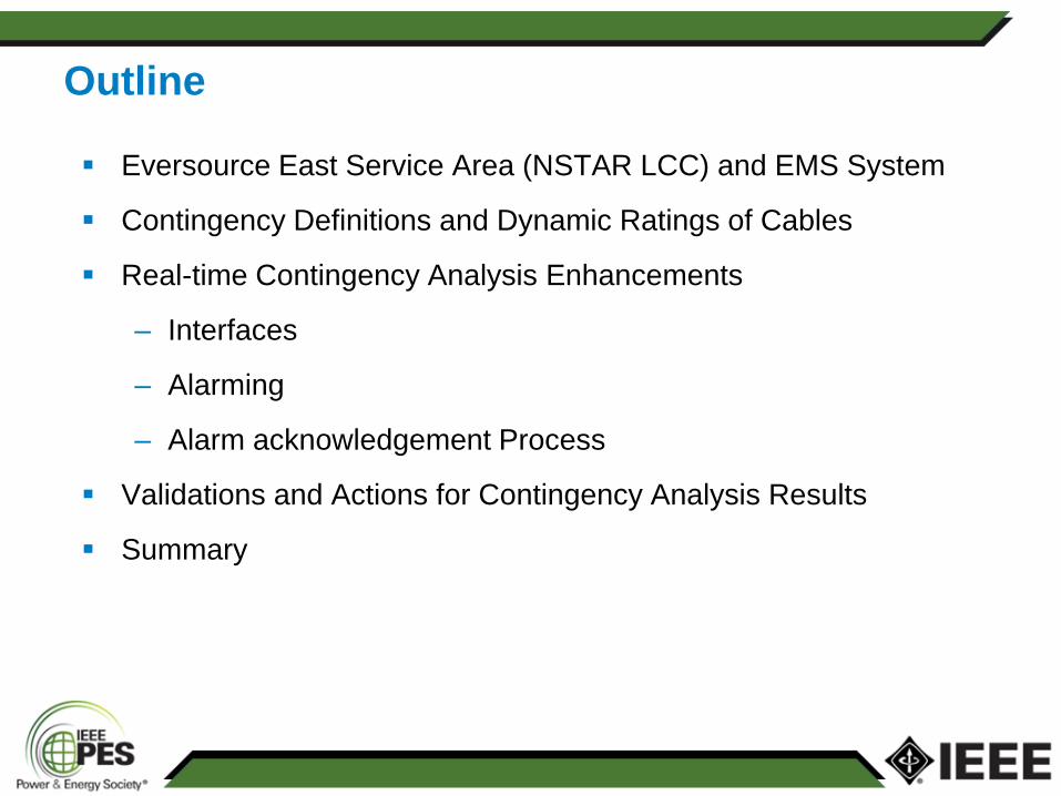
New England’s largest energy
delivery company.
More than 3.6 million electric
and natural gas customers in
3 states: Connecticut,
Massachusetts and New
Hampshire.
Eversource Energy New Hampshire
Massachusetts
Connecticut Rohde
Island
Vermont
Maine
Electric service territory includes
500 towns and covers 13,217
square miles.
3 Transmission Control Centers
and 3 Backups. 5 Distribution
Control Centers: 1 in NH, 1 in CT, 3
in MA.
New Hampshire
Massachusetts
Connecticut
Eversource East
NSTAR LCC: majority of
Greater Boston area,
Southeastern MA area.
20% of ISO-NE load.
Eversource Eastern MA
Eversource Energy
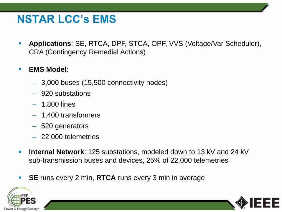
NSTAR LCC’s EMS
Applications: SE, RTCA, DPF, STCA, OPF, VVS (Voltage/Var Scheduler),
CRA (Contingency Remedial Actions)
EMS Model:
– 3,000 buses (15,500 connectivity nodes)
– 920 substations
– 1,800 lines
– 1,400 transformers
– 520 generators
– 22,000 telemetries
Internal Network: 125 substations, modeled down to 13 kV and 24 kV
sub-transmission buses and devices, 25% of 22,000 telemetries
SE runs every 2 min, RTCA runs every 3 min in average
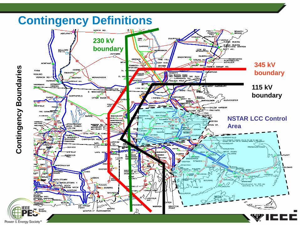
Contingency Definitions
345 kV
boundary
115 kV
boundary
230 kV
boundary
NSTAR LCC Control
Area
Co
nti
ng
en
cy B
ou
nd
ari
es
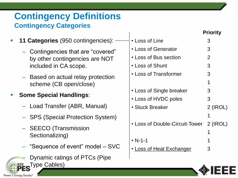
Contingency Definitions Contingency Categories
Priority
• Loss of Line 3
• Loss of Generator 3
• Loss of Bus section 2
• Loss of Shunt 3
• Loss of Transformer 3
1
• Loss of Single breaker 3
• Loss of HVDC poles 3
• Stuck Breaker 2 (IROL)
1
• Loss of Double-Circuit-Tower 2 (IROL)
1
• N-1-1 1
• Loss of Heat Exchanger 3
11 Categories (950 contingencies):
– Contingencies that are “covered”
by other contingencies are NOT
included in CA scope.
– Based on actual relay protection
scheme (CB open/close)
Some Special Handlings:
– Load Transfer (ABR, Manual)
– SPS (Special Protection System)
– SEECO (Transmission
Sectionalizing)
– “Sequence of event” model – SVC
– Dynamic ratings of PTCs (Pipe
Type Cables)
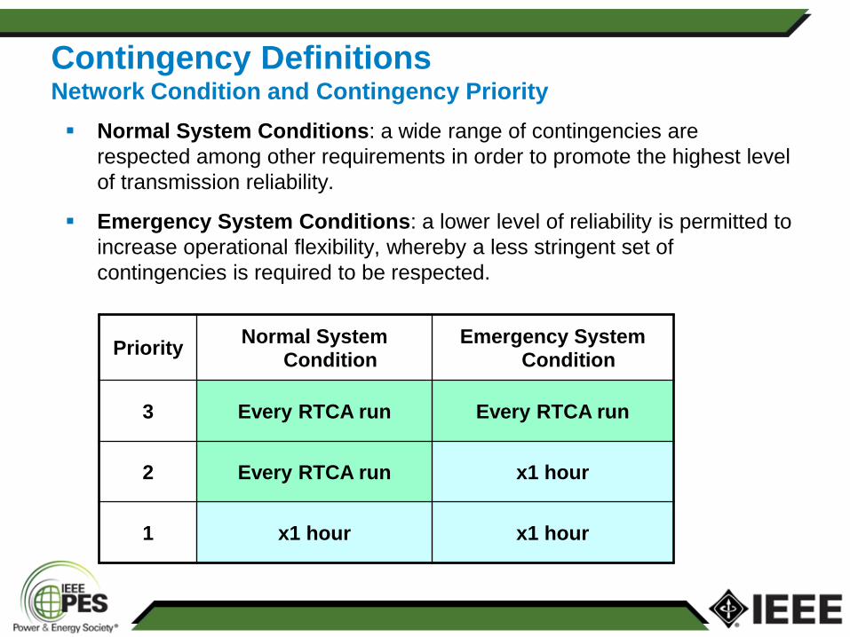
Contingency Definitions Network Condition and Contingency Priority
Priority Normal System
Condition Emergency System
Condition
3 Every RTCA run Every RTCA run
2 Every RTCA run x1 hour
1 x1 hour x1 hour
Normal System Conditions: a wide range of contingencies are
respected among other requirements in order to promote the highest level
of transmission reliability.
Emergency System Conditions: a lower level of reliability is permitted to
increase operational flexibility, whereby a less stringent set of
contingencies is required to be respected.
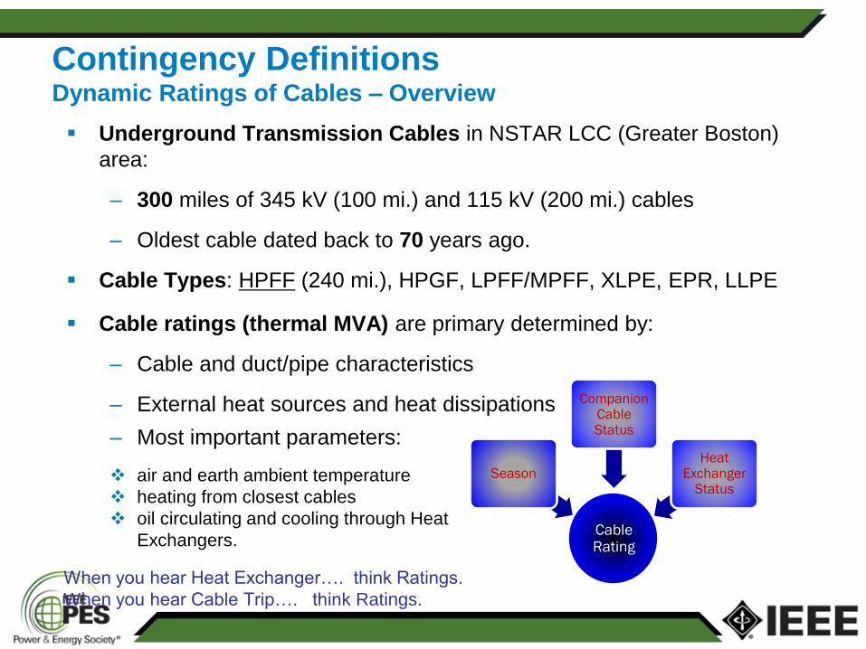
Contingency Definitions Dynamic Ratings of Cables – Overview
Underground Transmission Cables in NSTAR LCC (Greater Boston)
area:
– 300 miles of 345 kV (100 mi.) and 115 kV (200 mi.) cables
– Oldest cable dated back to 70 years ago.
Cable Types: HPFF (240 mi.), HPGF, LPFF/MPFF, XLPE, EPR, LLPE
Cable Rating
Season
Companion Cable Status
Heat Exchanger
Status
When you hear Heat Exchanger…. think Ratings.
When you hear Cable Trip…. think Ratings.
– Most important parameters:
air and earth ambient temperature
heating from closest cables
oil circulating and cooling through Heat
Exchangers.
Cable ratings (thermal MVA) are primary determined by:
– Cable and duct/pipe characteristics
– External heat sources and heat dissipations
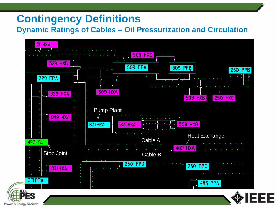
Contingency Definitions Dynamic Ratings of Cables – Oil Pressurization and Circulation
Cable A
Cable B
Heat Exchanger
Pump Plant
Stop Joint
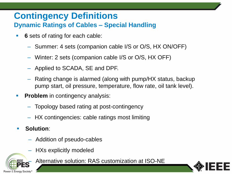
Contingency Definitions Dynamic Ratings of Cables – Special Handling
6 sets of rating for each cable:
– Summer: 4 sets (companion cable I/S or O/S, HX ON/OFF)
– Winter: 2 sets (companion cable I/S or O/S, HX OFF)
– Applied to SCADA, SE and DPF.
– Rating change is alarmed (along with pump/HX status, backup
pump start, oil pressure, temperature, flow rate, oil tank level).
Problem in contingency analysis:
– Topology based rating at post-contingency
– HX contingencies: cable ratings most limiting
Solution:
– Addition of pseudo-cables
– HXs explicitly modeled
– Alternative solution: RAS customization at ISO-NE
HX B HX A
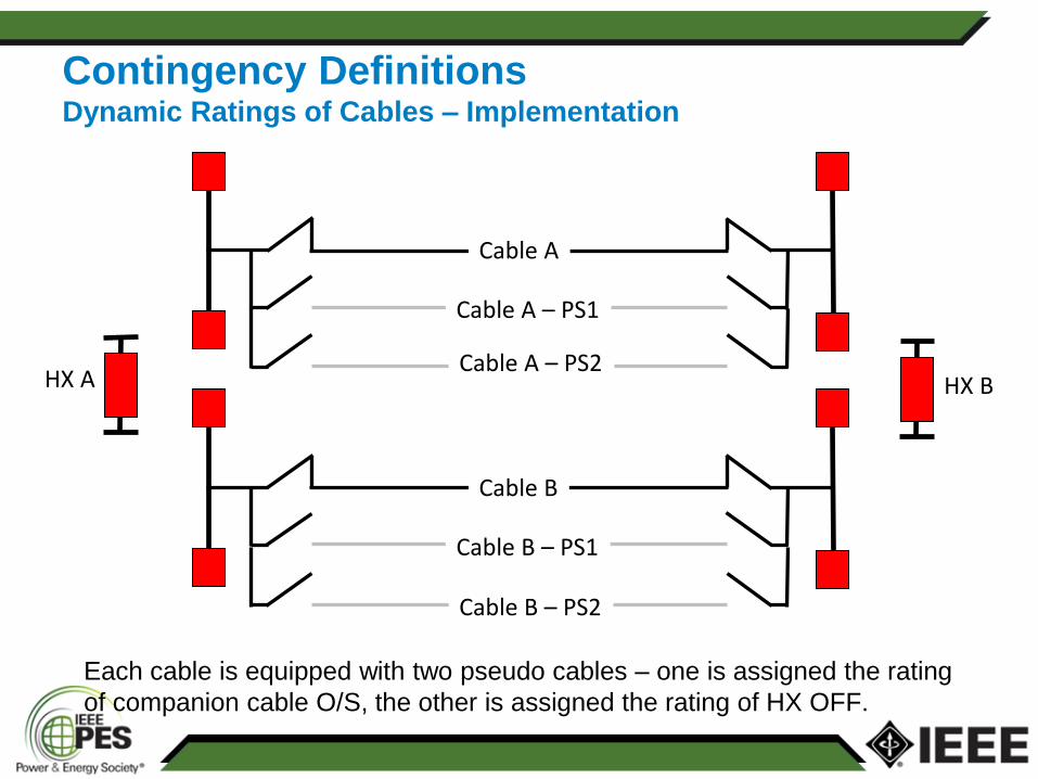
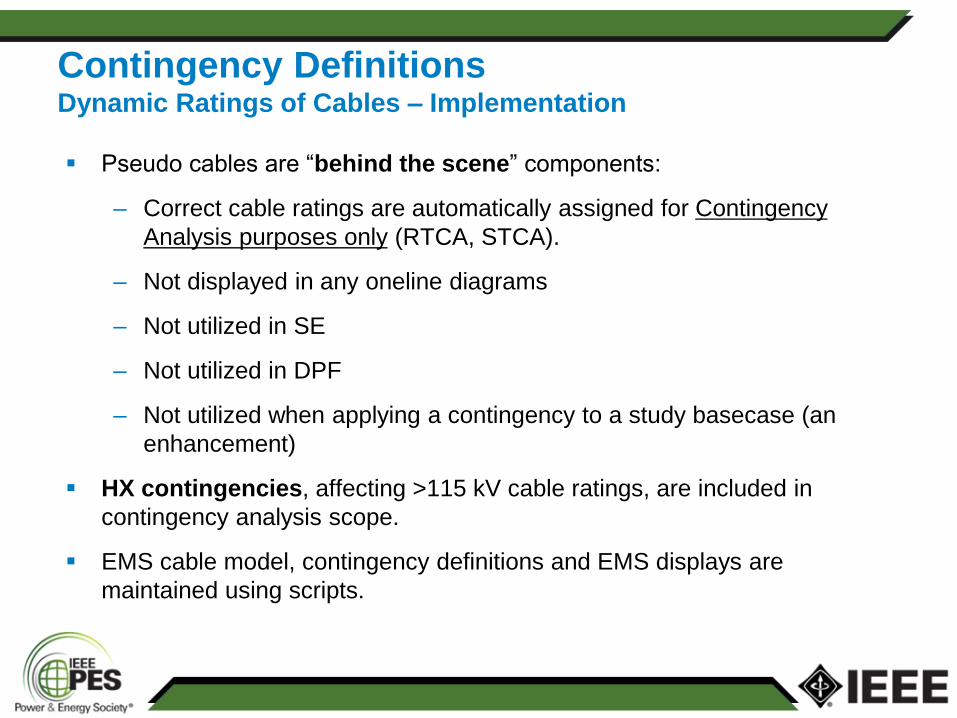
Contingency Definitions Dynamic Ratings of Cables – Implementation
Each cable is equipped with two pseudo cables – one is assigned the rating
of companion cable O/S, the other is assigned the rating of HX OFF.
Cable A
Cable A – PS1
Cable B
Cable B – PS1
Cable A – PS2
Cable B – PS2
HX B HX A
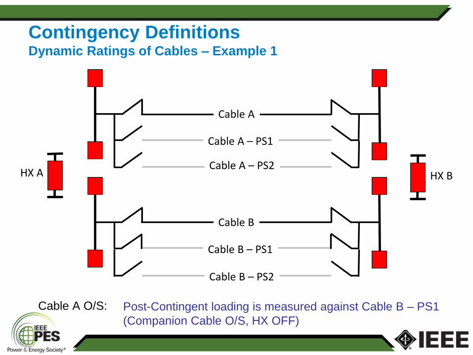
Contingency Definitions Dynamic Ratings of Cables – Example 1
Cable A O/S:
Cable A
Cable A – PS1
Cable B
Cable B – PS1
Cable A – PS2
Cable B – PS2
Post-Contingent loading is measured against Cable B – PS1
(Companion Cable O/S, HX OFF)
HX B HX A
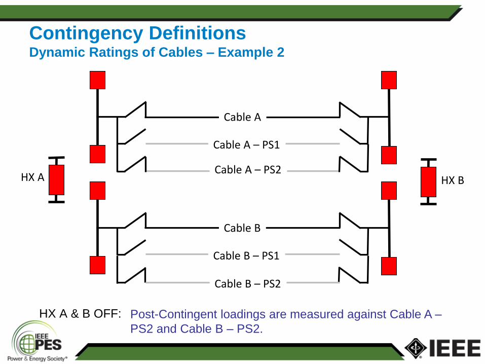
Contingency Definitions Dynamic Ratings of Cables – Example 2
HX A & B OFF:
Cable A
Cable A – PS1
Cable B
Cable B – PS1
Cable A – PS2
Cable B – PS2
Post-Contingent loadings are measured against Cable A –
PS2 and Cable B – PS2.
Contingency Definitions Dynamic Ratings of Cables – Implementation
Pseudo cables are “behind the scene” components:
– Correct cable ratings are automatically assigned for Contingency
Analysis purposes only (RTCA, STCA).
– Not displayed in any oneline diagrams
– Not utilized in SE
– Not utilized in DPF
– Not utilized when applying a contingency to a study basecase (an
enhancement)
HX contingencies, affecting >115 kV cable ratings, are included in
contingency analysis scope.
EMS cable model, contingency definitions and EMS displays are
maintained using scripts.
Real-Time Contingency Analysis
Why RTCA:
– Situational awareness (N-x) and operational reliability
– Pre- and Post-contingency action plans are to be developed
– Pre-contingency actions need to be executed
– Pre- and Post- contingent actions must be completed in a timely
fashion
NERC TOP-001: Each Transmission Operator shall initiate its Operating
Plan to mitigate a SOL exceedance identified as part of its Real-time
monitoring or Real-time Assessment.
The Operating Plan provides the times within which these actions must
be taken (pre & post-contingent).
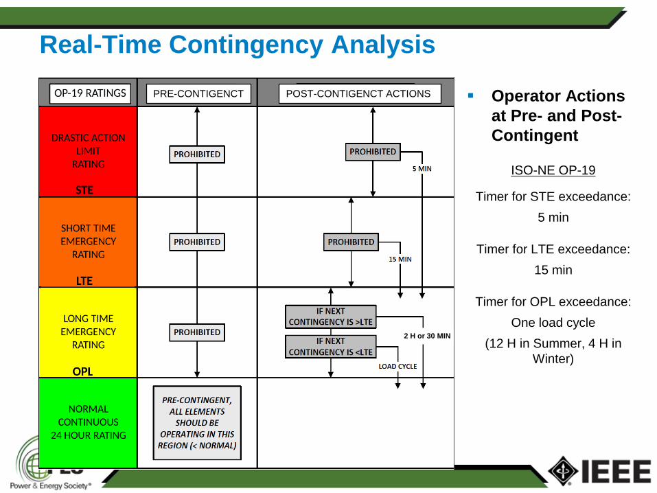
Real-Time Contingency Analysis
Operator Actions
at Pre- and Post-
Contingent
POST-CONTIGENCT ACTIONS PRE-CONTIGENCT
ISO-NE OP-19
Timer for STE exceedance:
5 min
Timer for LTE exceedance:
15 min
Timer for OPL exceedance:
One load cycle
(12 H in Summer, 4 H in
Winter)
2 H or 30 MIN
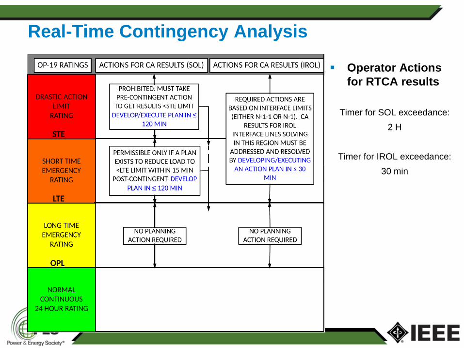
Real-Time Contingency Analysis
Operator Actions
for RTCA results
Timer for SOL exceedance:
2 H
Timer for IROL exceedance:
30 min
Real-Time Contingency Analysis
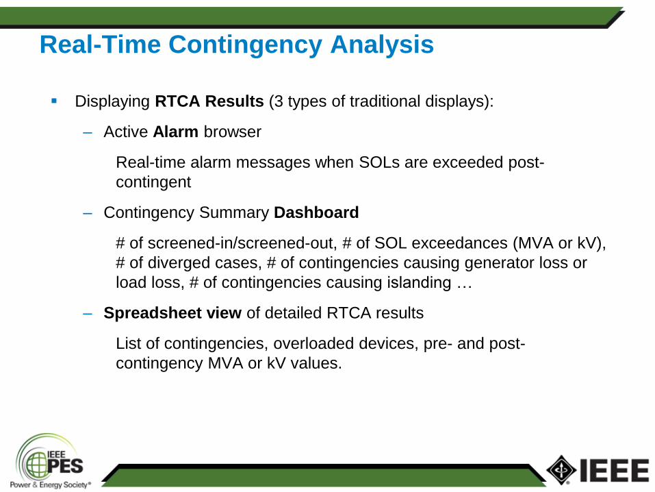
Displaying RTCA Results (3 types of traditional displays):
– Active Alarm browser
Real-time alarm messages when SOLs are exceeded post-
contingent
– Contingency Summary Dashboard
# of screened-in/screened-out, # of SOL exceedances (MVA or kV),
# of diverged cases, # of contingencies causing generator loss or
load loss, # of contingencies causing islanding …
– Spreadsheet view of detailed RTCA results
List of contingencies, overloaded devices, pre- and post-
contingency MVA or kV values.
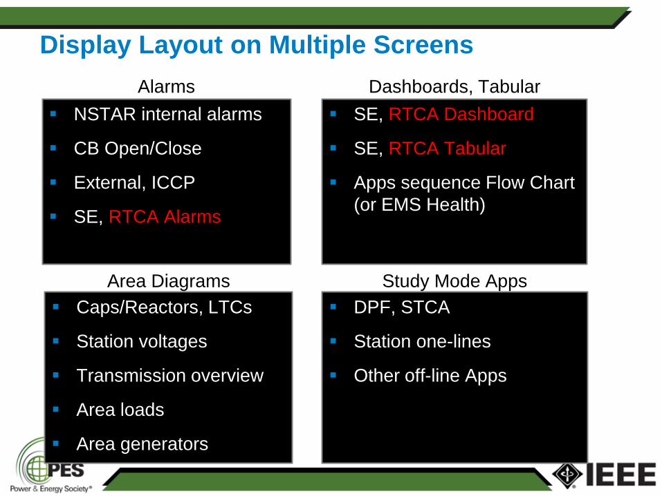
NSTAR internal alarms
CB Open/Close
External, ICCP
SE, RTCA Alarms
Display Layout on Multiple Screens
Alarms
SE, RTCA Dashboard
SE, RTCA Tabular
Apps sequence Flow Chart
(or EMS Health)
Caps/Reactors, LTCs
Station voltages
Transmission overview
Area loads
Area generators
DPF, STCA
Station one-lines
Other off-line Apps
Dashboards, Tabular
Area Diagrams Study Mode Apps
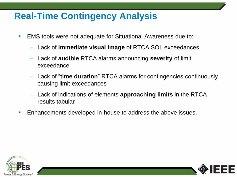
EMS tools were not adequate for Situational Awareness due to:
– Lack of immediate visual image of RTCA SOL exceedances
– Lack of audible RTCA alarms announcing severity of limit
exceedance
– Lack of “time duration” RTCA alarms for contingencies continuously
causing limit exceedances
– Lack of indications of elements approaching limits in the RTCA
results tabular
Enhancements developed in-house to address the above issues.
Real-Time Contingency Analysis
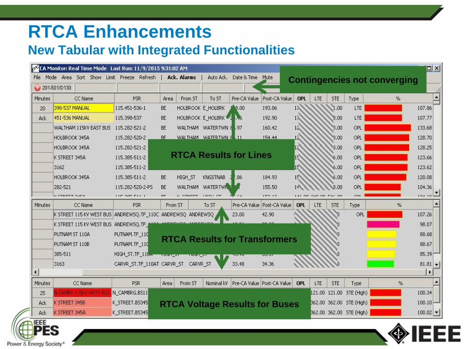
RTCA Enhancements New Tabular with Integrated Functionalities
RTCA Results for Lines
RTCA Voltage Results for Buses
Contingencies not converging
RTCA Results for Transformers
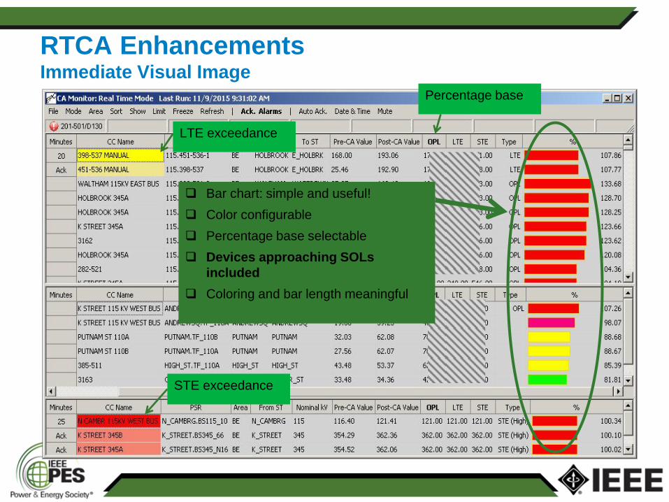
RTCA Enhancements Immediate Visual Image
Percentage base
STE exceedance
LTE exceedance
Bar chart: simple and useful!
Color configurable
Percentage base selectable
Devices approaching SOLs
included
Coloring and bar length meaningful
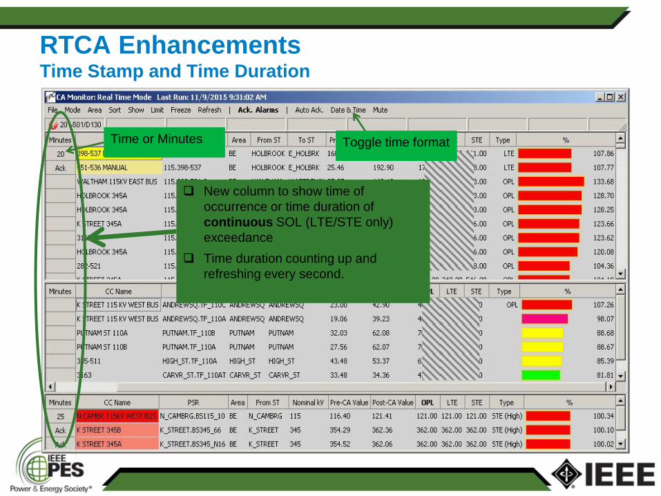
RTCA Enhancements Time Stamp and Time Duration
Time or Minutes Toggle time format
New column to show time of
occurrence or time duration of
continuous SOL (LTE/STE only)
exceedance
Time duration counting up and
refreshing every second.
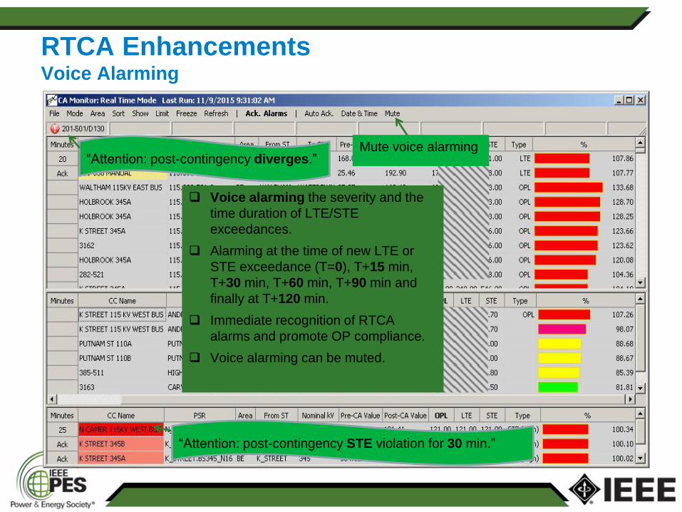
RTCA Enhancements Voice Alarming
“Attention: post-contingency STE violation for 30 min.”
“Attention: post-contingency diverges.” Mute voice alarming
Voice alarming the severity and the
time duration of LTE/STE
exceedances.
Alarming at the time of new LTE or
STE exceedance (T=0), T+15 min,
T+30 min, T+60 min, T+90 min and
finally at T+120 min.
Immediate recognition of RTCA
alarms and promote OP compliance.
Voice alarming can be muted.
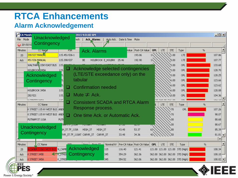
RTCA Enhancements Alarm Acknowledgement
Ack. Alarms
Acknowledged
Contingency
Acknowledged
Contingency
Unacknowledged
Contingency
Unacknowledged
Contingency
Acknowledge selected contingencies
(LTE/STE exceedance only) on the
tabular
Confirmation needed
Mute Ack.
Consistent SCADA and RTCA Alarm
Response process.
One time Ack. or Automatic Ack.
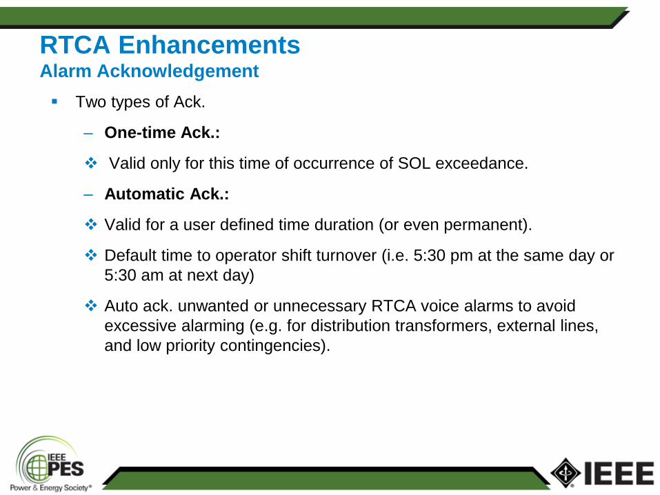
RTCA Enhancements Alarm Acknowledgement
Two types of Ack.
– One-time Ack.:
Valid only for this time of occurrence of SOL exceedance.
– Automatic Ack.:
Valid for a user defined time duration (or even permanent).
Default time to operator shift turnover (i.e. 5:30 pm at the same day or
5:30 am at next day)
Auto ack. unwanted or unnecessary RTCA voice alarms to avoid
excessive alarming (e.g. for distribution transformers, external lines,
and low priority contingencies).
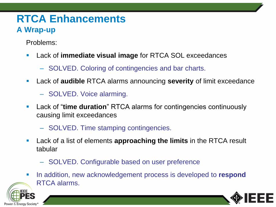
Problems:
Lack of immediate visual image for RTCA SOL exceedances
– SOLVED. Coloring of contingencies and bar charts.
Lack of audible RTCA alarms announcing severity of limit exceedance
– SOLVED. Voice alarming.
Lack of “time duration” RTCA alarms for contingencies continuously
causing limit exceedances
– SOLVED. Time stamping contingencies.
Lack of a list of elements approaching the limits in the RTCA result
tabular
– SOLVED. Configurable based on user preference
In addition, new acknowledgement process is developed to respond
RTCA alarms.
RTCA Enhancements A Wrap-up
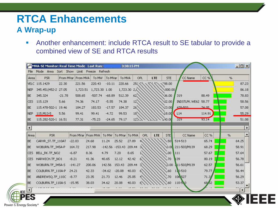
RTCA Enhancements A Wrap-up
Another enhancement: include RTCA result to SE tabular to provide a
combined view of SE and RTCA results
Identify SOL, IROL and time allowed based on OP/OG
– Time allowed in current state (120 min or 30 min)
– Time within which an action plan must be developed and pre-
contingency action must be taken
Verify real-time SE solution
– Large mismatch, incorrect or failed telemetries, wrong limits, rejected
measurements, low voltages.
Validate CA solution in study mode
– Assume the accuracy of CA adheres to the accuracy of SE
– Confidence level: 5% for MVA, 1% for kV
Validation and Actions for RTCA Results
Communicate with ISO-NE and neighboring LCC
– Discrepancies not uncommon
Improper modeling incl. regulations, sub-transmission model, circuit
parameters or ratings. Software issues.
– Respect most conservative solution
Develop mitigation plan
– Move PAR taps, switch Caps/Rs & circuits, apply enhanced limits,
request unit Mvar adjustment, seek unit re-dispatch by ISO, shed
loads.
Execute the plan as applicable
– Within the required time frame upon validation of RTCA
Log event in TOA (Transmission Outage Application) DB. Phone
communications are recorded.
Acknowledge related alarms incl. voice alarms
Validation and Actions for RTCA Results
Dynamic ratings of NSTAR cables are implemented by special
handling of PTCs and HXs in EMS model and RTCA.
Important enhancements on RTCA application,
– Colored bar charts
– Contingency coloring
– Limit approaching monitor
– Voice alarming
– Alarm acknowledgement and auto acknowledgement,
– All developed to promote better alarming and situational
awareness.
These improvements provide NSTAR’s system operators with much
more adequate tools for managing and responding to RTCA results
in compliance with mandatory OP and NERC Standards.
Summary
Thank you for your attention!
Q & A