Embed Size (px)
Citation preview

R E S E A R C H R E P O R T
Innovative Technologies for Lifetime Extension of an Aging Inventory of Vulnerable Bridges
Andrew GastineauSteven Wojtkiewicz
Arturo Schultz
Department of Civil EngineeringUniversity of Minnesota
CTS 11-27

Technical Report Documentation Page 1. Report No. 2. 3. Recipients Accession No. CTS 11-27 4. Title and Subtitle 5. Report Date
Innovative Technologies for Lifetime Extension of an Aging Inventory of Vulnerable Bridges
December 2011 6.
7. Author(s) 8. Performing Organization Report No. Andrew Gastineau, Steven Wojtkiewicz, Arturo Schultz 9. Performing Organization Name and Address 10. Project/Task/Work Unit No. Department of Civil Engineering University of Minnesota 500 Pillsbury Dr., SE Minneapolis, MN 55455
CTS Project #2011081 11. Contract (C) or Grant (G) No.
12. Sponsoring Organization Name and Address 13. Type of Report and Period Covered Center for Transportation Studies University of Minnesota 200 Transportation and Safety Building 511 Washington Ave. SE Minneapolis, MN 55455
Final Report 14. Sponsoring Agency Code
15. Supplementary Notes http://www.cts.umn.edu/Publications/ResearchReports/ 16. Abstract (Limit: 250 words)
This report refines a response modification framework, previously developed by the authors, which combines technological developments in the fields of control systems, health monitoring, and bridge engineering to increase bridge safety. To enhance the modification framework, the numerical bridge model is refined and additional modification apparatuses are added to the numerical model to further develop and confirm the advantages of the response modification approach. A parameter study of the modification apparatus characteristics is carried out to optimize member sizes and modification device characteristics. Finally, a frequency response analysis is carried out to investigate the use of a semi-active system within the scope of the response modification framework.
17. Document Analysis/Descriptors Equilibrium methods (Structural analysis), Structural response modification, Structural control, Structural stability (Mathematics), Dynamics, Bridge dynamics, Bridge life extension, Bridge design, Bridge management systems, Fatigue
18. Availability Statement
tests
No restrictions. Document available from: National Technical Information Services, Alexandria, Virginia 22312
19. Security Class (this report) 20. Security Class (this page) 21. No. of Pages 22. Price Unclassified Unclassified 28

Innovative Technologies for Lifetime Extension of an Aging Inventory of Vulnerable Bridges
Final Report
Prepared by:
Andrew Gastineau Steven Wojtkiewicz
Arturo Schultz
Department of Civil Engineering University of Minnesota
December 2011
Published by:
Center for Transportation Studies University of Minnesota
200 Transportation and Safety Building 511 Washington Avenue SE
Minneapolis, Minnesota 55455
This report represents the results of research conducted by the authors and does not necessarily represent the views or policies of the University of Minnesota.
The authors and the University of Minnesota do not endorse products or manufacturers. Any trade or manufacturers’ names that may appear herein do so solely because they are considered essential to this report.

Acknowledgment
The authors would like to extend their appreciation to the Center for Transportation Studies at the University of Minnesota for supporting this work.

Table of Contents
Chapter 1. Introduction ............................................................................................................... 1
1.1 Cedar Avenue Bridge with Response Modification Apparatus ....................................... 2
1.2 Bridge Model .................................................................................................................... 3
Chapter 2. Multiple Passive Modification Devices .................................................................... 5
Chapter 3. Optimization of the Properties the Response Modification Apparatuses ............... 11
Chapter 4. Extension of the Modification Framework to Include Semi-Active Devices ......... 15
4.1 Frequency Response Analysis of a Simple Beam .......................................................... 15
4.2 Frequency Response Analysis of a Cedar Avenue Bridge ............................................. 16
Chapter 5. Conclusions ............................................................................................................. 19
References ..................................................................................................................................... 21

List of Tables
Table 1 Deflection ranges for the Cedar Avenue Bridge model not including the bridge deck with 2 apparatuses ................................................................................................................................... 7Table 2 Moment ranges for the Cedar Avenue Bridge model ........................................................ 7Table 3 Remaining safe life for the Cedar Avenue Bridge with varying response modification apparatuses ...................................................................................................................................... 8Table 4 Cedar Avenue Bridge damping criteria ........................................................................... 11Table 5 Apparatus member sizes, lengths, and stiffnesses ........................................................... 12Table 6 Moment ranges at L3 connection for long apparatuses without damping ....................... 12Table 7 Moment ranges at L3 connection for long apparatuses with damping ............................ 12Table 8 Moment ranges at L3 connection for medium apparatuses without damping ................. 12Table 9 Moment ranges at L3 connection for medium apparatuses with damping ...................... 13Table 10 Moment ranges at L3 connection for short apparatuses without damping .................... 13Table 11 Moment ranges at L3 connection for short apparatuses with damping ......................... 13Table 12 Moment ranges at L3 connection for various device parameters .................................. 13Table 13 Comparison of cost per percent reduction for different apparatus characteristics ........ 13Table 14 Fatigue truck loading frequencies .................................................................................. 17Table 15 Fatigue truck loading speeds with increased deflections ............................................... 18
List of Figures
Figure 1 Tied arch Cedar Avenue Bridge ....................................................................................... 2 Figure 2 Response modification apparatus on a simple beam ........................................................ 2 Figure 3 Cedar Avenue Bridge moment envelope .......................................................................... 3 Figure 4 Cedar Avenue Bridge model with modification apparatuses on one end ........................ 3 Figure 5 Deck shearing mode that was eliminated in new modeling ............................................. 4 Figure 6 Cedar Avenue Bridge model with multiple response modification apparatuses .............. 6 Figure 7 Moment envelope for Cedar Avenue Bridge with multiple apparatuses ......................... 8 Figure 8 Moment envelope for Cedar Avenue Bridge with a single pair of apparatuses ............... 8 Figure 9 Beam response of beam loaded at the center with an oscillating point load .................. 16 Figure 10 Bridge frequency response for deflection at the L3 joint and 72 kip load at midspan for the Cedar Avenue Bridge numerical model without the deck ...................................................... 17

Executive Summary
This report aims to refine a response modification framework that effectively combines technological developments in the fields of control systems, health monitoring, and bridge engineering to achieve enhanced bridge safety. Recently, the investigators have demonstrated the potential of the framework by examining the benefits of augmenting an existing bridge with a simple passive external spring/damper device (as a supplemental source of both stiffness and damping) attached to the bridge using a simple mounting mechanism (scissor jack) to amplify the motion generated by the flexural deformation of the bridge members with the design goal of reducing moment range, i.e. stress ranges, seen in the girders of the bridge [1]. By showing that moment ranges can be reduced at specific joints, the framework can similarly be used on fatigue vulnerable connections to effectively reduce moment ranges to increase safe bridge life. The framework is refined and extended through the use of multiple apparatuses, model refinement, and a parameter study concerning apparatus characteristics, and a frequency response analysis of the modified structural system. Before investigating the use of multiple modification apparatuses, a refined bridge model is developed and implemented in the finite element software SAP2000. The bridge deck is added to the original model and the elimination of non-physical mode shapes present in the dynamic response is performed by constraining particular degrees of freedom. The initial study [1] showed promising results and the response modification approach is extended here through the use of multiple modification apparatuses to further minimize bridge vulnerabilities. Because of the symmetric nature of the bridge structure, response modification apparatuses at similar connections should be beneficial. Through numerical simulations, it is shown that multiple apparatuses further decrease overall deflections at the connections under consideration and also increase the fatigue life by decreasing the moment ranges of the connections where the additional apparatuses are placed. In addition to the use of multiple apparatuses, the optimization of the geometry, materials, and member sizes of the response modification apparatus is investigated. In previous analyses, the members of the modification apparatus were assumed to be rigid for comparison to analytical results, but in reality will be able to deform. Through numerical analyses, it is shown that the sizes of the apparatus members have a significant impact on the apparatus performance and need to be considered when applying the response modification approach. Lastly, a frequency response analysis is carried out to motivate the possible use of semi-active devices with control systems to increase performance over the passive devices. The results of a simple beam study show that the ability to change the natural frequencies of the structure through a change in stiffness of the device would be of interest. A frequency response study using a representative bridge model is carried out and shows that magnification of the bridge response can occur at certain loading frequencies, and the ability to shift these amplified response peaks through semi-active control would be advantageous.

1
Chapter 1. Introduction
Many of the bridges in Minnesota and throughout the United States are being used beyond their initial design intentions, classified as structurally deficient, and are in need of rehabilitation or replacement. According to Minnesota Department of Transportation (Mn/DOT) records, as of July 2010, 270 highway bridges in Minnesota are classified as structurally deficient or obsolete. Of those, 99 are structurally deficient signifying that one or more members or connections of the bridge should be repaired or replaced in the near future. The majority of these bridges were built in the 1950s and 60s and are at or near the end of their intended design life. This situation prompts one to pose the following questions: (1) How can bridge owners extend the life of these bridges while funds are allocated for bridge replacement? (2) What options are both safe and affordable? A large portion of bridges that are structurally deficient are steel structures which have details that are prone to fatigue damage, and in some cases prestressed concrete structures with details that can deteriorate under repeated loading after cracking. Due to the fiscal constraints of many bridge owners, the replacement of these bridges is cost prohibitive and it will be appealing, if not necessary, to extend the life of these bridges in a safe and cost effective manner. The service life of these fatigue prone details is governed by the size and number of cyclic stress ranges experienced by the detail. As a result, if the stress ranges encountered by the detail can be reduced, the safe extension of bridge life can be accomplished. Currently, the safety of bridges from repetitive loading and overloading is accomplished through a combination of activities including scheduled inspections, load rating calculations, and bridge monitoring. However, the latter is only done in special cases due to the cost of the equipment and the skilled personnel, and load rating calculations require many simplifying assumptions and extensive detailed computations. Thus, the safety of most bridges rests in the hands of the inspectors whose task is often limited to visual inspections. Given the size of the population of aging bridges in Minnesota and throughout the United States, automated and reliable methods are needed to enhance the safety and service life of existing bridges. This report aims to refine a response modification framework which effectively combines technological developments in the fields of control systems, health monitoring, and bridge engineering to achieve enhanced bridge safety. Recently, the investigators have demonstrated the potential of the framework by examining the benefits of augmenting an existing bridge in the Minnesota inventory, the Cedar Avenue Bridge, with a simple passive external spring/damper device (as a supplemental source of both stiffness and damping) attached to the bridge using a simple mounting mechanism (scissor jack) to amplify the motion generated by the flexural deformation of the bridge members with the design goal of reducing moment range, i.e. stress ranges, seen in the girders of the bridge [1]. Although the bridge in the initial study has a long history of in-service performance with no observed issues, the initial study showed promising results for stress range reductions and in this report the response modification approach is extended through the use of multiple modification apparatuses to further minimize bridge vulnerabilities. Additionally, the optimization of the geometry, materials, and member sizes of the response modification apparatus is investigated. Lastly, a frequency response analysis is carried out to motivate the possible use of semi-active devices with control systems to increase performance over the passive devices. The results of the initial study are briefly summarized in the next section before the use of multiple apparatuses is investigated.

2
1.1 Cedar Avenue Bridge with Response Modification Apparatus
The Cedar Avenue Bridge is a steel tied arch bridge, as shown in Figure 1, which means that it is fracture critical. Due to the non-redundant nature of a fracture critical bridge, fatigue failure of the tie box girders or their connections could be catastrophic and is of concern. The bridge has not shown evidence of distress over its 20+ years of service and is expected to continue to perform in that manner, and it is used here simply to illustrate the potentially dramatic impact of the research methodology. Previous research has shown that stress concentrations exist at the joints where the hangers and floor beams attach to the tie box girder [5]. Application of response modification methodology on the Cedar Avenue Bridge using a set of response modification apparatuses at the left (north) end of the bridge reduces live load moment ranges in a 3D finite element model of the bridge using the SAP2000 structural analysis software. By reducing the live load moment range, bridge life can be safely extended in structures with a finite fatigue life because the latter is inversely proportional to the cube of the stress range [4]; even small reductions in moment ranges can have a large effect on fatigue life. Assuming the connections in the Cedar Avenue Bridge have a finite fatigue life due to their stress concentrations, the combination of the passive spring/damper with the scissor jack mounting device reduced vertical deflections, moments and stress levels in the box tie girders by as much as one third (i.e., 33%). Using the fatigue life estimation described in the Manual for Bridge Evaluation [4] and assuming an initial fatigue design life of 50 years, these reductions translate into fatigue life extensions of as much as 60 years, thus giving bridge owners ample time to allocate funds to replace a bridge that has reached its design life limit.
Figure 1 Tied arch Cedar Avenue Bridge
Figure 2 Response modification apparatus on a simple beam

3
The initial study utilized a response modification approach which used a simple device providing supplemental stiffness and damping and a mechanical amplification device known as the scissor jack to provide counter moments to reduce the moment range across potentially problematic details (Figure 2). The moment diagram (Figure 3) shows that the highest moment range, i.e. the most potentially vulnerable connection, occurs at the third joint from the end, L3. The study attached the modification apparatuses on one end of the bridge (Figure 4) and reduced moment ranges by over 30 percent. However, it is clear that due to the symmetric nature of the bridge, reduction in the joint on the opposite end also needs to take place so that the structure is not limited in service life by the other connection. Therefore, 4 apparatuses placed in two pairs on either end of the bridge would seem to be a natural extension of the previous work which may also further reduce deflections and moment ranges encountered by the bridge.
Figure 3 Cedar Avenue Bridge moment envelope
Figure 4 Cedar Avenue Bridge model with modification apparatuses on one end
1.2 Bridge Model
Before investigating the use of multiple modification apparatuses, a refined bridge model needed to be developed and implemented in the finite element software SAP2000 and will now be described. The model used throughout this paper is a refinement of the Cedar Avenue Bridge numerical model originally described by Gastineau et al. [1]. The original model only included the steel elements of the bridge superstructure with only planar degrees of freedom so the bridge deck and full spatial analyses was added as discussed by Gastineau et al. [2] to assure that the amount of moment reduction seen at the joint under consideration was not negatively impacted due to the added stiffness and load redistribution from the deck. Additionally, two more modification apparatuses were added to the model used by Gastineau et al. [2] for a total of four modification apparatuses, one set at each potentially vulnerable joint. The most recent model used in the optimization section adds additional model constraints to eliminate mode shapes that
Mmax at L3
4
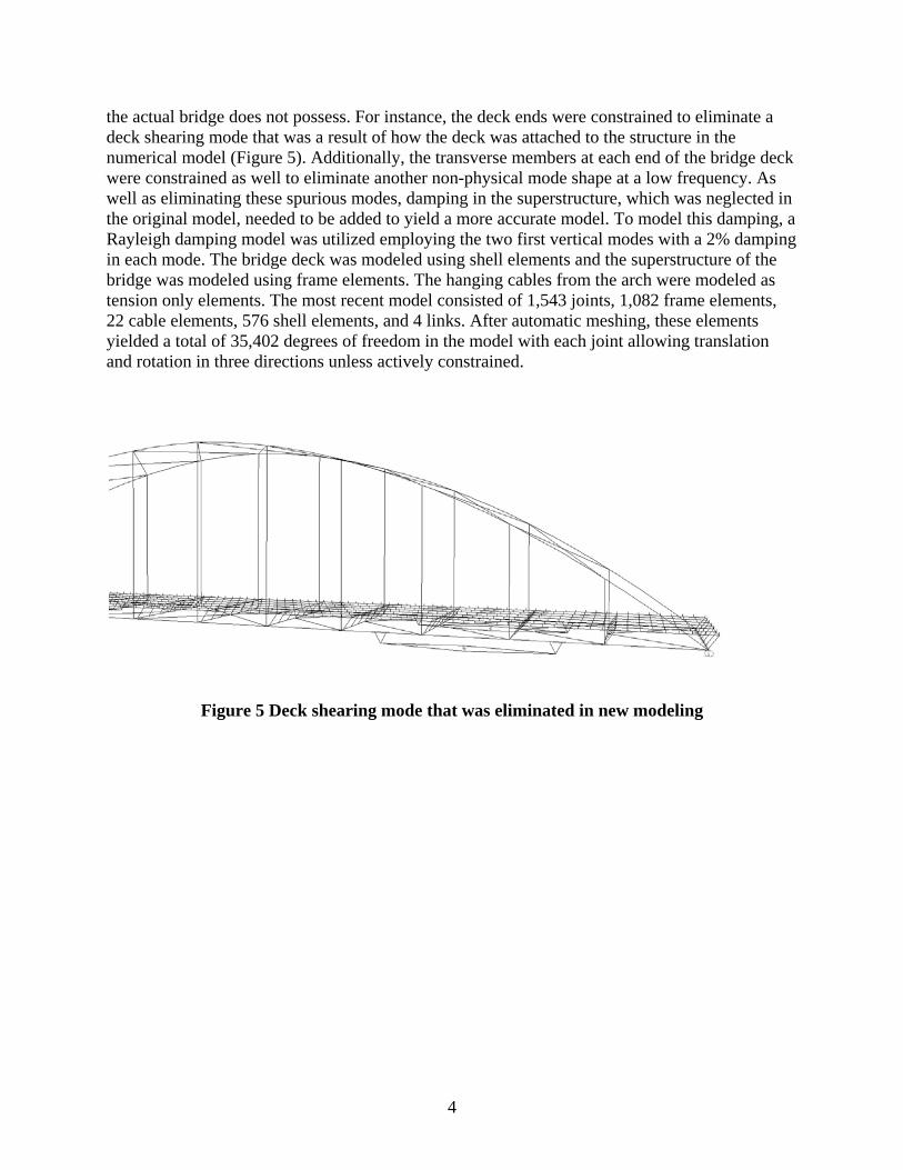
the actual bridge does not possess. For instance, the deck ends were constrained to eliminate a deck shearing mode that was a result of how the deck was attached to the structure in the numerical model (Figure 5). Additionally, the transverse members at each end of the bridge deck were constrained as well to eliminate another non-physical mode shape at a low frequency. As well as eliminating these spurious modes, damping in the superstructure, which was neglected in the original model, needed to be added to yield a more accurate model. To model this damping, a Rayleigh damping model was utilized employing the two first vertical modes with a 2% damping in each mode. The bridge deck was modeled using shell elements and the superstructure of the bridge was modeled using frame elements. The hanging cables from the arch were modeled as tension only elements. The most recent model consisted of 1,543 joints, 1,082 frame elements, 22 cable elements, 576 shell elements, and 4 links. After automatic meshing, these elements yielded a total of 35,402 degrees of freedom in the model with each joint allowing translation and rotation in three directions unless actively constrained.
Figure 5 Deck shearing mode that was eliminated in new modeling

5
Chapter 2. Multiple Passive Modification Devices
While the use of a single modification device shows great promise as evidenced by the aforementioned example fully described by Gastineau et al. [1], it is hypothesized that the judicious use of multiple response modification devices will only increase the reduction of bridge response due to typical, service loads and thus even further extend the lifetime of the bridge. This section will investigate the application of multiple passive spring/damper combinations on the Cedar Avenue Bridge model using the results that were published by Gastineau et al. [2] and will compare these to the modified spatial analysis results from the model used by Gastineau et al. [1] shown in Tables 1 and 2. Numerical analyses were completed using the refined model in the finite element program SAP2000 and the moment envelope for the bridge structure with multiple response modification apparatuses with different geometric configurations was calculated. For comparison, the moment ranges were also computed for an approach similar to that used by Patten et al. [6] which used a response modification apparatus with a response modification device but no mechanical amplifier. The efficacy of the addition of multiple response modification apparatuses, consisting of the scissor jack mechanical amplifier and a response modification device, to reduce the stress ranges experienced by a detail for extending the fatigue life of the bridge is demonstrated in the results. As seen in Table 1, the deflections at the joint under consideration were reduced by 12 to 28 percent depending on the length and magnification factor of the response modification apparatus. In addition, the response modification apparatus with the amplifier clearly outperforms a response modification apparatus alone which has length but no magnification value, m. It is interesting to note that, for overall deflection range reduction, a longer response modification apparatus is more beneficial than increasing the magnification factor. Also, comparing the deflections in Table 1 for the refined model with multiple apparatuses to those in Table 1 for the simple model with apparatuses on one end shows a much larger reduction in deflections for the case with multiple apparatuses. The larger reductions in deflection are due to increased stiffness in the bridge when multiple apparatuses are attached thus causing less overall deflection at the joint under consideration. The moment ranges at the joint under consideration were reduced by 42.5 percent to about 34 percent (see Table 2) for the long response modification apparatus with the large amplification factor and short apparatus with the small magnification factor respectively. It is clear that when the response modification apparatus has a larger magnification value, m, better performance is achieved. Interestingly, in contrast to the deflection reduction results, when the response modification apparatus is longer much smaller differences in the moment range are observed and it is clear that the magnification factor is the most important factor. Although minor, in both the amplified and unamplified cases, the longer apparatuses do have slightly better performance due to the larger changes in rotation the further apart the attachment points are along the girder. In all cases, the response modification apparatus with the amplifier significantly outperforms the apparatus without the amplifier. Comparing the moment range reductions in Table 2 from the simple model to the reductions in the refined model, it is interesting to note that no large differences in moment range reduction are present which is quite different from the overall deflection comparison. Therefore, in terms of moment range reductions, the apparatuses seem to be very localized in their effects which means that an apparatus on one end of the bridge is not
6
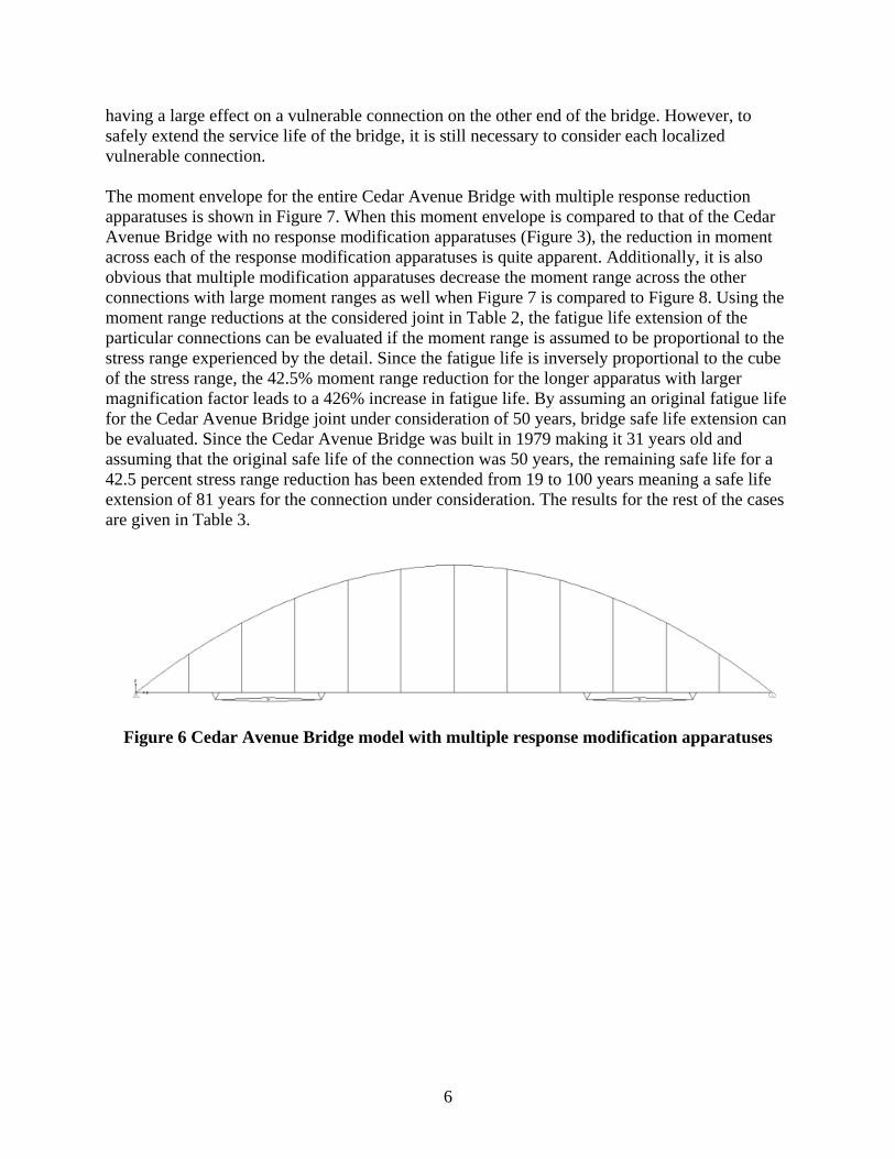
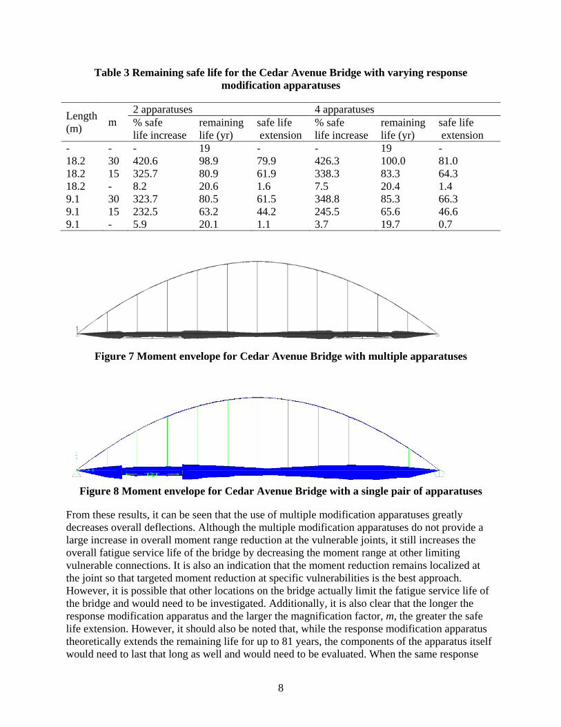
having a large effect on a vulnerable connection on the other end of the bridge. However, to safely extend the service life of the bridge, it is still necessary to consider each localized vulnerable connection. The moment envelope for the entire Cedar Avenue Bridge with multiple response reduction apparatuses is shown in Figure 7. When this moment envelope is compared to that of the Cedar Avenue Bridge with no response modification apparatuses (Figure 3), the reduction in moment across each of the response modification apparatuses is quite apparent. Additionally, it is also obvious that multiple modification apparatuses decrease the moment range across the other connections with large moment ranges as well when Figure 7 is compared to Figure 8. Using the moment range reductions at the considered joint in Table 2, the fatigue life extension of the particular connections can be evaluated if the moment range is assumed to be proportional to the stress range experienced by the detail. Since the fatigue life is inversely proportional to the cube of the stress range, the 42.5% moment range reduction for the longer apparatus with larger magnification factor leads to a 426% increase in fatigue life. By assuming an original fatigue life for the Cedar Avenue Bridge joint under consideration of 50 years, bridge safe life extension can be evaluated. Since the Cedar Avenue Bridge was built in 1979 making it 31 years old and assuming that the original safe life of the connection was 50 years, the remaining safe life for a 42.5 percent stress range reduction has been extended from 19 to 100 years meaning a safe life extension of 81 years for the connection under consideration. The results for the rest of the cases are given in Table 3.
Figure 6 Cedar Avenue Bridge model with multiple response modification apparatuses

7
Table 1 Deflection ranges for the Cedar Avenue Bridge model not including the bridge deck with 2 apparatuses
Length (m) m
Deflection (mm) 2 apparatuses 4 apparatuses
maximum minimum range % reduction maximum minimum range % reduction
- - 8.5 -13.8 22.3 - 7.3 -13.8 21.1 - 18.2 30 7.1 -10.5 17.6 21.1 5.6 -9.6 15.2 28.2 18.2 15 7.2 -10.8 18.0 19.2 5.8 -10.0 15.8 25.3 18.2 - 8.4 -13.7 22.1 0.7 7.2 -13.7 20.9 1.2 9.1 30 8.1 -12.0 20.0 10.2 6.7 -11.5 18.2 13.8 9.1 15 7.8 -12.2 20.1 9.9 6.7 -11.9 18.6 11.9 9.1 - 8.5 -13.8 22.2 0.2 7.2 -13.8 20.9 0.9
Table 2 Moment ranges for the Cedar Avenue Bridge model
Length (m) m
Moment (kN*m) 2 apparatuses 4 apparatuses
maximum minimum range % reduction maximum minimum range %
reduction - - 1615.6 -1050.3 2665.9 - 1598.7 -960.2 2558.9 - 18.2 30 943.6 -595.6 1539.2 42.3 907.9 -563.2 1471.1 42.5 18.2 15 1008.7 -635.8 1644.5 38.3 970.3 -593.4 1563.6 38.9 18.2 - 1593.0 -1003.7 2596.7 2.6 1570.4 -927.4 2497.9 2.4 9.1 30 985.7 -660.9 1646.7 38.2 966.8 -584.6 1551.3 39.4 9.1 15 1077.0 -709.8 1786.9 33.0 1058.8 -633.8 1692.7 33.9 9.1 - 1597.5 -1018.2 2615.7 1.9 1594.1 -933.7 2527.8 1.2
8
Table 3 Remaining safe life for the Cedar Avenue Bridge with varying response modification apparatuses
Length (m) m
2 apparatuses 4 apparatuses % safe life increase
remaining life (yr)
safe life extension
% safe life increase
remaining life (yr)
safe life extension
- - - 19 - - 19 - 18.2 30 420.6 98.9 79.9 426.3 100.0 81.0 18.2 15 325.7 80.9 61.9 338.3 83.3 64.3 18.2 - 8.2 20.6 1.6 7.5 20.4 1.4 9.1 30 323.7 80.5 61.5 348.8 85.3 66.3 9.1 15 232.5 63.2 44.2 245.5 65.6 46.6 9.1 - 5.9 20.1 1.1 3.7 19.7 0.7
Figure 7 Moment envelope for Cedar Avenue Bridge with multiple apparatuses
Figure 8 Moment envelope for Cedar Avenue Bridge with a single pair of apparatuses
From these results, it can be seen that the use of multiple modification apparatuses greatly decreases overall deflections. Although the multiple modification apparatuses do not provide a large increase in overall moment range reduction at the vulnerable joints, it still increases the overall fatigue service life of the bridge by decreasing the moment range at other limiting vulnerable connections. It is also an indication that the moment reduction remains localized at the joint so that targeted moment reduction at specific vulnerabilities is the best approach. However, it is possible that other locations on the bridge actually limit the fatigue service life of the bridge and would need to be investigated. Additionally, it is also clear that the longer the response modification apparatus and the larger the magnification factor, m, the greater the safe life extension. However, it should also be noted that, while the response modification apparatus theoretically extends the remaining life for up to 81 years, the components of the apparatus itself would need to last that long as well and would need to be evaluated. When the same response

9
modification device used in the response modification apparatus is used in the apparatus similar to that described by Patten et al. [6] without the mechanical amplifier, the safe life extension is barely increased. The response modification apparatuses without amplification would need a much larger response modification device with larger stiffness, to increase the safe life extension to the number of years calculated for the response modification apparatus with amplification. In the end, judicious use of multiple response apparatuses at targeted vulnerabilities achieves the best results for safe bridge life extension.

10

11
Chapter 3. Optimization of the Properties the Response Modification Apparatuses
While the use of multiple modification apparatuses has been shown to increase the efficacy of the approach, this section will investigate the optimization of properties, including spring stiffness, damper constant, member stiffness, and scissor jack geometry to maximize the reduction in stresses encountered by the potential vulnerabilities while minimizing the impact on the aesthetics of the bridge. In addition to looking at the effects of these properties, damping was also added to the structure to assure the robustness of the results. Damping was added to the superstructure model in the form of Rayleigh damping where the damping matrix is: C=μM+λK where μ and λ are determined using ξ = 0.5(μ/ω+ λ ω) using the natural frequencies of first two vertical modes of the unmodified bridge with a damping ratio, ξ, of two percent. The coefficients and natural frequencies were calculated from the numerical model in SAP2000 and are tabulated in Table 4.
Table 4 Cedar Avenue Bridge damping criteria
Period (s) Frequency (rad/s) Damping Stiffness Coefficient λ
Mass Coefficient μ
Mode 1 0.6086 10.32 2% 0.00163 0.2392 Mode 2 0.4422 14.21 2% To optimize the apparatus geometry, three different scissor jack sizes were chosen each with the same magnification value of 30 (see Gastineau et al. [1] for a description of magnification value). These sizes are given in Table 5 with the lengths and stiffness of the members within the apparatus that will be in axial tension and compression shown. Analyses were carried out for models using the three different geometries with and without damping as well as using various cross sectional areas for the axial members. The analyses by Gastineau et al. [1], [2] assumed rigid members being placed in the scissor jack for simplicity, and it is interesting to note that the most significant factor determining the performance of the apparatus is the cross section of the members. Results are given in Tables 6-11 for the three different apparatus configurations, with and without damping. It is clear that the larger the modification apparatus, meaning the attachment points are further apart, the better the performance. Additionally, the rigid apparatuses performed the best followed by the apparatuses with the largest cross sectional area. Although the smaller sized apparatuses have larger member stiffnesses due to their shorter member lengths, the larger apparatuses still performed better due to the larger differences in rotation at the attachment points. It should also be noted that for the majority of cases, damping in the superstructure had little effect on performance of the apparatuses. Table 12 shows the effect of different properties, stiffness and damping, of the modification device. It can be seen that changing one or the other by a factor of 100 has a slight effect on the overall performance and increasing both by a factor of 100 has about the same effect as just one. This confirms the previous assertion that the stiffness of the members (mainly the area) and the size of the

12
apparatus (the distance between attachment points) has the largest effect on the performance of the modification apparatus. To fully optimize these response modification apparatuses, the cost of the materials needs to be taken into account and the members with increased area have increased cost for the steel. Table 13 shows one possible way to compare the costs of the different modification apparatuses. It can be seen that the weight of steel divided by the amount of moment reduction is the lowest for the short apparatus using the W4x13 section and therefore most cost effective for a percent reduction. However, depending on the specific nature of the bridge vulnerability in detail, it may be necessary to use a configuration with higher cost to provide more moment reduction such as the short apparatus using the W14x145 sections.
Table 5 Apparatus member sizes, lengths, and stiffnesses
Apparatus Size Long Medium Short Leg Length (in) 358.70 179.35 89.55 Jack Length (in) 717 358.5 179 Leg Stiffness/Area (k/in3 80.85 ) 161.7 323.8
Table 6 Moment ranges at L3 connection for long apparatuses without damping
Apparatus Members None Rigid W4x13 W8x35 W8x67 W12x120 W14x145 Area (in2 ) 3.83 10.3 19.7 35.3 42.7 Leg Stiffness (k/in) - Inf 309.6 832.7 1592.7 2853.9 3452.19 Range (k-in) 22766 13500 22271 21477 21079 19555 19169 Maximum (k-in) 14220 8281 13990 13540 13160 12330 12120 Minimum (k-in) -8546 -5219 -8281 -7937 -7919 -7225 -7049 % reduction - 40.7 2.17 5.66 7.41 14.1 15.8
Table 7 Moment ranges at L3 connection for long apparatuses with damping
Apparatus Members None Rigid W4x13 W8x35 W8x67 W12x120 W14x145 Area (in2 ) 3.83 10.3 19.7 35.3 42.7 Leg Stiffness (k/in) - Inf 309.6 832.7 1592.7 2853.9 3452.19 Range (k-in) 21608 12301 21137 20434 19584 18492 18068 Maximum (k-in) 13800 7837 13510 13070 12540 11850 11580 Minimum (k-in) -7808 -4464 -7627 -7364 -7044 -6642 -6488 % reduction - 43.1 2.18 5.43 9.37 14.4 16.4
Table 8 Moment ranges at L3 connection for medium apparatuses without damping
Apparatus Members None Rigid W4x13 W8x35 W8x67 W12x120 W14x145 Area (in2 ) 3.83 10.3 19.7 35.3 42.7 Leg Stiffness (k/in) - Inf 619.3 1665.5 3185.4 5707.8 6904.4 Range (k-in) 22766 13707 22354 21798 21079 20187 19821 Maximum (k-in) 14220 8627 13960 13620 13160 12600 12370 Minimum (k-in) -8546 -5080 -8394 -8178 -7919 -7587 -7451 % reduction - 39.8 1.81 4.25 7.41 11.3 12.9

13
Table 9 Moment ranges at L3 connection for medium apparatuses with damping
Apparatus Members None Rigid W4x13 W8x35 W8x67 W12x120 W14x145 Area (in2 ) 3.83 10.3 19.7 35.3 42.7 Leg Stiffness (k/in) - Inf. 619.3 1665.5 3185.4 5707.8 6904.4 Range (k-in) 21608 13240 21266 20737 20076 19204 18866 Maximum (k-in) 13800 8392 13570 13230 12800 12230 12010 Minimum (k-in) -7808 -4848 -7696 -7507 -7276 -6974 -6856 % reduction 38.7 1.58 4.03 7.09 11.1 12.7
Table 10 Moment ranges at L3 connection for short apparatuses without damping
Apparatus Members None Rigid W4x13 W8x35 W8x67 W12x120 W14x145 Area (in2 ) 3.83 10.3 19.7 35.3 42.7 Leg Stiffness (k/in) - Inf 1240.3 3335.6 6379.7 11431.6 13828.0 Range (k-in) 22766 15388 22446 22100 21613 20945 20660 Maximum (k-in) 14220 9562 14000 13760 13450 13000 12830 Minimum (k-in) -8546 -5826 -8446 -8340 -8163 -7945 -7830 % reduction 32.4 1.40 2.93 5.06 8.00 9.25
Table 11 Moment ranges at L3 connection for short apparatuses with damping
Apparatus Members None Rigid W4x13 W8x35 W8x67 W12x120 W14x145 Area (in2 ) 3.83 10.3 19.7 35.3 42.7 Leg Stiffness (k/in) - Inf 1240.3 3335.6 6379.7 11431.6 13828.0 Range (k-in) 21608 14941 21379 21021 20569 19942 19679 Maximum (k-in) 13800 9383 13640 13400 13100 12680 12500 Minimum (k-in) -7808 -5558 -7739 -7621 -7469 -7262 -7179 % reduction 30.9 1.06 2.72 4.81 7.71 8.93
Table 12 Moment ranges at L3 connection for various device parameters
Apparatus Members None Rigid W14x145 W14x145 W14x145 W14x145 Area (in2 ) 42.7 42.7 42.7 42.7 Device Stiffness (k/in) - 11000 11000 110 110 Device Damping (k*s/in) - 300 3 3 300 Range (k-in) 22766 15388 20602 20602 20660 20608 Maximum (k-in) 14220 9562 12790 12790 12830 12800 Minimum (k-in) -8546 -5826 -7812 -7812 -7830 -7808 % reduction - 32.4 9.51 9.51 9.25 9.48
Table 13 Comparison of cost per percent reduction for different apparatus characteristics
Apparatus Size Member Size W4x13 W8x35 W8x67 W12x120 W14x145 Long Lbs /
% Reduction
766.4 827.9 919.2 1069.4 1137.4 Medium 564.5 596.8 649.5 741.3 785.3 Short 475.9 499.8 540.6 603.8 630.1

14
From the analyses performed in this section, it is clear that the most important factor in the apparatus is the member cross sectional area and the overall length between the attachment points of the modification apparatus. Additionally, the smallest sized apparatuses seem to be the most cost effective but would need to be analyzed to make sure they provide adequate lifetime extension. Now that optimization parameters have been addressed, the use of a semi-active control device will be discussed in the next section.

15
Chapter 4. Extension of the Modification Framework to Include Semi-Active Devices
While passive modification devices can often be selected to provide adequate response reduction if the loading is known, the ability of the modification device to adapt to various loading scenarios is very attractive. This section will investigate extending the modification framework to include semi-active damping devices whose properties can be modified to manipulate structural response. These properties can theoretically be governed by a control algorithm which incorporates real-time data of loadings subjected on the bridge potentially measured using WIM (weigh-in-motion) technologies as well as other bridge health monitoring equipment. Before looking at the complicated structure of the Cedar Avenue Bridge, a simple beam example will demonstrate the utility of a semi-active system.
4.1 Frequency Response Analysis of a Simple Beam
Due to the dynamic nature of bridge loadings, varying levels of dynamic amplification will occur at different loading frequencies. At certain resonant frequencies, large amplifications may occur that will completely negate the advantages of the response modification apparatus for the bridge structure. If a particular loading is detected at a problematic frequency, these resonant frequencies can be manipulated by varying the parameters of the response modification device so that large amplifications will not occur. To show these effects, the simple beam model described by Gastineau et al. [1] was utilized to perform a frequency domain analysis of the system due to a periodic load applied at midspan and a description of this model is included for completeness. A finite element numerical model of a beam with a response modification apparatus was developed in SAP2000 using frame elements which used a 10 element W40x324 beam (I=25,600 in4, E=29,000 ksi) to span a length of 50 feet between simple supports and rigid elements (E=1x10¹⁰ksi) for all members of the response modification apparatus. The apparatus spanned the entire length of the beam and had a magnification factor of 12.5 and the response modification device had a stiffness of k =120 kip-ft. All connections within the apparatus were pin connections except for when the connection to the wide flange section was a rigid moment connection. Using this finite element model defined in SAP2000, mass and stiffness matrices were exported and used to obtain the state space representation in MATLAB. Using MATLAB, frequency response analyses for a load and the displacement at midspan were carried out for the beam without the response modification apparatus, as well as with the response modification apparatus consisting of an response modification device with fixed damping and stiffness. The magnitude of the transfer function, a mathematical relationship between an input that can vary with frequency and an output, between load and displacement is plotted on a log-log scale in Figure 9, and it is clear that when the apparatus is present significant reductions (60 percent) occur at smaller frequencies but amplification at higher frequencies can occur. In addition, at certain higher frequencies, deflections of the beam with the response modification apparatus can exceed the deflections of the beam without the response modification apparatus. Therefore, to further ensure response reduction over a larger range of loading frequencies and that stress ranges are kept at a safe level, a semi-active response modification device with properties that can be manipulated depending on loading conditions might prove to be advantageous.
16
4.2 Frequency Response Analysis of a Cedar Avenue Bridge
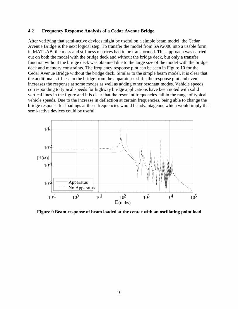
After verifying that semi-active devices might be useful on a simple beam model, the Cedar Avenue Bridge is the next logical step. To transfer the model from SAP2000 into a usable form in MATLAB, the mass and stiffness matrices had to be transformed. This approach was carried out on both the model with the bridge deck and without the bridge deck, but only a transfer function without the bridge deck was obtained due to the large size of the model with the bridge deck and memory constraints. The frequency response plot can be seen in Figure 10 for the Cedar Avenue Bridge without the bridge deck. Similar to the simple beam model, it is clear that the additional stiffness in the bridge from the apparatuses shifts the response plot and even increases the response at some modes as well as adding other resonant modes. Vehicle speeds corresponding to typical speeds for highway bridge applications have been noted with solid vertical lines in the figure and it is clear that the resonant frequencies fall in the range of typical vehicle speeds. Due to the increase in deflection at certain frequencies, being able to change the bridge response for loadings at these frequencies would be advantageous which would imply that semi-active devices could be useful.
Figure 9 Beam response of beam loaded at the center with an oscillating point load
10 -1 10 0 10 1 10 2 10 3 10 4 10 5
10 -6
10 -4
10 -2
10 0
(rad/s)
|H(ω)|
Apparatus No Apparatus

17
Figure 10 Bridge frequency response for deflection at the L3 joint and 72 kip load at
midspan for the Cedar Avenue Bridge numerical model without the deck
10 1 10 2 10 -4
10 -3
10 -2
10 -1
10 0
10 1
10 2
(rad/s)
no Apparatuses with Apparatuses
30 mph 80 mph
ω)|
Table 14 shows equivalent frequencies for varying truck speeds where L (ft) is the assumed distance between point loads, which is calculated based on four possible assumptions: (1) L=358.5 which is the whole length of the bridge so one truck on the bridge at a time repeating; (2) L=30 feet which is the distance between the two heavy axles for the case of a fatigue load truck (see [1] for loading conditions); (3) L=44 feet which is the distance between the front axle and the rear axle; and (4) L=14 feet which is the distance between the front axle and the first heavy axle. Case two is the most severe case due to the heaviest loads and has frequencies that lie within the largest amplifications in the frequency response plot. Table 15 shows the reductions and amplifications that can be caused by the passive response modification apparatus for vehicles traveling at varying speeds. It is shown that for certain loading frequencies the response is decreased up to 100% using the response modification apparatuses but for other loading frequencies that the response can be increased by 8700% over the original bridge structure. Therefore, being able to change the properties of the device to shift the frequency response plot is essential.
Table 14 Fatigue truck loading frequencies
L (ft) Frequency (rad/s) 55 mph 60 mph 80 mph
358.5 1.41 1.54 2.06 30 16.89 18.43 24.57 44 11.52 12.57 16.76 14 36.20 39.49 52.66
|H(

18
Table 15 Fatigue truck loading speeds with increased deflections
mph L (ft) Frequency (rad/s) Modified Displacement Magnitude (in)
Unmodified Displacement Magnitude (in)
% Decrease
32.4
30
9.95 0.08209 0.634 87 39.3 12.08 4.95 0.0563 -8629 51.8 15.92 0.635 0.154 -312 60.7 18.66 1.05 22.6 95 62.5 19.19 46.19 0.927 -4877 69.3 21.28 0.186 59.1 100 70.7 21.73 8.89 0.101 -8757

19
Chapter 5. Conclusions
In this report, it is clear that the response modification approach initially outlined by Gastineau et al. [1] has been further investigated and refined and can safely extend the fatigue service life of vulnerable connections on steel bridges. The use of multiple response modification apparatuses was investigated using time domain dynamic numerical analyses and was shown to outperform the use of apparatuses in only one location. Optimization of the apparatus size, member properties, and device properties was carried out through numerical analyses but would ultimately need to be analyzed on a case-by-case basis depending on the amount of life extension necessary for a specific case. In the frequency domain, the implementation of a semi-active modification device was shown to be both advantageous and necessary using both a simple beam model and a simple model of the Cedar Avenue Bridge. From the frequency response plots, it is clear that, even with the modification apparatus, some loading frequencies may increase response so that a semi-active device is necessary. Further work to extend the approach to other vulnerable bridge situations and the development of a semi-active control strategy should be carried out in the future in both the frequency and time domain. Additionally, one needs to be certain that the new connections from the apparatus to the structure do not create additional fatigue vulnerabilities, and the connection details should be further investigated as well.

20

21
References
1. A.J. Gastineau, S.F. Wojtkiewicz, A.E. Schultz. Response Modification for Enhanced Operation and Safety of Bridges. Final Report, Center for Transportation Studies, University of Minnesota, Minneapolis, MN, Dec. 2010.
2. A.J. Gastineau, S.F. Wojtkiewicz, A.E. Schultz. “Safe Life Extension of Bridges using
Structural Response Modification Techniques.” EURODYN: Proceedings of the 10th International Conference on Structural Dynamics, Leuven, Belgium, July 4-6, 2011.
3. A.J. Gastineau, S.F. Wojtkiewicz, A.E. Schultz. “Response Modification Approach for
Safe Extension of Bridge Life.” (in press) ASCE Journal of Bridge Engineering.
4. American Association of State Highway and Transportation Officials (AASHTO). Manual for Bridge Evaluation, 1st Ed., AASHTO, Washington, D.C. 2008.
5. D.J. Thompson, A.E. Schultz. Development of an advanced structural monitoring
system. Final Report, Center for Transportation Studies, University of Minnesota, Minneapolis, MN, Nov. 2010.
6. W.N. Patten, J. Sun, G. Li, J. Kuehn, G. Song. “Field Test of an Intelligent Stiffener for
Bridges at the I-35 Walnut Creek Bridge.” Earthquake Engineering Structural Dynamics, 28 (2), 1999, pp. 109-126.