Embed Size (px)
Citation preview

Eur. Phys. J. Special Topics 224, 3361–3377 (2015)c⃝ EDP Sciences, Springer-Verlag 2015DOI: 10.1140/epjst/e2015-50094-x
THE EUROPEANPHYSICAL JOURNALSPECIAL TOPICS
Regular Article
Insects have hairy eyes that reduce particledeposition
G.J. Amador1, F. Durand1, W. Mao1, S. Pusulri2, H. Takahashi4, V.-T. Nguyen4,I. Shimoyama4, A. Alexeev1, and D.L. Hu1,3,a
1 Schools of Mechanical Engineering, Georgia Institute of Technology, Atlanta, USA2 Biomedical Engineering, Georgia Institute of Technology, Atlanta, USA3 Biol. Georgia Institute of Technology, Atlanta, USA4 Department of Mechano-Informatics, The University of Tokyo, Tokyo, Japan
Received 29 April 2015 / Received in final form 2 November 2015Published online 15 December 2015
Abstract. An insect’s eyes may make up to 40% of its body’s sur-face, and are in danger of being coated by foreign particles such asdust and pollen. To protect them, several insect species possess anarray of ocular hairs evenly spaced between each photoreceptor unit.Although these hairs have been observed for over 50 years, their pur-pose remains a mystery. In this study, we elucidate the function ofocular hairs using a combination of experiments, numerical simulationand micro-fabrication. We measure the eyes of 18 species of insects andfind that the length of their ocular hairs is equal to their spacing. Weconduct wind tunnel experiments using both an insect eye mimic andan at-scale fabricated micro-pillar array of the same dimensions as theinsect eye. Our experiments and simulations show that ocularhairs reduce airflow at the eye surface by up to 90%. We concludethat ocular hairs act similarly to mammalian eyelashes: as insects fly,ocular hairs deflect incoming air and create a zone of stagnant air.Airflow and particle deposition are reduced dramatically, while lightis only minimally occluded. Micro-scale ocular hairs may find applica-tion in the deployment of sensors outdoors, for which accumulation ofairborne dust and pollen has no current solution.
1 Introduction
Flying insects experience the world at high speed, relying on vision to make split-second decisions about predator or obstacle avoidance [1]. The visual response to afruit fly encountering an obstacle is 50ms [2], while the visual startle response ofa long-legged fly is less than 5ms [3]. Vision is so important to these insects, thatmany have compound eyes composed of hundreds to thousands of lenses and nearly360-degree fields of view. Several insect species have arrays of hairs on their eyes.The fact that they are there is familiar [4], but their function is not well understood.
a e-mail: [email protected]
3362 The European Physical Journal Special Topics
100
101
102
10310
0
101
102
103
Hover flyFruit flyEocene flyMosquitoMidgeHouse flyGreen bottle flyMarch flyFungus gnatTsetse fly
Diptera
Parasitoid waspHoney beeCarpenter antFire ant
Hymenoptera
NymphalidaeForage looper moth
Lepidoptera
Flour beetle
Coleoptera
Bark lice
Psocoptera
(µm)
L (µ
m)
(d)
(b) (a)
L
S
(c)
Fig. 1. Insect ocular hairs. (a–b) The eye of a fruit fly, Drosophila melanogaster. Scalebars represent: (a) 250 µm and (b) 20 µm. (c) Schematic showing geometrical parametersmeasured. (d) Relationship between hair length L and spacing S for 18 species of insectsspanning 5 orders. Dashed line indicates L = S. The results are outlined in Table 1.
In this study, we use a combination of experiments, simulation, and micro-fabricationto elucidate a function of the insect ocular hairs.Most arthropods, like the fruit fly in Fig. 1a, possess compound eyes. Unlike
the simple eyes found in vertebrates [5], these are composed of an array of hexag-onal photoreceptor units, called ommatidia, and typically look like Fig. 1b. Eachommatidium consists of an individual lens that captures incoming light and trans-fers the signal to the brain through nerves [6]. In certain insects, like fruit flies andhoney bees, hairs have been observed to be present between ommatidia, as shown inFig. 1b. Although the purpose of these hairs is unknown, previous work has shownthat they may play a role in sensing air currents [7,8]. A previous study found thathoney bees fly 11% slower when their ocular hairs are shaved, suggesting theirpotential role in sensing air flow during flight [7,8]. In crickets, these hairs serve asmechanosensors that detect particle accumulation on the eye and trigger head
Dynamics of Animal Systems 3363
Table 1. Tabulated hair data for insects and other arthropods, including ocular hair center-to-center spacing S, length L, and thickness h. * Indicates the 6 species of arthropods thatare not part of the class Insecta. N/A indicates samples where the species name and/orfamily name were not provided by the source.
Order Family Species Common Name Hairs present? S (µm) L (µm) h (µm) SourceSiphonaptera N/A N/A Flea No 28Mecoptera Boreidae Caurinus tlagu Snow scorpion fly No 28Mecoptera N/A N/A Scorpion fly No 28Mecoptera N/A N/A Scorpion fly No 28Diptera Syrphidae Chrysotoxum intermedium Hoverfly Yes 20.0 12.5 1.3 29Diptera Drosophilidae Drosophila melanogaster Fruit fly Yes 17.5 17.5 1.5 HereDiptera Dolichopodidae Neurotexia Primula Eocene fly Yes 15.0 20.0 1.6 30Diptera Muscidae Musca domestica House fly Yes 30.0 20.0 1.0 31Diptera Drosophilidae Drosophila virilis Fruit fly Yes 18.0 18.0 1.2 HereDiptera Calliphoridae Lucilia sericata Green bottle fly Yes 17.0 16.0 1.0 HereDiptera Bibionidae Bibio johannis March fly Yes 60.0 165.0 2.7 32Diptera Glossinidae Glossina palpalis Tsetse fly Yes 90.5 10.5 1.8 33Diptera Mycetophilidae Novakia Miloi Fungus gnat Yes 6.5 6.2 1.4 34Diptera Hippoboscidae N/A Louse fly No 28Diptera Culicidae N/A Mosquito Yes 20.0 30.0 1.1 35Diptera Nematocera N/A Midge Yes 10.0 11.0 1.3 36Lepidoptera Nymphalidae Aglais io Nymphalidae Yes 22.5 500.0 3.8 37Lepidoptera Erebidae Caenurgina erechtea Forage looper moth Yes 130.0 13.0 1.0 HereColeoptera Silphidae Oxelytrum gistel No 38Coleoptera Curculionidae Sitophilus zeamais Maize weevil No 28Coleoptera Scarabaeidae Cotinis mutabilis Figeater beetle No 28Coleoptera Tenebrionidae Tribolium Flour beetle Yes 14.2 19.8 2.4 33Coleoptera Histeridae N/A Clown beetle No 28Coleoptera Carabidae N/A Bombardier beetle No 28Coleoptera Scarabaeidae N/A Scarab beetle No 28Coleoptera Coccinellidae N/A Lady bug No 28Raphidioptera N/A N/A Snakeflies No 28Hymenoptera Trichogrammatidae Trichogramma evanescens Parasitoid wasp Yes 12.5 5.0 39Hymenoptera Apidae Apis melifera Honey bee Yes 75.0 257.0 7.0 HereHymenoptera Formicidae Solenopsis invicta Fire ant Yes 189.8 58.9 10.1 40Phthiraptera Pediculidae Pediculus humanus capitis Head louse No 33Psocoptera N/A N/A Bark lice Yes 11.7 41.5 1.4 28Hemiptera Cimicidae Cimex lectularius Bed bug No 42Hemiptera Gerridae N/A Water strider No 43Hemiptera Coreidae N/A Leaf-footed bug No 44Hemiptera Miridae N/A Leaf bug No 45Thysanoptera N/A N/A Thrip No 28Blattodea Rhinotermitidae Coptotermes elisae Termite No 46Blattodea N/A N/A Cockroach No 28Zoraptera Zorotypidae N/A Angel insect No 28Plecoptera Nemouridae N/A Stonefly No 28Plecoptera Peltoperlidae N/A Roach like stonefly No 28Orthoptera Rhaphidophoridae N/A Camel cricket No 28Orthoptera Gryllidae Acheta domesticus House cricket No 28Phasmatodea N/A N/A Walking stick No 28Odanta Coenagrionidae N/A Damslefly No 28Odonata Gomphidae N/A Clubtail dragonfly No 28Collemobola* N/A N/A Spring tail No 28Protura* N/A N/A Proturans No 28Diplura* N/A N/A N/A No 28Isopoda* Armadillidiidae N/A Pill bug No 47Araneae* Palpimanidae Levymanus gershomi Spider No 48Araneae* Salticidae N/A Jumping spider No 47
cleaning motions [9]. The short ocular hairs on the eyes of fruit flies develop similarlyto sensory hairs, or cilia, and so possess sensory neurons with a branched extensionof a nerve cell [10]. In the current study, we focus not on the the ocular hair’s sensingability, but on the effect they have on the incoming flow.Hair is the ultimate multifunctional structure in both invertebrates and verte-
brates, serving a number of important roles in sensing [11–13], insulation [14], protec-tion [15,16], and filtration [17,18]. The hairs on the antennae of moths divert incoming
3364 The European Physical Journal Special Topics
airflow and stretch its streamlines. By stretching the flow profile, these hairs improvethe spatial resolution of the antennae’s chemoreception [19,20]. In a previous study,researchers discovered that the bristled wings of thrips also resist airflow and gener-ate sufficient drag-based lift for successful flapping flight [21]. We previously showedthat mammalian eyelashes reduce evaporation and accumulation of airborne partic-ulates [22]. In this study, we hypothesize insect ocular hairs serve a similar purposeto mammalian eyelashes by preventing airborne particle accumulation and possiblywater loss.Water management in arthropods is critical for homeostasis, especially because of
their large surface area to volume ratios. Greater surface area means the animal ismore exposed to the environment and experiences higher rates of exchange, e.g., waterloss in dry conditions and moisture absorption in wet conditions. Previous workershave found that, for insects, most of their water is lost through the cuticle [23].Respiration also accounts for some water loss, but only 5–20% [23]. Since compoundeyes contribute a substantial amount to the overall surface area of arthropods, waterloss through them may be non-trivial.In this study, we investigate the function of the ocular hairs of insects. We use
experiments and numerical simulations to shed light on the aerodynamics of flowaround arrays of hairs similar to those on insects. In Sect. 2, we present our method-ology. In Sect. 3.1, we present our measurements of insect ocular hairs. In Sect. 3.2,we present the results of our wind tunnel tests measuring evaporation of insect eyemimics. In Sect. 3.3, we present results of our numerical simulations. In Sect. 3.4, wepresent our micro-fabrication of ocular hairs of the insect, which we test using windtunnel experiments. In Sect. 4, we present a discussion of our results and avenues forfuture work, and provide concluding remarks in Sect. 5.
2 Materials and methods
2.1 Anatomical measurements
We approximate the percentage of surface area taken up by the compound eyes ofinsects. We use values published in the literature [24,25], as well as unpublishedpictures found online showing dorsal views [26–30]. From the pictures, we measure thelength and width of the body and the radius of the eyes. Using these measurements, weapproximate the body as cylindrical and compound eyes as hemispherical to calculatesurface area. When insects fly, they do so headfirst, and so may expose their eyes togreat amounts of airflow. To determine the amount of frontal area taken up by thecompound eyes, we use unpublished pictures of frontal views [31–35].Using digital scanning electron microscope (SEM) images from our lab, literature
[4,36–43], and unpublished images from the internet [44–55], we observe the eyes of48 species of insects and 6 species of arthropods that are not part of the class Insecta.For the species observed to possess ocular hairs we use SEM images, like the oneshown in Fig. 1b, to measure the geometry of the hair arrays, including the hairlength L, thickness h, and center-to-center spacing S. The length L and spacing Sare shown schematically in Fig. 1c.
2.2 Hairy compound eye mimic
To understand how hairs affect the airflow to the eye of an insect, a replica isconstructed in order to perform controlled experiments. To simplify the geometry,the curvature of the eye is neglected and a flat eye surface is used for the mimic.
Dynamics of Animal Systems 3365
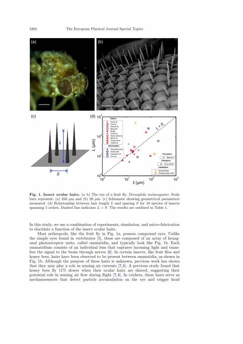
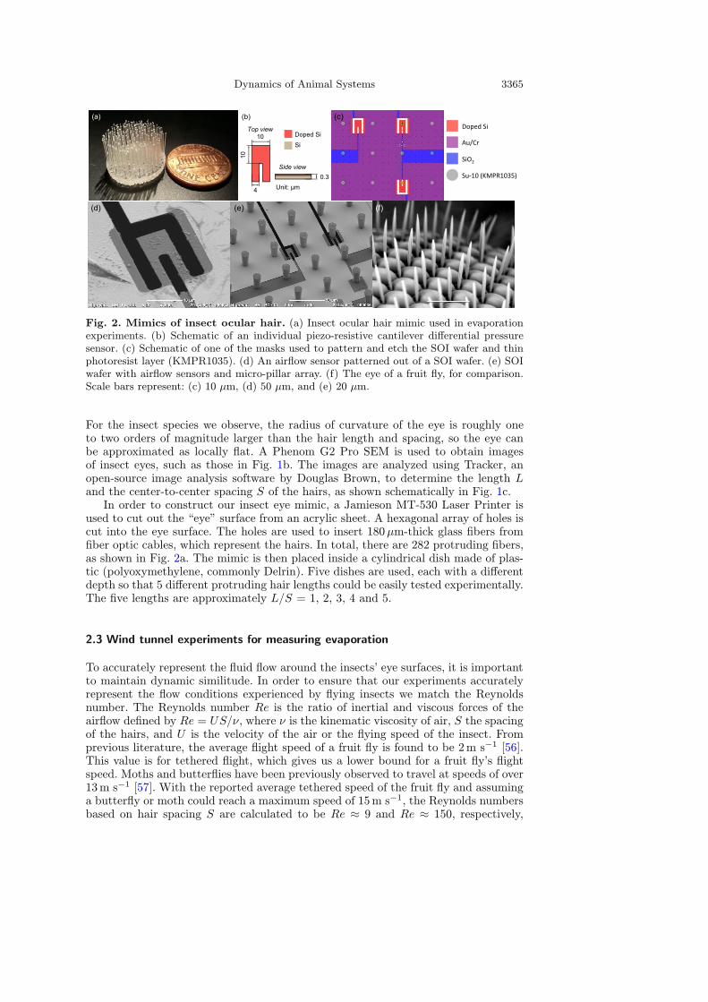
Fig. 2. Mimics of insect ocular hair. (a) Insect ocular hair mimic used in evaporationexperiments. (b) Schematic of an individual piezo-resistive cantilever differential pressuresensor. (c) Schematic of one of the masks used to pattern and etch the SOI wafer and thinphotoresist layer (KMPR1035). (d) An airflow sensor patterned out of a SOI wafer. (e) SOIwafer with airflow sensors and micro-pillar array. (f) The eye of a fruit fly, for comparison.Scale bars represent: (c) 10 µm, (d) 50 µm, and (e) 20 µm.
For the insect species we observe, the radius of curvature of the eye is roughly oneto two orders of magnitude larger than the hair length and spacing, so the eye canbe approximated as locally flat. A Phenom G2 Pro SEM is used to obtain imagesof insect eyes, such as those in Fig. 1b. The images are analyzed using Tracker, anopen-source image analysis software by Douglas Brown, to determine the length Land the center-to-center spacing S of the hairs, as shown schematically in Fig. 1c.In order to construct our insect eye mimic, a Jamieson MT-530 Laser Printer is
used to cut out the “eye” surface from an acrylic sheet. A hexagonal array of holes iscut into the eye surface. The holes are used to insert 180µm-thick glass fibers fromfiber optic cables, which represent the hairs. In total, there are 282 protruding fibers,as shown in Fig. 2a. The mimic is then placed inside a cylindrical dish made of plas-tic (polyoxymethylene, commonly Delrin). Five dishes are used, each with a differentdepth so that 5 different protruding hair lengths could be easily tested experimentally.The five lengths are approximately L/S = 1, 2, 3, 4 and 5.
2.3 Wind tunnel experiments for measuring evaporation
To accurately represent the fluid flow around the insects’ eye surfaces, it is importantto maintain dynamic similitude. In order to ensure that our experiments accuratelyrepresent the flow conditions experienced by flying insects we match the Reynoldsnumber. The Reynolds number Re is the ratio of inertial and viscous forces of theairflow defined by Re = US/ν, where ν is the kinematic viscosity of air, S the spacingof the hairs, and U is the velocity of the air or the flying speed of the insect. Fromprevious literature, the average flight speed of a fruit fly is found to be 2m s−1 [56].This value is for tethered flight, which gives us a lower bound for a fruit fly’s flightspeed. Moths and butterflies have been previously observed to travel at speeds of over13m s−1 [57]. With the reported average tethered speed of the fruit fly and assuminga butterfly or moth could reach a maximum speed of 15m s−1, the Reynolds numbersbased on hair spacing S are calculated to be Re ≈ 9 and Re ≈ 150, respectively,
3366 The European Physical Journal Special Topics
for air at ambient conditions. These Reynolds numbers dictate the minimum andmaximum airflow speeds for the experiments.The airflow to the eye is provided by a small wind tunnel, where parts include:
a DC-powered fan, diffuser, honeycombed laminarizer, settling chamber, nozzle, andair-guiding duct. The wind tunnel is the same as the one used in Amador et al. [22].The eye model is placed in the testing area atop a 10−5 g precision scale (MettlerToledo NewClassic MF, Model MS205DU), with the water-filled dish and protrudinghairs facing upwards toward the fan. The plastic dish with the insect ocular mimicis filled with water using a micropipette until the water surface reaches the rim.The water surface represents the eye surface. Each dish and mimic is filled withthe same volume of water for each trial. To minimize the water meniscus at eachprotruding fiber, the fibers were treated with a commercially available hydrophobicspray (Cytonix LLC, WX2100). An optical microscope (Olympus SZX16) was usedto verify the minimization of the meniscus.To simulate the airflow experienced by the fruit fly and moth during flight, the
wind speed U is set to 0.11m/s and 1.1m/s, respectively. The scale is connected toa computer and a mass reading is taken every 10 seconds for 10 minutes, resulting in60 total readings per trial. Three trials are conducted for each hair length, includingone without hair. The average evaporation rate is found using a least-squares linearregression. Trials are run without any airflow to find the control value for waterevaporation, 19.5 µg/s. This value is subtracted from our measured evaporation ratesto ensure the rates reported represent only evaporation from the perpendicularlyincident flow. The trials were run indoors over a series of weeks in the summer of 2013in a room of temperature T = 21.5± 0.5C and relative humidity at RH = 46± 2%.The small variance in temperature and humidity allowed for accurate measurementsof evaporation rate.
2.4 Numerical methods
We employ a lattice Boltzmann model (LBM) [58–61] to examine the interactions be-tween arrays of hair, the ocular surface, and a viscous flow. The LBM is a mesoscalecomputational model for simulating hydrodynamic flows governed by the Navier-Stokes equations. The method is based on the time integration of a discretizedBoltzmann equation fi(r+ ci∆t, t+∆t) = fi(r, t) +Ω[f(r, t)] for a particle’s distrib-ution function f . Here, ci is the fluid particle’s velocity in the direction i at a latticenode r at time t, ∆t is the time step, and Ω is the collision operator accounting for thechange in f due to instantaneous collisions at the lattice nodes. The moments of thedistribution function are used to calculate fluid density ρa =
∑i fi, the momentum
density j =∑i cifi, and the stresses Π =
∑i cicifi. We use a three-dimensional 19
velocity model (3D19Q) defined on a simple cubic lattice and a multiple-relaxation-time collision operator [60].The simulations are conducted in a rectangular computational box large enough
that its size does not affect the flow around the eye. The eye is modeled as a circularflat surface with the diameter 12S located at the center of a circular face with thediameter 24S. Each hair is modeled as a sequence of static beads that are uniformlydistributed along its length L. Here, we neglect the effect of hair flexibility on theemerging fluid flow.Frictional force in the form of the Stokes drag Ff = −ξuf is used to account the
effect of hair on the flowing air [62,63]. Here, uf is the fluid velocity and ξ = 6πµσ isthe drag coefficient with σ being the effective hydrodynamic radius of the seta and µthe dynamic viscosity of air. The force is distributed to LBM nodes surrounding theeyelash using a delta function [64]. Interpolated bounce-back rule is used to impose
Dynamics of Animal Systems 3367
the no-slip and no-penetration boundary conditions at the ocular surface [65]. Wehave previously extensively used LBM to study flows near solid surfaces covered withhair-like filaments [22,66–69].
2.5 Fabrication of airflow sensors within pillar arrays
In this section we present the fabrication techniques used to create micron-scaledpillar arrays with airflow sensors. The pillar arrays are fabricated on top of a SOI(silicon on insulator) wafer with piezo-resistive cantilevers that bend in response to thedynamic pressure of flowing air. A schematic of the cantilever is shown in Fig. 2b.The differential pressure sensors have been used previously by the authors to measurethe differential pressure generated by airflows [70,71] and drag generated by an arrayof bristles [21]. The cantilevers measure the pressure produced by air flowingin between the pillar arrays, so we may use them to measure flow penetration.Details on the fabrication techniques used are outlined in Gel & Shimoyama [72]and Thanh-Vinh et al. [73], but for completeness we will present a brief summary.The fabrication process begins with a SOI wafer consisting of three layers, a
0.3-µm thick silicon layer on top, then a 0.4-µm thick silicon dioxide layer below,and finally a 300-µm thick silicon layer at the bottom. The top silicon layer of theSOI wafer is doped to change its electrical properties using ion implantation with adose of 1015 cm−2 of arsenic at 10 keV for 585 seconds and 40 keV for 303 seconds.Thin layers of gold and chromium are deposited through evaporation in a vacuum,with thicknesses of 30 nm and 3 nm, respectively. First, the gold and chromium layersare patterned using photolithography and wet-etching. The top silicon layer is thenetched using Inductive Coupled Plasma-RIE (ICP-RIE) using gold and chromiumpatterns as masks. The etching process reveals the area where the microcantileverwill reside, following the mask schematic in Fig. 2c. After that, the piezoresistorsat the root of the cantilevers are revealed by patterning and etching the gold andchromium layers. The micropillar array is fabricated by spin coating and pattern-ing a KMPR1035 photoresist (MicroChem Corp, MA, USA) layer with a thickness of35 µm on top of the wafer. Finally, through holes underneath the cantilever are formedby etching the bottom silicon layer using ICP-RIE and then the silicon dioxide layerare etched by vapor hydrofluoric acid to release the cantilever as shown in Fig. 2b,c.The microcantilever is only made up of the thin layer of doped silicon with a thingap surrounding it to allow air to flow through and bend the cantilever. SEM imagesof the final product are shown in Fig. 2d,e. We use three sensors on each wafer, onebetween the pillars, the other underneath a pillar, and a third without the bottometched out to measure the change in electrical resistance of the wafer due to thechange in temperature.Qualitatively, the micropillar arrays closely resemble those found interspersed
throughout the eyes of flying insects, like the fruit fly shown in Fig. 2f. Thepillars are also within the range of geometries of insect ocular hairs. Their lengthL of 35 µm and thickness h of 5 µm are similar to those observed on insects.
2.6 Wind tunnel experiments with micropillars
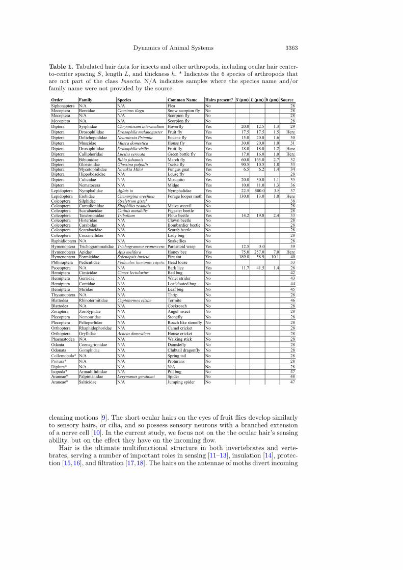
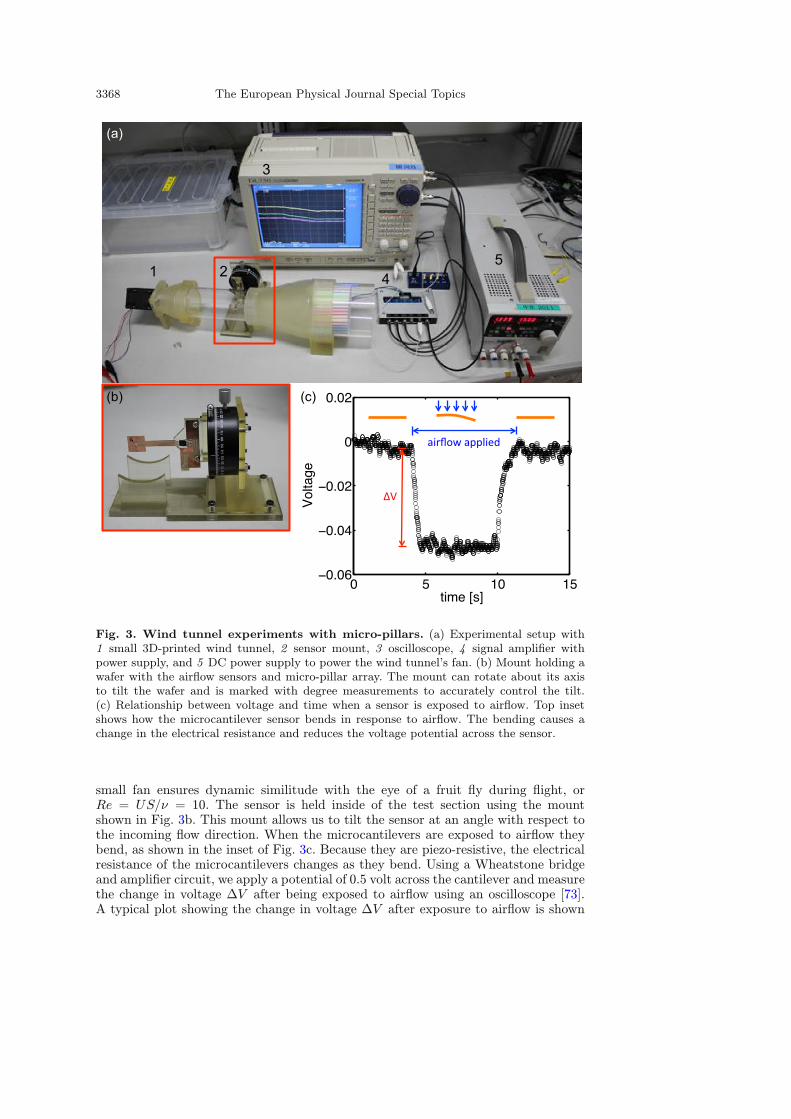
We use a small wind tunnel to expose our micro-pillar arrays to airflow. The windtunnel is fabricated using a 3D printer and is shown in Fig. 3a. The small fan on theleft is powered by a DC power supply and pulls air through the wind tunnel. An arrayof tightly packed straws at the inlet of the wind tunnel (on the right) laminarizes theflow and the nozzle makes it uniform. The velocity U of the flow supplied by the
3368 The European Physical Journal Special Topics
Fig. 3. Wind tunnel experiments with micro-pillars. (a) Experimental setup with1 small 3D-printed wind tunnel, 2 sensor mount, 3 oscilloscope, 4 signal amplifier withpower supply, and 5 DC power supply to power the wind tunnel’s fan. (b) Mount holding awafer with the airflow sensors and micro-pillar array. The mount can rotate about its axisto tilt the wafer and is marked with degree measurements to accurately control the tilt.(c) Relationship between voltage and time when a sensor is exposed to airflow. Top insetshows how the microcantilever sensor bends in response to airflow. The bending causes achange in the electrical resistance and reduces the voltage potential across the sensor.
small fan ensures dynamic similitude with the eye of a fruit fly during flight, orRe = US/ν = 10. The sensor is held inside of the test section using the mountshown in Fig. 3b. This mount allows us to tilt the sensor at an angle with respect tothe incoming flow direction. When the microcantilevers are exposed to airflow theybend, as shown in the inset of Fig. 3c. Because they are piezo-resistive, the electricalresistance of the microcantilevers changes as they bend. Using a Wheatstone bridgeand amplifier circuit, we apply a potential of 0.5 volt across the cantilever and measurethe change in voltage ∆V after being exposed to airflow using an oscilloscope [73].A typical plot showing the change in voltage ∆V after exposure to airflow is shown
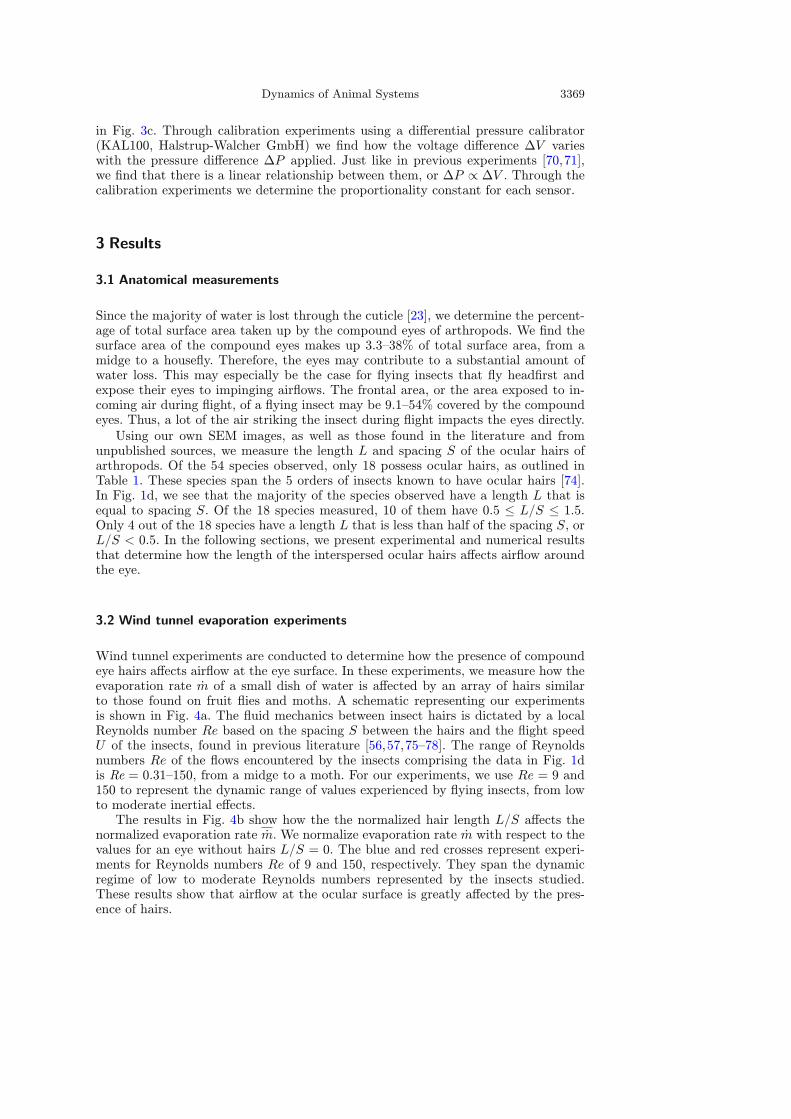
Dynamics of Animal Systems 3369
in Fig. 3c. Through calibration experiments using a differential pressure calibrator(KAL100, Halstrup-Walcher GmbH) we find how the voltage difference ∆V varieswith the pressure difference ∆P applied. Just like in previous experiments [70,71],we find that there is a linear relationship between them, or ∆P ∝ ∆V . Through thecalibration experiments we determine the proportionality constant for each sensor.
3 Results
3.1 Anatomical measurements
Since the majority of water is lost through the cuticle [23], we determine the percent-age of total surface area taken up by the compound eyes of arthropods. We find thesurface area of the compound eyes makes up 3.3–38% of total surface area, from amidge to a housefly. Therefore, the eyes may contribute to a substantial amount ofwater loss. This may especially be the case for flying insects that fly headfirst andexpose their eyes to impinging airflows. The frontal area, or the area exposed to in-coming air during flight, of a flying insect may be 9.1–54% covered by the compoundeyes. Thus, a lot of the air striking the insect during flight impacts the eyes directly.Using our own SEM images, as well as those found in the literature and from
unpublished sources, we measure the length L and spacing S of the ocular hairs ofarthropods. Of the 54 species observed, only 18 possess ocular hairs, as outlined inTable 1. These species span the 5 orders of insects known to have ocular hairs [74].In Fig. 1d, we see that the majority of the species observed have a length L that isequal to spacing S. Of the 18 species measured, 10 of them have 0.5 ≤ L/S ≤ 1.5.Only 4 out of the 18 species have a length L that is less than half of the spacing S, orL/S < 0.5. In the following sections, we present experimental and numerical resultsthat determine how the length of the interspersed ocular hairs affects airflow aroundthe eye.
3.2 Wind tunnel evaporation experiments
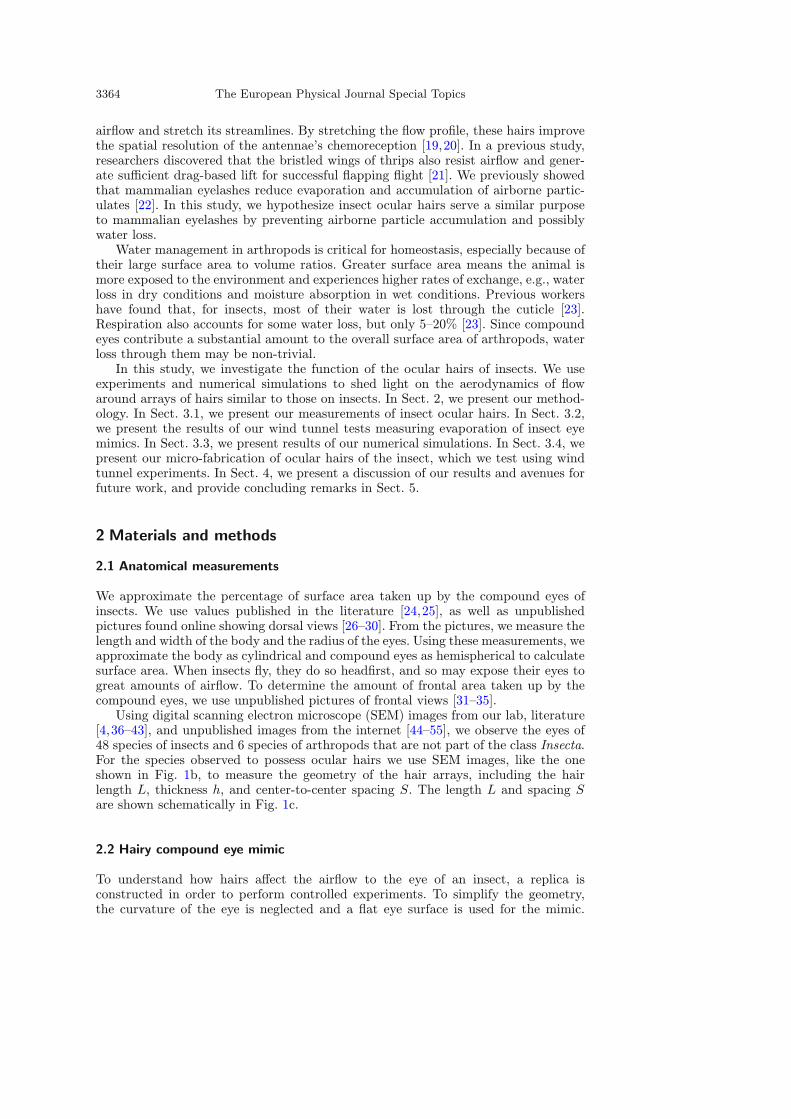
Wind tunnel experiments are conducted to determine how the presence of compoundeye hairs affects airflow at the eye surface. In these experiments, we measure how theevaporation rate m of a small dish of water is affected by an array of hairs similarto those found on fruit flies and moths. A schematic representing our experimentsis shown in Fig. 4a. The fluid mechanics between insect hairs is dictated by a localReynolds number Re based on the spacing S between the hairs and the flight speedU of the insects, found in previous literature [56,57,75–78]. The range of Reynoldsnumbers Re of the flows encountered by the insects comprising the data in Fig. 1dis Re = 0.31–150, from a midge to a moth. For our experiments, we use Re = 9 and150 to represent the dynamic range of values experienced by flying insects, from lowto moderate inertial effects.The results in Fig. 4b show how the the normalized hair length L/S affects the
normalized evaporation rate m. We normalize evaporation rate m with respect to thevalues for an eye without hairs L/S = 0. The blue and red crosses represent experi-ments for Reynolds numbers Re of 9 and 150, respectively. They span the dynamicregime of low to moderate Reynolds numbers represented by the insects studied.These results show that airflow at the ocular surface is greatly affected by the pres-ence of hairs.
3370 The European Physical Journal Special Topics
0 0.5 1 1.5
0
0.5
1
1.5 = 5 deg = 10 deg
0 2 4 6
0
0.5
1
1.5Experiments, Re = 9Simulation, Re = 9Brinkman’s modelExperiments, Re = 150Simulation, Re = 150
L / S
(b)
(d)
∆P
L / S
(a)
Ptop
Pbottom
∆P = Ptop - Pbottom
(c)
L
S
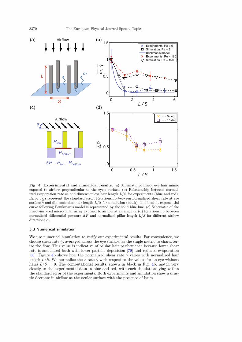
Fig. 4. Experimental and numerical results. (a) Schematic of insect eye hair mimicexposed to airflow perpendicular to the eye’s surface. (b) Relationship between normal-ized evaporation rate m and dimensionless hair length L/S for experiments (blue and red).Error bars represent the standard error. Relationship between normalized shear rate at eyesurface γ and dimensionless hair length L/S for simulation (black). The best-fit exponentialcurve following Brinkman’s model is represented by the solid blue line. (c) Schematic of theinsect-inspired micro-pillar array exposed to airflow at an angle α. (d) Relationship betweennormalized differential pressure ∆P and normalized pillar length L/S for different airflowdirections α.
3.3 Numerical simulation
We use numerical simulation to verify our experimental results. For convenience, wechoose shear rate γ, averaged across the eye surface, as the single metric to character-ize the flow. This value is indicative of ocular hair performance because lower shearrate is associated both with lower particle deposition [79] and reduced evaporation[80]. Figure 4b shows how the normalized shear rate γ varies with normalized hairlength L/S. We normalize shear rate γ with respect to the values for an eye withouthairs L/S = 0. The computational results, shown in black in Fig. 4b, match veryclosely to the experimental data in blue and red, with each simulation lying withinthe standard error of the experiments. Both experiments and simulation show a dras-tic decrease in airflow at the ocular surface with the presence of hairs.
Dynamics of Animal Systems 3371
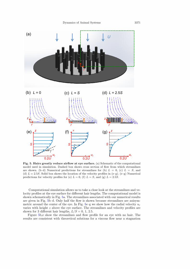
Fig. 5. Hairs greatly reduce airflow at eye surface. (a) Schematic of the computationalmodel used in simulation. Dashed box shows cross section of flow from which streamlinesare shown. (b–d) Numerical predictions for streamlines for (b) L = 0, (c) L = S, and(d) L = 2.5S. Solid box shows the location of the velocity profiles in (e–g). (e–g) Numericalpredictions for velocity profiles for (e) L = 0, (f) L = S, and (g) L = 2.5S.
Computational simulation allows us to take a close look at the streamlines and ve-locity profiles at the eye surface for different hair lengths. The computational model isshown schematically in Fig. 5a. The streamlines associated with our numerical resultsare given in Fig. 5b–d. Only half the flow is shown because streamlines are axisym-metric around the center of the eye. In Fig. 5e–g we show how the radial velocity urvaries with height z above the eye surface. The streamlines and velocity profiles areshown for 3 different hair lengths, L/S = 0, 1, 2.5.Figure 5b,e show the streamlines and flow profile for an eye with no hair. The
results are consistent with theoretical solutions for a viscous flow near a stagnation
3372 The European Physical Journal Special Topics
point, where successive streamlines veer horizontally as they approach the eye [81].Cross-sections of flow have a nearly parabolic velocity profile. The slope of the dashedline indicates the inverse of the shear rate γ at the ocular surface, and dictates theshear force exerted onto the eye surface.When hairs are added to the eye surface, both the streamlines and velocity profile
are changed drastically. For hair length L/S = 1, we observe the bulk of the flowveering horizontally before it gets close to the eye surface, as shown by Fig. 5c,f. Asshown in the velocity profile, there is much less air traveling immediately above theeye surface. This decrease in airflow results in a decrease in shear rate γ. As the hairsbecome longer the flow is turned away farther away from the eye surface, as shownby Fig. 5d,g. However, this only results in a slight reduction in shear rate since thepresence of hairs, regardless of length, creates a stagnant zone of air between the hairsand immediately above the eye surface. The transition to the freestream bulk flow isshifted away from the eye with increased hair length, but this does not greatly affectthe profile at the eye surface, as evidenced by comparing Fig. 5f,g.
3.4 Synthetic micro-pillars divert airflow
The diversion of airflow observed for the ocular hairs of insects may inform designsthat help keep man-made equipment free from airborne particle deposition. Syntheticstructures mimicking insect ocular hairs could be implemented on the sensitive sur-faces of equipment like sensors. In turn, we determine if synthetic, hair-like structurescan also divert airflow to protect surfaces.Following the fabrication procedure outlined in Sect. 2.5, we create multiple micro-
pillar arrays with piezo-resistive cantilever airflow sensors. By placing them in a smallwind tunnel, we test the effects of pillar length L, pillar spacing S, and wind directionα on the pressure difference ∆P imposed by the incoming flow, as defined in Fig. 4c.In Fig. 4d, we see that the differential pressure ∆P decreases as pillars increasein length L/S. The trend is similar to that measured in previous experiments andsimulations in Fig. 4b. However, with these experiments we can measure the effect ofhairs on nearly horizontal (α = 5 deg) flows. Using these microfabrication techniques,we can also test lengths below L/S = 1, which is the lower limit of our insect eyemimics in Fig. 2a. From our results, we see that even at a flow direction of α = 5 thehairs prevent airflow from reaching the surface. A reduction in differential pressureof 50% is observed for lengths of L/S ≥ 0.5.
4 Discussion
In this study, we investigated a passive mechanism to maintain the cleanliness ofcompound eyes. Wind tunnel experiments and numerical simulation were used to de-termine the effects of insect eye hairs on the incoming airflow. In both experimentsand simulation, the presence of hairs drastically decreased airflow at the eye surface,evidenced by a decrease in evaporation rate and shear rate, respectively. While theinsect eye is not wet, measuring evaporation rate provides a metric for the shear rateimposed by the surrounding airflow. When air flows over water, the shear forces atthe interface cause the water to evaporate. The evaporation rate is directly relatedto the shear rate [80]. Decreases in shear rate are attributed to decreases in parti-cle deposition velocity [79]; therefore, the presence of hairs help to reduce particledeposition onto the surface of the compound eye.From our wind tunnel experiments, represented by the blue and red crosses in
Fig. 4b, we see that the presence of hairs decreases the evaporation rate by up to 90%.

Dynamics of Animal Systems 3373
A previous study found that decreased rates of evaporation using a similarexperimental technique coincided with decreased rates in particle deposition [22].Similarly, numerical simulations, represented by the black open points in Fig. 4b,show that there is a drastic decrease in airflow with the presence of hair, especiallyfor the lower Reynolds number flow experienced by the fruit fly. The array of hairsprovide a resistance to the incoming airflow and divert it away from the surface ofthe eye. This effect is similar to what has been found to occur for the antennae of theluna and silkworm moths [19,20] and the bristled wings of thrips [21].Previous work by Brinkman [82] and Larson & Higdon [83] find that the velocity
of a fluid as it enters an infinite array of cylinders parallel to the flow decreases expo-nentially with penetration depth. The decay of evaporation and shear rate observedfor the low Reynolds number Re = 9 in Fig. 4b approximately follows an exponentialdecay. The exponential curve of best-fit for the experimental data, represented by thesolid blue line in Fig. 4b, has a coefficient of determination R2 = 0.97. The theoryderived by Brinkman is for a viscous flow with a low Reynolds number, or Stokesflow, so it agrees well with our data for Re = 9. Therefore, the arrayed hairs, just likecylinders, reduce the amount of flow reaching the eye surface.From our evaporation experiments and numerical simulation in Fig. 4b, we find
that hair-like structures protect the ocular surface from airflows perpendicular tothe ocular surface, while results from experiments with our synthetic micro-pillars inFig. 4d show that they can also protect from near parallel flows. Since the surface ofan insect’s eye is curved, different sections of the eye will experience flows perpendic-ular and parallel to the surface. Thus, ocular hairs protect the insect’s eye from flowsboth perpendicular and parallel to the eye surface.From anatomical measurements in Fig. 1d, hair length appears to be consistent
with spacing, even as the length varies across an order of magnitude. Our previousstudy found that eyelashes of an optimal length reduce tear film evaporation anddeposition [22]. Unlike the circumferential array of hair found in eyelashes, the in-terspersed array on the compound eye of insects does not have an optimal length.Beyond L = S, the evaporation and shear rate remain constant. Therefore, the insectspecies with L > S do not experience greater reductions in airflow at the eye surface.A possible advantage to longer hair is the increase in potential storage energy for cat-apulting deposited particles off [24]. The honey bee, an insect species that on averageencounters up to five times its body mass in pollen per day [78], has L = 3.4S. Theselong ocular hairs more closely resemble the lengths found throughout the rest of thebody.We have found that protection against airborne particles may be one potential
function for ocular hairs. In addition, these hairs could be multi-functional. Severalprevious workers found these hairs to be mechanosensory [4,7–9]. In honey bees theymay be involved in sensing airflow and aiding in flight control [7,8]. While in cricketsthey serve as triggers for eye and head grooming [9]. Upon close inspection of theinsect species possessing ocular hairs in Table 1, we notice that 13 of the 18 speciesare confirmed pollinators or flower visitors. Pollen collected directly from plants has athin, viscous layer of fluid called pollenkitt [84]. This sticky fluid attracts pollinatinginsects to the pollen grains through odor and provides capillary adhesion so the grainsremain attached to the insect. The ocular hairs may provide extra surface area forthe pollenkitt to adhere to, as well as suspend pollen away from the surface for easierremoval.In our experiments and simulations we use stiff members to represent the in-
sect ocular hairs. We find the ocular hairs are effectively rigid when exposed to flowassociated with the Reynolds number of the fruit fly and forage looper moth during
flight. The ratio of viscous to elastic forces [85] is 256µL3UEh4 ln ( 2Lh )
∼ 10−3–10−2, where
3374 The European Physical Journal Special Topics
µ is the dynamic viscosity of air and E = 3.05GPa is the modulus of elasticity of
insect cuticle [86]; the ratio of inertial and elastic forces [87] is ρU2L3
Eh3 ∼ 10−5–10−4,
indicating typical air flow has a negligible effect on hair deflection. Here, we assumethe hair is rigidly attached at the base. However, sensory hairs have flexible basesthat allow them to pivot and deform the anchoring tissue. Special cells located atthe base behave like strain sensors and can quantify the hairs deflection based on thetissues deformation. These hairs are therefore capable of measuring forces. The flexi-bility of the base can be tuned to measure airflow, as has been found for crickets andspiders [88].We successfully fabricated pillar arrays of the same scale as those found on the
compound eyes of insects. However, we found that there were some limitationsto our wind tunnel experiments. In particular, for nearly perpendicular airflows(α = 90 deg), the sensor would always read the same differential pressure ∆P .However, for nearly horizontal flows (α = 5 deg), the sensor reads differences inthe differential pressure ∆P , as expected. We believe that for normally impingingflows, the sensors read the dynamic pressure of the freestream flow, rather than thelocal flows on the surface and in between the pillars because dynamic pressure dom-inates over form drag for blunt objects. On the other hand, for near shearing flows,the sensors bend in response to the pressure from the local airflow. We also foundthat both of the airflow sensors read the same pressure difference ∆P , even thoughone is in between the pillars and the other is directly underneath one of the pillars.Therefore, the differential pressure ∆P across the surface dominates over the pressureexerted onto the pillars.Future studies should be pursued to directly measure the number of airborne
particle impacting a surface with hair arrays. The experiments could follow thosepreviously conducted by the authors [89]. In these experiments, a microcantileverwas used to measure the number of particles impacting the sensor when exposed toa particle-laden flow. Hair arrays could be fabricated onto the surface of the micro-cantilever to see if there is a reduction in the number of particle impacts.With future technologies, this study on micro-cleaning mechanisms can lead to
bio-inspired designs aimed at maintaining micro-electronic devices clean. Devices suchas Micro Aerial Vehicles (MAVs), microelectromechanical systems (MEMS), camerasensors and lenses, and solar panels may encounter harmful micro-scale particles dur-ing their use, and would benefit from efficient passive cleaning mechanisms to reducemalfunctions.
5 Conclusion
In this study, we investigated the function of the ocular hairs of insects. We per-formed a combination of wind tunnel experiments, numerical simulation and micro-fabrication of at-scale insect ocular hairs. We observed a minority of insects possessocular hairs, but among those that do, hair length is equal to hair spacing. Wind tun-nel experiments and computational fluid simulations find that this hair length pro-vides reduction of airflow of 90% when air impinges the eye surface normally. Greaterhair lengths provide diminishing returns for reduction of airflow. Experiments withour micro-fabricated ocular hairs show that 50% reduction of airflow occurs for shearflow, air traveling parallel to the eye surface. A reduction of flow is accompanied byreduction of particle deposition. Structures inspired by the ocular hairs may be usefulin protecting the sensitive surfaces of sensors in order to help extend their usable life.
We thank F. Chen for his early contributions, and financial support of the NSF (PHY-1255127, CBET-1256403, and EAPSI-1415032) and the Japanese Society for the Promotion
Dynamics of Animal Systems 3375
of Science (JSPS) during the East Asia and Pacific Summer Institute (EAPSI) 2014. Thisstudy was partly supported by JSPS KAKENHI Grant Number 25000010. The EB photomask fabrication was performed using the EB lithography apparatus at the VLSI Designand Education Center (VDEC) at the University of Tokyo.
References
1. M.V. Srinivasan, S. Zhang, Ann. Rev. Neurosci. 27, 679 (2004)2. L.F. Tammero, M.H. Dickinson, J. Exper. Biol. 205, 2785 (2002)3. A. Sourakov, Florida Entomologist 94, 367 (2011)4. H. Hinton, Roy Entomol. Soc. London Symp. (1970)5. M.F. Land, R.D. Fernald, Ann. Rev. Neurosci. 15, 1 (1992)6. W.H. Miller, G.D. Bernard, J.L. Allen, Science 162, 760 (1968)7. V. Neese, Z. Vergleichende Physiol. 49, 543 (1965)8. V. Neese, Z. Vergleichende Physiol. 52, 149 (1966)9. H.-W. Honegger, Cell Tissue Res. 182, 281 (1977)10. M.M. Perry, J. Morphol. 124, 249 (1968)11. F.G. Barth, Curr. Opin. Neurobiol. 14, 415 (2004)12. J. Casas, T. Steinmann, G. Krijnen, J. Royal Soc. Interface 7, 1487 (2010)13. R. Fettiplace, C.M. Hackney, Nat. Rev. Neurosci. 7, 19 (2006)14. A. Bejan, J. Heat Transfer (Transactions ASME, Ser. C) 112, 662 (1990)15. A. Battisti, G. Holm, B. Fagrell, S. Larsson, Ann. Rev. Entomol. 56, 203 (2011)16. M.S. Mooring, W.M. Samuel, Behaviour 135, 693 (1998)17. D.I. Rubenstein, M. Koehl, Am. Naturalist 981 (1977)18. M. Lippmann, D. Yeates, R. Albert, Br. J. Ind. Med. 37, 337 (1980)19. S. Vogel, J. Insect Physiol. 29, 597 (1983)20. C. Loudon, E.C. Davis, J. Chem. Ecol. 31, 1 (2005)21. K. Sato, H. Takahashi, M.-D. Nguyen, K. Matsumoto, I. Shimoyama, 2013 IEEE 26thInternational Conference on Micro Electro Mechanical Systems (MEMS), 21 (2013)
22. G.J. Amador, et al., J. Royal Soc. Interface 12, 20141294 (2015)23. J.B. Benoit, Aestivation (publisher Springer, 2010), p. 20924. G.J. Amador, D.L. Hu, J. Exper. Biol. 218(20), 3164 (2015)25. M. Streinzer, A. Brockmann, N. Nagaraja, J. Spaethe, PloS One 8, 57702 (2013)26. Diptera.info. Chrysotoxum elegans. http://www.diptera.info/forum/attachments/img-0837 1.jpg
27. A. Karawath, User:Aka/Images/Animals. https://commons.wikimedia.org/wiki/User:Aka/Images/Animals
28. D. Coetzee, https://commons.wikimedia.org/wiki/File:Lucilia sericata ondoorknob - detail of fly.jpg
29. L. Howard, http://remf.dartmouth.edu/images/insectPart3SEM/30. Alamy, http://www.alamy.com/stock-photo-gnat-culex-pipiens-the-common-house-mosquito-top-dorsal-view-51307101.html
31. A. Cockburn, http://www.tirpor.com/cpg public/32. P. Waters, http://www.shutterstock.com/pic-77748943/stock-photo-western-honey-bee-in-flight-with-sharp-focus-on-its-head-isolated-on-white.html?src=tQhZhOTnaTzj6X4vDyIFrA-1-24
33. Karlsson, C. Musca domestica @ 5X. https://www.flickr.com/photos/conkar/6792723054/
34. Diptera.info. Chrysotoxum intermedium. http://www.diptera.info/forum/attachments/ev-chrysotoxum-intermedium.jpg
35. wiseGEEK. http://www.wisegeekhealth.com what-is-an-occipital-lymph-node.htm#very-close-view-of-mosquito-on-human-skin
36. A.R. Parker, Z. Hegedus, R.A. Watts, Proc. Royal Soc. London. Series B: Biol. Sci. 265,811 (1998)
37. S.D. Carlson, C. Chi, Cell Tissue Res. 149, 21 (1974)

3376 The European Physical Journal Special Topics
38. D.G. Stavenga, S. Foletti, G. Palasantzas, K. Arikawa, Proc. Royal Soc. B: BiologicalSci. 273, 661 (2006)
39. A. Oliva, A new species Oxelytrum Gistel (Coleoptera, Silphidae) from southernArgentina, with a key to the species genus. ZooKeys 1 (2012)
40. S. Fischer, C.H. Mueller, V.B. Meyer-Rochow, Visual Neurosci. 28, 295 (2011)41. M.W. Szyndler, K.F. Haynes, M.F. Potter, R.M. Corn, C. Loudon, J. Royal Soc.Interface 10, 20130174 (2013)
42. T. Bourguignon, Y. Roisin, ZooKeys, 55 (2011)43. S. Zonstein, Y.M. Marusik, (Araneae, Palpimanidae) ZooKeys, 27 (2013)44. G.S. Paulson, http://webspace.ship.edu/gspaul45. M. Smith, Part III – Human Eyes and Insect Eyes: A 3D modelling article.http://www.microscopy-uk.org.uk/mag/artjun10/mol%-eyes1.html
46. A. Osterrieder, http://www.plantcellbiology.com 2012 0247. California Department Food Agriculture Novakia miloi kerr http://www.cdfa.ca.gov/plant/ppd/Lucid/Novakia/key/Novakia/Media/Html/N miloi.htm
48. The University Virginia Virtual Lab. http://www.virlab.virginia.edu/nanoscienceclass Nanoscience class.htm Lab
49. D. Gregory, D. Marshall, http://wellcomeimages.org/indexplus/image/B0000664.html
50. The University Texas at Dallas Department Geosciences. https://www.utdallas.edu/ pujana/sem/ant1.htm.
51. Euchoo. Boliaology Part 01. http://euchoo.net/blog.bk/Boliaology-Part0152. Biology Department at Swarthmore College. The Robert Savage Image Award AtSwarthmore College. https://savageimageaward.wordpress.com/
53. Gans, M. http://murry-gans.blogspot.com/2012 12 01 archive.html54. Howard, L. Insect Part 1 SEM. http://remf.dartmouth.edu/images/insectPart1SEM/55. Midwood Sci. SEM. http://midwoodscience.org/sem/2012/56. S. Vogel, J. Exper. Biol. 44, 567 (1966)57. H. Davies, C.A. Butler (Rutgers University Press, 2008)58. S. Succi (Oxford University Press, 2001)59. C.K. Aidun, J.R. Clausen, Ann. Rev. Fluid Mech. 42, 439 (2010)60. A.J.C. Ladd, R. Verberg, J. Statist. Phys. 104, 1191 (2001)61. Z.G. Mills, W. Mao, A. Alexeev, Trends BioTechnol. 31, 246 (2013)62. E. Gauger, H. Stark, Physical Rev. E 74 (2006)63. H. Jian, A.V. Vologodskii, T. Schlick, J. Comp. Phys. 136, 168 (1997)64. C.S. Peskin, Acta Numerica 11, 479 (2002)65. M. Bouzidi, M. Firdaouss, P. Lallemand, Phys. Fluids 13, 3452 (2001)66. R. Ghosh, G.A. Buxton, O.B. Usta, A.C. Balazs, A. Alexeev, Langmuir 26, 2963 (2009)67. J. Branscomb, A. Alexeev, Soft Matter 6, 4066 (2010)68. C. Semmler, A. Alexeev, Phys. Rev. E 84, 066303 (2011)69. Z.G. Mills, B. Aziz, A. Alexeev, Soft Matter 8, 11508 (2012)70. H. Takahashi, N.M. Dung, K. Matsumoto, I. Shimoyama, J. Micromech. Microeng. 22,055015 (2012)
71. H. Takahashi, K. Matsumoto, I. Shimoyama, Measur. Sci. Technol. 24, 055304 (2013)72. M. Gel, I. Shimoyama, J. Micromech. Microeng. 14, 423 (2004)73. N. Thanh-Vinh, H. Takahashi, K. Matsumoto, I. Shimoyama, Sensors Actuators A:Physical (2014)
74. C. Chi, S.D. Carlson, Cell Tissue Res. 166, 353 (1976)75. L. Sedda, et al., Proc. Royal Soc. B: Biological Sci. 279, 2354 (2012)76. J.H. Fewell, Behavioral Ecol. Sociobiol. 22, 401 (1988)77. M.W. Davidson, http://micro.magnet.fsu.edu/optics/olympusmicd/galleries/darkfield/muscadomestica1.html
78. M.L. Winston, The Biology of the honey bee (Harvard University Press, 1991)79. T. Schneider, M. Bohgard, Indoor Air 15, 215 (2005)

Dynamics of Animal Systems 3377
80. T.L. Bergman, F.P. Incropera, A.S. Lavine, D.P. DeWitt, Fundamentals Heat and MassTransfer (John Wiley, Sons, 2011)
81. H. Schlichting, K. Gersten, Boundary-layer theory (Springer, 2000)82. H. Brinkman, Appl. Scientific Res. 1, 27 (1949)83. R. Larson, J. Higdon, J. Fluid Mech. 166, 449 (1986)84. E. Pacini, M. Hesse, Flora-Morphology, Distribution, Funct. Ecol. Plants 200, 399 (2005)85. L. Guglielmini, A. Kushwaha, E.S. Shaqfeh, H.A. Stone, Phys. Fluids 24, 123601 (2012)86. J.-H.Dirks, D. Taylor, J. Exper. Biol. 215, 1502 (2012)87. E. De Langre, Ann. Rev. Fluid Mech. 40, 141 (2008)88. J.A. Humphrey, F.G. Barth, Adv. Insect Physiol. 34, 1 (2007)89. H. Takahashi, T. Kan, K. Matsumoto, I. Shimoyama, IEEE Inter. Conf. Micro ElectroMech. Sys. (MEMS) (in preparation)