Embed Size (px)
Citation preview
Bulletin No. 2005
Best-selling range of bore gages now offers better accuracy, user-friendliness and durability
Small Tool Instruments and Data Management
Inside Diameter Measurement Bore Gage
NEW
111
222
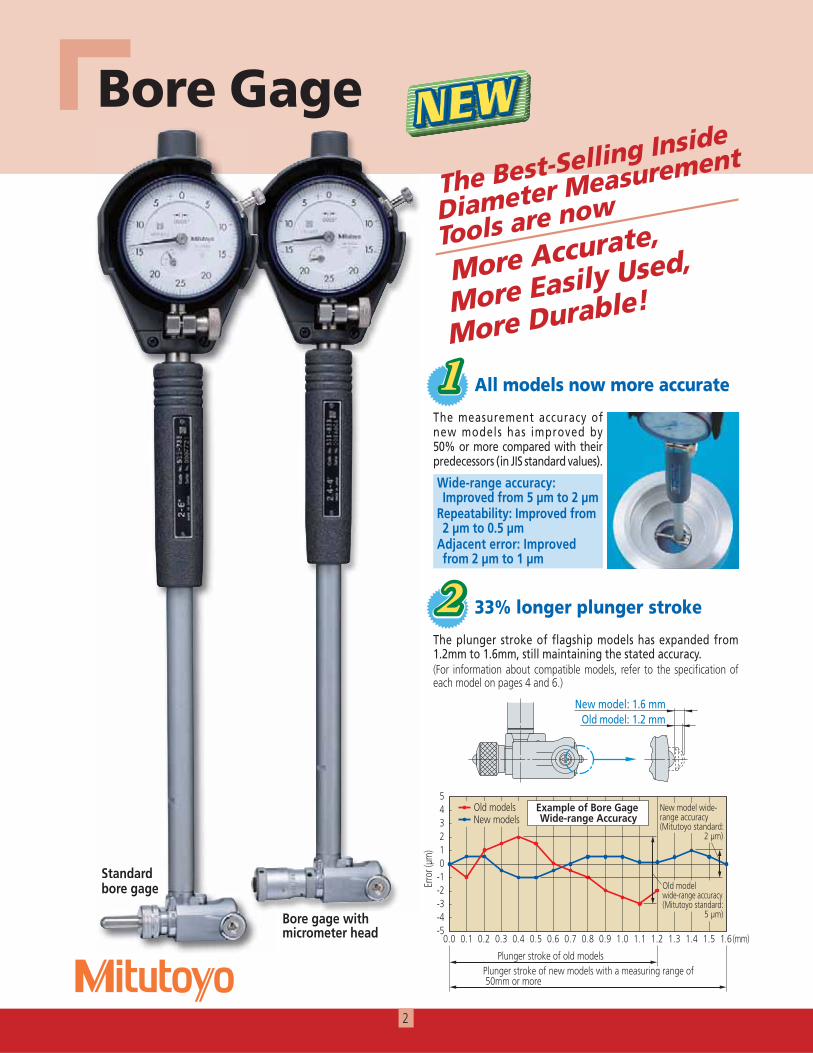
Wide-range accuracy: Improved from 5 μm to 2 μm
Repeatability: Improved from 2 μm to 0.5 μm
Adjacent error: Improved from 2 μm to 1 μm
The plunger stroke of flagship models has expanded from 1.2mm to 1.6mm, still maintaining the stated accuracy.(For information about compatible models, refer to the specification of each model on pages 4 and 6.)
The Best-Selling Inside
Diameter Measurement
Tools are now
More Accurate,
More Easily Used,
More Durable!
2
All models now more accurate
33% longer plunger stroke
Standard bore gage
Bore gage with micrometer head
NEW
The measurement accuracy of new models has improved by 50% or more compared with their predecessors (in JIS standard values).
Bore Gage
Standard bore gage
333
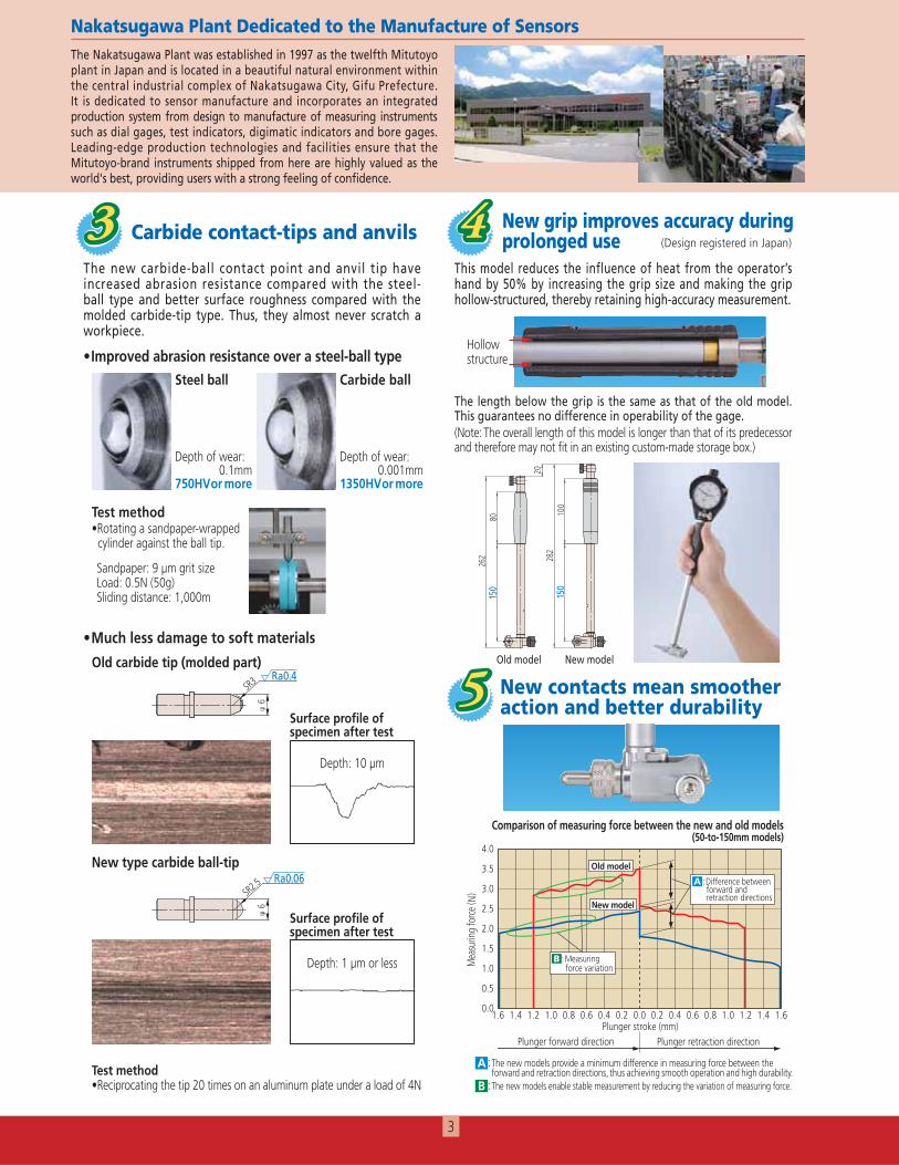
Much less damage to soft materials
The new carbide-ball contact point and anvil tip have increased abrasion resistance compared with the steel-ball type and better surface roughness compared with the molded carbide-tip type. Thus, they almost never scratch a workpiece.
3
φ6
SR3 Ra0.4
φ6
SR2.5 Ra0.06
Carbide contact-tips and anvils
The Nakatsugawa Plant was established in 1997 as the twelfth Mitutoyo plant in Japan and is located in a beautiful natural environment within the central industrial complex of Nakatsugawa City, Gifu Prefecture. It is dedicated to sensor manufacture and incorporates an integrated production system from design to manufacture of measuring instruments such as dial gages, test indicators, digimatic indicators and bore gages. Leading-edge production technologies and facilities ensure that the Mitutoyo-brand instruments shipped from here are highly valued as the world's best, providing users with a strong feeling of confidence.
444This model reduces the influence of heat from the operator’s hand by 50% by increasing the grip size and making the grip hollow-structured, thereby retaining high-accuracy measurement.
The length below the grip is the same as that of the old model. This guarantees no difference in operability of the gage. (Note: The overall length of this model is longer than that of its predecessor and therefore may not fit in an existing custom-made storage box.)
262 28
220
150
80
150
100
New grip improves accuracy during prolonged use (Design registered in Japan)
Test method
cylinder against the ball tip.
Sandpaper: 9 μm grit size Load: 0.5N (50g) Sliding distance: 1,000m
Steel ball Carbide ball
Test method
Old carbide tip (molded part)
New type carbide ball-tip
Improved abrasion resistance over a steel-ball type
Surface profile of specimen after test
Depth: 10 μm
Surface profile of specimen after test
Depth: 1 μm or less
Nakatsugawa Plant Dedicated to the Manufacture of Sensors
structure
Old model New model
0.1mm750HV or more
0.001mm1350HV or more
555 New contacts mean smoother action and better durability
A : and retraction directions, thus achieving smooth operation and high durability.
B :
Comparison of measuring force between the new and old models (50-to-150mm models)
4
Series 511Standard Bore Gage
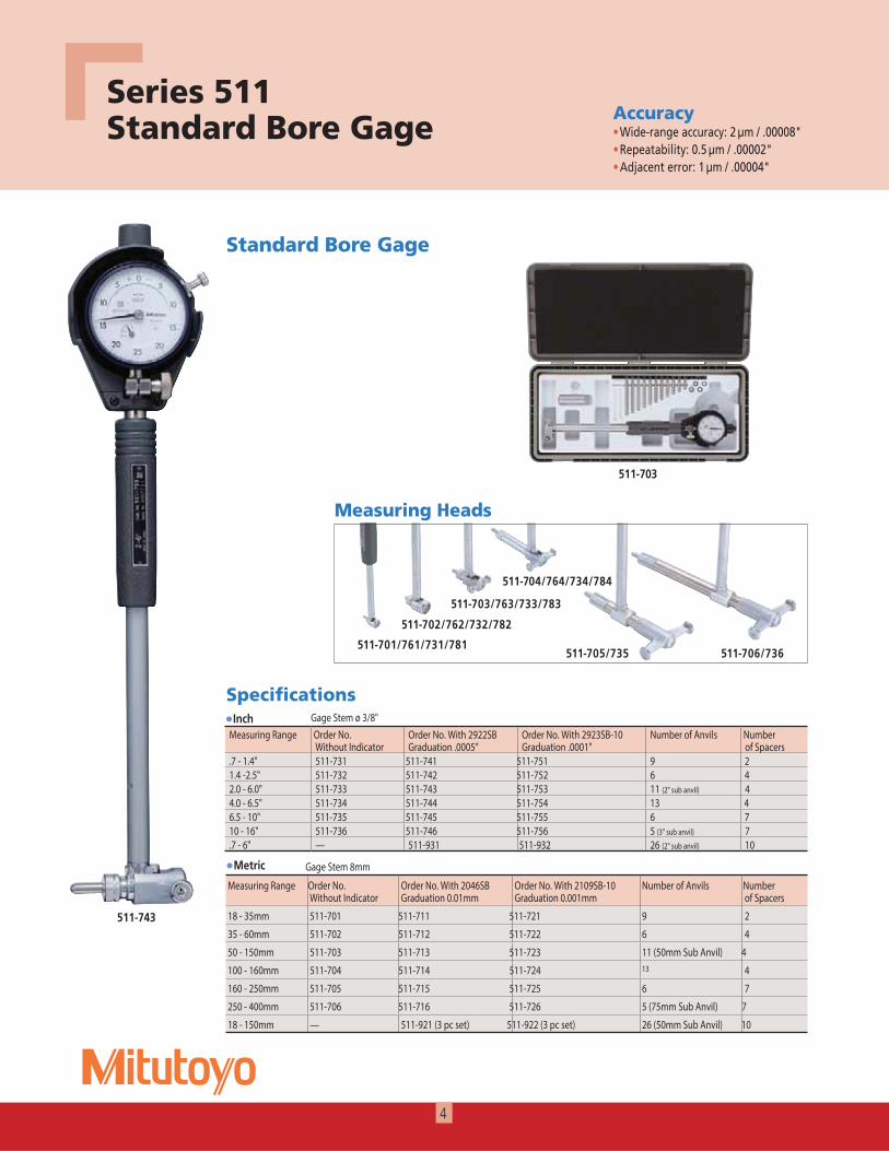
Standard Bore Gage
AccuracyWide-range accuracy: 2 µm / .00008"Repeatability: 0.5 µm / .00002"Adjacent error: 1 µm / .00004"
Metric
Specifications
Measuring Heads
511-701/761/731/781
511-702/762/732/782
511-705/735
511-703/763/733/783
511-704/764/734/784
511-706/736
511-703
511-743
Inch
Measuring Range Order No.Without Indicator
Order No. With 2046SB Graduation 0.01mm
Order No. With 2109SB-10 Graduation 0.001mm
Number of Anvils Number of Spacers
18 - 35mm 511-701 511-711 511-721 29
35 - 60mm 511-702 511-712 511-722 46
50 - 150mm 511-703 511-713 511-723 11 (50mm Sub Anvil) 4
100 - 160mm 511-704 511-714 511-724 13 4
160 - 250mm 511-705 511-715 511-725 76
250 - 400mm 511-706 511-716 511-726 5 (75mm Sub Anvil) 7
18 - 150mm — 511-921 (3 pc set) 511-922 (3 pc set) 26 (50mm Sub Anvil) 10
Measuring Range Order No.Without Indicator
Order No. With 2922SB Graduation .0005”
Order No. With 2923SB-10 Graduation .0001"
Number of Anvils Number of Spacers
.7 - 1.4" 511-731 511-741 511-751 9 21.4 -2.5" 511-732 511-742 511-752 6 42.0 - 6.0" 511-733 511-743 511-753 11 (2" sub anvil) 44.0 - 6.5" 511-734 511-744 511-754 13 46.5 - 10" 511-735 511-745 511-755 6 710 - 16" 511-736 511-746 511-756 5 (3" sub anvil) 7.7 - 6" — 511-931 511-932 26 (2" sub anvil) 10
Gage Stem ø 3/8"
Gage Stem 8mm
5
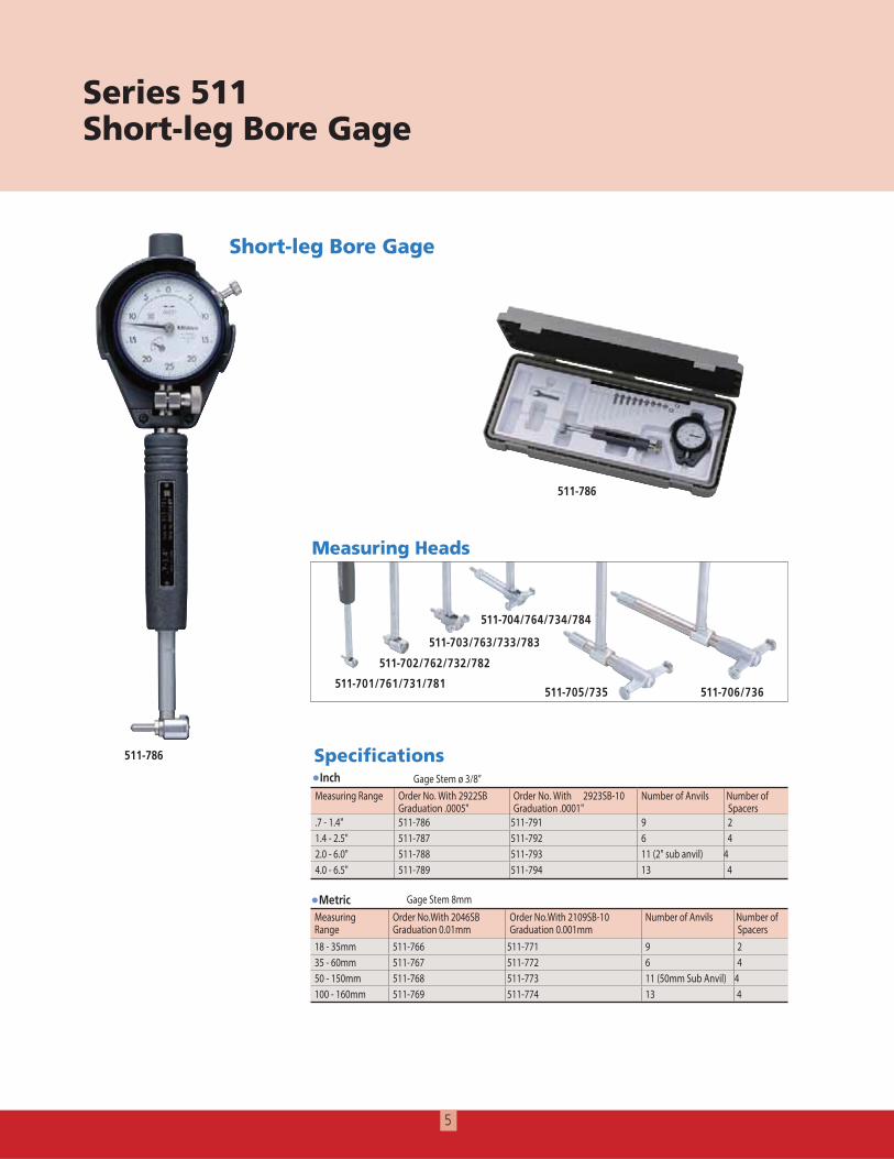
Short-leg Bore Gage
511-786
511-786
Metric
Inch
MeasuringRange
Order No.With 2046SB Graduation 0.01mm
Order No.With 2109SB-10 Graduation 0.001mm
Number of Anvils Number of Spacers
18 - 35mm 511-766 511-771 9 235 - 60mm 511-767 511-772 6 450 - 150mm 511-768 511-773 11 (50mm Sub Anvil) 4100 - 160mm 511-769 511-774 13 4
Measuring Range Order No. With 2922SB Graduation .0005"
Order No. With 2923SB-10 Graduation .0001"
Number of Anvils Number of Spacers
.7 - 1.4" 511-786 511-791 9 21.4 - 2.5" 511-787 511-792 6 42.0 - 6.0" 511-788 511-793 11 (2" sub anvil) 44.0 - 6.5" 511-789 511-794 13 4
Gage Stem ø 3/8”
Series 511Short-leg Bore Gage
Measuring Heads
511-701/761/731/781
511-702/762/732/782
511-705/735
511-703/763/733/783
511-704/764/734/784
511-706/736
Specifications
Gage Stem 8mm
6
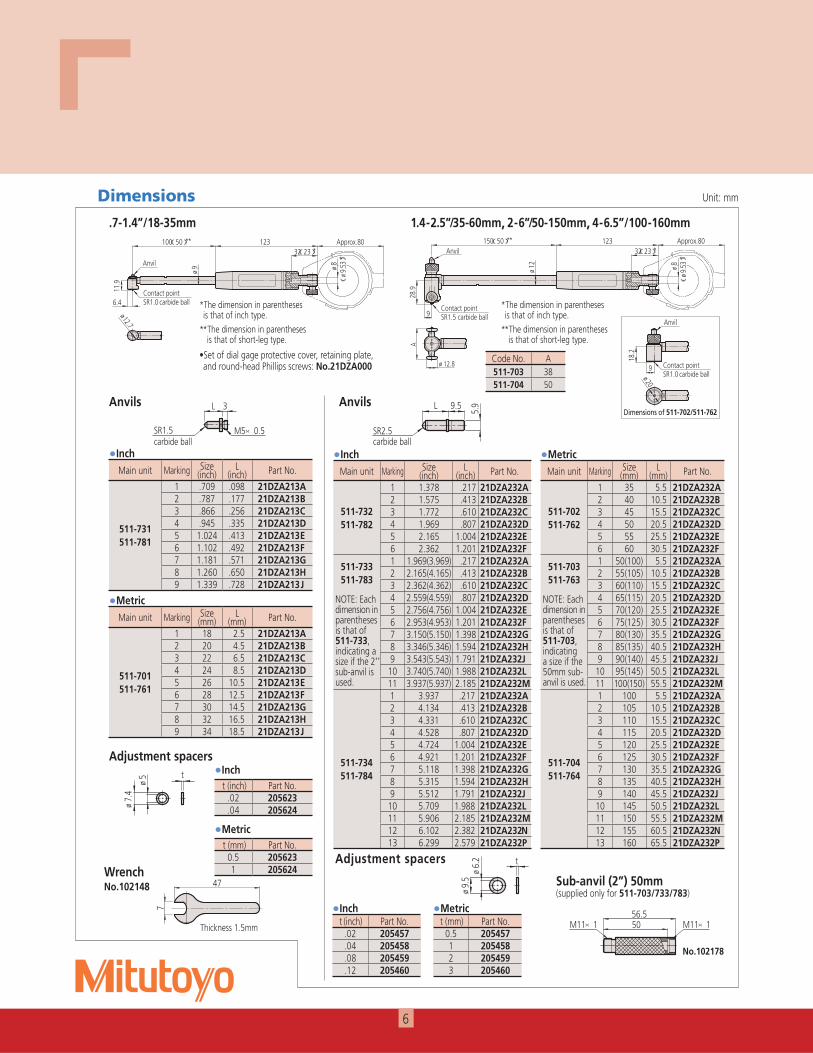
Dimensions Unit: mm
.7-1.4”/18-35mm( )
( )
ø ø(ø
)
ø
øø
Main unit Marking Size (mm)
L (mm) Part No.
511-701511-761
1 18 2.5 21DZA213A2 20 4.5 21DZA213B3 22 6.5 21DZA213C4 24 8.5 21DZA213D5 26 10.5 21DZA213E6 28 12.5 21DZA213F7 30 14.5 21DZA213G8 32 16.5 21DZA213H9 34 18.5 21DZA213J
Main unit Marking Size (inch)
L (inch) Part No.
511-731511-781
1 .709 .098 21DZA213A2 .787 .177 21DZA213B3 .866 .256 21DZA213C4 .945 .335 21DZA213D5 1.024 .413 21DZA213E6 1.102 .492 21DZA213F7 1.181 .571 21DZA213G8 1.260 .650 21DZA213H9 1.339 .728 21DZA213J
t (mm) Part No.0.5 2056231 205624
t (inch) Part No..02 205623.04 205624
1.4-2.5”/35-60mm, 2-6”/50-150mm, 4-6.5”/100-160mm( )
ø
511-702/511-762
ø
ø
( )
ø(ø
)
Code No. A511-703 38511-704 50
t (mm) Part No.0.5 2054571 2054582 2054593 205460
t (inch) Part No..02 205457.04 205458.08 205459.12 205460
Adjustment spacers
øø
No.102178
× ×
Main unit Marking Size (mm)
L (mm) Part No.
511-702511-762
1 35 5.5 21DZA232A2 40 10.5 21DZA232B3 45 15.5 21DZA232C4 50 20.5 21DZA232D5 55 25.5 21DZA232E6 60 30.5 21DZA232F
511-703511-763
1 50(100) 5.5 21DZA232A2 55(105) 10.5 21DZA232B3 60(110) 15.5 21DZA232C
NOTE: Each dimension in parentheses is that of 511-703, indicating a size if the 50mm sub-anvil is used.
4 65(115) 20.5 21DZA232D5 70(120) 25.5 21DZA232E6 75(125) 30.5 21DZA232F7 80(130) 35.5 21DZA232G8 85(135) 40.5 21DZA232H9 90(140) 45.5 21DZA232J10 95(145) 50.5 21DZA232L11 100(150) 55.5 21DZA232M
511-704511-764
1 100 5.5 21DZA232A2 105 10.5 21DZA232B3 110 15.5 21DZA232C4 115 20.5 21DZA232D5 120 25.5 21DZA232E6 125 30.5 21DZA232F7 130 35.5 21DZA232G8 135 40.5 21DZA232H9 140 45.5 21DZA232J10 145 50.5 21DZA232L11 150 55.5 21DZA232M12 155 60.5 21DZA232N13 160 65.5 21DZA232P
Main unit Marking Size (inch)
L (inch) Part No.
511-732511-782
1 1.378 .217 21DZA232A2 1.575 .413 21DZA232B3 1.772 .610 21DZA232C4 1.969 .807 21DZA232D5 2.165 1.004 21DZA232E6 2.362 1.201 21DZA232F
511-733511-783
1 1.969(3.969) .217 21DZA232A2 2.165(4.165) .413 21DZA232B3 2.362(4.362) .610 21DZA232C
NOTE: Each dimension in parentheses is that of 511-733, indicating a size if the 2” sub-anvil is used.
4 2.559(4.559) .807 21DZA232D5 2.756(4.756) 1.004 21DZA232E6 2.953(4.953) 1.201 21DZA232F7 3.150(5.150) 1.398 21DZA232G8 3.346(5.346) 1.594 21DZA232H9 3.543(5.543) 1.791 21DZA232J
10 3.740(5.740) 1.988 21DZA232L11 3.937(5.937) 2.185 21DZA232M
511-734511-784
1 3.937 .217 21DZA232A2 4.134 .413 21DZA232B3 4.331 .610 21DZA232C4 4.528 .807 21DZA232D5 4.724 1.004 21DZA232E6 4.921 1.201 21DZA232F7 5.118 1.398 21DZA232G8 5.315 1.594 21DZA232H9 5.512 1.791 21DZA232J
10 5.709 1.988 21DZA232L11 5.906 2.185 21DZA232M12 6.102 2.382 21DZA232N13 6.299 2.579 21DZA232P
Sub-anvil (2”) 50mm (supplied only for 511-703/733/783)
Adjustment spacers
Anvils
×
Anvils
**The dimension in parentheses is that of short-leg type.
*The dimension in parentheses is that of inch type.
**The dimension in parentheses is that of short-leg type.
*The dimension in parentheses is that of inch type.
Set of dial gage protective cover, retaining plate, and round-head Phillips scre s: No.21DZA000
WrenchNo.102148
7
47
厚さ1.5Thickness 1.5mm
Metric
Metric
Metric
MetricInch
Inch
Inch
Inch
t(mm) Part No.
0.5 2054671 2054612 2054623 2054634 2054645 2054656 205466
MetricMain unit Marking Size
(inch)L
(inch) Part No.
511-735
1 6.500 .394 21DZA241A2 7.091 .984 21DZA241B3 7.681 1.575 21DZA241C4 8.272 2.165 21DZA241D5 8.862 2.756 21DZA241E6 9.453 3.346 21DZA241F
511-736NOTE: Each dimension in parentheses is that of 511-736, indicating a size if the 3” sub-anvil is used.
1 10.000(13.000) .394 21DZA241A
2 10.591(13.591) .984 21DZA241B
3 11.181(14.181) 1.575 21DZA241C
4 11.772(14.772) 2.165 21DZA241D
5 12.362(15.362) 2.756 21DZA241E
Inch
7
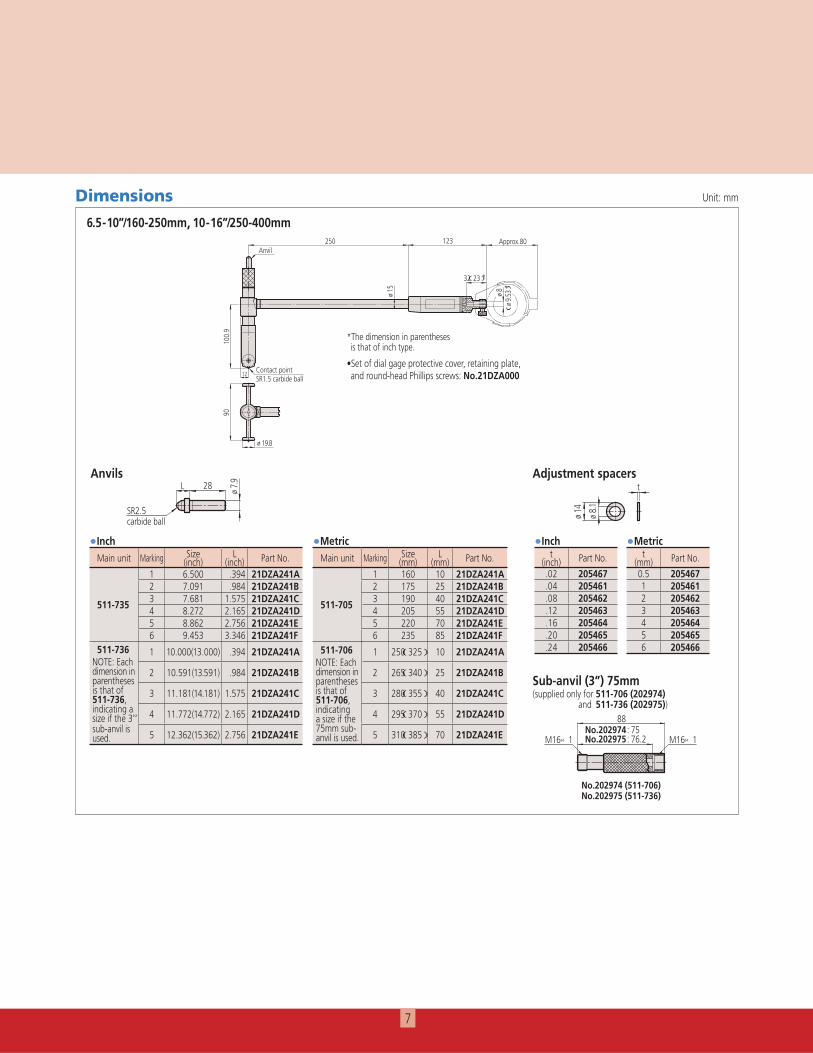
Dimensions Unit: mm
6.5-10”/160-250mm, 10-16”/250-400mm
ø
ø
( )
ø
(ø
)
øø
Adjustment spacersAnvils
ø
Main unit Marking Size (mm)
L (mm) Part No.
511-705
1 160 10 21DZA241A2 175 25 21DZA241B3 190 40 21DZA241C4 205 55 21DZA241D5 220 70 21DZA241E6 235 85 21DZA241F
511-706NOTE: Each dimension in parentheses is that of 511-706, indicating a size if the 75mm sub-anvil is used.
1 250(325) 10 21DZA241A
2 265(340) 25 21DZA241B
3 280(355) 40 21DZA241C
4 295(370) 55 21DZA241D
5 310(385) 70 21DZA241E
t(inch) Part No.
.02 205467
.04 205461
.08 205462
.12 205463
.16 205464
.20 205465
.24 205466
Set of dial gage protective cover, retaining plate, and round-head Phillips scre s: No.21DZA000
No.202974No.202975× ×
Sub-anvil (3”) 75mm (supplied only for 511-706 (202974)
and 511-736 (202975))
No.202974 (511-706) No.202975 (511-736)
Metric Inch
*The dimension in parentheses is that of inch type.
8
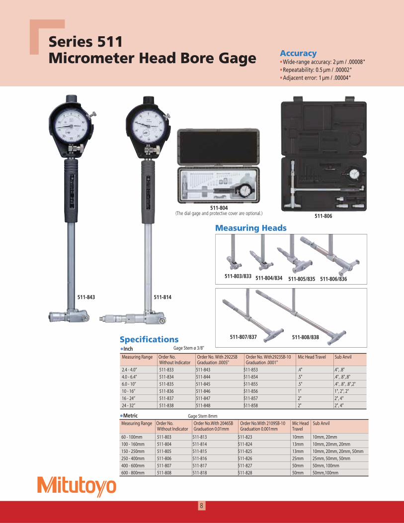
Series 511Micrometer Head Bore Gage
511-807/837 511-808/838
Measuring Heads
511-803/833 511-804/834 511-806/836511-805/835
418-115348-115
511-804 (The dial gage and protective cover are optional.) 511-806
AccuracyWide-range accuracy: 2 µm / .00008"Repeatability: 0.5 µm / .00002"Adjacent error: 1 µm / .00004"
Metric
SpecificationsInch
Measuring Range Order No. Without Indicator
Order No.With 2046SB Graduation 0.01mm
Order No.With 2109SB-10 Graduation 0.001mm
Mic Head Travel
Sub Anvil
60 - 100mm 511-803 511-813 511-823 10mm 10mm, 20mm100 - 160mm 511-804 511-814 511-824 13mm 10mm, 20mm, 20mm150 - 250mm 511-805 511-815 511-825 13mm 10mm, 20mm, 20mm, 50mm250 - 400mm 511-806 511-816 511-826 25mm 25mm, 50mm, 50mm400 - 600mm 511-807 511-817 511-827 50mm 50mm, 100mm600 - 800mm 511-808 511-818 511-828 50mm 50mm,100mm
Measuring Range Order No. Without Indicator
Order No. With 2922SB Graduation .0005"
Order No. With2923SB-10 Graduation .0001"
Mic Head Travel Sub Anvil
2.4 - 4.0” 511-833 511-843 511-853 .4" .4", .8"4.0 - 6.4” 511-834 511-844 511-854 .5" .4", .8",.8"6.0 - 10” 511-835 511-845 511-855 .5" .4", .8", .8",2"10 - 16” 511-836 511-846 511-856 1" 1", 2", 2"16 - 24” 511-837 511-847 511-857 2" 2", 4"24 - 32” 511-838 511-848 511-858 2" 2", 4"
Gage Stem ø 3/8"
Gage Stem 8mm
9
Code No. Part No.
511-803 301336(2piece) 202863(1piece)
511-804 301336(2piece)511-805 301336(2piece)511-806 200154(2piece)511-807 200154(2piece)511-808 200154(2piece)
Code No. Part No.
511-833 301336(2piece) 202863(1piece)
511-834 301336(2piece)511-835 301336(2piece)511-836 200154(2piece)511-837 200154(2piece)511-838 200154(2piece)
D
Bø
H
E
A 123 Approx.80
øG
FC
32(23)*
ø
8(ø 9
.53)
*
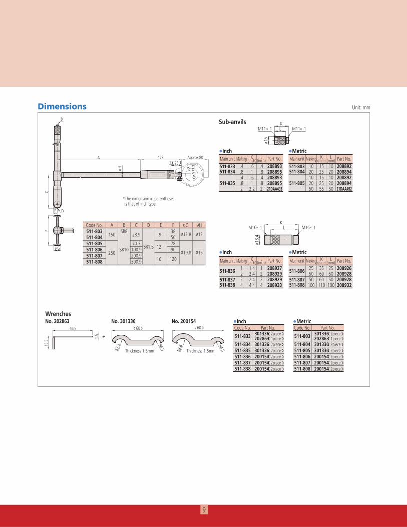
Code No. A B C D E F øG øH511-803
150S 8
28.9 938 ø12.8 ø12511-804 50
511-805 70.3S 1.5 12
78
ø19.8 ø15511-806250
S 10 100.9 90 511-807 200.9
16 120
511-808 300.9
Sub-anvils M11×1 M11×1
ø 15
KL
M16×1M16×1 LK
ø 18.
4Main unit Marking K
(mm)L
(mm) Part No.
511-806 25 35 25 20892650 60 50 208928
511-807511-808
50 60 50 208928100 110 100 208932
Main unit Marking K (inch)
L (inch) Part No.
511-836 1 1.4 1 2089272 2.4 2 208929
511-837511-838
2 2.4 2 2089294 4.4 4 208933
Main unit Marking K (mm)
L (mm) Part No.
511-803511-804
10 15 10 20889220 25 20 208894
511-80510 15 10 20889220 25 20 20889450 55 50 21DAA492
Main unit Marking K (inch)
L (inch) Part No.
511-833511-834
.4 .6 .4 208893
.8 1 .8 208895
511-835.4 .6 .4 208893.8 1 .8 2088952 2.2 2 21DAA493
(60)
R4.5R7.3
厚さ1.5
(60)
厚さ1.5
R4.5R8.6
Wrenches
1.5
46.5
15.5
No. 202863 No. 301336 No. 200154
MetricInch
Metric
Metric
Inch
Inch
Dimensions Unit: mm
Thickness 1.5mmThickness 1.5mm
*The dimension in parentheses is that of inch type.
Bore Gage Accessories(Options)
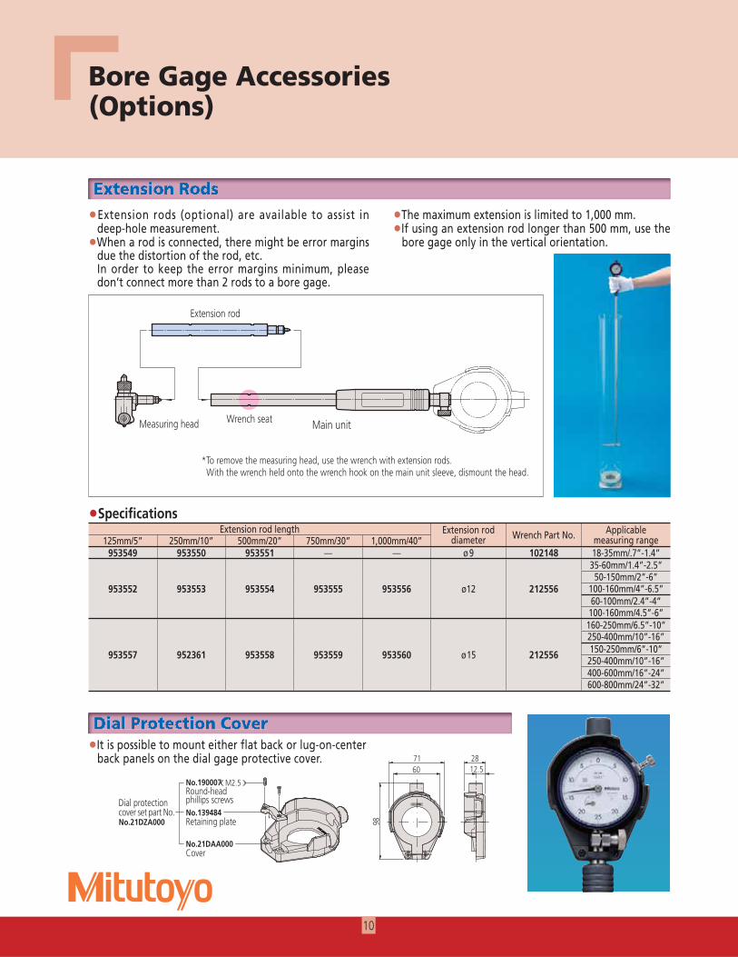
Extension rods (optional) are available to assist in deep-hole measurement.When a rod is connected, there might be error margins due the distortion of the rod, etc.
In order to keep the error margins minimum, please don’t connect more than 2 rods to a bore gage.
The maximum extension is limited to 1,000 mm.If using an extension rod longer than 500 mm, use the bore gage only in the vertical orientation.
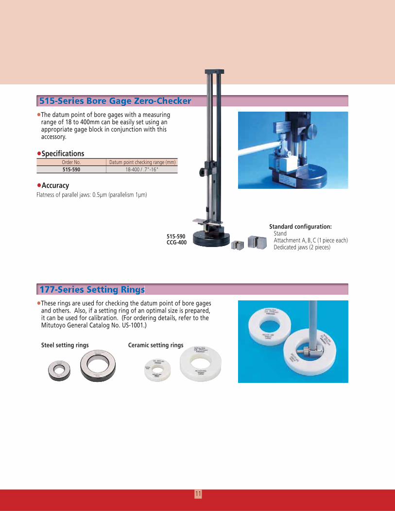
It is possible to mount either flat back or lug-on-center back panels on the dial gage protective cover.
12.52871
60
98
No.190007(M2.5)十字穴付きナベコねじ
No.139484押さえ板
No.21DAA000カバー
保護カバーセットパーツNo.No.21DZA000
継足ロッド
ヘッドスパナ掛かり
本体
SpecificationsExtension rod length Extension rod
diameter Wrench Part No. Applicable measuring range125mm/5” 250mm/10” 500mm/20” 750mm/30” 1,000mm/40”
953549 953550 953551 — — ø9 102148 18-35mm/.7”-1.4”35-60mm/1.4”-2.5”50-150mm/2”-6”
953552 953553 953554 953555 953556 ø12 212556 100-160mm/4”-6.5”60-100mm/2.4”-4”
100-160mm/4.5”-6”160-250mm/6.5”-10”250-400mm/10”-16”
953557 952361 953558 953559 953560 ø15 212556 150-250mm/6”-10”250-400mm/10”-16”400-600mm/16”-24”600-800mm/24”-32”
EExttensiiion RRodddsEExttensiiion RRoddds
DDiiialll PProttecttiiion CCoverDDiiialll PProttecttiiion CCover
10
Main unitWrench seat
Dial protection cover set part No.
ound-head phillips scre s
etaining plate
Cover
Extension rod
Measuring head
551155-SSeriiies BBore GGaggge ZZero-CChhheckkker 551155-SSeriiies BBore GGaggge ZZero-CChhheckkker
11 - eries e ing ings117777-SSeriiies SSettttiiinggg RRiiingggs117777-SSeriiies SSettttiiinggg RRiiingggs
SpecificationsOrder No. Datum point checking range (mm)515-590 18-400 / .7"-16"
The datum point of bore gages with a measuring range of 18 to 400mm can be easily set using an appropriate gage block in conjunction with this accessory.
These rings are used for checking the datum point of bore gages and others. Also, if a setting ring of an optimal size is prepared, it can be used for calibration. (For ordering details, refer to the Mitutoyo General Catalog No. US-1001.)
Standard configuration: Stand Attachment A, B, C (1 piece each)
Accuracy
Steel setting rings Ceramic setting rings
515-590CCG-400
11
Aurora, Illinois(Corporate Headquarters)
Westford, Massachusetts
Huntersville, North Carolina
Mason, Ohio
Plymouth, Michigan
City of Industry, California
One Number to Serve You Better1-888-MITUTOYO (1-888-648-8869)
Note: All information regarding our products, and in particular the illustrations, drawings, dimensional and performance data contained in this printed matter as well as other technical data are to be regarded as approximate average values. We therefore reserve the right to make changes to the corresponding designs. The stated standards, similar technical regulations, descriptions and illustrations of the products were valid at the time of printing. In addition, the latest applicable version of our General Trading Conditions will apply. Only quotations submitted by ourselves may be regarded as definitive.
Mitutoyo products are subject to US Export Administration Regulations (EAR). Re-export or relocation of Mitutoyo products may require prior approval by an appropriate governing authority.
Trademarks and RegistrationsDesignations used by companies to distinguish their products are often claimed as trademarks. In all instances where Mitutoyo America Corporation is aware of a claim, the product names appear in initial capital or all capital letters. The appropriate companies should be contacted for more complete trademark and registration information.
We reserve the right to change specifications and prices without notice.