Embed Size (px)
Citation preview

Inside US: +1 (877) 432-9908 Bulletin No. GMJ1939-D
Outside US: +1 (717) 767-6511 Drawing No. LP0960
www.redlion.net Released 2017-03-30
-1-
Model GMJ1939 ‐ Graphite® J1939 Module
C USULR
LISTEDIND.CONT. EQ.
3PWL
FOR USE IN HAZARDOUS LOCATIONS: Class I, Division 2, Groups A, B, C, and D T4
• CONFIGURED USING CRIMSON® SOFTWARE (VERSION 3.0 OR LATER)
• DIGITALLY ISOLATED J1939 PORT CAPABLE OF COMMUNICATING WITH ANY J1939 DEVICE
• POWERED AND CONFIGURED FROM GRAPHITE HOST DEVICE
• BUILT-IN TERMINATION RESISTOR SELECTABLE THROUGH A SWITCH
C US LISTEDULR
IND. CONT. EQ.34AD
II 3 G Ex nA IIC T4 Gc-40°C ≤ TAMB ≤ 75°CDEMKO 14 ATEX 1387XIECEx UL 15.0035X
GENERAL DESCRIPTION The model GMJ1939 is a J1939 communication module designed for
use with the Graphite products. The module provides the Graphite hostdevice a J1939 communications port. It is built with digital isolation toprotect the Graphite host device from the J1939 bus and vice versa. Itprovides the ability to communicate to any J1939 device. The GMJ1939module has a termination resistor built-in, and is selectable through aswitch. The connector is pluggable for easy removal of the GMJ1939module from the J1939 bus, without disturbing communications withother devices on the bus.
The modules connect and communicate via proprietary USBconnection to the various Graphite devices. The Graphite devices,equipped with serial ports as well as Ethernet port(s), allows the systemto share data with PCs, PLCs and SCADA systems. The maximumnumber of modules varies for each Graphite device, see specific modelfor details. Remove power from the host device before installing orreplacing any modules.
CONFIGURATIONThe Graphite is configured with Windows® compatible Crimson 3
software. The software is an easy to use, graphical interface whichprovides a means of configuration and commissioning of new systems,as well as routine module re-calibration.
SAFETY SUMMARYAll safety related regulations, local codes and instructions that appear
in this literature or on equipment must be observed to ensure personalsafety and to prevent damage to either the instrument or equipmentconnected to it. If equipment is used in a manner not specified by themanufacturer, the protection provided by the equipment may beimpaired.
Do not use this unit to directly command motors, valves, or otheractuators not equipped with safeguards. To do so can be potentiallyharmful to persons or equipment in the event of a fault to the unit.
ORDERING INFORMATION
A listing of the entire Graphite family of products and accessories can be found at www.redlion.net.
4.65(118)
2.80 (71) 1.25 (32)
DIMENSIONS In inches (mm)
DESCRIPTION PART NUMBER
Graphite Module, J1939 Interface GMJ19390
WARNING - EXPLOSION HAZARD - DO NOT DEQUIPMENT UNLESS POWER HAS BEEN SWOR AREA IS KNOWN TO BE NON-HAZARDOU
CAUTION: Risk of Danger.Read complete instructions prior to installation and operation of the unit.
WARNING - EXPLOSION HAZARD - DO NOT DISCONNECT EQUIPMENT UNLESS POWER HAS BEEN SWITCHED OFF OR AREA IS KNOWN TO BE NON-HAZARDOUS.
WARNING - EXPLOSION HAZARD - DO NOT DISCONNECT EQUIPMENT UNLESS POWER HAS BEEN SWITCHED OFF OR AREA IS KNOWN TO BE NON-HAZARDOUS.
WARNING - EXPLOSION HAZARD - SUBSTITUTION OF COMPONENTS MAY IMPAIR SUITABILITY FOR CLASS I, DIVISION 2.

-2-
Bulletin No. GMJ1939-D Released 2017-03-30
Drawing No. LP0960
SPECIFICATIONS1. POWER: Power will be supplied by the Graphite host device. Some
modules, depending on usage may consume high levels of power. Thismay limit the total number of modules that can be installed on a singleGraphite host. Check the Graphite module and Graphite host datasheets for specific usage and power requirements. GMJ1939 Max Power: 1.2 W
2. COMMUNICATIONS: J1939 Port: The J1939 port has format and baud rates that are
software programmable up to 250K baud and is digitally isolated.124 ohm, 1W termination is provided through a switch. This portmay be configured for various J1939 protocols.
Isolation from GMJ1939 Communication ports to Graphite host device:1000 VDC for 1 minute.
3. ENVIRONMENTAL CONDITIONS:Operating Temperature Range: -40 to 75 °C, or lowest range among
equipment used in your Graphite system. Consult the user manualor www.redlion.net/OpTemp for further details.
Storage Temperature Range: -40 to +85 °COperating and Storage Humidity: 85% max. relative humidity, non-
condensing.Altitude: Up to 2000 meters
4. CERTIFICATIONS AND COMPLIANCES:CE Approved
EN 61326-1 Immunity to Industrial LocationsIEC/EN 61010-1RoHS Compliant
ATEX Approved II 3 G Ex nA IIC T4 Gc
DEMKO 14 ATEX 1387XEN 60079-0, -15
IECEx ApprovedEx nA IIC T4 GcIECEx UL 15.0035X
IEC 60079-0, -15UL Listed: File #E302106UL Hazardous: File #E317425ABS Type Approval for Shipboard Applications
5. CONSTRUCTION: Case body is all metal construction.6. CONNECTIONS: Removable wire clamp screw terminal blocks
Wire Gage: 28-14 AWG (0.32 mm - 1.63 mm) terminal gage wireTorque: 1.95-2.21 inch-lbs (0.22-0.25 N-m)
7. MOUNTING: Screws to host8. WEIGHT: 6.9 oz (196 g)
PORT 3ETHERNET
D
ISOLATED
ISOLATED
ISOLATED
A
POWERSUPPLY
+
-VDC
GRAPHITE HOST GMJ1939
PORT 2
C
COMMUNICATIONS
B
PORT 1PROGRAMMING
POWERSUPPLY
E
ISOLATED
PORT
Block Diagram for GMJ1939
EMC INSTALLATION GUIDELINESAlthough Red Lion Controls products are designed with a high degree
of immunity to Electromagnetic Interference (EMI), proper installation andwiring methods must be followed to ensure compatibility in eachapplication. The type of the electrical noise, source or coupling methodinto a unit may be different for various installations. Cable length, routing,and shield termination are very important and can mean the differencebetween a successful or troublesome installation. Listed are some EMIguidelines for a successful installation in an industrial environment.1. A unit should be mounted in a metal enclosure, which is properly
connected to protective earth.2. Use shielded cables for all Signal and Control inputs. The shield
connection should be made as short as possible. The connection pointfor the shield depends somewhat upon the application. Listed beloware the recommended methods of connecting the shield, in order oftheir effectiveness.a. Connect the shield to earth ground (protective earth) at one end
where the unit is mounted.b. Connect the shield to earth ground at both ends of the cable, usually
when the noise source frequency is over 1 MHz.3. Never run Signal or Control cables in the same conduit or raceway with
AC power lines, conductors, feeding motors, solenoids, SCR controls,and heaters, etc. The cables should be run through metal conduit thatis properly grounded. This is especially useful in applications wherecable runs are long and portable two-way radios are used in closeproximity or if the installation is near a commercial radio transmitter.Also, Signal or Control cables within an enclosure should be routed asfar away as possible from contactors, control relays, transformers, andother noisy components.
4. Long cable runs are more susceptible to EMI pickup than short cable runs.5. In extremely high EMI environments, the use of external EMI
suppression devices such as Ferrite Suppression Cores for signal andcontrol cables is effective. The following EMI suppression devices (orequivalent) are recommended:
Fair-Rite part number 0443167251 (Red Lion Controls #FCOR0000)Line Filters for input power cables:
Schaffner # FN2010-1/07 (Red Lion Controls #LFIL0000)6. To protect relay contacts that control inductive loads and to minimize
radiated and conducted noise (EMI), some type of contact protectionnetwork is normally installed across the load, the contacts or both. Themost effective location is across the load.a. Using a snubber, which is a resistor-capacitor (RC) network or metal
oxide varistor (MOV) across an AC inductive load is very effective atreducing EMI and increasing relay contact life.
b. If a DC inductive load (such as a DC relay coil) is controlled by atransistor switch, care must be taken not to exceed the breakdownvoltage of the transistor when the load is switched. One of the mosteffective ways is to place a diode across the inductive load. MostRed Lion products with solid state outputs have internal zener diodeprotection. However external diode protection at the load is always agood design practice to limit EMI. Although the use of a snubber orvaristor could be used.Red Lion part numbers: Snubber: SNUB0000
Varistor: ILS11500 or ILS230007. Care should be taken when connecting input and output devices to the
instrument. When a separate input and output common is provided,they should not be mixed. Therefore a sensor common should NOT beconnected to an output common. This would cause EMI on thesensitive input common, which could affect the instrument’s operation.
Visit www.redlion.net/emi for more information on EMI guidelines,Safety and CE issues as they relate to Red Lion products.
-3-
Released 2017-03-30 Bulletin No. GMJ1939-D
Drawing No. LP0960
CONFIGURATIONProgramming is done via Crimson 3 software, a Windows® compatible
configuration interface. Please see the Crimson manual for moreinformation.
J1939 PORT PROTOCOLSThe GMJ1939 module has one J1939 port. This port may be
configured for various J1939 protocols.
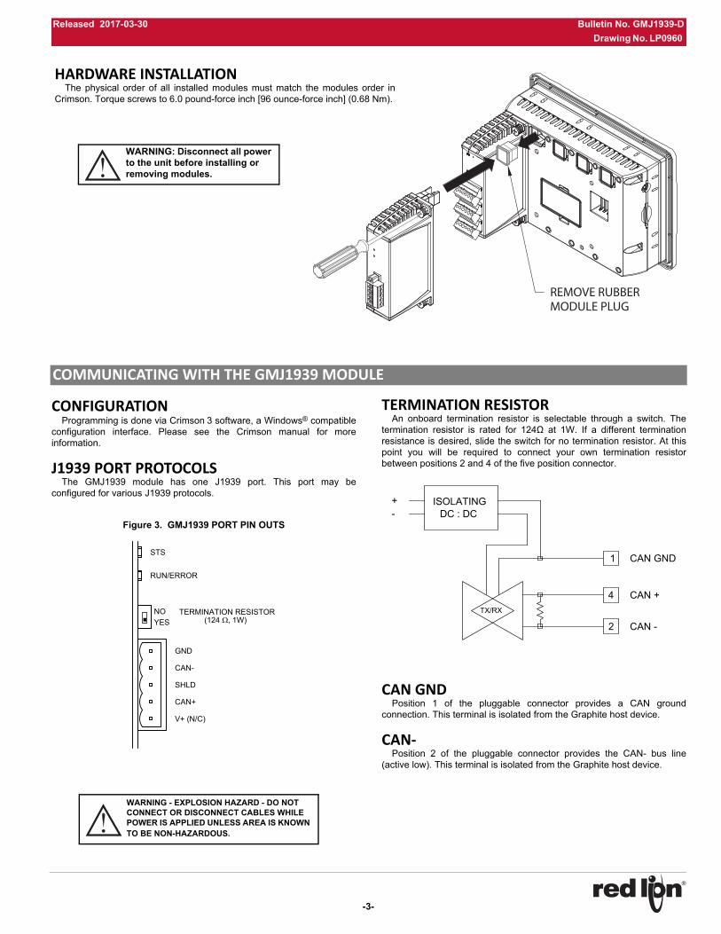
Figure 3. GMJ1939 PORT PIN OUTS
TERMINATION RESISTORAn onboard termination resistor is selectable through a switch. The
termination resistor is rated for 124Ω at 1W. If a different terminationresistance is desired, slide the switch for no termination resistor. At thispoint you will be required to connect your own termination resistorbetween positions 2 and 4 of the five position connector.
CAN GNDPosition 1 of the pluggable connector provides a CAN ground
connection. This terminal is isolated from the Graphite host device.
CAN‐Position 2 of the pluggable connector provides the CAN- bus line
(active low). This terminal is isolated from the Graphite host device.
RUN/ERROR
STS
(124 , 1W)TERMINATION RESISTOR
YESNO
SHLD
V+ (N/C)
GND
CAN-
CAN+
TX/RX
2
4
1 CAN GND
CAN +
CAN -
+-
ISOLATINGDC : DC
COMMUNICATING WITH THE GMJ1939 MODULE
REMOVE RUBBERMODULE PLUG
HARDWARE INSTALLATIONThe physical order of all installed modules must match the modules order in
Crimson. Torque screws to 6.0 pound-force inch [96 ounce-force inch] (0.68 Nm).
WARNING: Disconnect all power to the unit before installing or removing modules.
WARNING - EXPLOSION HAZARD - DO NOT CONNECT OR DISCONNECT CABLES WHILE POWER IS APPLIED UNLESS AREA IS KNOWN TO BE NON-HAZARDOUS.
-4-
Bulletin No. GMJ1939-D Released 2017-03-30
Drawing No. LP0960
SHLD (CAN SHIELD)Position 3 of the pluggable connector is provided for shield
connections. This position is available to tie shield wires to earth ground.The SHLD position is connected through a series RC network toCHASSIS as noted in specification J1939-11. The SHLD connection isinternally tied to the Graphite host device enclosure
CAN+Position 4 of the pluggable connector provides the CAN+ bus line
(active high). This terminal is isolated from the Graphite host device.
V+ (OPTIONAL 24 VDC)Position 5 of the pluggable connector is provided for optional 24 VDC
connections. This position is available only to tie 24 VDC wires together.The GMJ1939 module neither provides 24 VDC power nor uses 24 VDCpower through this connection. The V+ position is not connected to anycircuitry internal to the GMJ1939 module or Graphite Host device.
LEDs
STS – STATUS LEDThe Status LED is a green/red LED that provides information regarding
the state of the module. This includes indication of the various stages ofthe start-up routine (power-up), as well as any errors that may occur.
Startup Routine
Error States
RUN/ERROR LED
FIRMWARE UPGRADEThe module’s firmware is stored in flash memory so that software/
hardware conflicts are avoided, and so features can be added in thefuture.
During a download, Crimson compares its own library of firmware fileswith those stored in the module. If they do not match, Crimson willdownload the necessary firmware.
GRAPHITE TROUBLESHOOTINGIf for any reason you have trouble operating, connecting, or simply
have questions concerning your new Graphite unit, contact Red Lion’stechnical support.
Email: [email protected]: www.redlion.net
Inside US: +1 (877) 432-9908Outside US: +1 (717) 767-6511
Flashing RedModule is currently running the boot loader and/or being flash upgraded by Crimson.
Green Module performing normally.
Flashing Green Module has lost communication with the Host.
GreenGMJ1939 module established communication with other J1939 devices (RUN) and is communicating normally.
RedGMJ1939 module failed to establish communications with other J1939 devices (ERROR).
LIMITED WARRANTY(a) Red Lion Controls Inc. (the “Company”) warrants that all Products shall be free from defects in material and
workmanship under normal use for the period of time provided in “Statement of Warranty Periods” (available at www.redlion.net) current at the time of shipment of the Products (the “Warranty Period”). EXCEPT FOR THE ABOVE-STATED WARRANTY, COMPANY MAKES NO WARRANTY WHATSOEVER WITH RESPECT TO THE PRODUCTS, INCLUDING ANY (A) WARRANTY OF MERCHANTABILITY; (B) WARRANTY OF FITNESS FOR A PARTICULAR PURPOSE; OR (C) WARRANTY AGAINST INFRINGEMENT OF INTELLECTUAL PROPERTY RIGHTS OF A THIRD PARTY; WHETHER EXPRESS OR IMPLIED BY LAW, COURSE OF DEALING, COURSE OF PERFORMANCE, USAGE OF TRADE OR OTHERWISE. Customer shall be responsible for determining that a Product is suitable for Customer’s use and that such use complies with any applicable local, state or federal law.
(b) The Company shall not be liable for a breach of the warranty set forth in paragraph (a) if (i) the defect is a result of Customer’s failure to store, install, commission or maintain the Product according to specifications; (ii) Customer alters or repairs such Product without the prior written consent of Company.
(c) Subject to paragraph (b), with respect to any such Product during the Warranty Period, Company shall, in its sole discretion, either (i) repair or replace the Product; or (ii) credit or refund the price of Product provided that, if Company so requests, Customer shall, at Company’s expense, return such Product to Company.
(d) THE REMEDIES SET FORTH IN PARAGRAPH (c) SHALL BE THE CUSTOMER’S SOLE AND EXCLUSIVE REMEDY AND COMPANY’S ENTIRE LIABILITY FOR ANY BREACH OF THE LIMITED WARRANTY SET FORTH IN PARAGRAPH (a).