Embed Size (px)
Citation preview
NASA AVSCOMContractor Report 4083 Technical Report 87-C-11
SAutomated Inspection andPrecision Grinding ofSpiral Bevel Gears
Harold Frint
Sikorsky Aircraft Division
United Technologies Corporation
Stratford, Connecticut
Prepared for .. -ELECTEPropulsion Directorate AUG 2 11987USAARTA-AVSCOM andNASA Lewis Research Centerunder Contract NAS3-25465 A
National Aeronautics Thi" dumont h s boon appravod-and Space Administration joy pblic rc1LoI.o and sale; its
Scientific and Technical * dii,~butio is unlimitocL
Information Office
1987
SUMMARY
An advanced manufacturing technique for tile design and in-process inspection ofspiral bevel gears, utilizing a computer-controlled multi-axis coordinatemeasuring machine, has been developed at Sikorsky Aircraft in a four-phase MM&Tprogram sponsored by the U.S. Army AVSCOM Propulsion Laboratory, Cleveland,Ohio.
The technique uses the Zeiss Model UMM-500 universal measuring machine inconjunction with an advanced Gleason Works software package that permits rapidoptimization of spiral bevel gear tooth geometry during initial tooth formdevelopmcnt end more precise control of the tooth profile in producti.-u. Theprocess involves three-dimensional mapping of spiral bevel gear tceth overtheir entire working surfaces, using the UMM-500, and quantitative comparisonof surface coordinates with nominal master gear values at some 45 grid points.In addition, this technique features a means for rapidly calculating correctivegrinding machine settings for controlling the tooth profile within specifiedtolerance limits.
This new positive control method eliminates most of the subjective decisionmaking involved in the present inspection method, which compares contactpatterns obtained when the gear set is run under light load in a rolling testmachine. It produces a higher quality gear with significant reduction ininspection time.
-des
LopyINSPECT E
6 _ - -
PREFACE
This report presents the results of a four-phase program to develop an improvedinspection method for spiral bevel gears. Phase I covers the definition anddevelopment of a final inspection method utilizing a multi-axis coordinatemeasuring machine. Phase II involves the extension of the method to in-processinspection of spiral bevel gears. A pilot production program was conducted inPhase III and final documentation was performed in Phase IV.
The work outlined herein was performed under U.S. Army Aviation Systems CommandContract NAS3 25465 under the technical monitorship of Daniel Pauze, U.S. ArmyPropulsion Laboratory, Cleveland, Ohio.
This program was conducted by Sikorsky Aircraft, Division of United Techno-logies, under the technical direction of Alphonse Lemanski, Program Manager,and J. Mancini, Chief of Design and Development of Transmissions. Principalinvestigators were Harold Frint, Senior Design Analyst, and Warren Glasow,Senior Manufacturing Research Engineer.
Acknowledgement is made to Theodore Krenzer and James Knope of the GleasonWorks, Rochester, New York for their support and especially for the use of theGleason-developed software package.
iv
TABLE OF CONTENTS
Page
SUMMARY iii
PREFACE v
INTRUDUCTION 1
STATE OF THE ART OF SPIRAL BEVEL GEAR MANUFACTURE 3
DEVELOPMENT OF A FINAL INSPECTION METHOD 10Bevel Gear Selection 10Test Gear Specimens 13Universal Multi-Axis Coordinate Measuring Machine 13Master Gear Data 18The Final Inspection Measurement Process 21Determination of Nominal Values 21The Measurement Process 22Measurement Results 23Discussion of Results 36Correlation with Taped Patterns 36Comparison of Nominal Values 37
DEVELOPMENT OF AN IN-PRCCESS INSPECTION TECHNIQUE 42G-Age Corrective Process 42Sensitivity Study 42Fabrication of Test Gear Specimens 42The Measurement Process 44Results >f Corrective Regrinds 44Discussion of Results 49Establishment of Tolerance Limits 49
PILOT PRODUCTION AND TEST PROGRAM 51Fabrication of Pilot Production Test Gears 51Inspection Results Configuration 1 51Inspection Results Configuration 2 51Inspection Results Configuration 3 51H-60 Main Test Facility 55Acceptance Test Program 55Test Results 55Discussion of Results 57
ECONOMIC COST ANALYSIS 60Basis for Economic Analysis 60Income/Expense Statement 60Results 60
CONCLUSIONS 64
APPENDIX I PROCESS SPECIFICATION 65
INTRODUCTION
Proper and reliable service from a pair of spiral bevel gears can beobtained only when they are manufactured accurately and mounted into precision-machined gearbox housings that position and maintain the driving and drivengear members in a specified three-dimensional relationship throughout theiruseful life. Gears produced on existing gear generating and grinding equipmentwill run smoothly and carry the design load without distress if tooth spacingis maintailied, the teeth are machined concentric with the rotating axis, andthe tooth profile contour is controlled so that maximum tooth pair conjugacy isachieved when operating under full load conditions.
Since it is impractical to design and fabricate gear teeth and gear mountsthat are free from deflections when operating under load, most high-power gearsare designed with tooth profile modifications along the tooth face and in theprofile direction to compensate for load-induced deformations and to preventload concentration at the ends or tips of the teeth resulting in excessivewear, scoring, or even tooth breakage.
The elemental inspection of tooth profiles that is commonly performed onspur and helical gears is not practical for spiral bevel gears because theshape and size of a bevel gear tooth varies over its face width instead ofbeing constant as in the case of a spur gear. Spiral bevel gears arecurrently inspected on a specifically-designed Gleason test machine, shown inFigure 1, which provides a rotating test of the gear pair simulating no-loadoperation lmder actual gearbox mounting conditions. Tooth contact patternsunder these rotating conditions can be observed by painting the teeth with amarking compound and running the gears with their mating master control gearsfor a few seconds in the gear tester with a light brake load. Because of thecompound curvatures inherent in the spiral bevel gear tooth form and theprofile modifications designed into the tooth, these gears typically exhibit alocalized composite tooth contact which, ideally, should spread out under fullload, filling the working area of the tooth with some easing off at the endareas of contact. The size, shape, and position of this tooth bearing patternis a gross indication of the tooth topology both up and down the tooth profileand lengthwise along the tooth face.
The task of the design and profile development phase of spiral bevel gearmanufacture is to obtain a localized test machine pattern of a size, shape, andlocation that will produce the desired full load contact pattern when run inthe gearbox. The task of the gear production phase is the consistent duplica-tion of this tooth shape during a production run and from one production run toanother.
Figure 1. Gleason Test Machine
2
STATE OF THE ART OF SPIRAL BEVEL GEAR MANUFACTURE
This current method of manufacturing primary drive spiral bevel gearsrequires an experienced and qualified organization. It is often expressed thatthe development of a spiral bevel gear is more of an art than a science. Thisexpression is based on the requirement for skilled bevel gear machine operatorswho mus; use their background experience to evaluate the position, shape andcontour of the gear tooth contact pattern produced by the rolling test in thetest machine. 71te machine operator's judgment is relied upon to datermine whatgrinding machine setting or sombination of settings is best used to correct anundesirable feature in the test pattern.
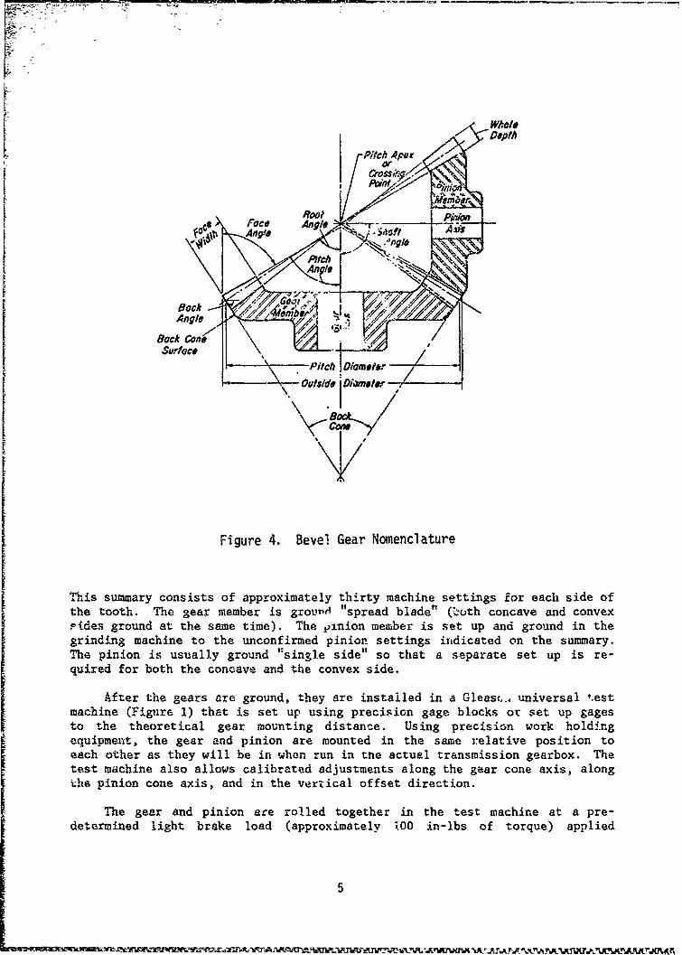
The Gleason gear 8rinding process is a culmination of motions and toolpaths that generate the bevel gear tooth form into a continually varyingnoninvolute curve. Basically, the Gleason gear grinder, shown In Figure 2, hasa cradle that supportý the formed grinding wheel shown and a radial oscillatingmotion while the wheel moves in and out of the gear tooth space. This cradlemotion is controlled by a generating cam that can be adjusted through thecradle angle setting to modify the ratio of motion at one end of the osci.llat-ing arc in relation to the other end. The gear to be ground is mounted on qwork holding fixture precisely centered to the work spindle that is in constantrotational motion In a controlled ratio to the cradle. The grinding wheel ismounted concentric to the cradle axis (see Figure 3) in a fixed relativeposition to the cradle center dependent upon the wheel radiun, the spiralangle, and hand of spiral. The grinding wheel, in effect, acts as a singletooth of an imaginary mating generating gear. The wheel is dressed automati-cally at prescribed stages in the grinding sequence to maint&in surface finishand profile accuracy. 'he geometry and nomenclature of a spiral bevel gear setis shown in Figure 4.
Gleason gear grinding machine setting changes involve first, second, andthird order changes. First order changes affect heel and toe position as wellas top and flank position. These changes are used in the final positioning ofthe tooth contact pattern. Second order changes include bias tdiagonal move-ment) changes, profile changes and wheel diameter changes. Third order changesinclude wheel dresser changes and heel and toe length changes. There areapproximately fourteen machine settings that are used by the machine operatoxin first order changes that affect the shape and position of the gear toothpattern. Second and third order charges require a calculation of values, usingformulas provided by the Gleason Works, by a gear engineer who is consultedprior to making second or third order changes.
When a new bevel gear set is to be produced in quantity, it is firstnecessary to "develop" the pair -- that is, to determ~ine the desired locationand shape of the tooth contact in the Gleason test machine that will provide asatisfactory full and uniform load contact pattern when run in the production,gearbox at the power and speed expected in service. This is currently accomp-lished by a trial and error process. The gear teeth are first semi-finish cutto size on a Gleason bevel gear generator (See Figure 5). The gear member ofthe pair is then set up in a Gleason bevel gear grinder (Figure 2) to the cal-culated but unconfirmed machine settings provided by a Gleason gear summary.
3
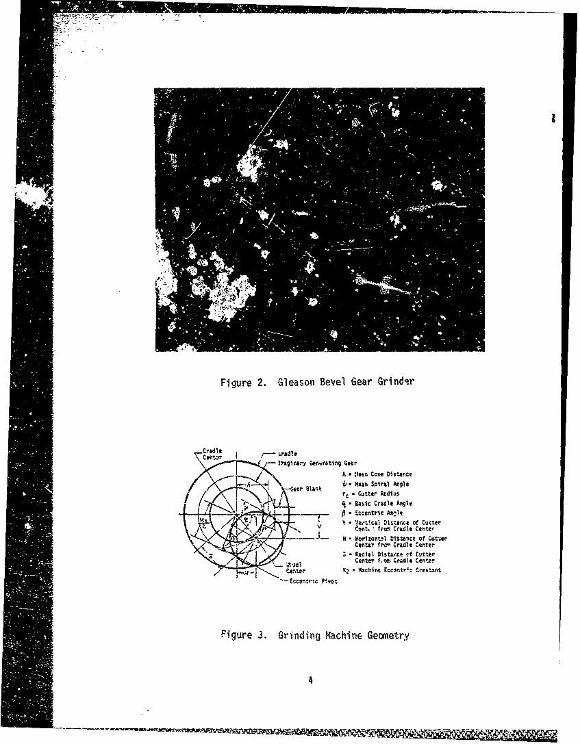
Figure 2. Gleason Bevel Gear Grind-r
Cradle
.nl;grnary Gentratin Gear
A - ;'ean Cone Distancemeor Blank - Mean Spiral Angle
n rlnk • Cutter RUdius
\ - B aaac Cradle Angle- 3 Eccentric An,•le
__L.V - VeYticai Distance of CutterV Cnt. * from Cradle Center
-...----- H . Horlzontl Distance of Cuti.erCenter ITN Cradle CentrPg Rdial DiStat~te 0f CutterCenter f1.s Cradlt CEntwr
- i Center K2 Mathntn Eccentric Crnstant
"`-Eccentric Pivot
Figure 3. Grinding Machine Geometry
4
\Pk A Pitc
r~ ---ro
Wtl
'a), Face IN /'-- PitchAngAn
II Bock
\0uthid_
Figure 4. Bevel Gear Nomenclature
This summary consists of approximately thirty machine settings for each side ofthe tooth. The gear member is ground "spread blade" (both concave and convexrides ground at the same time). The pinion member is set up and ground in thegrinding machine to the unconfirmed pinion settings iudicated on the summary.The pinion is usually ground '*single side" so that a separate set up is re-quired for both the concave and the convex side.
After the gears are ground, they are installed in a Gleasc,., universal t*estmachine (Figure 1) that is set up using precision gage blocks or set up gagesto the theoretical gear mounting distance. Using precision work holdingequipment, the gear and pinion are mounted in the same relative position toeach other as they will be in when run in the actual transmission gearbox. Thetest machine also allows calibrated adjustments along the gear cone axis, alongihe pinion cone axis, and in the vertical offset direction.
The gear and pinion are rolled together in the test machine at a pre-determined light brake load (approximately 00 in-lbs of torque) applied
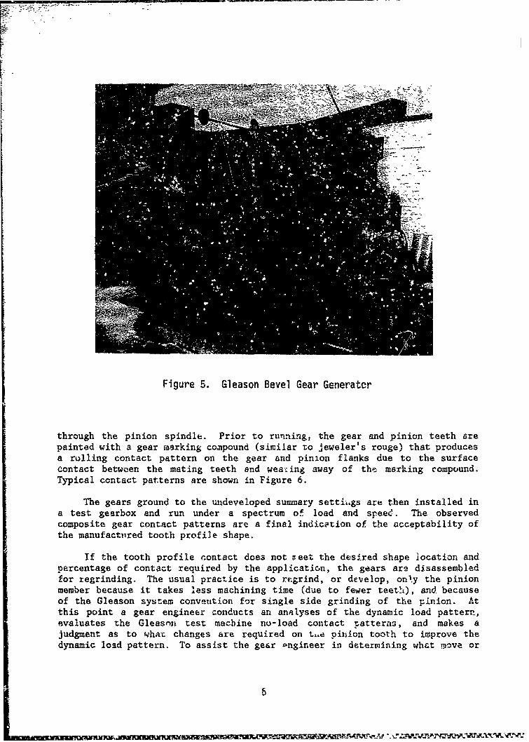
Figure 5. Gleason Bevel Gear Generater
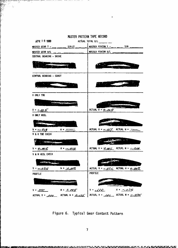
through the pinion spindle. Prior to running, the gear and pinion teeth arepainted with a gear foarking compound (similar to jeweler's rouge) that producesa rolling contact pattern on the gear and pinion flanks due to the surfacecontact between the mating teeth and wearing away of thc marking compound.Typical contact patterns are shown in Figure 6.
The gears ground to the undeveloped summary settii.gs are" then installed ina test gearbox and run under a spectrum of load and speee'. The observedcomposite gear contact patterns are a final indication of the acceptability ofthe manufactitred tooth profile shape.
If the tooth profile contact does not ,ueet the desired shape location andpercentage of contact required by the application, the gears are disassembledfor regrinding. The usual practice is to regrind, or develop, only the pinionmember because it takes less machining time (due to fewer teethi), and becauseof the Gleason system convetition for single side grinding of the pinion. Atthis point a gear engineer conducts an analyses of the dynamic load pattern,evaluates the Gleasnxt test macbine no-load contact patterns, and makes ajudgment as to what changes are required on t,.e pitn.ion tooth to improve thedynamic load pattern. To assist the gear Pngineer in determining what move or
MSTER PATTERN TAPE RECORD
APR 1 10 ACTUAL TOTAL B/A
MATR ERT _.,,____.S/Ni, -• MASTER PINION 1 -_ S/N_____
MASTER GFAR B/A - - MASTER PINION B/L
CEF.TRAL BEARING- DRIVE
V MNLY TOE
v -_•_• - ACTUAL V -
V ONLY HEEL
V - -, 0_ 1 H.. ACTUAL V -_ " ACTUAL H ------
V A V1 TOE CHECK
V =H ACTUAL V- ACTUAL H=
V & H HEEL CHECK
V , h a L - ACTUAL V -oz ACTUAL H - .- q "'
PROFILE PROFILE
V H .OOsA 4V V / I H' -- e2-S
ACTUAL V - • ACTUAL H = • ACTUAL V - _ .. __ ACTUAL H =-. .-
Figure 6. Typical Gear Contact Pattern
7
correction to the Gleason grinding machine set up is most appropriate, thepinion cone axis and the vertical offset 4n the test machine is adjusted tochange the pattern size and location. These adjustments provide an indicationto the gear engineer as to what grinding machine setting will be most effectivein changing the pattern, in most cases it takes a combination of two or moremoves to correct a pattern, and more than one combinaticn may produce similarresults, but always, one combination is more appropriate.
The pinion is reground to the new adjusted settings and the testing pro-cess repeated. The number of iterations r. essary to obtain a satisfactorygear profile depends upon the skill and experience of the test machine operatoror the gear engineers. This judgment process is probably the weakest link ingear tooth pattern development, even with experienced machine operators.
Once the development is complete, several sets of control gears are madethat duplicate the newly developed pair as precisely as possible. These mastercontrol gears are used to inspect the produi.tion gears. They are run in theGleason test machine against each mating gear sabsequently produced by thefinal machine settings to visually inspect the contact patterns against thoseobtained for the dev..oped master gear pair in order to assure Maintcnance ofuniform quality.
The production process control for spiral bevel gears is, in effect, aminiature development process except that the changes required to keep adrifting contact pattern situation under control are more subtle and involvethe visual comparison of a production gear pattern with the established mastergear pattern and the necessary corrective changes to keep the two in agreement.
The quality control process described above has certain inherent dis-advantages. :irst the acceptance or rejection of a production gear is basedupon a visual comparison of tooth contact patterns. Not only the size of thepattern, but its shape and location, are significant. Acceptance limits forthese features ave difficult to define quantitatively, therefore the accept/reject decision becomes a subjective one and is subject to the human frailtiesof the operator. Second, thn size, shape and location reluirements of thetooth contact pattern are peculiar to each gear mesh cnd ge6rbox mounting andno particular area, shape, or position can be considered universally ideal.Third, since the tooth contact is localized and tested under a very light load,it is necessary to determine not only that satisfactory contact patterns areobtained when the gears are mounted in their equivalent running position in thegear tester but to what extent this pattern is changed by axial and radialmovements of the pinion axis, with respect to the gear axis, that would movethe pattern to the limits of the tooth contact zone. This is known throughoutthe industry as the V and H check. By comparing patterns at these extreme Vand H settings, a cursory check on lengthwise and profile curvatures is main-tained. It should be noted that, in some cases, it is impossible to extend thecontact to the extreme corners of the tooth by this method.
It is apparent from the above discussion that there is a definite need fora more definitive and objective way of determining whether a bevel gear profileis acceptable and what specific changes are necessary in the grinding machinesettings to most efficiently bring an errant pattern situation under control
8
before it gets too far out of hand. It is important to control the toothprofile on highly loaded gears to within rather narrow limits. A 1 1oth profilewith excessive profile error will result in concentrations of load that couldcause scuffing, pitting, or even tooth breakage.
The automated inspection and precision grinding procedures developed inthis program, utilizing an automated multi-axis coordinate measuring machine,will satisfy this need for quantitative evaluation of a spiral bevel gear toothprofile in physical and measurable geometric terms without resorting to sub-jective visual comparisons of tooth contact patterns.
9
DEVELOPMENT OF A FINAL INSPECTION METHOD
Bevel Gear Selection
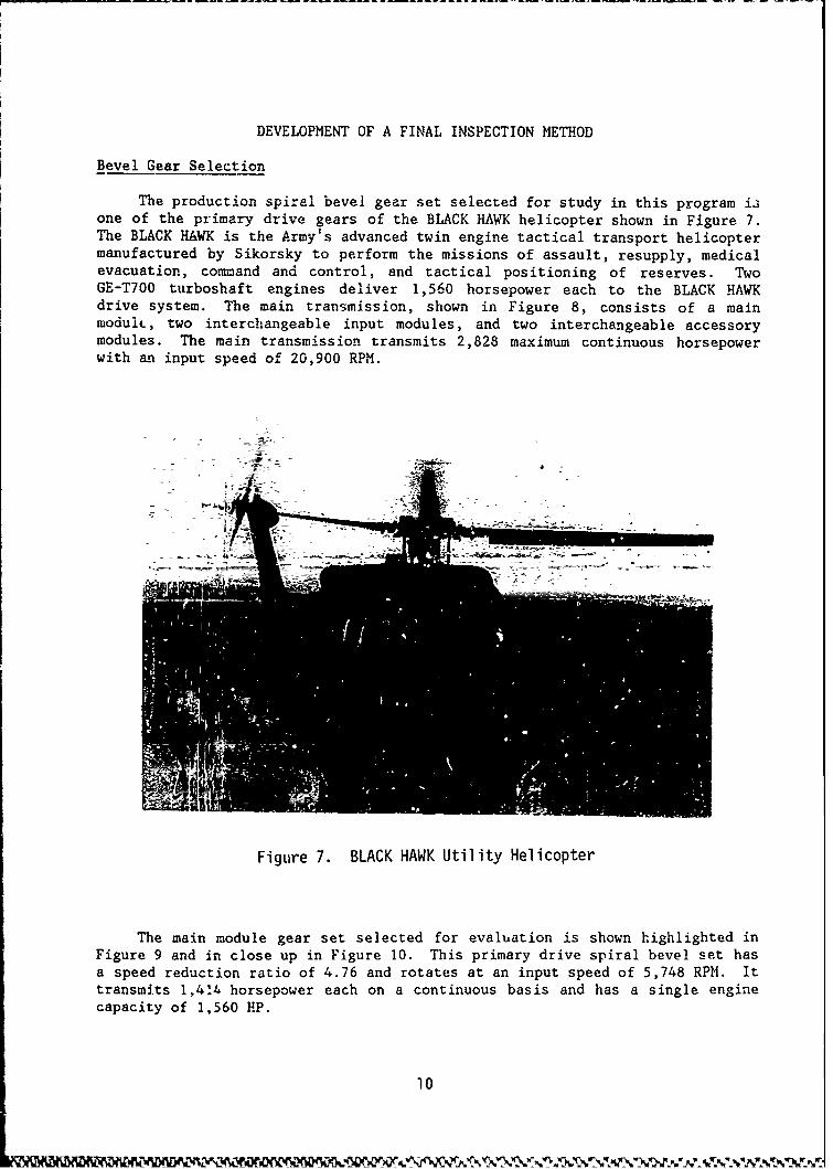
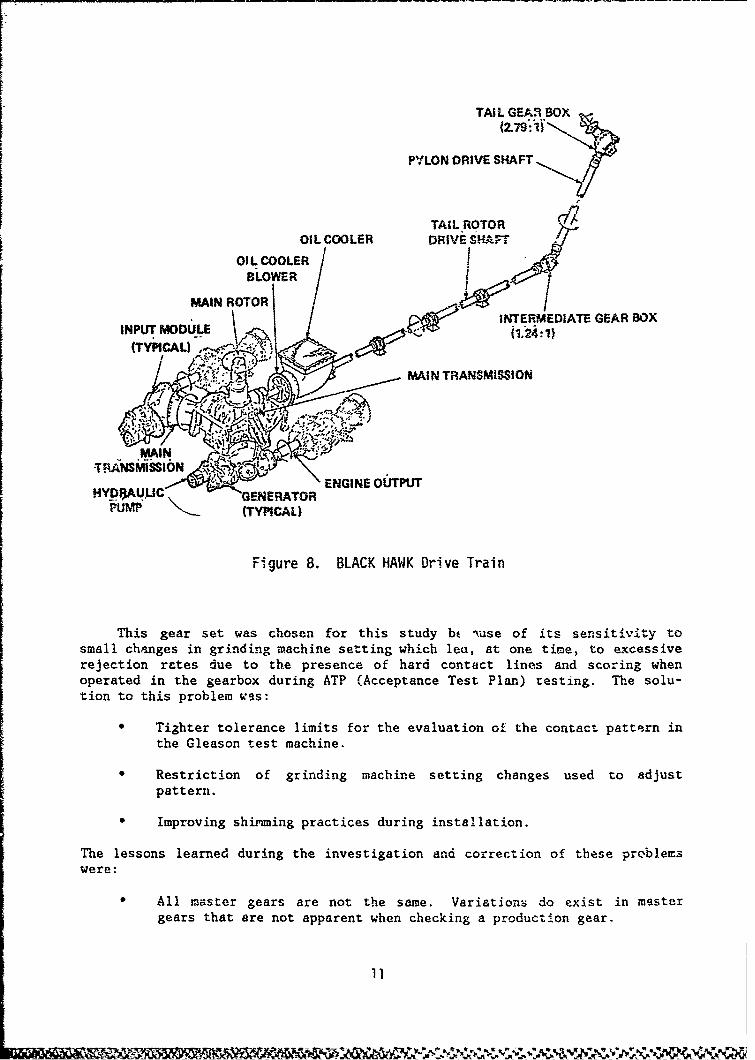
The production spiral bevel gear set selected for study in this program isone of the primary drive gears of the BLACK HAWK helicopter shown in Figure 7.The BLACK HAWK is the Army's advanced twin engine tactical transport helicoptermanufactured by Sikorsky to perform the missions of assault, resupply, medicalevacuation, command and control, and tactical positioning of reserves. TwoGE-T700 turboshaft engines deliver 1,560 horsepower each to the BLACK HAWKdrive system. The main transmission, shown in Figure 8, consists of a mainmoduiL, two interchangeable input modules, and two interchangeable accessorymodules. The main transmission transmits 2,828 maximum continuous horsepowerwith an input speed of 20,900 RPM.
Figure 7. BLACK HAWK Utility Helicopter
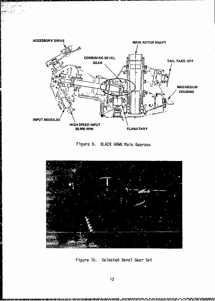
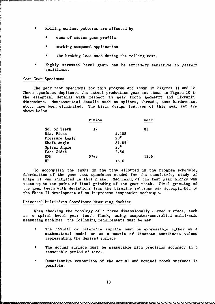
The main module gear set selected for evaluation is shown highlighted inFigure 9 and in close up in Figure 10. This primary drive spiral bevel set hasa speed reduction ratio of 4.76 and rotates at an input speed of 5,748 RPM. Ittransmits 1,4•4 horsepower each on a continuous basis and has a single enginecapacity of 1,560 HP.
10
TAIL GEAR .BOX(2.79:1)
PYLON DRIVE SHAFT
TAIL ROTOROIL COOLER DRIVE SP-A.FT
OIL COOLER /SLOWER /-
MAIN ROTORS/ INTERMEDIATE GEAR BOX
INPUT MODULE .A,1 -2,1)
: .- -MAIN TRANSMISION
MAINTRANSMISSION
HY U , \C EENGINE OUTPUTHVDIAU, , GENERATOR
PUMP (TYPICAL)
Figure 8. BLACK HAWK Drive Train
This gear set was chosen for this study bt Tuse of its sensitivity tosmall changes in grinding machine setting which lea, at one time, to excessiverejection rates due to the presence of hard contact lines and scoring whenoperated in the gearbox during ATP (Acceptance Test Plan) testing. The solu-tion to this problem was:
* Tighter tolerance limits for the evaluation of the contact pattern inthe Gleason test machine.
Restriction of grinding machine setting changes used to adjustpattern.
0 Improving shimming practices during installation.
The lessons learned during the investigation and correction of these problemswere:
All master gears are not the same. Variations do exist in mastergears that are not apparent when checking a production gear.
11
ACCESSORY DRIVE MAIN ROTOR SHAFT
• COMBINING BEVEL TAIL TAKE-OFF.. 50 - GEAR
~ HOUSING
INPUT MODULES
HIGH SPEED INPUT20,9W0 RPM PLANATARY
Figure 9. BLACK HAWK Main Gearbox
Figure 10. Selected Bevel Gear Set
12
* Rolling contact patterns are affected by
* wear of master gear profile.
* marking compound application.
* the braking load used during the rolling test.
* Highly stressed bevel gears can be extrcmely sensitive to patternvariations.
Test Gear Specimens
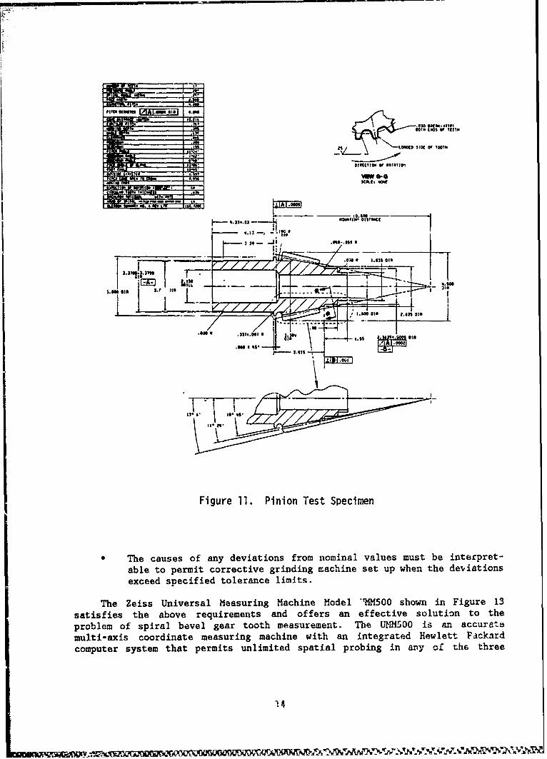
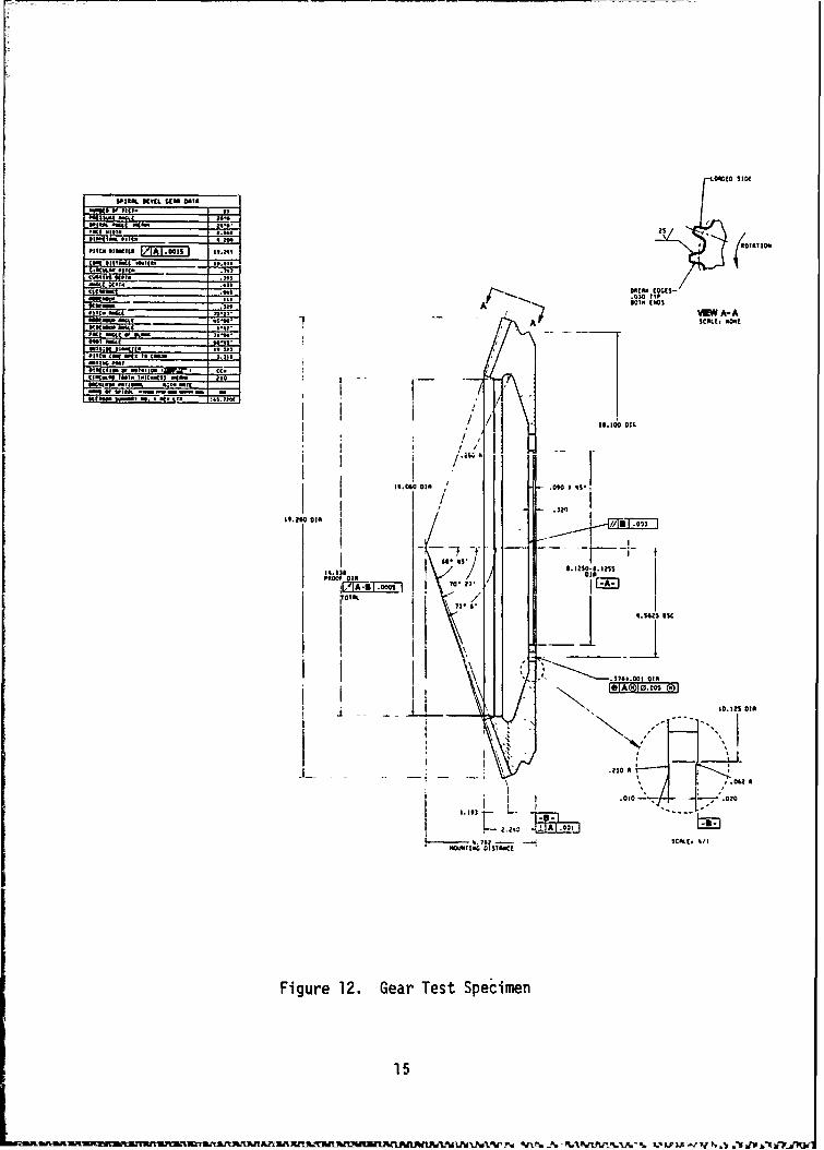
The gear test specimens for this program are shown in Fiagres 11 and 12.These specimens duplicate the actual production gear set shown in Figure 10 irthe essential details with respect to gear tooth geometry and fixturindimensions. Non-essential, details such as splines, threads, case hardnesses,etc., have been eliminated. The basic design features of this gear set areshown below.
Pinion Gear
No. of Teeth 17 81Dia. Pitch 4.108Pressure Angle 200Shaft Angle 81.850Spiral Angle 250Face Width 2.56RPM 5748 1206HP 1516
To accomplish the tasks in the time allotted in the program schedule,fabrication of the gear test specimens needed for the sensitivity study ofPhase II was initiated in this phase. Machining of the test gear blezilks wastaken up to the point of final grinding of the gear teeth. Final grinding ofthe gear teeth with deviations from the baseline settings was accomplished inthe Phase II development of an in-process inspection technique.
Universal Multi-Axis Coordinate Measuring Machine
When checking the topology of a three dimensionally % Lrved surface, suchas a spiral bevel gear tooth flank, using computer-controlled multi-axismeasuring machines, the following requirements must be met:
" The nominal or reference surface must be expressable either as amathematical model or as a matrix of discrete coordinate valuesrepresenting the desired surface.
"* The actual surface must be measurable with precision accuracy in areasonable period of time.
"* Quanticative comparison of the actual and nominal tooth surfaces ispossible.
13
OttoIIO
V 0TNI00
SCA~t, W0.
PT1..33..1 - -- -- f
.. 7 7 V 3* g
Figure01 2.63. Pipnietlpcie
The~41." cause ofaydvaiosfoIoialvle Aut eitrrt
multi-axi criatses measurdeinmachione with anomintegratued Hewletiterprckt-comptersysem tha permits unlecimegitedin spathia proin in whny the dhevithree
SPIhAL NVfi. StO 001*
aSI2S
no"I, M - A-
$3 W -"' II
WINAP AiSIS01 It 1.k 10-11 IS VL A-SIAokWmI -A IO
1: % 11 :11 Q 15- 8.4. cw ". Is - --
v5* "MI.CNV ISwr CC-fl
It"1 f". wts; I
-. 000M
48.t %S2
Figre12.13 Gea Test Specimen
15 0
~~~~~ ~~~~ A -MU 1A ~ 3 3 JS*f~ .lf R.AF.. ?(1 27, -A 11. <5P3 ,0 d ~ J .1I~
Figure 13. Zeiss UMM 500 Measuring Machine
orthogonal directions. This machine, in conjunction with a sophisticated 3Dsoftware package, provides a distinct and quantitative means of measuring andmapping three dimensional surface contours, In order to eccommodate thecomplex surface of the spiral bevel gear tooth, a precision indexing table,shown in Figure 14, was added as the 4th axis in gear measuring prcgrams. Thecomputer program packet for gear measurement permits the determination of theface profile coozdinates of spiral bevel teeth at an almost unlimited number ofprobe points on the tooth surface and a point by point comparison with storednominal reference values.
The UMM-500 was delivered with the model HP 9825 desk computer. Thesoftware pdckage purchased with the measuring machine included the UNESSprogram; which is a universal measuring program applied to the dimensionalmeasurement of planes, spheres, cylinders, and cones; and the RAM2 which is aspecial purpose spiral bevel gear measurement program with misalignmentcompensation on the rotary table.
Prior to the initiation of Phase II, it was discovered that the GleasonWorks was using a HP 9836 computer system with their Zeiss machine, and thesoftware that they had developed, and were supplying to Sikorsky, for use inPhase II was not compatible with the installed Sikorsky system. This discovery
16
FZ
Figure 14. Gear Member on Indexing Table
necessitated a retrofit of the liP 9825 computer system to convert it to the HPI9836 system. In this new system, the ')MET program replaces the UNESS program-T7he Gleason-developec*, program originally called the G-MET program pcerforms th~espiral bevel gear mep;ursments previously handled by the iRAM2 program, andadditionally r-ontains the corrective ieature twhIch calculates the necessarygrinding machine setting changes required to correct the profile.
The final automatic measuring and data processing system delvelope6.consists ofý several instrumnnts (Figure 13), which are controlled by a centra'jcomputer. The system al'iown includes Hewlett Packard 9836 Deskz- Top Computer,Zeiss UMMr500 Unive;:cl Measuring Macýhine, Hewlett Packard 9863-4 CassetteMemory, Hewlett Packard 9862A X-Y Plotter and Impact Line Printer. Duringmeasuremant, information is constantly being transferred between the centra).processor and the various peripherals (measuring machine and plotter) workingcontinuously. both of these devices are permitted only very afloit., process-dependent operating pauses, in parJicular a 1-second stabilizal-ion period forthe measuring machinse after contact. During the pause after probin-g, thecomputer prepares the information required for the next measuring point(coordinate traps formations, choice of contacting direction and detarm.inatiop.of t-he vrobe app roach path) and processes the measurement values (.-f theprevious point, initiating plotting and print-ine procedures.
17
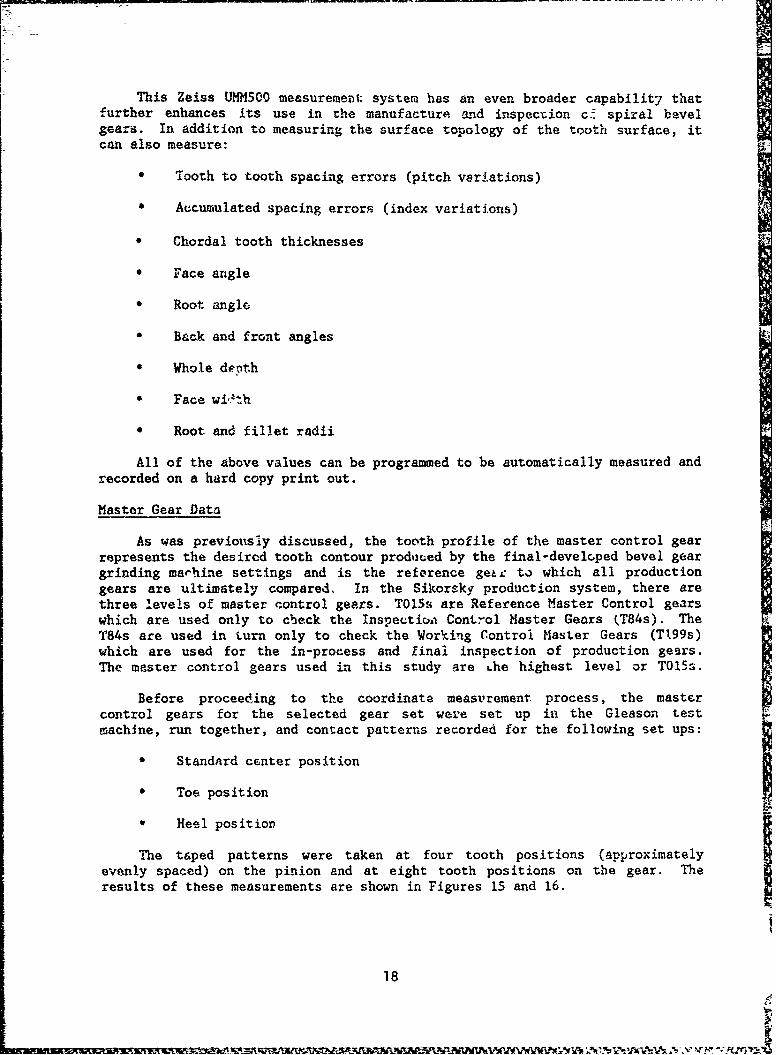
This Zeiss UMMSO0 measurement system has an even broader capabilit7 that
further enhances its use in the manufacture and inspection c spiral bevelgears. In addition to measuring the surface topology of the tooth surface, itcan also measure:
* Tooth to tooth spacing errors (pitch variations)
& Accumulated spacing errors (index variations)
* Chordal tooth thicknesses
0 Face angle
* Root angle
" Back and front angles
"* Whole depth
"* Face wi'th
"• Root and fillet radii
All of the above values can be programmed to be automatically measured andrecorded on a hard copy print out.
Master Gear Data
As was previously discussed, the tooth profile of the master control gearrepresents the desired tooth contour prodiuced by the final-develcped bevel geargrinding marhine settings and is the reference ge&L to which all productiongears are ultimately compared. In the Sikorsky production system, there arethree levels of master control gears. T015s are Reference Master Control gearswhich are used only to check the Inspection Control Master Gears (T84s). TheT84s are used in turn only to check the Working Control Master Gears (T199s)which are used for the in-process and final inspection of production gears.The master control gears used in this study are Lhe highest level or T0l5s.
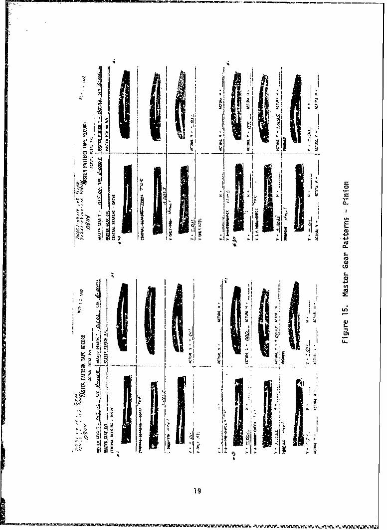
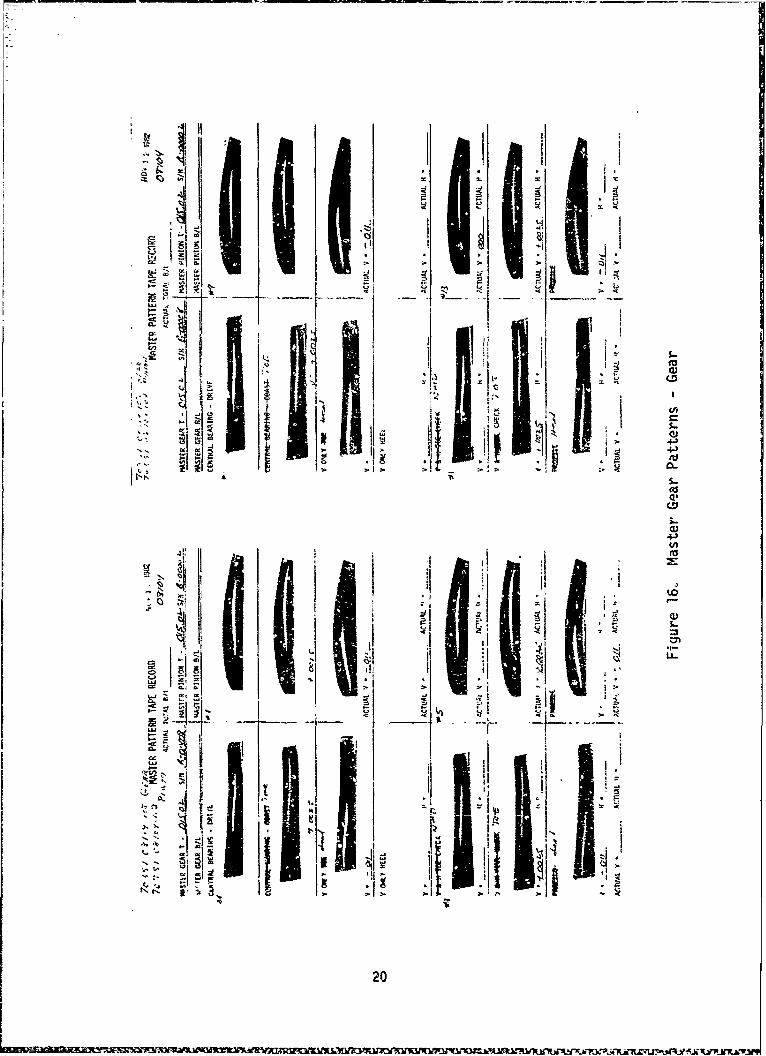
Before proceeding to the coordinate measurement process, the mastercontrol gears for the selected gear set were set up in the Gleason testmachine, run together, and contact patterns recorded for the following set ups:
* Standard center position
* Tor position
* Heel position
The taped patterns were taken at four tooth positions (approximatelyevenly spaced) on the pinion and at eight tooth positions on the gear. Theresults of these measurements are shown in Figures 15 and 16.
18
"I IleP ii i2- i
l = *
i I: , .. ~ *'•'
. I• • . .I
•.• •• • _5-
•t0N5
NEIII an
.4.J
-4417AýjK
- -, ~. ~* *4 2 0
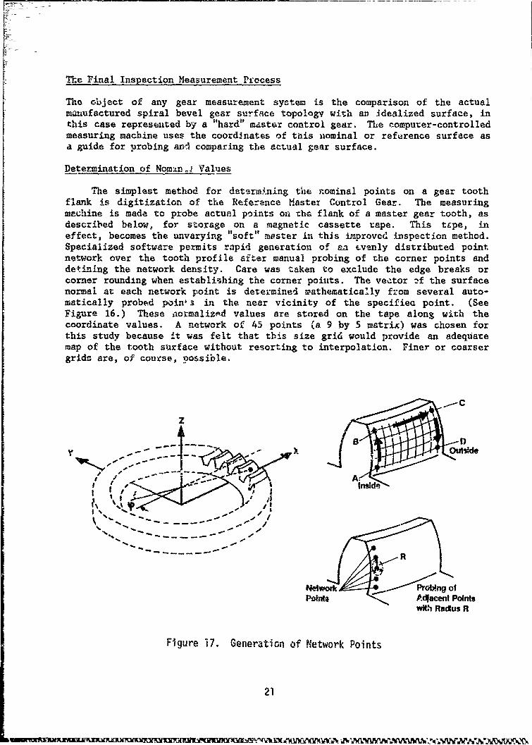
The Final Inspection Measurement ProcessThe object of any gear measurement system is the comparison of the actual
manufactured spiral bevel gear surface topology with an idealized surface, inthis case represented by a "hard" master control gear. The computer-controlledmeasuring machine uses the coordinates of this nominal or reference surface asa guide for probing anA comparing the actual gear surface.
Determination of Nomtn.J Values
The simplest method for detsrto.!ning tile nominal points on a gear toothflank is digitization of the Reference Master Control Gear. The measuringmachine is made to probe actual points on thG flank of a master gear tooth, asdescribed below, for storage on a magnetic cassette tape. This tcpe, ineffect, becomes the unvarying "soft" mwster in this improved inspection method.Specialized software permits rapid generation of an Evenly distributed pointnetwork over the tooth profile after manual probing of the corner points anddetining the network density. Care was taken to exclude the edge breaks orcorner rounding when establishing the corner points. The vector :-f the surfacenormal at each network point is determined mathematically from several auto-matically probed poinls in the near vicinity of the specifie point. (SeeFigure 16.) These iiormalizAd values are stored on the tape along with thecoordinate values. A network of 45 points (a 9 by 5 matrix) was chosen forthis study because it was felt that this size grid would provide an adequatemap of the tooth surface without resorting to interpolation. Finer or coarsergrids are, of course, possible.
zC
"----•
-Ail
S... "-.¾ =,
k__R
Network rW ofPOins Ac4acent Points
w#.lh Raclus R
Figure 17. Generation of Network Points
21
Even though spiral bevel gears possess a high degree of geometric com-plexity, it is feasible to expect that the nominal surface can be also gener-ated numerically by computer simulation of the manufacturing process. This, infact, was accomplished by the Gleason Works who provided assistance to SikorskyAircraft in this effort. Gleason provided the software, that converts finalgrinding machine settings, as reflected on a Gleason Grinding Summary, intoprofile coordinate points which are stored into the UMIM500 computer as nominalvalues. This method permits more freedom in the choice of the form and densityof the point network and provides a more theoretical baseline than the measuredmaster gear values, which themselves are subject to manufacturing errors. Anevaluation of both methods was made in this program by direct comparison of thenominal values, for a 45 point network, calculated by digitization of the T015master gear on the UMM500 and by mathematical simulation of the tooth surfaceaccomplished by the Gleason G-Age Program.
The Measurement Process
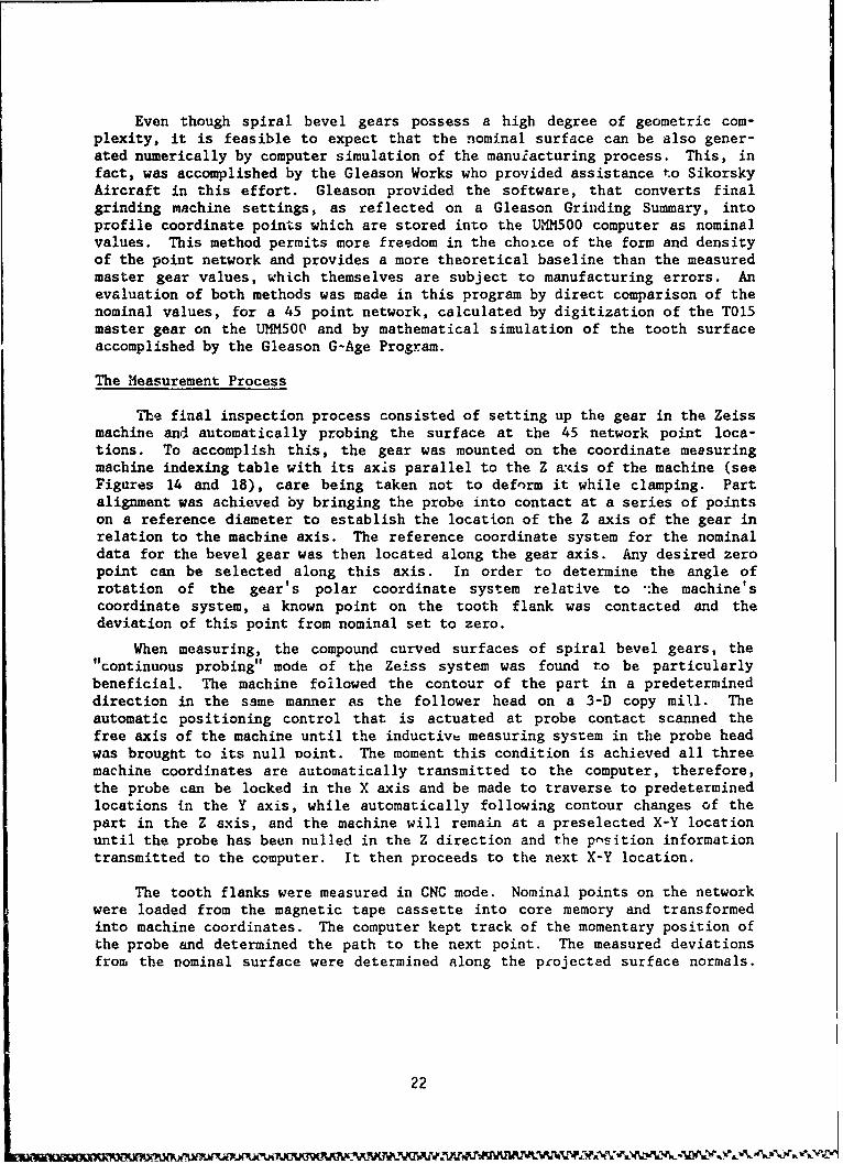
"The final inspection process consisted of setting up the gear in the Zeissmachine and automatically probing the surface at the 45 network point loca-tions. To accomplish this, the gear was mounted on the coordinate measuringmachine indexing table with its axis parallel to the Z axis of the machine (seeFigures 14 and 18), care being taken not to deform it while clamping. Partalignment was achieved by bringing the probe into contact at a series of pointson a reference diameter to establish the location of the Z axis of the gear inrelation to the machine axis. The reference coordinate system for the nominaldata for the bevel gear was then located along the gear axis. Any desired zeropoint can be selected along this axis. In order to determine the angle ofrotation of the gear's polar coordinate system relative to -:he machine'scoordinate system, a known point on the tooth flank was contacted and thedeviation of this point from nominal set to zero.
When measuring, the compound curved surfaces of spiral bevel gears, the"continuous probing" mode of the Zeiss system was found to be particularlybeneficial. The machine followed the contour of the part in a predetermineddirection in the same manner as the follower head on a 3-D copy mill. Theautomatic positioning control that is actuated at probe contact scanned thefree axis of the machine until the inductive measuring system in the probe headwas brought to its null Doint. The moment this condition is achieved all threemachine coordinates are automatically transmitted to the computer, therefore,the probe can be locked in the X axis and be made to traverse to predeterminedlocations in the Y axis, while automatically following contour changes of thepart in the Z axis, and the machine will remain at a preselected X-Y locationuntil the probe has been nulled in the Z direction and the p-sition informationtransmitted to the computer. It then proceeds to the next X-Y location.
The tooth flanks were measured in CNC mode. Nominal points on the networkwere loaded from the magnetic tape cassette into core memory and transformedinto machine coordinates. The computer kept track of the momentary position ofthe probe and determined the path to the next point. The measured deviationsfrom the nominal surface were determined along the projected surface normals.
22
evw
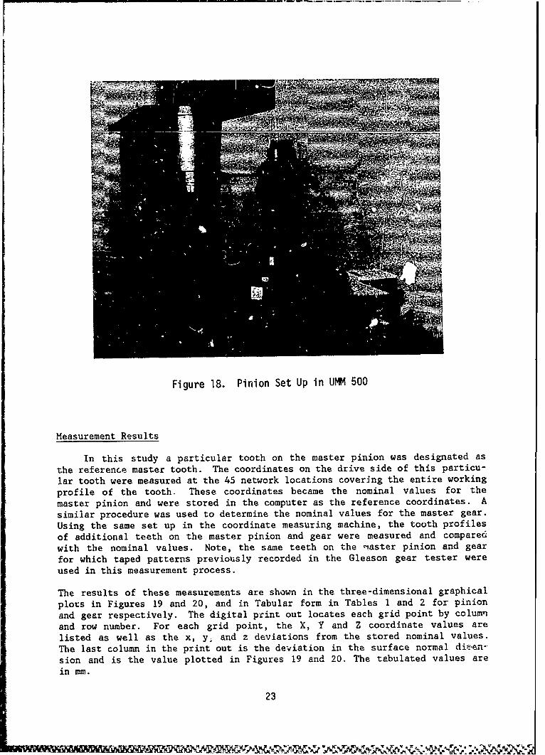
Figure 18. Pinion Set Up in UMM 500
Measurement Results
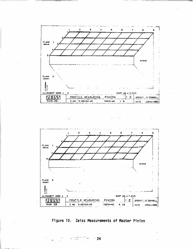
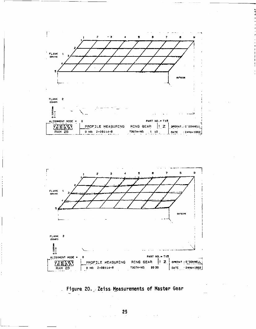
In this study a particular tooth on the master pinion was designated asthe reference master tooth. The coordinates on the drive side of this particu-lar tooth were measured at the 45 network locations covering the entire workingprofile of the tooth. These coordinates became the nominal values for themaster pinion and were stored in the computer as the reference coordinates. Asimilar procedure was used to determine the nominal values for the master gear.Using the same set up in the coordinate measuring machine, the tooth profilesof additional teeth on the master pinion and gear were measured and comparedwith the nominal values. Note, the same teeth on the -iaster pinion and gearfor which taped patterns previously recorded in the Gleason gear tester wereused in this measurement process.
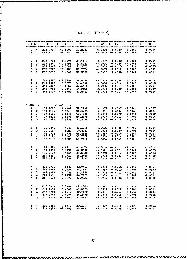
The results of these measurements are shown in the three-dimensional graphicalplots in Figures 19 and 20, and in Tabular form in Tables 1 and 2 for pinionand gear respectively. The digital print out locates each grid point by columnand row number. For each grid point, the X, Y and Z coordinate values arelisted as well as the x, y, and z deviations from the stored nominal values.The last column in the print out is the deviation in the surface normal di-,en-sion and is the value plotted in Figures 19 and 20. The tabulated values arein mm.
23
2 3 .. . .4 5 a 7 .. 9
2
FLANK 1 / 7(DRIVE) 3
OU.TSIDE
FLANK 2(COAST)
ALIGNýMET MODE - 0 __PART -NO.- T-015
PROFILE MEASU RING PINION0z PEnAT.: ODONNELLI
RAM-28 0 NO: ZOi4-5 TOOTH-NO: 15 DATE : 23Nov 1982
K2 3 4 a 8 7 8 a1
OUTSIDE~
FLANK 2(COAST)
ALIGNMENT MODE - 0 PRrL CSRN IINPART NO.- T-015
Nlý PRýTE M--'U...... INlN....[....zi .OPEAT;O'DO.NNE~L
RAM 26 0 NO: _Z-08104-45 TOOTH-NO: 9.13j DATE : 23ov 1992
Figure 19. Zeiss Measurements of Master Pinion
=24
. -3 4 8 6 7
FLANK I
(DAXVE)
FLANK 2(COAST)
ALIGNMENT MODE - 0 PART NO.- TI5
PaOF.ILE MEASURING RING GEAR Z ~ OPERAT.: OtDONNELL~RAM 20 D NO: Z-. 0 ... . TOOTH-NO: .. 10. D. _ 24NOV19.-2j
rl! 2 3 AE
OUT51DE
FLANK 2(COAST)
ALIGNMENT MODE - 0 PART NO.- TI1
IPROFILE MEASURING RING GEAR Z OPERAT.: ODONNELLý
RAM 2B , NO: Z-OB9,A-8 TOOTH-NO: 030 OATE :24NoY198a
Figure 20.. Ze-iss---Measurements of Master Gear
25
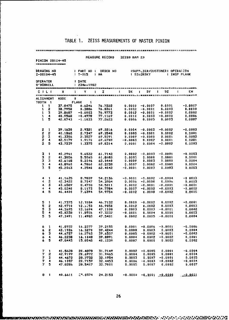
TABLE 1. ZEISS MEASUREMENTS OF MASTER PINION
MEASURE RECORD ZEISS RAM 23PINION 08104-45
DRAWING NO I PART NO I ORDER NO ISUPPLIER/CLISTOMERI OPERAI;ONZ-08104-45 I T-015 I NA I SIKORSKY I INSP FLANK
OPERATOR I DATEO'DONNELL I 23Nov1982
C I L I X I Y I Z I DX I DY I DZ I EN
ALIGNMENT MODE 0TOOTH I FLANK 1
1 1 37.8475 0.6246 76.7222 0.0000 -0.0007 0.0001 -0.00071 2 38.7958 0.3986 76.8361 0.0002 -0.0001 0.0003 0.00001 3 39.8687 -0.0003 76.9773 0.0012 -0.0001 -0.0002 0.00021 4 40.9568 -0.4978 77.1169 0.0010 0.0003 -0.0000 0.00061 5 42.0743 -1.1033 77.2623 0.0006 0.0005 0.0003 0.0007
2 1 39.1630 2.9321 69.2216 0.0004 -0.0003 -0.0002 -0.00032 2 40.1865 2.7347 69.3548 0.0005 -0.0001 0.0002 0.00012 Z 41.3306 2.3827 69.5091 0.0009 -0.0000 0.0001 0,00022 4 42.5179 1.9170 69.6708 -0.0003 0.0002 0.0001 0.00012 5 43.7239 1.3375 69.8314 0.0001 0.0004 -0.0002 0.0003
3 1 40.2961 5.6532 61.7142 0.0002 -0.0003 -0.0001 -0.00033 2 41.3856 5.5065 61.8683 0.0005 0.0000 0.0001 0.00013 3 42.6168 5.20?6 62.0440 0.0009 0.0003 0.0000 0.00043 4 43.8960 4.7860 62.2238 0.0007 0.0002 -0.0000 0.00043 5 45.2063 4.2540 62.4042 -0.0001 0.0003 0.0003 0.0003
4 1 41.1635 8.7839 54.2136 -0.0001 -0.0002 -0.0004 -0 00034 2 42.3422 8.7047 54.3884 0.0006 -0.0000 0.0006 0.00034 3 43.6589 8.4708 54.5811 0.0002 -0.0001 -0.0001 -0.00014 4 45.0240 8.1173 54.7784 0.0007 -0.0002 -0.0003 -0.00024 5 46.4400 7.6394 54.9754 -0.0002 0.0008 -0.0002 0.0005
5 1 41.7375 12.3184 46.7132 0.0000 -0.0002 0.0002 -0.00015 2 42.9710 12.,;50 46.9050 0.0012 0.0002 0.0003 0.00035 3 44.3695 12.1694 47.1180 0.0003 0.0003 -0.0001 0.00025 4 45.8338 11.8926 47.3332 -0.0001 0.0004 0.0000 0.00035 5 47.3491 11.4983 47.5481 0.0002 0.0005 -0.0000 0.0004
6 1 41.8922 16.2277 39.2155 0.0001 -0.0006 -0.0001 -0.00066 2 43.1926 16.3270 39.4244 0.0008 0.0003 0.0003 0.00046 3 44.6727 16.2762 39.6557 0.0005 -0.0002 -0.0001 -0.00036 4 46.2238 16.1048 39.8891 0.0004 0.0002 -0.0002 0.00016 5 47.8443 15.8048 40.1230 0.0007 0.0000 0.0002 0.0002
7 1 41.5628 20.4878 31.7149 0.0002 -0.0005 0.0001 -0.00047 2 42.9199 20.6972 31.9465 0.0004 0.0005 0.0001 d.00047 3 44.4672 20.7732 32.1954 0.0003 0.0007 -0.0001 0.00057 4 46.1097 20.7159 32.4453 0.0006 -0.0003 -0.0002 -0.00047 5 47.8286 20.5417 32.7001 0.0005 0.0007 0.0002 0.0007
8 1 40.6611 Z9.0574 24.2153 -0.0000 -01,0901 2 l .kw -0,O00i
26
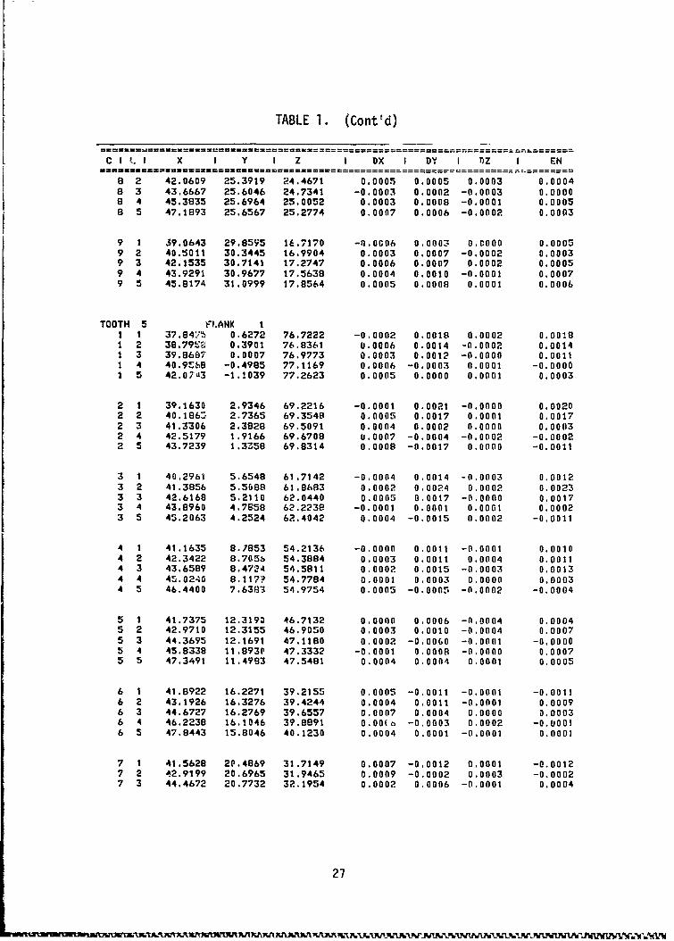
TABLE 1. (Cont'd)
I X I Y I Z I DX I DY I Z I EN0.0005 0.0005 0,0003 0.0004
8 3 43.6667 25:6046 24,7341 -0.0003 0.0002 -0.0003 0.00008 4 45.3835 25.6964 25.0052 0.0003 0.0008 -0.0001 0.0005
a 5 47.1893 25.6567 25.2774 0.0007 0.0006 -0.0002 0.0003
9 1 39.0643 29.8595 1&.7170 -0.0006 0.0003 0.0000 0.00059 2 40.5011 30.3445 16.9904 0.0003 0.0007 -0.0002 0.00039 3 42.1535 30.7141 17.2747 0.0006 0.0007 0.0002 0.00059 4 43.9291 30.9677 17.5638 0.0004 0.0010 -0.0001 0.00079 5 45.8174 31.0999 17.8564 0.0005 0.0008 0.0001 0.0006
TOOTH 5 FLANK I1 1 37.8475 0.6272 76.7222 -0.0002 0.0018 0.0002 0.00181 2 38.79L 0.3901 76.8361 0.0006 0.0014 -0.0002 0.00141 3 39.8697 0.0007 76.9773 0.0003 0.0012 -0.0000 0.00111 4 40.9S18 -0.4985 77.1169 0.0006 -0.0003 0.0001 -0.00001 5 42.07'13 -1.!039 77.2623 0.0005 0.0000 0.0001 0.0003
2 1 39.1630 2.9346 69.2216 -0.0001 0.0021 -0.0000 0.00202 2 40.186: 2.7365 69.3548 0.0005 0.0017 0.0001 0.00172 3 41.3306 2.3828 69.5091 0.0004 0.0002 0.0000 0.00032 4 42.5179 1.9166 69.6708 0.0007 -0.0004 -0.0002 -0.00022 5 43.7239 1.3358 69.8314 0.0008 -0.0017 0.0000 -0.0011
3 1 40.2961 5.6548 61.7142 -0.0004 0.0014 -0.0003 0.00123 2 41.3856 5.5088 61.8683 0.0002 0.0024 0.0002 0.00233 3 42.6168 5.2110 62.0440 0.0005 0.0017 -0.0000 0.00173 4 43.8960 4.7658 62.223e -0.0001 0.0001 0.0001 0.00023 5 45.2063 4.2524 62.4042 0.0004 -0.0015 0.0002 -0.0011
4 1 41.1635 8.7853 54.2136 -0.0000 0.0011 -0.0001 0.00104 2 42.3422 8.705b 54.3884 0.0003 0.0011 0.0004 0.00114 3 43.6589 8.4724 54.5811 0.0002 0.0015 -0.0003 0.00134 4 45.0240 8.117? 54.7784 0.0001 0.0003 0.0000 0.00034 5 46.4400 7.6383 54.9754 0.0005 -0.0005 -0.0002 -0.0004
5 1 41.7375 12.3190 46.7132 0.0000 0.0006 -0.0004 0.00045 2 42.9710 12.3155 46.9050 0.0003 0.0010 -0.0004 0.00075 3 44.3695 12.1691 47.1180 0.0002 -0.00 0 -0.0001 -0.00005 4 45.8338 11.893P 47.3332 -0.0001 0.000 -0.0000 0.00075 5 47.3491 11.4983 47.5481 0.0004 0.0004 0.0001 0.0005
6 1 41.8922 16.2271 39.2155 0.0005 -0.0011 -0.0001 -0.00116 2 43.1926 16.3276 39.4244 0.0004 0.0011 -0.0001 0.00096 3 44.6727 16.2769 39.6557 0.0007 0.0004 0.0000 0.00036 4 46.2238 16.1046 39.8891 0.00(b -0,0003 0.0002 -0.000!6 5 47.8443 15.8046 40.1230 0.0004 0.0001 -0.0001 0.0001
7 1 41.5628 2P.4869 31.7149 0.0007 -0,0012 0.0001 -0.00127 2 42.9199 20.6965 31.9465 0.0009 -0.0002 0.0003 -0.00027 3 44.4672 20.7732 32.1954 0.0002 0.0006 -0.0001 0.0004
27
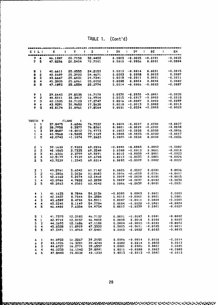
TABLE 1. (Cont'd)
CILI X I Y I Z I DX I DY I DZ I EN
7 4 46.1087 20.7158 32.4453 0.0003 -0.0005 -0.0001 -0.00057 5 47.8286 20.5404 72.7001 0.0010 -0.0006 0.0001 -0.0004
8 1 40.6611 25.0555 24.2153 0.0013 -0.0014 0.0001 -0.00158 2 42.0609 25.3923 24.4671 0.0003 0.0008 0.0003 0.00078 3 43.6667 25.6031 24.7341 0.0018 -0.0011 0.0001 -0.00118 4 45.3835 25.6961 25.0052 0.0008 0.0004 0.0000 0.00028 5 47.1893 25.6554 25.2774 0.0014 -0.0006 -0.0002 -0.0007
9 1 39.0643 29.8538 16.7170 0.0030 -0.0030 -0.0001 -0.00359 2 40.5011 30.3417 16.9904 0.0015 -0.0017 -0.0000 -0.00189 3 42.1535 30.7123 17.2747 0.0016 -0.0007 0.0000 -0.00099 4 43.9291 30.9652 17.5638 0.0018 -0.0013 0.0002 -0.00139 5 45.8174 31.0961 17.8564 0.0031 -0.0024 -0.0000 -0.0023
TOOTH 9 FLANK I1 1 37.8475 0.6246 76.7222 0.0000 -0.0007 0.0001 -0.00071 2 38.7958 0.3877 76.8361 0.0001 -0.0009 -0.0001 -0.00081 3 39.8687 -0.0012 76.9773 0.0003 -0.0008 0.0000 -0.00061 4 40.9568 -0.5005 77.1169 0.0008 -0.0023 -0.0002 -0.00171 5 42.0743 -1.1074 77.2623 0.0005 -0.0034 0.0000 -0.0026
2 1 39.1630 2.9323 69.2216 -0.0000 -0.0003 0.0002 -0.00022 2 40.1865 2.7335 69.3548 0.0008 -0.0013 0.0601 -0.00102 3 41.33C6 2.3799 69.5091 0.0010 -0.0028 -0.0001 -0.00232 4 42.5179 1.9139 69.6708 0.0013 -0.0037 0.0001 -0.00262 5 43.7239 1.3345 69.8314 0.0005 -0.0029 0.0002 -0.0022
3 1 40.2961 5.6542 61.7142 0.0005 0.0007 0.0001 0.00063 2 4i.3656 5.5656 6i.663 6.6t -u.Uuu u.uuuli -U.UUU/3 3 42.6168 5.2074 62.0440 0.0009 -0.0020 0.01101 -0.00153 4 43.8960 4.7822 62.2238 0.0009 -0.0037 0.0002 -0.00303 5 45.2063 4.2500 62.4042 0.0006 -0.0039 0.0001 -0.0031
4 1 41.1635 8.7846 54.2136 -0.0000 0.0003 0.0001 0.00034 2 42.3422 8.7044 54.3884 0.0010 -0.0001 0.0001 0.00014 3 43.6589 8.4700 54.5811 0.0007 -0.0011 0.0000 -0.000?4 4 45.0240 8.1149 54.7784 0.0004 -0.0028 -0.0001 -0.00244 5 46.4400 7.6354 54.9754 0.0015 -0.0039 0.0001 -0.002?
5 1 41.7375 12.3183 46.7132 0.0001 -0.0003 0.0001 -0.00025 L 42.9710 12.3157 46.9050 0.0008 0.0010 0.0000 0.00095 3 44.3695 12.1686 47.1180 0.0004 -0.0005 -0.0001 -0.00055 4 45.8338 11.8909 47.3332 0.0005 -0.0011 -0.0005 -0.00115 5 47.3491 11.4960 47.5481 0.0015 -0.0022 0.0002 -0.0015
6 1 41.8922 It.2267 39.2155 0.0006 -0.0014 0.0000 -0.00146 2 43.1926 16.3281 39.4244 0.0002 0.0014 0.0002 0.00136 3 44.6727 16.2771 39.6557 0.0001 0.000! 0.0001 0.00056 4 46.2238 16.1042 39.8891 0.0011 -0.0008 0.0003 -0.00056 5 47.8443 15.8030 40.1230 0.0013 -0.0013 -0.0005 -0.0013
28
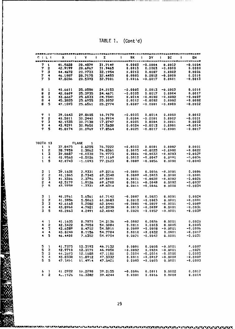
TABLE 1. (Cont'd)
CI!L I X I Y I Z I DX I DY I DZ I EN
7 1 41.5629 20.4879 31.7149 0.0003 -0.0004 0.00C2 -0,0004
7 2 42.9199 20.6967 31.9465 0.0013 0.0003 -0.0000 0.00007 3 44.4672 20.7733 32.1954 0.0013 0.0007 0.0002 0.00067 4 46.1087 20.7175 32.4453 0.0005 0.0012 -0.0000 0.00107 5 47.8286 20.5393 32.7001 0.0016 -0.0017 0.0001 -0.0013
8 1 40.6611 25.0588 24.2153 -0.0005 0.0013 -0.0003 0.00108 2 42.0609 25.3935 24.4671 -0.0005 0.0017 0.0004 0.00178 3 43.6667 25.6033 24.7341 0.0014 -0.0008 -0.0002 -0.00098 4 45.3835 25.6955 25.0052 0.0012 -0.0002 0.0002 -0.00028 5 47.1893 25.6561 25.2774 0.0007 -0.0001 -0.0000 -0.0002
9 1 39.0643 29.8605 16.7170 -0.0005 0.0014 0.0000 0.00129 2 40.5011 30.3440 16.9904 0.0004 -0.0001 0.0002 -0.00019 3 42.1535 30.7138 17.2747 0.0005 0.0004 0.0001 0.00029 4 43.9291 30.9650 17.5638 0.0024 -0.0013 0.0001 -0,00149 5 45.8174 31.0969 17.8564 0.0025 -0.0017 -0.0001 -0.0017
TOOTH 13 FLANK I1 1 37.8475 0.6255 76.7222 -0.0003 0.0001 0.0002 0.00011 2 38.7958 0.3862 76.8361 0.0005 -0.0025 -0.0000 -0.00221 3 39.8687 -0.0038 76.9773 0.0006 -0.0033 -0.0003 -0.00291 4 40.9569 -0.5026 77.116? 0.9012 -0.0047 0.0Afl1 -0.00*361 5 42.0743 -1.1093 77.2623 0.0009 -0.0056 0.0000 -0.0043
2 1 39.1630 2.9331 69.2216 -0.0001 0.0006 -0.0001 0.00062 2 40.1865 2.7345 69.3548 0.0009 -0.0003 0.0000 -0.00012 3 41.3306 2.3796 69.5091 0.0001 -0.0028 -0.0002 -0.00262 4 42.5179 1.9126 69.6708 0.0011 -0.0048 0.0002 -0.0037SS 4.7239 1.171 A9.R314 0.0011 -0.0046 0.0000 -0.0034
3 1 40.2961 5.6561 61.7142 -0.0007 0.0020 0.0001 0.00243 2 41.3856 5.5063 61.8683 0.0012 -0.0003 0.0001 -0.00013 3 42.6168 5.2082 62.0440 -0.0000 -0.0009 -0.0001 -0.00093 4 43.8960 4.7821 62.2238 0.0013 -0.0039 0.0001 -0.00313 5 45.2063 4.2491 62.4042 0.0020 -0.0052 -0.0001 -0.0039
4 1 41.1635 8.7870 34.2136 -0.0002 0.0026 0.0001 0.002t4 2 42.3422 8.7050 54.3884 0.0011 0.0003 0.0005 0.00054 3 43.6589 8.4702 54.5811 0.0009 -0.0008 -0.0001 -0.00064 4 45.0240 8.1156 54.7784 0.0010 -0.0022 0.0001 -0.00174 5 46.4400 7.6352 54.9754 0.0021 -0.0042 0.0001 -0.0031
5 1 41.7375 12.3193 46.7132 0.0001 0.0008 -0.0001 (1.00075 2 42.9710 12.3170 46.9050 -0.0002 0.0024 -0.0001 1.0021-5 3 ii.367s 12.i6GS 47.116; G.GG14 -C.GG45 4 45,8338 11.8912 47.3332 0.0011 -0.0012 -0.0000 -0.00095 5 47,3491 11.49*t4 47.5401 0.0002 -0.0005 0.0001 -0.0003
6 1 41.2922 16.2298 39.2i55 -0.0006 0.0011 0.0002 0.00126 2 4-.1926 16.3282 39.4244 0.0001 0.0016 0.0000 0.0014
ie
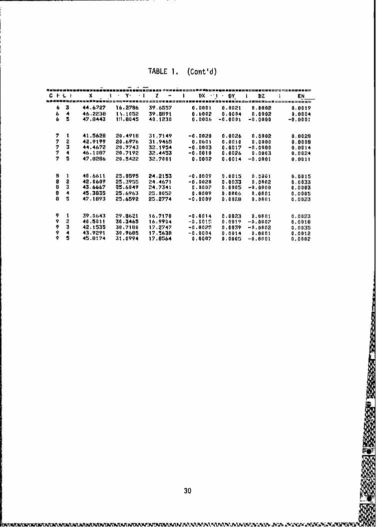
TABLE 1. (Cont'd)
X I Y- -1 Z - I DX i DY I DZ EN
6 3 44.6727 16.2786 39.6557 0.0001 0.0021 0.0002 0,00196 4 46.2238 IS.1052 39.8891 0.6002 0.0004 0.0002 0.00046 5 47.8443 1Vi.8045 40.1230 0.0006 -0.0001 -0.0000 -0.000!
7 1 41.5628 20.4918 31.7149 -0.0020 0.0026 0.0002 0.00297 2 42.9199 20.6976 31.9465 0.0601 0.0010 0.0000 0.00087 3 44.4672 20.7743 32.1954 -0.0003 0.0017 -0.0000 0.00147 4 46.1087 20.7192 32.4453 -0.0010 0.0026 0.0003 0.00247 5 47.8286 20.5422 32.7001 0.0002 0.0014 -0.0001 0.0011
8 1 40.6611 25.0595 24.2153 -0.0009 9.0015 0.0061 0.00158 2 42.0609 25.3955 24.4671 -0.0020 0.0033 0.0002 0.00338 3 43.6667 25.6049 24.7341 0.000? 0.0005 -0.0000 0.00038 4 45.3835 25.6963 25.0052 0.0009 0.0006 0.0001 0.00058 5 47.1893 25.6592 25.2774 -0.0009 O.O08 0.0001 0.0023
9 1 39.0643 29.8621 16.7170 -0.0014 0.0023 0.0001 0.00239 2 40.5011 30.3465 16.9904 -0.0015 0.0019 -0.000? O.OOt89 3 42.1535 30.7180 17.2747 -0.0025 0.0039 -0.0002 0.00359 4 43.9291 30.9685 17.5638 -0.0004 0.0014 0.0001 0.00129 5 45.8174 31.0994 17.8564 0.0007 0.0005 -0.0001 0.0002
30
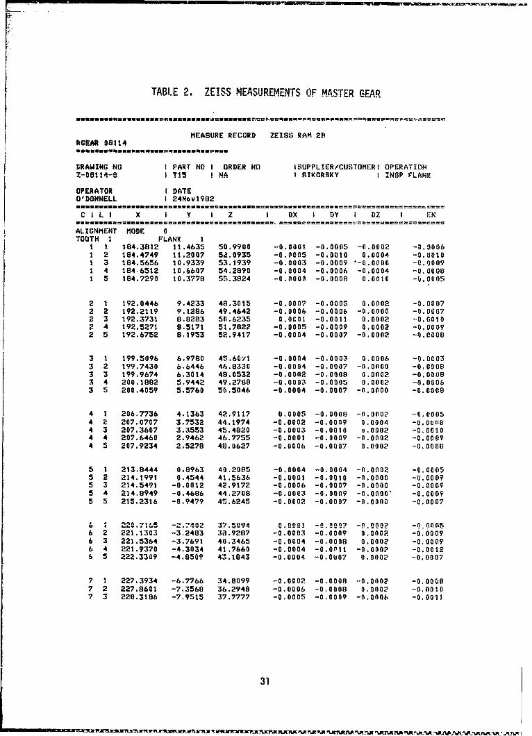
TABLE 2, ZEISS MEASUREMENTS OF MASTER GEAR
MEASURE RECORD ZEISS RAM 2BRGEAR 08114
DRAWING NO I PART NO I ORDER NO ISUPPLIER/CUSTOMERI OPERATIONZ-09114-8 I T15 I NA I SIKORSKY I INSP FLANK
OPERATOR I DATEO'DONNELL I 24Nov1982
C I L I X I Y I Z I DX I DY I DZ I EN
ALIGNMENT MODE 0TOOTH I FLANK I
1 1 184.3812 11.4635 50.9900 -.0.0001 -0.0005 -0.0002 -0.00061 2 184.4749 11.2007 52.0935 -0.0005 -0.0010 0.0004 -0.U0101 3 184.5656 10.9339 53.1939 -0.0003 -0.0009 "-0.0000 -0.00091 4 184.6512 10.6607 54.2890 -0.0004 -0.0006 -0.0004 -0.00081 5 184.7290 10.3778 55.3824 -0.0000 -0.0008 0.0010 -b.000!
2 1 192.0446 9.4233 48.3015 -0.0007 -0.0005 0.0002 -0.00072 2 192.2119 9.1286 49.4642 -0.0006 -0.0006 -0.0000 -0.00672 3 192.3731 8.8283 50.6235 0.0C01 -0.0011 0.0002 -0.00102 4 192.5271 8.5171 51.7822 -0.0005 -0.0009 0.0002 -0.00092 5 192.6752 8.1953 52.9417 -0.0004 -0.0007 -0.0002 -0.0008
3 1 199.5096 6.9780 45.6071 -0.0004 -0.0003 0.0006 -0.0C033 2 199.7430 6.6446 46.8330 -0.0004 -0.0007 -0.0000 -0.00083 3 199.9674 6.3014 48.0532 -0.0002 -0.0008 0.0002 -0.00083 4 200.1882 5.9442 49.2788 -0.0003 -0.0005 0.0002 -0.00063 5 200.4059 5.5760 50.5046 -0.0004 -0.0007 -0.0000 -0.0008
4 1 206.7736 4.1363 42.9117 0.0005 -0.0008 -0.0002 -0.00054 2 207.0707 3.7532 44.1974 -0.0002 -0.0009 0.0004 -0.001, 04 3 207.3607 3.3553 45.4820 -0.0003 -0.0010 u.0002 -0.00104 4 207.6460 2.9462 46.7755 -0.0001 -0.0009 -0.0002 -0.00094 5 207.9234 2.5278 48.0627 -0.0006 -0.0007 0.0002 -0.0008
5 1 213.8444 0.8963 40.2085 -0.0004 -0.0004 -0.0002 -0.00055 2 214.1991 0.4544 41.5636 -0.0001 -0.0010 -0.0000 -0.00095 3 214.5491 -0.0012 42.9172 -0.0006 -0.0007 -0.0000 -0.00095 4 214.8949 -0.4686 44.2708 -0.0003 -0.0009 -0.0000" -0.00095 5 215.2316 -0.9479 45.6245 -0.0002 -0.0007 -0.0000 -0.0007
6 1 220.7165 -2.?402 37.509i 20.00i -0.090? -9.0002 -0.Onfs6 2 221.1303 -3.2483 3R.9287 -0.0003 -0.0009 0.0002 -0.00096 3 221.5364 -3.7691 40.3465 -0.0004 -0.0008 0.0002 -0.00096 4 221.9370 -4.3034 41.7660 -0.0004 -0.0Pll -0.000? -0.00126 5 222.3309 -4.8509 43.1843 -0.0004 -0.0007 0.0002 -0.0007
7 1 227.3934 -6.7766 34.8099 -0.0002 -0.0008 --0.0002 -0.00087 2 227.8601 -7.3568 36.2948 -0.0006 -0.0008 0.0002 -0.00i07 3 228.3186 -7.9515 37.7777 -0.0005 -0.0009 -0.0006 -0.0011
31
~ 'Ln~f.~ R ~U~1~ !~ fl ~N'Z fU fU f.A fU ~fl~fl I
TAM)E 2. (Cont'd)
C I L i X I Y I Z I DY I DY I DZ I EN
7 4 228.7769 -8.5609 39,2638 -0.0005 -0.0009 -0.0002 -0.00107 5 229.2151 -9.:825 40.7471 -0.00(0o -0.0009 -0.0000 -0.0007
8 I 233,700 -I1.217t 32,1118 -0.0007 -0.0008 C.0004 -0.00108 2 234.3847 -1:.8789 33,6591 -0.0007 -0.0009 -0.0002 -0.00108 3 234.e925 -!;.5569 35,205!' 0,0006 -0.0013 0.0016 -0.00058 4 235.3917 -l3,•489 36.7574 -0.00G3 -0.0010 0,0002 -(.00098 5 235.8865 -I,.9562 3e.3093 -0.00G7 -O.uOd -0.0000 -0.0011
9 1 240.1425 -16.0746 29.4066 -0.0902 -0.0009 0.0002 -0.00089 2 240.7007 -16.8278 11.0240 -3.0008 -0.0010 0,0002 -0.00139 3 241.2507 -17.5953 32.6416 -0.0005 -0.0314 -0.0002 -0.00149 4 241.7960 -1C,3010 34.2556 -C.0004 -0.0008 0.0000 -0.00099 5 242.3357 -1?.1781 35.87%: -C.0004 -0.0011 -0.000? -0.0010
TOOTH 10 FLANK I1 1 184.381Z 11.464? 50.9990 0.0003 0.0007 -0.000! 0.00071 2 184.4749 il.20. 52.0935 0.0001 0.0004 -0.0001 0.00041 3 184.5656 10.934C b3.1939 -0.0004 -0.00P8 0.0010 -0.03071 4 184.6512 10.6600 54.2890 -0.0007 -0.00i3 -0.0002 -0.00151 5 184.7290 10.3776 55.33•4 -0.0003 -0.0010 0.0010 -0.0008
2 1 192.0446 9.4242 48.3015 l. 0 0 0 5 -0.0000 -0.0002 0.00012 2 192.2119 9.1283 49.4642 -0.0904 -0.P009 -0.0004 -0.0loO2 3 192.3731 8.71i? 50.6235 -0.0010 -0.0019 .. 00 1 -0.00212 4 192.5271 8.5166 51.7822 -0.0004 -0.0014 P.0001 -0.00142 5 192.6732 B.1952 52 9417 -0.006 -0.3008 0.0001 -0.01P09
3 t 199.5096 6.9770 45.6071 -0,0006 -0G.011 -0.0001 -0.10123 2 199.7439 6.6430 46.8330 -0.0011 -0.0021 0.0002 -0.00233 3 199.9674 6.3009 48.0532 -0.0005 -0.001; -0.0002 -0.00133 4 200.1892 5.9439 49.2780 -0.0004 -0 0007 -0.0002 -o.onoB3 5 :00.4059 5.5756 55.504,S -0.C204 -0,0011 (1.0000 -0.0111
4 1 206,7736 4.1342 42.91!7 -0.0003 -0.0025 0.0001 -0,01,)244 2 207.0707 -. 7524 44,1974 -0.0010 -0,0012 0.0001 -0,00154 3 207,3607 3.3550 45,4820 -0,1004 -0.0012 -0.0001 -0.00134 4 207.6460 2.9459 46.775! -0.91004 -0.0011 0.0002 -0.00114 5 207.9234 2,5277 46,0i,27 -0.1006 -O.0000 -0.0002 -0.0010
5 1 213.8444 O.994A .(1.2085 -0.0612 •-0.0019 0.0000 -0.00•25 2 •,4991 0.4541 41.5636 -0.0000 -C.0012 -0.0001 -0.00115 3 214.5491 -0.0017 42.,9172 -0 9006 -0.001i 0.0001 -0,00145 4 214.894? -0.4i94 44.2709 -0.0005 -0.0015 -0.0001 -0.00155 5 215.2316 -0.v482 4n,.245 -0.1004 -0.000B -0.0002 -0,0009
6 1 220.7165 -2.7412 37.ý094 -0.0907 -0.0017 0.000? -0,00136 2 221.1303 -3.2405 39.9287 -0.0008 -0.0008 0.0003 -0.OOl

TABLE 2. (Cont'd)
CILI X I D I DZ I EN[ -- - - - - -- - - - -
6 3 221.5364 -3.7697 40.3465 -0.0008 -0.001? -0.0001 -0.00146 4 221.9370 -4.30.i 41.7660 -0.0003 -0.0009 -0.0001 -0.00096 5 222.3309 -4.8513 43.1843 -0.0004 -0.0010 -0.0000 -0.0010
7 1 227.3934 -6.7776 34.8099 -0.0012 -0.001? 0.0002 -0.00167 2 227.8601 -7.3577 36.29A8 -0.0008 -0.0015 -0.0001 -0.00177 3 228.3186 -7.9516 37.7777 -0.0004 -0.0011 0.0001 -0.00117 4 228.7709 -8.5615 39.2638 -0.0008 -0.0013 0.0002 -0.00157 5 22V.2151 -9,1851 40.7471 -0.0011 -0.0026 0.0000 -0.0027
8 1 233.6700 -11.2190 32.1118 -0.0011 -0.0019 0.0000 -0.00218 2 z34.3847 -11.796 33.6581 -0.0011 -0.0011 -0.0001 -0.00168 1 234.8925 -12.5572 35.2059 0.0001 -0.0014 0.0020 -0.00078 4 235.3917 -13.2510 36.7574 -0.0010 -0.00P5 -0.0004 -0.00268 5 235.896S -13.9581 38.3099 -0.0014 -0.002Z 0.0001 -0.002b
9 1 240.1425 -11.0753 29.4080 -0.0006 -0.001.:- 0.0001 -0.0013
9 2 240.7007 -16.8280 31.0240 -0.0007 -0.0013 0.0002 -0.00149 3 241.2507 -17.5986 32.6416 -0.0017 -0.0036 0.0000 -0.00389 4 241.7960 -18.3831 34.2556 -0.0008 -0.0028 0.0013 -0.00249 5 242,3359 -19.1790 35.8751 -0.0009 -0.0016 0.0005 -0.0017
TOOTH 20 FLANK I1 1 184.3812 11.4663 50.9900 0.0014 0.0017 -0.0003 0.00201 2 184.4749 11.2015 52.0935 -0.0000 -0.0004 0.0003 -0.0003
1 3 184.5656 10.9328 53.1939 -0.0011 -0.0018 -0.0000 -0.00201 4 184.6512 10.6579 54.2890 -0.0019 -0.0031 0.0002 -0.00341 5 184.7290 10.3761 55.3824 -0.0010 -0.0019 -0.0002 -0.0A
2 1 192.0446 9.4234 48.3015 -0.0007 -0.0005 -0.0000 -0.00162 2 192,2119 9,1272 49.4642 -0.0008 -0.0019 0.0000 -0.00202 3 192.3731 8.8249 50.6235 -0.0017 -0.0038 -0.0001 -0.0041V.' 4 1ý'2.5271 8.5152 51.7822 -0.0014 -0,0023 -0.0003 -0.00272 5 192.6752 8.1951 52.9417 -0.0002 -0.0010 0.0004 -0.0010
3 1 199.5096 6.9759 45.6071 -0,0011 -0.0021 0.0003 -0.00233 2 199,7430 6.6403 46.8330 -0.0019 -0.0643 -6.0003 -0.00473 3 199.9674 6.2988 48.0532 -0.0018 -0.0027 -0.0000 -0.0C323 4 20a.1882 5.9440 49.2788 -0.0001 -0.0008 O.OOGO -0.00083 5 200.4159 5.5766 50.5046 -0.0002 -0.0002 0.0001 -0.0003
4 1 206.7736 4.1316 42.9117 -0.0015 -C.0044 -0.0004 -0.00464 0 207.0707 3.74?9 44.1974 -0.0018 -0.0033 -0.0001 -0.00374 3 207.3607 3.3548 45.4820 -0.0005 -0.0014 0.0001 -0.00144 A 207.6460 2,9465 46.7755 -0.0003 -0.0005 -0.0000 -0.00064 5 207.9234 2.5285 48.0627 -0.0002 -0.0001 -0.0001 -0.0002
5 1 21a.8444 0.8913 40.2085 -0.0024 -0.0043 0.0001 -0.0048
33
~ ~'.N "Jd~UW.X~dE ~~¶E1M~ i~ -' dJ " .c V%. a , ~~ j ~ LU
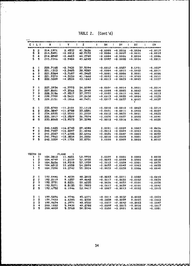
TABLE 2. (Cont'd)
CDIi X I Y 1 Z I DX I DY I DZ I •N
5 2 214.19¶1 0.4532 41.5636 -0.0009 -0.0016 -0.0004 -0.00M95 3 214.5491 -0.0012 42.9172 -0.0004 -0.0009 -0.0001 -0.00105 4 214.8949 -0.4683 44.2709 -0.0004 -0.0006 0.0004 -0.00065 5 215.R316 -0.9484 45.6245 -0.0007 -0.0008 -0.0004 -0.0011
6 1 220.7165 -2,7430 37.5094 -0.0012 -0,0927 0.0(01 -0.00296 2 221.1303 -3.2485 38.9287 -0.0004 -0.0010 -0.0002 -0.00116 3 221.5364 -3,7687 40.3465 -0.0001 -0.0006 0.0001 -0.00066 4 221.9370 -4,3033 41.7'660 -0,0003 -0.0011 -0.0.00 -0.00116 5 222.3309 -4.8534 43.1843 -0.0013 -0.0023 -0.0005 -0.0027
7 1 227.3934 -6.7773 34.8099 -0.0001 -0.0014 0,000l -0,00147 2 227.8601 -7.3566 36.2949 -0.0008 -0.0005 0.0002 -C.00087 3 228.3186 -7.9517 37.7777 -0.0005 -0.0012 -0.000: -0.00137 4 228.7709 -8.5631 39.2638 -0.0013 -0,0025 -0.0004 -0.00287. 5 229.2151 -9.1866 40.7471 -0.0017 -0.00.7 0.90(15 -0.003?
8 1 233.8700 -11.2181 32.1118 -0.0010 -0.0010 -0,0003 -0,00146 2 234.3847 -11.8788 33.6581 -0.0001 -0.0011 0.0000 -0.00098 3 234.8925 -12.5592 35.2059 -0.0042 -0.0020 -9.0001 -0.0023
8 4 235.3917 -13.2529 36.7574 -0.002O -0.0037 0.0000 -0.00418 5 235.8865 -13.9573 38.3098 -0.0012 -0.0016 0.00CI -0.0020
9 1 240.1425 -16.0743 29.4080 0.0001 -0.0009 0.0003 -0.00069 2 240.7007 -16.8297 31.0240 -0.0013 -0.0024 -0.0003 -0.00269 3 241.2507 -17.6005 32.6416 -0.0026 -0.0047 -0.0000 -0.00529 4 241.7960 -18.3834 34.2556 -0.0010 -0.0028 0.0001 -0.00279 5 242.3359 -19.1750 35.8751 0.0008 0.0009 0.0000 0.0012
TOOTH 30 FLANK I1 1 184.3812 11.4651 5.0.9900 0.0009 0.0006 0.0000 0.00081 2 184.4749 11.2009 52.0935 -0.0003 -0.0008 0.0000 -0.00081 3 184.5656 10.9318 53.1939 -0.0012 -0.0028 -0.0001 -0.00301 4 184.6512 10.6558 54.2890 -0.0023 -0.0049 -0.0003 -0.00531 5 184.7290 10.3742 55.3824 -0.0020 -0.0038 0.0006 -0.0040
2 1 192.0446 9.4230 48.3015 -0.0003 -0.0011 0.0002 -0.00102 2 192.2119 9.1257 49.4642 -0.0017 -0.0030 -0.0002 -0.00342 3 192.3731 8.8231 50.6235 -0.0026 -0.0053 -0.0001 -0.00582 4 192.5271 8.5135 51.7822 -0.0017 -0.0039 -0.0001 -0.00422 5 192.6752 8,1946 52.9417 -0.0007 -0.0013 -0.0002 -0.0015
3 1 199.5096 6.9746 45.6071 -0.0014 -0.0032 0.0002 -0.00343 2 199.7430 6.6385 46.8330 -0.3028 -0.0059 0.0005 -0.00633 3 199.9674 6.2971 48.0532 -0.0022 -0.0042 -0.0003 -0.00473 4 200.1882 5.9430 49.2788 -0.0009 -0.0015 --0.0000 -0.00173 5 200.4059 5.5768 50.5046 -0.0000 -0.0001 0.0002 -0.0001
34
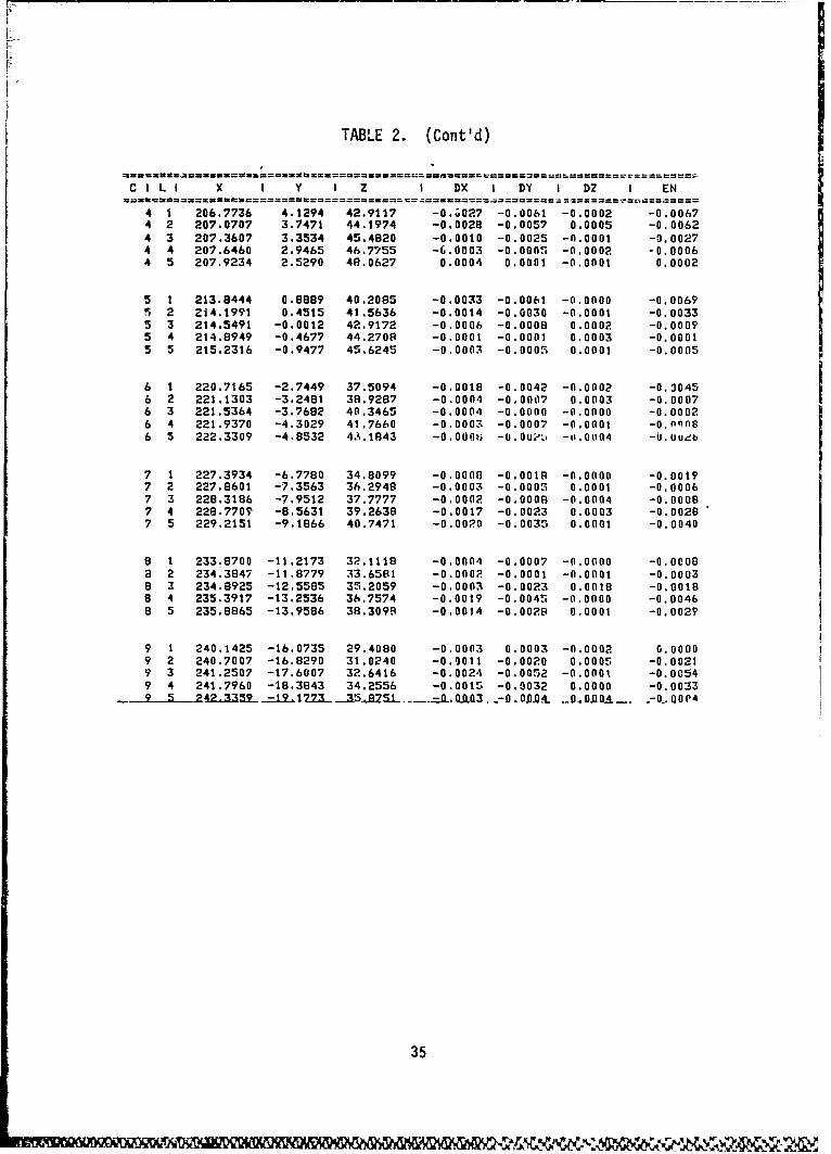
TABLE 2. (Cont'd)
C I L I X I Y I Z I DX I DY I DZ I EN
4 1 206.7736 4.1294 42.9117 -0.;027 -0.0061 -0.0002 -0.00674 2 207.0707 3.7471 44.1974 -0.0028 -0.0057 0.0005 -0.00624 3 207.3607 3.3534 45.4820 -0.0010 -0.0025 -0.0001 -0.00274 4 207.6460 2.9465 46,7755 -6.0003 -0.0005 -0.0002 -0.00064 5 207.9234 2.5290 48.0627 0.0004 0.0001 -0.0001 0.0002
5 1 213.8444 0.8889 40.2085 -0.0033 -0.0061 -0.0000 -0.00695 2 214.1991 0.4515 41.5636 -0.0014 -0.0030 -0.0001 -0,00335 3 214.5491 -0.0012 42.9172 -0.0006 -0.0008 0.0002 -0.00095 4 214.8949 -0.4677 44.270S -0.0001 -0.0001 0.0003 -0.00015 5 215.2316 -0.9477 45.6245 -0.0003 -0.0005 0.0001 -0.0005
6 1 220.7165 -2.7449 37.5094 -0.0018 -0.0042 -0.0002 -0.90456 2 221.1303 -3.2481 38.9287 -0.0004 -0.0007 0.0003 -0.00076 3 221.5364 -3.7682 40.3465 -0.0004 -0.0000 -0.0000 -0.00026 4 221.9370 -4.3029 41.7660 -0.0003 -0.0007 -0.0001 -O.nfnB6 5 222.3309 -4.8532 43.1843 -0.000t, -0.00*, -uo.0004 -O.oueb
7 1 227.3934 -6.7780 34.8099 -0.0008 -0.0018 -0.0000 -0.00197 2 227.8601 -7.3563 36.2948 -0.0003 -0.0005 0.0001 -0.00067 3 228.3186 -7.9512 37.7777 -0.0002 -0.0008 -0.0004 -0.00087 4 228.770T -8.5631 39.2638 -0.0017 -0.0023 0.0003 -0.00287 5 229.2151 -9.1866 40.7471 -0.0020 -0.0035 0.0001 -0.0040
8 1 233.8700 -11.2173 32.1118 -0.0004 -0.0007 -0.0000 -0.00088 2 234.3847 -11.8779 33.6581 -0.0002 -0.0001 -0.0001 -0.00038 3 234.8925 -12.5585 35.2059 -0.0003 -0.0023 0.0018 -0.00188 4 235.3917 -13.2536 36.7574 -0.0019 -0.0045 -0.0000 -0.00468 5 235.8865 -13.9586 38.3098 -0.0014 -0.0028 0.0001 -0.0029
9 1 240.1425 -16.0735 29.4080 -0.0003 0.0003 -0.0002 0.00009 2 240.7007 -16.8290 31.0240 -0.0011 -0.0020 0.0005 -0.00219 3 241.250? -17.6007 32.6416 -0.0024 -0.0052 -0.0001 -0.00549 4 241.7960 -18.3843 34.2556 -0.0015 -0.0032 0.0000 -0.0033
-1 3-D .0,DA0A 0..00P4
35
Discussion of Results
The improved measurement process for spiral bevel gears was succes. fullydemonstrated using the Zeiss UMM 500 Coordinate Measuring Machine fitted withthe Rotary Table. The gear set up and measurement process was accomplishedeasily and quickly with excellent repeatability. The total savings ininspection and grinding time is estimated to be 7 3/4 hours per gear.
As expected, the tooth profiles of the teeth on the master pinion and gearshowed little deviation from the reference master tooth. The maximum deviationranged from 4-.00009 to -. 00015 for the pinion with corresponding values +.00005and -. 00032 for the gear.
Correlation with Taped Pa..terns
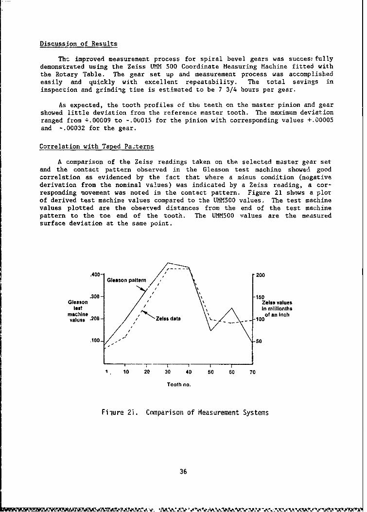
A comparison of the Zeiss readings taken on the selected master gear setand the contact pattern observed in the Gleason test machine showed goodcorrelation as evidenced by the fact that where a minus condition (negativederivation from the nominal values) was indicated by a Zeiss reading, a cor-responding movement was noted in the contact pattern. Figure 21 shows a plotof derived test machine values compared to the UMMS00 values. The test machinevalues plotted are the observed distances from the end of the test machinepattern to the toe end of the tooth. The UMM500 ivalues are the measuredsurface deviation at the same point.
.400- 200Gleason pattern 7
.300 "150Gleason / Zeiss values
test , In millionthsmachine of an Inchvalues .200 Zeiss data __ - _ 100
.100/- -s0
10 20 30 40 50 60 70
Tooth no.
Filure 2i. Comparison of Measurement Systems
36
Comparison of Nominal Values
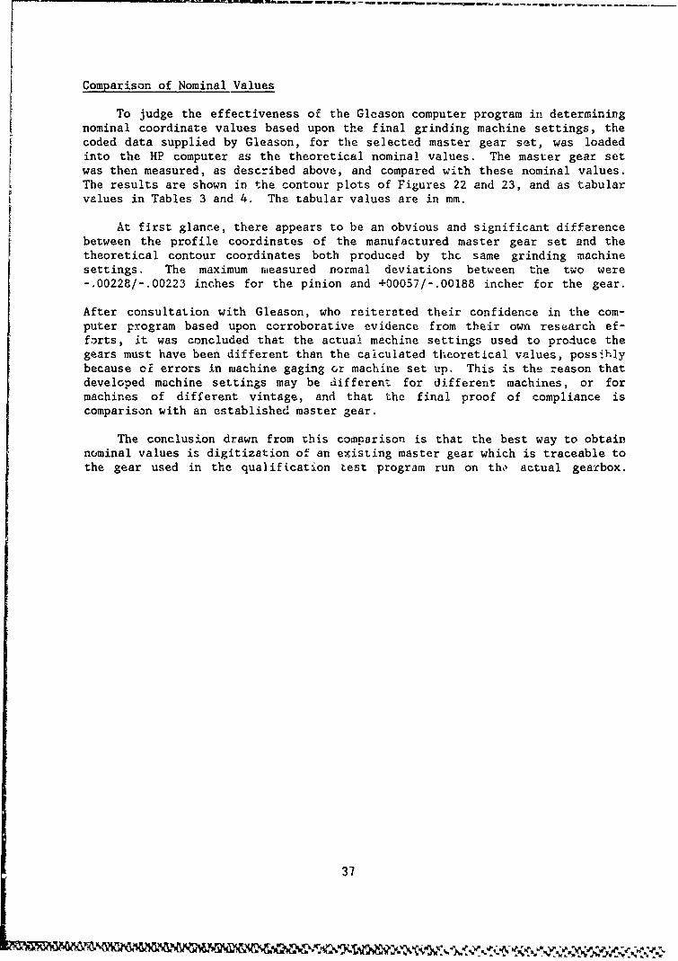
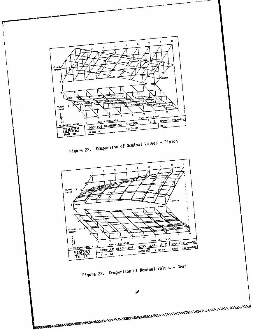
To judge the effectiveness of the Gleason computer program in determiningnominal coordinate values based upon the final grinding machine settings, thecoded data supplied by Gleason, for the selected master gear set, was loadedinto the HP computer as the theoretical nominal values. The master gear setwas then measured, as described above, and compared with these nominal values.The results are shown in the contour plots of Figures 22 and 23, and as tabularvalues in Tables 3 and 4. The tabular values are in mm.
At first glance, there appears to be an obvious and significant differencebetween the profile coordinates of the manufactured master gear set and thetheoretical contour coordinates both produced by the same grinding machinesettings. The maximum measured normal deviations between the two were-. 00228/-.00223 inches for the pinion and +00057/-.00188 inchec for the gear.
After consultation with Gleason, who reiterated their confidence in the com-puter program based upon corroborative evidence from their own research ef-forts, it was concluded that the actual machine settings used to produce thegears must have been different than the calculated theoretical values, possihlybecause cf errors in machine gaging or machine set up. This is the reason thatdeveloped machine settings may be different for different machines, or formachines of different vintage, and that the final proof of compliance iscomparison with an established master gear.
The conclusion drawn from this comparison is that the best way to obtainnominal values is digitization of an existing master gear which is traceable tothe gear used in the qualification Lest program run on th, actual gearbox.
37
loc k 0 p pItN 4 I O N ~
AL' ýnO IL 0 E SU I MEASURI N O I DA
Figure 22, ComparisOfl of Nominal Values
- Gearo
2 4 37

TABLE 3. CONPARISON OF NOMINAL VALUES-PINION
MEASURE RECORD ZEISS RAM 2DPINION 08104-45
DRAWING NO I PART NO I ORDER NO ISUPPLIER/CUSTOKERI OPERATIONP1 I T-15 I NA I SIKORS9Y I INSP FLANK
OPERATOR I DATEO'DONNELL 19n90
C I L I X I Y I z I DX I DY I DZ I EN
ALIGNMENT MODE 0 MOUNTING DIST. DmG = 269.2400TOOTH I FLANK 1
1 1 38.5027 0.6225 -197.8195 -0.0002 0.0175 -0.0003 0.01641 2. 39.3178 0.4587 -197.6658 -0.0002 0.0526 0.0004 0.04791 3 40.4567 0.0585 -197.4371 0.0001 0.0585 0.0000 0.0o.211 4 41.8490 -0.5930 -197.1430 -0.0001 0,0679 0.0000 0.05791 5 43.4264 -1.5361 -196.7924 -0.0000 0.0700 0.0002 0.0567
2 1 39.7209 2.9056 -204.6607 -0.0002 0.0027 -0,0003 0,002,2 2 40.5999 2.7663 -204.4886 -0.0020 0.0367 0.0000 0.0?342 3 41.8158 2.4043 -204.2417 -0.0024 0.0473 -0.0001 0.04162 4 43.2988 1.7885 -203.9302 -0.0028 0.0520 -u.0001 0.04372 5 44.9801 0.8929 -203.5630 -0.0029 0.0572 0.0002 0.0459
3 1 40.7552 5.4945 -211.3789 0.0010 -0.0092 -0.000i -0.00853 2 41.6974 5.3893 -211.1907 -0.05029 0.V235 0.04 • .02133 3 42.9902 5.07n9 -210.9282 -0.0037 0.0309 -0.0002 0.02683 4 44.5645 4.5122 -210.6019 -0.0048 0.e372 -0.0002 0,03083 5 46,3515 3.6817 -210.2209 -0.0056 0 0466 -0.0000 0.036e
4 1 41.5641 8.3641 -217.9704 0.0037 -0,0207 -0.0000 -0.01964 2 42.5677 8.2993 -217.7683 -0.0013 0.0063 -0.0000 0.00564 3 43.9357 8,0435 -217.4926 -0.0030 0.0159 -0.0006 0.01374 4 45,6000 7.5590 -217,1542 -0.0046 0.0253 0.0001 0 02104 5 47'4925 6.9011 -216.7619 -0,0053 0.0285 -0,0991 0.0223
5 1 42.1073 11.4823 -224.4317 0,0090 -0,0363 -0.0003 -0.03345 2 43.1695 11,4761 -2?4,2180 0.0020 -0.0091 0.0001 -0,00725 3 44.6092 11.29Z7 -223.9315 0.0001 0.0001 0.000t 0.00015 4 46.3601 10.8907 -223.5S31 -0.0012 0.0052 -0.0000 0.00435 5 48.3552 10.2352 -223.1622 -4.0036 0.0139 0.0003 9.011
6 1 42.3471 14.B250 -230.7594 0.0140 -0.0477 -0.0002 -0.04406 2 43.4639 14.8853 -230.5359 O.606b -0.0Z08 0.0001 -0.01866 3 44.9700 14.7831 -230.2408 0.0063 -G,0189 -6.0091 -0.01646 4 46.8019 14.4970 -229.S949 0.0033 -0.0106 -0.0001 -0.00886 5 48.8941 13,942S -239.4777 0.000 -0.01059 -,.0001 -0.0047
7 1 42.2488 18,3481 -236.9502 0.0246 -0 0621 0.00Q -0.05727 2 43.4148 18.4831 -236.7186 0.01i.5 -0.0393 -0.0000 -0.03557 3 44.9804 19.4865 -21-.4168 0.0127 -0.0315 0.0I00 -0.02747 4 46.953 10.3006 -Z3&.ýUSS 0.0125 -0.0319 0.c001 -0.02587 5 49.0664 11.893L -235.6446 0.0096 -0.0214 0.0000 -0.0169
8 A 1.7819 ? 2.0162 -243.0007 ii.0165 -0.0719 0.000! -0.067k
3 . "-
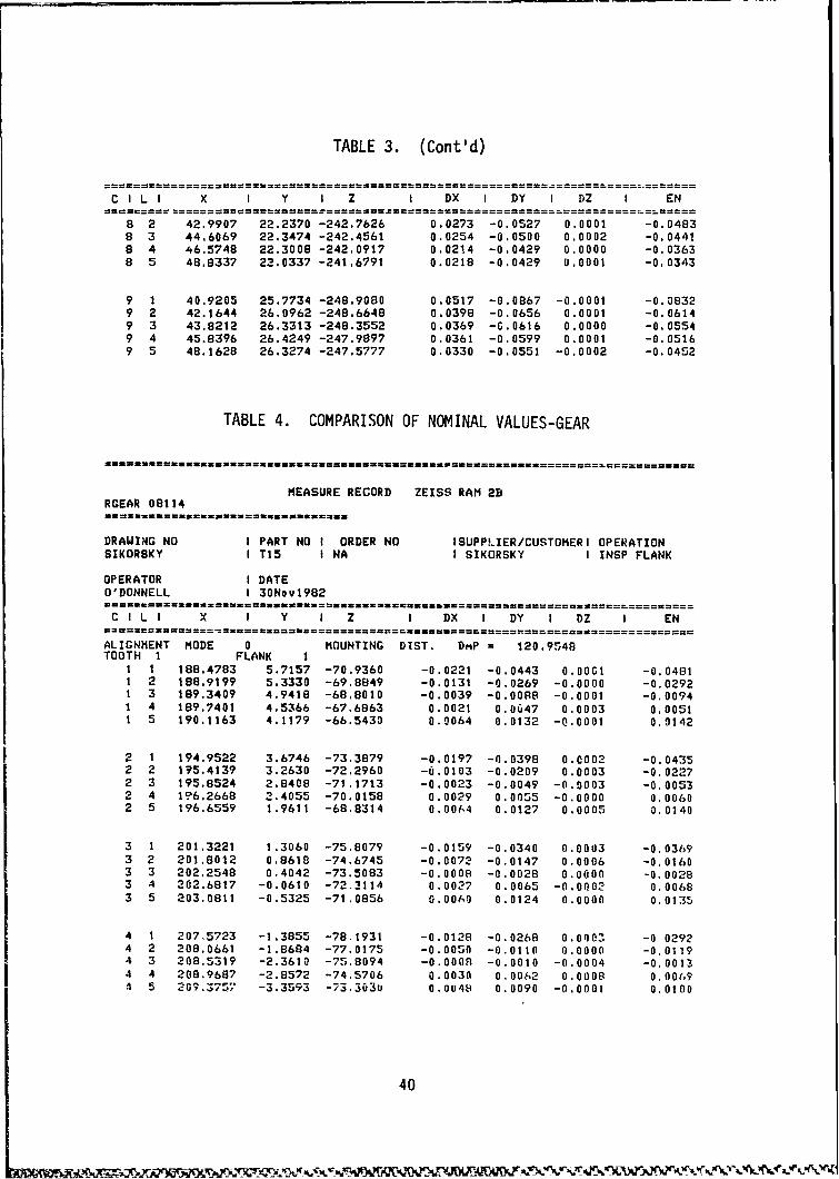
TABLE 3. (Cont'd)
CILI X I Y I Z I DX I DY I DZ I EN
8 2 42.9907 22.2370 -242.7626 0.0273 -0.0527 0.0001 -0.04838 3 44.6069 22.3474 -242.4561 0.0254 -0.0500 0.0002 -0,04418 4 46.5748 22.3008 -242.0917 0.0214 -0.0429 0.0000 -0.03638 5 48.8337 22.0337 -241.6791 0.0218 -0.0429 0.0001 -0.0343
9 1 40.9205 25.7734 -248.9080 0.0517 -0.0867 -0.0001 -0.08329 2 42.1644 26.0962 -248.6648 0.0398 -0.0656 0.0001 -0.06149 3 43.8212 26.3313 -248.3552 0.0369 -G.0616 0.0000 -0.05549 4 45.8396 26.4249 -247.9897 0.0361 -0.0599 0.0001 -0.05169 5 48.1628 26.3274 -247.5777 0.0330 -0.0551 -0.0002 -0.0452
TABLE 4. COMPARISON OF NOMINAL VALUES-GEAR
MEASURE RECORD ZEISS RAM 2BRGEAR 08114
DRAWING NO I PART NO I ORDER NO ISUPPLIER/CUSTOMERI OPERATIONSIKORSKY I T15 I NA I SIKORSKY I INSP FLANK
OPERATOR I DATEO'DONNELL I 30Nov1982
C I L I X I Y I Z I DX I DY I DZ I EN
ALIGNMENT MODE 0 MOUNTING DIST. DmP 120.9548TOOTH 1 FLANK I
1 1 188.4703 5.7157 -70.9360 -0.0221 -0.0443 O.OOG1 -0.04811 2 188.9199 5.3330 -69.8849 -0.0131 -0.0269 -0.0000 -0.02921 3 189.3409 4.9418 -68.8010 -0.0039 -0.0088 -0.0001 -0.00941 4 189.7401 4.5366 -67.6863 0.0021 0.0647 0.0003 0.00511 5 190.1163 4.1179 -66.5430 0.0064 0.0132 -0.0001 0.1142
2 1 194.9522 3.6746 -73.3879 -0.0197 -0.0398 0.C002 -0.04352 2 195.4139 3.2630 -72.2960 -0.0103 -0.0209 0.0003 -0.02272 3 195.8524 2.8408 -71.1713 -0.0023 -0.0049 -0.0003 -0.00532 4 1?6.2668 2.4055 -70.0158 0.0029 0.0055 -0.0000 0.00602 5 196.6559 1.9611 -68.8314 0.0064 0.0127 0.0005 0.0140
3 1 201.3221 1.3060 -75.8079 -0.0159 -0.0340 0.0003 -0.03693 2 201.8012 0.8618 -74,6745 -0.0072 -0.0147 0,0006 -0.01603 3 202.2548 0.4042 -73.5083 -0.0008 -0.0028 0.0000 -0.00283 4 202.6817 -0.0610 -72.3114 0.0027 0.0065 -0.0002 0.00683 5 203.0811 -0.5325 -71.0856 0.0060 0.0124 0.0000 0.0135
4 1 207,5723 -1.3855 -78.1931 -0.0128 -0.0268 0.Oe00 -0 02924 2 208.0661 -1.8684 -77.0175 -0.0050 -0.0110 0.0000 -0.01194 3 208.5319 -2.3610 -75.8094 -0.0008 -0.0010 -0.0004 -0,00134 4 208.9687 -2.8572 -74.5706 0.0030 0.0062 0.0008 0.00(69S5 209.3757 -3.3593 -73.303u 0.0048 0.0090 -0.0001 0.0100
40
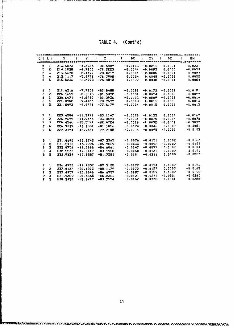
TABLE 4. (Cont'd)
C ILI X I Y I Z I DX I DY I DZ I EN
5 1 213.6873 -4.3965 -80.5409 -0.0103 -0.0211 0.0001 -0.02315 2 214.1928 -4.9200 -79.3225 -0.0044 -0.0085 0.0003 -0,00935 3 214.6678 -5.4477 -78.0719 0.0001 -0.0005 -0.0001 -0.00045 4 215.1117 -5.9771 -76.7908 0.0024 0.0048 -0.0002 0.00525 5 215.5236 -6.5098 -75.4812 0.0027 0.0048 -0.0001 0.0054
6 1 219.6516 -7.7206 -82.8488 -0.0090 -0.0172 -0.0001 -0.01916 2 220.1657 -8.2843 -81.5872 -0.0030 -0.0074 -0.0002 -0.00776 3 220.6471 -8,8490 -80.2936 -0.0003 -0.0009 -0.0002 -0.00106 4 221.0952 -9.4135 -78.9699 0.0000 0.0011 0.0002 0.00136 5 221.5092 -9.9771 -77.6179 -0.0004 -0.0015 0.0008 -0.0013
7 1 225.4504 -11.3491 -85.1147 -J.0076 -0.0155 0.0004 -0.01677 2 225.9699 -11.9546 -83.8094 -1.0031 -0.0075 -0.0004 -0.00787 3 226.454C -12.5574 -82.4724 -0.n018 -0.0032 -0.0001 -0.00377 4 226.9039 -13.1580 -81.1056 -0.bl24 -0.0046 -0.0002 -0.00517 5 227.3174 -13.7530 -79.7108 -0.0014 -0.0096 -0.0001 -0.0103
8 1 231.0690 -15.2742 -87.3365 -0.0076 -0.0151 0.0002 -0.01638 2 231.5906 -15.9226 -85.9869 -0.0048 -0.0096 -0.0002 -0.01048 3 232.0756 -16.5666 -84.6061 -0.0047 -0.0097 -0.0002 -0.01048 4 232.5233 -17.2019 -83.1958 -0.0060 -0.0137 0.0009 -0.01418 5 232.9334 -17.8287 -81.7580 -0.0101 -0.0211 0.O000 -0.0223
9 1 236.4932 -19.4857 -89.5122 -0.0072 -0.0174 0.0002 --0.01769 2 237.0137 -20.1803 -88.117Y -0.0072 -0.0157 0.0003 -0.01639 3 237.4957 -20.8646 -86.6927 -0.0087 -0.0189 0.0007 -0.01959 4 237.9389 -21.5355 -85.2386 -0.0121 -0.0244 -0.0001 -0.02609 5 238.3430 -22.1919 -83.7574 -0.0162 -0.0338 -0.0001 -0.0355
41
DEVELOPMENT OF AN IN-PROCESS INSPECTION TECHNIQUE
One of the prime requirements identified at the outset for an improvedspiral bevel gear inspection method is that; if the profile deviations of aproduction gear, as measured on the coordinate measuring machine, are beyondacceptable limits; these deviations must be interpretable in terms of specificdelta changes to the grinding machine setting used to produce that gear. Theprocedure is essentially the inverse of the mathematical simulation processdescribed earlier and is accomplished by a second part of the Gleason WorksG-Age software package described below.
G-Age Corrective Process
After a spiral bevel gear set has been "developed" for operation in aparticular gearbox, the final grinding machine settings are used to calculatethe theoretical surface coordinate and normals. This information is stored inthe measuring macb'ne computer. Along with this theoretical surface data, acorrective matrix is also generated and stored. The corrective matrix can beconsidered as a surface sensitivity matrix. For example, changes that affectthe pressure angle and spiral angle of the tooth surface are defined. Thesensitivity of the surface to these changes is calculated and stored in thecorrective matrix. Changes are so defined for all Gleason cutting and grindingmethods.
When the tooth surfaces of the individual gears are measured and comparedto the nominal value matrix (either calculated theoretical surface points ormeasured surface points from a master gear), a matrix of error data is computedand stored. The error data is then multiplied by the corrective matrix andcorrective settings for the grinding machine are calculated and printed out.
Sensitivity Study
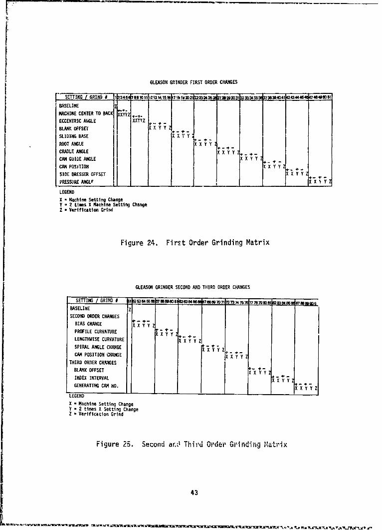
To evaluate this in-process inspection technique, which will convertreadings from the Zeiss UMM500 measuring machine into precise settings for thespiral bevel gear grinding machine, a sensitivity study was made ip which geartest specimens were ground and reground with machine settings that purposelydeviated from the developed summary settings according to the matrices ofFigures 24 and 25. This study involved 10 first order changes and 8 second andthird order changes for the pinion and 10 first order changes for the gear.Each setting change consisted of 5 variations including one baseline, for atotal of 91 grinds for the pinion and 51 grinds for the gear.
Fabrication of Test Gear Specimens
The 10 pinion test specimens and 5 gear test specimens, which weremachined in Phase I, were ground according to the grinding matrix of Figure 24and 25. For each setting, two deviations above and two deviations below theestablished values were used. When all of the grinds at one machine settingwere completed, a verification grind was made to reestablish the baselincsettings before proceeding on to the next machine setting.
42
I... ~~ ~ ~ ~fl ~ nflfYY~~W¶ Sr SA - -r -B -r -n -n -n -n -.. p-. rfstiA .-
GLEASON GC{NDER FIRST ORDER CHANGES
SETTING /GRIND 245 ___M~ 1234616B 7 D 22M2426 2 2672807 1 32337374 5 30379363r 4123444 47484DD5
BASELINE z
MACINE CENTR TO BACKI rX'XYZ ,,ECCENTRIC NGLE E XXYYZ fS +BLANK OFFSET X X yi YY
SLIDING BASE - X
ROOT ANGLE X X Y Y -
CRLEANGE E X X Y Y 2+C GUIDE ANGLE X X Y YxzCAM POSITION X X Y YH
SIDE DRESSER OFFSET X X Y Y
PRESNS E A CL A NOI X I YxZLEGEND
X - Machine Setting ChangeY - 2 times X Machine Setting ChangeZ - Verification Grind
Figure 24. First Order Grinding Matrix
GLEASON GRINDER SECOND AND THIRD ORDER CHANGES
[ SETTING / GRIND # -66srsmse~m ee •7• ol •s3e4e6eee7Oe0e70o• 737475•ST7778798OW283848, Lp~gmBASELINEZ
SECOND ORDER CHANGESBIAS CHANGE X" ÷-yPROFILE CURVATURE Y Y 2+-
Y3
LENGTHWISE CURVATURE X • ÷"SPIRAL ANGLE CHANGE "+y zCAN POSITION CHANGE X X Y Y 2
THIRD ORDER CKLPAAGESBLANK OFFSET + "X X• " YIND EX INTERVAL -X 'Y -YGENERATING CAM NO. Z
LEGEND
X - Machine Setting ChangeY - 2 times X Setting ChangeZ - Verification Grind
Figure 25. Second ar.v' Thir-d Order Grinding " .... -"
43
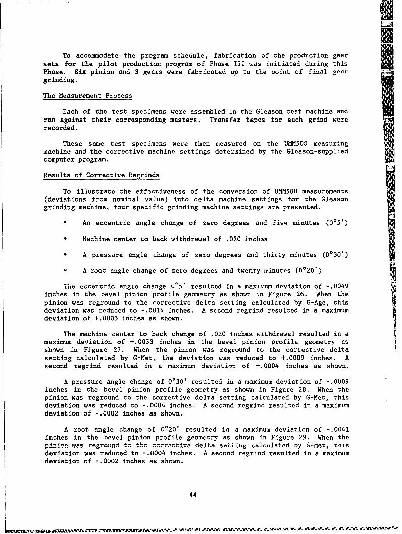
UTo accommodate the program schediule, fabrication of the production gear
sets for the pilot production program of Phase III was initiated during thisPhase. Six pinion and 3 gears were fabricated up to the point of final reargrinding.
The Measurement Process
Each of the test specimens were assembled in the Gleason test machine andrun against their corresponding masters. Transfer tapes for each grind wererecorded.
These same test specimens were then measured on the UMM500 measuringmachine and the corrective machine settings determined by the Gleason-suppliedcomputer program.
Results of Corrective Regrinds
To illustrate the effectiveness of the conversion of UMM500 measurements(deviations from nominal value) into delta machine settings for the Gleasongrinding machine, four specific grinding machine settings are presented.
"* An eccentric angle change of zero degrees and five minutes (005')
"* Machine center to back withdrawal of .020 inchas
"• A pressure angle change of zero degrees and thirty minutes (0030')
"0 A root angle change of zero degrees and twenty minutes (0020")
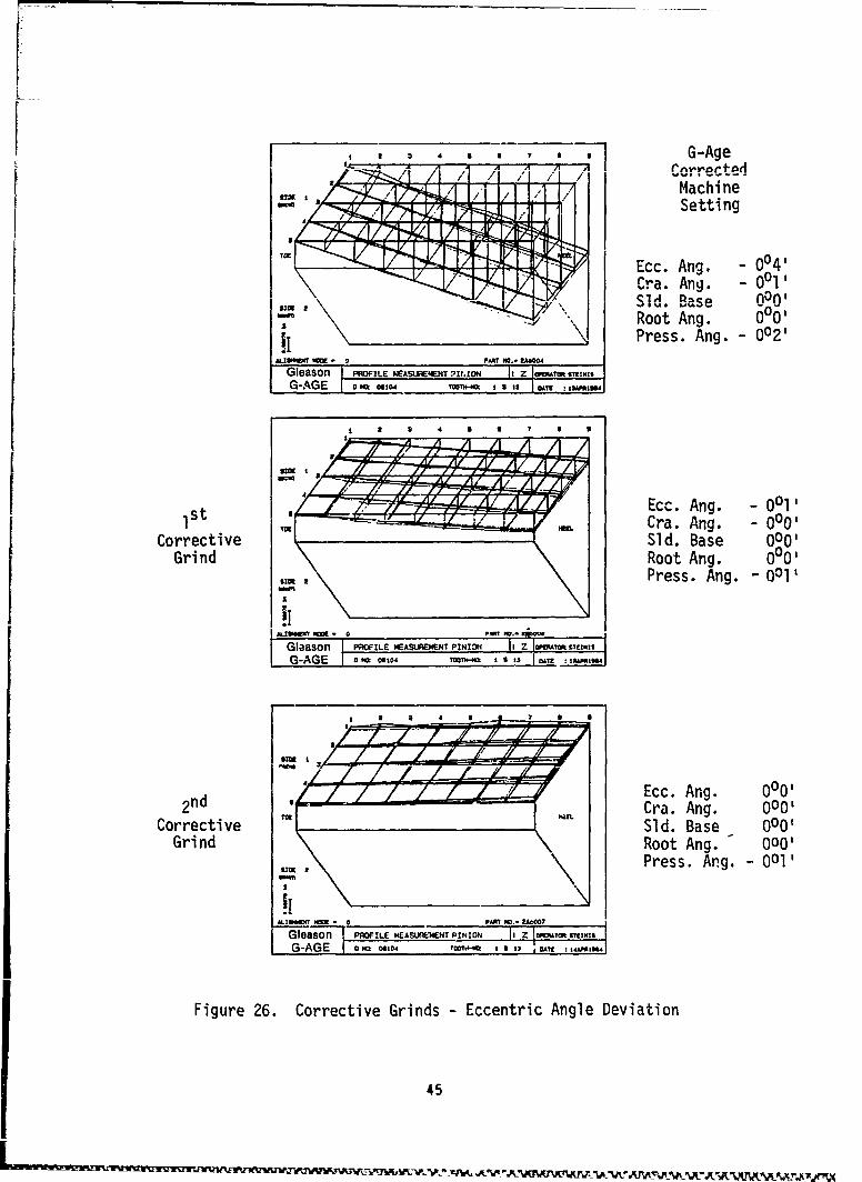
The eccentric angle change 0U5* resulted in a maxiLum deviation of -. 0049inches in the bevel pinion profile geometry as shown in Figure 26. When thepinion was reground to the corrective delta setting calculated by G-Age, thisdeviation was reduced to -. 0014 inches. A second regrind resulted in a maximumdeviation of +.0003 inches as shown.
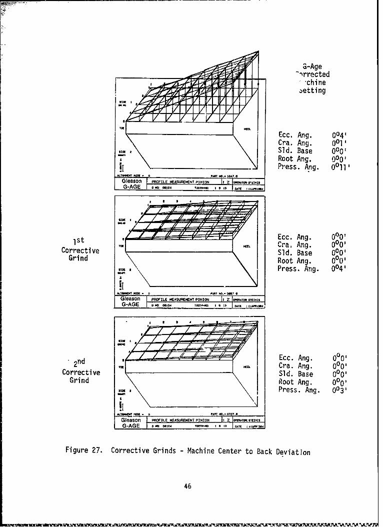
The machine center to back change of .020 inches withdrawal resulted in amaximum deviation of +.0053 inches in the bevel pinion profile geometry asshown in Figure 27. When the pinion was reground to the corrective deltasetting calculated by G-Met, the deviation was reduced to +.0009 inches. Asecond regrind resulted in a maximum deviation of +.0004 inches as shown.
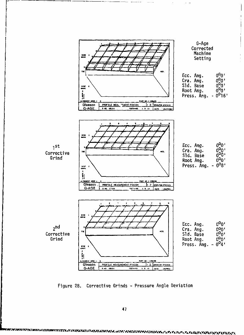
A pressure angle change of 0030' resulted in a maximum deviation of -. 0009inches in the bevel pinion profile geometry as shown in Figure 28. When thepinion was reground to the corrective delta setting calculated by G-Met, thisdeviation was reduced to -. 0004 inches. A second regrind resulted in a maximumdeviation of -. 0002 inches as shown.
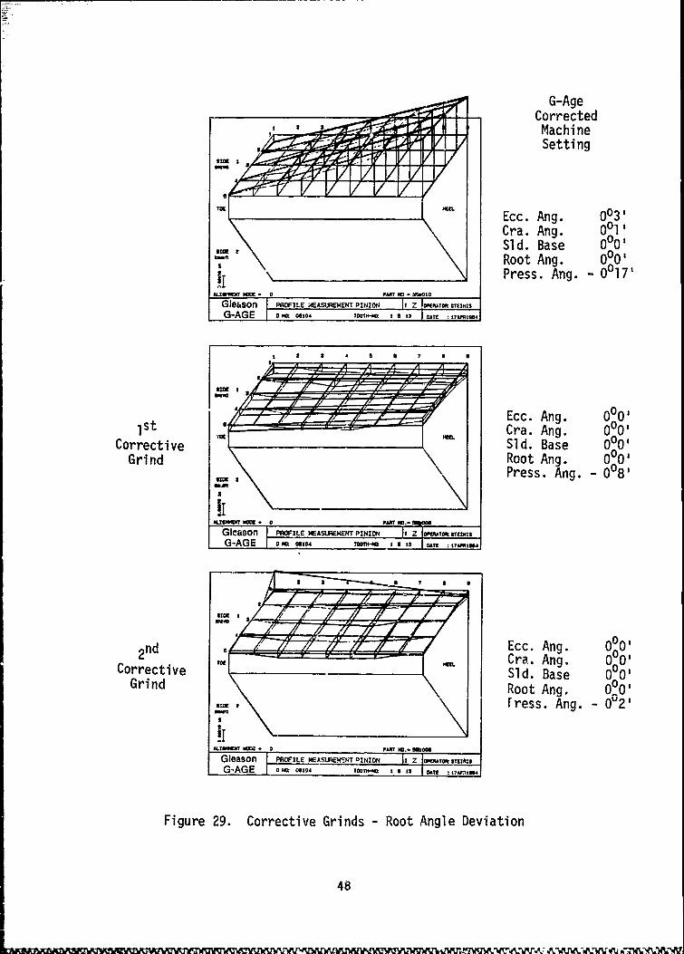
A root angle change of 0020' resulted in a maximum deviation of -. 0041inches in the bevel pinion profile geometry as shown in Figure 29. When the
----- was...------ Ctor.edile setttig calculated by b-Met, thisdeviation was reduced to -. 0004 inches. A second regrind resulted in a maximumdeviation of -. 0002 inches as shown.
44
, 4 9 8 , , , 9 G-Age
,/ •/ / MachineSetting
Ecc. Ang. - 004'Cra. Ang. - 0011SSld. Base 0on'"Root Ang. 0°00Press. Ang. - 002'
ALI~mEW N• • 0PAMl NO,- 2004
Gleason I PROFILE WASUREET It.IN It _ z7 MTMG-AGE o. Nml oe T 't* " 1 = 9 13 DA
SEcc. Ang. - 0011Ist- " " -Cra. Ang. - 0001
Corrective Sld. Base 000,Grind Root Ang. 000
Press. Ang. - 001'
| G-oAGE PROILE M4EASUREMIENT PINION Jtz .•:sN,
Ecc. Ang. 0°002nd Cra. Ang. 000'
Corrective Sld. Base 0Q00Grind Root Ang. - 000'
Sim Press. Ang. -001'
!iALINS.T 1W - pAWl NO., .U0007
Gleason PROF'LE MEAS NE'WNT PINION I , Z jIsE&T. TI IIS
G-AGE o mm 041o0 TT4 1 1- ' I ' i : 1"3
Figure 26. Corrective Grinds - Eccentric Angle Deviation
45
ZG-AgeThrrected
'chineaetti ng
Ecc. Mng. 0041Cra. Ang. 0015
SM2SId. Base 0001Root Ang. 0001
IjPress. ANg. 0011.ALIU~a ft * 0PAW? NO.- 1"7.6
Gleason [PROFILE MEASUREMENT PINION If Z I wEAM? s'rNISr "G0-AGfiiE 1 0 tQ 010 VOIWi@ 5 13 1W I1"
stEcc. Ang. Q00!
Cr.a . Ang. 0005Corrective 'Sid. Base 00Grind Root Ang. 0001
Nic IPress. Ang. 0041
Gleiason IPROFILE NEASURE;ENT PINION 11 Z fA LtrI
G-AGE 1 Ma 40 TeQf I 3 1DA IM
-4iEcc. Ang. 00052nd TM Cra. Ang. 00
Corrective SId. Base 00Grind Root Ang. 00O01
Press. Ang. 003'
TG m TPg O-0c.leaSOn- POFILE MEASUREMENT PINION =h :Zý Vrai~IM.
Figure 27. Corrective Grinds - Machine Center to Back Deviation
46
- ~ . ~~1~t W~ W ~U .P .IU~W,2S.?-~JB0 ~ Z W FLUS .
-A ,r G-AgeCorrectedMachineSetting
Ecc. Ang. 0°00Cra. Ang. 0001
SSid. Base 0001
5 Root Ang. 000'1 FPress. Ang. 00161
GPROn FI L HEALu .{, •.NT pIjNION_ It Z lW,' ftVI-I
- 0AG a 1TOOH-.* 1 2 13
1tEcc. Ang. 0001Tt "m Cra. Ang. 0001
Corrective Sld. Base 0001Grind Root Ang. 0°00
Press. Ang. - 008'
Gleason PROFILE EASUREMENT PINION T-7 -
G-AGE I , ' ,'IO-
nd Ecc. Ang. 000'I2 Cra. Ang. 000'
Corrective Sld. Base 000Grind Root Ang. 00'
Press. Ang. - 0°4'
Gleason PROFILE MEASUREHMENT N IOG IZsor* ' S(
G-AGE o so loo WE
Figure 28. Corrective Grinds - Pressure Angle Deviation
47
G-Age-Corrected
MachineSetting
,w - IEcc. Ang. 003'
Cra. Ang. 0011
Sld. Base 0001, Root Ang. 000'
__I__ _ \ Press. Ang. - 0017'IAL!U1fT Nm - 0 PART NO - bUO10
Glehson PROFILE 4EASUREMENT PINION It Z sireT OrEzNIS
G-AGE I .= Co, T•f-@ I . . 3
a 3 4 $ 6 S a 0
s Ecc. Ang. 0°00s- - •Cra. Ang. 0°00
Corrective Sld. Base 0001
Grind Root Ang. 0001Press. Ang. - 0081
U.T 8W " - 0 PART INO0.o
Gleason PROFILE MEASUREMENT PINIO zG-AGE o to o0e4 TWT 1S 5 13 00?! I7AmO,4
2nd L Ecc. Ang. 0 02 Cra. Ang. 0001
Corrective Sld. Base 0OQOGrind Root Ang. 0 °0
rress. Ang. - 0U2 '
!iALW~ pm No 0 a mEIS om0
Gleason PROFILE NEASURENcNT DINION I 1• .rEAG.AGE 0 60104 ToolT--* 1 1 1 Ayt ; £:27MMO
Figure 29. Corrective Grinds - Root Angle Deviation
48
Discussion of Results
In all four cf the above cases, the bevel pinion tooth profile geometrywas restored to within acceptable limits in two regrinds using only first orderchanges. This demonstrated that the G-Age corrective procedure is effective incorrecting an out-of-tolerance tooth profile during the production process andcan virtually eliminate the need for a final inspection process.
It will be noted that, in some cases, the correction feature of the G-Ageprogram indicated a change in more than one setting when only one was initiallydisturbed. This illustrates the fact, previously mentioned, that a combinationof two or more moves in the Gleason grinder may produce results similar to asingle move. If the correction program can be faulted, perhaps it can be saidthat it does not necessarily take the most direct path to a solution.
It should be mentioned, at this point, that the G-Age program, sophisti-cated as it is in its present form, is undergoing changes and modifications toimprove its effectiveness. Later versions, for example, will include secondorder changes as well as first order changes.
Establishment of Tolerance Limits
Based upon the results of the efforts of Phases I and II and the experi-ence accummulated of the Zeiss UMM500 multi-axis measuring maching, preliminarytolerance levels have been established for the selected BLACK HAWK bevel gearset. These are shown in Table 5. Each grid point location has a specifictolerance. If these limits are connected by straight lines the toleranceenvelope of Figure 30 is derived, this could be used in the form of a trans-parent overlay in the inspection process.
49
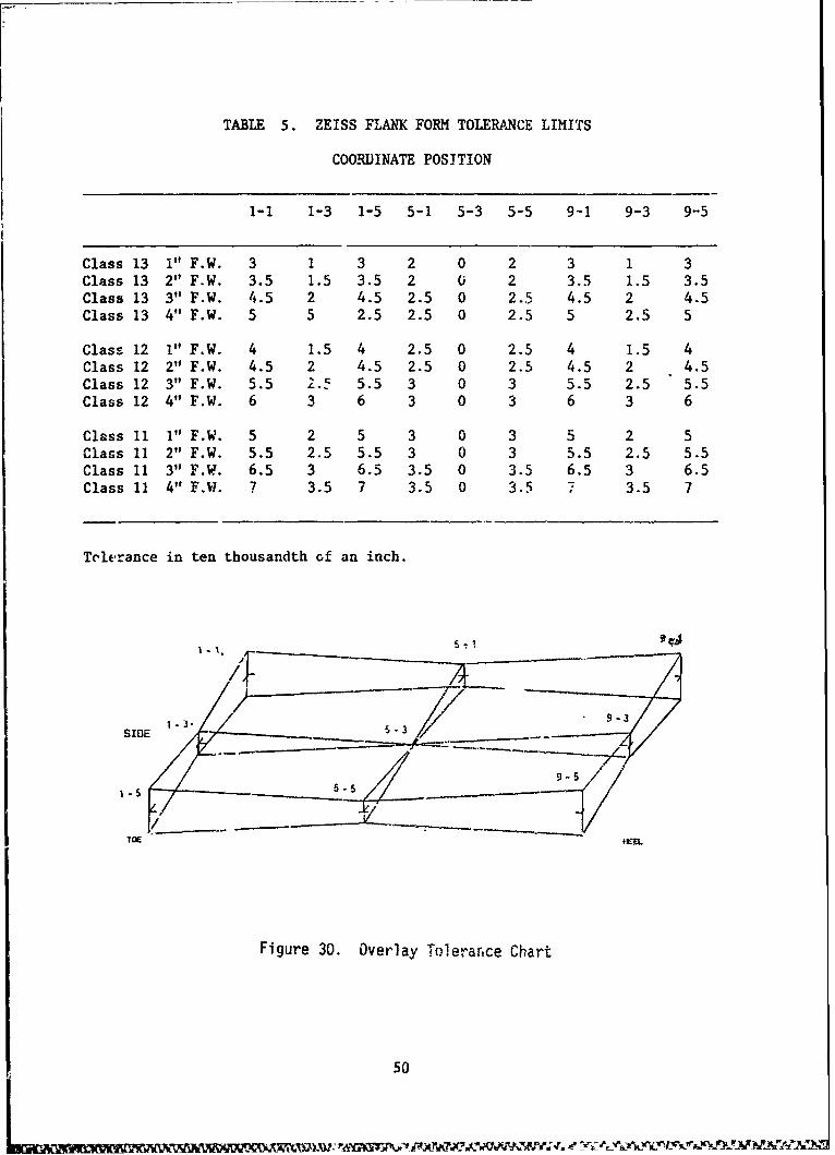
TABLE 5. ZEISS FLANK FORM TOLERANCE LIMITS
COORDINATE POSITION
1-1 1-3 1-5 5-1 5-3 5-5 9-1 9-3 9-5
Class 13 1" F.W. 3 1 3 2 0 2 3 1 3Class 13 2" F.W. 3.5 1.5 3.5 2 0 2 3.5 1.5 3.5Class 13 3" F.W. 4.5 2 4.5 2.5 0 2.5 4.5 2 4.5Class 13 4" F.W. 5 5 2.5 2.5 0 2.5 5 2.5 5
Class 12 1" F.W. 4 1.5 4 2.5 0 2.5 4 1.5 4Class 12 2" F.W. 4.5 2 4.5 2.5 0 2.5 4.5 2 4.5Class 12 3" F.W. 5.5 2., 5.5 3 0 3 5.5 2.5 5.5Class 12 4" F.W. 6 3 6 3 0 3 6 3 6
Class I1 1" F.W. 5 2 5 3 0 3 5 2 5Class 11 2" F.W. 5.5 2.5 5.5 3 0 3 5.5 2.5 5.5Class 11 3" F.W. 6.5 3 6.5 3.5 0 3.5 6.5 3 6.5Class 11 4" FW. 7 3.5 7 3.5 0 3.5 7 3.5 7
Tolerance in ten thousandth of an inch.
-----------/ _ _ ý ------
SIDE -3 /7
9-51 -5 6-5_______ ..............
TOE
Figure 30. Overlay Tolerarnce Chart
50
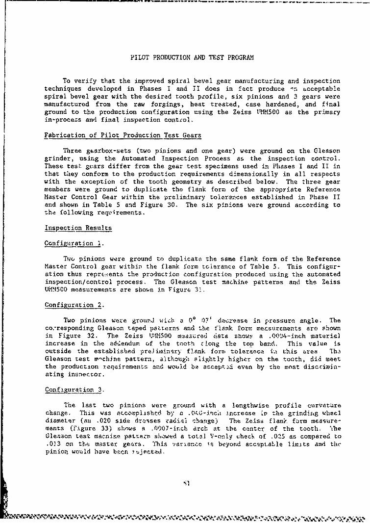
PILOT PRODUCTION AND TEST PROGRAM
To verify that the improved spiral bevel gear manufacturing and inspectiontechniques developed in Phases I and HI does in fact produce -'n a.cceptablespiral bevel gear with the desired tooth profile, six pinions and 3 g'ears weremanufactured from the raw forgings, heat treated, case hardened, and finalground to the production conf~iguration using the Zeiss 11HM500 as the primaryin-procezs and final inspection conttol.
Fabrication of Pilot Production Test Gears
Three gearbox-sets (two pinions and one gear) were ground on the Gleasongrinder, using the Automated Inspection Process as the inspection control.These test gcars differ from the gear test specimens used UiI Phases I and II inthat they conform to the production requirements dimensionally in all respectswith the exception of the tooth geometry as described below. The three gearmembers were ground to duplicate the flank form-. of the appropriate ReferenceMaster Control Gear within the preliminary tolerapces established in Phase IIand shown in Table 5 and Figure 30. The. six pinions were ground according tothe following requirements.
InspectioRn Results
ConfiguIration 1.
Two pinions were ground to duplicate the same flank form of the ReferenceMlaster Control gear within the flank form tcoierance of Table 5. This configur-ation thus reprtsents the production configuration produced using the automatedinspection/ control process. The Gleason test mar-hinte patterns and the ZeissUrIM500 measurements are shown in Figure 31.
Configuration 2.
Two pinions were ground1 wi--h a 00 ;07' decresse in pressurn angle. Theco.-responding Gleason taped psterns and~ the flank form, met~suremepnts are shownin Figure 32. The Zeiss U1'10,1500 tr~lured 6,ata zhawý; a Q0f)04-inch materialincrease in the adtdendum. of the toothi c-ong the top band. This value isoutside the established pre~inianarý flank fore: tolerrance ia this urea, lh--Gleason test w-chine pattern, althouZgh sliiý.tly high~cr on the tooth, did meetthe production requ.4rements and would bit accept-,-- even by the most discciwlin-ating insnector.
Laurt ion_3.
The last two pinio~ns were ground with a longthwise profile curv.aturechange,. This was oý.co?,plishccI by a .Q4X-~inc~o i~ncrease ý,' the grindinzg wheeldiameter (au .020 side dresses radial ;bmiuge) T1he Zeiss flankr fozrm measure-iments (Figure 33) shows q .0007-inch arch at the ce-nte-r of the tooth. ThleGle~aon test mac~nine pattern si~owed a total V-only checlk of .025 as compared to.013 _= the master gea~rs. This variance is beyond accsptahle limits and the
ppiniozn
would have
bcee-n
jetd
0ný1
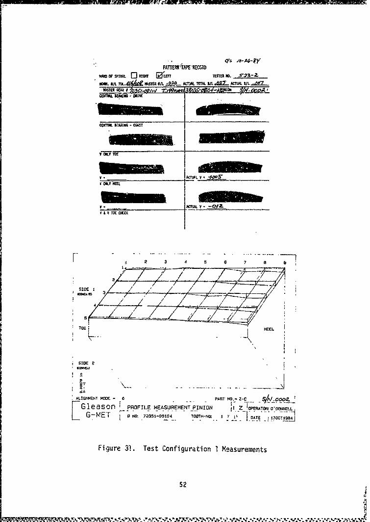
Cc�X . -TIN - KA=ST
AM. BA___4d WM_,L_0_____OTL__ tL V
V OKY MOE
V OIYHE
S& 14 TOE OCHEC
F ... ........S 2 3 7 B
5 4 7 e
SID 1 --T 7 7--k-r 7---:,,/.- / _,....• •._.
TOEE SEEL
SIDE 2
I C
ALI -"WENT MODE - 0r, PART NO.- Z-C___
Glaon PROFILE MEASUREMENTPINION 11. Z 0RAOOL.
K G-d ET P NO: 7 -351-o0.0 TOOTH-O. D . I !OATE :170Z:TI9841
Figure 31. Test Configuration 1 Measurements
52
:9• , ••.•• - •..• • •.• • w• % •.," .•. • • • .%•--r•.•. • . % . ,%. ,. . % •.;; ••..,..,-. ,a •. ,•-.••;
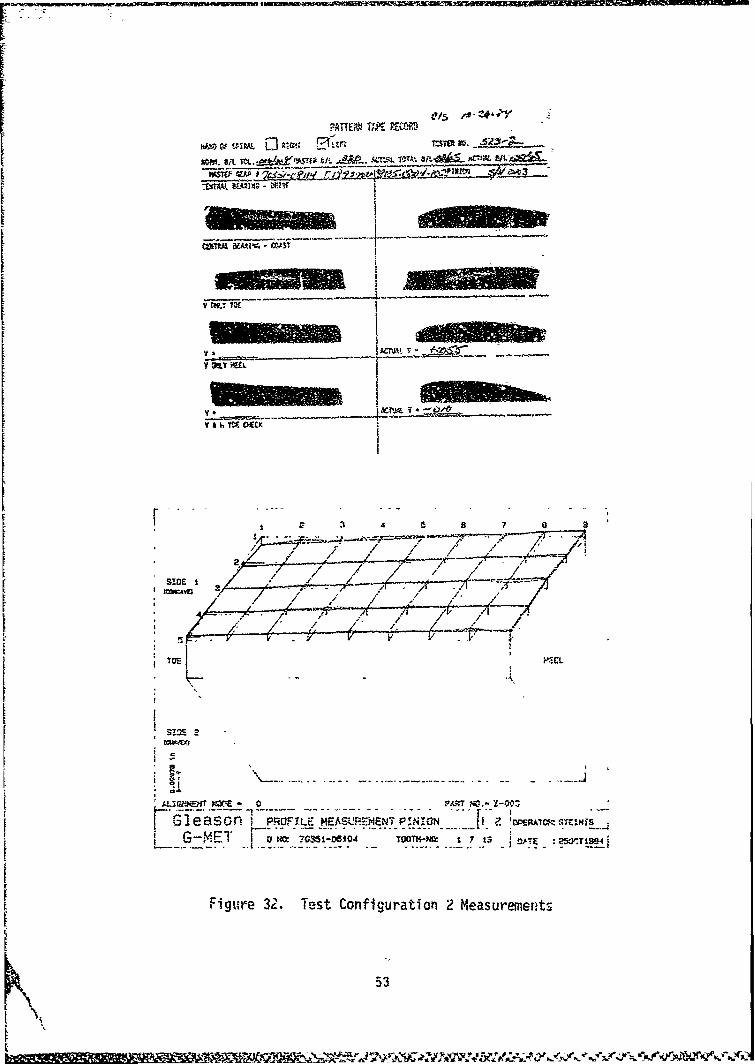
RATTE;W TAKE PEW-RD
W-10 UM, DA ANN E- I z -1 ,0._____•,-. oil 4,-AVE ti3 4'k&" ALMS-, IOA' aA .S _._• "-W -!Lx2
WSW 4w •
. ow. 10E / / / '7-- /- - / IV Au h Yf CEC
, ~ ~ ~ ~ .... ..... .. .... ./ ./ ... i2 ... ... ..........
SID I bT E
Si 2
1- MW$M- 0 PAM NO- -0:
1 -leason- PROFILE MEASUR.•i4NTP!N--3N t ' M0M-. ST.,NIK S
G F__ M2. TestConfgur TOOTn-N8 Me :asu5t T
Figu~re 32'. Test Configuration 2 Measurements
53
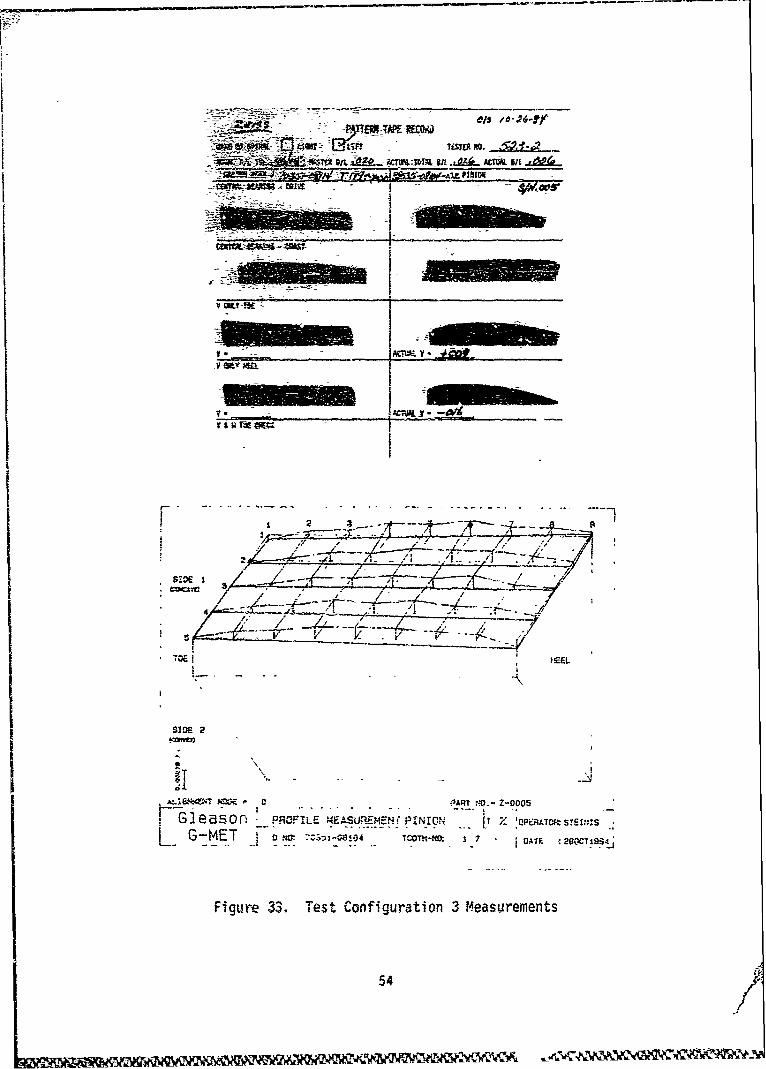
S! Tim No.sit ;&S -- - . .. .. A,' sit ÷ • _,
F ...............- ~ ... 1IL A.....ACIA..........."
isi
v OLT
. --
/ .- _ .. - -- ,
* •."---- '.-• ... /:--- ..... ~ --/-
S*. - /L • • . _ - - --,_ .. _•
, TOE I HEEL-. .
IT
- C ~PAt -V.- Z-0005
Gl1e aSO 0 PROFILE MEASU.REMEN( PINION i t Z PATaSEflG-MET M. .1 .,-O4 . 20OCT054:
Figure 33. Test Configuration 3 Measurements
54/
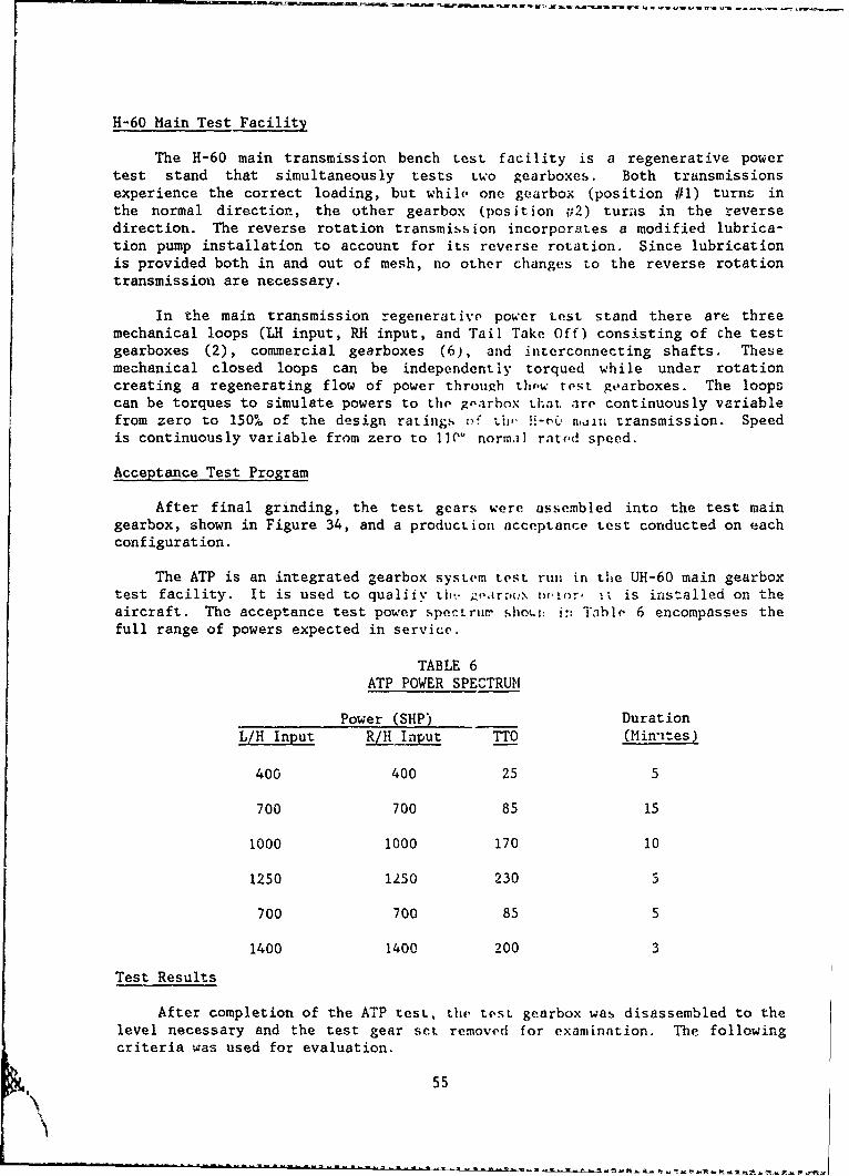
H-60 Main Test Facility
The H-60 main transmission bench test facility is a regenerative powertest stand that simultaneously tests two gearboxes. Both transmissionsexperience the correct loading, but while one gearbox (position #1) turns inthe normal direction, the other gearbox (position ,2) turns in the reversedirection. The reverse rotation transmission incorporates a modified lubrica-tion pump installation to account for its reverse rotation. Since lubricationis provided both in and out of mesh, no other changes to the reverse rotationtransmission are necessary.
In the main transmission regenerative power test stand there are threemechanical loops (LH input, RH input, and Tail Take Off) consisting of Che testgearboxes (2), commercial gearboxes (6), and interconnecting shafts. Thesemechanical closed loops can be independently torqued while under rotationcreating a regenerating flow of power through thew test gearboxes. The loopscan be torques to simulate powers to the gearbox that. are continuously variablefrom zero to 150% of the design ratings of tiiv H-tC' mIu transmission. Speedis continuously variable from zero to lIN' normal rati.d speed.
Acceptance Test Program
After final grinding, the test gears were assembled into the test maingearbox, shown in Figure 34, and a production acceptance test conducted on eachconfiguration.
The ATP is an integrated gearbox System test run in the UH-60 main gearboxtest facility. It is used to qualify thýi gear.:Nox outor, it is installed on theaircraft. The acceptance test power spectrumr sho..i: in= Table 6 encompasses thefull range of powers expected in service.
TABLE 6
ATP POWER SPECTRUM
Power (SHP) DurationL/H Input RJH Input TTO (Mnintes)
400 400 25 5
700 700 85 15
1000 1000 170 10
1250 1250 230 5
700 700 85 5
1400 1400 200 3
Test Results
After completion of the ATP test, the test gearbox was disassembled to thelevel necessary and the test gear set removed for examination. The followingcriteria was used for evaluation.
55
N'
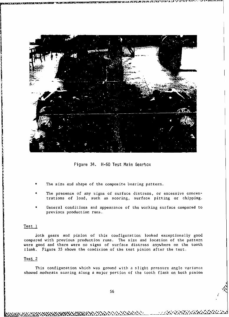
Figure 34. H-60 Test Main Gearbox
The size and shape of the composite bearing pattern.
• The presence of any signs of surface distress, or excessive concen-trations of load, such as scoring, surface pitting or chipping.
General conditions and appearance of the working surface compared toprevious production runs.
Test I
3oth gears and pinion of this configuration looked exceptionally goodcompared with previous production runs. The size and location of the patternwere good and there were no signs of surface distress anywhere on the toothtlank. Figure 35 shows the condition of the test pinion after the test.
Test 2
This configuration which was ground with a slight pressure angle varianceshowed moderate scoring along a major portion of the tooth flank on both pinion
56
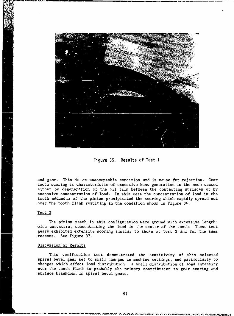
V
Figure 35. Results of Test 1
and gear. This is an unacceptable condition and is cause for rejection. Geartooth scoring is characteristic of excessive heat generation in the mesh causedeither by degeneration of the oil film between the contacting surfaces or byexcessive concentration of load. In this case the concentration of load in thetooth addendum of the pinion precipitated the scoring which rapidly spread outover the tooth flank resulting in the condition shown in Figure 36.
Test 3
The pinion teeth in this configuration were ground with excessive length-wise curvature, concentrating the load in the center of the tooth. These testgears exhibited extensive scoring similar to those of Test 2 and for the samereasons. See Figure 37.
Discussion of Results
This verificazion test demonstrated the sensitivity of this selectedspiral bevel gear set to small changes in machine settings, and particularly tochanges which affect load distribution, a small distribution of load intensityover the tooth flank is probably the primary contribution to gear scoring andsurface breakdown in spiral bevel gears.
57
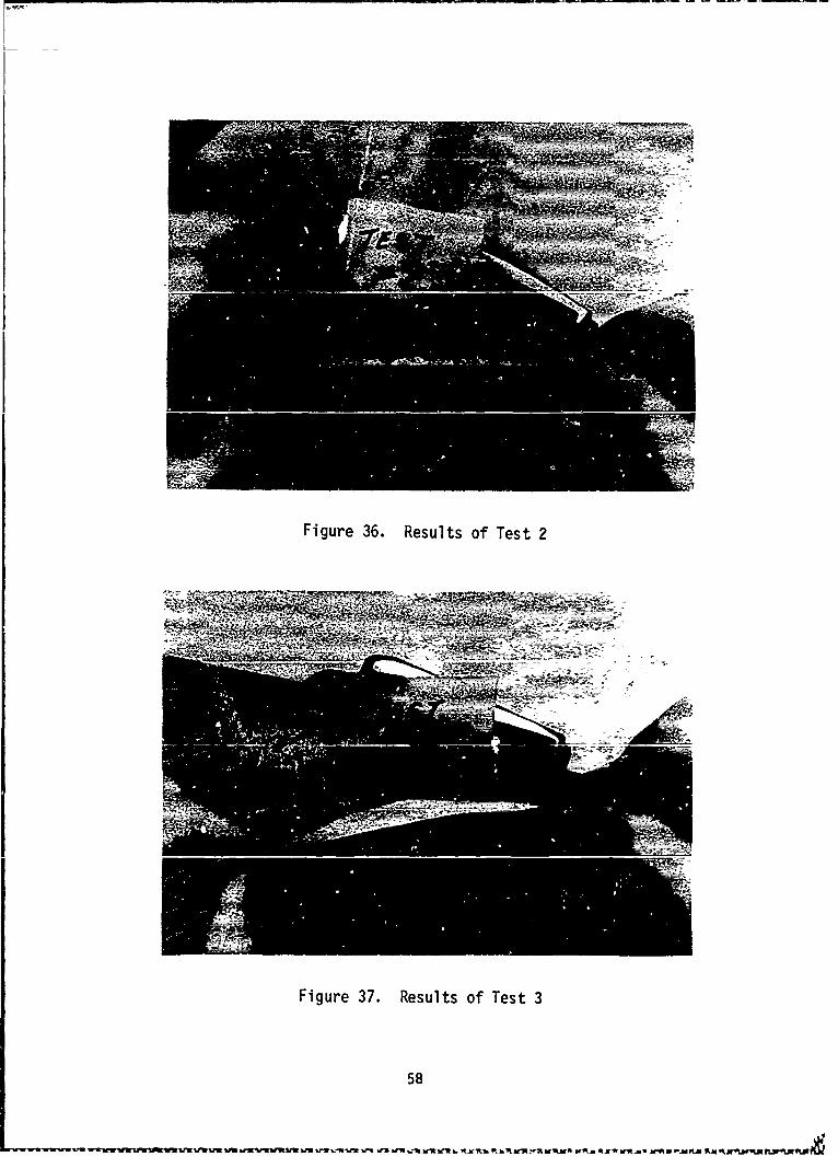
Figure 36. Results of Test 2
Figure 37. Results of Test 3
58
. I
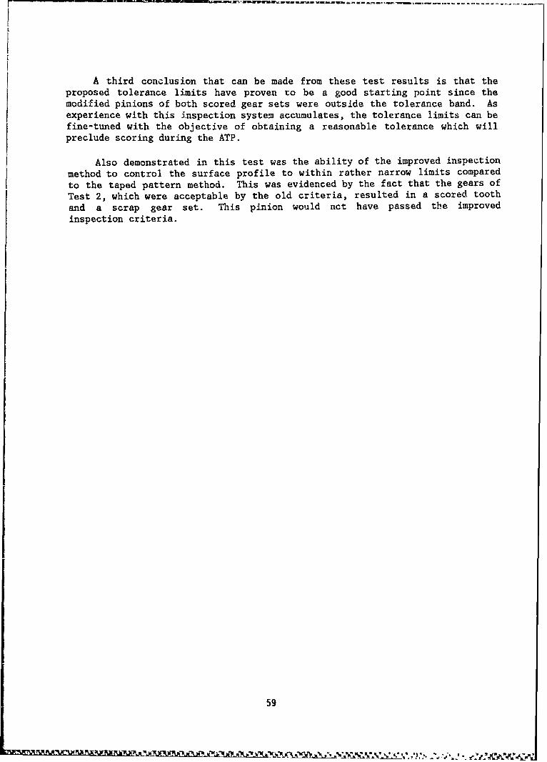
A third conclusion that can be made from these test results is that theproposed tolerance limits have proven to be a good starting point since themodified pinions of both scored gear sets were outside the tolerance band. Asexperience with this inspection system accumulates, the tolerance limits can befine-tuned with the objective of obtaining a reasonable tolerance which willpreclude scoring during the ATP.
Also demonstrated in this test was the ability of the improved inspectionmethod to control the surface profile to within rather narrow limits comparedto the taped pattern method. This was evidenced by the fact that the gears ofTest 2, which were acceptable by the old criteria, resulted in a scored toothand a scrap gear set. This pinion would not have passed the improvedinspection criteria.
59
ECONOMIC COST ANALYSIS
The projected savings in inspection and manufacturing times realized fromthe installation of the improved measurement process described herein wasestimated to be 7 3/4 hours per gear. The following dnalysis shows the equiva-lent dollar savings and resulting cash flow over a five-year period.
Basis for E'onomic Analysis
The data upon which the economic impact of the improved bevel gearoection process is based is shown in Table 7. It assumes that 50 percent of
tht: BLACK HAWK spiral bevel gears are produced at Sikorsky Aircraft, andestimates the benefits derived solely from that production over a five-yearperiod.
Income/Expense Statement
Table 8 lists the annual dollar savings and costs associated with the newinspection method in each of the five years. Table 9 presents the annual andcumulative cash flow situation and shows the payback pezcentages.
Results
Based upon the cash flow picture presented in Table 9, the calculatedbreakeven point for this investment is 1.56 years. The calculated presentworth, with an assumed acceptable rate of return of 23 percent, is $32C,700.The internal rate of return for zero present worth is 16.7, 39.1, 49.7, and55.2 respectively for years 2, 3, 4, and 5.
60
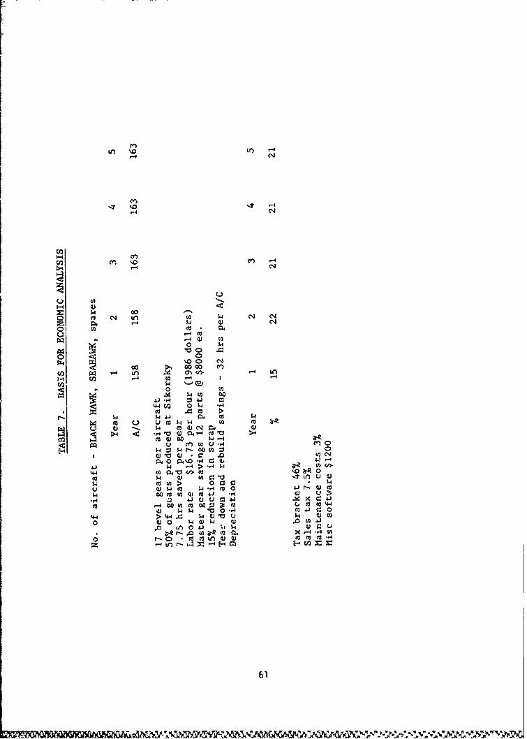
trl 'C Lr -
'-4 Ne
I--4
1-4 -N
00
00
o4 t 0w .qmz 4C m
0 4 14 4. 4 m
$.4 '0 0)0- M '0
(13 (U ~ 000 ý -
0i~4 0 4%0 -H4-0 E
o (4 ~ Ur-4 C',R
$O54 ItO 4Ln u 4En 2> 0 0
w $ --4 mJ 0 4JU r-
mO -4 00 0co 00 :33: L 0 caC044.1J 5.4 4 'o0 *f4 r
4-4 >'+ 44 0JV u- Q Vo 4)0 5.4)5 UJ4
o r-o. *COO*% 0 a 0(v('M
z tn ý4r -E 11E-W
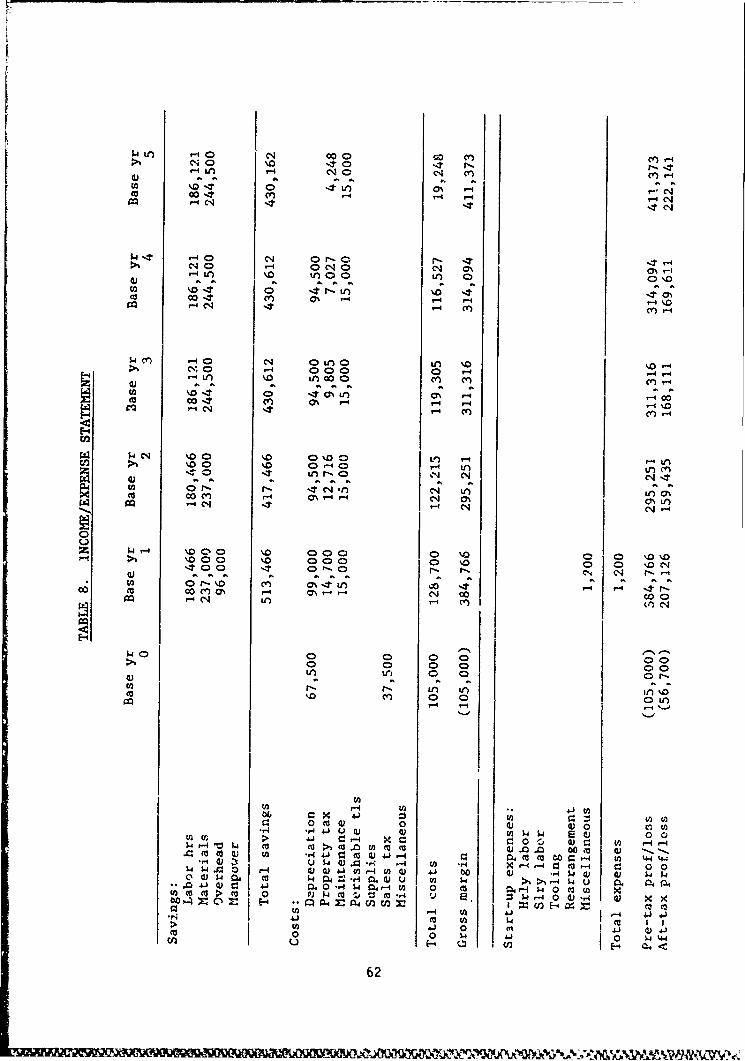
$4C 40a 1 000 co.4Cf r-.-4>1 0- NO NI a T "r-I
4) Il ai al a ý cl *. ar a\- T0 .4t ON '-" '-, N00 -T4 (I 44 vI CNr-4 C- -It ItN
1.4. '-0 N1 orr-4- -N% 040 -4 a N C1 0 % 3%-
41 '0. 0C4-t O .4.0
0 0 O I.4 Cf) 0% r- f4
'4C-4 4 r"' C'') cer-4
,-40 N* 0 LO0 if' \. 0'-N C000 0 a -4Ln U') 0 C?') cf) f
to. C'T ON '-4 C 00to00-:N CV) r4 C\
r- -4c ) r
N 0 0 00 \a0 0 Lco\00 0' "s-40 7-4 U')n
z .4 -4 \D0 \.O 000 0 %0 a' \0 \D'00 %0 000 0C 0 0 N
PU'4 C- n-4 CY)I (n)C14
04 C) 0001 0 0 0 0 0
If) 0 -0n O-0\0 C"a) 0 0
U) ,-r-U
00m4) 00
0 041 0 O0 C:O. OO : :00 4 : tco ca >1 'n w m (a Q .0 0~O 010 Q)
L4$i0 = 0 - 4) Q) " 0-4 U)0) 4J 00 (v (v1. 4)(4)QW4 0 w 0 C.4 040 4 4 , ( 0 m 4- 4 0 MED
U 0 > w 0 w m .40 = m r.4 V'E.J $4 -~4 04 4 4) w x xYI ~ - 4/2 E - 4 41
IC' ~0 4't W,0 0 0 S.4 4.) 0 w.4
62
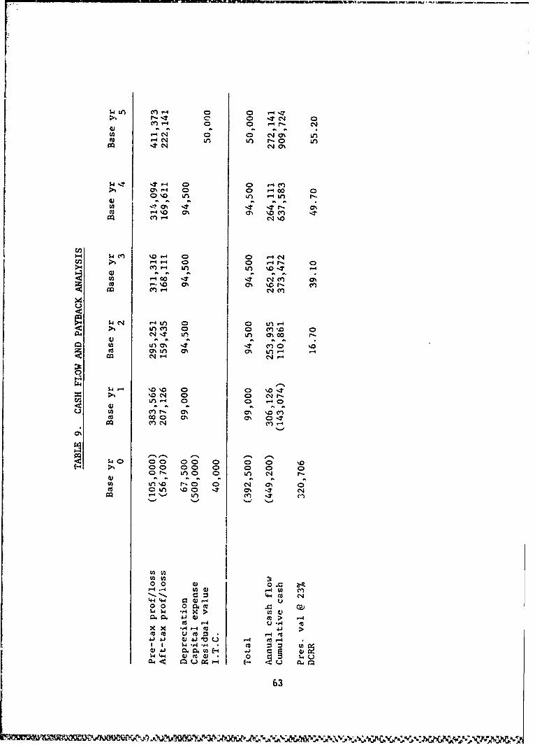
w.u CL*p. 0n 0 ,44r'- -I C, 0 .4C'J4 0
cn -4 0 0 r-4 fW aý al a7 C7 0 a
w -t r-4u 0 40 1l-4 lafc 0- 0 V00 0
0~cx 10 .4cL0
m "4 % CA m' %D c9Q M -4 1N %1
w 4-' %0'. 0 0 '04N
cc. 0c 0N 0N c'Jr- (fn ~ 0f 0- N-0
>1 Uc)0 0' 0' .0.
1.4 00 00 0 T 0 0 'go4 00 004 0 0 0
%0- C14 O 0 if 4 eJ
ay a- a% a% %. a M
CO 0 Z0 C) -0 0 a 0 0'0 0u a00 04 0' .
mq.. C~ .4 C) -lC
to to4 1- 30 0 (U 0r. Bp- .3 f- W (00 0J 0..0vUC?-4
41~ Q)'0 m- > -4co~4 GJ 4J u .0
W~ 4 t.04- 0-
63
CONCLUSIUNS
1. An improved inspection method for spiral bevel gears was defined anddemonstrated for both in-process and final inspection,
2. The method permits quantitative evaluation of bevel gear tooth profilesand eliminates the subjective accept/reject decision making which ischaracteristic of the present contact pattern method.
3. The defined process automatically calculates grinding machine settingchanges necessary to correct an out-of-tolerance profile, in two grindingcycles.
4. Manufacturing and inspection time for spiral bevel gears is reduced by 73/4 hours per gear resulting in significant cost savings.
5. The entire tooth contact surface can De measured and controlled ratherthan a localized contact area.
6. The measuring machine has the capability of measuring blank dimensions aswell as tooth index and spacing errors.
7. The process produces permanent digital and graphical inspection recordsfor each gear measured.
8. The need for maintenance and inspection of primary and sub-ties hardmaster gears is eliminated.
9. The coordinate measurement machine replaces three single-purpose gearmeasurement machines and has add:ticnl. un:vers3I capability which can beexploitei in areas other than gear ze e..
10. The improved inspection system utilizing tne muiti-axib coordinate measur-ing machine will produce higher-quality gears with fewer anomalies inacceptance test results.
64 ~v
APPENDIX IPROCESS SPEC I F I CATI ON
AUTOMATED INSPECTION AND PRECISION GERINDINGOF SPIRAL BEVEL GEARS
f. SCOPEi
1.1 Sccpe. This specification prescribes a manufacturing and inspectionprocess for spiral bevel gear tooth profile geometry using a diulti-axis Co-
ordinate measuring machine. it also describe thi. measuremcnt technique usingthe Zeiss model UMM 500 and deflneb the quality requirements and inspectiontolerances to be used in Lbe interpretation of the measuorement data.
1.2 Classification. The procedures and tciuri'nces prescribed hereinshall apply to aircraft-quality primary-drive spiral bevel gears, ronformingapproximately tu AGMA classes 11, 12. and 1,.
2. APPLICABLE DOCUMENTS
2.1 Referenced Documents. rhe folloniing documents of the issue in effecton the data of invitation for bids or request for proposal, form a part of thisspecification to the extent specified herein.
ZEISS DOCUMENTATION
COMET TI, Coordinate Metrology Software.Operating Instructions.
GLEASON DOCUMENTATION
G-AGE Users ManualHypoid Generator Operating ii-:r:.t c:Hypoid Grinder Operating InstructionsApplication Engineering On-Line Gomputer
Service Instructions
3. REQUIREMENTS
3.1 Equipment. The following 2quipment is required for the meisurementprocess described below.
ZEISS UNIVERSAL MEASURING MACHINE UM. 500
Basic machine, including CNC, Antivibration sy:stem, Interface,Calibration sphere, starprobe. Probe kit, and Peripheal station.
Optical equipment with Probe kit for gear measurement.
Rotary table, RT05, with Interface/and Expander
Hewlett Packard Desktop Computer Systen including HP 9836 calculator,HP 9862A X-Y plotter and impact line printer
65
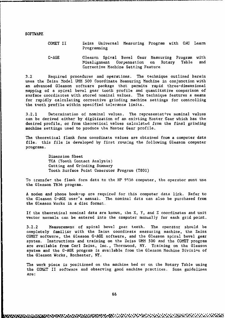
SOFTWARE
COMET II Zeiss Universal Measuring Program with CAC LearnProgramming
G-AGE Gleason Spiral Bevel Gear Measuring Program withMisalignment Coirpensation on Rotary Table andCorrective Machine Setting Feature
3.2 Required procedures and operations. The technique outlined hereinuses the Zeiss Model IRV. 500 Coordinate Measuring Machine in conjunction withan advanced Gleason softiVare package that permits rapid three'-dimensionalmapping of a spiral bevel gear tooth profile and quantitative comparison ofsurface coordinates with stored nominal values. The technique features a meansfor rapidly calculating corrective grinding machine settings for controllingthe tooth profile within specified tolerance limits.
3.2.1 DeterminatioD of nominal values. The representat 4 ve nominal valuescan be derived either by digitization of an existing Master Gear which has thedesired profile, or from theoretical values calculated from the final grindingmachine settings used to produce the Master Gear profile.
The theoretical flank form coordinate values are obtained from a computer datafile. this file is developed by first running the following Gleason computerprograms.
Dimension SheetTCA (Tooth Contact Analysis)Cutting and Grinding SummaryTooth Surface Point Cenerator Program (T801)
To transfer the flank form data to the HP 9336 computer, the operator must usethe Gleason T836 program.
A modem and phone hook-up are required for this computer data link. Refer tcthe Gleason G-AGE user's manual. The nominal data can also be purchased fromthe Gleason Works in a disc format.
If the theoretical nominal data are known, the X, Y, and Z coordinates and unitvector normals can be entered into the computer manually for each grid point.
3.2.2 Measurement of spiral bevel gear teeth. The operator should becompletely familiar with the Zeiss coordinate measuring machine, the ZeissCOMET software, the Gleason G-AGE software, and the Gleason spiral bevel gearsystem. Instructions and training on the Zeiss UMM 500 and the COMET programare available from Carl Zeiss, Inc., Thornwood, NY. Training on the Gleasonsystem and the G-AGE program is available from the Gleason Machine Divisinn ofthe Gleason Works, Rochester, NY.
The work piece is positioned on the machine bed or on the Rotary Table usingthe COMiT II software and observing good machine practices. Some guidelinesare:
66
J~ley

Use the same tooling points as used on the Gleason grinder and/ox
generator
Do not use proof diameters because they mnay not be. accurats
The gear axis should be in the vertical plane (Z axis).
If stored theoretical data is not available or applicable, the: required nomiinalvalues can be taken from an existing Master Gear. First the corner points ofI the surface grid are probed manuaily or they can be ca~culated, for a givenedge distance, using the formulas in Table 1. After the grid density ischosen, the measurement process proceeds automatica.1ly.
For the case where the nominal values have already been generated and stored inthe co>mputer, and a production gear positioned on the machine; the measurementprocess is automatic. After initial cont-azt hias been mnade, the. probe isdirected by the computer to each grid point, measures the coordinate5, andcompares the surface normal at that loc~tion to its nowinal value. When eachtooth is measured: the probe automatically travelIs to the next designatedtooth.
The measurement data is presented both as a three-~dimensional error plot and asa digital table of deviations from nomiinal values,
3.a.3 Cowparison with nominal values. The correctiveý feature. of theGleason G-AGE computer program will only correct first orde~r changes.. Theprogram will print out the delta grinding machine settings required to correct
the profile. The prograin does no- always correct the deli-nquent machinesetting and in certain cases the recommended setting changes can affect otherareas of the tooth. For example:
A pini-on ground with a aci-enrtobkerror- will be directedto use the ecceptric artgle anti pressure ang-le. to correct the firstorder variance.
A gea grolund with a machine-center-to-back error will use theeccentric angle and the Xroot angle. to correc-t the variance.
In the case of the &ear ths root angle c-hange c-an be ietrimental t;.o stockremoval in the root of the tocthk. lik both cases i%. may require a seco.nid Orderlengthwise, curvature change to correct the total flank forn..
a"1
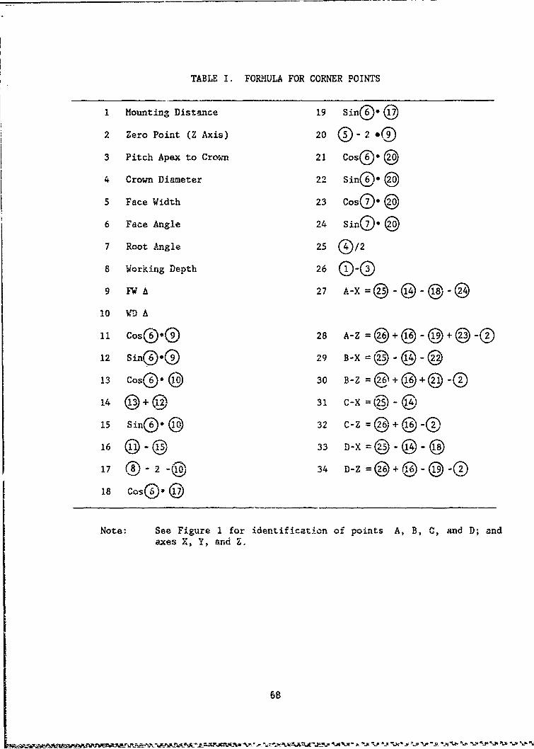
TABLE I. FORMULA FOR CORNER POINTS
1 Mounting Distance 19 Sin®' ©2 Zero Point (Z Axis) 20 "-2 "0
3 Pitch Apex to Crov.wn 21 Cosoe @
4 Crown Diameter 22 Sin®. ®5 Face Width 23 Cos@o 03
6 Face Angle 24 Sino'@
7 Root Angle 25 0/2
8 Working Depth 26 0-09 27 A-xN 27
10 - A
11 Cos@.® 28 @- @-@
12 Sin®@ 029 Bz = 205
13 Cos~ ®Z 30 B-Z = +(D6-14 @+@(-, 31 -X--C-415 Sin- 32 C-x@ -@ -
16 @®-®'10 33 D-X=02-@ -@
17 -2-00 34 D -Z@ + @- @ -02
18 Coso. @
Note: See Figure I for identification of points A, B, C, and D; andaxes X, Y, and Z.
68

[c
z
y - .• -
0 ,000. " . -
%m
Figure 1. Definition of Axes and Corner Points
69

3.3 Recoummended procedures and operations. The three-dimensional plot ofthe variances from nominal values, in some cases, will suggest first order andlimited second order changes which can be made without the benefit of the G-AGEcorrection program.
3.3.1 Pressure angle variance (First Orr• The pressure angle variancecan be determined by evaluating the measured data grid points at 5-1, 5-3 and5-5 (Ref. Figure 2) of a 9 x 5 measured grid. If the total variation were.0005 over a measured depth of .4 the correction to the machine pressure anglewould be 0.07160 (00 04.2'). This delta correction can be calculated using thefollowing formula.
PA = TAN 1I Ecc Rd
PAc = Pressure angle changeEc = Effective changeld Measuring depth (see NoteA)
NOTE A: The measured depth can be derived from the Gleason computer programTheory/T801 if the measuring data is using theoretical data or can bederived from the program used to calculate the height and radius forthe four corner points.
The direction of the pressure angle change can be determined by referring tothe Gleason Hypoid Grinder Operating Instruction manual.
3.3.2 Spiral angle variance (First Orler). The spiral angle variance canbe determined by evaluating the measure 3ta at grid points 1-3, 5-3 and 9-3(Ref. Figure 2) of a 9 x 5 measured g;_A. If the total variation were .001over a face width of 3 inches and a 250 spiral angle, the eccentric anglecorrection would be .018540 (00 01.1'). The delta correction can be calculatedusing the following formula.
E/A- TAN 1 Ecc FW - (FWA 0 2) 1
Cos S/A
E/Ac = Eccentric angle changeFW = Face widthFW A = Face width delta (see Note B)S/A = Spiral angleEc = Effective change
NOTF B: The face width delta is deriveo from the Gleason computer program,Theory/T801 if the measuring data is z-sing theoretical d&ta or can bederived from the pr.6ram used to calculate the height and radius forthe four corner points.
The direction of the eccentric angle change can be determined by referring tothe Gleason Hypoid Grinder Operating Instruction manual.
70
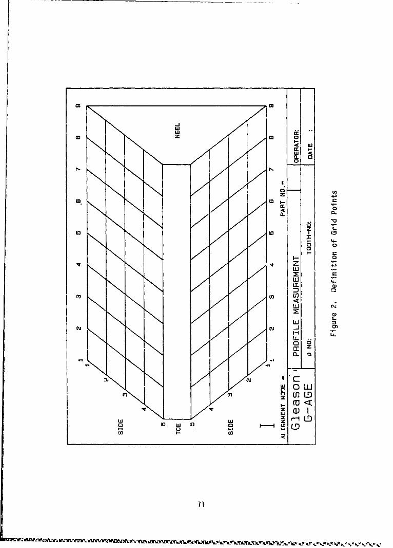
LL
co 03
I--.4 IU
CLU
C CL
z ~4.
4 0-0. a-
D1
Zn S.
I-q
Lii
V41414
u~i 0 LL
wZ a
w z
6-4
cT I
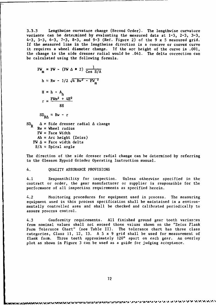
3.3.3 Lengthwise curvature change (Second Order). The lengthwise curvaturevariance can be deteimined by evaluating the measured data at 1-3, 2-3, 3-3,4-3, 5-3, 6-3, 7-3, 8-3, and 9-3 (Ref. Figure 2) of the 9 x 5 measured grid.If the measured line in the lengthwise direction is a concave or convex curveit requires a wheel diameter change. If the arc height of the curve is .001,the change to the side dresser radial would be .041. The delta correction canbe calculated using the following formula.
1
FWm = FW - (FW A 0 2) Cos S/A
h = Rw - 1/2 44 Rw4 - FW -m
H h - Ah
FW1M2 + 4H2r-
8H
SDRA = Rw - r
SDR A = Side dresser radial A changeRw = Wheel radius
FW = Face WidthAh = Arc height (Zeiss)
FW A = Face width deltaS/A = Spiral angle
The direction of the side dresser radial change can be determined by referringto the Gleason Hypoid Grinder Operating Instruction manual.
4. QUALITY ASSURANCE PROVISIONS
4.1 Responsibility for inspection. Unless otherwise specified in thecontract or order, the gear manufacturer or supplier is responsible for theperformance of all inspection requirements as specified herein.
4.2 Monitoring procedures for equipment used in process. The measuringequipment used in this process specification shall be maintained in a environ-mentally controlled area and shall be checked and calibrated periodically toassure process control.
4.3 Conformity requirements. All finished ground gear tooth variances
from nominal values shall not exceed those values shown on the "Zeiss FlankForm Tolerance Chart" (see Table II). The tolerance chart has three classcategories, Class 11, 12, 13. A 5 x 9 grid shall be used for measurement of
flank form. Three teeth approximately 1200 apart on each gear. An over]ayplot as shown in Figure 3 can be used as a guide for judging acceptance.
72
•_. e?.m1r• %•.1RA • V k1
Ut•VX'JJ .Xt'%J X .A .. P " . • ' ,% ' " ,A V' X.AN . V 2-.
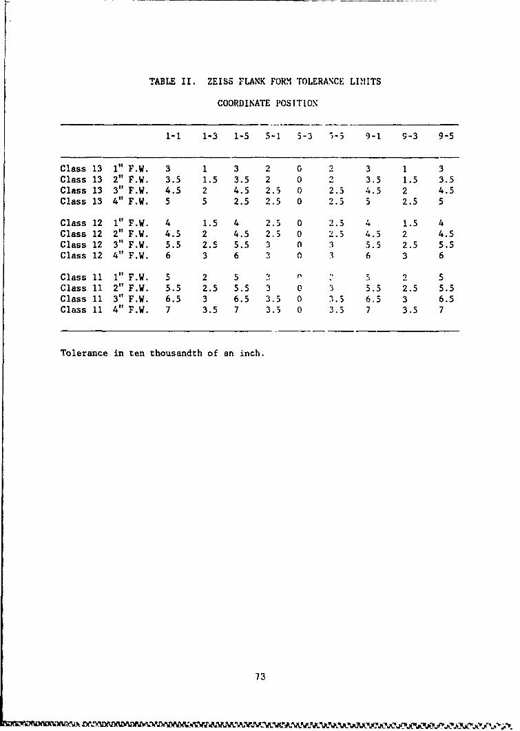
TABLE II. ZEISS FLANK FORM TOLERANCE LIMITS
COORDINATE POSITION
1-1 1-3 1-5 5-1 5-3 1-5 9-1 9-3 9-5
Class 13 1" F.W. 3 1 3 2 0 2 3 1 3Class 13 2" F.W. 3.5 1.5 3.5 2 0 2 3.5 1.5 3.5Class 13 3" F.W. 4.5 2 4.5 2.5 0 2.5 4.5 2 4.5Class 13 4" F.W. 5 5 2.5 2.5 0 2.5 5 2.5 5
Class 12 1" F.W. 4 1.5 4 2.5 0 2.5 4 1.5 4Class 12 2" F.W. 4.5 2 4.5 2.5 0 2.5 4.5 2 4.5Class 12 3" F.W. 5.5 2.5 5.5 3 0 3 5.5 2.5 5.5Class 12 4" F.W. 6 3 6 3 0 3 6 3 6
Class 11 1" F.W. 5 2 5 P :, 5 2 5Class 11 2" F.W. 5.5 2.5 5.5 3 0 3 5.5 2.5 5.5Class 11 3" F.W. 6.5 3 6.5 3.5 0 3.5 6.5 3 6.5Class 11 4" F.W. 7 3.5 7 3.3 0 3.5 7 3.5 7
Tolerance in ten thousandth of an inch.
73
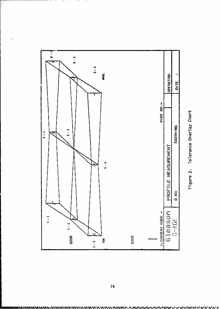
UI-a: 0
W 44
- S.
z cz
cno 0nt
74,
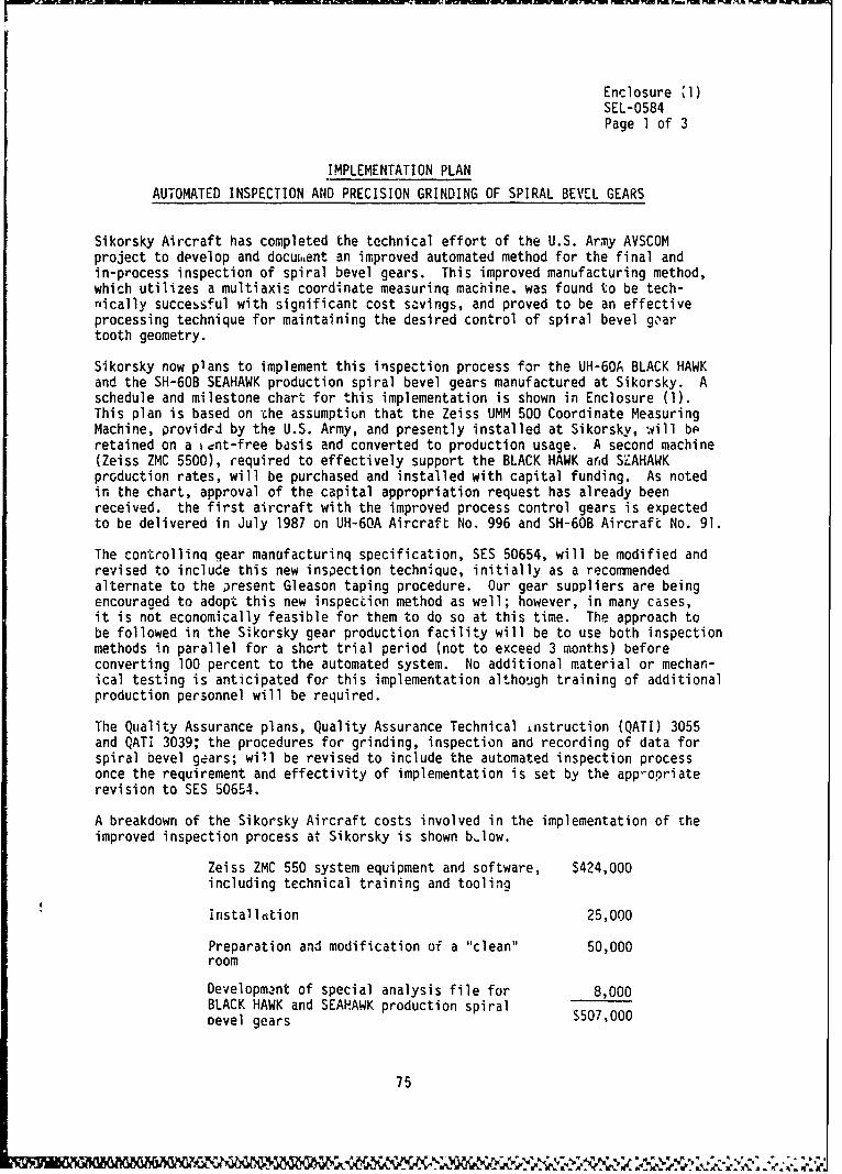
Enclosure %l)SEL-0584Page I of 3
IMPLEMENTATION PLAN
AUTOMATED INSPECTION AND PRECISION GRINDING OF SPIRAL BEVEL GEARS
Sikorsky Aircraft has completed the technical effort of the U.S. Army AVSCOMproject to develop and docui,,ent an improved automated method for the final andin-process inspection of spiral bevel gears. This improved manufacturing method,which utilizes a multiaxis coordinate measurinq machine, was found to be tech-nically successful with significant cost savings, and proved to be an effectiveprocessing technique for maintaining the desired control of spiral bevel geartooth geometry.
Sikorsky now plans to implement this inspection process for the UH-60A BLACK HAWKand the SH-60B SEAHAWK production spiral bevel gears manufactured at Sikorsky. Aschedule and milestone chart for this implementation is shown in Enclosure (1).This plan is based on the assumptiun that the Zeiss UMM 500 Coordinate MeasuringMachine, providrd by the U.S. Army, and presently installed at Sikorsky, will beretained on a iant-free bdsis and converted to production usage. A second machine(Zeiss ZMC 5500), required to effectively support the BLACK HAWK and SEAHAWKproduction rates, will be purchased and installed with capital funding. As notedin the chart, approval of the capital appropriation request has already beenreceived, the first aircraft with the improved process control gears is expectedto be delivered in July 1987 on UH-60A Aircraft No. 996 and SH-60B Aircraft No. 91.
The controllinq gear manufacturinq specification, SES 50654, will be modified andrevised to include this new inspection technique, initially as a recommendedalternate to the present Gleason taping procedure. Our gear suppliers are beingencouraged to adopt this new inspection method as well; however, in many cases,it is not economically feasible for them to do so at this time. The approach tobe followed in the Sikorsky gear production facility will be to use both inspectionmethods in parallel for a short trial period (not to exceed 3 months) beforeconverting 100 percent to the automated system. No additional material or mechan-ical testing is anticipated for this implementation although training of additionalproduction personnel will be required.
The Quality Assurance plans, Quality Assurance Technical instruction (QATI) 3055and QATI 3039; the procedures for grinding, inspection and recording of data forspiral bevel gears; will be revised to include the automated inspection processonce the requirement and effectivity of implementation is set by the app-opriaterevision to SES 50654.
A breakdown of the Sikorsky Aircraft costs involved in the implementation of theimproved inspection process at Sikorsky is shown blow.
Zeiss ZMC 550 system equipment and software, $424,000including technical training and tooling
installation 25,000
Preparation and modification of a "clean" 50,000room
Development of special analysis file for 8,000BLACK HAWK and SEAHAWK production spiraloevel gears S507,000
75

Enclosure (1)SEL-0584Page 2 of 3
The implementation of this improved manufacturing process will improve thequality of spiral bevel gears produced at Sikorsky with fewer rejection ratestraiceable to nonconforming tooth profiles. This effect is achieved with signifi-cant manufacturing cost savings arid will result in longer life gears requiringfewer spares.
76
~~~~~kA a, ýk ' . ~ ~ ft.j~..u-
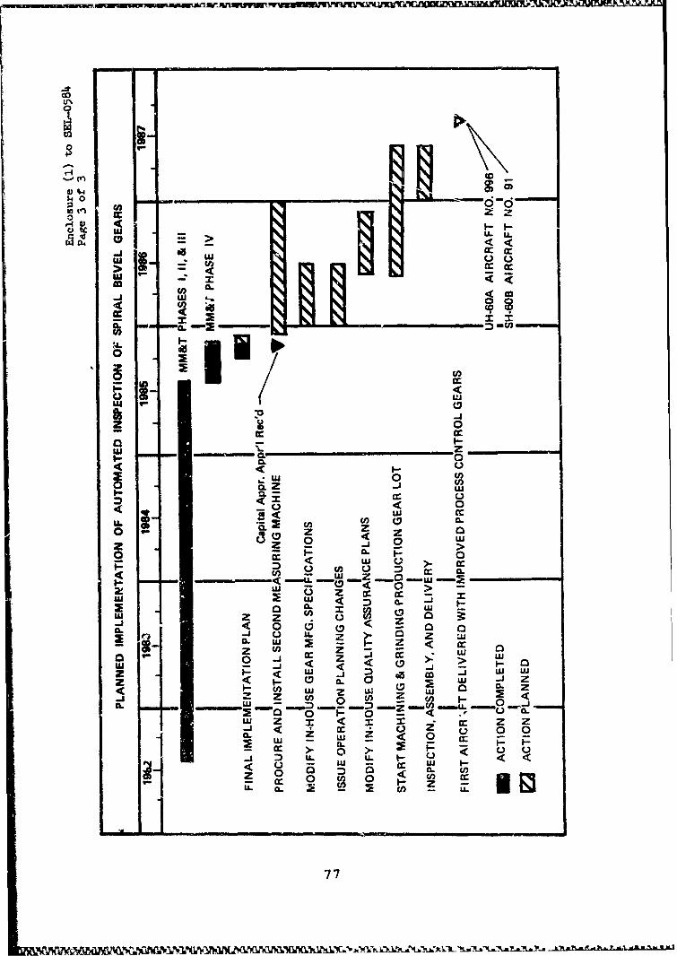
U%0
00
NM
r-4-4w) tic U.A
t (
LU
83 PU -i
00
2 0a I-I
w I- z ____0. 00
0- -___-
< w twu wwj
C U Z cc
wz z C.! ai 3< 0 0 (D a a
SC.) LA. zz MCL w 2 - z c.u1 - U) cc Z IC) -z z4 >~ 0
< <9
-j w -jA. L
CU 0 U) <~
CL m Umi
77L
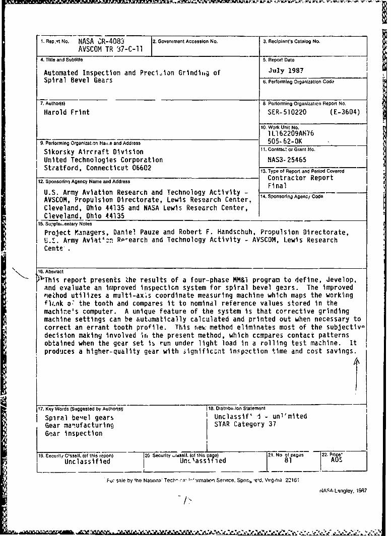
1. Rep.,r No. NASA CR-408 2. Government Accession No. 3. Recipiant's Catalog No.
AVSCOM TR 37-C-11 I4. Title and Subtitle 5. Report Dato
Automated Inspection and Precision Grinditg of July 1987Spiral Bevel Gears 6. Performing Organization Coda
7. Author(s) 8 Performing Organizaticn Report No.
Harold Frint SER-510220 (E-3604)
10, Work Unit No.
1 L162209AH769. Performing Organlzat.on Vao.e and Address 505- 62-OK
Sikorsky Aircraft Division 11. contral.! or Grant No.
United Technologies Corporation NAS3-25465Stratford, Connecticut 06602 13. Type of Report and Period Covere_7_d
12. Sponsorlnq Agency Name and Address Contractor ReportFinal
U.S. Army Aviation Research and Technology Activity - Sponsoring AgncCd
AVSCOM, Propulsion Directorate, Lewis Research Center, 14.SponsorinAgencf Code
Cleveland, Ohio 44135 and NASA Lewis Research Center,Cleveland, Ohio 44135
"15. Supple,.,entary Notes
Project Managers, Daniel Pauze and Robert F. Handschuh, Propulsion Directorate,U.Z. Army Aviat'"n RP-earch and Technology Activity - AVSCOM, Lewis ResearchCente.
16. Abstract
" L6 This report presents the results of a four-phase MM&l program to define, develop.and evaluate an irmproved inspection system for spiral bevel ge.,rs. The improvedrieLhod utilizes a multi-ax's coordinate measuring machine which maps the working
l;,.nk o7 the tooth and compares it to nomindl reference values stored in themachire's computer. A unique feature of the system is that corrective grindingmachine settings can be automatically calculated and printed out when necessary tocorrect an errant tooth profile. This new method eliminates most of the subjectivedecision makiny involved it, the present method, which ccmpares contact patternsobtained when the gear set is run under light load in a rolling test machine. Itproduces a higher-quality gear with signific.;nt In.pection time and cost savings.
417. Key Words (Suggested by Autho-1s)) 18. Distrnbuion Statement
Spiral bewel gears Unclassif' J - unl'mitedGear man.ufacturing STAR Category 37Gear inspection
19. Eecurit, Clssslf. (of this repon) 126 Security ,,itsslf. (of this paNo pages 22. Price'
Unclassified I Un,)assi-Med 81 A05Fu: sale by 1he Nationa' Tectw ca' "-')rmatl•on Service. Sprný, ,e'd. Virg,nia 2216'
NA-IAA-Langley. 1987S-- >