Embed Size (px)
Citation preview
Inspection and Repair of Concrete Road Structures
AM-STR-06005
June 2014
Asset Management &
Maintenance
Standards
AM
TRANSPORT INFRASTRUCTURE IRELAND (TII) PUBLICATIONS
About TII Transport Infrastructure Ireland (TII) is responsible for managing and improving the country’s national road and light rail networks. About TII Publications TII maintains an online suite of technical publications, which is managed through the TII Publications website. The contents of TII Publications is clearly split into ‘Standards’ and ‘Technical’ documentation. All documentation for implementation on TII schemes is collectively referred to as TII Publications (Standards), and all other documentation within the system is collectively referred to as TII Publications (Technical). This system replaces the NRA Design Manual for Roads and Bridges (NRA DMRB) and the NRA Manual of Contract Documents for Road Works (NRA MCDRW). Document Attributes Each document within TII Publications has a range of attributes associated with it, which allows for efficient access and retrieval of the document from the website. These attributes are also contained on the inside cover of each current document, for reference. For migration of documents from the NRA and RPA to the new system, each current document was assigned with new outer front and rear covers. Apart from the covers, and inside cover pages, the documents contain the same information as previously within the NRA or RPA systems, including historical references such as those contained within NRA DMRB and NRA MCDRW. Document Attributes
TII Publication Title Inspection and Repair of Concrete Road Structures TII Publication Number
AM-STR-06005
Activity Asset Management &
Maintenance (AM)
Document Set
Standards
Stream Structures (STR) Publication Date June 2014
Document Number
06005 Historical Reference
NRA BA 35
NRA DMRB and MCDRW References For all documents that existed within the NRA DMRB or the NRA MCDRW prior to the launch of TII Publications, the NRA document reference used previously is listed above under ‘historical reference’. The TII Publication Number also shown above now supersedes this historical reference. All historical references within this document are deemed to be replaced by the TII Publication Number. For the equivalent TII Publication Number for all other historical references contained within this document, please refer to the TII Publications website.
Volume 3 Section 3
Part 3
NRA BA 35/14
Inspection and Repair of
Concrete Road Structures
June 2014
St. Martin’s House, Waterloo Road, Dublin 4. Tel:+353 1 660 2511 Fax +353 1 668 0009 Email : [email protected] Web : www.nra.ie

Summary:
This Advice Note is intended to assist the Engineer responsible for carrying out Principal Inspections,
Special Inspections and the repair of concrete road structures.
Published by National Roads Authority, Dublin 2014
DESIGN MANUAL FOR ROADS AND BRIDGES
June 2014 i
VOLUME 3 ROAD STRUCTURES:
INSPECTION AND MAINTENANCE
SECTION 3 REPAIR
PART 3
NRA BA 35/14
INSPECTION AND REPAIR OF
CONCRETE ROAD STRUCTURES
Contents
Chapter
1. Introduction
2. Scope
3. Defects in Concrete
4. Principal Inspections
5. Special Inspections
6. Testing
7. Repairs to Chloride Contaminated Structures
8. Surface Impregnation
9. Draining of Voids within Bridge Decks
10. Alkali – Silica Reaction
11. References
12. Enquiries
National Roads Authority Volume 3 Section 3
Design Manual for Roads and Bridges Part 3 BA 35/14
June 2014 1
1. INTRODUCTION
1.1 The National Roads Authority’s procedures for Principal Inspections are given in NRA BD 301.
The procedures for Routine Inspections & Maintenance are given in NRA BD 302. To enable
structures to retain their serviceability it is important that defects and causes of deterioration are
identified as soon as possible so that remedial works can be carried out.
1.2 The most serious cause of deterioration in the National Roads Authority's concrete road structures
is reinforcement corrosion due to the presence of free chloride ions in the concrete. These come
mainly from de-icing salt, although at coastal sites wind-borne chlorides and sea-water are
alternative sources. Alkali-silica reaction (ASR) is another known cause of deterioration but
deleterious damage due to ASR has not been widely reported in Ireland. In both cases a
substantial reduction in the service lives of affected structures may occur.

National Roads Authority Volume 3 Section 3
Design Manual for Roads and Bridges Part 3 BA 35/14
June 2014 2
2. SCOPE
2.1 This NRA Advice Note is intended to assist the Engineer responsible for carrying out Principal
Inspections, Special Inspections and the repair of concrete road structures.
National Roads Authority Volume 3 Section 3
Design Manual for Roads and Bridges Part 3 BA 35/14
June 2014 3
3. DEFECTS IN CONCRETE
General
3.1 The first indications of serious deterioration can usually be identified in Principal Inspections
(refer to NRA BD 301). The visual signs are cracks, spalls and rust stains. However local pitting
corrosion can develop with no obvious signs and additional internal stresses may be induced by
ASR. On bridge decks, failure of the carriageway surfacing may indicate problems with the deck
concrete. It is important to determine the causes of deterioration and their likely consequences
before deciding on the type and scale of remedial works.
Durability
3.2 Durability may be defined in general terms as the ability of a structure to retain its serviceability.
Durability is affected by original design faults, poor detailing, the use of unsuitable materials,
shortfalls in workmanship and lack of routine maintenance. These inadequacies accelerate
penetration of the concrete by atmospheric carbon dioxide and water borne chloride ions from de-
icing salts and marine environments.
3.3 Serious breakdown occurs where concrete is permeable or concrete cover to reinforcement is
deficient. Permeable concrete is caused by high water/cement ratios, low cement contents,
inadequate curing and poor compaction. Lack of an effective waterproof membrane, blocked
surface water drainage, leaking expansion joints or spray from passing traffic are all means by
which water reaches the surfaces of decks, piers and abutments. Concrete with a high alkali
content, reactive aggregates and sufficient moisture is also at risk from alkali-silica reaction (see
Section 10).
Surface Deterioration of Concrete
3.4 Frost damage and leaching are probably the most common causes of surface deterioration.
Frost Damage
3.4.1 This usually starts as scaling and may be followed by loosening of the surface aggregates
and is most prevalent on horizontal surfaces. Frost damage on vertical surfaces is often
associated with spalling and progressive cracking. Poor quality or poorly compacted
concretes and concretes containing shrinkable aggregates are readily saturated and
vulnerable. De-icing salts and urea exacerbate the problem as thermal shock is caused
when latent heat required to melt snow and ice is extracted from the concrete. The
resulting differential temperature induces secondary tensile stresses, which in combination
with stresses already in the concrete exceed the tensile strength and scaling occurs.
Leaching
3.4.2 Water migrating through permeable concrete reduces both its alkalinity and its strength as
it leaches lime from the concrete and deposits it on the surface. Evaporation of moisture
leaves unsightly deposits on the surface. Leaching is frequently associated with
construction joints although these are not essential for its occurrence.

National Roads Authority Volume 3 Section 3
Design Manual for Roads and Bridges Part 3 BA 35/14
June 2014 4
Cracks
3.4.3 Fine cracks may occur in tensile zones of reinforced concrete members under normal
design loading conditions because concrete can only sustain a relatively small tensile
stress before cracking develops. Design codes limit calculated crack widths according to
exposure condition. However cracks may also form for a variety of reasons e.g. structural
deficiency, settlement or ASR. Thermal and shrinkage cracks may be associated with high
cement contents. All cracking may affect the serviceability of a member. Where cracks
significantly increase the permeability of the concrete and the risk of reinforcement
corrosion they should be considered deleterious.
Corrosion of the Reinforcement
3.5 Corrosion can be classified into two types: general corrosion associated with carbonation and
pitting corrosion associated with chloride ions.
3.5.1 Carbonation is a chemical reaction between atmospheric carbon dioxide and hydrated
cement compounds which causes a reduction in the alkalinity of the concrete. The rate of
carbonation is dependent on the permeability and moisture content of the concrete. As the
pH of the concrete falls below 11.5 the protection afforded to the reinforcing steel is
reduced, and corrosion may occur. General corrosion is characterized by superficial
corrosion products being generated over relatively large areas of the reinforcement
causing cracking and spalling of the cover concrete. Usually there is initially a minimal
loss of section. Conditions for rapid carbonation are not entirely the same as conditions
for reinforcement corrosion but the depth of carbonation is of significance in assessing the
risk of corrosion. In modern well-constructed road structures the rate of carbonation is
low giving a long period of time before the steel is depassivated. Urea used as a de-icing
agent decomposes into carbon dioxide and ammonia. Its use may increase the risk of
carbonation.
3.5.2 Penetration of concrete by chloride ions from de-icing salts and marine environments is
the primary cause of reinforcement corrosion in road structures. The miniscule and highly
mobile free chloride ion is able to penetrate concrete through the water present in the pore
structure. The passive layer surrounding the reinforcement is locally broken down,
causing the anode of an electro-chemical cell to form and anodic pitting corrosion to
develop. The cathode may be an adjacent area of steel, or other layers of reinforcement.
Once corrosion is initiated the rate of corrosion is determined by the availability of
oxygen and moisture and the resistivity of the concrete, but pitting corrosion is rapid and
severe local loss of section can occur. Corrosion will be accelerated in damp concrete with
a high water/cement ratio and low electrical resistivity. The products of pitting corrosion
may initially be black with no external visual clues to their existence. Where sufficient
oxygen is available the black corrosion product turns to red rust which is expansive and
can lead to cracking of the cover concrete.
National Roads Authority Volume 3 Section 3
Design Manual for Roads and Bridges Part 3 BA 35/14
June 2014 5
4. PRINCIPAL INSPECTIONS
General
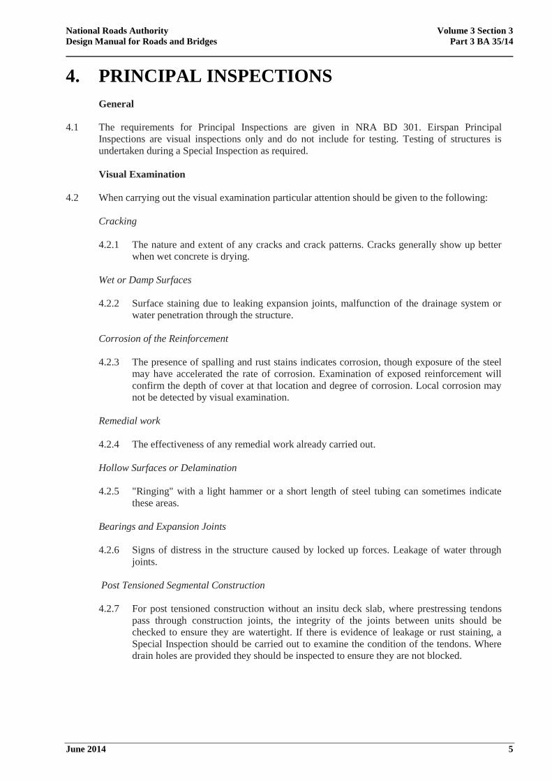
4.1 The requirements for Principal Inspections are given in NRA BD 301. Eirspan Principal
Inspections are visual inspections only and do not include for testing. Testing of structures is
undertaken during a Special Inspection as required.
Visual Examination
4.2 When carrying out the visual examination particular attention should be given to the following:
Cracking
4.2.1 The nature and extent of any cracks and crack patterns. Cracks generally show up better
when wet concrete is drying.
Wet or Damp Surfaces
4.2.2 Surface staining due to leaking expansion joints, malfunction of the drainage system or
water penetration through the structure.
Corrosion of the Reinforcement
4.2.3 The presence of spalling and rust stains indicates corrosion, though exposure of the steel
may have accelerated the rate of corrosion. Examination of exposed reinforcement will
confirm the depth of cover at that location and degree of corrosion. Local corrosion may
not be detected by visual examination.
Remedial work
4.2.4 The effectiveness of any remedial work already carried out.
Hollow Surfaces or Delamination
4.2.5 "Ringing" with a light hammer or a short length of steel tubing can sometimes indicate
these areas.
Bearings and Expansion Joints
4.2.6 Signs of distress in the structure caused by locked up forces. Leakage of water through
joints.
Post Tensioned Segmental Construction
4.2.7 For post tensioned construction without an insitu deck slab, where prestressing tendons
pass through construction joints, the integrity of the joints between units should be
checked to ensure they are watertight. If there is evidence of leakage or rust staining, a
Special Inspection should be carried out to examine the condition of the tendons. Where
drain holes are provided they should be inspected to ensure they are not blocked.
National Roads Authority Volume 3 Section 3
Design Manual for Roads and Bridges Part 3 BA 35/14
June 2014 6
5. SPECIAL INSPECTIONS
General
5.1 Where deterioration of concrete members is observed or detected during Principal Inspections, or
if the presence of ASR is suspected, the Engineer should consider a Special Inspection. The
objective is to determine the cause and extent of deterioration for the purpose of assessing
structural integrity and specifying remedial measures. Special Inspections may require a staged
approach i.e. a preliminary investigation followed by monitoring or a detailed investigation or
both.
Preliminary Investigation
5.2 The first step in a preliminary investigation is to refer to all previous records including the
Principal Inspection report, previous Special Inspection reports and Structural Assessment reports.
If information from a recent Principal Inspection is not available, it may be necessary to carry out
a visual examination. This will establish the need for monitoring or insitu and laboratory testing.
Monitoring
5.3 After the preliminary investigation it may be necessary to monitor the structure before coming to a
decision on the need for a more comprehensive investigation. The rate of deterioration should be
assessed in relation to external influences. In the case of cracks where more information is
required before a diagnosis is made, periodic measurement will indicate if movement is still
taking place or has ceased.
5.4 During the resurfacing/waterproofing of reinforced concrete bridge decks the opportunity should
be taken to carry out chloride ion and half-cell potential tests. This allows bridge decks to be
monitored without damage to the waterproof membrane and disruption to traffic. One chloride test
should be taken at 3 metre intervals per lane width. Additional tests should be carried out when
half-cell potential measurements are numerically greater than -350mV (with respect to a
copper/copper sulphate reference electrode) and at vulnerable areas such as expansion joints and
kerb lines.
Detailed Investigation
5.5 The Engineer should prepare a schedule of sampling and testing based upon the recommendations
given in Section 6. On large projects or where deterioration is severe, a pilot investigation should
first be carried out to determine the types and numbers of tests required.
Post Tensioned Segmental Construction
5.6 Where a Special Inspection is required to examine the condition of tendons this should be carried
out by careful selective drilling/water jetting and observation using an endoscope. To avoid
damage to the tendon an automatic-stop drill should be used. All voids within post tensioned
segmental decks should be provided with drainage holes (refer to Section 9).
National Roads Authority Volume 3 Section 3
Design Manual for Roads and Bridges Part 3 BA 35/14
June 2014 7
6. TESTING
General
6.1 All sampling and testing should be carried out by specialist testing firms or laboratories approved
by the Irish National Accreditation Board (INAB) or by equivalent accreditation bodies of
member states of the European Union. Test information is of fundamental importance in assessing
the condition of a structure and the likelihood of reinforcement corrosion. Tests should be
accurately related to their location in the structure and it is recommended that the test area is
gridded at 500mm intervals, or other convenient spacing for reference.
Condition of Concrete
General
6.2 A core with a diameter of 100mm is required for compression testing, but cores of 50mm diameter
can also provide useful information on quality where 100mm cores are impracticable. Drilling,
core cutting and making-good of core holes and holes for chloride tests, should be carried out
under the supervision of the Engineer to ensure that the integrity of the structure is not affected.
6.2.1 Cores can provide information on:
(a) strength (6.2.2)
(b) compaction
(c) crack geometry
(d) cement content (6.2.3)
(e) water/cement ratio (6.2.4)
(f) aggregate type
(g) carbonation (6.2.5)
(h) chloride content (6.3.2)
(i) alkali-silica reaction (10)
Strength
6.2.2 Tests for strength on cores should comply with IS EN 12504-1. The pull out test and
the Schmidt Hammer are in-situ methods of assessing concrete quality at the surface;
the results give a comparative guide to strength. Ultrasonic methods (IS EN 12504-4)
can also be used where appropriate to give an indication of strength.
Cement Content
6.2.3 It is normally possible to determine the cement content to within ±15% of that
originally used in the mix. Tests should be carried out in accordance with BS 1881:
Part 124 and BS 4551.
National Roads Authority Volume 3 Section 3
Design Manual for Roads and Bridges Part 3 BA 35/14
June 2014 8
Water/Cement Ratio
6.2.4 A test method for determining the water/cement ratio in the mix is described in BS
1881: Part 124.
Carbonation of the Concrete
6.2.5 The extent of carbonation should be determined by spraying a fractured surface with
phenolphthalein indicator. The colour of any carbonated concrete is unchanged but the
uncarbonated material turns purple. As the pH value at which the colour change occurs
is about 9, this test indicates concrete which has ceased to be protective. The depth of
carbonation may also be determined by petrographic examination. The rate of
carbonation varies with age, exposure and quality of concrete, which will influence
choice of sample location.
Assessment of Corrosion Risk
6.3 Corrosion risk can be assessed using the following methods.
Cover meter
6.3.1 The time to initiation of corrosion is reduced when cover to the reinforcement is less than
specified. The depth of cover afforded by the concrete will need to be measured using a
suitable cover meter. Measurements should be taken on a grid system, compatible with
the reinforcement arrangement. An average site accuracy of about ±15 per cent may be
expected with a maximum error of ± 5mm. A check to confirm that the instrument has
been properly calibrated should be carried out at a convenient location on the structure
before any field measurements are taken. This may be done using the cover meter to
record the cover and then breaking out the concrete at the same location to expose the
reinforcement so that a physical measurement of the actual cover can be recorded.
Corrections should be applied for bar diameters outside the range of 10mm to 32mm, high
yield bars, special cements, heavy or lightweight concretes and curved bars. Inaccuracies
can result from tying wire, dense or multi-layered reinforcement and the close proximity
of overhead power lines. The cover meter is particularly useful for determining the
location of reinforcement prior to core drilling.
Total Chloride Ion Content of the Concrete
6.3.2 Total chloride ion content is determined by analysing dust samples taken from holes
drilled into the concrete. For insitu concrete, holes should be 20-25mm in diameter.
Alternatively core samples may be used. For prestressed concrete members the position of
tendons and wires should first be located. Holes should be not greater than 10mm in
diameter. Guidance on frequency and location of sampling is given in BRE Digest 444
Part 2. Chemical analysis is performed by the method described in BS 1881: Part 124.
6.3.3 Results of chloride analysis can be presented as a profile, chloride concentration against
depth, and care must be taken to separate the incremental samples. The analysis provides
the total chloride ion content from all sources, both during construction and in service.
Most of the chloride that was present in the wet mix will have combined with other
constituents to form stable compounds.
National Roads Authority Volume 3 Section 3
Design Manual for Roads and Bridges Part 3 BA 35/14
June 2014 9
Half-Cell Potential
6.3.4 The half-cell potential method together with chloride ion content data enables the risk of
corrosion to be assessed. Corrosion potential measurements are made using a reference
electrode placed on the concrete surface, which is connected via a high impedance
voltmeter to the reinforcement. The method is described in ASTM C 876. By convention,
potentials are considered negative when measuring the steel with respect to the electrode.
Potentials numerically less than -200mV indicate a low probability of corrosion. The half-
cell potentials given in this Advice Note are in terms of the copper/copper sulphate
electrode. The interpretation of results requires experience and due account must be taken
not only of absolute values of current, but rate of change of potential and moisture content
of the concrete. Where concrete has been impregnated with iso-butyl silane there will be a
shift in half-cell potential measurements and due account of this must be taken in
interpreting the readings. Before carrying out measurements the As Built information for
the structure (Refer to NRA BD 02), if available, should be examined to determine
whether any concrete members have been impregnated.
Resistivity of the Concrete
6.3.5 Resistivity is related to the moisture content and quality of the concrete. Resistivity
measurements can give information which help in the interpretation of half-cell potential
tests made under the same conditions. Experience has shown that in regions where the
half-cell potential is numerically greater than -350mV (eg -400mV):
(a) If the resistivity is greater than 12,000 ohm cm, corrosion is unlikely.
(b) If the resistivity is in the range 5,000-12,000 ohm cm, corrosion is probable.
(c) If the resistivity is less than 5,000 ohm cm, corrosion is almost certain.
The technique is similar to that used for measuring soil resistivity and uses electrodes
temporarily attached to the concrete, across which measurements of voltage and current
are taken. As standardised equipment for this test is generally not yet available it is
recommended that where required, tests are carried out by an approved testing firm which
has developed its own apparatus and trained staff in its use. There are a large number of
possible factors which may affect electrical potential and resistivity measurements and
hence the actual values determined. An experienced testing firm will be aware of these.
Testing for Chloride Damage
6.4 The test areas given below are for guidance only. Within each test area depth of cover and half-
cell potential measurements should be taken on a 500 mm grid and dust samples for chloride
analysis taken from positions of numerically high half-cell potentials. This may be supplemented
if necessary by half-cell potential measurements over the whole member and spot chloride tests at
positions of numerically high half-cell potentials. Where appropriate, permanent connections to
the reinforcement should be made to facilitate half-cell testing.
Reinforced Concrete Piers, Abutments, Columns and Crossheads
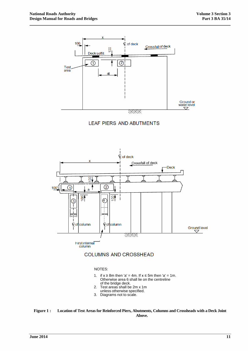
6.4.1 The test areas should be 2m x 1m. For members with a deck joint above, the test areas
should be located where staining has occurred and generally in accordance with Figure
1. Where these members are below deck joints and are also subjected to salt traffic
spray, the test areas shown in Figure 2 should also apply.
National Roads Authority Volume 3 Section 3
Design Manual for Roads and Bridges Part 3 BA 35/14
June 2014 10
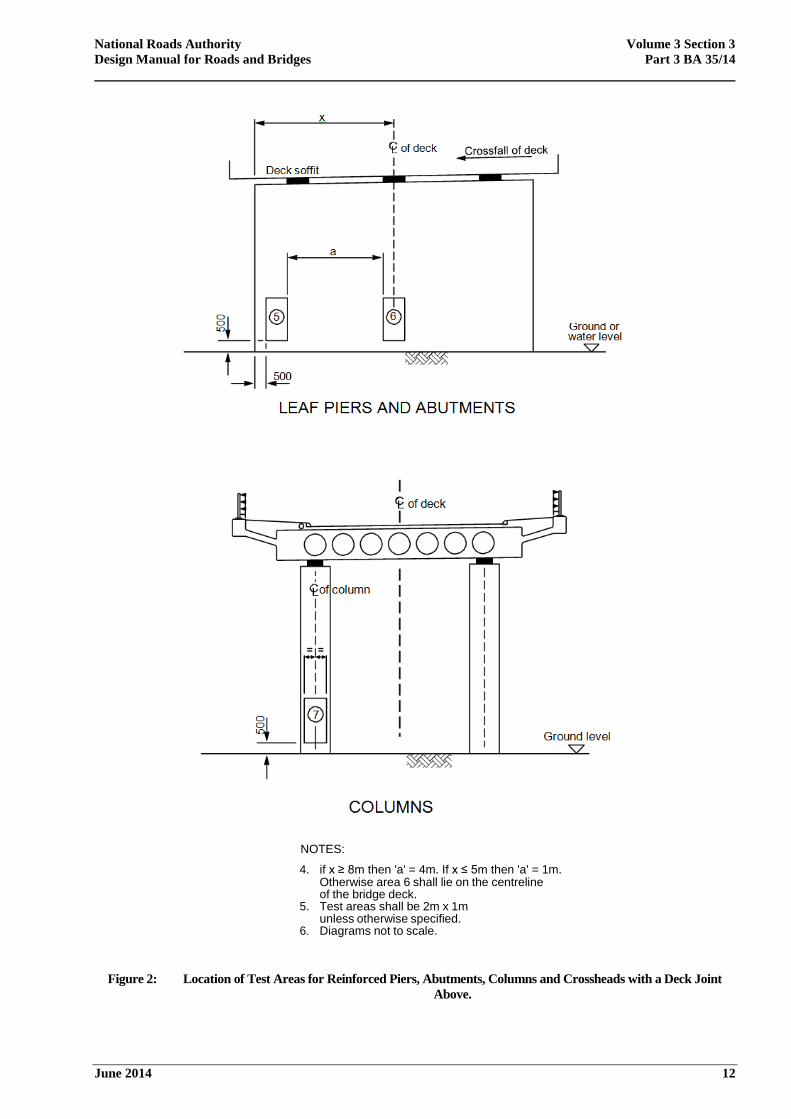
Reinforced Concrete Wingwalls and Retaining Walls
6.4.2 Where these members are subjected to salt traffic spray the test areas should be as for
leaf piers and abutments shown in Figure 2, except that the test area should be repeated
every 5m along a horizontal line.
Reinforced Concrete Parapets and Parapet Plinths
6.4.3 For reinforced concrete parapets subjected to salt traffic spray the test areas should be
on the traffic face. The test areas should be 2m x 1m or 2m x 0.5m or other convenient
dimensions, 100mm below the top edge of the concrete parapet and repeated every 5m
along a horizontal line. For reinforced concrete parapet plinths subjected to salt traffic
spray the test area should be 1m long and repeated every 5m along the length of the
plinth.
National Roads Authority Volume 3 Section 3
Design Manual for Roads and Bridges Part 3 BA 35/14
June 2014 11
NOTES:
1. if x ≥ 8m then 'a' = 4m. If x ≤ 5m then 'a' = 1m. Otherwise area 6 shall lie on the centreline of the bridge deck.
2. Test areas shall be 2m x 1m unless otherwise specified.
3. Diagrams not to scale.
Figure 1 : Location of Test Areas for Reinforced Piers, Abutments, Columns and Crossheads with a Deck Joint
Above.
National Roads Authority Volume 3 Section 3
Design Manual for Roads and Bridges Part 3 BA 35/14
June 2014 12
NOTES:
4. if x ≥ 8m then 'a' = 4m. If x ≤ 5m then 'a' = 1m. Otherwise area 6 shall lie on the centreline of the bridge deck.
5. Test areas shall be 2m x 1m unless otherwise specified.
6. Diagrams not to scale.
Figure 2: Location of Test Areas for Reinforced Piers, Abutments, Columns and Crossheads with a Deck Joint
Above.
National Roads Authority Volume 3 Section 3
Design Manual for Roads and Bridges Part 3 BA 35/14
June 2014 13
7. REPAIRS TO CHLORIDE CONTAMINATED
STRUCTRUES
General
7.1 It is not possible to forecast the life of concrete repairs. Where the results of insitu and laboratory
tests confirm that extensive and severe deterioration has occurred, an economic comparison
should be made between the cost of repair and replacing the member concerned.
7.2 Partial renewals, strengthening and repairs affecting the integrity or load carrying capacity of
existing structures are subject to the NRA Technical Acceptance procedures given in NRA BD 02.
7.3 Before any repairs are carried out, it is essential to ensure that all surface water leaves the
structure through properly provided drainage channels. It may be necessary to correct any
deficiencies in deck waterproofing and expansion joints by repair or replacement. Specialised
drainage systems have been developed for use in confined areas beneath deck joints.
Cracks
7.4 Repairs to cracks should not be carried out until the cause of cracking has been established and
dealt with, and monitoring (5.3) confirms that movement has ceased. Where deleterious cracking
has occurred in areas exposed to de-icing salts or in marine environments, and tests show that the
chloride content at the level of reinforcement exceeds 0.3 per cent by weight of cement, the
concrete should be removed (7.3). Sealing cracks by vacuum or injection methods alone will not
prevent chloride ingress and if protection is required these areas should also be impregnated.
Crack width measuring devices suitable for site use are now widely available.
Removal of Concrete
7.5 The Engineer should ensure that concrete removal is programmed to maintain structural integrity
and continuity of load transference in the member. Propping may be required in some instances,
particularly if it is considered necessary to simultaneously remove concrete from more than one
face of the member. Large areas of concrete may be removed using high pressure water jetting.
This method may not be appropriate in all situations due to difficulties with access and safety
arrangements. Care should be exercised in removing concrete from prestressed concrete members.
The position of tendons and wires should first be located, if necessary hand methods should be
used to expose tendons and assess their condition.
7.6 The extent of the repaired area will depend on the degree of contamination, visual examination
and the results of tests carried out. It will also be influenced by the interpretation of half-cell
potential and chloride measurements. Generally where chloride ion contents at the level of the
reinforcement exceed 0.3 per cent (total chloride ion content) by weight of cement and half-cell
potential measurements are numerically greater than -350mV, there is a high risk of corrosion
occurring and concrete in these areas should be removed.
7.7 To avoid 'patch' repairs the extent of concrete to be removed should be not less than 1 sq m in area
and should extend a minimum of 100mm along the bar beyond any corroded areas (pitted bars as
distinct from superficially rusty bars). The edges should be saw cut to a minimum depth of 10mm
to ensure that repaired areas are kept to well defined lines, which should also improve the overall
appearance of the repair. To enable the replacement concrete to be placed and to provide a
mechanical key, concrete should be removed for a distance of 30mm behind the reinforcement
over a length greater than its corroding length. If power hammers are to be used to remove
contaminated concrete, pick damage to reinforcing steel and micro-cracking in the remaining
concrete can be minimised by using a pointed tool.
National Roads Authority Volume 3 Section 3
Design Manual for Roads and Bridges Part 3 BA 35/14
June 2014 14
Cleaning of Reinforcement
7.8 Where possible, high pressure water jetting should be used or alternatively, wet blast cleaning.
Particular attention should be given to pits and crevices. Where significant loss of section has
occurred or pitting is extensive, reinforcement should be replaced. Additional reinforcement may
also be required to restore serviceability if mechanical damage to reinforcement has taken place
during removal of concrete. While repairs are being carried out, care should be taken to protect
exposed concrete substrates and reinforcement from salt spray from passing traffic.
Replacement Concrete
General
7.9 Concreting should be programmed to minimise shrinkage cracks. Wherever practical, deficient
cover to the reinforcement should be increased to meet current standards. To avoid ponding, all
horizontal surfaces i.e. tops of bearing shelves, piers and crossheads should be finished to a fall of
1 in 5.
7.10 Blended cement concretes properly placed and cured reduce the penetration rate of chloride ions
by changing the pore size distribution and chloride binding capacity of the cement paste. They
will assist in reducing the risk of chloride ion diffusing back into repaired areas. The use of
bagged aggregates and cement either singly or combined offer advantages for small amounts of
concrete mixed on site. It will also enable quality control to be maintained.
7.11 One of the potential problems with patch repair using cementitious materials is that pollutants,
including chloride ions, need to be prevented from causing harm. To overcome this problem,
patch-repaired structures can be coated using various proprietary surface coatings which will
prevent or retard the ingress of atmospheric pollutants. The coating needs to be completely ‘pin-
hole’ free but at the same time breathable.
7.12 Traditional patch repair is a short-term remedy for delaminated and spalled areas of concrete. It
inevitably introduces an ‘incipient anode’ effect due to the different electrochemical behaviour of
the reinforcement in the surrounding ‘old’ concrete (which may still be contaminated with
chlorides) and the ‘new’ concrete. This incipient anode effect can mean that the repair process is
never-ending as the patch repair addresses the symptoms but not the cause of the damage.
Water Cement Ratio and Curing
7.13 These have a profound effect on reducing permeability and increasing the durability of concrete. It
is important that a water/cement ratio of 0.4 is not exceeded. All repaired areas should be
continuously water cured for a minimum of 5 days after placing the concrete. This can be
achieved using a hose pipe 'sprinkler' system together with absorbent material covered by
polythene sheeting. Proprietary curing membranes do not provide a sufficient reservoir of water in
the early stages of curing and the pore blocking action of some may reduce the efficiency of
subsequent impregnation.
7.14 The importance of curing to reduce shrinkage cracking and increase the durability of concrete
repairs cannot be over emphasised. A separate item covering this work should be included in the
Bill of Quantities.
National Roads Authority Volume 3 Section 3
Design Manual for Roads and Bridges Part 3 BA 35/14
June 2014 15
Sprayed Concrete
7.15 In situations where reinforcement is not too congested sprayed concrete may be used subject to
NRA approval. Care should be taken to avoid creating 'shadow areas' behind the reinforcement. In
areas that are aesthetically sensitive, the final coat should be float finished to provide a smooth
surface. Further information is given in the Sprayed Concrete Association's Manual. Procedure
trials should be carried out to demonstrate the Contractor's competence, method of working and
mix design.
Electrochemical Repair Methods
7.16 Corrosion due to chloride contamination can also be repaired using electro-chemical repair
methods.
7.17 An advantage of electrochemical repair methods is that those areas of concrete which are
contaminated with chloride do not need to be broken out. Cathodic protection and chloride
extraction are two methods of electrochemical repair.
7.18 Details of cathodic protection for use in reinforced concrete road structures can be found in NRA
BA 83.
7.19 Chloride extraction requires an active electrical circuit to be established which forces the steel
reinforcement to become cathodic by providing an external anode. Chloride extraction is similar
to the impressed current cathodic protection detailed in NRA BA 83 in that an external electricity
supply is required. However, the drive voltage for chloride extraction is much higher than
cathodic protection and the anode is supplied as a series of surface mounted panels containing an
electrolyte.
7.20 The durability of repairs using chloride extraction is less well established than cathodic protection.
The efficiency of chloride extraction can vary significantly from structure to structure. Due to the
higher impressed current required for chloride extraction, this can increase the risk of alkali-silica
reaction. Also, the benefit of chloride extraction is considered as a short to medium term solution
and requires a number of repeat applications over the design life of a structure. Chloride
extraction should be chosen with care and discussed with the NRA before a final decision is made.
Minor Repairs
7.21 These include repairs to arrises and reinstatement of core holes etc.
Repair of Particular Elements
7.22 Details of repair to particular elements are given below.
Crossheads
7.22.1 Crossheads are particularly vulnerable to chloride attack from leaking expansion joints.
Where deterioration is severe it may be necessary to provide temporary supports while
repairs are carried out. This will require careful programming and traffic management.
For repairs to the sides and soffits of crossheads using high flow materials, strict
control should be exercised at all stages during mixing and placing of the concrete.
National Roads Authority Volume 3 Section 3
Design Manual for Roads and Bridges Part 3 BA 35/14
June 2014 16
Bridge Decks
7.22.2 Contamination of bridge decks generally occurs through failure or damage to the
waterproofing membrane. The location, extent and severity of the problem may only
become apparent when resurfacing/waterproofing is carried out. Damp patches on the
soffit while not necessarily indicating the position of faults in the membrane, can affect
half-cell potential measurements particularly on thin deck slabs. Where contamination
is severe, consideration should be given to replacing the deck slab. Where the concrete
replacement option has been chosen, high pressure water jetting will reduce the risk of
damage to the reinforcement. This is particularly relevant to thin deck slabs. Localised
contamination at expansion joints can occur due to inadequate sealing. All repaired
areas should be continuously water cured for a minimum of 5 days after placing of the
concrete, and be surface dry for a minimum of 24 hours before application of the
waterproof membrane.
National Roads Authority Volume 3 Section 3
Design Manual for Roads and Bridges Part 3 BA 35/14
June 2014 17
8. SURFACE IMPREGNATION
8.1 Concrete is not impermeable to the migration of chloride ions. It is possible that without
protection, soundly constructed and properly maintained structures subjected to sustained chloride
attack will eventually deteriorate during their service life.
8.2 Impregnation is carried out by spraying concrete surfaces with a hydrophobic material that
achieves IS EN 1504-2 values for hydrophobic impregnation of concrete. This produces a water-
repellent but vapour-permeable layer that inhibits the ingress of water and chloride ions.
Impregnation is known to be effective for at least 15 years provided it is applied correctly. Longer
service lives are anticipated. However it is considered advisable to assume that re-application may
be necessary after about 20 years.
8.3 The depth of penetration will vary depending on concrete quality and moisture content. To obtain
feedback, a record should be kept of the quantity of material used on treated areas and forwarded
to the National Roads Authority.
8.4 After curing, the whole of repaired structural members including the tops of piers, crossheads and
bearing shelves should be impregnated. Graffiti and encrusted surface deposits i.e. algae should be
removed by light dry grit blasting or wire brushing. Areas with cracks not exceeding 0.3mm in
width should be waterproofed by impregnation. Bridge deck surfaces which are to be
waterproofed in accordance with NRA BD 47 should not be treated. A minimum interval of 14
days after placing the concrete is required before impregnation to allow the concrete pore
structure to develop. Further information can be found in NRA MCDRW 1700 and NRA
MCDRW 5500.
National Roads Authority Volume 3 Section 3
Design Manual for Roads and Bridges Part 3 BA 35/14
June 2014 18
9. DRAINING OF VOIDS WITHIN BRIDGE DECKS
9.1 Collection of water within the voids of bridge decks has occurred in some instances. Water
finding its way into the voids is likely to remain there unless provision has been made for
drainage. It will increase the risk of corrosion of the steel reinforcement and possibly reduce the
live load carrying capacity of the bridge. Voids within existing bridge decks should therefore be
provided with drainage holes at the earliest opportunity.
9.2 Four types of non-recoverable void formers have been used in cellular or voided bridge decks:
(a) Spirally wound corrugated steel tubes.
(b) Waxed cardboard tubes and boxes.
(c) Timber.
(d) Expanded polystyrene void formers to any shape.
9.3 The following methods have been used to provide internal formwork to precast pretensioned box
beams:
(a) Recoverable formwork where the concrete is cast in two stages.
(b) Recoverable, tensioned, high-tensile wire wrapped with wire netting followed by
polythene sheets.
(c) Permanent formwork of hollow prefabricated box formers.
(d) Permanent formwork of expanded polystyrene.
9.4 Precast pre-tensioned U beams formed using collapsible steel forms and pseudo-box construction
using M beams should both be drained.
9.5 As-built Contract Drawings should be examined to verify the method used to form the voids and
the position of tendons and reinforcement. The latter should be verified by non-destructive testing
before any drilling is started. For voided and cellular bridge decks one 22mm diameter hole
should be drilled, while for precast pre-tensioned box, U beams and pseudo-box construction, two
15-20mm diameter holes should be drilled near each end on the centre line of each void or at the
low point away from adjacent vertical concrete members using a small gauge diamond drill.
9.6 Before commencing drilling operations as-built Contract Drawings should be checked for the
locations of any Statutory Undertakers Services i.e. gas, water, electricity, telephone etc., and their
positions confirmed on site where they are in the vicinity of the holes to be drilled. Extreme
caution should be exercised during the drilling operation to avoid causing damage to tendons.
Water held in deck voids can be highly alkaline and consequently potentially harmful. Precautions
should be taken to avoid the water coming into contact with eyes or skin. If water is present in the
void it should be tested for its chloride ion content, its source of entry should be identified if
possible, and measures taken to prevent further ingress into the voids. If there is any evidence of
rust staining or corrosion to reinforcement then consideration should be given to treatment or
repair of such areas.
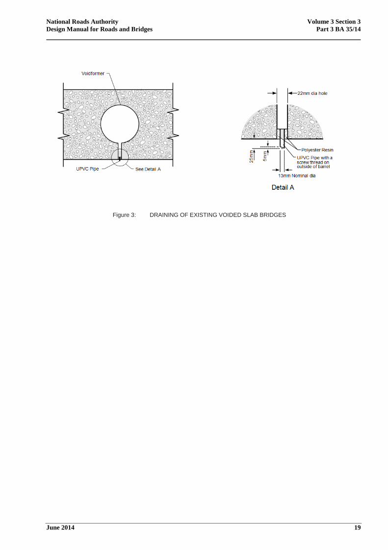
9.7 Once the holes have been drilled a 13mm nominal bore and 50mm length tube of inert material
e.g. UPVC or similar with a screw thread should be fixed into the hole using a polyester resin so
that it projects 25mm below the soffit (or lesser dimension where the headroom is affected), as
shown in Figure 3 for a circular voided slab bridge deck.
National Roads Authority Volume 3 Section 3
Design Manual for Roads and Bridges Part 3 BA 35/14
June 2014 19
Figure 3: DRAINING OF EXISTING VOIDED SLAB BRIDGES
National Roads Authority Volume 3 Section 3
Design Manual for Roads and Bridges Part 3 BA 35/14
June 2014 20
10. ALKALI – SILICA REACTION
Introduction
10.1 In 1988 The Institution of Engineers of Ireland (now Engineers Ireland) and The Irish Concrete
Society established a joint working party to examine alkali silica reaction (ASR) in concrete in the
Republic of Ireland. In 1989, a questionnaire was widely circulated throughout Ireland to collect
any available data about concrete significantly affected by ASR. No damage was reported. The
joint working party published their report in 1991. Following the publication of IS EN 206-1 in
2001, the joint working party reconvened to review developments and again found that no cases
of deleterious ASR were reported.
In the UK, The Institution of Structural Engineers (IStructE) published guidance on the appraisal
of the structural effects of ASR.
10.2 ASR is an expansive chemical change causing cracking in hardened concrete. Reactive silica
present in some aggregates combines with the alkali in the cement when there is a sufficiently
high concentration of hydroxyl ions in the pore solution. The reaction product of this combination
is alkali-silica gel which swells as it imbibes water and can exert pressure, causing cracking in the
concrete. The gel may form in relatively dry conditions but for the reaction to cause damage to the
concrete, there must be a sufficient supply of moisture available. Limiting the supply of water will
generally slow down the progress of ASR though it can occur in the presence of water vapour
alone. Thus it is important to detect ASR at an early stage so that measures can be taken to
exclude water and de-icing salts in order to keep concrete structures in service as long as possible.
The presence of deleterious ASR has not been found to be a significant problem in Ireland.
However, the following approach should be taken to address ASR should it become a problem in
the future.
Identification
10.3 ASR can progress at very different rates and affected structures may take a long time to become
unserviceable, with some never reaching that condition. However, it is necessary to identify and
monitor the progress of ASR and thereby be in a position to take positive action to prevent
deterioration leading to a structure becoming unserviceable during its lifetime. Regular
monitoring of affected structures will also lead to the establishment of a comprehensive overview
of the national situation with respect to ASR.
10.4 When ASR is suspected in the course of Principal Inspections, either because of signs of
deterioration or other factors, a Special Inspection should be carried out to identify its presence
positively. Visual inspection alone cannot confirm or discount the presence of ASR with any
certainty. The objectives of a Special Inspection are to establish whether or not the structure
exhibits any features which could be consistent with ASR, and also to identify and isolate any
features which indicate other mechanisms. Identification of ASR should only be undertaken by
specialist testing firms or laboratories accredited by the Irish National Accreditation Board
(INAB) or by equivalent accreditation bodies of member states of the European Union. Although
ASR may have serious implications for the future service life of the structure, it should be
remembered that in some circumstances other problems may be of more immediate concern, e.g.
reinforcement corrosion.
National Roads Authority Volume 3 Section 3
Design Manual for Roads and Bridges Part 3 BA 35/14
June 2014 21
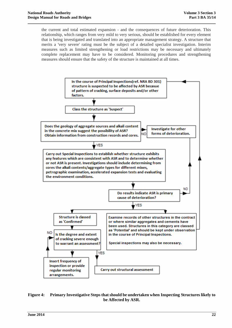
10.5 The flow chart in Figure 4 illustrates the primary investigative steps that should be undertaken
when inspecting structures thought to be affected by ASR. Definitions of three categories of ASR
used in the flow chart are as follows:
Suspect - structures which are suspected to be suffering from ASR due to the
presence of map-type cracking and/or other factors e.g. structures categorised as
'potential'.
Confirmed - structures where laboratory tests have confirmed the presence of ASR.
Potential - structures with similar aggregates/alkali contents to structures where ASR
has been confirmed.
The IStructE document describes the various steps to be undertaken during this process which can
lead to the identification of ASR as the primary cause of deterioration or eliminate it from further
consideration.
Management and Monitoring of Structures Affected by ASR
10.6 When ASR is confirmed records of other structures in the vicinity should be examined, especially
of those constructed in the same contract, to check whether or not the same aggregate and cement
were used. If records are not available the aggregate can be identified from cores 50mm diameter
by 100mm long. The choice of structures to be examined is determined by the number of different
contracts, known geology of aggregate sources in the areas, known local cement alkali contents
(at the time of construction if possible), and the number of structures in each contract. Where
aggregates are identified as potentially reactive, structures should be observed for signs of ASR in
the course of Principal Inspections and Special Inspections should follow if considered necessary.
The identification of aggregates susceptible to ASR and the results of these investigations are
important records for future investigatory work and should be included in the Special Inspection
Report. A revised copy of the structural inspection report should be forwarded to the NRA for
amendment of the Eirspan Database.
10.7 The need for a structural assessment should be considered if ASR is confirmed. The effects of
ASR on the ultimate strength of reinforced concrete is still a subject for research but vulnerable
details can be identified. Tests on concrete samples have indicated that ASR-affected concrete
generally has a high cube crushing strength for uncracked cores but has a markedly reduced
tensile strength as a result of the development of micro-cracking and internal stresses. The
expansion of ASR-affected concrete is restrained by reinforcement which sets up stresses and
strains in the concrete superimposed upon the structural effects. Details sensitive to the effects of
ASR should be carefully noted. These include half-joints, pile caps, zones of high bond stress and
concrete elements with little or no shear steel. Further guidance on the effects of ASR on concrete
structures is given in the IEI report.
10.8 Where ASR has been positively identified, the long-term programme for the management of
structures should also be reviewed. The current expansion should be determined by measurement
of the crack widths especially at structurally sensitive locations. If possible, overall structural
dimensions should also be monitored. The potential for expansion should be estimated from
expansion testing of cores. For rapid diagnosis, the expansion testing is normally carried out at
38°C and 100% RH, but there is increasing evidence that over the longer term, lower temperatures
will lead to greater expansion levels. The testing of cores for longer periods at lower temperatures
should therefore be considered in terms of the structural importance of the element being
investigated.
10.9 The IStructE report suggests generalised guidelines for the management and the monitoring
procedures for concrete structures suffering from ASR. It describes the relationship that exists
between the site environment, the reinforcement detailing, an expansion index - determined from
National Roads Authority Volume 3 Section 3
Design Manual for Roads and Bridges Part 3 BA 35/14
June 2014 22
the current and total estimated expansion - and the consequences of future deterioration. This
relationship, which ranges from very mild to very serious, should be established for every element
that is being investigated and translated into an appropriate management strategy. A structure that
merits a 'very severe' rating must be the subject of a detailed specialist investigation. Interim
measures such as limited strengthening or load restrictions may be necessary and ultimately
complete replacement may have to be considered. Monitoring procedures and strengthening
measures should ensure that the safety of the structure is maintained at all times.
Figure 4: Primary Investigative Steps that should be undertaken when Inspecting Structures likely to
be Affected by ASR.
National Roads Authority Volume 3 Section 3
Design Manual for Roads and Bridges Part 3 BA 35/14
June 2014 23
Repair of ASR Affected Structures
10.10 There may be practical or economic difficulties in repairing structures severely affected by ASR.
Where ASR has been positively identified and is extensive, long term planning should include the
possibility that replacement of parts or the whole of the structure may be necessary. It is essential
to slow down any further reaction taking place in the concrete, so the ingress of water must be
prevented in structures categorised as "confirmed" or "potential". If the potential for expansion
remains and water cannot be excluded then deterioration will continue. Any leaking drains and
expansion joints should be repaired and all surfaces including parapet upstands, bearing shelves
and vertical surfaces exposed to the atmosphere and at risk should be impregnated.
10.11 To be effective on structures categorised as "confirmed" or "potential", impregnation should be
applied immediately cracking is observed. Where expansion is severe and large fissures have
occurred the provision of a ventilated cladding would provide a more sheltered environment.
Attempts to remove and replace affected concrete should not be made until tests have confirmed
that expansion has ceased.
National Roads Authority Volume 3 Section 3
Design Manual for Roads and Bridges Part 3 BA 35/14
June 2014 24
11. REFERENCES
11.1 The National Roads Authority Publications
NRA BD 02 Technical Acceptance of Structures on Motorways and Other National Roads
NRA BD 47 Waterproofing and Surfacing of Concrete Bridge Decks
NRA BD 301 NRA Irish Structure Management System (EIRSPAN) - Principal
Inspection Manual
NRA BD 302 NRA Irish Structure Management System (EIRSPAN) – Routine Inspection
& Maintenance Manual
11.2 Irish Standards
IS EN 12350-5:2009 Testing fresh concrete. Flow table test
IS EN 12390 Testing hardened concrete
Part 1:2012. Shape, dimensions and other requirements for specimens and moulds.
Part 2:2009. Making and curing specimens for strength tests
Part 3:2009. Compressive strength of test specimens
Part 7:2000. Density of hardened concrete
IS EN 12504 Testing concrete in structures
Part 1:2009. Cored specimens, Taking, examining and testing in compression
Part 2:2004. Non-destructive testing. Determination of rebound number.
Part 3:2005. Determination of pull-out force
Part 4:2004. Determination of ultrasonic pulse velocity.
IS EN 1992: Design of Concrete Structures
Part 1: General rules and rules for buildings
(incorporating the Irish National Annex)
Part 2: Concrete bridges. Design and detailing rules
(incorporating the Irish National Annex)
11.3 British Standards (Published by BSI)
BS 1881: Testing Concrete
Part 121:1983 Method for determination of static modulus of elasticity in compression
Part 122:2011 Method for the determination of water absorption
Part 204: 1988 Recommendations on the use of electromagnetic cover meters
National Roads Authority Volume 3 Section 3
Design Manual for Roads and Bridges Part 3 BA 35/14
June 2014 25
Part 208:1996 Recommendations for the determination of the initial surface absorption of
concrete
Part 209:1990 Recommendations for the measurement of dynamic modulus of elasticity
BS 2000-14:1994, ISo 4262:1993 Methods of test for petroleum and its products.
Petroleum products. Determination of carbon residue. Ramsbottom method
11.4 American Society for Testing Materials (Published by ASTM)
ASTM C876 Method for Half-Cell Potentials of Uncoated Reinforcing Steel in Concrete.
11.5 UK Transport and Road Research Laboratory Publications
LR 953: A survey of site tests for the assessment of corrosion in reinforced concrete. P R
Vassie
LR 981: Case studies of the corrosion of reinforcement in concrete structures. R J
Woodward.
AG3: Microprocessor controlled multiple half-cell measurements. M A Winnett.
RR 81: Repair of cracked concrete: assessment of injection methods. A J Calder.
RR 150: Repair of cracked concrete: assessment of corrosion protection. A J Calder and D
M Thompson.
RR 109: Durability of concrete repairs: the effect of steel cleaning procedures. P R
Vassie.
The half-cell method of locating corroding reinforcement in concrete structures.
Application Guide 9. P R Vassie.
11.6 Building Research Establishment Publications
IP 21/86: Determination of chloride and cement of hardened concrete.
11.7 Other References
Structural effects of Alkali-Silica Reaction – Technical guidance on the appraisal of
existing structures, The Institution of Structural Engineers, 1992 (including 2010
addendum)
Structural effects of Alkali-Silica Reaction - Interim technical guidance on appraisal of
existing structures. The Institution of Structural Engineers, 1992, including the 2010
Addendum..
ICE Paper, ‘Corrosion mitigation of chloride-contaminated reinforced concrete structures:
a state-of-the-art review,’ by Sunil C. Das, Homayoon Sadeghi Pouya, Eshmaiel Ganjian
(Paper 900043)
National Roads Authority Volume 3 Section 3
Design Manual for Roads and Bridges Part 3 BA 35/14
June 2014 26
12. ENQUIRIES
12.1 All technical enquiries or comments on this document or any of the documents listed as forming
part of the NRA DMRB should be sent by e-mail to [email protected], addressed to the
following:
“Head of Network Management, Engineering Standards & Research
National Roads Authority
St Martin’s House
Waterloo Road
Dublin 4”
…………………………………………
Pat Maher
Head of Network Management,
Engineering Standards & Research

Ionad Ghnó Gheata na
Páirce,
Stráid Gheata na Páirce, Baile Átha Cliath 8, Éire
www.tii.ie
+353 (01) 646 3600
Parkgate Business Centre,
Parkgate Street,
Dublin 8, Ireland
+353 (01) 646 3601