Embed Size (px)
Citation preview
Inspiron 36463000 Series
Owner's Manual
Computer Model: Inspiron 3646Regulatory Model: D10SRegulatory Type: D10S001
Notes, Cautions, and WarningsNOTE: A NOTE indicates important information that helps you make better use of your computer.
CAUTION: A CAUTION indicates either potential damage to hardware or loss of data and tells you how to avoid the problem.
WARNING: A WARNING indicates a potential for property damage, personal injury, or death.
Copyright © 2014 Dell Inc. All rights reserved. This product is protected by U.S. and international copyright and intellectual property laws. Dell™ and the Dell logo are trademarks of Dell Inc. in the United States and/or other jurisdictions. All other marks and names mentioned herein may be trademarks of their respective companies.
2014 - 05
Rev. A00
Contents
Before Working Inside Your Computer.....................................7Before You Begin .............................................................................................. 7
Safety Instructions..............................................................................................7
Recommended Tools........................................................................................ 8
After Working Inside Your Computer........................................9
Technical Overview......................................................................10Inside View Of Your Computer....................................................................... 10
System-Board Components............................................................................ 11
Removing the Computer Cover ............................................... 12Procedure.........................................................................................................12
Replacing the Computer Cover ............................................... 13Procedure......................................................................................................... 13
Removing the Memory Module................................................ 14Prerequisites.....................................................................................................14
Procedure.........................................................................................................14
Replacing the Memory Module.................................................16Procedure......................................................................................................... 17
Post-requisites..................................................................................................17
Removing the Fan.........................................................................18Prerequisites.....................................................................................................18
Procedure.........................................................................................................18

Replacing the Fan.........................................................................20Procedure.........................................................................................................21
Post-requisites................................................................................................. 22
Removing the Front Bezel .........................................................23Prerequisites.....................................................................................................23
Procedure........................................................................................................ 24
Replacing the Front Bezel..........................................................26Procedure........................................................................................................ 26
Post-requisites.................................................................................................26
Removing the Drive Cage ..........................................................27Prerequisites.....................................................................................................27
Procedure........................................................................................................ 28
Replacing the Drive Cage...........................................................30Procedure........................................................................................................ 30
Post-requisites.................................................................................................30
Removing the Wireless Card......................................................31Prerequisites..................................................................................................... 31
Procedure.........................................................................................................31
Replacing the Wireless Card......................................................33Procedure.........................................................................................................33
Post-requisites................................................................................................. 33
Removing the Optical Drive...................................................... 34Prerequisites.....................................................................................................34
Procedure........................................................................................................ 34
Replacing the Optical Drive.......................................................35Procedure.........................................................................................................35
Post-requisites................................................................................................. 35
Removing the Hard Drive...........................................................36Prerequisites.....................................................................................................36
Procedure.........................................................................................................37
Replacing the Hard Drive........................................................... 38Procedure........................................................................................................ 38
Post-requisites.................................................................................................38
Removing the Front I/O-Panel................................................. 39Prerequisites.....................................................................................................39
Procedure........................................................................................................ 39
Replacing the Front I/O-Panel.................................................. 41Procedure.........................................................................................................41
Post-requisites................................................................................................. 41
Removing the Power-Button Module.....................................42Prerequisites.....................................................................................................42
Procedure........................................................................................................ 42
Replacing the Power-Button Module.....................................44Procedure........................................................................................................ 44
Post-requisites.................................................................................................44
Removing the Coin-Cell Battery.............................................. 45Prerequisites.....................................................................................................45
Procedure........................................................................................................ 46

Replacing the Coin-Cell Battery...............................................47Procedure.........................................................................................................47
Post-requisites................................................................................................. 47
Removing the System Board..................................................... 48Prerequisites.................................................................................................... 48
Procedure........................................................................................................ 48
Replacing the System Board..................................................... 50Procedure........................................................................................................ 50
Post-requisites.................................................................................................50
System Setup..................................................................................51Overview ..........................................................................................................51
Entering System Setup .................................................................................... 51
Clearing Forgotten Passwords........................................................................ 51
Prerequisites...............................................................................................52
Procedure...................................................................................................52
Post-requisites........................................................................................... 52
Clearing CMOS Settings.................................................................................. 53
Prerequisites...............................................................................................53
Procedure...................................................................................................53
Post-requisites........................................................................................... 54
Flashing the BIOS......................................................................... 55
Getting Help and Contacting Dell........................................... 56Self-Help Resources........................................................................................56
Contacting Dell................................................................................................56
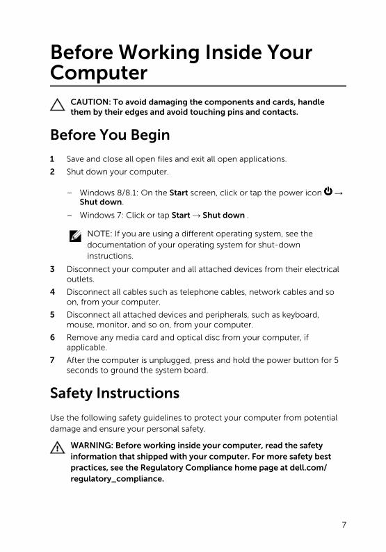
Before Working Inside Your Computer
CAUTION: To avoid damaging the components and cards, handle them by their edges and avoid touching pins and contacts.
Before You Begin
1 Save and close all open files and exit all open applications.
2 Shut down your computer.
– Windows 8/8.1: On the Start screen, click or tap the power icon → Shut down.
– Windows 7: Click or tap Start → Shut down .
NOTE: If you are using a different operating system, see the documentation of your operating system for shut-down instructions.
3 Disconnect your computer and all attached devices from their electrical outlets.
4 Disconnect all cables such as telephone cables, network cables and so on, from your computer.
5 Disconnect all attached devices and peripherals, such as keyboard, mouse, monitor, and so on, from your computer.
6 Remove any media card and optical disc from your computer, if applicable.
7 After the computer is unplugged, press and hold the power button for 5 seconds to ground the system board.
Safety Instructions
Use the following safety guidelines to protect your computer from potential damage and ensure your personal safety.
WARNING: Before working inside your computer, read the safety information that shipped with your computer. For more safety best practices, see the Regulatory Compliance home page at dell.com/regulatory_compliance.
7

WARNING: Disconnect all power sources before opening the computer cover or panels. After you finish working inside the computer, replace all covers, panels, and screws before connecting to the power source.
CAUTION: To avoid damaging the computer, make sure that the work surface is flat and clean.
CAUTION: To avoid damaging the components and cards, handle them by their edges and avoid touching pins and contacts.
CAUTION: Only a certified service technician is authorized to remove the computer cover and access any of the components inside the computer. See the safety instructions for complete information about safety precautions, working inside your computer, and protecting against electrostatic discharge.
CAUTION: Before touching anything inside your computer, ground yourself by touching an unpainted metal surface, such as the metal at the back of the computer. While you work, periodically touch an unpainted metal surface to dissipate static electricity, which could harm internal components.
CAUTION: When you disconnect a cable, pull on its connector or on its pull-tab, not on the cable itself. Some cables have connectors with locking tabs or thumb-screws that you must disengage before disconnecting the cable. When disconnecting cables, keep them evenly aligned to avoid bending any connector pins. When connecting cables, make sure that the ports and connectors are correctly oriented and aligned.
CAUTION: To disconnect a network cable, first unplug the cable from your computer and then unplug the cable from the network device.
CAUTION: Press and eject any installed card from the media-card reader.
Recommended Tools
The procedures in this document may require the following tools:
• Philips screwdriver
• Plastic scribe
8
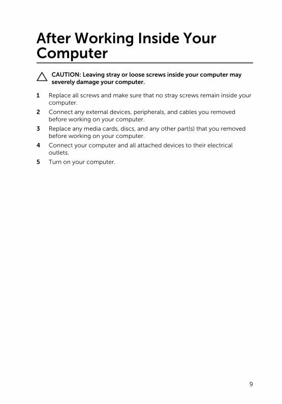
After Working Inside Your Computer
CAUTION: Leaving stray or loose screws inside your computer may severely damage your computer.
1 Replace all screws and make sure that no stray screws remain inside your computer.
2 Connect any external devices, peripherals, and cables you removed before working on your computer.
3 Replace any media cards, discs, and any other part(s) that you removed before working on your computer.
4 Connect your computer and all attached devices to their electrical outlets.
5 Turn on your computer.
9

Technical OverviewWARNING: Before working inside your computer, read the safety information that shipped with your computer and follow the steps in Before Working Inside Your Computer. After working inside your computer, follow the instructions in After Working Inside Your Computer. For more safety best practices, see the Regulatory Compliance home page at dell.com/regulatory_compliance.
Inside View Of Your Computer
1 front bezel 2 drive cage
3 optical drive 4 fan
5 system board 6 heat-sink assembly
10
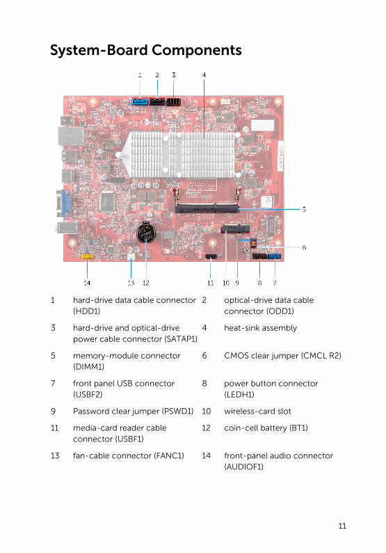
System-Board Components
1 hard-drive data cable connector (HDD1)
2 optical-drive data cable connector (ODD1)
3 hard-drive and optical-drive power cable connector (SATAP1)
4 heat-sink assembly
5 memory-module connector (DIMM1)
6 CMOS clear jumper (CMCL R2)
7 front panel USB connector (USBF2)
8 power button connector (LEDH1)
9 Password clear jumper (PSWD1) 10 wireless-card slot
11 media-card reader cable connector (USBF1)
12 coin-cell battery (BT1)
13 fan-cable connector (FANC1) 14 front-panel audio connector (AUDIOF1)
11
Removing the Computer Cover
WARNING: Before working inside your computer, read the safety information that shipped with your computer and follow the steps in Before Working Inside Your Computer. After working inside your computer, follow the instructions in After Working Inside Your Computer. For more safety best practices, see the Regulatory Compliance home page at dell.com/regulatory_compliance.
Procedure
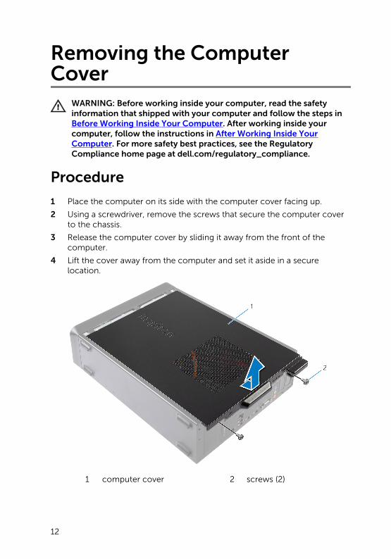
1 Place the computer on its side with the computer cover facing up.
2 Using a screwdriver, remove the screws that secure the computer cover to the chassis.
3 Release the computer cover by sliding it away from the front of the computer.
4 Lift the cover away from the computer and set it aside in a secure location.
1 computer cover 2 screws (2)
12

Replacing the Computer Cover WARNING: Before working inside your computer, read the safety information that shipped with your computer and follow the steps in Before Working Inside Your Computer. After working inside your computer, follow the instructions in After Working Inside Your Computer. For more safety best practices, see the Regulatory Compliance home page at dell.com/regulatory_compliance.
Procedure
1 Connect all the cables and fold the cables out of the way.
2 Ensure that no tools or extra parts are left inside the computer.
3 Align the tabs at the bottom of the computer cover with the slots located along the edge of the chassis.
4 Press the computer cover down and slide it towards the front of the computer.
5 Replace the screws that secure the computer cover to the chassis.
6 Place the computer in an upright position.
13
Removing the Memory ModuleWARNING: Before working inside your computer, read the safety information that shipped with your computer and follow the steps in Before Working Inside Your Computer. After working inside your computer, follow the instructions in After Working Inside Your Computer. For more safety best practices, see the Regulatory Compliance home page at dell.com/regulatory_compliance.
Prerequisites
Remove the computer cover.
Procedure
1 Locate the memory-module slot (DIMM) on the system board.
For more information on the location of the memory-module slot see, “System-Board Components”.
2 Use your fingertips to spread apart the securing clips on each end of the memory module slot until the memory module pops up.
14

3 Remove the memory module from the memory-module slot.
1 memory-module slot 2 memory module
3 securing clips (2)
15

Replacing the Memory ModuleWARNING: Before working inside your computer, read the safety information that shipped with your computer and follow the steps in Before Working Inside Your Computer. After working inside your computer, follow the instructions in After Working Inside Your Computer. For more safety best practices, see the Regulatory Compliance home page at dell.com/regulatory_compliance.
16

Procedure
1 Align the notch on the memory module with the tab on the memory-module slot.
2 Insert the memory module into the memory-module slot, and press the memory module down until it clicks into place.
NOTE: If you do not hear the click, remove the memory module and reinstall it.
1 memory module 2 memory module slot
3 notch 4 tab
Post-requisites
Replace the computer cover.
17
Removing the FanWARNING: Before working inside your computer, read the safety information that shipped with your computer and follow the steps in Before Working Inside Your Computer. After working inside your computer, follow the instructions in After Working Inside Your Computer. For more safety best practices, see the Regulatory Compliance home page at dell.com/regulatory_compliance.
Prerequisites
Remove the computer cover.
Procedure
1 Disconnect the fan cable from the system-board connector (FANC1).
For more information on the location of the fan cable connector, see “System-Board Components”.
2 Note the location of the fan on the heat sink assembly.
3 Disconnect the power and data cables from the connectors on the optical drive.
18
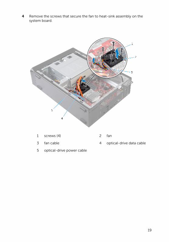
4 Remove the screws that secure the fan to heat-sink assembly on the system board.
1 screws (4) 2 fan
3 fan cable 4 optical-drive data cable
5 optical-drive power cable
19

Replacing the FanWARNING: Before working inside your computer, read the safety information that shipped with your computer and follow the steps in Before Working Inside Your Computer. After working inside your computer, follow the instructions in After Working Inside Your Computer. For more safety best practices, see the Regulatory Compliance home page at dell.com/regulatory_compliance.
20
Procedure
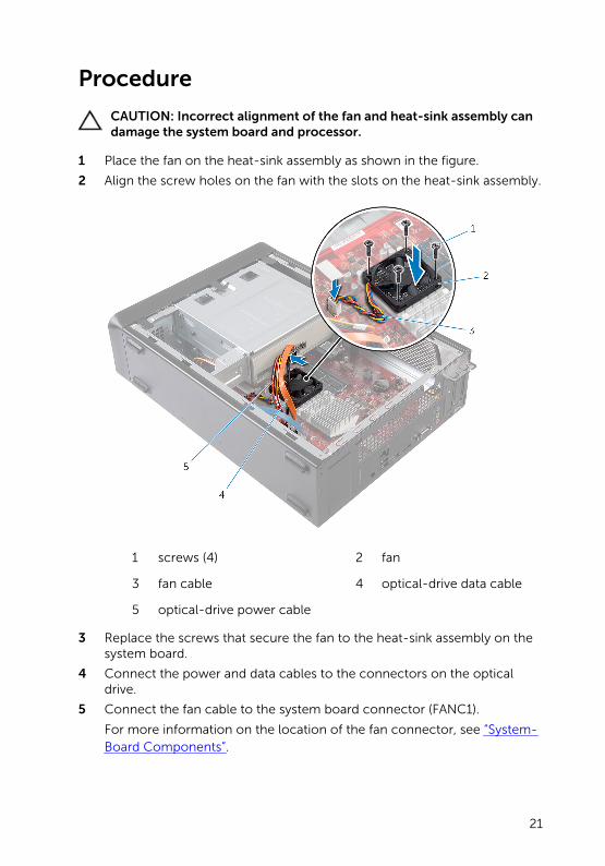
CAUTION: Incorrect alignment of the fan and heat-sink assembly can damage the system board and processor.
1 Place the fan on the heat-sink assembly as shown in the figure.
2 Align the screw holes on the fan with the slots on the heat-sink assembly.
1 screws (4) 2 fan
3 fan cable 4 optical-drive data cable
5 optical-drive power cable
3 Replace the screws that secure the fan to the heat-sink assembly on the system board.
4 Connect the power and data cables to the connectors on the optical drive.
5 Connect the fan cable to the system board connector (FANC1).
For more information on the location of the fan connector, see “System-Board Components”.
21

Post-requisites
Replace the computer cover.
22
Removing the Front Bezel WARNING: Before working inside your computer, read the safety information that shipped with your computer and follow the steps in Before Working Inside Your Computer. After working inside your computer, follow the instructions in After Working Inside Your Computer. For more safety best practices, see the Regulatory Compliance home page at dell.com/regulatory_compliance.
Prerequisites
Remove the computer cover.
23
Procedure
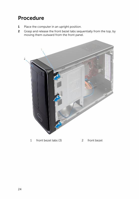
1 Place the computer in an upright position.
2 Grasp and release the front bezel tabs sequentially from the top, by moving them outward from the front panel.
1 front bezel tabs (3) 2 front bezel
24
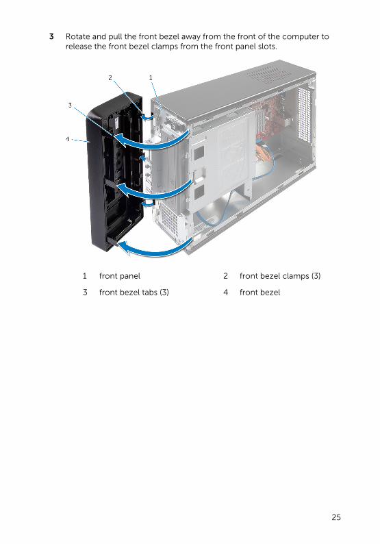
3 Rotate and pull the front bezel away from the front of the computer to release the front bezel clamps from the front panel slots.
1 front panel 2 front bezel clamps (3)
3 front bezel tabs (3) 4 front bezel
25
Replacing the Front BezelWARNING: Before working inside your computer, read the safety information that shipped with your computer and follow the steps in Before Working Inside Your Computer. After working inside your computer, follow the instructions in After Working Inside Your Computer. For more safety best practices, see the Regulatory Compliance home page at dell.com/regulatory_compliance.
Procedure
1 Align and insert the front bezel clamps into the front panel slots.
2 Rotate the front bezel towards the computer until the front bezel tabs snap into place.
Post-requisites
Replace the computer cover.
26
Removing the Drive Cage WARNING: Before working inside your computer, read the safety information that shipped with your computer and follow the steps in Before Working Inside Your Computer. After working inside your computer, follow the instructions in After Working Inside Your Computer. For more safety best practices, see the Regulatory Compliance home page at dell.com/regulatory_compliance.
Prerequisites
1 Remove the computer cover.
2 Remove the front bezel.
3 Place the computer on its side to access the drive cage.
27
Procedure
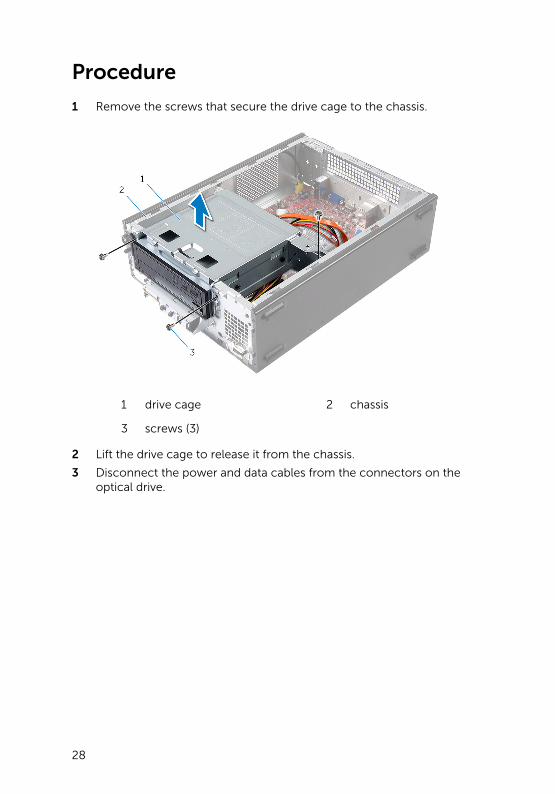
1 Remove the screws that secure the drive cage to the chassis.
1 drive cage 2 chassis
3 screws (3)
2 Lift the drive cage to release it from the chassis.
3 Disconnect the power and data cables from the connectors on the optical drive.
28

4 Disconnect the power and data cables from the connectors on the hard drive.
1 drive cage 2 optical-drive power cable
3 optical-drive data cable 4 hard-drive power cable
5 hard-drive data cable
5 Lift the drive cage away from the chassis.
6 Remove the optical drive.
7 Remove the hard drive.
29
Replacing the Drive CageWARNING: Before working inside your computer, read the safety information that shipped with your computer and follow the steps in Before Working Inside Your Computer. After working inside your computer, follow the instructions in After Working Inside Your Computer. For more safety best practices, see the Regulatory Compliance home page at dell.com/regulatory_compliance.
Procedure
1 Replace the optical drive.
2 Replace the hard drive.
3 Connect the power and data cables to the connectors on the optical drive.
4 Connect the power and data cables to the connectors on the hard drive.
5 Gently slide the drive cage into the chassis.
6 Replace the screws that secure the drive cage to the chassis.
Post-requisites
1 Replace the front bezel.
2 Replace the computer cover.
30
Removing the Wireless CardWARNING: Before working inside your computer, read the safety information that shipped with your computer and follow the steps in Before Working Inside Your Computer. After working inside your computer, follow the instructions in After Working Inside Your Computer. For more safety best practices, see the Regulatory Compliance home page at dell.com/regulatory_compliance.
Prerequisites
1 Remove the computer cover.
2 Remove the front bezel.
3 Follow the procedure from step 1 to step 5 in “Removing the drive cage”.
Procedure
1 Locate the wireless mini-card.
For more information on the location of the wireless mini-card slot, see “System-Board Components”.
2 Disconnect the antenna cables from the wireless mini-card.
31
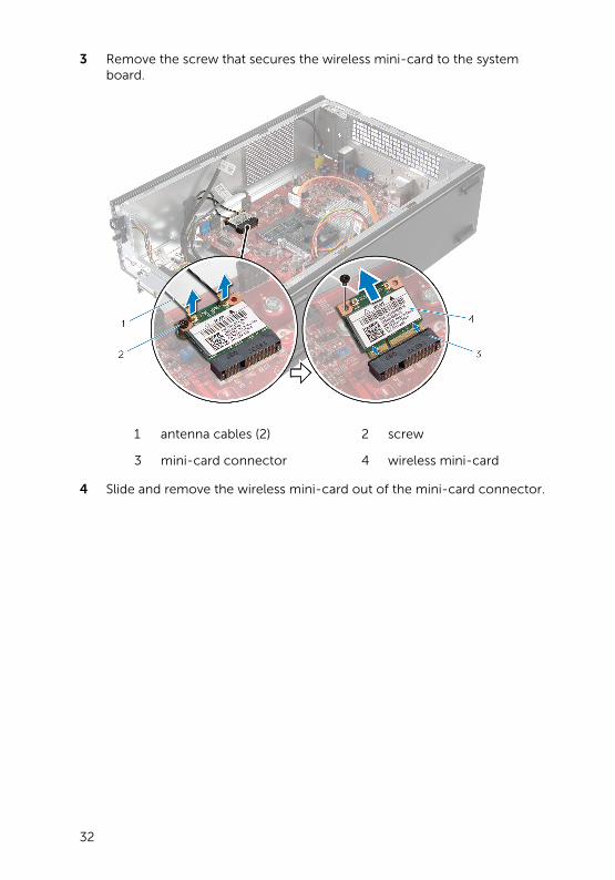
3 Remove the screw that secures the wireless mini-card to the system board.
1 antenna cables (2) 2 screw
3 mini-card connector 4 wireless mini-card
4 Slide and remove the wireless mini-card out of the mini-card connector.
32
Replacing the Wireless CardWARNING: Before working inside your computer, read the safety information that shipped with your computer and follow the steps in Before Working Inside Your Computer. After working inside your computer, follow the instructions in After Working Inside Your Computer. For more safety best practices, see the Regulatory Compliance home page at dell.com/regulatory_compliance.
Procedure
CAUTION: To avoid damage to the wireless mini-card, do not place any cables under it.
1 Locate the wireless mini-card slot.
For more information on the location of the wireless mini-card slot, see “System-Board Components”.
2 Align the notch on the wireless mini-card with the tab on the mini-card connector.
3 Slide the wireless mini-card at an angle into the system-board connector.
4 Press the other end of the wireless mini-card down and replace the screw that secures the wireless mini-card to the system board.
5 Connect the antenna cables to the wireless mini-card.
The following table provides the antenna-cable color scheme for the wireless mini-card supported by your computer.
Connectors on the wireless card Antenna-cable color
Main (white triangle) White
Auxiliary (black triangle) Black
Post-requisites
1 Follow the procedure from step 3 to step 6 in “Replacing the drive cage”.
2 Replace the front bezel.
3 Replace the computer cover.
33
Removing the Optical DriveWARNING: Before working inside your computer, read the safety information that shipped with your computer and follow the steps in Before Working Inside Your Computer. After working inside your computer, follow the instructions in After Working Inside Your Computer. For more safety best practices, see the Regulatory Compliance home page at dell.com/regulatory_compliance.
Prerequisites
1 Remove the computer cover.
2 Remove the front bezel.
3 Follow the procedure from step 1 to step 5 in “Removing the drive cage”.
Procedure
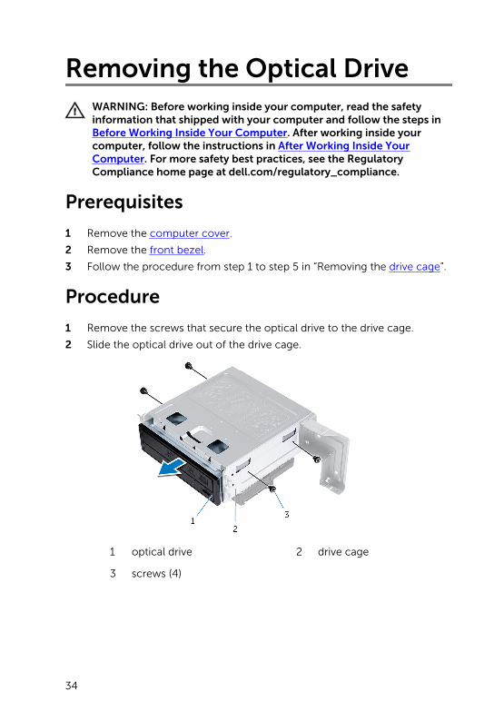
1 Remove the screws that secure the optical drive to the drive cage.
2 Slide the optical drive out of the drive cage.
1 optical drive 2 drive cage
3 screws (4)
34

Replacing the Optical DriveWARNING: Before working inside your computer, read the safety information that shipped with your computer and follow the steps in Before Working Inside Your Computer. After working inside your computer, follow the instructions in After Working Inside Your Computer. For more safety best practices, see the Regulatory Compliance home page at dell.com/regulatory_compliance.
Procedure
1 Slide the optical drive into the drive cage.
2 Align the screw holes on the optical drive with the screw holes on the drive cage.
3 Replace the screws that secure the optical drive to the drive cage.
Post-requisites
1 Follow the procedure from step 3 to step 6 in “Replacing the drive cage”.
2 Replace the front bezel.
3 Replace the computer cover.
35
Removing the Hard DriveWARNING: Before working inside your computer, read the safety information that shipped with your computer and follow the steps in Before Working Inside Your Computer. After working inside your computer, follow the instructions in After Working Inside Your Computer. For more safety best practices, see the Regulatory Compliance home page at dell.com/regulatory_compliance.
CAUTION: Hard drives are fragile. Exercise care when handling the hard drive.
CAUTION: To avoid data loss, do not remove the hard drive while the computer is in Sleep or On state.
Prerequisites
1 Remove the computer cover.
2 Remove the front bezel.
3 Follow the procedure from step 1 to step 5 in “Removing the drive cage”.
36

Procedure
1 Remove the screws that secure the hard-drive brackets to the hard-drive.
2 Push and slide the hard-drive off the hard-drive brackets.
1 hard-drive 2 hard-drive assembly
3 screws (4)
37
Replacing the Hard DriveWARNING: Before working inside your computer, read the safety information that shipped with your computer and follow the steps in Before Working Inside Your Computer. After working inside your computer, follow the instructions in After Working Inside Your Computer. For more safety best practices, see the Regulatory Compliance home page at dell.com/regulatory_compliance.
CAUTION: Hard drives are fragile. Exercise care when handling the hard drive.
Procedure
1 Align the screw holes on the hard-drive with the screw holes on the hard-drive brackets.
2 Replace the screws that secure the hard-drive brackets to the hard-drive.
3 Slide the hard-drive assembly into the chassis.
4 Replace the screws that secure the hard-drive assembly to the chassis.
Post-requisites
1 Follow the procedure from step 3 to step 6 in “Replacing the drive cage”.
2 Replace the front bezel.
3 Replace the computer cover.
38
Removing the Front I/O-PanelWARNING: Before working inside your computer, read the safety information that shipped with your computer and follow the steps in Before Working Inside Your Computer. After working inside your computer, follow the instructions in After Working Inside Your Computer. For more safety best practices, see the Regulatory Compliance home page at dell.com/regulatory_compliance.
Prerequisites
1 Remove the computer cover.
2 Remove the front bezel.
3 Follow the procedure from step 1 to step 5 in “Removing the drive cage”.
Procedure
CAUTION: Be careful when sliding the front I/O panel out of the computer to avoid damaging the connectors and the cable routing clips.
NOTE: Note the routing of all cables as you remove them so that you can re-route them correctly after you replace the front I/O panel.
1 Disconnect the front I/O panel cables from the system board connectors (AUDIOF1, USBF1, and USBF2).
For more information on the location of the cable connectors, see “System-Board Components”.
2 Remove the screw that secures the front I/O panel to the front panel.
39

3 Slide the front I/O panel towards the side as shown in the illustration to release the clamps from the front panel and pull it away.
1 front I/O panel clamps (4) 2 front I/O panel
3 screw 4 routing guides
5 front I/O panel cables (3)
40

Replacing the Front I/O-PanelWARNING: Before working inside your computer, read the safety information that shipped with your computer and follow the steps in Before Working Inside Your Computer. After working inside your computer, follow the instructions in After Working Inside Your Computer. For more safety best practices, see the Regulatory Compliance home page at dell.com/regulatory_compliance.
Procedure
1 Insert the front I/O panel clamps into the slots on the front panel.
2 Slide the front I/O panel towards the top. Ensure that the screw hole on the front I/O panel aligns with the screw hole on the front panel.
3 Replace the screw that secures the front I/O panel to the front panel.
4 Route the front I/O panel cables through the routing guides on the chassis.
5 Connect the front I/O panel cables to the system-board connectors (USBF1, USBF2, and AUDIOF1).
For more information on the location of the cable connectors, see “System-Board Components”.
Post-requisites
1 Follow the procedure from step 3 to step 6 in “Replacing the drive cage”.
2 Replace the front bezel.
3 Replace the computer cover.
41
Removing the Power-Button Module
WARNING: Before working inside your computer, read the safety information that shipped with your computer and follow the steps in Before Working Inside Your Computer. After working inside your computer, follow the instructions in After Working Inside Your Computer. For more safety best practices, see the Regulatory Compliance home page at dell.com/regulatory_compliance.
Prerequisites
1 Remove the computer cover.
2 Remove the front bezel.
3 Follow the procedure from step 1 to step 5 in “Removing the drive cage”.
Procedure
1 Disconnect the power-button module cable from the system-board connector (LEDH1).
For more information on the location of the cable connector, see “System-Board Components”.
2 Remove the power-button module cable from the routing guides on the chassis.
3 Press the power-button module tabs to release the power-button module from the front panel.
42
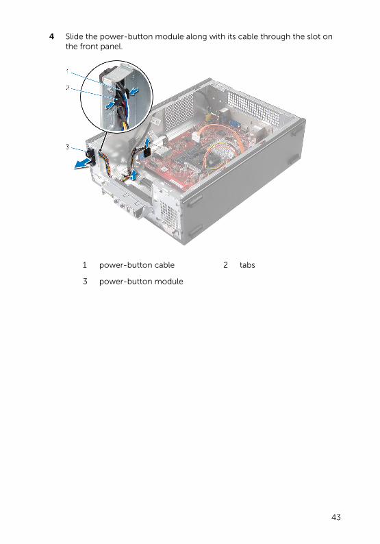
4 Slide the power-button module along with its cable through the slot on the front panel.
1 power-button cable 2 tabs
3 power-button module
43
Replacing the Power-Button Module
WARNING: Before working inside your computer, read the safety information that shipped with your computer and follow the steps in Before Working Inside Your Computer. After working inside your computer, follow the instructions in After Working Inside Your Computer. For more safety best practices, see the Regulatory Compliance home page at dell.com/regulatory_compliance.
Procedure
1 Align and push the power-button module tabs into the slots on the front panel.
2 Align the power-button module cable on the routing guides on the chassis.
3 Connect the power button module cable to the system board connector (LEDH1).
For more information on the location of the cable connector, see “System-Board Components”.
Post-requisites
1 Follow the procedure from step 3 to step 6 in “Replacing the drive cage”.
2 Replace the front bezel.
3 Replace the computer cover.
44
Removing the Coin-Cell Battery
WARNING: Before working inside your computer, read the safety information that shipped with your computer and follow the steps in Before Working Inside Your Computer. After working inside your computer, follow the instructions in After Working Inside Your Computer. For more safety best practices, see the Regulatory Compliance home page at dell.com/regulatory_compliance.
CAUTION: Removing the coin-cell battery resets the BIOS settings to default. It is recommended that you note the BIOS settings before removing the coin-cell battery.
Prerequisites
Remove the computer cover.
45
Procedure
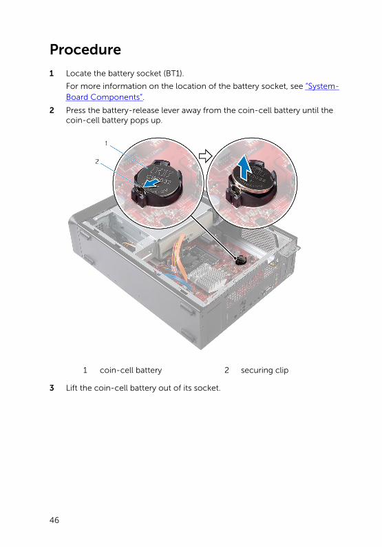
1 Locate the battery socket (BT1).
For more information on the location of the battery socket, see “System-Board Components”.
2 Press the battery-release lever away from the coin-cell battery until the coin-cell battery pops up.
1 coin-cell battery 2 securing clip
3 Lift the coin-cell battery out of its socket.
46
Replacing the Coin-Cell Battery
WARNING: Before working inside your computer, read the safety information that shipped with your computer and follow the steps in Before Working Inside Your Computer. After working inside your computer, follow the instructions in After Working Inside Your Computer. For more safety best practices, see the Regulatory Compliance home page at dell.com/regulatory_compliance.
Procedure
Insert a new coin-cell battery (CR2032) into the battery socket with the positive side facing up, and press the battery into place.
Post-requisites
Replace the computer cover.
47
Removing the System BoardWARNING: Before working inside your computer, read the safety information that shipped with your computer and follow the steps in Before Working Inside Your Computer. After working inside your computer, follow the instructions in After Working Inside Your Computer. For more safety best practices, see the Regulatory Compliance home page at dell.com/regulatory_compliance.
NOTE: Your computer’s Service Tag is stored in the system board. You must enter the Service Tag in the system setup after you replace the system board.
NOTE: Replacing the system board removes any changes you have made to the BIOS using System Setup. You must make the desired changes again after you replace the system board.
NOTE: Before disconnecting the cables from the system board, note the location of the connectors so that you can reconnect them correctly after you replace the system board.
Prerequisites
1 Remove the computer cover.
2 Remove the front bezel.
3 Follow the procedure from step 1 to step 5 in “Removing the drive cage”.
4 Remove the memory module.
5 Remove the wireless card.
6 Remove the fan.
Procedure
1 Disconnect the hard-drive data cable, optical-drive data cable, power-button cable, hard-drive and optical-drive power cable, front-panel USB cable, media-card reader cable, and front-panel audio cable from the system board.
For more information on the location of connectors, see “System-Board Components”.
2 Make note of the cable routing and remove the cables from the routing guides.
3 Remove the screws that secure the system board to the chassis.
48
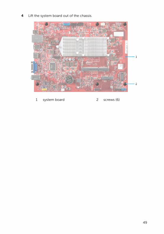
4 Lift the system board out of the chassis.
1 system board 2 screws (6)
49
Replacing the System BoardWARNING: Before working inside your computer, read the safety information that shipped with your computer and follow the steps in Before Working Inside Your Computer. After working inside your computer, follow the instructions in After Working Inside Your Computer. For more safety best practices, see the Regulatory Compliance home page at dell.com/regulatory_compliance.
NOTE: Your computer’s Service Tag is stored in the system board. You must enter the Service Tag in the system setup after you replace the system board.
Procedure
1 Gently place the system board into the chassis and slide it towards the back of the computer.
2 Align the screw holes on the system board with the screw holes on the chassis.
3 Replace the screws that secure the system board to the chassis.
4 Route and connect the hard-drive data cable, optical-drive data cable, power-button cable, hard-drive and optical-drive power cable, front-panel USB cable, media-card reader cable, and front-panel audio cable to the system board.
For more information on the location of connectors, see “System-Board Components”.
Post-requisites
1 Replace the fan.
2 Replace the wireless card.
3 Replace the memory module
4 Follow the procedure from step 3 to step 6 in “Replacing the drive cage”.
5 Replace the front bezel.
6 Replace the computer cover.
50
System Setup
Overview
CAUTION: Unless you are an expert computer user, do not change the settings in the system setup program. Certain changes can make your computer work incorrectly.
NOTE: Before you change system setup, it is recommended that you write down the system setup screen information for future reference.
Use system setup to:
• Get information about the hardware installed in your computer, such as the amount of RAM, the size of the hard drive, and so on
• Change the system configuration information
• Set or change a user-selectable option, such as the user password, type of hard drive installed, enabling or disabling base devices, and so on
Entering System Setup
1 Turn on (or restart) your computer.
2 During POST, when the DELL logo is displayed, watch for the F2 prompt to appear and then press <F2> immediately.
NOTE: The F2 prompt indicates that the keyboard has initialized. This prompt can appear very quickly, so you must watch for it, and then press <F2>. If you press <F2> before the F2 prompt, this
keystroke is lost. If you wait too long and the operating system logo appears, continue to wait until you see the operating system’s desktop. Then, turn off your computer and try again.
Clearing Forgotten Passwords
WARNING: Before working inside your computer, read the safety information that shipped with your computer and follow the steps in Before Working Inside Your Computer. After working inside your computer, follow the instructions in After Working Inside Your Computer. For more safety best practices, see the Regulatory Compliance home page at dell.com/regulatory_compliance.
51
Prerequisites
1 Remove the computer cover.
2 Follow the procedure from step 1 to step 5 in “Removing the drive cage”.
Procedure
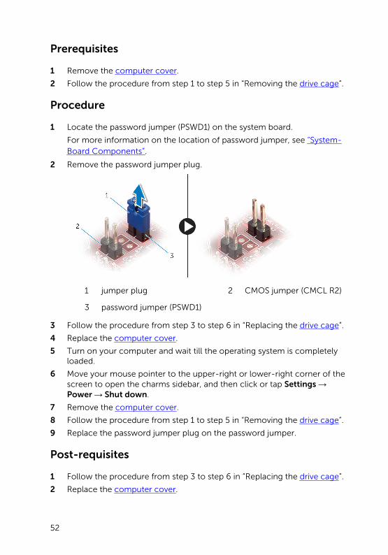
1 Locate the password jumper (PSWD1) on the system board.
For more information on the location of password jumper, see “System-Board Components”.
2 Remove the password jumper plug.
1 jumper plug 2 CMOS jumper (CMCL R2)
3 password jumper (PSWD1)
3 Follow the procedure from step 3 to step 6 in “Replacing the drive cage”.
4 Replace the computer cover.
5 Turn on your computer and wait till the operating system is completely loaded.
6 Move your mouse pointer to the upper-right or lower-right corner of the screen to open the charms sidebar, and then click or tap Settings → Power → Shut down.
7 Remove the computer cover.
8 Follow the procedure from step 1 to step 5 in “Removing the drive cage”.
9 Replace the password jumper plug on the password jumper.
Post-requisites
1 Follow the procedure from step 3 to step 6 in “Replacing the drive cage”.
2 Replace the computer cover.
52
Clearing CMOS Settings
WARNING: Before working inside your computer, read the safety information that shipped with your computer and follow the steps in Before Working Inside Your Computer. After working inside your computer, follow the instructions in After Working Inside Your Computer. For more safety best practices, see the Regulatory Compliance home page at dell.com/regulatory_compliance.
Prerequisites
1 Remove the computer cover.
2 Follow the procedure from step 1 to step 5 in “Removing the drive cage”.
Procedure
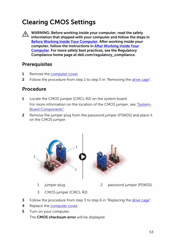
1 Locate the CMOS jumper (CMCL R2) on the system board.
For more information on the location of the CMOS jumper, see “System-Board Components”.
2 Remove the jumper plug from the password jumper (PSWD1) and place it on the CMOS jumper.
1 jumper plug 2 password jumper (PSWD1)
3 CMOS jumper (CMCL R2)
3 Follow the procedure from step 3 to step 6 in “Replacing the drive cage”.
4 Replace the computer cover.
5 Turn on your computer.
The CMOS checksum error will be displayed.
53
6 Press the F1 key to continue and wait till the operating system is completely loaded.
7 Move your mouse pointer to the upper-right or lower-right corner of the screen to open the charms sidebar, and then click or tap Settings → Power → Shut down.
8 Remove the computer cover.
9 Follow the procedure from step 1 to step 5 in “Removing the drive cage”.
10 Remove the jumper plug from the CMOS jumper and replace it on the password jumper.
Post-requisites
1 Follow the procedure from step 3 to step 6 in “Replacing the drive cage”.
2 Replace the computer cover.
54
Flashing the BIOSYou may need to flash (update) the BIOS when an update is available or when you replace the system board. To flash the BIOS:
1 Turn on the computer.
2 Go to dell.com/support.
3 If you have your computer's Service Tag, type your computer's Service Tag and click Submit.
If you do not have your computer's Service Tag, click Detect My Product to allow automatic detection of the Service Tag.
NOTE: If the Service Tag cannot be detected automatically, select your product under the product categories.
4 Click Get Drivers and Downloads.
5 Click View All Drivers.
6 In the Operating System drop-down, select the operating system installed on your computer.
7 Click BIOS.
8 Click Download File to download the latest version of the BIOS for your computer.
9 On the next page, select Single-file download and click Continue.
10 Save the file and once the download is complete, navigate to the folder where you saved the BIOS update file.
11 Double-click the BIOS update file icon and follow the instructions on the screen.
55

Getting Help and Contacting Dell
Self-Help Resources
You can get information and help on Dell products and services using these online self-help resources:
Self-Help Information Self-Help Options
Accessing Windows Help Windows 8/8.1 — Open the Search charm, type Help and Support in the search box and press <Enter>.
Windows 7 — Click Start → Help and Support.
Information about Dell products and services
See dell.com
Troubleshooting information, user manuals, setup instructions, product specifications, technical help blogs, drivers, software updates, and so on
See dell.com/support
Information about Microsoft Windows 8/8.1
See dell.com/windows8
Information about Microsoft Windows 7
Click Start → All Programs → Dell Help Documentation
Learn about your operating system, setting up and using your computer, data backup, diagnostics, and so on.
See Me and My Dell at dell.com/support/manuals.
Contacting Dell
To contact Dell for sales, technical support, or customer service issues, see dell.com/contactdell.
NOTE: Availability varies by country and product, and some services may not be available in your country.
56

NOTE: If you do not have an active internet connection, you can find contact information on your purchase invoice, packing slip, bill, or Dell product catalog.
57