Embed Size (px)
Citation preview
Instability Detection and Fall Avoidance for aHumanoid using Attitude Sensors and Reflexes
Reimund Renner and Sven BehnkeUniversity of Freiburg
Computer Science InstituteD-79110 Freiburg, Germany
{rrenner, behnke}@informatik.uni-freiburg.de
Abstract— Humanoid robots are inherently unstable becausetheir center of mass is high, compared to the support polygon’ssize. Bipedal walking currently works well only under controlledconditions with limited external disturbances. In less controlleddynamic environments, such as RoboCup soccer fields, externaldisturbances might be large. While some disturbances might betoo large to prevent a fall, some disturbances can be rejected byspecific rescue behaviors.
This paper proposes a method to detect instabilities thatoccur during omnidirectional walking. We model the readings ofattitude sensors using sinusoids. The model takes the gait targetvector into account. We estimate model parameters from a gaittest sequence and detect deviations of the actual sensor readingsfrom the model later on. These deviations are aggregated to aninstability indicator, which triggers one of two reflexes, basedon indicator strength. For small instabilities the robot is slowingdown, but continues walking. For stronger instabilities the robotstops and is brought into a stable posture with a low center ofmass. Walking continues as soon as the instability disappears.
We evaluated our approach in simulation by disturbing therobot with a variety of impulses. The results indicate that ourmethod is effective. For smaller disturbances, the probabilityof a fall could be reduced to zero. Most of the medium-sizeddisturbances could also be rejected.
I. INTRODUCTION
To act in the real world, a robot must be able to copewith the dynamics of the environment. Humanoid robots aremuch more flexible in comparison to wheeled or multi-leggedrobots, but are frequently not very stable during locomotion.Bipedal walking currently works well only under controlledconditions with limited external disturbances. This is due toa relatively high center of mass (CoM), compared to the sizeof the support polygon. Especially in the single-support phaseof bipedal walking small external disturbances are sometimessufficient to make a robot fall.
Although reliable standing up routines exist [1], falls shouldbe avoided, as falling robots might damage themselves or partsof their environment. Hence, it is important to be able to detectinstabilities and to prevent possible falls by specific rescuebehaviors. If a fall cannot be avoided, the robot might try tominimize the damage by going into a protective pose [2].
Our robot makes use of omnidirectional walking [3] for flex-ible locomotion and has acceleration and gyroscope sensors forlateral and sagittal planes, which are fused to estimates of thetilt in roll and pitch direction. We use this attitude estimateand its derivative to detect disturbances during walking.
The sensor readings captured during undisturbed omni-directional walking are modeled for some predefined gaitspeeds (support speeds). We model the means and standarddeviations of the two tilts and their derivatives (turning rate).Each model consists of the low-frequency coefficients of theFourier decomposition, which is synchronized to the gait cycle.Models for intermediate speeds are obtained by interpolationof the models of support speeds (support models).
We compute a stability indicator by comparing the actualsensor readings with the model for the actual gait speed. De-pending on indicator strength, one of two reflexes is activatedto stabilize the robot. For smaller instabilities, the robot isslowed down by decreasing the gait target speed. Thereby therobot still advances in the desired direction and we can furtheruse the attitude model to detect instabilities. For strongerinstabilities, a stop walk reflex is activated, which brings therobot into a standing posture with a lowered CoM in orderto regain stability. A dynamical instability indicator is usedto detect, weather the stop walk reflex is possible to stabilizethe robot. If not, other reactions like a lunge step or damageprotection are needed, which we do not present here. Thedynamic instability is based on the distance of the capturepoint (CP) ?? to the border of the support polygon.
Baltes et al. [4] proposed a method to stabilize the walkinggait of a humanoid robot using gyroscope sensors, which aresimilar to the derivative of our attitude sensors. However,they use it to control the gait itself by adjusting the startingpoints of the ankle patterns. The method is restricted to afixed gait speed. In contrast, our approach is valid for anyomnidirectional gait speed at limited ranges. We also take thetilt into account, which yields a better instability detection.
Another approach to prevent falls has been proposed byHohn et al. [5]. They use pattern recognition to detect andclassify instabilities. They also suggest that the ZMP haslittle significance as an instability indicator. The classificationuses feature vectors, consisting of the linear and rotationalvelocity and the tilt of the torso and the foot, the CoP and thegait phase. A stabilizing reflex is initiated depending on thetype of detected instability. The trained classification on thesimulator has been successfully transferred to the real robot.The resulting classification time of instabilities was between60 and 100ms, which is similar to the results of our approach.
We evaluated the proposed approach in a physics-based
simulation by disturbing the robot with a variety of impulses.The results indicate that our method is effective. For smallerdisturbances, the probability of a fall could be reduced to zero.Most of the medium-sized disturbances could also be rejected.The evaluation on the real robot, by walking against a wallat different angles and velocities, showed similar results likein the simulation. An often used dynamic stability criterion,which was proposed by Vukobratovic, is based on the zeromoment point (ZMP) [6], [7]. Some of the humanoid robotsusing the ZMP for gait stabilization are Sony’s QRIO [8],[9] and Honda’s Asimo [10]. Another set of experimentsshowed that the proposed attitude-based instability indicatoroutperforms a ZMP-based indicator.
The structure of this paper is as follows. After reviewing therelated work in the next section, we introduce our humanoidrobot in Section II. Section III describes the model usedfor instability detection and details its parameter estimationprocedure. In Section IV, we present the reflexive behaviors,which are used to stabilize the robot when instability isdetected. Section V describes the experimental results obtainedfrom systematic evaluation.
II. KIDSIZE HUMANOID ROBOT
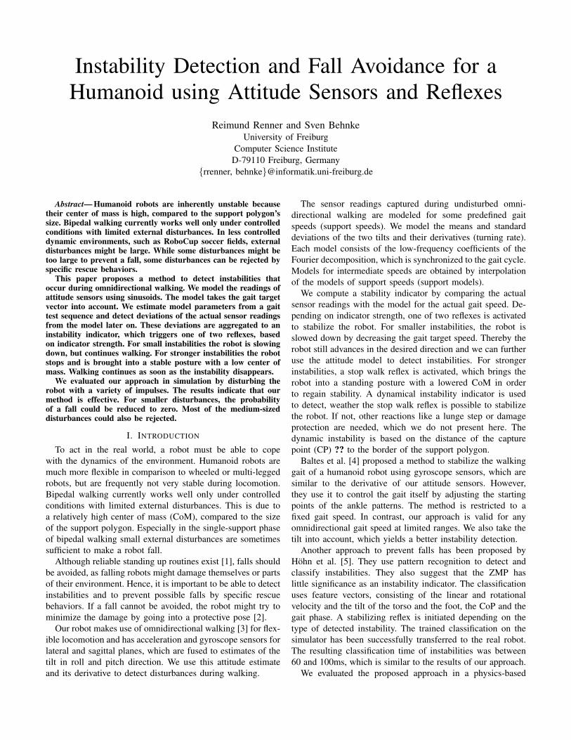
Fig. 1. KidSize robot Jupp of RoboCup Humanoid League team NimbRo.
Fig. 1 shows our humanoid robot Jupp, ready to kick theball. It and its twin Sepp have been constructed in our lab toparticipate in the RoboCupSoccer Humanoid League [11]. Inthe 2005 competition, which took place in Osaka, Japan, theyperformed very well. As KidSize team NimbRo they came insecond in the overall Best Humanoid ranking, next only to thetitleholder Team Osaka.
Jupp is driven by 19 servos: 6 in each leg, 3 in each arm,and one in the trunk. Its mechanical design focused on human-like proportions and light weight. The robot has a size of 60cmand a total weight of only 2.3kg.
Jupp is fully autonomous. It is powered by Lithium-polymerbatteries and equipped with a Pocket-PC and a wide-angle CF-camera. It has also two accelerometers and two gyros, whichare used to estimate the tilt of the robot. The Pocket PC runscomputer vision, behavior control, and communication. Usinga hierarchical framework for reactive behavior control, weimplemented omnidirectional walking [3], kicking, and basicsoccer skills.
The 2 vs. 2 soccer games at RoboCup 2005 led to consid-erable physical contact between the robots, as multiple robotswere going for the ball. Consequently, several falls occurredduring the final match, which was played between NimbRoand Team Osaka. While both teams had implemented reliablestanding-up routines for their robots [1], it would have beendesirable to detect and to reject disturbances. A video of thegame can be downloaded from http://www.NimbRo.net.
We used the attitude sensor of Jupp to detect a fall and toclassify the robot posture (prone or supine). This sensor is alsosuitable to detect instabilities that occur during omnidirectionalwalking, which are mostly caused by external disturbances.
The attitude sensor is located in the trunk of the robot. Itconsists of a dual-axis accelerometer (ADXL203, ±1.5g) andtwo gyroscopes (ADXRS 150/300, ±150/300 deg/s). The fouranalog sensor signals are digitized with A/D converters of theHCS12 and are preprocessed by the microcontroller.
On the Pocket PC, the readings of accelerometers andgyros are fused to estimate the robot’s tilt in roll and pitchdirection. For each axis, the gyro bias is calibrated, assumingthat over intervals of 2.4s the integrated bias-corrected gyrorates equal the difference between the tilts estimated from theaccelerometers. Here we assume that, in the long run, the ac-celerometers measure the decomposition of the gravity vector.Combining the low-frequency components of the tilt estimatedfrom accelerometers with the integrated bias-corrected gyrorates yields an estimate of the robot’s attitude that is insensitiveto short linear accelerations.
III. ATTITUDE MODEL
Because of the periodic nature of walking, a gait-cyclesynchronous Fourier transform seems to be appropriate tomodel the attitude estimates. We use only the low-frequencycoefficients of the transformed signals to keep the number ofparameters small. The omnidirectional walking is parameter-ized by the gait target vector (vx, vy, vθ), where vx, vy, vθ ∈[−1, 1] are the lateral, sagittal and rotational speed compo-nents, respectively. The speeds are normalized, such that vy=1represents the maximal speed in forward direction.
The model of one constant gait speed consists of the firstFourier coefficients C = (c0, c1, . . . , cM ) of the means µi
and standard deviations σi at the gait phase Θ ∈ [−π, π).i ∈ S = {ϕl, ϕl, ϕs, ϕs} enumerates the attitude sensors (ϕ)and their derivatives (ϕ) in the lateral (l) and sagittal (s) planes.
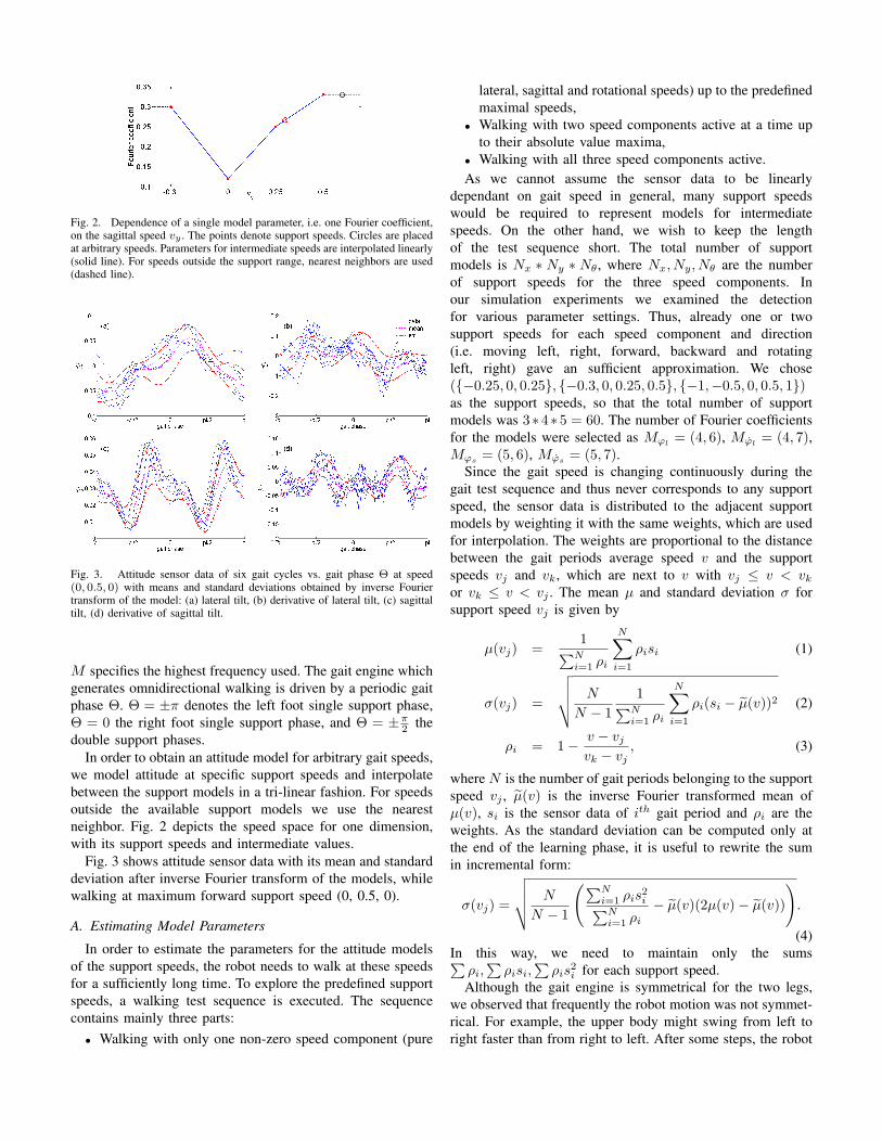
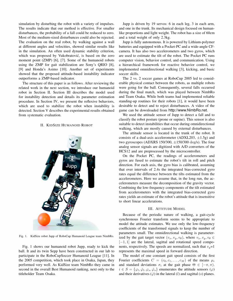
Fig. 2. Dependence of a single model parameter, i.e. one Fourier coefficient,on the sagittal speed vy . The points denote support speeds. Circles are placedat arbitrary speeds. Parameters for intermediate speeds are interpolated linearly(solid line). For speeds outside the support range, nearest neighbors are used(dashed line).
Fig. 3. Attitude sensor data of six gait cycles vs. gait phase Θ at speed(0, 0.5, 0) with means and standard deviations obtained by inverse Fouriertransform of the model: (a) lateral tilt, (b) derivative of lateral tilt, (c) sagittaltilt, (d) derivative of sagittal tilt.
M specifies the highest frequency used. The gait engine whichgenerates omnidirectional walking is driven by a periodic gaitphase Θ. Θ = ±π denotes the left foot single support phase,Θ = 0 the right foot single support phase, and Θ = ±π
2 thedouble support phases.
In order to obtain an attitude model for arbitrary gait speeds,we model attitude at specific support speeds and interpolatebetween the support models in a tri-linear fashion. For speedsoutside the available support models we use the nearestneighbor. Fig. 2 depicts the speed space for one dimension,with its support speeds and intermediate values.
Fig. 3 shows attitude sensor data with its mean and standarddeviation after inverse Fourier transform of the models, whilewalking at maximum forward support speed (0, 0.5, 0).
A. Estimating Model Parameters
In order to estimate the parameters for the attitude modelsof the support speeds, the robot needs to walk at these speedsfor a sufficiently long time. To explore the predefined supportspeeds, a walking test sequence is executed. The sequencecontains mainly three parts:
• Walking with only one non-zero speed component (pure
lateral, sagittal and rotational speeds) up to the predefinedmaximal speeds,
• Walking with two speed components active at a time upto their absolute value maxima,
• Walking with all three speed components active.As we cannot assume the sensor data to be linearly
dependant on gait speed in general, many support speedswould be required to represent models for intermediatespeeds. On the other hand, we wish to keep the lengthof the test sequence short. The total number of supportmodels is Nx ∗ Ny ∗ Nθ, where Nx, Ny, Nθ are the numberof support speeds for the three speed components. Inour simulation experiments we examined the detectionfor various parameter settings. Thus, already one or twosupport speeds for each speed component and direction(i.e. moving left, right, forward, backward and rotatingleft, right) gave an sufficient approximation. We chose({−0.25, 0, 0.25}, {−0.3, 0, 0.25, 0.5}, {−1,−0.5, 0, 0.5, 1})as the support speeds, so that the total number of supportmodels was 3∗4∗5 = 60. The number of Fourier coefficientsfor the models were selected as Mϕl
= (4, 6), Mϕl= (4, 7),
Mϕs = (5, 6), Mϕs = (5, 7).Since the gait speed is changing continuously during the
gait test sequence and thus never corresponds to any supportspeed, the sensor data is distributed to the adjacent supportmodels by weighting it with the same weights, which are usedfor interpolation. The weights are proportional to the distancebetween the gait periods average speed v and the supportspeeds vj and vk, which are next to v with vj ≤ v < vk
or vk ≤ v < vj . The mean µ and standard deviation σ forsupport speed vj is given by
µ(vj) =1∑N
i=1 ρi
N∑i=1
ρisi (1)
σ(vj) =
√√√√ N
N − 11∑N
i=1 ρi
N∑i=1
ρi(si − µ(v))2 (2)
ρi = 1− v − vj
vk − vj, (3)
where N is the number of gait periods belonging to the supportspeed vj , µ(v) is the inverse Fourier transformed mean ofµ(v), si is the sensor data of ith gait period and ρi are theweights. As the standard deviation can be computed only atthe end of the learning phase, it is useful to rewrite the sumin incremental form:
σ(vj) =
√√√√ N
N − 1
(∑Ni=1 ρis2
i∑Ni=1 ρi
− µ(v)(2µ(v)− µ(v))
).
(4)In this way, we need to maintain only the sums∑
ρi,∑
ρisi,∑
ρis2i for each support speed.
Although the gait engine is symmetrical for the two legs,we observed that frequently the robot motion was not symmet-rical. For example, the upper body might swing from left toright faster than from right to left. After some steps, the robot
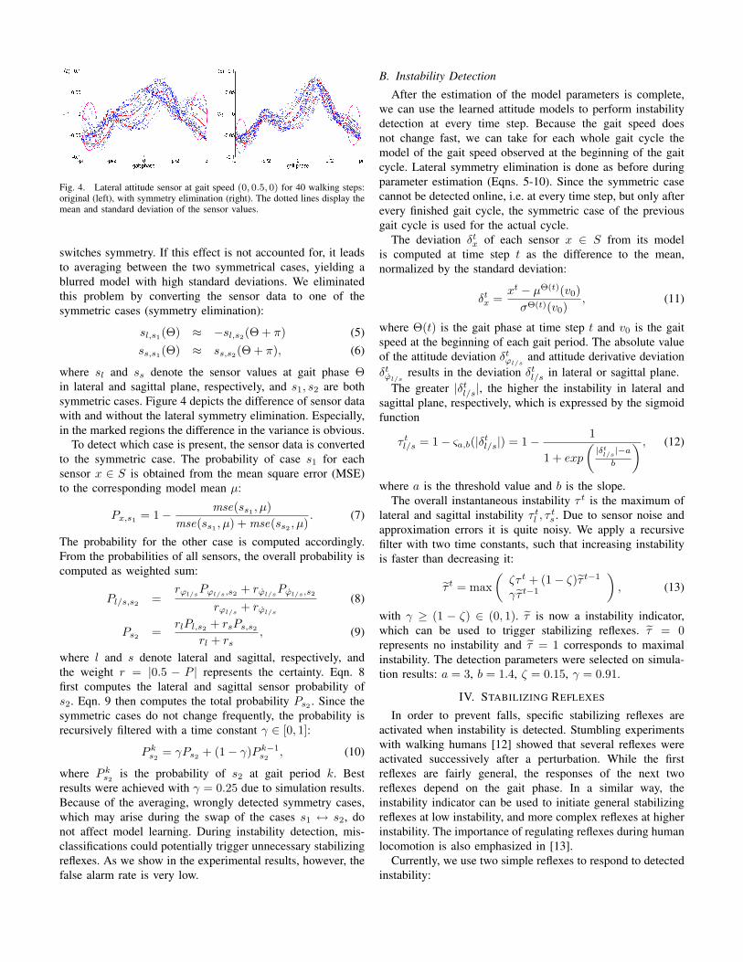
Fig. 4. Lateral attitude sensor at gait speed (0, 0.5, 0) for 40 walking steps:original (left), with symmetry elimination (right). The dotted lines display themean and standard deviation of the sensor values.
switches symmetry. If this effect is not accounted for, it leadsto averaging between the two symmetrical cases, yielding ablurred model with high standard deviations. We eliminatedthis problem by converting the sensor data to one of thesymmetric cases (symmetry elimination):
sl,s1(Θ) ≈ −sl,s2(Θ + π) (5)ss,s1(Θ) ≈ ss,s2(Θ + π), (6)
where sl and ss denote the sensor values at gait phase Θin lateral and sagittal plane, respectively, and s1, s2 are bothsymmetric cases. Figure 4 depicts the difference of sensor datawith and without the lateral symmetry elimination. Especially,in the marked regions the difference in the variance is obvious.
To detect which case is present, the sensor data is convertedto the symmetric case. The probability of case s1 for eachsensor x ∈ S is obtained from the mean square error (MSE)to the corresponding model mean µ:
Px,s1 = 1− mse(ss1 , µ)mse(ss1 , µ) + mse(ss2 , µ)
. (7)
The probability for the other case is computed accordingly.From the probabilities of all sensors, the overall probability iscomputed as weighted sum:
Pl/s,s2 =rϕl/s
Pϕl/s,s2 + rϕl/sPϕl/s,s2
rϕl/s+ rϕl/s
(8)
Ps2 =rlPl,s2 + rsPs,s2
rl + rs, (9)
where l and s denote lateral and sagittal, respectively, andthe weight r = |0.5 − P | represents the certainty. Eqn. 8first computes the lateral and sagittal sensor probability ofs2. Eqn. 9 then computes the total probability Ps2 . Since thesymmetric cases do not change frequently, the probability isrecursively filtered with a time constant γ ∈ [0, 1]:
P ks2
= γPs2 + (1− γ)P k−1s2
, (10)
where P ks2
is the probability of s2 at gait period k. Bestresults were achieved with γ = 0.25 due to simulation results.Because of the averaging, wrongly detected symmetry cases,which may arise during the swap of the cases s1 ↔ s2, donot affect model learning. During instability detection, mis-classifications could potentially trigger unnecessary stabilizingreflexes. As we show in the experimental results, however, thefalse alarm rate is very low.
B. Instability Detection
After the estimation of the model parameters is complete,we can use the learned attitude models to perform instabilitydetection at every time step. Because the gait speed doesnot change fast, we can take for each whole gait cycle themodel of the gait speed observed at the beginning of the gaitcycle. Lateral symmetry elimination is done as before duringparameter estimation (Eqns. 5-10). Since the symmetric casecannot be detected online, i.e. at every time step, but only afterevery finished gait cycle, the symmetric case of the previousgait cycle is used for the actual cycle.
The deviation δtx of each sensor x ∈ S from its model
is computed at time step t as the difference to the mean,normalized by the standard deviation:
δtx =
xt − µΘ(t)(v0)σΘ(t)(v0)
, (11)
where Θ(t) is the gait phase at time step t and v0 is the gaitspeed at the beginning of each gait period. The absolute valueof the attitude deviation δt
ϕl/sand attitude derivative deviation
δtϕl/s
results in the deviation δtl/s in lateral or sagittal plane.
The greater |δtl/s|, the higher the instability in lateral and
sagittal plane, respectively, which is expressed by the sigmoidfunction
τ tl/s = 1− ςa,b(|δt
l/s|) = 1− 1
1 + exp
(|δt
l/s|−a
b
) , (12)
where a is the threshold value and b is the slope.The overall instantaneous instability τ t is the maximum of
lateral and sagittal instability τ tl , τ
ts . Due to sensor noise and
approximation errors it is quite noisy. We apply a recursivefilter with two time constants, such that increasing instabilityis faster than decreasing it:
τ t = max(
ζτ t + (1− ζ)τ t−1
γτ t−1
), (13)
with γ ≥ (1 − ζ) ∈ (0, 1). τ is now a instability indicator,which can be used to trigger stabilizing reflexes. τ = 0represents no instability and τ = 1 corresponds to maximalinstability. The detection parameters were selected on simula-tion results: a = 3, b = 1.4, ζ = 0.15, γ = 0.91.
IV. STABILIZING REFLEXES
In order to prevent falls, specific stabilizing reflexes areactivated when instability is detected. Stumbling experimentswith walking humans [12] showed that several reflexes wereactivated successively after a perturbation. While the firstreflexes are fairly general, the responses of the next tworeflexes depend on the gait phase. In a similar way, theinstability indicator can be used to initiate general stabilizingreflexes at low instability, and more complex reflexes at higherinstability. The importance of regulating reflexes during humanlocomotion is also emphasized in [13].
Currently, we use two simple reflexes to respond to detectedinstability:
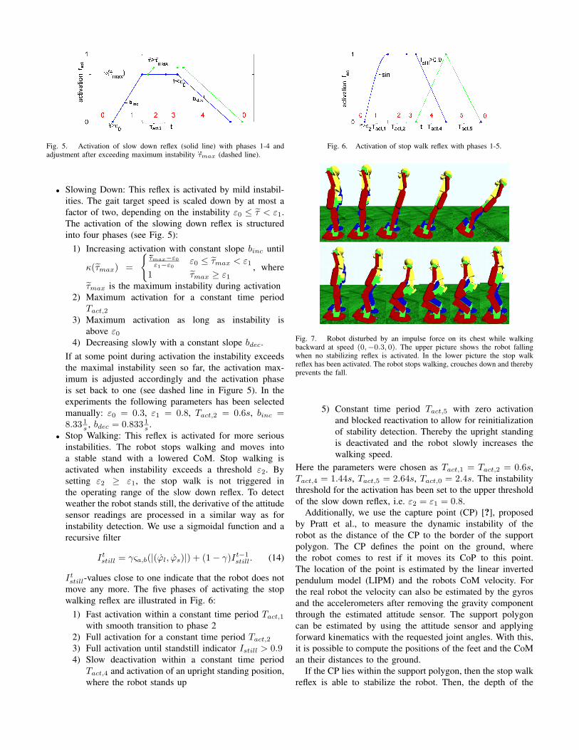
Fig. 5. Activation of slow down reflex (solid line) with phases 1-4 andadjustment after exceeding maximum instability eτmax (dashed line).
• Slowing Down: This reflex is activated by mild instabil-ities. The gait target speed is scaled down by at most afactor of two, depending on the instability ε0 ≤ τ < ε1.The activation of the slowing down reflex is structuredinto four phases (see Fig. 5):
1) Increasing activation with constant slope binc until
κ(τmax) =
{eτmax−ε0
ε1−ε0ε0 ≤ τmax < ε1
1 τmax ≥ ε1
, where
τmax is the maximum instability during activation2) Maximum activation for a constant time period
Tact,2
3) Maximum activation as long as instability isabove ε0
4) Decreasing slowly with a constant slope bdec.If at some point during activation the instability exceedsthe maximal instability seen so far, the activation max-imum is adjusted accordingly and the activation phaseis set back to one (see dashed line in Figure 5). In theexperiments the following parameters has been selectedmanually: ε0 = 0.3, ε1 = 0.8, Tact,2 = 0.6s, binc =8.33 1
s , bdec = 0.833 1s .
• Stop Walking: This reflex is activated for more seriousinstabilities. The robot stops walking and moves intoa stable stand with a lowered CoM. Stop walking isactivated when instability exceeds a threshold ε2. Bysetting ε2 ≥ ε1, the stop walk is not triggered inthe operating range of the slow down reflex. To detectweather the robot stands still, the derivative of the attitudesensor readings are processed in a similar way as forinstability detection. We use a sigmoidal function and arecursive filter
Itstill = γςa,b(|(ϕl, ϕs)|) + (1− γ)It−1
still. (14)
Itstill-values close to one indicate that the robot does not
move any more. The five phases of activating the stopwalking reflex are illustrated in Fig. 6:
1) Fast activation within a constant time period Tact,1
with smooth transition to phase 22) Full activation for a constant time period Tact,2
3) Full activation until standstill indicator Istill > 0.94) Slow deactivation within a constant time period
Tact,4 and activation of an upright standing position,where the robot stands up
Fig. 6. Activation of stop walk reflex with phases 1-5.
Fig. 7. Robot disturbed by an impulse force on its chest while walkingbackward at speed (0,−0.3, 0). The upper picture shows the robot fallingwhen no stabilizing reflex is activated. In the lower picture the stop walkreflex has been activated. The robot stops walking, crouches down and therebyprevents the fall.
5) Constant time period Tact,5 with zero activationand blocked reactivation to allow for reinitializationof stability detection. Thereby the upright standingis deactivated and the robot slowly increases thewalking speed.
Here the parameters were chosen as Tact,1 = Tact,2 = 0.6s,Tact,4 = 1.44s, Tact,5 = 2.64s, Tact,0 = 2.4s. The instabilitythreshold for the activation has been set to the upper thresholdof the slow down reflex, i.e. ε2 = ε1 = 0.8.
Additionally, we use the capture point (CP) [?], proposedby Pratt et al., to measure the dynamic instability of therobot as the distance of the CP to the border of the supportpolygon. The CP defines the point on the ground, wherethe robot comes to rest if it moves its CoP to this point.The location of the point is estimated by the linear invertedpendulum model (LIPM) and the robots CoM velocity. Forthe real robot the velocity can also be estimated by the gyrosand the accelerometers after removing the gravity componentthrough the estimated attitude sensor. The support polygoncan be estimated by using the attitude sensor and applyingforward kinematics with the requested joint angles. With this,it is possible to compute the positions of the feet and the CoMan their distances to the ground.
If the CP lies within the support polygon, then the stop walkreflex is able to stabilize the robot. Then, the depth of the
crouching during the stop walk reflex can be set proportionalto the dynamic stability. Otherwise, if the CP lies outside thesuport polygon, other kind of reactions, like a lunge step, areneeded. Or if the CP is too far, no fall avoidance is possible,and we need to make damage protecting reactions. However,this is not part of this work.
Another stopping method was proposed by Morisawaet al. [14]. When being in the single support phase, therobot first makes a final step to obtain double support. Thenmovements are computed to slow down the robot, based onapproximated mathematical models using the CoM and theZMP. The CoM is also lowered to increase stability. In ourcase, the double support is achieved by the continuouslyincreasing activation of the stopping reflex. This moves therobot smoothly into a stable standing posture. Fig. 7 shows therobot after an impulse disturbance while walking. The robotfalls when no stabilizing reflexes are activated, but stabilizeswhen they are.
V. EXPERIMENTAL RESULTS
To evaluate our fall detection and fall avoidance approach,we disturbed the robot during walking in the ODE-basedsimulator with a variety of impulse forces. The impulses areproduced by a constant force, which acts for a single time steponto the robot.
We first compared the attitude sensor based instability withan instability indicator that is based on the ZMP criterion. Fallstatistics have been made to show that the instability detectionis effective for activating stabilizing responses.
As already mentioned in the first section, the ZMP can beused as a dynamic stability criterion so that a comparison ismeaningful. To do this, an instability indicator is computedin the same way as for the attitude readings (Eqns. 12-13).We use the distance of the ZMP to the closest edge ofthe support polygon as input and tested parameters for thesigmoid and the recursive filter. We compare the forewarntime with the false alarm rate. The forewarn time is the timebetween the first rise of the instability above a threshold of0.5 and the time when the attitude angle of the robot deviatesmore than 25◦ from the upright posture. The false alarmrate is the percentage of instability detections (>0.5) duringundisturbed, stable gait. Both are averaged over varying gaitspeeds (forward, backward, left, turn left at different speeds),forces (6, 9, 12), force directions (trunk front, rear, left, right;left upper arm front, rear), and five disturbance time points(relative to gait phase). As the forewarn time and the falsealarm rate are dependant on each other, the instability iscomputed for varying sigmoid and recursive filter parameters.Since the robot hardly gets onto the whole planar sole of afoot during walking in the simulator, the support polygon isdefined as the part of the sole of a foot with a distance smallerthan 1cm to the ground.
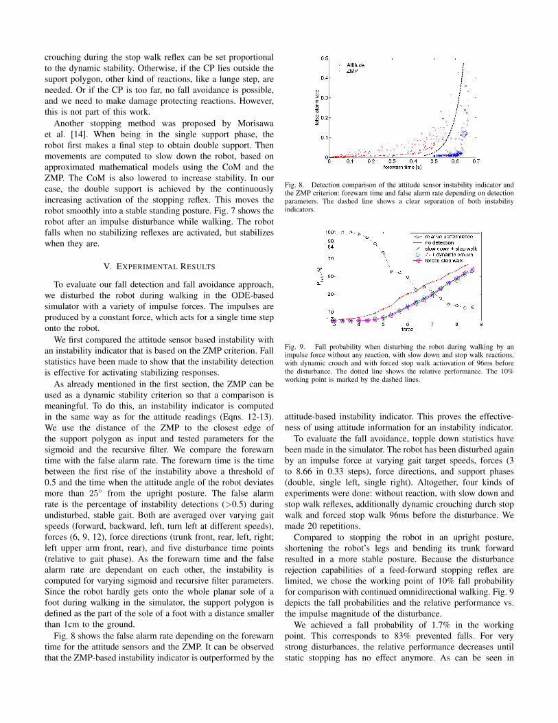
Fig. 8 shows the false alarm rate depending on the forewarntime for the attitude sensors and the ZMP. It can be observedthat the ZMP-based instability indicator is outperformed by the
Fig. 8. Detection comparison of the attitude sensor instability indicator andthe ZMP criterion: forewarn time and false alarm rate depending on detectionparameters. The dashed line shows a clear separation of both instabilityindicators.
Fig. 9. Fall probability when disturbing the robot during walking by animpulse force without any reaction, with slow down and stop walk reactions,with dynamic crouch and with forced stop walk actiovation of 96ms beforethe disturbance. The dotted line shows the relative performance. The 10%working point is marked by the dashed lines.
attitude-based instability indicator. This proves the effective-ness of using attitude information for an instability indicator.
To evaluate the fall avoidance, topple down statistics havebeen made in the simulator. The robot has been disturbed againby an impulse force at varying gait target speeds, forces (3to 8.66 in 0.33 steps), force directions, and support phases(double, single left, single right). Altogether, four kinds ofexperiments were done: without reaction, with slow down andstop walk reflexes, additionally dynamic crouching durch stopwalk and forced stop walk 96ms before the disturbance. Wemade 20 repetitions.
Compared to stopping the robot in an upright posture,shortening the robot’s legs and bending its trunk forwardresulted in a more stable posture. Because the disturbancerejection capabilities of a feed-forward stopping reflex arelimited, we chose the working point of 10% fall probabilityfor comparison with continued omnidirectional walking. Fig. 9depicts the fall probabilities and the relative performance vs.the impulse magnitude of the disturbance.
We achieved a fall probability of 1.7% in the workingpoint. This corresponds to 83% prevented falls. For verystrong disturbances, the relative performance decreases untilstatic stopping has no effect anymore. As can be seen in
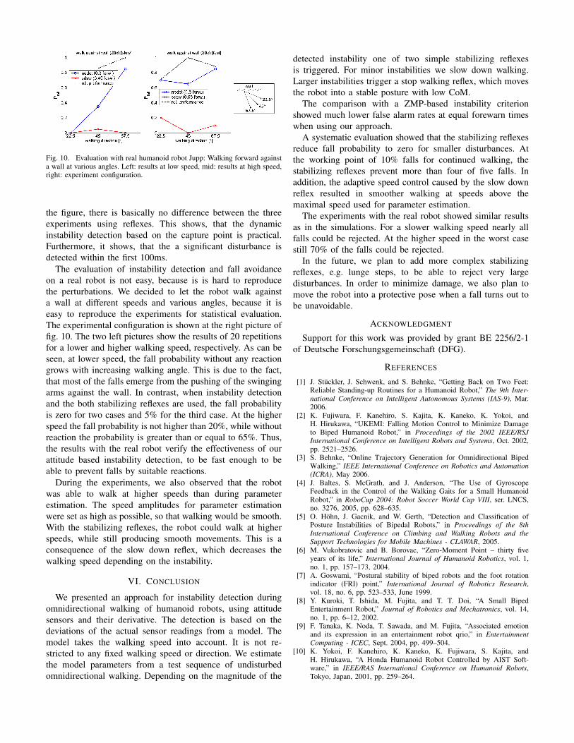
Fig. 10. Evaluation with real humanoid robot Jupp: Walking forward againsta wall at various angles. Left: results at low speed, mid: results at high speed,right: experiment configuration.
the figure, there is basically no difference between the threeexperiments using reflexes. This shows, that the dynamicinstability detection based on the capture point is practical.Furthermore, it shows, that the a significant disturbance isdetected within the first 100ms.
The evaluation of instability detection and fall avoidanceon a real robot is not easy, because is is hard to reproducethe perturbations. We decided to let the robot walk againsta wall at different speeds and various angles, because it iseasy to reproduce the experiments for statistical evaluation.The experimental configuration is shown at the right picture offig. 10. The two left pictures show the results of 20 repetitionsfor a lower and higher walking speed, respectively. As can beseen, at lower speed, the fall probability without any reactiongrows with increasing walking angle. This is due to the fact,that most of the falls emerge from the pushing of the swingingarms against the wall. In contrast, when instability detectionand the both stabilizing reflexes are used, the fall probabilityis zero for two cases and 5% for the third case. At the higherspeed the fall probability is not higher than 20%, while withoutreaction the probability is greater than or equal to 65%. Thus,the results with the real robot verify the effectiveness of ourattitude based instability detection, to be fast enough to beable to prevent falls by suitable reactions.
During the experiments, we also observed that the robotwas able to walk at higher speeds than during parameterestimation. The speed amplitudes for parameter estimationwere set as high as possible, so that walking would be smooth.With the stabilizing reflexes, the robot could walk at higherspeeds, while still producing smooth movements. This is aconsequence of the slow down reflex, which decreases thewalking speed depending on the instability.
VI. CONCLUSION
We presented an approach for instability detection duringomnidirectional walking of humanoid robots, using attitudesensors and their derivative. The detection is based on thedeviations of the actual sensor readings from a model. Themodel takes the walking speed into account. It is not re-stricted to any fixed walking speed or direction. We estimatethe model parameters from a test sequence of undisturbedomnidirectional walking. Depending on the magnitude of the
detected instability one of two simple stabilizing reflexesis triggered. For minor instabilities we slow down walking.Larger instabilities trigger a stop walking reflex, which movesthe robot into a stable posture with low CoM.
The comparison with a ZMP-based instability criterionshowed much lower false alarm rates at equal forewarn timeswhen using our approach.
A systematic evaluation showed that the stabilizing reflexesreduce fall probability to zero for smaller disturbances. Atthe working point of 10% falls for continued walking, thestabilizing reflexes prevent more than four of five falls. Inaddition, the adaptive speed control caused by the slow downreflex resulted in smoother walking at speeds above themaximal speed used for parameter estimation.
The experiments with the real robot showed similar resultsas in the simulations. For a slower walking speed nearly allfalls could be rejected. At the higher speed in the worst casestill 70% of the falls could be rejected.
In the future, we plan to add more complex stabilizingreflexes, e.g. lunge steps, to be able to reject very largedisturbances. In order to minimize damage, we also plan tomove the robot into a protective pose when a fall turns out tobe unavoidable.
ACKNOWLEDGMENT
Support for this work was provided by grant BE 2256/2-1of Deutsche Forschungsgemeinschaft (DFG).
REFERENCES
[1] J. Stuckler, J. Schwenk, and S. Behnke, “Getting Back on Two Feet:Reliable Standing-up Routines for a Humanoid Robot,” The 9th Inter-national Conference on Intelligent Autonomous Systems (IAS-9), Mar.2006.
[2] K. Fujiwara, F. Kanehiro, S. Kajita, K. Kaneko, K. Yokoi, andH. Hirukawa, “UKEMI: Falling Motion Control to Minimize Damageto Biped Humanoid Robot,” in Proceedings of the 2002 IEEE/RSJInternational Conference on Intelligent Robots and Systems, Oct. 2002,pp. 2521–2526.
[3] S. Behnke, “Online Trajectory Generation for Omnidirectional BipedWalking,” IEEE International Conference on Robotics and Automation(ICRA), May 2006.
[4] J. Baltes, S. McGrath, and J. Anderson, “The Use of GyroscopeFeedback in the Control of the Walking Gaits for a Small HumanoidRobot,” in RoboCup 2004: Robot Soccer World Cup VIII, ser. LNCS,no. 3276, 2005, pp. 628–635.
[5] O. Hohn, J. Gacnik, and W. Gerth, “Detection and Classification ofPosture Instabilities of Bipedal Robots,” in Proceedings of the 8thInternational Conference on Climbing and Walking Robots and theSupport Technologies for Mobile Machines - CLAWAR, 2005.
[6] M. Vukobratovic and B. Borovac, “Zero-Moment Point – thirty fiveyears of its life,” International Journal of Humanoid Robotics, vol. 1,no. 1, pp. 157–173, 2004.
[7] A. Goswami, “Postural stability of biped robots and the foot rotationindicator (FRI) point,” International Journal of Robotics Research,vol. 18, no. 6, pp. 523–533, June 1999.
[8] Y. Kuroki, T. Ishida, M. Fujita, and T. T. Doi, “A Small BipedEntertainment Robot,” Journal of Robotics and Mechatronics, vol. 14,no. 1, pp. 6–12, 2002.
[9] F. Tanaka, K. Noda, T. Sawada, and M. Fujita, “Associated emotionand its expression in an entertainment robot qrio,” in EntertainmentComputing - ICEC, Sept. 2004, pp. 499–504.
[10] K. Yokoi, F. Kanehiro, K. Kaneko, K. Fujiwara, S. Kajita, andH. Hirukawa, “A Honda Humanoid Robot Controlled by AIST Soft-ware,” in IEEE/RAS International Conference on Humanoid Robots,Tokyo, Japan, 2001, pp. 259–264.
[11] S. Behnke, “Playing Soccer with Humanoid Robots,” KI – ZeitschriftKunstliche Intelligenz, 2006.
[12] A. M. Schillings, B. M. H. V. Wezel, T. Mulder, and J. Duysens,“Muscular Responses and Movement Strategies during Stumbling overObstacles,” Journal of Neurophysiology, no. 83, pp. 2093–2102, 2000.
[13] P. Zehr and B. Stein, “What functions do reflexes serve during humanlocomotion?” Prog Neurobiol., vol. 58, no. 2, pp. 185–205, June 1999.
[14] M. Morisawa, S. Kajita, K. Harada, K. Fujiwara, K. K. Fumio Kanehiro,and H. Hirukawa, “Emergency Stop Algorithm for Walking HumanoidRobots,” IEEE/RSJ International Conference on Intelligent Robots andSystems, 2005.