Embed Size (px)
Citation preview

Part
No: 1
0026
47 -
NOV2
020
Installation & Maintenance InstructionsSingle & Twin Coil Unvented Cylinders
90/120/150/180/210/250/300 litre
Green Storage Cylinders
2
Green Storage WB RangeInstallation & Maintenance Instructions
WORCESTER BOSCH CONTACT INFORMATION
TECHNICAL SUPPORT: 0330 123 3366CONTROLS & CONNECTIVITY TEAM: 0330 123 3641APPOINTMENTS: 0330 123 9339SPARES: 0330 123 9779LITERATURE: 0330 123 9119TRAINING: 0330 123 0166SALES: 0330 123 9669
We are a Charter Members of the Hot Water Association and undertake to meet the requirements of the Charter Scheme: To supply fit for purpose products clearly and honestly described. To supply products that meet or exceed appropriate standards and building and water regulations. To provide pre- and post-technical support.
To provide a clear and concise warranty details to customers. For further details on the Charter, please visit www.hotwater.org.uk/hwa-charter
INTRODUCTION
These cylinders are manufactured to the highest specification standards with superior product engineering, materials and stringent production processes, to deliver the highest quality products.
When installed and maintained in accordance with this manual, the cylinders will reliably store and generate hot water for years to come. The manual details how to prepare, install, commission, service and decommission the cylinders. It covers both indirect and solar models with an external thermal expansion vessel. A separate insert sheet contains specific technical details for your chosen hot water cylinder.
As well as comprehensive instructions for installers, the manual provides guidance and guarantee information for homeowners.
Benchmark places responsibilities on both the manufacturer and installer. The purpose is to ensure that customers are provided with the correct equipment for their needs, that the equipment is installed, commissioned and serviced in accordance with the manufacturer’s instructions by competent persons and that it meets the requirements of the appropriate Building Regulations. The Benchmark Checklist can be used to demonstrate compliance with Building Regulations and should be provided to the customer for future reference.
Installers are required to carry out installation, commissioning and servicing work in accordance with the Benchmark Code of Practice which is available from the Heating and Hotwater Industry Council who manage and promote the Scheme. Visit www.centralheating.co.uk for more information.
THE BENCHMARK CODE DEMONSTRATING COMPLIANCE, REASSURING HOMEOWNERS
CONTENTS
3 Your cylinder and its components3 Preparing to install the cylinder4 - 7 Installation instructions8 Product specification details9 Product diagrams, connections & measurements10 - 11 Fiche Data & Parts List12 - 13 Fitting with Greenstar system boilers with optional internal
diverter valves13 - 17 Schematic wiring diagrams18 Commissioning and decommissioning19 Servicing instructions and fault-finding20 Information for homeowners21 Benchmark Commissioning Checklist22 Service record23 - 24 Guarantee and product registration
IMPORTANT NOTE TO THE INSTALLER
Read these instructions before commencing installation. Unvented cylinders are a controlled service as defined in the latest edition of the building regulations and should only be fitted by a competent person.You must ensure the installation complies with the current Building Regulations and or Technical Standards Documents for England, Scotland, Wales, N Ireland or Ireland.
After installation the Benchmark Commissioning Checklist on page 21 must be completed and left, with these instructions, with the householder for future reference.
IMPORTANT NOTE TO THE HOMEOWNER
Please ensure that the installer has fully completed the Benchmark Commissioning Checklist on page 21 of this installation manual. You will need this information should you need to make a claim against your product guarantee in the future.
This product requires servicing every 12 months and the Service Record must be maintained to protect your 25-year guarantee.
Please note all images are for illustrative purposes only and specific products will vary for each product line.

3
Green Storage WB RangeInstallation & Maintenance Instructions
YOUR CYLINDER AND ITS COMPONENTSThe unvented cylinder comes complete with the necessary fittings, safety and control devices needed to connect to the cold water mains. All have been pre-adjusted. High quality controls have been selected to combine high flow rate performance with minimum pressure drop to make the unvented cylinder perform well in all areas, even those with poor water pressure. See insert sheet for a list of spare parts.
SUPPLIED COMPONENTSAll indirect models are supplied with installation and maintenance instructions, technical performance & specification data fiche, an inlet control set, a temperature and pressure relief valve, an acetal tundish and an external expansion vessel, immersion heater, dual Thermostat, two-port motorised valve. In addition to the above twin coil / solar indirect models also include a single high limit thermostat and a sensor pocket retaining bung. Note: If the water quality is aggressive, we recommend exchanging the immersion heater for a titanium element.
ELECTRICITY SUPPLYThe unvented cylinder requires 230V 50Hz electrical supply for the immersion elements. The electrical supply to each immersion heater must be fused at 13A via a double pole isolating switch that meets the current BS Standards. The cable must be at least 2.5mm2 heat resistant (85°C HOFR) sheathed flex complying to the current BS Standards.
SITING THE UNIT The unvented cylinder can supply outlets above it or at some distance from it. Site the unit to minimise “dead leg” distances, especially to the point of most frequent use. Outlets above the unvented cylinder will reduce the outlet pressure available by 0.1 bar for every 1m of height difference. The unit should be protected from frost. Particular care is needed if siting in a garage, outbuilding or loft space. All exposed pipework should be insulated. The unvented cylinder must be installed in the correct orientation i.e. vertically, on a flat base capable of supporting the weight of the cylinder when full. See technical specification insert sheet for weights. The minimum recommended cupboard size for vertical models is 750mm square.
Access Consideration should be given to the position of discharge pipework (tundish) and drain valves. Avoid positioning these too close to electrical devices and components. Also allow sufficient space so that the cylinder can be inspected, maintained and serviced in the future.
The immersion heaters are 400mm long and care should be taken to ensure that they can be withdrawn, enabling the immersion heater to be replaced at the end of its working life and providing inspection access to the interior of the cylinder during servicing if required.
The discharge pipework from the safety valves should fall continuously and terminate safely.
STORAGE PRIOR TO INSTALLATIONThe unvented cylinder should be stored in its original packaging in an upright position in an area free from excessive moisture.
HANDLING PRODUCTThe unvented cylinder should be carried upright where possible. Assessments of risks for carrying the cylinder should be conducted. Use more than one person for carrying where appropriate. Always follow latest guidelines for lifting techniques, to avoid injury, or damage to the product.
WATER SUPPLYThe unvented cylinder operates at 3 bar (controlled by the inlet control set) and is capable of delivering over 50 litres per minute. The high quality inlet control set has been designed to make the most of the flow rates available, however the performance of any unvented system is only as good as the mains water supply. The maximum possible water demand should be assessed, taking into consideration that both hot and cold services are supplied simultaneously from the mains.
The water supply should be checked to ensure it can meet these requirements. If necessary, consult the local water company regarding the likely pressure and flow rate availability.
If measuring the water pressure, note that a high static (no flow) mains pressure is no guarantee of good flow availability. In a domestic installation 1.5 bar and 25 l/min. should be regarded as the minimum. The maximum mains pressure that the inlet control set can accept is 12 bar.
Consideration should be given to upgrading existing 1/2” (15mm) cold mains pipework to a larger size if the recommended minimum pressure/flow rate is not being achieved.
YOUR CYLINDER AND ITS COMPONENTS
PREPARING TO INSTALL THE CYLINDER
4
Green Storage WB RangeInstallation & Maintenance Instructions
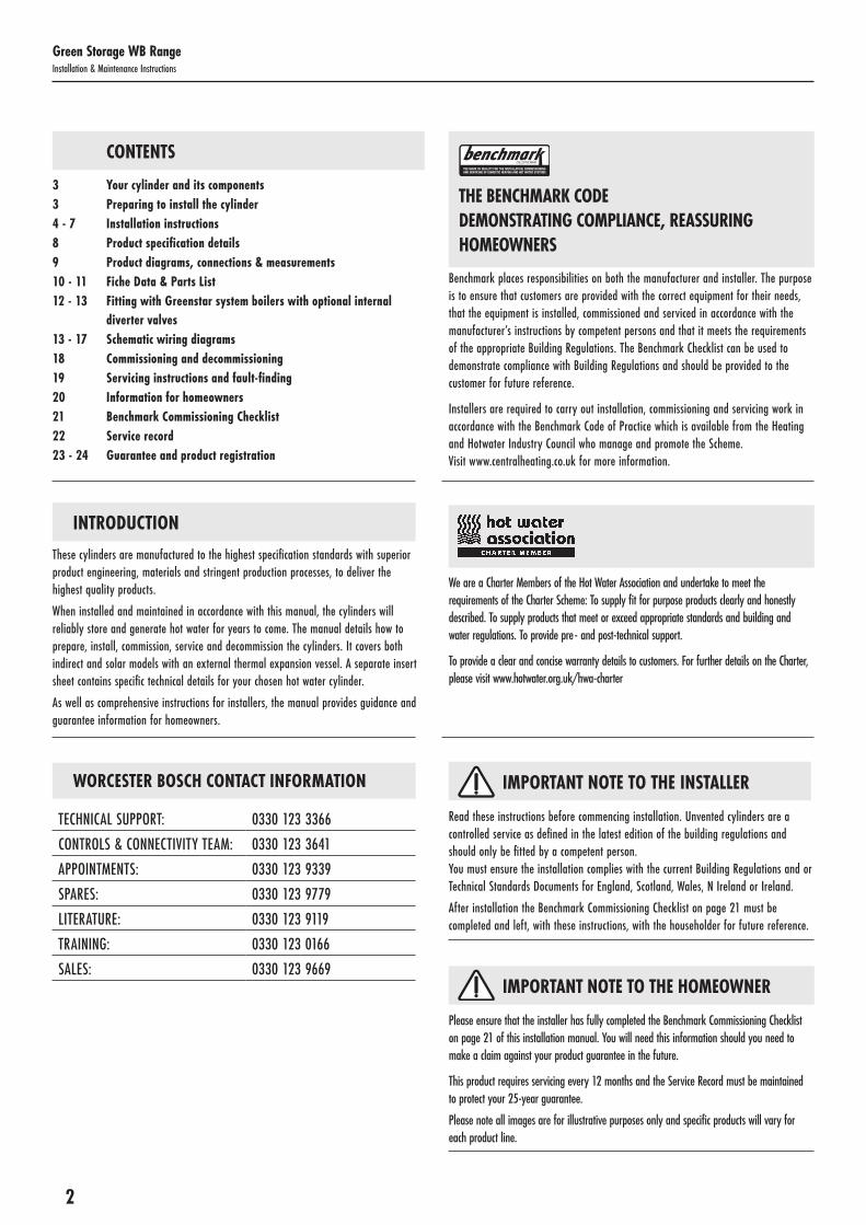
Notes: The pressure reducing valve, non-return valve and expansion relief valve are combined together in the inlet control set.
On 120 – 180 litre sizes there is no dedicated secondary return boss and the secondary return circuit should be tee’d into the cold feed pipe just above the drain elbow.
IMMERSIONHEATER
COLDMAIN
ISOLATINGVALVE
PRESSUREREDUCINGVALVE
NON RETURN
VALVE
EXPANSIONRELIEFVALVE
TUNDISH
TEMPERATURE& PRESSURERELIEF VALVE
BALANCEDCOLD CONNECTION
COLDINLET VIADRAIN
NON RETURNVALVE
BRONZEPUMP
SECONDARY RETURN CIRCUIT( 210, 250 & 300 L SIZES )
DUALSTAT2 PORT
VALVE
BOILERFLOW
BOILERRETURN
HOT OUTLET
EXPANSIONVESSELWITH WALL BRACKET
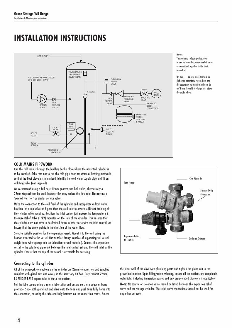
COLD MAINS PIPEWORK Run the cold mains through the building to the place where the unvented cylinder is to be installed. Take care not to run the cold pipe near hot water or heating pipework so that the heat pick-up is minimised. Identify the cold water supply pipe and fit an isolating valve (not supplied).
We recommend using a full bore 22mm quarter turn ball valve, alternatively a 22mm stopcock can be used, however this may reduce the flow rate. Do not use a “screwdriver slot” or similar service valve.
Make the connection to the cold feed of the cylinder and incorporate a drain valve. Position the drain valve no higher than the cold inlet to ensure sufficient draining of the cylinder when required. Position the inlet control just above the Temperature & Pressure Relief Valve (TPRV) mounted on the side of the cylinder. This ensures that the cylinder does not have to be drained down in order to service the inlet control set. Ensure that the arrow points in the direction of the water flow.
Select a suitable position for the expansion vessel. Mount it to the wall using the bracket attached to the vessel. Use suitable fittings capable of supporting full vessel weight (and with appropriate consideration to wall material). Connect the expansion vessel to the cold feed pipework between the inlet control set and the cold inlet on the cylinder. Ensure that the top of the vessel is accessible for servicing.
Connecting to the cylinderAll of the pipework connections on the cylinder are 22mm compression and supplied complete with gland nuts and olives, in the Accessory Kit box. Only connect 22mm BS EN1057-R250 copper tube to these connections.
Cut the tube square using a rotary tube cutter and ensure no sharp edges or burrs protrude. Slide both gland nut and olive onto the tube and push tube fully home into the connection, ensuring the tube end fully bottoms on the connection recess. Smear
the outer wall of the olive with plumbing paste and tighten the gland nut in the prescribed manner. Upon filling/commissioning, ensure all connections are completely watertight, including immersion bosses and any pre-plumbed pipework if applicable.
Note: No control or isolation valve should be fitted between the expansion relief valve and the storage cylinder. The relief valve connections should not be used for any other purpose.
Turn to testCold Mains In
Expansion Relief to Tundish
Balanced Cold Connection
Outlet to Cylinder
INSTALLATION INSTRUCTIONS

5
Green Storage WB RangeInstallation & Maintenance Instructions
BALANCED HOT & COLD SUPPLYThe installer must safeguard the hot water system from back flow by ensuring the hot and cold supply to all outlet locations are balanced. All mixer: taps, showers or valve shall be installed to comply with the Water Supply (Water Fittings) Regulations 1999. If these devices have un-balanced supplies there must be single check valves installed at both inlets, to stop over-pressurisation of either supply. Note the inlet control set provided with this cylinder features a balanced cold connection, to facilitate the installation of balanced supply.
HOT WATER PIPEWORK Run the first part of the hot water distribution pipework in 22mm. This can be reduced near to the outlet to 15mm or 10mm if appropriate, for example to suit the type of tap. You should aim to keep the run length of any hot water pipework from the cylinder to outlet to a practical minimum so the time taken for the hot water to reach the outlet is as quick as possible. Then connect the hot water pipework to the hot water draw-off on the cylinder (Position B in the diagrams on pages 9).
CONNECTIONS FOR INDIRECT UNITS For Solar input models refer to the shaded box before making any connections.Connect the primary connections using the compression connections provided. The primary circuit must be positively pumped. Gravity circulation is not suitable. Either primary connection may be used as the primary flow, reheat times are not affected. The primary circuit can be open vented or sealed, up to a maximum pressure of 3.5 bar. If you seal the primary circuit an additional expansion vessel and safety valve is required.Connect the two port valve into the primary flow pipework. The direction of the flow arrow should be towards the primary flow connection.Where connecting to a boiler, the boiler can be Gas, Electric or Oil, but must be under effective thermostatic control. Uncontrolled heat sources such as some AGAs, back boilers, solid fuel stoves, etc. are not suitable. Please contact our Technical department for guidance. Consult the boiler manufacturer’s instructions to confirm sizing is suitable for the heating system and guidance on positioning.
INSTALLATION INSTRUCTIONS (CONTINUED)
SOLAR INDIRECT UNVENTED (TWIN COIL)
Upper coil The upper coil is connected to the fossil fuel boiler as per the instructions for the unvented indirect single coil model, with the dual stat control and high limit thermostat inserted into pocket G2 (boiler). The wiring requirements are shown on page 13/17
Lower coil: solar installation The flow and return from the solar heat source are to be connected to the bottom coil. Either primary coil connection may be utilised as the flow or return. The solar primary circuit must have its own dedicated circulating pump, thermal and safety controls, which must be installed as per the solar manufacturer’s instructions. The solar control system used must be of the solar differential control type and should be connected to the solar sensor.
The solar sensor, supplied as part of the solar controls should be inserted into Pocket G1 (boiler) and is held in-situ with the black sensor pocket retaining bung provided.
It is necessary to connect the solar pump via the overtemperature high limit cut-out (provided) to ensure the heat input to the solar coil is interrupted if the cylinder overheats. Some method to prevent thermosyphoning must also be employed. Non-return check valves in the primary flow and return pipework would be acceptable. If solar controls do not offer appropriate isolation, a two port zone valve (not supplied) can be used with the pump and high limit stat as shown on page 14/15.
Note:
If it is intended to fit a cylinder with a solar coil to be used at a later date, the two coils should be connected in series to make use of the solar coil, using the dual stat in Pocket G2 (solar) or Pocket G1 (Solar), as shown in the diagram on page 9.
The Domestic Heating Compliance Guide document L1A and L1B provides excellent advice in sizing both cylinder dedicated solar areas and heat exchangers to the surface area of the solar collectors. Using this guide we are able to offer sizing advice for specification.
Note:
Consult all details of the compliance guide documentation prior to specifying product or commencing design.

6
Green Storage WB RangeInstallation & Maintenance Instructions
INSTALLATION INSTRUCTIONS (CONTINUED)
SECONDARY CIRCULATION CONNECTION This can be used with secondary circulation. An appropriate WRAS approved bronze or stainless steel circulator should be used in conjunction with a non-return valve to prevent backflow.
On large secondary circulation systems it may be necessary to incorporate an extra expansion vessel into the circuit to accommodate the increased system water volume.
A secondary return boss is fitted as standard on 210, 250 & 300 ltr units. On smaller sizes, use a swept tee to connect into the cold feed pipe above the drain.
IMMERSION HEATERS Only immersion heaters with a thermal cut-out that comply with BS EN 60335-2-73 may be used. To help ensure this, the immersion heaters have a special 13/4” thread. They are rated at 3kW at 240V and are of a low noise incoloy construction.
They have both a thermostat and a high limit cut-out. Please order the correct replacement via ourselves; fitting non-approved immersions may affect your guarantee. When fitting, ensure the ‘O’ ring is positioned correctly on the head of the immersion heater and lubricate before fitting. Fit it by hand until almost home then tighten gently, as the ‘O’ rings will seal easily. Electrical supply refer to page 3.
Do not operate the immersion heater/s until the cylinder is full of water.
Do not operate the immersion heater/s if any sterilisation liquid is in the cylinder as this will cause premature failure.
If the water quality is aggressive we recommend exchanging the immersion heater for a titanium element.
Note: Immersion heaters should never be used as the primary heat source.
ELECTRICAL CONNECTIONS Complete the wiring – use the appropriate wiring diagrams on pages 13-17.
1) Expansion relief valve on inlet control set2) Temperature & pressure relief valve on cylinder3) TundishNote: The discharge will consist of scalding water and steam. Asphalt, roofing felt and non-metallic rainwater goods may be damaged by such discharges.
Note: Although Building Regulations now permit the D2 pipe from the tundish to be installed in soil stacks within premises, we do not recommend this, as discharge from the temperature and pressure valve may continue for long periods of time. It is the installer’s responsibility to ensure the discharge pipework can support the discharge for prolonged periods. If used, follow the guidance given in the G3 Building Regulations (mechanical seal without water trap). As discharge can be in excess of 90°C, discharge into plastic pipework is also not recommended.
1
600mmMAXIMUM
600mmMAXIMUM
300mmMINIMUM
3
2
4
Metal discharge pipe(D1) from both safety
valves to tundish
Discharge pipe (D2) from tundish, with
continuous fall.See Building Regulations
G3 section 3.56,Table 4 & worked example
Discharge below fixed grating(Building Regulation G3 section 3.61gives alternative points of discharge)
DISCHARGE ARRANGEMENT You will need to position the inlet control group so that the discharge from both safety valves can be joined together via a 15mm tee (see diagram below). Connect the tundish and then connect and route the discharge pipe.
Ensure all pipes to and from the tundish are cut square, are free from burrs or damage, and that the tundish if fitted vertically.
The discharge pipework must be routed in accordance with Part G3 of schedule 1 of the Building Regulations. The information that follows is not exhaustive and if you are in doubt you should seek advice.

7
Green Storage WB RangeInstallation & Maintenance Instructions
The two safety valves will only discharge water under fault conditions. When operating normally water will not be discharged. The tundish should be located in the same space as the unvented hot water storage system and be fitted as close as possible to, and lower than, the safety device, with no more than 600mm of pipe between the valve outlet and the tundish. The tundish should be positioned away from electrical devices.
The tundish should be located in a position so that any discharge is visible. In addition, where discharges from safety devices may not be apparent, extra consideration should be given, e.g. for people with impaired vision or mobility. This could be via the installation of a suitable electronically operated or other safety device to warn when discharge takes place.
The discharge pipe (D2) from the tundish should:
A) Have a vertical section of pipe at least 300mm long, below the tundish before any elbows or bends in the pipework.
B) Be installed with a continuous fall of at least 1 in 200 thereafter.
The discharge pipe (D2) from the tundish should be of metal or other material that has been demonstrated to be capable of withstanding temperatures of the water discharged.
The discharge pipe (D2) should be at least one pipe size larger than the nominal outlet size of the safety device, unless its total equivalent hydraulic resistance exceeds that of a straight pipe 9m long. Therefore, discharge pipes between 9m and 18m equivalent resistance length should be at least two sizes larger than the nominal outlet size of the safety device; between 18 and 27m at least three sizes larger. Bends must be taken into account in calculating the flow resistance. Refer to the diagram, Table 2 and the worked example.
An alternative approach for sizing discharge pipes would be to follow BS EN 806:2 specifications for design, installation, testing and maintenance of services supplying water for domestic use within buildings and their curtilages.
The discharge pipe (D2) should terminate in a safe place where there is no risk to persons in the vicinity of the discharge. Examples of acceptable discharge arrangements are:
A) To a trapped gully with the end of the pipe below the fixed grating and above the water seal.
B) Downward discharges at a low level; i.e. up to 100mm above external surfaces such as car parks, hard standings, grassed areas etc. are acceptable, providing that – where children play or otherwise could come into contact with discharges – a visible wire cage or similar guard is positioned to prevent contact.
C) Discharges at a high level; e.g. into a metal hopper and metal down pipe with the end of the discharge pipe clearly visible; or onto a roof capable of withstanding high temperature discharges of water and 3m from any plastic guttering systems that would collect such discharges.
D) Device to warn when discharge takes place.
Discharge worked example The example below is for G1/2 temperature relief valve with a discharge pipe (D2) having four elbows and a length of 7m from the tundish to the point of discharge.
Maximum resistance allowed for a straight length of 22mm copper discharge pipe (D2) from a G1/2 temperature relief valve is: 9.0m.
Subtract the resistance for four 22mm elbows at 0.8m each = 3.2m.
Therefore the maximum permitted length equates to: 5.8m.
5.8m is less than the actual length of 7m, therefore calculate the next largest size.
Maximum resistance allowed for a straight length of 28mm pipe (D2) from a G1/2 temperature relief valve equates to: 14m.
As the actual length is 7m, a 28mm (D2) copper pipe will be satisfactory.
Table 2: Sizing of copper discharge pipe ‘D2’ for a temperature relief valve with a G1/2 outlet size (as supplied).
Size ofdischargepipework
Maximum length of straight pipe(no bends or elbows)
Deduct the figure below from the maximum length for each bend or elbow in the discharge pipe
22mm Up to 9m 0.8m
28mm Up to 18m 1.0m
35mm Up to 27m 1.4m
INSTALLATION INSTRUCTIONS (CONTINUED)

8
Green Storage WB RangeInstallation & Maintenance Instructions
SPECIFICATION DETAILS
Table 3: Pressure specifications
Table 4: Immersion element specifications
Element Rating 3kW 230V
Thread Type 13/4” BSP
Fuse Requirement 13A via Double Pole Switch
Control Thermostat for Element Temperature Range 45˚C - 65˚C
High Limit Thermostat for Element Temperature Set Point 85˚C
Maximum Inlet Water Pressure 12.0 bar
Operating Pressure/Maximum Design Pressure 3.0 bar
Expansion Valve Opening Pressure 6.0 bar
Expansion Vessel Charge Pressure 3.0 bar
Maximum Operating Pressure 7.0 bar
Opening Pressure of T & P Valve 7.0 bar
Opening Temperature of T & P Valve 90˚C
Maximum Pressure on Primary Circuit (Indirect / Solar Coil) 3.5 bar
The unvented cylinder is made from Duplex stainless steel for excellent corrosion resistance. The cylinder has a strong rust-proofed steel case and is highly insulated with environmentally-friendly foam. Further details are below.
MATERIALS • Inner shell – Duplex stainless steel
• Coil – 22mm diameter stainless steel
• Bosses – Stainless steel
• Polyurethane CFC- and HCFC-free foam insulation. This insulation has an Ozone Depletion Potential of Zero and a Global Warming Potential of 3.1.
• Casing – galvanized steel, durable finish
• Anode – none fitted/required
All cylinders are welded using our advanced welding production methods, under a controlled oxygen purged process, to maximize the corrosion resistant qualities of the high-grade Duplex stainless steel. Every cylinder is checked using 15 bar pressure testing.
IMMERSION HEATER • 13/4“ BSP parallel threaded head
• Long life incoloy sheathed low noise element and thermostat pocket
• Brazed construction
• Combined thermostat and safety cut-out
• Element rating 3kW at 230V A/C
GUARANTEE The inner cylinder carries a 25-year guarantee against faulty materials or manufacture. All parts supplied with the cylinder carry a 5-year guarantee. All guarantees must be registered at: https://www.worcester-bosch.co.uk/support/guarantees
FLOW RATES Our cylinders are renowned for their fast flow rates. The graph below illustrates the speed at which hot water can distributed reliably throughout the home.
0
10
20
30
40
50
60
70
80
90
2 2.5 3 3.5
Water Pressure (Bar)
Flow
Rat
e (L
PM)
4 4.5 5

9
Green Storage WB RangeInstallation & Maintenance Instructions
PRODUCT DIAGRAMS
INDIRECT
SOLAR INDIRECT
B
F
C2
C1
G1
D1
E
A
D1
CONNECTIONS:A 22mm Cold feed with dip pipe to diffuser
in bottom of cylinder
B 22m Hot water outlet
C1 Immersion heater
C2 Secondary immersion heater - 250 litre & above only
D1 22mm Boiler coil connections
E 1⁄2 “ Temperature & pressure relief valve (factory-fitted to cylinder)
F 22mm Secondary return – for cylinders with a capacity of 210 litres and above only
G1 Dry stat pocket
Capacity (L)
Height (mm)
Dia(mm)
A(mm)
B(mm)
C1(mm)
C2(mm)
D1(mm)
E(mm)
F(mm)
G1(mm)
90 745 550 390 745 330 n/a 290 520 n/a 385120 933 550 390 933 330 n/a 290 705 n/a 385150 1120 550 465 1120 370 n/a 330 895 n/a 425180 1308 550 465 1308 370 n/a 330 1080 n/a 425210 1496 550 465 1496 405 n/a 365 1270 1150 465250 1746 550 465 1746 405 950 365 1520 1400 560300 2055 550 465 2055 405 1100 365 1830 1600 660
25˚
40˚
45˚
35˚
15˚
50˚
10˚
B
G3
G3
F
D1
G2
G1
D2
E
A
D2
C1
D1
CONNECTIONS:A 22mm Cold feed with dip pipe to diffuser
in bottom of cylinderB 22m Hot water outletC1 Immersion heaterD1 22mm Boiler coil connectionsD2 22mm Solar coil connectionsE 1⁄2 “ Temperature & pressure relief valve
(factory-fitted to cylinder)
F 22mm Secondary return – for cylinders with a capacity of 210 litres and above only
G1 Dry stat pocketG2 Dry stat pocketG3 Dry stat pocket
Capacity (L)
Height (mm)
Dia(mm)
A(mm)
B(mm)
C1(mm)
D1(mm)
D2(mm)
E(mm)
F(mm)
G1(mm)
G2(mm)
G3 (mm)
180 1308 550 390 1308 725 674 290 1080 n/a 345 729 1080
210 1496 550 465 1496 830 779 365 1270 1150 420 834 1270
250 1746 550 465 1746 1000 950 365 1520 1400 420 1005 1520
300 2055 550 465 2055 1030 980 365 1830 1600 420 1035 1830
25˚
40˚
45˚
35˚
15˚
50˚
10˚

10
Green Storage WB RangeInstallation & Maintenance Instructions
Nominal Capacity (Litre)
Product Codes Worcester Bosch / OMC
Energy Rating
StandingLoss (W)
TotalHeight
WeightEmpty (kg)
WeightFull (kg)
Actual Capacity (Litre)
Heat-up Time (Minutes)
Heat Loss (kW/24Hr)
Pressure Drop
Product specifics
Indirect unvented hot water cylinders & Pre-Plumb variantsIndirect Coil Surface Area
Indirect Coil Capacity (Litre)
Indirect Coil (kW Rating)
90 7-733-601-298 / GSSC90ERP C 49 761 30 117.9 87.9 18.18 1.18 0.16 0.67 3.69 17.98
120 7-733-601-299 / GSSC120ERP C 54 933 35 155.1 120.1 23.85 1.29 0.14 0.67 3.69 18.49
150 7-733-601-300 / GSSC150ERP C 59 1120 35 185.4 150.4 27 1.41 0.16 0.77 4.22 19.72
180 7-733-601-301 / GSSC180ERP C 67 1308 45 225.6 180.6 32.5 1.61 0.15 0.77 4.22 20.17
210 7-733-601-302 / GSSC210ERP C 75 1496 50 260.6 210.6 35.15 1.79 0.17 0.86 4.75 21.35
250 7-733-601-303 / GSSC250ERP C 84 1746 55 305.9 250.9 40.62 2.02 0.17 0.86 4.75 22.4
300 7-733-601-304 / GSSC300ERP C 93 2059 60 360.3 300.3 51.77 2.24 0.16 0.86 4.75 21.43
Solar twin coil unvented hot water cylinders & Pre-Plumb variantsDedicated Solar Volume (Litre)
Solar Coil Surface Area
Solar Coil Capacity
Solar Coil(kW Rating)
Indirect Coil Surface Area
Indirect Coil Capacity (Litre)
180 7-733-601-306 / GSTC180ERP C 67 1308 60 228 178 35.75 1.61 0.15 53.6 0.67 3.69 18.48 0.67 3.69
210 7-733-601-307 / GSTC210ERP C 75 1496 65 259.6 204.6 35.42 1.79 0.17 51.8 0.77 4.22 19.75 0.86 4.75
250 7-733-601-308 / GSTC250ERP C 84 1746 70 307 247 40.5 2.02 0.17 92.2 0.77 4.22 20.68 0.86 4.75
300 7-733-601-309 / GSTC300ERP C 93 2059 75 360.6 295.6 48.38 2.24 0.16 79.3 0.86 4.75 22.08 0.86 4.75
TECHNICAL PERFORMANCE AND SPECIFICATION DATA - FICHE
PARTS LISTAnti splash tundish15 x 22 mmSpare part no: 8-716-121-842
External expansion vessel - DHW
Units 250L & under - 19 litre vesselSpare part no: 8-716-121-843
300L units - 24 litre vesselSpare part no: 8-716-121-844
Inlet control set – with balanced Cold3 bar PRV 6 bar expansion reliefSpare part no: 8-716-121-840
Installation and maintenance instructionsSpare part no: 8-716-121-839 Download www.worcester-bosch.co.uk
Temperature & pressure relief valve1/2” NPT x 15mmSpare part No: 8-716-121-841

11
Green Storage WB RangeInstallation & Maintenance Instructions
Nominal Capacity (Litre)
Product Codes Worcester Bosch / OMC
Energy Rating
StandingLoss (W)
TotalHeight
WeightEmpty (kg)
WeightFull (kg)
Actual Capacity (Litre)
Heat-up Time (Minutes)
Heat Loss (kW/24Hr)
Pressure Drop
Product specifics
Indirect unvented hot water cylinders & Pre-Plumb variantsIndirect Coil Surface Area
Indirect Coil Capacity (Litre)
Indirect Coil (kW Rating)
90 7-733-601-298 / GSSC90ERP C 49 761 30 117.9 87.9 18.18 1.18 0.16 0.67 3.69 17.98
120 7-733-601-299 / GSSC120ERP C 54 933 35 155.1 120.1 23.85 1.29 0.14 0.67 3.69 18.49
150 7-733-601-300 / GSSC150ERP C 59 1120 35 185.4 150.4 27 1.41 0.16 0.77 4.22 19.72
180 7-733-601-301 / GSSC180ERP C 67 1308 45 225.6 180.6 32.5 1.61 0.15 0.77 4.22 20.17
210 7-733-601-302 / GSSC210ERP C 75 1496 50 260.6 210.6 35.15 1.79 0.17 0.86 4.75 21.35
250 7-733-601-303 / GSSC250ERP C 84 1746 55 305.9 250.9 40.62 2.02 0.17 0.86 4.75 22.4
300 7-733-601-304 / GSSC300ERP C 93 2059 60 360.3 300.3 51.77 2.24 0.16 0.86 4.75 21.43
Solar twin coil unvented hot water cylinders & Pre-Plumb variantsDedicated Solar Volume (Litre)
Solar Coil Surface Area
Solar Coil Capacity
Solar Coil(kW Rating)
Indirect Coil Surface Area
Indirect Coil Capacity (Litre)
180 7-733-601-306 / GSTC180ERP C 67 1308 60 228 178 35.75 1.61 0.15 53.6 0.67 3.69 18.48 0.67 3.69
210 7-733-601-307 / GSTC210ERP C 75 1496 65 259.6 204.6 35.42 1.79 0.17 51.8 0.77 4.22 19.75 0.86 4.75
250 7-733-601-308 / GSTC250ERP C 84 1746 70 307 247 40.5 2.02 0.17 92.2 0.77 4.22 20.68 0.86 4.75
300 7-733-601-309 / GSTC300ERP C 93 2059 75 360.6 295.6 48.38 2.24 0.16 79.3 0.86 4.75 22.08 0.86 4.75
3 Bar
Max designpressure (DHW)
InsulationThickness
50mm
3.5 Bar
Max primarycoil pressure
Recommended
Temperature
StoredWater
60°RecommendedMinimum Input
25 L.P.M.@
1.5 Bar
All Cylinders
TECHNICAL PERFORMANCE AND SPECIFICATION DATA - FICHE
PARTS LISTTwo port valveSpare Part No: 8-716-121-848
Immersion heaterIncoloy long life 3 kW immersion heaterSpare part no: 8-716-121-849
Dual thermostatSpare part nos: 8-716-121-847
High limit thermostat (Solar only)Spare part no: 8-716-121-851
12
Green Storage WB RangeInstallation & Maintenance Instructions
GREENSTAR GAS-FIRED SYSTEM BOILERS USING AN OPTIONAL INTERNAL DIVERTER VALVEDESIGN AND SPECIFICATION CONSIDERATIONS WHEN USING THE OPTIONAL INTEGRAL DIVERTER VALVE
APPROACH:When designing a heating system incorporating a Greenstar system boiler, the following needs to be taken into consideration:
• If you are going to use integral boiler controls then you will need to specify the Integral Diverter Valve Kit every time.
• If you wish to use the Integral Diverter Valve Kit then you can only use the integral boiler controls.
• Ensure it is possible to fit the domestic hot water (NTC) sensor into a suitable pocket in the cylinder.
• Ensure you have made yourself familiar with the wiring and pipe work required prior to quoting.
The following information will assist you in selecting the most appropriate option.
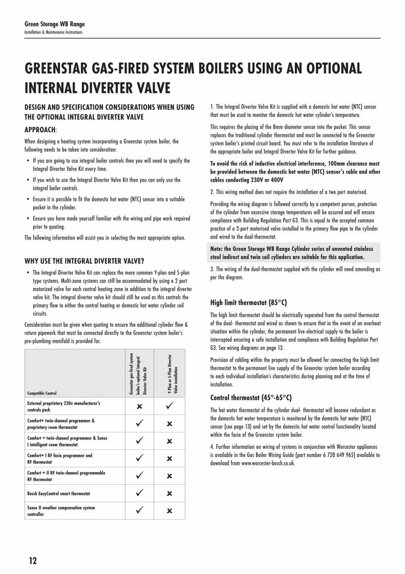
WHY USE THE INTEGRAL DIVERTER VALVE?• The Integral Diverter Valve Kit can replace the more common Y-plan and S-plan
type systems. Multi-zone systems can still be accommodated by using a 2 port motorized valve for each central heating zone in addition to the integral diverter valve kit. The integral diverter valve kit should still be used as this controls the primary flow to either the central heating or domestic hot water cylinder coil circuits.
Consideration must be given when quoting to ensure the additional cylinder flow & return pipework that must be connected directly to the Greenstar system boiler’s pre-plumbing manifold is provided for.
Compatible Control Gree
nsta
r gas
-fire
d sy
stem
bo
iler’s
opt
iona
l Int
egra
lDi
verte
r Val
ve K
it
Y-Pl
an o
r S-P
lan
Dive
rter
Valve
insta
llatio
n
External proprietary 230v manufacturer’s controls pack Comfort+ twin-channel programmer & proprietary room thermostat Comfort + twin-channel programmer & Sense I intelligent room thermostat Comfort+ I RF facia programmer and RF thermostat Comfort + II RF twin-channel programmable RF thermostat Bosch EasyControl smart thermostat Sense II weather compensation system controller
1. The Integral Diverter Valve Kit is supplied with a domestic hot water (NTC) sensor that must be used to monitor the domestic hot water cylinder’s temperature.
This requires the placing of the 8mm diameter sensor into the pocket. This sensor replaces the traditional cylinder thermostat and must be connected to the Greenstar system boiler’s printed circuit board. You must refer to the installation literature of the appropriate boiler and Integral Diverter Valve Kit for further guidance.
To avoid the risk of inductive electrical interference, 100mm clearance must be provided between the domestic hot water (NTC) sensor’s cable and other cables conducting 230V or 400V
2. This wiring method does not require the installation of a two port motorised.
Providing the wiring diagram is followed correctly by a competent person, protection of the cylinder from excessive storage temperatures will be assured and will ensure compliance with Building Regulation Part G3. This is equal to the accepted common practice of a 2-port motorised valve installed in the primary flow pipe to the cylinder and wired to the dual-thermostat.
Note: the Green Storage WB Range Cylinder series of unvented stainless steel indirect and twin coil cylinders are suitable for this application.
3. The wiring of the dual-thermostat supplied with the cylinder will need amending as per the diagram.
High limit thermostat (85°C)
The high limit thermostat should be electrically separated from the control thermostat of the dual- thermostat and wired as shown to ensure that in the event of an overheat situation within the cylinder, the permanent live electrical supply to the boiler is interrupted ensuring a safe installation and compliance with Building Regulation Part G3. See wiring diagrams on page 13.
Provision of cabling within the property must be allowed for connecting the high limit thermostat to the permanent live supply of the Greenstar system boiler according to each individual installation’s characteristics during planning and at the time of installation.
Control thermostat (45°-65°C)
The hot water thermostat of the cylinder dual- thermostat will become redundant as the domestic hot water temperature is monitored by the domestic hot water (NTC) sensor (see page 13) and set by the domestic hot water control functionality located within the facia of the Greenstar system boiler.
4. Further information on wiring of systems in conjunction with Worcester appliances is available in the Gas Boiler Wiring Guide (part number 6 720 649 965) available to download from www.worcester-bosch.co.uk.

13
Green Storage WB RangeInstallation & Maintenance Instructions
The diagrams below provides references to generic terminals that feature on the various different control boards (PCBs) within Greenstar gas-fired system boilers. For specific details please refer to the installation instructions of the appropriate boiler. Other
components and other manufacturers’ components may vary in their wiring requirements, particularly thermostats. Always refer to manufacturers’ instructions which may override the detail in order to function correctly.
WIRING DIAGRAMS
A IPE 230VIN
230VOUT
L N L N LR LR FS FR
DUAL THERMOSTAT230V MAIN
SUPPLY
CYLINDERTHERMOSTAT
SAFETY LIMITTHERMOSTAT
NOT REQUIREDUSE CYLINDER SENSOR SUPPLIED
IMPORTANT NOTE:UNDER NO CIRCUMSTANCES SHOULD THE FEED TO THE LIMIT
STAT BE TAKEN THROUGH THE CONTROL STAT
ConnectorBlock
Note: links to remain in place
CYLINDER TEMPERATURE SENSOR(SUPPLIED IN DIVERTER KIT)
REFER TO THE OPTIONAL INTEGRAL DIVERTER VALVE KIT’S INSTRUCTIONS FOR ADVICEREGARDING CONNECTING THE DIVERTER VALVE MOTOR CABLE
(made safe)
N L N L N L 2 1 2 1 2 1 2 1 2 1 2 1 2 1
BUSI3 I1LFOT1T0TW1PW1PW2PC0
N E L

14
Green Storage WB RangeInstallation & Maintenance Instructions
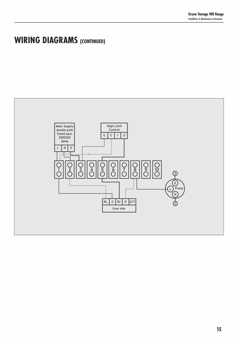
SOLAR HIGH LIMIT CONTROLThese schematic wiring diagrams depict an IMIT high limit control stat and the connections are numbered accordingly. Where an alternative is supplied, connect as per manufacturer’s instructions.
1 2
Main Supplydouble polefused spur230/220
3amp
3 54 6 7 8 9 10
L N E
High Limit Control
E C 1 2
BL G Br O G/Y
Zone Vale
WIRING DIAGRAMS (CONTINUED)
15
Green Storage WB RangeInstallation & Maintenance Instructions
1 2
Main Supplydouble polefused spur230/220
3amp
3 54 6 7 8 9 10
L N E
High Limit Control
E C 1 2
BL G Br O G/Y
Zone Vale
PumpLN
E
2
3
WIRING DIAGRAMS (CONTINUED)

16
Green Storage WB RangeInstallation & Maintenance Instructions
WIRING DIAGRAMS (CONTINUED)
VARIANT DUAL THERMOSTAT WIRINGThe diagrams shown relate to the components listed. Other components and other manufacturers’ components may vary in their wiring requirements, particularly thermostats. Always refer to manufacturers’ instructions which may override the detail in order to function correctly.
VARIANT DUAL THERMOSTAT WIRINGWiring Diagram 2 X Two Port Zone Valves (S-Plan)
VARIANT DUAL THERMOSTAT WIRINGWiring Diagram 3 Port Mid Position (Y-Plan) +2 Port Valve
1 2
2 Port (HTG)
Room Stat
3 54 6 7 8 9 10
1 2 3 4
Br G B1 O G/Y
1
2 Port (DHW)
Br G B1 O G/Y
L N E 4 5 6
Boiler
1 2 3 4
Programmer
Pump
Dual Stat
LN
C 2 C 2 1
2
2
3 1 2 3
2
3
L N
5A Supply
1 2
3 Port (HTG)
Room Stat
5A Supply 3 54 6 7 8 9 10
1 2 3 4
W G B1 O G/Y
7
2 Port (DHW)
Br G B1 O G/Y
L N E 4 5 6
Boiler
1 2 3 4
Programmer
Pump
Dual Stat
LN
C 2 C 2 1
2
2
3 1 2 3
2
3
L N

17
Green Storage WB RangeInstallation & Maintenance Instructions
WIRING DIAGRAMS (CONTINUED)
Wiring Centre Boiler
Terminal 1 Permanent Live L
Terminal 3 Permanent Neutral N
Terminal 5 Permanent Earth E
Terminal 10 Switched Live To Boiler SL B
Terminal 12 Switched Live To Pump L P
CONNECTED TO BOILER WITH PUMP OVER-RUN FACILITY
1 2
E N L 1 2 3
Red Plug - Heating 1
3 4 5 6
Wiring Diagram for Twin Zone Heating and Hot Watersystems using boiler to control pump
7 8 9 10 11 12
BL BR GR OR BL BR GR OR B1 Br Gr Or
L N E SLB LP
Yellow Plug - Heating 2 Blue Plug - Water
Boiler with over run
Pump
B1
Br
E N L 3 4 5 0 W Y G/YG/Y
Green PlugTwo Channel Programmable Room Stat With DHW Control
ProgrammableRoom Stat
Table 5: Instruction for connection to a boiler with pump over-run facility.1. Disconnect brown pre-wired pump flex from position 102. Reconnect brown pre-wired pump flex to position 123. Connect 5 core cables between boiler and wiring control centre to following positions:

18
Green Storage WB RangeInstallation & Maintenance Instructions
STERILISATION Only switch on power to the immersion heaters once sterilisation liquid has been purged and the cylinder filled with water.
FLUSHING & FILLING THE CYLINDER Check that the pressure in the expansion vessel is 3 bar (45PSI), i.e. the same as the setting of the pressure reducing valve. The valve is of the car tyre (Schrader) type. Check all the connections for tightness including any factory made connections such as the immersion heater and the temperature and pressure relief valve. Before filling, open the hot tap furthest away from the unvented cylinder to let air out.
Open the cold main isolation valve and allow the unit to fill. When water flows from the tap allow it to run for a short while to flush through any dirt, swarf or flux residue. Close the tap and open every other hot tap in turn to purge all remaining air.
INDIRECT UNITS Ensure the heating circuit has been fully flushed, carrying out commissioning in line with the boiler or solar thermal manufacturer’s commissioning instructions for the heating and the primary circuit. Primary pipework must be filled, vented and tested in accordance with the boiler manufacturer’s instructions. To ensuring all pipework is fully vented, bleed valves may need opening, especially on any raised pipes; inadequate flushing or venting could cause damage to the circulation pump.
Ensure the lever on the two port valve is set to the filling position and fill the primary circuit; ensuring the appropriate inhibitors are added in the right concentrations. When full, move the lever back. Switch the programmer to Domestic Hot Water (DHW) and allow the unit to start to heat. Adjust the dial of the dual thermostat to between 55°C and 65°C as required. Allow unit to heat up, adjust the thermostat so that the heater switches off at 60°C. Record information on the Benchmark Commissioning Checklist (Page 21).
STORAGE TEMPERATURE The recommended storage temperature setting for the cylinders is 60-65°C. In hard water areas consideration should be given to reducing this to 50-55°C. In many healthcare applications the guidance on Legionella control and safe water delivery temperatures will require storing the water at 60-65°C, distributing at 50-55°C and using thermostatic mixing valves to control the final temperature. For details consult the NHS Estates Guidance on safe hot water temperatures.
SAFETY CHECKS During heat-up double check all pipework for leaks, ensuring all connections including the immersion heaters and any pre-plumbed connections are water tight. There should have been no sign of water coming from either the expansion relief valve or the temperature/pressure relief valve. Now hold both of these safety valves fully open, allowing as much water as possible to flow through the tundish. Check that your discharge pipework is free from debris and is carrying the water away to waste efficiently. It is normal that some water will splash out of the tundish. This should be minimised by ensuring the tundish, D1 and D2 pipes are vertical to allow clean flow. Release the valves and check that they reseat properly. On completion of commissioning, fill in the Benchmark Commissioning Checklist & leave with the homeowner.
BENCHMARK SCHEME The installer must follow the Benchmark code of practice for the Benchmark certification to be valid. The Benchmark code of practice can be found online via www.centralheating.co.uk
DECOMMISSIONING & DISPOSAL Damage to the environment and risks to personal health are avoided by the proper decommissioning and disposal of this product.
To decommission your unvented hot water cylinder, isolate the electricity supply to the immersion heater and boiler/solar system, before draining the cylinder and safely disconnecting all fixtures and fittings.
The cylinder is made from many recyclable materials; therefore we strongly encourage recycling of this product at your Local Authority recycling centre at the end of its working life. For more information on proper disposal, please contact your local council or waste disposal office.
COMMISSIONING

19
Green Storage WB RangeInstallation & Maintenance Instructions
Table 6: Fault finding
Fault Possible Cause Solution
Water escaping from the case Compression fitting on hot draw-off not sealing Check/remake joint with sealing paste
Leaking cylinder Isolate supply and contact us
Cold water at hot taps Indirect - boiler not working Check boiler - consult boiler manufacturer’s instructions
Indirect - motorised valve fault Check plumbing / wiring to motorised valve
Indirect - cut-out in dual stat has operated Reset and investigate cause
Water discharges from expansion relief valve If continual - pressure reducing valve (part of inlet control set) may not be operating correctly
Check outlet pressure from inlet control set is 3 bar
If continual - expansion relief valve seat may be damaged Remove cartridge - check seat and renew if necessary
If intermittent - expansion vessel charge may have reduced / bladder perished Check pressure in expansion vessel. Recharge to 3 bar if necessary. If bladder perished replace vessel
Unit is being back pressurised With cylinder cold check pressure in cylinder. If this is the same as the incoming mains pressure then you are getting backfeed. Install a balanced cold supply (see page 5)
Water discharges from temperature & pressure relief valve
Unit has overheated - thermal controls have failed Switch off power to boiler and immersion heaters. Leave water supply on. Wait until discharge stops. Isolate water supply and replace if faulty
Milky / cloudy water Oxygenated water Water from any pressurised system will release oxygen bubbles when flowing. The bubbles will settle out
No hot water flow Cold mains off Check and open stopcock
Strainer blocked in pressure reducing valve Isolate water supply and clean
Inlet control set may be fitted incorrectly Check and refit as required
Noise during hot water draw-off -typically worse in the morning
Loose pipework Install extra clips
Water hammer Fit a shock arrestor
Hot or warm water from cold tap If tap runs cold after a minute or so the pipe is picking up heat from heating pipework
Insulate / re-route
GENERAL Servicing should only be carried out by competent installers and only spare parts approved by the manufacturer may be used. Never bypass any of the safety devices and never operate the unit without all of the safety devices being in place and fully operational.
DRAINING Isolate from the electrical supply to prevent the immersion heaters burning out. Turn off the boiler. Isolate the unit from the cold mains. Attach a hose to the draining tap ensuring that it reaches to a level below the unit (this will ensure an efficient syphon is set up and the maximum amount of water is drained from the unit). First open the hot tap closest to the unit and then open the draining tap.
Warning: water drained off may be very hot!
Important: After draining the cylinder do not close the hot tap until the cylinder has fully cooled, failure to follow this instruction may result in damage to the cylinder and will invalidate the guarantee.
ANNUAL MAINTENANCE The unvented cylinder requires an annual service in order to ensure safe working and optimum performance and to maintain the guarantee. It is essential that the following checks are performed by a competent installer on an annual basis. Commonly this is done at the same time as the annual boiler service.
1) Twist the cap of the expansion relief valve on the inlet control set and allow water to flow for 5 seconds. Release and make sure it reseats correctly. Repeat with the temperature & pressure relief valve. In both cases check that the discharge pipework is carrying the water away adequately. If not, check for blockages etc. and clear.
Warning: the water discharged may be very hot!
2) Check that any immersion heaters fitted are working correctly and that they are controlling the water at a temperature between 55ºC and 65ºC.
3) Check the pressure in the expansion vessel is charged to 3 bar. Turn off the water supply to the unit and open a hot tap first. The air valve on expansion vessel is a Schrader (car tyre) type. Air, nitrogen or CO2 may be used to charge the expansion vessel.
4) Unscrew the head on the inlet control set and clean the mesh filter within (some water may escape).
5) The Service Record on page 22 of this manual must be updated at each service.
Your guarantee may be void without proof of annual servicing.
SERVICING

20
Green Storage WB RangeInstallation & Maintenance Instructions
INFORMATION FOR HOMEOWNERS
SPARE PARTS See insert sheet for a list of part numbers.
USER INSTRUCTIONS Your stainless system is automatic in normal use and requires only annual servicing, normally this is timed to coincide with the annual boiler or solar system service. You should employ a competent installer to perform the annual service and complete the benchmark log to maintain your 25-year guarantee on the inner vessel.
If water is flowing from the safety valves through the tundish, this indicates a fault in your heating system and action is needed.
If this water is hot, turn the boiler, immersion heater and/or solar system off. Do not turn off the water until the discharge runs cool. The discharge may also stop.
Call out a competent installer to diagnose the fault. Tell them you have a fault on your hot water system and that the system includes an unvented hot water cylinder.
AFTER DRAINING Important: After draining the cylinder, the hot tap must be left fully open until the cylinder has fully cooled, failure to follow this instruction may result in damage to the cylinder & will invalidate the guarantee.
The installer must follow the Benchmark code of practice for the Benchmark certification to be valid. Please see page 2 and the Guarantee terms and conditions on pages 23 for further details.
SPECIFICATION - CYLINDER DETAILS & PERFORMANCE Please refer to the insert sheet that came with this installation manual.
BENCHMARK SCHEME The installer must follow the Benchmark code of practice for the Benchmark certification and your 25-year guarantee to be valid. The Benchmark code of practice can be found online via www.centralheating.co.uk.
Worcester Bosch is a licensed member of the Benchmark Scheme which aims to improve the standards of installation and commissioning of domestic heating and hot water systems in the UK and to encourage regular servicing to optimise safety, efficiency and performance.
Benchmark is managed and promoted by the Heating and Hotwater Industry Council. For more information visit www.centralheating.co.uk
Important: Please ensure that the installer has fully completed the Benchmark Commissioning Checklist on page 21 of the installation instructions supplied with the product and that you have signed it to say that you have received a full and clear explanation of its operation.
The installer is legally required to complete this Benchmark Commissioning Checklist as a means of complying with the appropriate Building Regulations.
All installations must be notified to Local Area Building Control either directly or through a Competent Persons Scheme. A Building Regulations Compliance Certificate will then be issued to the customer who should, on receipt, write the Notification Number on the Benchmark Commissioning Checklist. This product should be serviced regularly to optimise its safety, efficiency and performance. The service engineer should complete the relevant Service Record Commissioning after each service. The Benchmark Commissioning Checklist and Service Record will be required in the event of any guarantee claim.

MAINS PRESSURE HOT WATER STORAGE SYSTEM COMMISSIONING CHECKLIST
* All installations in England and Wales must be notified to Local Authority Building Control (LABC) either directly or through a Competent Persons Scheme. A Building Regulations Compliance Certificate will then be issued to the customer.
©Heating and Hotwater Industry Council (HHIC) www.centralheating.co.uk
ALL SYSTEMS PRIMARY SETTINGS (indirect heating only)
Is the primary circuit a sealed or open vented system? Sealed Open
What is the maximum primary flow temperature? °C
ALL SYSTEMS
What is the incoming static cold water pressure at the inlet to the system? bar
Has a strainer been cleaned of installation debris (if fitted)? Yes No
Is the installation in a hard water area (above 200ppm)? Yes No
If yes, has a water scale reducer been fitted? Yes No
What type of scale reducer has been fitted?
What is the hot water thermostat set temperature? °C
What is the maximum hot water flow rate at set thermostat temperature (measured at high flow outlet)? l/min
Time and temperature controls have been fitted in compliance with Part L of the Building Regulations? Yes
Type of control system (if applicable) Y Plan S Plan Other
Is the cylinder solar (or other renewable) compatible? Yes No
What is the hot water temperature at the nearest outlet? °C
All appropriate pipes have been insulated up to 1 metre or the point where they become concealed Yes
UNVENTED SYSTEMS ONLY
Where is the pressure reducing valve situated (if fitted)?
What is the pressure reducing valve setting? bar
Has a combined temperature and pressure relief valve and expansion valve been fitted and discharge tested? Yes No
The tundish and discharge pipework have been connected and terminated to Part G of the Building Regulations Yes
Are all energy sources fitted with a cut out device? Yes No
Has the expansion vessel or internal air space been checked? Yes No
THERMAL STORES ONLY
What store temperature is achievable? °C
What is the maximum hot water temperature? °C
ALL INSTALLATIONS
The hot water system complies with the appropriate Building Regulations Yes
The system has been installed and commissioned in accordance with the manufacturer’s instructions Yes
The system controls have been demonstrated to and understood by the customer Yes
The manufacturer’s literature, including Benchmark Checklist and Service Record, has been explained and left with the customer Yes
Commissioning Engineer’s Signature
Customer’s Signature(To confirm satisfactory demonstration and receipt of manufacturer’s literature)
This Commissioning Checklist is to be completed in full by the competent person who commissioned the storage system as a means of demonstrating compliance with the appropriate Building Regulations and then handed to the customer to keep for future reference.
Failure to install and commission this equipment to the manufacturer’s instructions may invalidate the warranty but does not affect statutory rights.
Customer Name Telephone Number
Address
Cylinder Make and Model
Cylinder Serial Number
Commissioned by (print name) Registered Operative ID Number
Company Name Telephone Number
Company Address
Commissioning Date
To be completed by the customer on receipt of a Building Regulations Compliance Certificate*:
Building Regulations Notification Number (if applicable)

SERVICE RECORDIt is recommended that your hot water system is serviced regularly and that the appropriate Service Record is completed.
Service Provider Before completing the appropriate Service Record below, please ensure you have carried out the service as described in the manufacturer’s instructions.
SERVICE 1 Date
Engineer Name
Company Name
Telephone Number
Comments
Signature
SERVICE 2 Date
Engineer Name
Company Name
Telephone Number
Comments
Signature
SERVICE 3 Date
Engineer Name
Company Name
Telephone Number
Comments
Signature
SERVICE 4 Date
Engineer Name
Company Name
Telephone Number
Comments
Signature
SERVICE 5 Date
Engineer Name
Company Name
Telephone Number
Comments
Signature
SERVICE 6 Date
Engineer Name
Company Name
Telephone Number
Comments
Signature
SERVICE 7 Date
Engineer Name
Company Name
Telephone Number
Comments
Signature
SERVICE 8 Date
Engineer Name
Company Name
Telephone Number
Comments
Signature
SERVICE 9 Date
Engineer Name
Company Name
Telephone Number
Comments
Signature
SERVICE 10 Date
Engineer Name
Company Name
Telephone Number
Comments
Signature

23
Green Storage WB RangeInstallation & Maintenance Instructions
This guarantee applies only to products & parts supplied by Kingspan, the unvented cylinder manufacturer and its associated brands. Kingspan guarantees to the homeowner that for a period of five years from the date of commissioning, that the products and associated components installed will be free from defects in materials and workmanship, subject to the conditions set out below.
Note: this guarantee excludes all pipework and connections and excludes any ancillary equipment that may be connected to the product (e.g. descaling equipment, water softeners).
The guarantee is extended to a total of 25 years for the stainless steel inner vessel in domestic properties and 5 years for parts supplied with the cylinder.
This guarantee means that the manufacturer will take responsibility for the cost of guarantee repair of a product by a Service Engineer approved by the manufacturer, so that the product shall conform to the manufacturers specification.
The manufacturer reserves the right, at its discretion, to replace a product or major component where it considers it to be beyond economical repair.
In the event of a breakdown during the guarantee period contact our customer service department. Guarantee repair is free of charge to you for any parts and labour, providing all the guarantee conditions have been met. Please read the following conditions before registering your product and before seeking any guarantee service support.
Important: You must complete the Registration Card provided & return to: Customer Service Department
The product must be maintained by a competent person* within 12 months after commissioning, and thereafter at 12-monthly intervals. As the manufacturer, we reserve the right to seek evidence of this maintenance to our reasonable satisfaction, before approving any guarantee servicing / repairs. This may include evidence of completed Service Record and service agreement / invoice.
* A competent person is defined as a person representing a business, who has been adjudged by an accredited body (an example of which is BPEC) to be sufficiently competent to self-certify that its work complies with Document (G) Part 3 of the Building Regulations of England and Wales. May include SEI registered installers and/or FAS trained plumbers who have completed the renewables technology module.
Any exchanged component will become the legal property of the manufacturer. This guarantee is valid provided that:
• The product has been installed by a competent installer and as per the instructions contained in the installation manual and all relevant Codes of Practice and Regulations in force at the time of installation.
• Any disinfection has been carried out in accordance with BS EN 806:4.
• The product has not been modified in any way.
• The system is fed from domestic mains water supply compliant with Water Regulations 2000.
• The product has only been used for the storage of wholesome water (max. 250mg/l chloride); for hard water areas, the use of an electrolytic scale reducer is recommended.
• Any 3rd party labour charges associated with replacing the unit or any of its components have been authorised in advance by the Customer Service/ Technical Support team.
• It has only been used for the storage of potable water.
• The product has not been subjected to frost, nor has it been tampered with or been subjected to misuse or neglect.
• No factory fitted parts have been removed for unauthorised repair or replacement.
• The BenchmarkTM Commissioning Checklist and Service Record included with this product installation manual have been completed.
• Regular maintenance has been carried out by a competent person in accordance with the requirements set out in the maintenance section of the installation manual.
• The owner or installer has registered the product with the manufacturer’s Customer Service department within 30 days of commissioning/occupation (in new build). Failure to do so may result in a reduced guarantee period.
• Evidence of purchase and date of supply must be submitted upon making a claim.
• Only replacement parts authorised by the manufacturer have been used.
• If a defect arises and a valid claim is received within the guarantee period, at its option and to the extent permitted by law the manufacturer shall either:
1) Repair the defect at no charge, using new or refurbished replacement parts or
2) Exchange the product with a product that is new or which has been manufactured using new or serviceable used parts or
3) Refund the purchase price or a reasonable proportion of the purchase price. The manufacturer reserves the right to inspect the product at your home before proceeding with any guarantee repair or replacement.
Any valid guarantee claims or guarantee service does not extend the original guarantee period. Information on extended guarantee is available upon request.
The guarantee only applies to the property at which the product was originally installed and applies only to properties in the United Kingdom and Ireland. The guarantee is fully transferable from a change of legal ownership of the property.
Exclusions The manufacturer will not be liable for any fault or costs arising from incorrect installation, incorrect application, lack of regular maintenance or neglect, accidental damage, malicious damage, misuse, any alteration, tampering or repair carried by a non-competent person.
The guarantee does not cover: • The product, if the factory fitted temperature and
pressure relief valve has been tampered with or removed.
• The effects of scale build up or the effects of corrosion.
• Any consequential losses caused by the failure or malfunction of the product.
• Faults and any associated costs arising from lack of power or water.
• Failure incurred by water contamination, air pollution and natural disasters.
• Installations outside the United Kingdom or Ireland.
• Any consequential loss, loss of profits, revenues or receipts howsoever arising from any non-conformity or defect affecting the product or from any delay in repair or replacement of the product.
• Any loss or damage caused by delay in conduct of services or supply of parts required to rectify the non-conformity or defect.
• Cost of repair or replacement of any product consumables or decorative finishes, such as filters and casings.
The manufacturer shall not be responsible for any consequential damage, howsoever caused.
This guarantee does not affect any legal rights you may have as a consumer under applicable national legislation governing your purchase of this product.
Manufactured by, Kingspan Water & Energy, Tadman Street, Wakefield, West Yorkshire, WF1 5QU, www.kingspan.com
The manufacturer shall make final determination as to the validity of any guarantee claim, and shall be entitled to charge you all reasonable costs incurred in investigating the claim where no fault is found, or the guarantee claim is rejected in accordance with these conditions.
GUARANTEE - TERMS & CONDITIONS

24
Green Storage WB RangeInstallation & Maintenance Instructions