Embed Size (px)
Citation preview
Lice
nsed
cop
y: T
he U
nive
rsity
of H
ong
Kon
g, T
he U
nive
rsity
of H
ong
Kon
g, V
ersi
on c
orre
ct a
s of
04/
03/2
009
05:0
6, (
c)B
SI
BRITISH STANDARD
BS EN 1473:2007Installation and equipment for liquefied natural gas — Design of onshore installations
The European Standard EN 1473:2007 has the status of a British Standard
ICS 75.200
�������������� ���������������������������������������������������

BS EN 1473:2007
Lice
nsed
cop
y: T
he U
nive
rsity
of H
ong
Kon
g, T
he U
nive
rsity
of H
ong
Kon
g, V
ersi
on c
orre
ct a
s of
04/
03/2
009
05:0
6, (
c)B
SI
This British Standard was published under the authority of the Standards Policy and Strategy Committee on 28 February 2007
© BSI 2007
ISBN 978 0 580 50229 3
National foreword
This British Standard was published by BSI. It is the UK implementation of EN 1473:2007. It supersedes BS EN 1473:1997 which is withdrawn.The UK participation in its preparation was entrusted to Technical Committee GSE/38, Installation and equipment for LNG.A list of organizations represented on GSE/38 can be obtained on request to its secretary.This publication does not purport to include all the necessary provisions of a contract. Users are responsible for its correct application.Compliance with a British Standard cannot confer immunity from legal obligations.
Amendments issued since publication
Amd. No. Date Comments
EUROPEAN STANDARD
NORME EUROPÉENNE
EUROPÄISCHE NORM
EN 1473
January 2007
ICS 75.200 Supersedes EN 1473:1997
English Version
Installation and equipment for liquefied natural gas - Design ofonshore installations
Installations et équipements de gaz naturel liquéfié -Conception des installations terrestres
Anlagen und Ausrüstung für Flüssigerdgas - Auslegung vonlandseitigen Anlagen
This European Standard was approved by CEN on 25 November 2006.
CEN members are bound to comply with the CEN/CENELEC Internal Regulations which stipulate the conditions for giving this EuropeanStandard the status of a national standard without any alteration. Up-to-date lists and bibliographical references concerning such nationalstandards may be obtained on application to the CEN Management Centre or to any CEN member.
This European Standard exists in three official versions (English, French, German). A version in any other language made by translationunder the responsibility of a CEN member into its own language and notified to the CEN Management Centre has the same status as theofficial versions.
CEN members are the national standards bodies of Austria, Belgium, Bulgaria, Cyprus, Czech Republic, Denmark, Estonia, Finland,France, Germany, Greece, Hungary, Iceland, Ireland, Italy, Latvia, Lithuania, Luxembourg, Malta, Netherlands, Norway, Poland, Portugal,Romania, Slovakia, Slovenia, Spain, Sweden, Switzerland and United Kingdom.
EUROPEAN COMMITTEE FOR STANDARDIZATIONC OM ITÉ EUR OP ÉEN DE NOR M ALIS AT IONEUROPÄISCHES KOMITEE FÜR NORMUNG
Management Centre: rue de Stassart, 36 B-1050 Brussels
© 2007 CEN All rights of exploitation in any form and by any means reservedworldwide for CEN national Members.
Ref. No. EN 1473:2007: E
Lice
nsed
cop
y: T
he U
nive
rsity
of H
ong
Kon
g, T
he U
nive
rsity
of H
ong
Kon
g, V
ersi
on c
orre
ct a
s of
04/
03/2
009
05:0
6, (
c)B
SI
EN 1473:2007 (E)
2
Contents Page
Foreword..............................................................................................................................................................3 1 Scope ......................................................................................................................................................5 2 Normative references ............................................................................................................................5 3 Terms and definitions ...........................................................................................................................8 4 Safety and environment ......................................................................................................................12 5 Jetties and marine facilities................................................................................................................28 6 Storage and retention systems ..........................................................................................................29 7 LNG pumps...........................................................................................................................................40 8 Vaporisation of LNG ............................................................................................................................41 9 Pipe-work..............................................................................................................................................44 10 Reception/send out of natural gas.....................................................................................................55 11 Boil off recovery and treatment plants..............................................................................................56 12 Auxiliary circuits and buildings .........................................................................................................59 13 Hazard management............................................................................................................................64 14 Control and monitoring systems .......................................................................................................74 15 Construction, commissioning and turnaround ................................................................................78 16 Preservation and corrosion protection .............................................................................................80 17 Training for operations .......................................................................................................................80 18 Pre-operational marine training .........................................................................................................81 Annex A (normative) Thermal radiation threshold values ............................................................................82 Annex B (normative) Definitions of reference flow rates..............................................................................85 Annex C (informative) Seismic classification.................................................................................................89 Annex D (normative) Specific requirements for LNG pumps.......................................................................91 Annex E (normative) Specific requirements for LNG vaporisers.................................................................97 Annex F (normative) Criteria for the design of pipes ..................................................................................103 Annex G (informative) Description of the different types of onshore LNG installations.........................104 Annex H (informative) Definition of different types of LNG tanks..............................................................106 Annex J (informative) Frequency ranges......................................................................................................113 Annex K (informative) Classes of consequence ..........................................................................................114 Annex L (informative) Levels of risk..............................................................................................................115 Annex M (informative) Typical process steps of liquefaction ....................................................................117 Annex N (informative) Odourant systems.....................................................................................................126 Bibliography ....................................................................................................................................................129
Lice
nsed
cop
y: T
he U
nive
rsity
of H
ong
Kon
g, T
he U
nive
rsity
of H
ong
Kon
g, V
ersi
on c
orre
ct a
s of
04/
03/2
009
05:0
6, (
c)B
SI
EN 1473:2007 (E)
3
Foreword
This document (EN 1473:2007) has been prepared by Technical Committee CEN/TC 282 “Installation and equipment for LNG”, the secretariat of which is held by AFNOR.
This European Standard shall be given the status of a national standard, either by publication of an identical text or by endorsement, at the latest by July 2007, and conflicting national standards shall be withdrawn at the latest by July 2007.
This document supersedes EN 1473:1997.
According to the CEN/CENELEC Internal Regulations, the national standards organizations of the following countries are bound to implement this European Standard: Austria, Belgium, Bulgaria, Cyprus, Czech Republic, Denmark, Estonia, Finland, France, Germany, Greece, Hungary, Iceland, Ireland, Italy, Latvia, Lithuania, Luxembourg, Malta, Netherlands, Norway, Poland, Portugal, Romania, Slovakia, Slovenia, Spain, Sweden, Switzerland and United Kingdom.
Lice
nsed
cop
y: T
he U
nive
rsity
of H
ong
Kon
g, T
he U
nive
rsity
of H
ong
Kon
g, V
ersi
on c
orre
ct a
s of
04/
03/2
009
05:0
6, (
c)B
SI

EN 1473:2007 (E)
4
Introduction
The objective of this European Standard is to give functional guidelines for LNG installations. It recommends procedures and practices that will result in safe and environmentally acceptable design, construction and operation of LNG plants. It need not be applied retrospectively, but application is recommended when major modifications of existing installations are being considered.
Lice
nsed
cop
y: T
he U
nive
rsity
of H
ong
Kon
g, T
he U
nive
rsity
of H
ong
Kon
g, V
ersi
on c
orre
ct a
s of
04/
03/2
009
05:0
6, (
c)B
SI
EN 1473:2007 (E)
5
1 Scope
This European Standard gives guidelines for the design, construction and operation of all onshore liquefied natural gas (LNG) installations including those for the liquefaction, storage, vaporisation, transfer and handling of LNG.
This European Standard is valid for the following plant types:
LNG export installations (plant), between the designated gas inlet boundary limit, and the ship manifold;
LNG receiving installations (plant), between the ship manifold and the designated gas outlet boundary limit;
peak-shaving plants, between designated gas inlet and outlet boundary limits.
A short description of each of these installations is given in Annex G.
Satellite plants are excluded from this European Standard. Satellite plants with storage capacity of less than 200 t are covered by EN 13645.
2 Normative references
The following referenced documents are indispensable for the application of this document. For dated references, only the edition cited applies. For undated references, the latest edition of the referenced document (including any amendments) applies.
EN 287-1, Qualification test of welders — Fusion welding — Part 1: Steels
EN 473, Non destructive testing — Qualification and certification of NDT personnel — General principles
EN 571-1, Non destructive testing — Penetrant testing — Part 1: General principles
EN 809, Pumps and pump units for liquids — Common safety requirements
EN 970, Non-destructive examination of fusion welds — Visual examination
EN 1092-1, Flanges and their joints — Circular flanges for pipes, valves, fittings and accessories, PN-designated — Part 1: Steel flanges
EN 1127-1, Explosive atmospheres — Explosion prevention and protection — Part 1: Basic concepts and methodology
EN 1160, Installations and equipment for liquefied natural gas — General characteristics of liquefied natural gas
EN 1435, Non-destructive examination of welds — Radiographic examination of welded joints
EN 1474, Installation and equipment for liquefied natural gas — Design and testing of loading/unloading arms
EN 1514-1, Flanges and their joints — Dimensions of gaskets for PN-designated flanges — Part 1: Non-metallic flat gaskets with or without inserts
EN 1532, Installation and equipment for liquefied natural gas — Ship to shore interface
EN 1714, Non-destructive examination of welds — Ultrasonic examination of welded joints
Lice
nsed
cop
y: T
he U
nive
rsity
of H
ong
Kon
g, T
he U
nive
rsity
of H
ong
Kon
g, V
ersi
on c
orre
ct a
s of
04/
03/2
009
05:0
6, (
c)B
SI
EN 1473:2007 (E)
6
EN 1776, Gas supply systems — Natural gas measuring stations — Functional requirements
EN 1991-1-2, Eurocode 1 —Actions on structures — Part 1-2: General actions - Actions on structures exposed to fire
EN 1992-1-1, Eurocode 2 : Design of concrete structures — Part 1-1: General rules and rules for buildings
EN 1992-1-2, Eurocode 2 : Design of concrete structures — Part 1-2: General rules - Structural fire design
EN 1993-1-1, Eurocode 3 : Design of steel structures — Part 1-1: General rules and rules for buildings
EN 1993-1-2, Eurocode 3 : Design of steel structures — Part 1-2: General rules — Structural fire design
EN 1994-1-1, Eurocode 4 — Design of composite steel and concrete structures — Part 1-1: General rules and rules for buildings
EN 1994-1-2, Eurocode 4 — Design of composite steel and concrete structures — Part 1-2: General rules — Structural fire design
EN 1998-1, Eurocode 8 : Design of structures for earthquake resistance — Part 1: General rules, seismic actions and rules for buildings
EN 1998-5, Eurocode 8: Design of structures for earthquake resistance — Part 5: Foundations, retaining structures and geotechtonical aspects
EN 10204, Metallic products — Types of inspection documents
EN 12065, Installations and equipment for liquefied natural gas — Testing of foam concentrates designed for generation of medium and high expansion foam and of extinguishing powders used on liquefied natural gas fires
EN 12066, Installations and equipment for liquefied natural gas — Testing of insulating linings for liquefied natural gas impounding areas
EN 12162, Liquid pumps — Safety requirements — Procedure for hydrostatic testing
EN 12308, Installation and equipment for LNG — Suitability testing of gaskets designed for flanged joints used on LNG piping
EN 12434, Cryogenic vessels — Cryogenic flexible hoses
EN 12567, Industrial valves — Isolating valves for LNG — Specification for suitability and appropriate verification tests
EN 13445 (all parts), Unfired pressure vessels
EN 13480 (all parts), Metallic industrial piping
EN 14620-1:2006, Design and manufacture of site built, vertical, cylindrical, flat-bottomed steel tanks for the storage of refrigerated, liquefied gases with operating temperatures between 0°C and -165°C – Part 1: General
EN 14620 (all parts), Design and manufacture of site built, vertical, cylindrical, flat-bottomed steel tanks for the storage of refrigerated, liquefied gases with operating temperatures between 0 °C and – 165 °C
EN 60034-5, Rotating electrical machines — Part 5: Degrees of protection provided by the integral design of rotating electrical machines (IP code) — Classification (IEC 60034-5:2000)
Lice
nsed
cop
y: T
he U
nive
rsity
of H
ong
Kon
g, T
he U
nive
rsity
of H
ong
Kon
g, V
ersi
on c
orre
ct a
s of
04/
03/2
009
05:0
6, (
c)B
SI
EN 1473:2007 (E)
7
EN 60079-0, Electrical apparatus for explosive gas atmospheres — Part 0: General requirements (IEC 60079-0:2004)
EN 60079-1, Electrical apparatus for explosive gas atmospheres — Part 1: Flameproof enclosures ”d” (IEC 60079-1:2003)
EN 60079-2, Electrical apparatus for explosive gas atmospheres — Part 2: Pressurized enclosures ”p” (IEC 60079-2:2001)
EN 60079-7, Electrical apparatus for explosive gas atmospheres — Part 7: Increased safety ”e” (IEC 60079-7:2003)
EN 60079-10, Electrical apparatus for explosive gas atmospheres — Part 10: Classification of hazardous areas (IEC 60079-10:2002)
EN 60079-14, Electrical apparatus for explosive gas atmospheres — Part 14: Electrical installations in hazardous areas (other than mines) (IEC 60079-14:2002)
EN 60079-17, Electrical apparatus for explosive gas atmospheres — Part 17: Inspection and maintenance of electrical installations in hazardous areas (other than mines) (IEC 60079-17:2002)
EN 60079-18, Electrical apparatus for explosive gas atmospheres — Part 18: Construction, test and marking of type of protection encapsulation "m" electrical apparatus (IEC 60079-18:2004)
EN 60079-25, Electrical apparatus for explosive gas atmospheres — Part 25: Intrinsically safe systems (IEC 60079-25:2003)
EN 60079-26, Electrical apparatus for explosive gas atmospheres — Part 26: Construction, test and marking of group II category 1 G electrical apparatus
EN 60529, Degrees of protection provided by enclosures (IP Code) (IEC 60529:1989)
EN 61508-1, Functional safety of electrical/electronic/programmable electronic safety-related systems — Part 1: General requirements (IEC 61508-1:1998 + Corrigendum 1999)
EN ISO 1460, Metallic coatings — Hot dip galvanized coatings on ferrous materials — Gravimetric determination of the mass per unit area (ISO 1460:1992)
EN ISO 1461, Hot dip galvanized coatings on fabricated iron and steel articles — Specifications and test methods (ISO 1461:1999)
EN ISO 9001, Quality management systems — Requirements (ISO 9001:2000)
EN ISO 10456, Building materials and products — Procedures for determining declared and design thermal values (ISO 10456:1999)
EN ISO 10497, Testing of valves — Fire type-testing requirements (ISO 10497:2004)
EN ISO 12241, Thermal insulation for building equipment and industrial installations — Calculation rules (ISO 12241:1998)
EN ISO 12944 (all parts), Paints and varnishes — Corrosion protection of steel structures by protective paint systems (ISO 12944:1998)
EN ISO 13709, Centrifugal pumps for petroleum, petrochemical and natural gas industries (ISO 13709:2003)
EN ISO 15607, Specification and qualification of welding procedures for metallic materials — General rules (ISO 15607:2003)
Lice
nsed
cop
y: T
he U
nive
rsity
of H
ong
Kon
g, T
he U
nive
rsity
of H
ong
Kon
g, V
ersi
on c
orre
ct a
s of
04/
03/2
009
05:0
6, (
c)B
SI
EN 1473:2007 (E)
8
EN ISO 15609-1, Specification and qualification of welding procedures for metallic materials — Welding procedure specification - Part 1: Arc welding (ISO 15609-1:2004)
EN ISO 15614-1, Specification and qualification of welding procedures for metallic materials — Welding procedure test - Part 1: Arc and gas welding of steels and arc welding of nickel and nickel alloys (ISO 15614-1:2004)
IEC 60079-4, Electrical apparatus for explosive gas atmospheres — Part 4: Method of test for ignition temperature
IEC 60079-5, Electrical apparatus for explosive gas atmospheres — Part 5: Powder filling "q"
IEC 60079-6, Electrical apparatus for explosive gas atmospheres — Part 6: Oil-immersion ”o”
IEC 60079-11, Explosive atmospheres — Part 11:Equipment protection by intrinsic safety ”i”
IEC 60079-13, Electrical apparatus for explosive gas atmospheres — Part 13: Construction and use of rooms or buildings protected by pressurization
IEC 60079-15, Electrical apparatus for explosive gas atmospheres — Part 15: Construction, test and marking of type of protection ”n” electrical apparatus
IEC/TR 60079-16, Electrical apparatus for explosive gas atmospheres — Part 16: Artificial ventilation for the protection of analyzer(s) houses
IEC 60079-19, Electrical apparatus for explosive gas atmospheres — Part 19: Repair and overhaul for apparatus used in explosive atmospheres (other than mines or explosives)
IEC/TR3 60079-20, Electrical apparatus for explosive gas atmospheres — Part 20: Data for flammable gases and vapours, relating to the use of electrical apparatus
IEC 60079-27, Electrical apparatus for explosive gas atmospheres — Part 27: Fieldbus intrinsically safe concept (FISCO) and Fieldbus non-incendive concept (FNICO)
IEC 60364-5-54, Electrical installations of buildings — Part 5-54: Selection and erection of electrical equipment — Earthing arrangements, protective conductors and protective bonding conductors
3 Terms and definitions
For the purposes of this document, the following terms and definitions apply.
3.1 abnormal operation plant operation such as plant trip, the production and disposal of off-spec products and also operation with production equipment failed or on maintenance are modes of abnormal operation and are not accidental events
3.2 accidental event event that arises from an uncontrolled or unplanned situation with safety and/or environmental consequences
3.3 boundary property line on land or water inside which the operator/owner has full control and authority, or exclusive use
Lice
nsed
cop
y: T
he U
nive
rsity
of H
ong
Kon
g, T
he U
nive
rsity
of H
ong
Kon
g, V
ersi
on c
orre
ct a
s of
04/
03/2
009
05:0
6, (
c)B
SI
EN 1473:2007 (E)
9
3.4 bund or bund wall raised impermeable structure, able to withstand the static pressure and temperature of the spilled liquid, around the perimeter of an impounding area for the confinement of hydrocarbon spills, usually associated with storage areas
3.5 condensate hydrocarbon liquids produced from primary separation of natural gas from a reservoir
NOTE Natural gas condensates consist primarily of pentanes and heavier components, although quantities of propane and butane may be dissolved within the mixture
3.6 container - primary container container in continuous contact with LNG i.e.:
the cryogenic container of the single containment tank;
the cryogenic container of the spherical tank;
the inner cryogenic container of the double containment tank, full containment tank or cryogenic concrete tank;
the cryogenic membrane of the membrane tanks
3.7 container - secondary container container in contact with LNG only in the event of a failure of the primary container i.e.:
the bund walls for single and double containment tanks and spherical tanks;
the outer container of full containment tanks or cryogenic concrete tanks;
the concrete envelope of membrane tanks
3.8 conventional onshore LNG terminal LNG export or receiving terminal that is located on-shore and has a marine transfer facility for the loading or unloading of LNG carriers
NOTE The transfer facility is located in a harbour or other sheltered coastal location and consists of a fixed structure, or wharf, capable of withstanding the berthing loads of a fully laden LNG carrier of a given specification and mooring the vessel safely alongside. The structure is connected to the shore by a trestle, tunnel or other means, facilitating the LNG transfer and ancillary services and providing safe access and egress for personnel performing maintenance or operational duties
3.9 earthquake - OBE (Operating Basis Earthquake) maximum earthquake for which no damage is sustained and restart and safe operation can continue
NOTE This higher probability event would result in no commercial loss to the installation and public safety is assured
3.10 earthquake - SSE (Safe Shutdown Earthquake) maximum earthquake event for which the essential fail-safe functions and mechanisms are designed to be preserved.
Lice
nsed
cop
y: T
he U
nive
rsity
of H
ong
Kon
g, T
he U
nive
rsity
of H
ong
Kon
g, V
ersi
on c
orre
ct a
s of
04/
03/2
009
05:0
6, (
c)B
SI
EN 1473:2007 (E)
10
NOTE Permanent damage can be expected of this lower probability event, but without the loss of overall integrity and containment. The installation would not remain in continuous service without a detailed examination and structural assessment at the ultimate limit state
3.11 ESD (Emergency Shut Down) system system that safely and effectively stops the whole plant or individual units to minimise incident escalation
3.12 flammable gases gas or vapour which, when mixed with air in certain proportions, will form a combustible gas mixture
3.13 frequency number of occurrences per unit of time
3.14 golden weld weld that cannot be pressure tested due to its nature or location and that consequently will be subjected to a high level of non-destructive examination to prove that it is safe
3.15 hazard property of a dangerous substance or physical situation with a potential for creating damage to human health and/or to environment1)
3.16 impounding area area where spills from liquid hydrocarbon storage containers may be confined or controlled, close to the source of leakage
3.17 impounding basin container within or connected to an impounding area or spill collection area where liquid hydrocarbon spills can be collected and safely confined and controlled
3.18 limit states two categories of limit states are used in the design of the load bearing structures:
the serviceability limit state (SLS), which is determined on the basis of criteria applicable to functional capability or to durability properties under normal actions;
the ultimate limit state (ULS), which is determined on the basis of the risk of failure, large plastic displacements or strains comparable to failure under augmented actions
3.19 LNG (Liquefied Natural Gas) LNG (Liquefied Natural Gas) is defined in EN 1160
3.20 LNG export terminal site at which natural gas coming by pipe from one or several gas producing fields is liquefied then stored for subsequent transport, normally by sea, to other destinations.
1) Refer to European Directive [Council Directive 96/82/EC of 9 December 1996 on the control of major-accident hazards involving dangerous substances].
Lice
nsed
cop
y: T
he U
nive
rsity
of H
ong
Kon
g, T
he U
nive
rsity
of H
ong
Kon
g, V
ersi
on c
orre
ct a
s of
04/
03/2
009
05:0
6, (
c)B
SI
EN 1473:2007 (E)
11
NOTE It has marine facilities for the transfer of LNG and can have loading stations for road, rail, barge or small LNG carriers
3.21 LNG peak-shaving plant LNG peak-shaving plants are connected to a gas network.
NOTE During the period of the year when gas demand is low, natural gas is liquefied and stored. LNG may be vaporised for short periods, when gas demand is high
3.22 LNG receiving terminal site where LNG carriers (ships) are unloaded, and where LNG is stored in tanks, vaporised and sent to the gas networks or gas consumers.
NOTE It has marine facilities for the transfer of LNG and can have loading stations for road, rail, barge or small LNG carriers
3.23 LNG satellite plant LNG satellite plants are connected to a gas network or gas consumers. LNG is supplied by road tankers, rail, barge or small LNG carriers. LNG is stored in insulated pressure vessels, vaporised and sent to the network
3.24 NGL (Natural Gas Liquid) liquid composed of light hydrocarbons (typically ethane through hexane plus) condensed from the natural gas prior to its liquefaction
3.25 normal operation operation including intermittent operation such as ship loading or unloading, start-up, maintenance, planned shutdown and commissioning
3.26 operator/occupier company responsible for the operation of the installation
3.27 owner company responsible for the safe design and construction of the installation
3.28 PASQUILL atmospheric stability factors PASQUILL atmospheric stability factors are determined as a function of the wind speed and solar radiation (see [1]). The six factors are:
A: extremely unstable;
B: moderately unstable;
C: lightly unstable;
D: neutral;
E: lightly stable;
F: moderately stable
Lice
nsed
cop
y: T
he U
nive
rsity
of H
ong
Kon
g, T
he U
nive
rsity
of H
ong
Kon
g, V
ersi
on c
orre
ct a
s of
04/
03/2
009
05:0
6, (
c)B
SI
EN 1473:2007 (E)
12
3.29 probability number in a scale from 0 to 1 which expresses the likelihood of an event occurrence
3.30 PSD (Process Shut Down) system system that safely and effectively stops individual units within the plant for process reasons
3.31 risk combination of the consequence and the frequency of a specific hazard occurring within a specified period under specified circumstances
3.32 Safety Management System management process which defines and monitors the organisational structure, responsibilities, procedures, processes and resources for determining and implementing the major accident prevention policy2)
3.33 SIL Safety Integrity Level required of a safety related system in terms of EN 61508
3.34 spill collection area area at LNG production or transfer areas where leakages can be confined or controlled, often by the use of kerbing and/or controlled sloping of paved areas
3.35 tank equipment item in its entirety for the storage of LNG.
NOTE The different types of tank are described in Annex H
3.36 transfer area area containing a piping system where flammable liquids or gases are introduced into or removed from the plant or where piping connections are connected or disconnected routinely
3.37 validated model mathematical model, the scientific basis of which is accepted to be sound and is proven to provide mathematical outputs to the relevant mathematical problem, and is shown to cover the full range of usage of the model and which has been calibrated or checked using realistic test data or results
4 Safety and environment
4.1 General
The design, procurement, construction and operation phases should all be implemented in accordance with the requirements of the Quality, Health, Safety and Environment management systems as described in EN ISO 9000 and EN ISO 14000 series.
Furthermore each phase shall be controlled by an acceptable Safety Management System.
2) Refer to European Directive [Council Directive 96/82/EC of 9 December 1996 on the control of major-accident hazards involving dangerous substances].
Lice
nsed
cop
y: T
he U
nive
rsity
of H
ong
Kon
g, T
he U
nive
rsity
of H
ong
Kon
g, V
ersi
on c
orre
ct a
s of
04/
03/2
009
05:0
6, (
c)B
SI
EN 1473:2007 (E)
13
4.2 Environmental impact
4.2.1 Environmental Impact Assessment
During the feasibility study phase of the project, a preliminary Environmental Impact Assessment (EIA) shall be carried out for the proposed location in accordance with local regulations. Consideration should be given to formally recording the base line site environmental characteristics.
When the site has been selected, a detailed EIA shall be carried out.
All emissions from the plant, that is, solid, liquid (including water), and gaseous (including noxious odours) shall be identified and measures taken to ensure they will not be harmful to persons, property, animals or vegetation. This applies not only to normal, but also to accidental emissions.
During or prior to operation an effluent management procedure shall be established. The precautions for handling toxic materials shall be identified and be regularly updated by the operator/occupier.
The environmental impact due to construction and operation shall also be assessed and undesirable levels of activities shall be eliminated or minimised and restricted. The following checklist covers the main items:
increased population, permanent and temporary;
increased road, rail and ship traffic;
increased noise levels, sudden and intermittent noise;
increased vibration levels, sudden and intermittent;
increased night working, effect of lights and their intermittent use;
flaring, intermittent and/or continuous;
warming or cooling of water.
4.2.2 Plant emissions
During the design plans shall be developed to eliminate, minimise or render harmless emissions resulting from commissioning tests, operations and maintenance activities, and shall set targets for quantities and concentrations of pollutants in emissions.
4.2.3 Emission control
The following shall be safely controlled:
combustion products;
normal or accidental venting of gas;
normal or accidental flaring of gas;
disposal of acid gas removal solvent;
disposal of spent mercury removal reactant (as the demercurisation process is not regenerative, it is necessary to store and then treat the used absorbent mass or have it removed by a licensed waste disposal contractor);
oily water condensed during dryer regeneration or from machines;
Lice
nsed
cop
y: T
he U
nive
rsity
of H
ong
Kon
g, T
he U
nive
rsity
of H
ong
Kon
g, V
ersi
on c
orre
ct a
s of
04/
03/2
009
05:0
6, (
c)B
SI
EN 1473:2007 (E)
14
in the case of water cooled equipment, hydrocarbon contamination of cooling water from leaking exchanger tubes;
disposal of waste products (including waste oil and chlorinated organic compounds);
vaporiser water;
odourant chemicals.
4.2.4 Flare/venting philosophy
Plants are to be designed around the principle of no continuous flaring or venting. Provisions should be taken during design and operation to ensure that potential gas waste streams, wherever practically possible, are recovered and not routed to flare or vent during the normal operation of the plant.
4.2.5 Noise Control
The design of the plant shall consider the effects of noise on people within the plant exposed to noise and the effect of noise on any community surrounding the plant.
It is recommended that the noise design procedure of the plant should comply with ISO 15664.
4.2.6 External traffic routes
External traffic routes near to the LNG plant shall be listed in EIA, stating the volume and nature of present traffic and also any foreseeable development caused by the plant. In particular the following shall be examined:
overland routes (roads, railways);
navigable routes (sea or river routes, canals);
air routes and the proximity of airports and aerodromes.
4.2.7 Water discharge
The impact of water discharges shall be studied (temperature, currents, winds etc).
4.3 Safety general
4.3.1 Safety philosophy approach
LNG installations shall be designed to provide generally accepted levels of risk (see Annex L) for life and property outside and inside the plant boundaries. In order to ensure this high level of safety in the LNG facilities and its surroundings, safety shall be considered throughout all the project development phases: engineering, construction, start-up, operation and decommissioning. In particular, hazard assessments, see 4.4, shall be carried out and the required safety measure implemented to ensure acceptable risk levels.
EN 13645 shows an example of a limited risk assessment.
4.3.2 Installation and its surrounding
4.3.2.1 Description of the installation
A functional description of the installation shall be written by plant area and/or by process function, for use in the safety assessment.
Lice
nsed
cop
y: T
he U
nive
rsity
of H
ong
Kon
g, T
he U
nive
rsity
of H
ong
Kon
g, V
ersi
on c
orre
ct a
s of
04/
03/2
009
05:0
6, (
c)B
SI
EN 1473:2007 (E)
15
4.3.2.2 Site study
The site study shall include, where appropriate:
a soil survey;
a study of terrain to enable the dispersion of liquid and gas clouds to be assessed;
a study of vegetation to enable, in particular, vegetation fire risks to be identified;
a study of ground water tables;
a study to identify sources of stray electrical currents (e.g. those emanating from high voltage power lines, railways);
a study of the marine aquatic environment and marine access;
a study of sea water quality and temperature;
a study of tidal conditions;
a study of shock waves and flooding (tsunami, failure of dams etc.);
a survey of the surrounding infrastructure (e.g. industrial sites, built up areas, communications);
manoeuvring areas, safety distances whilst a LNG carrier is in transit within the port and at berth (see Clause 5 and EN 1532).
The soil survey shall include:
the geotechnical survey that will enable the geo-mechanical characteristics of the subsoil to be defined;
the geological and tectonic investigation.
The geological characteristics of the region shall be investigated in sufficient detail to provide a clear understanding of the physical processes that formed the area, as well as the potential for the future seismic activity.
A more specific survey shall be done on the site and its vicinity to detect the presence of karst, gypsum, swelling clays, soluble salt deposits, soil liquefaction, mass movement etc. and their relative impact shall be evaluated.
Such phenomena are not allowed under the tank and/or equipment foundations unless it can be proved that appropriate measures have been undertaken to overcome the potential problems.
4.3.2.3 Climatology
The climatic study shall include the following points:
wind strength and direction including frequency and strength of severe storms;
temperatures;
atmospheric stability;
range and rate of change of barometric pressure;
Lice
nsed
cop
y: T
he U
nive
rsity
of H
ong
Kon
g, T
he U
nive
rsity
of H
ong
Kon
g, V
ersi
on c
orre
ct a
s of
04/
03/2
009
05:0
6, (
c)B
SI
EN 1473:2007 (E)
16
rainfall, snow, icing;
corrosive characteristic of the air;
risks of flooding;
frequency of lightning strikes;
relative humidity.
Local conditions may require other investigations.
4.3.2.4 Seismology
An earthquake is defined by the horizontal and vertical accelerations of the ground. These accelerations are described by:
their frequency spectrum;
their amplitude.
A site-specific earthquake analysis shall be performed. This shall include assessments of the risks of earthquake, tsunamis, landslides and volcanic activities. This analysis shall be presented in a Seismic Report where geological and seismic characteristics of the location of the facility and the surrounding region as well as geotectonic information shall be taken into account. As a conclusion this report shall define all seismic parameters required for the design.
The size of the region to be investigated depends on the nature of the area around the site and the geological and tectonic conditions resulting from the soil survey, see 4.3.2.2. Generally it is limited to a distance less than 320 km from the site, but in some instances it can include an entire tectonic province, larger than the above (see [23]).
A second level of analysis shall be made on the region within the 80 km from the site (regional seismo-tectonic investigation) with the aim of detecting the presence of any active geological faults (see [23]).
These investigations involve thorough research, review and evaluation of all historically reported earthquakes that have affected, or that could reasonably be expected to have affected the site.
In case of seismic faults in the immediate vicinity of the site, further investigations shall be conducted to estimate their possible activity. Faults for which inactivity cannot be confirmed are not allowed inside the site or within a distance to be determined from the soil morphology.
For details of the seismic investigations and format of response spectrum, reference is made to EN 1998-1 and EN 1998-5.
The geological, tectonic and seismological studies help to establish:
the safe shutdown earthquake (SSE);
the operating basis earthquake (OBE).
These shall be established:
probabilistically, as those that produce ground motions with the mean recurrence as a minimum interval of 5 000 years for the SSE and 475 years for the OBE, and/or,
Lice
nsed
cop
y: T
he U
nive
rsity
of H
ong
Kon
g, T
he U
nive
rsity
of H
ong
Kon
g, V
ersi
on c
orre
ct a
s of
04/
03/2
009
05:0
6, (
c)B
SI
EN 1473:2007 (E)
17
deterministically, assuming that earthquakes which are analogous to maximum historically known earthquakes are liable to occur in the future with an epicentre position which is the most severe with regard to its effects in terms of intensity on the site, while remaining compatible with geological and seismic data.
NOTE Both OBE and SSE define specific performance limits for seismic events of increasing severity for systems as defined in 4.5.2.2.
4.3.2.5 Location
During the feasibility study phase of the project site location assessments shall be carried out to ensure the suitability of the location options with regards to adjacent development. The assessment shall as a minimum consider the following:
residential development;
retail and leisure developments;
sensitive developments (schools, hospitals, retirement homes, sports stadium etc.);
industrial development;
transportation infrastructure.
When the site has been selected, a detailed site location assessment shall be carried out. The location assessment methodology and scope shall have regard for the proposed inventory of hazardous material contained on the plant and the presence and scale of adjacent existing and identified future developments, whilst being in conformance with local and national regulatory requirements.
It is recommended that:
the assessment is updated on a regular basis and when major modifications or changes take place;
the development around the plant is controlled to minimise the subsequent incompatible development.
Guidance for the probabilistic assessment acceptance criteria of site location are presented in Table L2. These minimum acceptance criteria can be adopted in the event that no such criteria exist in the country where the plant is to be built.
4.4 Hazard assessment
4.4.1 General
A hazard assessment shall be carried out during the design of the plant and it is also recommended if a major modification or change takes place.
The following methodology and requirements see annexes that show examples of frequency ranges, classes of consequences and levels of risks. However there is a variation in national and company acceptance criteria and the examples given in the informative Annexes J, K and L should be considered as minimum requirements. If more stringent local or national requirements exist they shall supersede these minimum requirements.
Lice
nsed
cop
y: T
he U
nive
rsity
of H
ong
Kon
g, T
he U
nive
rsity
of H
ong
Kon
g, V
ersi
on c
orre
ct a
s of
04/
03/2
009
05:0
6, (
c)B
SI
EN 1473:2007 (E)
18
4.4.2 Assessment
4.4.2.1 Methodology
The methodology of the hazard assessment can be deterministic and/or probabilistic.
The deterministic approach consists of:
list of potential hazards of external and internal origin;
establishment of credible hazards;
determination of the consequences;
justification of the necessary safety improvement measures to limit the consequences.
The probabilistic approach consists of:
list of potential hazards of external and internal origin;
determination of the consequences of each hazard and their allocation into classes of consequence (an example is given in Annex K);
collection/input of failure rate data;
determination of the probability or frequency of each hazard;
summation of frequency for all hazards within any one allotted consequence class and classify the frequency range for that consequence class (an example is given in Annex J);
classification of hazards in accordance with their consequences class and frequency range, in order to determine the level of risk (an example is given in Annex L).
In the event that the risk determination indicates ”Unacceptable Risk" levels (for example, risk level 3 of Annex L) the plant design or operating practices shall be altered and the assessment repeated until such time that no such “Unacceptable Risk” levels exist. In the event that the risk determination indicates normal, acceptable, risk levels (for example, risk level 1 of Annex L) no further action is considered necessary. For risk levels determined as requiring further reduction (for example risk level 2 of Annex L) additional safety measures should be considered to limit the risk to as low as reasonably practicable.
The hazard assessment can be based on conventional methods such as:
hazard and operability study (HAZOP);
failure mode effect analysis (FMEA);
event tree method (ETM);
fault tree method (FTM).
The hazard assessment procedure should be carried out during all stages of the design process. Implementation during the early stages of a project or design modification is recommended, this allows unacceptable designs to be improved in the most cost effective manner.
The probabilistic assessment minimum acceptance criteria given in Table L.1 are based on risk to personnel inside the plant boundary. Comparable categories for mass of hydrocarbon released are also given for guidance in Annex K. Alternative risk assessment methods can be used to assess the suitability of the plant
Lice
nsed
cop
y: T
he U
nive
rsity
of H
ong
Kon
g, T
he U
nive
rsity
of H
ong
Kon
g, V
ersi
on c
orre
ct a
s of
04/
03/2
009
05:0
6, (
c)B
SI
EN 1473:2007 (E)
19
design, typically business and hazardous incident escalation risk assessments. However as a minimum personnel risk should be assessed and verified as acceptable during the plant design and following major modifications.
Risk analysis and its conclusions should not compromise good engineering practices.
4.4.2.2 Identification of hazards of external origin
Studies should be undertaken to identify hazards arising from outside the plant. Such hazards can be caused by:
LNG carriers approaching the berth at excessive speed or angle;
the possibility of collision with the jetty and/or LNG carrier at berth by heavy displacement vessels passing the berth (see [23]);
the impact of projectiles and consequences of collision (ship, truck, plane etc.);
natural events (lightning, flooding, earthquakes, tidal bores, icebergs, tsunamis etc.);
ignition by high energy radio waves (see [25]);
proximity of airport and/or flight-paths;
a “domino effect” resulting from fires and/or explosions at adjacent premises;
flammable, toxic or asphyxiant drifting gas clouds;
permanent sources of ignition, such as high voltage power lines (corona effect);
the proximity of the site to any external uncontrolled sources of ignition.
4.4.2.3 Identification of hazards of internal origin
a) Hazard arising from LNG
Loss of containment of LNG and of natural gas shall be considered for all items of equipment including the loading or unloading of road tankers or LNG carriers. To simplify the study, scenarios may be established.
These scenarios shall be defined in terms of:
the probability or frequency of the hazard;
the location of the leak;
the nature of the fluid (LNG or gas, specifying the temperature);
the rate and the duration of the leakage;
the weather conditions (wind speed and direction, atmospheric stability, ambient temperature, relative humidity);
the thermal properties and the topography of the ground (including any impounding area);
the proximity of structural steelwork that may be susceptible to brittle failure due to low or cryogenic temperatures. Under certain circumstances when quantities of LNG have been introduced into water,
Lice
nsed
cop
y: T
he U
nive
rsity
of H
ong
Kon
g, T
he U
nive
rsity
of H
ong
Kon
g, V
ersi
on c
orre
ct a
s of
04/
03/2
009
05:0
6, (
c)B
SI
EN 1473:2007 (E)
20
over-pressurisation without combustion has been known to occur; this phenomena is referred to as a Rapid Phase Transition (RPT). Refer to EN 1160 and see [32] and [33].
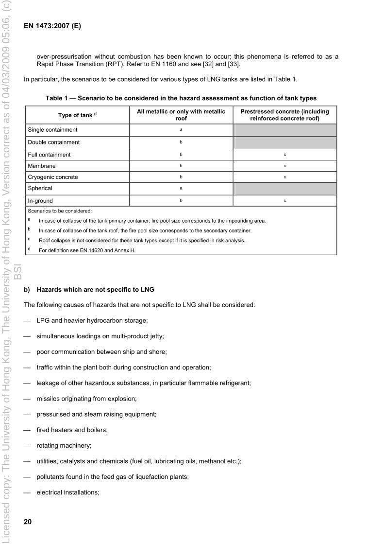
In particular, the scenarios to be considered for various types of LNG tanks are listed in Table 1.
Table 1 — Scenario to be considered in the hazard assessment as function of tank types
Type of tank d All metallic or only with metallic roof
Prestressed concrete (including reinforced concrete roof)
Single containment a Double containment b Full containment b c
Membrane b c
Cryogenic concrete b c
Spherical a In-ground b c
Scenarios to be considered: a In case of collapse of the tank primary container, fire pool size corresponds to the impounding area. b In case of collapse of the tank roof, the fire pool size corresponds to the secondary container. c Roof collapse is not considered for these tank types except if it is specified in risk analysis. d For definition see EN 14620 and Annex H.
b) Hazards which are not specific to LNG
The following causes of hazards that are not specific to LNG shall be considered:
LPG and heavier hydrocarbon storage;
simultaneous loadings on multi-product jetty;
poor communication between ship and shore;
traffic within the plant both during construction and operation;
leakage of other hazardous substances, in particular flammable refrigerant;
missiles originating from explosion;
pressurised and steam raising equipment;
fired heaters and boilers;
rotating machinery;
utilities, catalysts and chemicals (fuel oil, lubricating oils, methanol etc.);
pollutants found in the feed gas of liquefaction plants;
electrical installations;
Lice
nsed
cop
y: T
he U
nive
rsity
of H
ong
Kon
g, T
he U
nive
rsity
of H
ong
Kon
g, V
ersi
on c
orre
ct a
s of
04/
03/2
009
05:0
6, (
c)B
SI
EN 1473:2007 (E)
21
harbour installations associated with the LNG plant;
security issues (e.g. intrusion, sabotage);
accidents during construction and maintenance;
escalation of accidents.
4.4.2.4 Estimation of probabilities
The estimation of the probability associated with a given hazard, where utilised, shall be based on reliable data bases available in public domain and which are suitable for the LNG industry or on recognised methods as in 4.4.2.1 which will determine the frequency range for this hazard (see Annex J). The human factor shall be taken into account.
4.4.2.5 Estimation of consequences
The consequences of each scenario as defined above will depend on the characteristics of LNG and other phenomena described EN 1160. For the hazardous characteristics of fluids other than LNG reference shall be made to their Material Safety Data Sheets.
a) Evaporation of spilled LNG
The phenomenon of instantaneous vaporisation (flash, including possible aerosol formation) shall be taken into account.
Calculation of evaporation due to heat transfer shall be carried out using appropriate validated models.
The model shall take the following into account:
LNG flow rate and duration;
LNG composition;
nature of the ground (thermal conductivity, specific heat, density etc.);
temperature of the ground or of the water;
atmospheric conditions (ambient temperature, humidity, wind velocity);
atmospheric stability or temperature gradient.
The model shall enable the following to be determined:
pool propagation speed;
wetted area in terms of time, and, in particular, the maximum wetted area;
rate of evaporation in terms of time and, in particular, the maximum evaporation rate.
b) Atmospheric dispersion of LNG vapours
Calculation of the atmospheric dispersion of the cloud resulting from evaporation of LNG due to flashing and evaporation when in contact with the ground or water shall be carried out using appropriate validated models.
The determination of dispersion shall, as a minimum, take into account:
Lice
nsed
cop
y: T
he U
nive
rsity
of H
ong
Kon
g, T
he U
nive
rsity
of H
ong
Kon
g, V
ersi
on c
orre
ct a
s of
04/
03/2
009
05:0
6, (
c)B
SI
EN 1473:2007 (E)
22
the diameter of the evaporating pool;
the evaporation rate;
properties of the vapour;
the nature of the ground (thermal conductivity, specific heat, density etc.);
the temperature of the ground or water;
the atmospheric conditions (ambient temperature, humidity, wind speed);
atmospheric stability or temperature gradient;
site topography (surface roughness etc).
The atmospheric dispersion simulation shall be based on the combination of wind speed and atmospheric stability that can occur simultaneously and result in the longest predictable downwind dispersion distance that is exceeded less than 10 % of the time.
If no other information is available the following atmospheric condition shall be considered: F (PASQUILL) atmospheric stability or equivalent temperature gradient, for a wind of 2 m/s and a relative humidity of 50 %.
The model shall enable the determination of:
concentration contours;
the distance to the lower flammability limit.
c) Jet release of natural gas or LNG
Calculation of atmospheric dispersion resulting from jet release shall be carried out using appropriate validated models to determine as minimum, the height or the distance reached by the jet and the concentration of gas at any given point.
Sources of jet releases should include releases from atmospheric safety valves, un-ignited flare and vents. Where appropriate it shall consider possible aerosol formation.
d) Over-pressure
The ignition of natural gas can create in certain circumstances (e.g. congested areas) an explosion generating an over-pressure wave. The flammability range of mixtures of gas and air is given in EN 1160.
Recognised methods and models, for example the multi energy method (see [5]) and/or deflagration at constant speed method (see [6]) which have been validated can be used to calculate the over-pressure. This over-pressure should be specified where applicable for equipment, buildings and structures.
Where over-pressure on a tank, equipment item, building or structure is specified, it shall always be the incoming wave characteristics. In this case it may be assumed that a deflagrating explosion near the tank gives rise to an over-pressure that is applied, as a worst case assumption, to a half perimeter of the tank. The stresses in the tank caused by over pressure shall be determined by dynamic calculation. For the other structures, the stresses may be determined by static calculation.
The effect of potential over-pressure under elevated tank basis due to the ignition of a flammable mixture under the tank shall be considered.
The effects of wave reflection on the objects shall be the responsibility of the supplier.
Lice
nsed
cop
y: T
he U
nive
rsity
of H
ong
Kon
g, T
he U
nive
rsity
of H
ong
Kon
g, V
ersi
on c
orre
ct a
s of
04/
03/2
009
05:0
6, (
c)B
SI
EN 1473:2007 (E)
23
e) Radiation
Calculation of the radiation caused by ignition of the vapour from a pool or jet of LNG or release of natural gas shall be carried out using appropriate validated models.
The model shall take the following into account:
area of the pool fire or the dimensions of the flame;
surface emissive power of the pool fire or of the flame (see EN 1160);
ambient temperature, wind speed and relative humidity.
The radiation calculation shall be based on the combination of wind speed and atmospheric conditions that can occur simultaneously and result in the highest predictable radiation that is exceeded less than 10 % percent of the time.
If no other information is available the following atmospheric condition shall be considered: a wind of 10 m/s and a relative humidity of 50 %.
The model shall enable the determination of the incident radiation at various distances and elevations.
4.4.3 Safety improvement
Where the hazard assessment demonstrates that threshold values defined in Annex A are exceeded or shows that the level of risk requires improvement (see Annex L), measures shall be taken, as for example:
setting up a safety system which allows early detection of a leak and limitation of the consequences of ignitions (see 4.5 and Clause 13);
increasing the dilution of the flammable cloud;
elimination of potential sources of ignition inside a flammable cloud;
reducing evaporation rates through minimisation of heat transfer;
reducing heat radiation by water curtains, deluge systems, foam or insulation;
reducing vapour dispersion distance by warming the cloud by the use of foam or spraying;
increasing spacing between equipment;
protection of the installation against blast;
alarm systems such as break-glass units, telephones, paging systems, closed circuit television and sirens.
4.5 Safety engineering during design and construction
4.5.1 Introduction
During engineering and construction the safety shall be continuously scrutinised to guarantee the appropriate safety level with regard to the hazard assessment.
The safety management during design and construction shall include design considerations and continuous reviews as outlined respectively in 4.5.2 and 4.5.3.
Lice
nsed
cop
y: T
he U
nive
rsity
of H
ong
Kon
g, T
he U
nive
rsity
of H
ong
Kon
g, V
ersi
on c
orre
ct a
s of
04/
03/2
009
05:0
6, (
c)B
SI
EN 1473:2007 (E)
24
4.5.2 Design
4.5.2.1 Common safety design features
a) Equipment and piping design for low temperature
Design pressures and temperatures of piping and equipment shall be selected to cover all anticipated operation and upset conditions. Suitable materials are listed in EN 1160.
The stresses in pipe-work and equipment are affected by contraction/expansion phenomena due to temperature changes, the possibility of thermal shock and the method of insulation. Physical phenomena such as: liquid hammer, cavitation, flashing and two-phase flow shall be taken into consideration. The recommendations of Clause 9 are applicable. It is recommended that the main pipes are maintained in a cold condition e.g. by circulating of LNG, line weathering.
b) Hazardous area classifications
All installations shall be subjected to a hazardous area analysis (see [12] and [13]). The terms of reference for such an analysis shall be laid down in accordance with EN 1127-1 and EN 60079-10.
The form and the extent of each zone may differ slightly depending on the national or professional code used but shall be in line with the methodology set forward in EN 60079-10. Consideration shall be given to EN 1532 for the jetty, particularly for the hazardous zones generated when the LNG ship is alongside.
The selection of equipment for use in particular locations shall be determined from the hazardous zone classification of these locations in accordance with EN 1127-1 and EN/IEC series (parts 0 to 25).
c) Internal over-pressure protection
Safety devices shall be provided to cover all internal over-pressure risks including those due to fire.
It is recommended that the discharges from conventional safety devices (safety valves, relief valves) are routed to the flare/vent system or the storage tank. Tank and vaporiser safety valve releases, if not routed to the flare/vent systems, should be routed to a safe location as defined by hazard assessment.
If low and high pressure releases are routed to the same system the risk of excessive back pressure shall be avoided. If excessive back-pressure could occur in low pressure release system due to high pressure release, then separate flare/vent systems may be considered for high and low pressure releases.
d) Emergency depressurising
It is recommended that a depressurising system is provided.
The intention of this measure is to:
reduce the internal pressure;
reduce the effect of leakage;
avoid the risk of failure of LNG, hydrocarbon refrigerant or gas filled pressure vessels and piping from external radiation.
Devices for depressurising high pressure equipment shall allow the pressure of one or more item of equipment to be reduced quickly (see [3]). These gases shall be sent to the flare system which shall be capable of handling the low temperatures generated during depressurising.
Isolation valves, activated from a control room or other remote location, or automatically shall be provided so that the unit can be isolated into several sub-systems and where it is required to isolate sensitive equipment.
Lice
nsed
cop
y: T
he U
nive
rsity
of H
ong
Kon
g, T
he U
nive
rsity
of H
ong
Kon
g, V
ersi
on c
orre
ct a
s of
04/
03/2
009
05:0
6, (
c)B
SI
EN 1473:2007 (E)
25
This will make it possible to depressurise only one part of the plant, while limiting the entry of hydrocarbons into a fire containing zone.
e) Safety control system
A safety control system (see Clause 14) shall be provided to identify, inform and react appropriately to hazardous events. The safety control system shall be independent of the process control system and identify the hazard and, were appropriate, automatically bring the plant to safe conditions.
f) Inherent safety
The inherent safety protection shall be provided to:
contain LNG spills within the fence, and minimise the credible scenarios where there could be the risk that vapour clouds spread beyond the plant periphery fence;
minimise the possibility of a fire in any one area of the plant spreading to another area;
minimise damage in the immediate area of a fire by the use of separation distances, minimising the hydrocarbon inventory feeding a possible fire (by segregating the plant in different fire-zones, by isolation valves).
Inherent safety protection measures are detailed in 13.1.
g) Passive fire and embrittlement protection
The passive fire and embrittlement protection shall be provided to:
protect equipment and main structural supports from localised fire incident minimising escalation and endangerment of emergency response personnel;
protect the main structural members from cold-splash brittle failure and resulting overall collapse.
Passive protection measures are detailed in 13.2.
h) Active fire protection
Equipment and or systems shall be provided to control and fight the emergency situations.
These equipment items/packages and systems are described in 13.6.
i) Additional LNG plant safety measures
Leaks of LNG and hydrocarbon liquids such as Natural Gas Liquid (NGL) and refrigerants produce flammable vapour clouds denser than air. The plant shall therefore be designed to eliminate or minimise the quantity and probability of accidental and planned emissions of these fluids.
This shall be achieved by using a Safety Management System during design, procurement, fabrication, construction and operation of the plant to ensure that the best available rules of technology are implemented. Particular consideration shall be given to the following:
wherever possible plant and equipment containing flammable fluid shall be located in the open; however, maintenance and climatic conditions will affect this decision;
plant layout shall be designed to minimise congestion;
appropriate piping flexibility to suit all operating conditions;
Lice
nsed
cop
y: T
he U
nive
rsity
of H
ong
Kon
g, T
he U
nive
rsity
of H
ong
Kon
g, V
ersi
on c
orre
ct a
s of
04/
03/2
009
05:0
6, (
c)B
SI
EN 1473:2007 (E)
26
the number of flanges in pipe runs shall be minimised by using welded inline valves with due consideration for commissioning, isolation and maintenance. Where flanges are used qualified gaskets as specified in EN 12308, suitable for the joint and service, shall be selected and, wherever possible, flanges should be oriented so that if a leak occurs the jet stream shall not impinge on nearby equipment;
the location of relief valve tail pipes shall be such as to minimise hazard;
design pressures shall leave a sufficiently wide margin above operating pressures so as to minimise the frequency of the lifting of relief valves;
pumps with high integrity seals or submerged pumps and motors shall be used for LNG and LPG;
it is recommended that galvanised surfaces are located so as to avoid the possibility of molten zinc contaminating austenitic stainless steel piping and equipment in the event of a fire possibly leading to brittle fracture or rapid failure;
attention should be paid to the installation of zinc and aluminium above unprotected steel and copper systems. If aluminium or zinc is heated for a long time with a steel or copper object, that object could develop pits or holes from alloying during future operation. This phenomenon will not be instantaneous, but would affect the integrity of the plant in future operation (see [14]);
isolation valves shall be fitted as close as possible to the nozzle, but outside the skirt, of process liquid outlets of pressure vessels containing flammable liquids. These isolation valves shall be capable of remote operation by push button in safe location or automatically by ESD (see Clause 14).
j) Impounding basin
The extent of the impounding basins and spillage collection channel for LNG and hydrocarbon pipe-work and equipment shall be evaluated as a part of the hazard assessment (see 4.4). In general it has been found that the collection of spill from interconnecting LNG and hydrocarbons piping, without branch, flanges or instrument connections, is not justified by hazard assessment.
If required, it shall be designed to accommodate potential leaks that will be identified in the hazard assessment.
Possible LNG spills should be drained into impounding basins, with foam generators or other measures for improved evaporation control.
Provisions for water recovery as given in 6.8.4 shall be applied.
4.5.2.2 Site specific: Seismic protection
The plant shall be designed to allow easy operational resumption after an OBE level earthquake (see OBE definition in Clause 3).
The following systems shall withstand actions resulting from higher earthquake (from OBE through to SSE levels):
systems for which rupture can create a hazard for the plant;
protection systems for which operation is required to keep a minimum safety level.
For this purpose, the plant systems and their components shall be classified on the basis of their importance (see Annex C). Such classification shall be analysed during the hazard assessment:
Lice
nsed
cop
y: T
he U
nive
rsity
of H
ong
Kon
g, T
he U
nive
rsity
of H
ong
Kon
g, V
ersi
on c
orre
ct a
s of
04/
03/2
009
05:0
6, (
c)B
SI
EN 1473:2007 (E)
27
Class A: systems which are vital for plant safety or protection systems for which operation is required to keep a minimum safety level. They shall remain operational for both OBE and SSE. The ESD system and LNG storage secondary container shall be in Class A.
Class B: systems performing vital functions for the plant operation or systems for which rupture can create a hazard for the plant for which collapse could cause a major impact on the environment or could lead to additional hazard. These systems shall remain operational after OBE and shall keep their integrity in case of SSE. The primary container of all LNG tanks shall be in Class B.
Class C: other systems. These systems shall remain operational after OBE and shall not fall on or impact other systems classes and components after SSE.
The systems include the related equipment, piping, valves, instrumentation, power supply and their supports. Structures shall be designed as for the class of the most stringent system component they are supporting.
The buildings that have a safety function, or which are normally manned, shall be designed to keep their integrity in case of SSE. Heating, ventilating and air conditioning shall be designed in order to fulfil the criteria of the classified systems which are located in the buildings.
4.5.3 Reviews
The reviews shall be organised through a strict application of an all-encompassing QA system (see Clause 15).
These reviews shall include as a minimum:
Preliminary Hazard Analysis;
layout review;
HAZOP;
maintenance and accessibility review;
SIL review;
pre-start-up review.
4.6 Safety during operation
4.6.1 Preparation for plant operation
The preparation for plant operation shall include:
personnel training, as outlined in Clause 17;
development of plant operations, maintenance and inspection procedures;
development of safety and security procedures, which integrate with the overall port emergency procedures and International Ship and Port facilities Security (ISPS) code, where relevant.
4.6.2 Safety during plant operation
Safety during the operational phase shall be achieved by the following features and measures:
operation control, monitoring and safeguarding systems including work permits;
Lice
nsed
cop
y: T
he U
nive
rsity
of H
ong
Kon
g, T
he U
nive
rsity
of H
ong
Kon
g, V
ersi
on c
orre
ct a
s of
04/
03/2
009
05:0
6, (
c)B
SI
EN 1473:2007 (E)
28
reduction of uncontrolled sources of ignition;
local and remote control of the fire fighting system.
5 Jetties and marine facilities
5.1 General
This clause deals with the siting, engineering design, pre-operational training and safety requirements of the jetty and marine facilities.
5.2 Siting
The positioning of a jetty at a LNG marine terminal is a prime factor in determining the overall risk of the ship/shore transfer operation and a detailed study to determine the most acceptable position shall be undertaken at the conceptual stage of the project. Determination of what is acceptable in specific circumstances shall follow from an assessment of the actual risks posed by the operation of adjacent sites and harbour traffic.
Provisions described in EN 1532 should be incorporated into jetty design and ship shore interface. See also other internationally recognized publications for additional requirements which may be relevant (such as [23] and [16]).
5.3 Engineering design
An appropriate standard for marine structures shall be used (see [22]) to determine the selection of relevant design parameters and methods of calculation to derive the resulting forces on the jetty structure. This should allow for soil conditions, plus the loads imposed on a LNG terminal jetty due to natural phenomena, such as winds, tides, waves currents, temperature variation, ice and earthquakes and those imposed by operational activities, such as berthing and mooring, cargo handling and vehicles used during construction, operation and maintenance.
A compatibility study should be undertaken to ensure the range of vessels that it is anticipated will berth at the terminal can safely do so (see EN 1532).
Consideration within the design should be given to the possibility of LNG spills, particularly in the area adjacent to the transfer arms. This may be by provisions for containment of LNG spill and brittleness protection of carbon steel structural members, or by other appropriate measures.
A jetty operator room should be provided, having communications with both ship and terminal control rooms. It should contain controls for emergency shut down and release equipment for the LNG transfer system and jetty remote operated fire-fighting and vapour control equipment. Equipment should also be provided for monitoring sea and weather conditions and the ship’s position and tension in the mooring lines.
A detection system shall be provided to give warning of any leakage of LNG or natural gas and also to give warning in the event of fire. Activation of this system should automatically initiate an ESD of the ship-shore transfer system and give alarms in the jetty operator room, terminal control rooms and also be communicated to the ship by hard wire or fibre optic data link. A pneumatic connection system may be accepted as a back-up.
Marine transfer arms shall be used for the transfer of LNG between ship and shore. These shall be equipped with powered emergency release couplings according to EN 1474.
Quick release mooring hooks shall be provided and the design of the release system shall be such that the operation of one switch, or failure of a single component, cannot release all moorings simultaneously.
Lice
nsed
cop
y: T
he U
nive
rsity
of H
ong
Kon
g, T
he U
nive
rsity
of H
ong
Kon
g, V
ersi
on c
orre
ct a
s of
04/
03/2
009
05:0
6, (
c)B
SI
EN 1473:2007 (E)
29
5.4 Safety
Provision shall be made for rapid access and egress to the berth by emergency vehicles or vessels involved in fire-fighting, medical evacuation or pollution control.
On jetties relying on vehicular access it may be necessary to provide passing places.
Provision shall also be made for emergency escape routes from fire or liquid spill. From any point on the berth it should be possible to escape to a place of safety. This is most easily achieved by providing two independent routes to safety from the berth. These may include:
additional walkways;
provision of a manned standby boat(s).
Escape route shall be protected by water spray if found necessary by the hazard assessment.
Access to ship from jetty shall comply with requirements of EN 1532.
It should not be possible for unauthorised persons to gain access to the jetty area, without being challenged, at any time (see [30]). Where security fences are used to achieve this consideration should be given to the general fire precautions and means of emergency egress. (See [24].)
6 Storage and retention systems
6.1 General
The design and construction of LNG tanks are covered by EN 14620
6.2 Types of tank
The types of tank which meet the requirements mentioned in 6.3.1 shall be as specified in EN 14620:
single containment cylindrical metal tank;
double containment cylindrical metal inner tank and metal or concrete outer tank;
full containment cylindrical metal inner tank and metal or concrete outer tank;
pre-stressed cylindrical concrete tank with an internal metal membrane.
However other types could be accepted provided that their concept and safety could be proven appropriate for the function as defined in 6.3.1. Examples of other types could be:
cryogenic cylindrical concrete tank: internal concrete tank and pre-stressed concrete outer tank;
spherical tank.
These different tank types are described in Annex H.
Tanks can be placed on the ground, or semi buried, or in ground or in pit. The raft of the tank can be supported by raised piles. The type of foundation depends on the result of the soil report and seismic study.
Lice
nsed
cop
y: T
he U
nive
rsity
of H
ong
Kon
g, T
he U
nive
rsity
of H
ong
Kon
g, V
ersi
on c
orre
ct a
s of
04/
03/2
009
05:0
6, (
c)B
SI
EN 1473:2007 (E)
30
6.3 Design principles
6.3.1 General requirements
Equipment for which the design pressure is more than 500 mbar shall meet the requirements of applicable standards or codes used for the design of each type of pressure vessels3).
Vertical, cylindrical, flat-bottomed steel LNG tanks shall meet the requirements of EN 14620.
The cylindrical cryogenic concrete tanks and spherical tanks for LNG shall be designed in accordance with the requirements from applicable standards or codes 3) and all requirements relating to LNG storage contained in this European Standard.
Spherical LNG tanks are commonly used on LNG carriers (IMO code) and the same design principles may be used for land based storage tanks.
The LNG tanks shall be designed to:
safely contain the liquid at cryogenic temperature;
permit the safe filling and removal of LNG;
permit the boil off gas to be safely removed;
prevent the ingress of air and moisture except as a last resort to prevent unacceptable vacuum conditions in the vapour space;
minimise the rate of heat in leak, consistent with operational requirements and prevent frost heave;
withstand the damage leading to loss of containment due to credible internal and external factors as defined in Clause 4;
operate safely between the design maximum and minimum (vacuum) pressures;
withstand the number of filling and emptying cycles and the number of cool down and warming operations which are planned during its design life.
6.3.2 Fluid tightness
The tank shall be gas and liquid tight in normal operation.
The degree of resistance to leakage required in the event of external overloads such as impact damage, thermal radiation and blasts shall be defined in the hazard assessment (see Clause 4).
LNG tightness of the primary container shall be ensured by a continuously welded plate, membrane or cryogenic concrete pre-stressed with cryogenic reinforcement.
LNG tightness of the secondary container shall be ensured by:
continuously welded plate;
concrete;
compacted earth or sand provided LNG tightness can be ensured;
3) E.g. EN 13445.
Lice
nsed
cop
y: T
he U
nive
rsity
of H
ong
Kon
g, T
he U
nive
rsity
of H
ong
Kon
g, V
ersi
on c
orre
ct a
s of
04/
03/2
009
05:0
6, (
c)B
SI
EN 1473:2007 (E)
31
other proven suitable material.
The outer envelope of the tank which is exposed to the atmosphere (metallic or concrete) shall be designed in such a way as to minimize water penetration, whether this is surface water, firewater, rainwater or atmospheric humidity. Moisture can introduce corrosion problems, deterioration of the insulation and of the concrete.
To contain liquid in case of LNG leakage from double and full containment tanks, the following requirement shall be applied for the secondary container.
if made of metal, it shall be of cryogenic grade;
if made of pre-stressed concrete, the temperature of the pre-stressed cables shall remain compatible with the strength of the maximum hydrostatic head. It is to be assumed for calculation that the temperature of the LNG is applied directly onto the internal face, including the insulation, if any.
For a secondary concrete container where a rigid base/wall connection exists, a thermal protection system shall be foreseen to prevent uncontrolled cracking in this connection area. This thermal protection system shall be designed in accordance with 7.1.11 of EN 14620-1:2006.
6.3.3 Tank connections
External connections shall be designed to accept loads imposed from the external piping and internal piping, if any.
The fluid and gas transfer pipes which penetrate the container shall satisfy the following requirements:
penetrations shall not give rise to excessive heat input;
where penetrations may be subject to rapid thermal contraction and expansion; if necessary the internal connections shall be strengthened and the external connections shall be designed to transmit external piping loads to a thermal expansion compensating system;
there shall be no penetrations of the primary and secondary container base or walls;
if needed, connections shall be provided for nitrogen into the annular space between the inner tank and the outer containment to enable air to be purged out before commissioning and LNG to be purged out after emptying for maintenance.
The absence of wall or base penetrations requires the use of submerged pumps. A platform and suitable lifting equipment on the roof shall be provided to allow pumps to be removed for maintenance.
The design shall prevent any siphoning effects.
6.3.4 Thermal insulation
Materials used for thermal insulation should be chosen from those defined in EN 1160.
The installed insulation systems shall be free from contaminants which can corrode or otherwise damage the pressure-containing components with which they come into contact.4)
Base insulation is installed beneath the primary container base to reduce heat transfer from the foundation and so that heating of the ground if required, to prevent frost heave, can be minimised.
4) However, insulation used in the annular space or above a suspended deck (refer to definition in EN 14620) of self supporting and concrete tanks, will be exposed to the boil-off gas.
Lice
nsed
cop
y: T
he U
nive
rsity
of H
ong
Kon
g, T
he U
nive
rsity
of H
ong
Kon
g, V
ersi
on c
orre
ct a
s of
04/
03/2
009
05:0
6, (
c)B
SI
EN 1473:2007 (E)
32
Base insulation shall be designed and specified to be able to withstand any kind of action combinations as defined in EN 14620.
The thermal expansion of components shall be taken into account; therefore insulation installed outside the primary container, when it is made up of expanded perlite, can be protected from settling, for example, by glass wool padding which absorbs variations in the diameter of the primary container.
The thermal insulation of a membrane tank shall withstand the hydrostatic load.
Insulation of spherical tanks shall be at the outside the sphere and shall not be not exposed to any internal hydraulic or mechanical actions.
External insulation shall be protected from moisture by cladding and the installation of vapour barrier.
Exposed insulation shall be non-combustible.
The quality of insulation shall be such that no single point of the external envelope (excluding penetrating components) of the tank will remain at a temperature below 0 °C by an air temperature above or equal to 5 °C. The relevant conditions (atmospheric, soil, design etc.) have to be taken into account for the thickness calculations.
In case of above ground storage tanks the minimum wind speed to be considered is 1,5 m/s.
6.3.5 Operating actions
LNG Tanks shall be capable of withstanding the combinations of actions as defined in EN 14620 and those resulting from changes in temperature and pressure during:
initial cool down and warm up to ambient temperature;
filling and emptying cycles.
The manufacturer shall indicate the maximum rate of temperature change that the tank can withstand during cool down and warm up operations.
For self supporting steel tanks, the primary container shall be designed to withstand the maximum differential pressure which could occur during all operating phases. A system shall be provided to prevent lifting of the floor, if required.
6.4 General design rules
The structures of the tank shall be designed to withstand at least the combination of actions defined in EN 14620.
In addition, structures and structural elements shall:
maintain their characteristics during normal conditions, with regard to degradation, displacement, settling and vibration;
have adequate safety margin with regard to resisting fatigue failure;
have adequate ductile properties and little sensitivity to local damage;
provide simple stress paths with small stress concentrations;
be suitable for condition monitoring, maintenance and repair.
Lice
nsed
cop
y: T
he U
nive
rsity
of H
ong
Kon
g, T
he U
nive
rsity
of H
ong
Kon
g, V
ersi
on c
orre
ct a
s of
04/
03/2
009
05:0
6, (
c)B
SI
EN 1473:2007 (E)
33
The design shall minimise any degradation of the rebar or concrete to prevent reduction of the structural integrity of the tank during its design life.
6.5 Foundations
Foundations are designed to prevent differential settling higher than the permissible limit for the raft.
The design of the foundation shall be such that frost heave is avoided either by position of the base slab or by heating systems. If a heating system is used it shall be capable of in service repair or replacement and have 100 % redundancy.
Seismological analysis and the geotechnical analysis of the nature of the ground shall define the criteria for foundation design. Seismic insulators may be required in order to reduce the consequences of an earthquake. They shall be replaceable without decommissioning of the tank.
The raft can be raised, laid on the ground, semi-buried or in-ground.
When the raft is raised, the clearance left shall be sufficiently large to permit natural circulation of air which will maintain the lower face of the raft at a temperature not more than 5 °C cooler than atmospheric temperature. Gas detectors shall be installed in this bottom space to monitor the presence or accumulation of gas in case of leak. The effect of over-pressurisation due to ignition of flammable mixtures shall be evaluated and mitigated.
Spherical tanks founded on solid rock do not need any heating device when the ground is properly drained and the space between the insulation jacket and the rock is properly ventilated or purged.
6.6 Operating instruments
6.6.1 General
Sufficient instrumentation is required to enable the tank to be commissioned, operated and decommissioned in a safe manner. Instrumentation will include at least the following:
liquid level indicators and/or switches;
pressure indicators and/or switches;
temperature indicators and/or switches;
density indicator, (except at peak shaving plants if provisions as defined in EN 1160 are taken to prevent roll-over).
In general, the reliability of such measurements is to be ensured by the following minimum arrangements:
instrumentation should be able to be maintained in normal operation of the tank;
instrumentation related to safety and operation for which maintenance requires dismantling shall have sufficient redundancy;
threshold detectors which have a safety function (pressure, LNG level etc.) are to be independent of the measurement sequence;
measurements and alarms shall be transmitted to appropriate control room(s);
in earthquake areas, critical alarms, e.g. pressure and level, shall be transmitted by duplicated, divers routes to the central control room.
Lice
nsed
cop
y: T
he U
nive
rsity
of H
ong
Kon
g, T
he U
nive
rsity
of H
ong
Kon
g, V
ersi
on c
orre
ct a
s of
04/
03/2
009
05:0
6, (
c)B
SI
EN 1473:2007 (E)
34
6.6.2 Liquid level
High accuracy and independent level devices are recommended as the means for protection against overflow in preference to overflow-pipes.
The tank shall be fitted with instruments that enable the level of LNG to be monitored and that enable action to be taken. These instruments shall in particular allow:
continuous measurement of the fluid level from at least two separate systems, of suitable reliability; each system shall include high level alarms and high level alarms;
detection of high high level based on instrumentation of suitable reliability which is independent of the above mentioned continuous measurements of level; detection shall initiate the ESD function for feed pumps and valves in feed and recirculation lines.
6.6.3 Pressure
The tank shall be fitted with instruments, permanently installed and properly located which enable the pressure to be monitored as follows:
continuous pressure measurement;
detection of too high pressure, by instrumentation which is independent of the continuous measurement;
detection of too low pressure (vacuum) by instrumentation, which is independent of the continuous measurement. Following vacuum detection, the boil off compressors and pumps shall be stopped and if necessary, vacuum breaker gas injected under automatic control;
if the insulated space is not in communication with the internal container, differential pressure sensors between the insulation space and the internal container or separate pressure sensors in the insulation space shall be installed.
6.6.4 Temperature
The tank shall be fitted with properly located, permanently installed instruments which enable the following monitoring:
the liquid temperature at several depths; the vertical distance between two consecutive sensors shall not exceed two metres;
the gaseous phase temperature;
the wall and the bottom temperature of the primary container;
the wall and the bottom temperature of the secondary container (unless the secondary container is a bund wall).
6.6.5 Density
The density of the LNG shall be monitored throughout the liquid depth.
Lice
nsed
cop
y: T
he U
nive
rsity
of H
ong
Kon
g, T
he U
nive
rsity
of H
ong
Kon
g, V
ersi
on c
orre
ct a
s of
04/
03/2
009
05:0
6, (
c)B
SI
EN 1473:2007 (E)
35
6.7 Pressure and vacuum protection
6.7.1 General
The various reference flow rates which shall be taken into consideration for sizing the boil off circuit and the pressure relief valves are defined in Annex B. They are applicable to each tank taken individually. Sufficient margin shall be provided between the operating pressure and the design pressure of the tank to avoid unnecessary venting.
6.7.2 Origin of the boil off gas in the tank vapour space
Irrespective of the means for recovery of boil off gas which might exist elsewhere (e.g. reliquefaction, compression), the vapour space of the tank shall be connected to a flare/vent (see Clause 11), safety valve (6.7.3), or possibly a rupture disc (6.7.4) which is capable of discharging flow rates from any likely combination of the following:
evaporation due to heat input in tank, equipment and recirculation lines;
displacement due to filling at maximum possible flow-rate or return gas from carrier during loading;
flash at filling;
variations in atmospheric pressure (see B.7);
vapourised LNG in desuperheaters;
recirculation from a submerged pump;
roll-over.
6.7.3 Pressure relief valves
The tank shall be fitted with over-pressure valves, plus one installed spare (n + 1 philosophy), directly relieving to the atmosphere except in cases where a vapour emission in an emergency leads to an unwanted situation as described in 4.5.2.1.c). In this case, the valves shall be linked to the flare network or vent system. The maximum flow to be discharged, at maximum operating pressure, is either the gas flow due to the heat input in the event of a fire or any likely combination of the following flow due to:
evaporation due to heat input;
displacement due to filling;
flash at filling;
variations in atmospheric pressure (see B.7);
recirculation from a submerged pump;
control valve(s) failure;
roll-over, in case no other device is envisaged (for example see 6.7.4).
Lice
nsed
cop
y: T
he U
nive
rsity
of H
ong
Kon
g, T
he U
nive
rsity
of H
ong
Kon
g, V
ersi
on c
orre
ct a
s of
04/
03/2
009
05:0
6, (
c)B
SI
EN 1473:2007 (E)
36
6.7.4 Rupture disc
If the calculation of the over-pressure valves or the flare/vent system does not take into account roll-over, a rupture disc or equivalent shall be installed whatever the other measures taken (for example, stock management policies, various filling lines).
A rupture disk can be used to protect the tank from over-pressure. This device, which should be regarded as a last resort, makes it possible to retain overall tank integrity by temporarily sacrificing gas tightness.
It shall be designed in such a way that:
it can be replaced in operation following failure;
fragments will not fall into the tank;
fragments will not damage any other part of the tank.
Rupture of the disk shall cause all boil off gas compressors to trip automatically.
Means shall be provided to check disc integrity.
6.7.5 Vacuum
6.7.5.1 General
The tank shall be prevented from going into negative pressure beyond the permissible limit, by timely automatic shutdown of pumps and compressors, gas or nitrogen injection and by air vacuum breaker valves.
As introduction of air can bring about a flammable mixture, the air vacuum breaker valves shall act only as a last resort in order to prevent permanent damage to the tank.
6.7.5.2 Gas injection system
Gas may be injected under automatic control to minimise low in tank pressure (see 6.6.3).
6.7.5.3 Vacuum relief valves
The tank shall be fitted with vacuum relief valves, plus one installed spare (n + 1 philosophy). The flow to be admitted at maximum negative pressure shall be 110 % the flow that is required to mitigate any likely combination of the following causes:
variation of the atmospheric pressure;
pump suction;
boil off gas compressor suction;
LNG injection into the vapour space.
Lice
nsed
cop
y: T
he U
nive
rsity
of H
ong
Kon
g, T
he U
nive
rsity
of H
ong
Kon
g, V
ersi
on c
orre
ct a
s of
04/
03/2
009
05:0
6, (
c)B
SI
EN 1473:2007 (E)
37
6.8 Bund walls and impounding area for single and double containment tanks 5)
6.8.1 Impounding area for single containment tanks
For cylindrical single containment tanks and for spherical tanks, an impounding area is required to collect and contain any LNG spillage.
For these tanks if installed in an excavation, the ground could act as the impounding area provided that its properties are suitable (see 6.3.2).
The impounding areas of two tanks may be combined. The design of the impounding shall ensure that the accident shall not cause damage to the adjacent tank.
6.8.2 Impounding area for double containment tank
For double containment tanks the bund walls shall be located within 6 metres from the outer envelope of the primary container.
6.8.3 Materials
Retention system materials shall be impermeable to LNG. The thermal conductivity of the material affects the rate of evaporation following a spill. The need to insulate the impounding area and impounding basins (see 6.8.5) will depend on the results of the hazard assessment (see 4.4). Insulation coating of such systems shall be designed in accordance with EN 1160 and EN 12066.
The bottom of the impounding area should not be made up of gravel as heat transfer properties would increase vaporisation. Every effort shall be made to keep the bottom free from any vegetation that may pose a fire hazard.
6.8.4 Recovery of water
Impounding areas for LNG in which rain or firewater can collect shall include a means for removing it to ensure that the required volume is maintained and to prevent flotation of the tank.
The water shall drain to an impounding basin within the impounding area and be removed by pumping. The pump shall be inhibited from starting should LNG leakage be detected.
6.8.5 Retention capacity
The impounding area within the bund walls shall be large enough to contain at least 110 % of the gross liquid capacity of the biggest tank.
The operator/occupier shall demonstrate that the wall will not be overtopped, even in case of the most severe failure identified by hazard assessment.
When the edges of the bund walls are more than 15 m away from the tank, consideration shall be given to the installation of an impounding basin within the impounding area. The needs of such will be identified in the hazard assessment in 4.4. The basin shall be capable of collecting leaks from LNG pipe-work including the overflow pipe (if any) within the impounding area. The following design principles apply:
the capacity shall be greater than the amount of liquid which would be spilled by breakage of the pipe with the highest leakage rate for the time necessary for detection and for interruption of flow;
5) The rules of this subclause do not apply to full containment and membrane tanks provided that they are fully in compliance with EN 14620.
Lice
nsed
cop
y: T
he U
nive
rsity
of H
ong
Kon
g, T
he U
nive
rsity
of H
ong
Kon
g, V
ersi
on c
orre
ct a
s of
04/
03/2
009
05:0
6, (
c)B
SI
EN 1473:2007 (E)
38
an impounding basin shall be open to the atmosphere.
The location of the impounding basin with respect to adjacent equipment shall have regard to the hazard assessment and heat flux level given in Annex A.
In addition, means for limiting evaporation and reducing the rate of burning of ignited spills and consequences should be considered.
6.9 Safety equipment
6.9.1 Anti-roll-over devices
In order to avoid roll-over at least the following measures shall be taken:
filling systems as defined in 6.10.2;
a recirculation system;
monitor boil off rate;
temperature/density measurements throughout LNG depth.
Other operational preventive measures may be used, such as:
avoiding storing significantly different qualities of LNG in the same tank;
appropriate filling procedure considering the respective densities of the LNG;
specific processing for LNG which contain a nitrogen molar fraction higher than 1 %;
cycle tank usage to prevent stagnation of LNG inventories.
The design of the tank may be based on tank LNG behaviour simulation validated software which integrate filling and emptying phases. They may be used to predict stratification occurrences, to estimate consequences and to evaluate the means to avoid or to manage them.
6.9.2 Protection against lightning
The tank shall be protected from lightning in accordance with 12.2.
6.9.3 Reliability and monitoring of structure
6.9.3.1 Reliability
LNG tanks require a design that ensures that changes in the structural condition of the tank are slow and limited, on one hand, and permits monitoring of representative parameters of the tank condition, on the other.
The level of reliability which it is necessary to achieve as required by Clause 4 can lead to the back-up of certain components of the structure. For example, the use of a primary container and a secondary container.
6.9.3.2 Monitoring of structure
Devices for monitoring the general condition of the structure, including the foundation, shall be designed in such a way as to leave sufficient time for action if anomalies are detected.
Lice
nsed
cop
y: T
he U
nive
rsity
of H
ong
Kon
g, T
he U
nive
rsity
of H
ong
Kon
g, V
ersi
on c
orre
ct a
s of
04/
03/2
009
05:0
6, (
c)B
SI
EN 1473:2007 (E)
39
The monitored values shall be interpreted in terms of pre-defined:
normal values;
alarm values;
critical values.
The parameters which are required for the monitoring of the general condition of the structure are stated below.
6.9.3.3 Temperature sensors
Three sets of temperature sensors are required:
on the outer skin of the primary container wall and bottom, to monitor cool down and warm up, except for membrane tanks;
on the warm side of the insulation (wall and bottom) to detect any leakage and to monitor any deterioration of the insulation due for example to settling;
on the outer surface of concrete raft or point of support for all types of tanks to monitor the temperature gradient.
The outer surface of concrete walls of full containment tanks and/or membrane tanks may be provided with temperature monitoring.
Plots from all sensors shall be recorded in the appropriate control room(s) and any confirmation of leakage shall sound an alarm. The covering of sensors shall be sufficient to ensure that any leakage is detected and the temperature gradient is monitored.
6.9.3.4 Heating system control
In the case of tanks that have a heating system, temperature and consumption of power by the system shall be continuously recorded.
6.9.3.5 Settling monitoring
Monitoring of foundation settling shall be carried out during hydrotest and is recommended during operation.
6.9.3.6 Primary container leak detection
For all tanks where the insulation space is not in communication with the primary container, a system shall be provided for nitrogen circulation within the insulation space. Monitoring of the tightness of the primary container is then possible by detection of hydrocarbons in the nitrogen purge.
6.9.3.7 Tank external leak and fire detection
The kind of detectors to be used and their location are defined in Clause 13.
6.10 Tank piping
6.10.1 Cool down piping
A system for cool down shall be provided to prevent cold liquid from falling onto the bottom of a warm tank. It can terminate for example, in a spray nozzle or a perforated ring.
Lice
nsed
cop
y: T
he U
nive
rsity
of H
ong
Kon
g, T
he U
nive
rsity
of H
ong
Kon
g, V
ersi
on c
orre
ct a
s of
04/
03/2
009
05:0
6, (
c)B
SI
EN 1473:2007 (E)
40
6.10.2 Filling piping
Top and bottom filling connections shall be provided. The bottom filling connection shall be provided with a device to allow mixing of the tank contents.
6.11 Distance between tanks
The distance between tanks shall be determined in accordance with the hazard assessment (see 4.4) but shall not be less than the minimum criteria given in 13.1.2.
6.12 Commissioning and decommissioning
The devices which will be used for commissioning and decommissioning operations shall be defined at the design stage:
drain circuits shall be designed in such a way as to allow inerting and complete drying, of the insulation space in particular. Provision shall be made for the taking of samples for monitoring these parameters;
in case the insulation is directly in contact with the gas volume of the tank, provision shall be taken for purging and inerting this space;
cool down piping shall be designed as given in 6.10.1;
the self supporting primary container shall be fitted with a sufficient number of temperature sensors in order to provide accurate monitoring of gradients in space and time (see 6.6.4 and 6.9.3.3);
pressure balancing devices shall be provided for protecting the primary container against instances of excessive negative pressure (see 6.6.3). The actual differential pressure shall be monitored during commissioning and decommissioning.
6.13 Testing
Testing shall comply with EN 14620.
7 LNG pumps
7.1 General
This clause covers the minimum requirements for specifying, design, manufacturing, testing, installing, operating and maintenance of centrifugal pumps used for LNG services.
Safety technical demands described in EN 809 as well as safety measures on the LNG plant described in 4.5, are required for centrifugal pumps for LNG, designed, installed and operated in the plant areas.
Design, manufacturing and testing requirements are defined in the following standards:
EN ISO 9906;
EN 12162;
EN ISO 13709.
The additional requirements for LNG pumps are included in Annex D.
Lice
nsed
cop
y: T
he U
nive
rsity
of H
ong
Kon
g, T
he U
nive
rsity
of H
ong
Kon
g, V
ersi
on c
orre
ct a
s of
04/
03/2
009
05:0
6, (
c)B
SI
EN 1473:2007 (E)
41
When the pump electric motor is supplied with a frequency inverter to adjust the speed of the pump during operation, the following standards should be used:
EN 61800;
EN 12483.
In this case, a study of electromagnetic compatibily and harmonic influence on the supply network shall be performed. These requirements should be taken to reduce the consequences of the use of frequency inverters.
7.2 Materials
Materials should be chosen from the materials recommended for LNG use as defined in EN 1160.
Care shall be taken for compatibility between material classes.
Other materials may be used provided supplier can demonstrate their suitability.
7.3 Specific requirements
Each pump shall be individually valved in order to enable isolation, draining and purging for maintenance.
In case of pumps running in parallel, a check valve shall be installed. Provision shall be made to avoid hydraulic hammer from this check valve.
Provisions should be made to ensure that the pump would not be damaged due to low flow.
For "pot” (or “can”) or "column" mounted pumps, provision shall be made to ensure an adequate venting of the gas pockets.
Condition monitoring should be installed on the pump.
The pot (or can) mounted pumps shall have provision for purging, draining and isolation. If the pump is installed in a pit, provision shall be made to ensure that the drain and vent valves can be operated during pump decommissioning.
7.4 Inspection and testing
A specific inspection and testing programme shall be implemented in accordance with the Annex D to demonstrate the pump operability throughout the full operating conditions.
The testing load cases shall be defined with regard to these operating conditions.
8 Vaporisation of LNG
8.1 General requirements
8.1.1 Function
The function of a vaporiser is to vaporise and heat the LNG in order to send out the natural gas into the transmission network at a temperature above the hydrocarbon dew point and not lower than 0 °C.
Lice
nsed
cop
y: T
he U
nive
rsity
of H
ong
Kon
g, T
he U
nive
rsity
of H
ong
Kon
g, V
ersi
on c
orre
ct a
s of
04/
03/2
009
05:0
6, (
c)B
SI
EN 1473:2007 (E)
42
8.1.2 Materials
Materials can be chosen from the materials for LNG listed in EN 1160. As vaporisers are also in contact with a heating fluid, one of two arrangements, shall be adopted:
either the material is compatible (no corrosion or erosion) with the heating fluid for which the characteristics shall be properly specified beforehand;
or a protective coating is applied onto parts in contact with the heating fluid.
Care shall be taken with compatibility of materials: it should be noted, for example, that tubes of open rack- vaporisers are usually made of aluminium alloy while LNG pipe-work is made of austenitic stainless steel.
A transient analysis shall be performed in order to check the risk of cold propagation on piping downstream the vaporiser (see E.2.6 for monitoring and control).
8.1.3 Protective coating
When a protective coating (paint, metal spraying, galvanisation etc.) is applied in order to protect the vaporiser against chemical or physical attack from the heating fluid, that coating shall be stable both at the temperature of the LNG and at the maximum temperature of the heating fluid.
The protective coating can gradually erode and corrode. The maximum rate of loss of the coating shall be specified taking due account of the operating of conditions (flow velocities, temperature, composition, duration of utilisation).
The manufacturer of a vaporiser using surface coating shall provide means for the coating to be repaired or replaced.
In all cases the manufacturer shall provide a detailed description of the maintenance of the coating.
8.1.4 Natural gas circuits
At the vaporiser outlet, piping materials are to be chosen in terms of the lowest temperature that might occur. This depends on the following:
the set point of the temperature switch which automatically closes the isolation valves;
the time required to close the LNG valve;
thermal transients before temperature stabilisation;
temperature drop due to expansion of the gas to a lower pressure.
Materials shall be:
austenitic stainless steel up to isolation valves which close in the event of gas temperature below the specified threshold;
suitable for the lowest temperature which can occur downstream of the isolation valve before it can be shut.
8.1.5 Stability/vibration
Vaporisers shall operate in a stable condition without any vibration for the specified operating range.
Lice
nsed
cop
y: T
he U
nive
rsity
of H
ong
Kon
g, T
he U
nive
rsity
of H
ong
Kon
g, V
ersi
on c
orre
ct a
s of
04/
03/2
009
05:0
6, (
c)B
SI
EN 1473:2007 (E)
43
8.1.6 Safety relief valves
To avoid over-pressure, any vaporisers that could be isolated (blocked in) shall have at least one safety relief valve. The flow-rate required for the relief valve shall be calculated using the following assumptions:
the vaporisation section is filled with LNG at working temperature;
the isolation valves of the section are closed and assumed to have a tight shut-off;
the heating system (heating fluid, bath etc.) remains in service at maximum power (at maximum possible temperature and at maximum flow rate for the heating medium);
unless the shut-in overall heat transfer coefficient is known, the heat transfer coefficient shall be based on clean operation (i.e. zero fouling resistance) and the rated LNG flow.
The safety relief valves may discharge directly to the atmosphere to a safe location. If this is not possible, the discharge of the safety relief valves shall be routed to the flare or to the vent.
8.1.7 Performance data
The nominal values of the performance data of the vaporisers, which are listed below, shall be ensured by the manufacturer:
minimum and maximum flow;
minimum outlet temperature;
maximum pressure drop;
maximum fuel gas flow or maximum heating medium flow and power requirement;
minimum pressure for rated duty.
8.2 Design conditions
The vaporiser shall be designed, as a minimum, to withstand the simultaneous design conditions defined in Table 2.
Table 2 — Simultaneous design conditions
Permanent and variable conditions to be combined
Design conditions Weight Pressure
test Operating pressure
Cooling stresses
Thermal stresses Wind OBE
Test 1 1 – – – 1 –
Cooling 1 – 1 1 – 1 –
Normal operation 1 – 1 - 1 1 1
8.3 Vaporiser requirements
Specific requirements for some of the vaporiser designs currently in common use are defined in Annex E.
Lice
nsed
cop
y: T
he U
nive
rsity
of H
ong
Kon
g, T
he U
nive
rsity
of H
ong
Kon
g, V
ersi
on c
orre
ct a
s of
04/
03/2
009
05:0
6, (
c)B
SI
EN 1473:2007 (E)
44
9 Pipe-work
9.1 General
The purpose of this clause is to highlight some features of pipe-work design that are particularly relevant to LNG facilities.
9.2 Piping systems
9.2.1 Piping system scope
The main piping systems of an LNG plant include:
main process systems;
auxiliary process systems;
utility systems;
fire protection systems.
9.2.2 The main process systems
These will depend on the type of plant but can include:
high pressure natural gas system, to or from the natural gas transmission network;
low and high pressure LNG systems;
LNG ship loading/unloading systems, between the ship and the storage tanks; this system terminates at the connecting flanges to the transfer arms;
boil off gas system, including discharge to the flare/vent and vapour return to the ship;
refrigerant systems, between the liquefaction compressor, the heat exchangers and any refrigerant storage.
9.2.3 Auxiliary process systems
These are made up as follows:
drain systems (gathering of hydrocarbons drained from main process systems and equipment to drain drums or to the flare Knock out drum);
natural gas systems for use as plant fuel gas, domestic gas, derime gas (defrosting) and service gas, in the plant and for the safety of storage tanks;
systems for cooling large equipment items;
cool down and cold retaining systems (e.g. for maintaining LNG transfer systems at cryogenic temperatures when on standby).
9.2.4 Utility systems
The main utility systems are, depending on the type of plant:
Lice
nsed
cop
y: T
he U
nive
rsity
of H
ong
Kon
g, T
he U
nive
rsity
of H
ong
Kon
g, V
ersi
on c
orre
ct a
s of
04/
03/2
009
05:0
6, (
c)B
SI
EN 1473:2007 (E)
45
water, oil or heat transfer fluid for use as a heat source or for cooling as appropriate;
nitrogen gas systems for use as service gas, laboratory gas and more specifically for:
safe inerting of pipes and equipment;
drying of pipes and equipment such as transfer arms, pump wells etc.;
pressurisation of small pressure vessels as an alternative means of liquid transfer;
seals of cryogenic rotating equipment;
natural gas heating value and Wobbe Index correction;
purging of the insulation space outside the primary container of appropriate LNG storage tanks;
air systems:
instrument air;
pressurising of electrical control boxes;
service air;
breathing air;
LNG carrier supply systems:
liquid nitrogen;
bunker fuels;
drinking water;
fire water;
steam and boiler feed water systems;
emergency fire water from fire-fighting tugs to jetty connection.
Special provisions shall be taken to avoid frost damage by insulating, tracing, recirculation or burying susceptible systems.
9.2.5 Fire protection systems
The main fire protection systems are described in Clause 13, they are:
spraying system;
water curtains;
water/concentrate mixture for foam generation;
dry chemical powder.
Lice
nsed
cop
y: T
he U
nive
rsity
of H
ong
Kon
g, T
he U
nive
rsity
of H
ong
Kon
g, V
ersi
on c
orre
ct a
s of
04/
03/2
009
05:0
6, (
c)B
SI
EN 1473:2007 (E)
46
9.3 Rules for design
9.3.1 General requirements
Recognised calculation codes for industrial piping shall be applied to the different systems described in 9.2.
Piping systems shall be in compliance with EN 13480.
9.3.2 Flow characteristics
The piping should be designed in order to ensure a smooth flow whilst avoiding dynamic effects, e.g. surge loads, hydraulic hammers or vibrations, and adverse static electricity.
The maximum velocity for each medium shall be defined as a function of the flowing medium, its density and the potential for static electricity (see [46]).
The pressure drop calculations shall be conducted in order to check the pressure conditions required for the correct operation of the pumps on the systems for loading and unloading ships, filling of tanks (in the case of liquefaction plant) or send out from these tanks.
Pressure drops shall be calculated using validated methods (for example the Colebrook formula for the friction factor).
9.4 Pressure tests
All piping systems shall be tested according to the recognised calculation codes for industrial piping. In case of unavailable information, the following specifications are recommended:
hydrotests: 150 % of the design pressure;
or pneumatic tests: as per PED Directive, or as per accepted standard.
For cryogenic systems the preference is for pneumatic test. These pneumatic tests will only be carried out after approval by the local Authorities, upon demonstration that the appropriate measures are met to protect the personnel and that the stored energy is within acceptable limits (see [34]).
Safety distances may be determined by analysis of potential failure scenarios that may occur during a test.
In the absence of such an analysis, the following guidelines may be used.
Lice
nsed
cop
y: T
he U
nive
rsity
of H
ong
Kon
g, T
he U
nive
rsity
of H
ong
Kon
g, V
ersi
on c
orre
ct a
s of
04/
03/2
009
05:0
6, (
c)B
SI
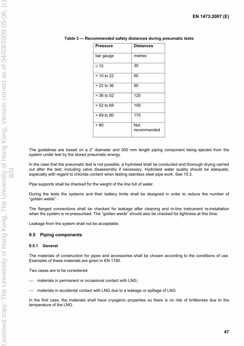
EN 1473:2007 (E)
47
Table 3 — Recommended safety distances during pneumatic tests
Pressure Distances
bar gauge metres
≤ 10 30
> 10 to 22 60
> 22 to 36 90
> 36 to 52 120
> 52 to 69 150
> 69 to 80 170
> 80 Not recommended
The guidelines are based on a 2” diameter and 300 mm length piping component being ejected from the system under test by the stored pneumatic energy.
In the case that the pneumatic test is not possible, a hydrotest shall be conducted and thorough drying carried out after the test; including valve disassembly if necessary. Hydrotest water quality should be adequate, especially with regard to chloride content when testing stainless steel pipe work. See 15.3.
Pipe supports shall be checked for the weight of the line full of water.
During the tests the systems and their battery limits shall be designed in order to reduce the number of “golden welds”.
The flanged connections shall be checked for leakage after cleaning and in-line instrument re-installation when the system is re-pressurised. The “golden welds” should also be checked for tightness at this time.
Leakage from the system shall not be acceptable.
9.5 Piping components
9.5.1 General
The materials of construction for pipes and accessories shall be chosen according to the conditions of use. Examples of these materials are given in EN 1160.
Two cases are to be considered:
materials in permanent or occasional contact with LNG;
materials in accidental contact with LNG due to a leakage or spillage of LNG.
In the first case, the materials shall have cryogenic properties so there is no risk of brittleness due to the temperature of the LNG.
Lice
nsed
cop
y: T
he U
nive
rsity
of H
ong
Kon
g, T
he U
nive
rsity
of H
ong
Kon
g, V
ersi
on c
orre
ct a
s of
04/
03/2
009
05:0
6, (
c)B
SI
EN 1473:2007 (E)
48
In the second case, according to the results of the hazard assessment (see 4.4.2.3), special precautions shall be taken, for example:
use of cryogenic materials;
insulation with a suitable material.
In order to improve fire resistance process pipe-work that can be exposed to fire or heat shall not be fabricated from material with a melting point lower than steel. The fire exposed piping could exist in areas where spilled hydrocarbon could collect or accumulate and be on fire, or subject to a jet fire, following an accident or a hydrocarbon release.
For LNG or cold gas pipes, arrangements shall be made to prevent the following:
any differential contractions sufficient to cause deformation, jamming of moving parts, alignment defects etc.;
icing up of components in contact with the atmosphere. If the phenomenon cannot be avoided, the weight of accumulated ice shall be considered for the calculation of supports.
Positive isolation shall be provided where it is necessary to protect personnel undertaking internal inspection or maintenance of equipment. This can be in the form of:
a removable spool piece;
a spectacle blind or spade and spacer.
9.5.2 Pipe
9.5.2.1 General
Piping shall be in compliance with recognised codes and standards.
9.5.2.2 Pipe joints
Joints between pipes made by welding shall be in accordance with the following specifications:
exclusive use of filler metals approved by the owner;
welding according to a procedure qualified according to EN ISO 15614-1;
use of welders and/or operators qualified according to EN 287-1;
inspection before, during and after welding in compliance with EN 473.
Welding of different pipe materials shall be made with special care especially with regard to thermal stresses arising from differential contraction and electrochemical corrosion.
Flange joints shall be limited to a minimum in particular for maintenance operations. If these types of junctions are used, special precautions shall be taken when the bolts are tightened. More particularly, for cryogenic services, precautions shall be taken to prevent leakage during cooldown, e.g. bolt pre-tensioning, spring washers.
PN designated flanges and gaskets shall be in accordance with EN 1092-1 and non-metallic flat gaskets shall be in accordance with EN 1514-1.
Lice
nsed
cop
y: T
he U
nive
rsity
of H
ong
Kon
g, T
he U
nive
rsity
of H
ong
Kon
g, V
ersi
on c
orre
ct a
s of
04/
03/2
009
05:0
6, (
c)B
SI
EN 1473:2007 (E)
49
Non-welded joints shall be tested in accordance with EN 12308.
9.5.2.3 Pipe supports
The support shall permit the movement of the pipe due to thermal contraction or expansion without exceeding allowable stresses. The support design shall suit this function and shall prevent any cold bridge between the pipe and the structure on which it is resting or from which it is hanging.
The design of the supports and related piping shall consider the vibrations and surge loads in the line.
9.5.2.4 Compensation of contractions due to cold
All piping systems shall be subject to stress analysis using recognised piping codes. Special measures shall be taken into account in order to absorb dimensional variations of pipes linked with changes of temperatures, e.g.:
expansion loops;
hinge type compensators capable of oscillating about its longitudinal axis (ca. 5°);
hinged systems.
It is recommended that bellows expansion joints be avoided.
Special care should be taken for small branch connections to headers to avoid any rupture or buckling of the main headers where these have thin walls, due to the application of external loads.
9.5.3 Flexible hoses
Flexible hoses may be used to make small temporary connections for the transfer of LNG and other cryogenic liquids such as refrigerant and liquid nitrogen, for example when emptying or filling road tankers of LNG or liquid nitrogen and they can also be used for transfer operations between small LNG carriers and LNG satellite plants. The use of flexible hoses shall be in accordance with the hazard assessment (see Clause 4).
Flexible hoses shall not exceed 15 m in length and 0,5 m³ in volume. Their design pressure shall be limited to PN 40.
Flexible hoses shall not be used for the routine transfer of LNG between large LNG carriers and shore at conventional LNG terminals.
Flexible hoses shall be designed in accordance with relevant codes and/or standards, such as EN 12434.
9.6 Valves
Valves shall be designed, manufactured and tested in accordance with EN 12567.
Cryogenic valves shall comply with the requirements of EN 12567. Cryogenic valves shall be capable of operating even in the presence of ice.
In-line split body valves are not recommended in cryogenic services.
Valves to be installed in cryogenic hydrocarbon and toxic systems are recommended to have butt-welded ends.
It is recommended that cryogenic and high temperature welded valves be designed to enable the maintenance of the internal components without removal of the valve body from the line.
Lice
nsed
cop
y: T
he U
nive
rsity
of H
ong
Kon
g, T
he U
nive
rsity
of H
ong
Kon
g, V
ersi
on c
orre
ct a
s of
04/
03/2
009
05:0
6, (
c)B
SI
EN 1473:2007 (E)
50
Valves in hydrocarbon service shall be fire safe according to EN ISO 10497.
The number of valves should be limited to reduce the potential for leakage. However consideration shall be given to the following:
requirements for sectional depressurisation of pipe and equipment systems;
safe isolation of LNG or any hazardous fluid sources or specific equipment or tankage;
limitation of the volume of LNG or any hazardous fluid spilt in the event of a leak.
Emergency shut down (ESD) valves for equipment shall be located as close as possible to the equipment.
ESD valves should not be used as a part of process control system. ESD valves shall be fail-safe with pneumatic or hydraulic actuators. Preference is given to failsafe position spring return actuators. However, if this type is not possible, local accumulators sized for 3 single operations shall be provided. Actuators and aboveground connecting devices and cables shall be fire proofed (e.g. at 1 100 °C during the time needed to implement ESD, see 14.3).
The ESD valves stroke time shall be compatible with the assumptions made during the hazard assessment (see Clause 4). The designer shall ensure that any actions, for example due to hydraulic pressure hammer (surges) on the tank or equipment nozzles caused by closing of the emergency shut down (ESD) valves shall be kept in acceptable limits.
Cryogenic extended bonnet valves shall be installed with the stem in the vertical upwards position or within 45° of vertical. Before installation in any other position, it shall be verified and tested to show in the foreseen position that the valve design does not present any risk of leakage or seizure. This requirement does not apply to small bore instrument isolating valves.
9.7 Relief valves
Relief valves should be normally installed un-insulated.
Relief valves shall be sized in accordance with the recommendations of [3] and [10] including the formulae for heat input from fires.
Thermal relief valves for the protection of equipment, piping and hoses from over-pressure resulting from ambient heat input to blocked in LNG or other light hydrocarbon liquids shall be installed. They are required where the pressure of the fluid at the maximum ambient temperature including that obtained as the result of solar radiation could exceed the design pressure, at least in the following locations:
any volume of piping or equipment containing liquid within the section limits of the process plant;
any volume of piping or equipment capable of isolation in particular all of sections pipe between two valves where LNG or cold gas risks being trapped in storage and (un)loading areas.
The discharge of the relief valves is dealt with as defined in 4.5.2.1 c).
When relief valves could be isolated from the equipment and/or system that they are protecting special provisions shall be implemented to ensure that the pressure in the equipment and/or system shall be continuously monitored and controlled in case of isolation valve closure. These provisions could be:
interlocked valves in case of several relief valves;
locked or sealed valves with safety management system;
special working procedure under safety permit system.
Lice
nsed
cop
y: T
he U
nive
rsity
of H
ong
Kon
g, T
he U
nive
rsity
of H
ong
Kon
g, V
ersi
on c
orre
ct a
s of
04/
03/2
009
05:0
6, (
c)B
SI
EN 1473:2007 (E)
51
9.8 Thermal insulation
9.8.1 General
The quality and type of insulation materials shall be determined in accordance with the following requirements:
their degree of flammability and gas absorption;
sensitivity of the insulation materials to moisture;
large temperature gradients;
low temperatures.
The features of the insulating materials shall be provided in accordance with the relevant codes and/or standards.
Low chloride content insulation shall be used to avoid corrosion of stainless steel.
9.8.2 Piping insulation
Piping systems shall be insulated, where required, to:
minimise energy consumption;
provide protection against condensation and/or frost;
protect employees.
Insulation is provided by applying:
an insulating material;
a vapour barrier, for cold piping, to prevent ingress of moist air leading to condensation and freezing of water vapour;
mechanical/weather protection, which can also ensure fire resistance where required according to 9.8.3.
When insulation is put into place, precautions shall be taken at:
flanges, in order to provide enough space for the bolts to be satisfactorily tightened and removed;
moving parts of piping;
pipe supports and hangers.
Insulation should not to be put into place before proof test of the piping.
Consideration should be given to shop pre-insulated pipe work.
9.8.3 Fire behaviour
When designing multi component insulation systems the fire behaviour of all components, including mastic, sealants, vapour barriers and adhesives, shall be proved and documented to ensure that the system will not cause the fire to spread and any vapours emitted shall not cause an unacceptable risk of toxicity.
Lice
nsed
cop
y: T
he U
nive
rsity
of H
ong
Kon
g, T
he U
nive
rsity
of H
ong
Kon
g, V
ersi
on c
orre
ct a
s of
04/
03/2
009
05:0
6, (
c)B
SI
EN 1473:2007 (E)
52
9.8.4 Gas absorption
For obvious safety reasons, porous insulation products likely to absorb gaseous methane shall be avoided.
9.8.5 Moisture resistance
Moisture present in insulation systems very quickly impairs the performance of the insulation materials. For example, 1 % moisture in volume contained in an insulation material reduces its thermal efficiency by 20 % to 30 %.
Water can penetrate into an insulation material in 2 different ways:
either in the liquid state;
or as water vapour which condenses within the insulation material.
Some insulation materials are waterproof to a certain extent, but most of them are permeable to gases and thus to water vapour.
In order to avoid water vapour ingress, an efficient vapour barrier shall be provided and placed around the insulation material, except when the insulation is itself water vapour tight.
9.8.6 Differential movements
A water vapour tight insulation system should be achieved. It shall be designed to remain gas tight even after undergoing the anticipated differential movements between the pipe and the various products that make up the insulation system (including the vapour barrier(s), coatings, cell fillers, metal jackets).
The joints, mostly contraction joints, shall be designed to resist differential movement cycles in relation to both internal and external temperature variations.
The thickness of each insulation layer shall, if necessary, be limited in order to reduce the shear stresses due to the temperature gradient between the warm and the cold side, to a value less than the maximum acceptable shear stress, whilst taking into account a safety factor.
9.8.7 Thickness determination
Thickness should be calculated according to EN ISO 12241 taking into account the following requirements:
safety (sizing of the over-pressure valves);
boil-off limitation, this limitation is determined for various reasons:
cost;
sizing of the gas treatment equipment (re condensers, disposal flares/vents);
control of surface condensation.
When requested by EN ISO 12241, more precise methods should be used to accurately predict heat gain and insulation surface temperature, see for example [20] and [21].
The consequences of condensation are for example:
in temperate or cold zones, outside surface condensation can turn into ice, which can lead to premature ageing of the vapour barriers or protective coatings;
Lice
nsed
cop
y: T
he U
nive
rsity
of H
ong
Kon
g, T
he U
nive
rsity
of H
ong
Kon
g, V
ersi
on c
orre
ct a
s of
04/
03/2
009
05:0
6, (
c)B
SI
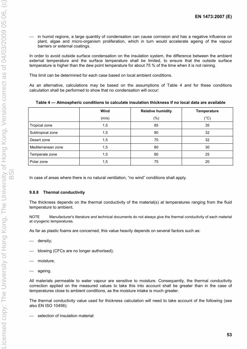
EN 1473:2007 (E)
53
in humid regions, a large quantity of condensation can cause corrosion and has a negative influence on plant, algae and micro-organism proliferation, which in turn would accelerate ageing of the vapour barriers or external coatings.
In order to avoid outside surface condensation on the insulation system, the difference between the ambient external temperature and the surface temperature shall be limited, to ensure that the outside surface temperature is higher than the dew point temperature for about 75 % of the time when it is not raining.
This limit can be determined for each case based on local ambient conditions.
As an alternative, calculations may be based on the assumptions of Table 4 and for these conditions calculation shall be performed to show that no condensation will occur:
Table 4 — Atmospheric conditions to calculate insulation thickness if no local data are available
Wind Relative humidity Temperature
(m/s) (%) (°C)
Tropical zone 1,5 85 35
Subtropical zone 1,5 80 32
Desert zone 1,5 70 32
Mediterranean zone 1,5 80 30
Temperate zone 1,5 80 25
Polar zone 1,5 75 20
In case of areas where there is no natural ventilation, “no wind” conditions shall apply.
9.8.8 Thermal conductivity
The thickness depends on the thermal conductivity of the material(s) at temperatures ranging from the fluid temperature to ambient.
NOTE Manufacturer's literature and technical documents do not always give the thermal conductivity of each material at cryogenic temperatures.
As far as plastic foams are concerned, this value heavily depends on several factors such as:
density;
blowing (CFCs are no longer authorised);
moisture;
ageing.
All materials permeable to water vapour are sensitive to moisture. Consequently, the thermal conductivity correction applied on the measured values to take this into account shall be greater than in the case of temperatures close to ambient conditions, as the moisture intake is much greater.
The thermal conductivity value used for thickness calculation will need to take account of the following (see also EN ISO 10456):
selection of insulation material:
Lice
nsed
cop
y: T
he U
nive
rsity
of H
ong
Kon
g, T
he U
nive
rsity
of H
ong
Kon
g, V
ersi
on c
orre
ct a
s of
04/
03/2
009
05:0
6, (
c)B
SI
EN 1473:2007 (E)
54
water vapour tightness;
dimensional changes at cryogenic temperatures, especially in expansion loops;
deterioration;
selection and application of the vapour barrier:
film or coatings;
single layer on the outside or multiple layers;
longitudinal partitioning or not;
quality of the products and source of supply;
reinforcement or not;
risks of deterioration and, if the equipment has been damaged, study of the risk of local or widespread damage;
resistance to maintenance activity;
climatic conditions:
dry, temperate or tropical zones;
risk of outside thaw;
risk of mechanical damage:
foot traffic on piping or equipment;
design and quality of critical points such as tees, elbows, supports, flanges, valves etc.;
maintenance quality;
qualification of the insulation contractor:
quality of workmanship;
jobsite protection in case of bad weather;
operating temperature;
variable or constant service temperature;
job complexity:
number of elbows, connections, valves etc.
9.9 Pipe rack/pipe way
Pipes are arranged either on a pipe-rack or pipe-way. The main and auxiliary process systems shall be routed in the open air as much as possible so as to avoid any confinement of combustible gas.
Lice
nsed
cop
y: T
he U
nive
rsity
of H
ong
Kon
g, T
he U
nive
rsity
of H
ong
Kon
g, V
ersi
on c
orre
ct a
s of
04/
03/2
009
05:0
6, (
c)B
SI
EN 1473:2007 (E)
55
Supports shall be sized so as to resist the cases of actions defined in Annex F.
Supports shall be protected against the exposure to fire (see 13.2.1) and/or a leak of LNG or cold gas (see 13.2.2.) if required by the hazard assessment.
The ground below the pipe racks shall be suitably graded and sloped to avoid pooling of rain water and spilled hydrocarbons.
9.10 Corrosion
Piping systems shall be designed so as to prevent any leak due to corrosion or pitting during the lifetime of the plant. The choice of materials and corrosion allowances shall be made according to the operating and environmental conditions (presence of chlorides or sulphurous or nitrogenous compounds).
Special measures shall be taken such as cathodic protection and the application of corrosion-proof coatings adapted to the risk involved (see 12.3 and 16.1).
10 Reception/send out of natural gas
10.1 Metering
10.1.1 Background
Flow metering can be required for fiscal, custody transfer or material balance purposes. The accuracy of the metering systems shall be sufficient for the purpose.
10.1.2 Flow metering
Flow metering shall be conducted in accordance with EN 1776.
Turbine flow meters should be protected against bursting of the primary filter.
10.2 Gas quality
10.2.1 Background
The gas quality sent out to network from a receiving terminal shall meet the local requirements in particular concerning:
total H2S content;
the average calorific value and the Wobbe Index range of the gas.
All domestic gas supplied can be odorised (see 10.3 and Annex N).
Gas arriving in an LNG export plant may require that certain contaminants be removed before the gas can be liquefied (refer 12.6).
10.2.2 Gas quality adjustment
Gas leaving the LNG installations shall comply with pipe gas quality parameters such as Wobbe Index, calorific value and, if required, odour intensity.
Lice
nsed
cop
y: T
he U
nive
rsity
of H
ong
Kon
g, T
he U
nive
rsity
of H
ong
Kon
g, V
ersi
on c
orre
ct a
s of
04/
03/2
009
05:0
6, (
c)B
SI
EN 1473:2007 (E)
56
Accurate analysis of the existing streams is required to ensure that these parameters are being met. There shall be on-line monitoring and a means of correcting the gas quality parameters, should it be anticipated that it could go out of the required range.
This correction can be carried out by the addition of propane or butane to low calorific value streams (such as boil-off) or air/nitrogen to high Wobbe Index streams (such as "aged" LNG).
NOTE It can be more cost effective to produce an LNG of a quality that will not go out of the required range within the normal storage period than to adjust the gas quality at the send out.
Accurate metering, analysis and control systems are required to ensure corrective actions can be taken rapidly and smoothly.
10.3 Odourising
Odourisation storage and injection equipment may be provided at installations where required either by local regulation or at the client's request for gas entering the supply system.
Specifications for the characteristics of odourants, construction and operation of odourisation installations shall be in accordance with relevant standards. If no standard exists, odourisation installations may be designed in accordance with Annex N.
11 Boil off recovery and treatment plants
11.1 General
Boil off recovery plants shall be installed in order to collect LNG boil off due to heat in leak and flash present in the feed when filling tanks or when loading LNG carriers.
The vapours shall be safely disposed of through re-liquefaction, used as fuel gas, vapour to tankers (terminals only), re-compressed to gas network or as a last resort flared or released to the atmosphere.
Precautions shall be taken to prevent any penetration of air into the boil off recovery systems.
The boil off recovery plants generally comprise:
boil off collection pipe-work;
system(s) of gas transfer to/ from the tanker(s);
boil off gas compressors;
re-condensers and or re-liquefaction system.
11.2 Boil off collection system
This system shall be designed so that no direct emission of cold gas into the atmosphere can arise during normal operation.
The system shall be designed at least for the following:
boil off of tanks and all receivers containing LNG;
degassing systems of piping and equipment containing LNG;
gas displaced from a LNG carrier during loading.
Lice
nsed
cop
y: T
he U
nive
rsity
of H
ong
Kon
g, T
he U
nive
rsity
of H
ong
Kon
g, V
ersi
on c
orre
ct a
s of
04/
03/2
009
05:0
6, (
c)B
SI
EN 1473:2007 (E)
57
The boil off system shall be designed applying the same sizing rules as those defined in Clause 9. The constituent materials shall have cryogenic properties (the boil off gases can reach temperatures close to – 160 °C). The lagging of pipes shall be of the same thickness as that of low pressure LNG pipes of the same diameter, unless the boil off is routed to the flare/vent system (see 11.6).
The maximum working pressure of the boil off system shall be compatible with the maximum pressure capable of arising at the time of the opening of the degassing system or be equipped with a double pressure limiting device.
Valved drain points, connected to the drain system shall be installed at low points of all main lines or flare lines (upstream of flare knock out drum).
The connections between the tanks and boil off collection system are recommended with valving and instrumentation enabling:
isolation of a tank;
reduction of the pressure of one tank, without altering the pressure of the others;
the measurement of any boil off rate reduction each tank, as part of the strategy for roll-over prevention as described in 6.9.1.
11.3 System of gas return to tanker(s) or to export terminal
The system connects the boil off collection system to the vapour return arm of the jetty.
It shall provide for the transfer of gas from the tanks to the LNG carrier or reverse, in order to compensate the volume of liquid displaced during unloading or loading, and the collection of boil off from the tanker while it stays at the jetty.
If necessary a blower or booster compressor can be used.
The pipes shall have the same characteristics as those of the collection systems.
11.4 Boil off gas recovery
The boil off gas can be:
re-liquefied;
re-condensed in the LNG send out prior to vaporisation;
used as fuel gas;
re-compressed and sent to gas network.
In receiving terminals, the boil off gas is usually compressed and cooled, then introduced into a re-condenser where it is re-liquefied in contact with all or part of the send out flow of low pressure LNG.
The re-condenser shall be designed in accordance with EN 13445 and shall be made up of materials with cryogenic characteristics. It shall be insulated.
11.5 Gas compressor
The compressors shall be equipped with systems to limit the pressure downstream to avoid the risk of exceeding the maximum design pressure of the equipment that is installed down stream.
Lice
nsed
cop
y: T
he U
nive
rsity
of H
ong
Kon
g, T
he U
nive
rsity
of H
ong
Kon
g, V
ersi
on c
orre
ct a
s of
04/
03/2
009
05:0
6, (
c)B
SI
EN 1473:2007 (E)
58
Gas compressors shall be equipped with a shut down sequence either manually or automatically initiated which enables them to be isolated in the event of serious damage.
Adequate ventilation shall be provided in any space of a gas compressor, such as the crankcase, that could become over-pressurised. Vents shall be led to a safe area.
11.6 Flare/vent
11.6.1 General
The facilities shall be fitted with a flare or vent system(s).
The flare or vent has two conditions: the normal and accidental flows.
The normal flow rate results from all operating configuration modes, either steady or transient, nominal or downgraded, but staying within the facility initial design intent.
The accidental flow rate is the highest flow rate that results from an uncontrolled and/or unplanned event which may occur during operation. It is the sum of the normal flow rate and the highest total flow related to other possible uncontrolled /unplanned scenarios that may occur simultaneously.
The hazard assessment shall determine the combination(s) of events which may actually occur simultaneously without double jeopardy (simultaneous unrelated events).
If for any reason, some downgraded situations are not included in the “normal flow rate” (e.g. commissioning, cooling down of warm LNG tanker from dry docking, etc) the designer shall check that the related flow rate added to the normal flow rate is lower than the accidental flow rate.
The conditions that cause these flows vary significantly between LNG import and export terminals.
The layout of the flare/vent shall respect the radiation flux levels defined in Table A.3 and where practicable shall be chosen according to the prevailing wind in order to minimise the risk of the flame being reached by a flammable gas cloud (flare) and flammable gas cloud reaching an ignition source (vent).
11.6.2 For import terminal
The facility is designed around the premise of no continuous flaring or venting, 4.2.4. Under accidental conditions a flare or vent shall safely dispose of all envisaged flows. The two indicative flow-rates, normal and accidental, are identified and defined as:
the normal flow rate which is the sum of the flow rates defined in 6.7.2, excluding roll-over, and the boil off gas due to heat input of all receivers containing LNG (pipes, drain drums etc.). This flow rate is intermittent by definition;
the accidental flow rate, which is the greater of the two following combinations:
normal flow rate and flow rate at the outlet of the safety relief valve of one vaporiser as defined in 8.1.6, if it is connected to the same flare/vent system;
normal flow rate and flow rate at the outlet of the relief valves of one tank as defined in 6.7.3, if they are connected to the same flare/vent system.
The flare/vent shall be sized for the maximum gas flow rate that can be envisaged, i.e. accidental flow rate. If the relief valves of tanks and vaporisers are not connected to the flare/vent system, alternative flow conditions will form the basis of the accidental flow rate. This typically can include one or a combination of the following:
normal flow rate, 6.7.2, excluding roll-over;
Lice
nsed
cop
y: T
he U
nive
rsity
of H
ong
Kon
g, T
he U
nive
rsity
of H
ong
Kon
g, V
ersi
on c
orre
ct a
s of
04/
03/2
009
05:0
6, (
c)B
SI
EN 1473:2007 (E)
59
emergency loads such as depressurising loads;
one or more abnormal operating loads such as:
unloading of an LNG carrier without returning gas displaced from the storage tank to the carrier for some reason;
cool down of the LNG carrier tanks;
off-spec gas that cannot be recovered and has to be flared/vented.
High pressure gas release may be routed to a separate flare/vent, for example the flow rate from the relief valve of one vaporiser which for the situation is considered to be the accidental flow rate.
11.6.3 For export terminal
The events creating the accidental loads on the flare/vent for a LNG export terminal are more numerous than those for an import terminal. These events shall be tabulated in a relief and de-pressurising summary to establish the accidental flare/vent load.
Relief loads arising from control valve failures and blocked flow outlets are often defining the accidental load cases.
Normal loads arise from any event that is under the control of the operator plus loads due to heat leakages and loading operation.
Often a separate low pressure flare is provided for the storage and loading area.
Export terminal often have ”wet” and “dry” flare systems.
Wet system carries gas with significant water content.
Dry flare systems are for cryogenic quality gas.
Acid gas flare systems are sometimes provided.
12 Auxiliary circuits and buildings
12.1 Electrical equipment
12.1.1 General requirements
All electrical equipment, instrumentation equipment and installations located in hazardous area (see 4.5.2.1 b) shall be in accordance with the EN 60079 / IEC 60079 series according to Clause 2.
A study should be undertaken to define the required IP classification for electrical equipment as specified EN 60529 and EN 60034-5.
12.1.2 Main electric power supply
The plant may either import electrical power from the local grid or generate its own power, or a combination of the two cases.
If power is imported from the local grid, it is preferred that there are two independent incoming power lines to maintain supply integrity. The power supply to the plant system should be reviewed to identify any point where
Lice
nsed
cop
y: T
he U
nive
rsity
of H
ong
Kon
g, T
he U
nive
rsity
of H
ong
Kon
g, V
ersi
on c
orre
ct a
s of
04/
03/2
009
05:0
6, (
c)B
SI
EN 1473:2007 (E)
60
the independent lines may join or where there is a risk to both independent supplies from a common mode failure.
The incoming lines shall each be rated to:
a) carry the full load of the LNG plant;
b) enable at any time the starting of the largest motor on the plant without excessive voltage drops at the main bus-bars or the other motor terminals.
Grid transmission voltage is stepped down to site voltage at the entry to the plant by power transformers. The transformers should each be capable of supplying the full load of the plant.
Where the plant generates its own power without connection to a grid, the power source shall have spare capacity to allow one power generating unit to be off line and still maintain the necessary power to the plant.
Where the plant generates its own power there shall be provision to start the plant up from complete shutdown. This is often called a “black start”. Start up procedures shall consider that the normal fuel to the power generation units may be unavailable at a black start.
The owner should consider if a stability analysis of the electrical system is required, particularly if variable speed drives are used. The effect of a short duration voltage dip should be considered.
12.1.3 Emergency Power Supply (EPS)
An Emergency Power Supply shall be provided. It shall be designed to ensure, in case of failure of the main electrical power supply, all the vital functions for the safety of staff and the facility are maintained.
The capacity of the emergency electrical power shall be adequate to bring the plant to a controlled and orderly shutdown state in the event of total loss of power supply. The designer shall identify all loads on the emergency generator.
As a minimum it shall:
provide power for one in-tank pump;
ensure the LNG carrier can cease a transfer operation and leave the berth if required;
maintain all safety critical; loads (process instrumentation, fire and safety equipment and associated systems, MOV’s (Mechanically Operated Valves), telecoms, warning lights, essential lighting etc.);
start and run the firewater jockey pumps;
maintain sufficient power to the electric base heating (if fitted) of the LNG storage tanks;
provide an instrument air and/or nitrogen supply if required for safety functions.
Emergency generator shall have a minimum of 24 h fuel supply in the “day tank” sited at the generator and be capable of being refuelled when running.
The designer should establish if main equipment items need a power supply to ensure safe shut and cool down.
12.1.4 Uninterruptible Power Supply (UPS)
An Uninterruptible Power Supply shall be provided.
Lice
nsed
cop
y: T
he U
nive
rsity
of H
ong
Kon
g, T
he U
nive
rsity
of H
ong
Kon
g, V
ersi
on c
orre
ct a
s of
04/
03/2
009
05:0
6, (
c)B
SI
EN 1473:2007 (E)
61
It shall provide power to critical control and safety systems so that the plant may be kept in a safe condition for a minimum of 60 min.
12.1.5 Lighting
Lighting shall be provided in plant areas where safe access and safe conditions for work activities is required at night.
An emergency battery lighting system shall be provided to allow the safe escape of staff from accessible areas of the plant in the event of a power and essential lighting failure, or an emergency situation.
12.2 Lightning and earthing
12.2.1 Lightning protection
Lightning protection shall be in accordance with recognised IEC standards and/or codes (e.g. [17] and [27]).
The following installations shall be, as a minimum, protected against lightning:
tanks and their accessories;
marine transfer arms;
buildings;
flares and vents.
12.2.2 Earthing circuit
Earthing shall be in accordance with IEC standards, in particular IEC 60364-5-54.
The design shall ensure personnel protection and avoid potential difference between metallic components and the possibility of spark generation in hazardous areas.
12.3 Cathodic protection
All underground/subsea metallic parts should be protected where necessary against corrosion using appropriate coating and/or cathodic protection in accordance with the relevant codes and/or standards.
12.4 Warning lights
Tanks and other elevated structures shall be fitted with warning lights to comply with air and safety navigation regulations.
The jetty shall have navigational lights in accordance with local marine regulations.
12.5 Sea water supply
12.5.1 Materials
Materials shall be carefully selected in terms of fluids and the site environment.
Particular attention shall be paid to the compatibility of materials to avoid any galvanic corrosion.
Lice
nsed
cop
y: T
he U
nive
rsity
of H
ong
Kon
g, T
he U
nive
rsity
of H
ong
Kon
g, V
ersi
on c
orre
ct a
s of
04/
03/2
009
05:0
6, (
c)B
SI
EN 1473:2007 (E)
62
12.5.2 Water pumping
It is recommended that the number and sizing of cooling water pumps or seawater pumps is such that unavailability of a pump of the highest rated capacity will not prevent the water requirements of exchangers and cooling services from being met.
The design of the seawater intake often requires detailed study to ensure that the filtration and hydraulic requirements of the seawater pumps are correctly addressed.
Filtration shall be provided in accordance with pump and related equipment manufacturer requirements.
Water circuits are susceptible to internal corrosion and/or fouling by natural organisms. Measures to prevent this should be fitted if required. The discharge of water treated with anti- corrosion and anti-fouling chemicals shall be in compliance with the discharge permit(s) for the plant (see 4.2.1, 4.2.2 and 4.2.3). The discharge temperature of the water shall be in compliance with the discharge permit(s).
12.6 Gas contaminant removal plant
Some liquefaction plants require gas treatment to remove gas contaminants such as mercury, sulphur, carbon dioxide, mercaptans and aromatics from the incoming gas.
Facilities and procedures shall be in place for the secure handling, storage and recycling or disposal of these materials and their removal media if required.
Material Safety Data Sheets for the absorption and reactant media shall be provided and shall state specific requirements for safe disposal or recycling of the material in a “used” or “spent” condition.
12.7 Instrument air
When instrument air is used its supply shall be reliable. This shall usually mean the provision of at least two air compressors each capable of supplying the total requirement.
Instrument air supplies shall be guaranteed for the time interval needed to put the plant in a safe condition on failure of the main power source. This shall be for a minimum of 15 min. This may be achieved by for example, providing air receivers to provide the necessary storage.
If the instrument air compressors are electrically driven, at least one, capable of supplying the total requirements, should have its power supplied from the emergency power supply.
The air shall be dried to a dew point compatible with the plant minimum ambient temperature conditions. The dew point shall be at least − 30 °C and 5 °C below ambient temperature (both referenced to atmospheric pressure).
The instrument air system is to be independent of the plant air or service air systems.
12.8 Fuel (utility) gas
An LNG plant may be equipped with a fuel gas system. The main applications depending on the type of the plant are the following:
gas fired vaporisers;
gas turbine or gas engine driven compressors and generators;
steam boilers and process heaters;
Lice
nsed
cop
y: T
he U
nive
rsity
of H
ong
Kon
g, T
he U
nive
rsity
of H
ong
Kon
g, V
ersi
on c
orre
ct a
s of
04/
03/2
009
05:0
6, (
c)B
SI
EN 1473:2007 (E)
63
tank safety, as vacuum breaker gas;
flare pilot gas and purge.
Fuel gas used within the plant shall not be odourised. Leak detection shall be provided by the gas detection system as 13.4.
12.9 Nitrogen system
Nitrogen can be produced on site or delivered as liquid nitrogen by road or rail.
Certain process conditions such as molecular sieve regeneration or for injection as a component in a make-up stream may require that a high quality nitrogen supply is used.
The nitrogen is used mainly for:
gas treatment (calorific value adjustment);
pressurisation;
equipment, LNG tank insulation space and piping purging;
drying and inerting;
rapid extinction of flares and vents;
cooling;
refrigerant cycle make up.
The liquefied nitrogen pipe-work shall be designed with cryogenic materials in accordance with recognised local codes and/or standards, examples of acceptable materials are given in EN 1160.
Cross connection between gaseous nitrogen systems and air systems is not permitted for safety reasons.
12.10 Buildings
Building design and construction shall comply with the requirements of hazard assessment (see 4.4.2.5), the following standards and with local regulations, especially for seismic design:
EN 1992-1-1;
EN 1993-1-1;
EN 1994-1-1;
EN 1998-1.
For the electrical installations of buildings see also [11].
Where identified in the hazard assessment, buildings shall be pressurised (see IEC 60079-13 guidelines). Forced ventilation air intakes for buildings shall be fitted with gas detectors to shut down ventilator fans and inhibit start up to avoid any risk of sending gas into the building.
The permanently manned control rooms shall be designed to enable occupation for sufficient time for the emergency procedures to be put into effect and to permit evacuation to a safe location. The heating,
Lice
nsed
cop
y: T
he U
nive
rsity
of H
ong
Kon
g, T
he U
nive
rsity
of H
ong
Kon
g, V
ersi
on c
orre
ct a
s of
04/
03/2
009
05:0
6, (
c)B
SI
EN 1473:2007 (E)
64
ventilation and air conditioning system shall be designed to suit the possible received radiation flux (see 4.4.2.5 and Annex A).
Where buildings are designed for blast over-pressure the design shall consider the risk to personnel caused by the blast wave entering the building through ventilation inlets and outlets.
13 Hazard management
13.1 Inherent safety
13.1.1 Provision for minimum safety spacing
The safety spacing shall be calculated considering possible fire radiation levels and gas dispersion zones. The allowable exposure levels are specified in Annex A. Safety distances between LNG tanks, process units, control rooms etc. shall comply with the minimum requirements to achieve these threshold values.
13.1.2 LNG Plant layout
The siting of an LNG plant with respect to the surroundings shall be covered by a site location assessment, see 4.3.2.5.
The following clause concerning the plant layout uses the terms “hazardous areas” and “hazard affected areas”. In this context the hazard affected areas are those areas where those events described in 4.4 could arise. The term hazardous area applies specifically to those areas that are defined in 4.5.2.1 b).
The LNG plant shall be laid out to provide safe access for construction, operation, maintenance, emergency action and comply with the layout requirements identified in the Hazard Assessment according to 4.4.2.
Separation distances shall take into account, in particular:
radiation flux levels;
lower flammability limit contours;
noise;
blast effects.
The prevailing wind direction shall be considered in LNG plant layout. Where practicable, buildings and ignition sources should not be downwind of possible accidental and planned releases of flammable materials. They shall be located outside hazardous areas.
Plant buildings should be sited outside the hazard affected areas or designed to resist these accident scenarios. The building’s level of occupancy shall also be part of this evaluation.
The central control room shall be located outside process areas and should be outside hazardous areas. Furthermore, it shall be designed to operate during and resist those accident scenarios that have been identified in the Hazard Assessment.
For all equipment, such as air compressors, fired process equipment, gas turbines, diesel driven fire water pumps and emergency generators, the air intake shall be located outside zone 0 and 1 areas. Air intakes shall be fitted with gas detection which will trip the equipment.
The spacing between two adjacent tanks shall be the result of a detailed hazard assessment. This shall be a minimum of half the diameter of the secondary container of the larger tank.
Lice
nsed
cop
y: T
he U
nive
rsity
of H
ong
Kon
g, T
he U
nive
rsity
of H
ong
Kon
g, V
ersi
on c
orre
ct a
s of
04/
03/2
009
05:0
6, (
c)B
SI
EN 1473:2007 (E)
65
Additional guidance on plant layout is given in the following reference [8], [9] and [48].
13.1.3 Escape routes
Escape routes shall be provided for all plant areas where a hazard to personnel may arise. Escape routes shall be laid out to encourage an intuitive response from personnel to lead them from high hazard areas to low hazard areas and shall consider that there may be some panic in an emergency situation. The design shall take into account the fact that when LNG is spilled a “fog” is created by condensation of atmospheric humidity.
13.1.4 Confinement
Confined or partially confined zones shall be avoided as far as possible, in particular:
gas and LNG pipe-work shall not be situated in enclosed culverts when it is possible to avoid this for example where road bridges cross pipe ways;
the space situated under the base slab of raised tanks, if any, shall be sufficiently high to allow air to circulate;
where cable culverts are used they shall be filled with compacted sand and covered with flat slabs featuring ventilation holes to minimise the possibility of flammable gases travelling along the culverts through voids above the sand. As the sand settles the slabs will sink. They can be restored to their original elevation by adding sand.
13.1.5 Direct accessibility to valves and equipment
This is achieved by providing in the plant all the required safe accesses, paths, staircases (/ladders) and platforms, as required by the layout review(s) 4.5.3.
The road system should be developed to provide a direct access for the fire fighting trucks and other emergency response vehicles.
13.1.6 Selection of appropriate electrical components according to the classified area
Electrical equipment to be installed in hazardous areas will be qualified in accordance with EN 60079 / IEC 60079 series according to Clause 2.
Availability of required certificates shall be carefully checked on an individual basis.
13.1.7 Spillage collection, including paving in hazardous area
Restricting the extent of a potential leak is achieved by:
limiting the volume of the possible accidental spills;
containing these spills within defined impounding and spill collection areas, to prevent their spreading to other areas of the plant or outside the plant boundary and minimising the vapour cloud dispersion distance;
making provision to properly remove rainwater whilst LNG spill will be contained in the collecting systems and will not ingress into drains or other water courses;
controlling leaks and spillage.
Where dispersion calculations show that a leak can escalate to a more serious incident fixed leak detection systems with advisory or executive action to stop the leak source, are required to isolate sections of plant and to shutdown sources of ignition.
Lice
nsed
cop
y: T
he U
nive
rsity
of H
ong
Kon
g, T
he U
nive
rsity
of H
ong
Kon
g, V
ersi
on c
orre
ct a
s of
04/
03/2
009
05:0
6, (
c)B
SI
EN 1473:2007 (E)
66
The design of impounding basins shall be such that flammable fluids cannot enter the surface water drainage system. Spill detection devices and means to control the evaporation rate (e.g. foam generation see 13.6.5) should be provided. These channels and the impounding basin may be lined with an insulating layer to limit evaporation (see EN 12066).
Separation systems relying on the differential densities of water and LNG are not acceptable.
13.1.8 Retention systems in process and transfer areas
Liquid spills within LNG process and transfer areas shall be confined within a spill collection area and shall be drained to an impounding basin.
Subject to the results of risk analysis, the impounding basin may be located in the vicinity of, or remote from, the spill collection area. The spill collection area and the impounding basin shall be connected by open channel.
For process areas, the spill collection system or impounding basin capacity shall be at least 110 % of the total liquid inventory of the largest equipment item and related piping and other equipment that can drain through this item. Flash may be considered for capacity calculation.
At transfer areas and in the interconnecting pipe-work, where there is a potential for leaks (valves, equipment or instruments), the impounding basin capacity shall be determined by risk analysis considering potential leak sources, flow rates, detection systems, manning levels and response times.
13.2 Passive protection
13.2.1 Fire proofing
Fire proofing shall be used to protect equipment, typically: ESD valves, safety critical control equipment, vessels containing quantities of liquid hydrocarbon and structural supports, which on failure would escalation the incident and/or endanger the activities of emergency response personnel. Equipment which can receive thermal radiation, in excess of that defined in Annex A, for a sufficient period to cause failure shall be provided with fire proofing protection. The fire proofing shall provide protection for the duration of the hazard event but shall as a minimum provide 90 min protection.
Fire protection in the form of insulation or water deluge shall be provided for pressure vessels, which can receive thermal radiation fluxes in excess of that defined in Annex A, to prevent such vessels failing and releasing superheated liquid, which can result in a BLEVE, (see EN 1160).
It shall be recognised that pressure vessels subject to radiation from a major incident such as an LNG tank fire shall require protection for much more than 90 min. Protection for long duration incidents may not be achieved by insulation and a water deluge system is required.
The calculation of water deluge, insulation for fire protection of structures, etc. as protection against fires shall be performed for the fluid which gives rise to the highest radiation flux.
Fire proofing can be provided by:
preformed or sprayed concrete;
insulation materials made of mineral fibre, ceramic, calcium silicate or cellular glass;
intumescent coatings.
Fire proofing shall be designed and executed in accordance with the appropriate standards (see [7] and [31]).
Lice
nsed
cop
y: T
he U
nive
rsity
of H
ong
Kon
g, T
he U
nive
rsity
of H
ong
Kon
g, V
ersi
on c
orre
ct a
s of
04/
03/2
009
05:0
6, (
c)B
SI
EN 1473:2007 (E)
67
13.2.2 Embrittlement protection
The effect of low temperature fluid spills on adjacent plant, equipment and structural steel shall be assessed and measures taken to prevent incident escalation and/or endangerment of emergency response personnel, through suitable selection of materials of construction or by embrittlement protection.
Such protection shall be achieved by an appropriate material selection (concrete, stainless steel etc.) or by a insulating with material that will protect the equipment and structural supports from cold shock. Insulation shall be designed and installed in accordance with appropriate standards and provision taken to protect outer surfaces from wear and tear.
Equipment and structural support elements should be protected in such a way that their function and form are not adversely affected during the plant operation.
13.3 Security
The security should be covered by:
Anti-intrusion
The anti-intrusion system should be installed along the fences to monitor undesired ingress in the plant.
Access control
An access control system shall be installed in order to control the access to the various areas of the plant.
It may include badge readers, intercom, door contacts and anti-intrusion sensors.
The access control system will consider the different access levels (control rooms, process areas, general facilities etc).
The security control system should be linked to the CCTV to allow remote monitoring.
13.4 Incident detection and signalling
Systems shall be provided to detect possible accidental events, which could occur in the plant.
The arrangement of detectors shall be such as to always provide redundancy and to prevent false and spurious alarms. Voting technique arrangement may be used.
Events may include:
Earthquake
Where applicable seismic acceleration monitoring shall be provided, giving signals to automatically initiate the plant shutdown when the earthquake reaches a pre-defined level. This pre-defined level is chosen by the operator.
LNG spillage, gas leakage, flame and smoke
These detection systems are intended to rapidly and reliably detect any LNG spillage or flammable gas leakage and any fire condition in the plant.
Continuously operating detection systems shall be installed at every location, outdoors and indoors, where leaks are credible.
The following detection devices may be provided:
Lice
nsed
cop
y: T
he U
nive
rsity
of H
ong
Kon
g, T
he U
nive
rsity
of H
ong
Kon
g, V
ersi
on c
orre
ct a
s of
04/
03/2
009
05:0
6, (
c)B
SI
EN 1473:2007 (E)
68
LNG spillage detection
LNG spills should be detected by low temperature sensors, for example, resistance type device's or fibre optic systems. The sensors shall be, protected against accidental damage.
Flammable gas detection
The flammable gas detectors may be of the infra-red type, or of equivalent performance.
Along critical fences, open path type gas detectors may be installed.
For location of gas detectors, see [27].
Flame detection
Flame detectors should be proven in the detection of the type and size of fire predicted flame detectors may be of the ultraviolet/infrared (UV/IR) type, or equivalent performance.
Heat detection
High temperature detectors should be provided for protection of tank relief valves fires and activation of tailpipe extinguishing package/s if provided.
The heat detectors may be of the high temperature thermistor strip type, of the temperature-sensitive pneumatic type, or equivalent performance.
Smoke detection
Smoke detectors may be of the double ionisation chamber type, or equivalent performance.
Manual call points
Manual call points shall be provided in the hazardous plant areas, typically those plant areas covered by flame and/or combustible gas detectors, and provided on likely escape routes from these areas.
CCTV (Closed Circuit Television Camera) monitoring
Remote operated cameras should be installed for viewing all events which could occur in hazardous and unmanned areas.
Under abnormal circumstances the operator should have the ability to use these CCTV systems to analyse the situation.
The system shall be considered as a priority load and is connected to the UPS system. The system should automatically respond to alarms, and focus information presented on VDU’s in the appropriate control room(s).
Communication system
The control room operators shall be able to communicate with field operators via the terminal communication systems (specific mobile phones and radios).
Special consideration should be given to buildings with high noise levels where visual alarms should also be installed.
A combination of visual and sound alarms shall be installed in all plant locations.
Lice
nsed
cop
y: T
he U
nive
rsity
of H
ong
Kon
g, T
he U
nive
rsity
of H
ong
Kon
g, V
ersi
on c
orre
ct a
s of
04/
03/2
009
05:0
6, (
c)B
SI
EN 1473:2007 (E)
69
Direct communication links should be available with the Port Authorities, the LNG carrier and the pipeline dispatching centre.
13.5 Emergency Shutdown System
The ESD system, which is fully described in the Clause 14, includes:
a Safety Control System (SCS);
a Fire, Spill and Gas Detection System (FSGDS).
The alarms initiated by the Fire, Spill and Gas Detection System (FSGDS) are reported by and perform the required automatic actions via the Safety Control System (SCS).
The SCS interface system gives the operator detailed information on areas involved in the hazardous event, type of hazard, concentration of gas, where in the area (if applicable), detector or loop involved, status of fire water pumps, status of protection systems, status of HVAC equipment involved (fans, dampers, ...), wind force and direction, temperature and relative humidity, system faults, reduced safety in the fire zones.
The alarms received in the control rooms, details of automatic actions taken by the SCS together with detailed incident information and CCTV coverage, aid the operators in selecting appropriate operator controlled actions, such as:
shut down or isolation of the process system involved;
activation of appropriate remote operated fire protection systems;
initiate emergency actions by operators with mobile/portable fire fighting material.
13.6 Active protection
13.6.1 Active protection definition
The active protection should include:
fire water mains network, with hydrants and monitors;
spraying systems;
water curtains;
foam generators;
fixed dry chemical powder systems;
fire fighting vehicle(s);
portable/mobile fire extinguishers.
13.6.2 Fire water system
Water is employed in many fire fighting systems, and has particular uses on an LNG plant. However LNG pool fires are neither controlled nor extinguished by water. Application of water on a liquid surface will increase the vapour formation rate thus increasing the burning rate with negative consequences on fire control. On an LNG plant, under fire conditions, water may be used in great quantities for cooling storage tanks, equipment and structures which are subject to flame impingement or heat radiation due to a fire. As a result, the risk of escalation of the fire and deterioration of equipment can be reduced by early and concentrated cooling.
Lice
nsed
cop
y: T
he U
nive
rsity
of H
ong
Kon
g, T
he U
nive
rsity
of H
ong
Kon
g, V
ersi
on c
orre
ct a
s of
04/
03/2
009
05:0
6, (
c)B
SI
EN 1473:2007 (E)
70
Plant surface water and fire water drainage systems and LNG spill collection systems shall be designed to minimise the possibility of fire water increasing the vaporisation rate of any LNG spill. This may be achieved by plant area and fire water systems segregation. In the event that firewater run–off is contaminated provision shall be made to prevent the pollution of natural water-courses.
As a minimum, two fire water pumps shall be installed. Independent power sources shall be provided in such a way that full capacity can be delivered, taking into consideration the unavailability of one pump.
Fire water networks should be provided around all sections of the plant. Water supply systems shall be designed in independent sections so that in case of maintenance or damage of a section the water supply to other sections is not interrupted. Both fire pumps should not discharge to the network through a single header.
All these networks, including fire hydrants shall be maintained primed under a minimum pressure at all points for example by means of jockey pumps or an elevated tank.
Special provisions shall be taken to avoid any damage due to freezing; such as tracing.
Water supply systems shall be able to provide, at fire fighting system operating pressure, a water flow not less than that required by the fire fighting systems involved in the maximum single incident identified in the Hazard Assessment in 4.4 plus an allowance of 100 l/s for hand hoses. The fire water supply shall be sufficient to address this incident, but shall not be less than 2 h.
LNG plants (particularly impounding basins) shall be equipped with drainage systems capable of draining the volumes of water generated by these systems.
13.6.3 Spraying system
The importance of cooling each equipment item and the amount of water required will depend on the hazard assessment (see 4.4).
Where required, spraying systems shall distribute the water flow evenly onto the exposed surfaces. In this way equipment subjected to radiation shall not reach unacceptably high local temperatures.
Recirculation of used water may be considered where practicable and shall depend on its ability to remove the transferred heat in a fire of long duration while keeping the integrity and working ability of the unit. Precautions should also be taken to ensure that flammable materials are not returned with the re-circulated water.
The calculation of the incident water flow on each unit shall be carried out on basis of received radiation flux for each scenario defined in 4.4 using appropriate validated models in order to limit the surface temperature consistent with the integrity of the structure.
13.6.4 Water curtains
13.6.4.1 General
Water curtains may be used to mitigate gas releases and protect against radiant heat.
The aim of a water curtain system is to rapidly lower the gas concentration of an LNG vapour cloud in order to attain the lower flammability limit of gas in air.
Water curtains transfer heat to the cold natural gas cloud through contact between LNG vapours and water droplets.
In addition water curtains entrain large volumes of air that transfer additional heat, dilute the LNG vapour cloud, thus enhance its buoyancy thus facilitating its dispersion.
The effectiveness of a water curtain is reduced as the wind speed increases, but natural dispersion is increased at high wind velocities.
Lice
nsed
cop
y: T
he U
nive
rsity
of H
ong
Kon
g, T
he U
nive
rsity
of H
ong
Kon
g, V
ersi
on c
orre
ct a
s of
04/
03/2
009
05:0
6, (
c)B
SI
EN 1473:2007 (E)
71
Effective performance of water curtains is dependent on many different conditions, i.e. nozzle type, water pressure, nozzle location, nozzle spacing.
Water curtains are known to mitigate heat radiation and gas cloud dispersion incidents. However they cannot be relied upon as the primary means of protection.
13.6.4.2 Characteristics and location
It is recommended that water curtains are positioned as required by the hazard assessment, 4.4.
Water curtains can be located as close as possible to the area of possible spill and concentration of LNG taking into account plant requirements. The possibility of water curtain droplets entering the impounding areas should be minimised in order to avoid an increase in the LNG evaporation rate.
Water curtains may be positioned around the impounding areas. In this way they act as a barrier for cold natural gas clouds originating from LNG leaks.
Nozzle spacing should follow vendors’ recommendations.
13.6.4.3 Supply system and volume of flow
The recommended volume flow rate of water is 70 l/min/m run.
13.6.5 Foam generation
Fire fighting foams can be used to reduce the heat radiation from LNG pool fires and aid safer gas dispersion in the event that the leak does not ignite. The extent of their use will depend on the hazard assessment, see 4.4.
Foam generators shall be specifically designed to operate when engulfed in an LNG fire, unless the design of the system is such that the generator is protected from excessive heat flux. The design of the system shall prevent water in a liquid form from entering the impounding area.
Foam to be used shall be dry powder compatible and proven suitable with LNG fires in accordance with EN 12065. Typical expansion ratios should be in the order of 500:1.
LNG impounding basins or areas should be fitted with fixed foam generators to enable rapid response and remote activation.
The volume of foam flow for LNG impounding basins or areas shall be determined in accordance with EN 12065 in order to reduce heat radiation, taking into account the possible failure of one generator and also the destruction rate of the foam due to fire. A foam retention device may be placed around the impounding basin or area where there is a risk of foam loss due to wind.
Foam agent reserves shall be situated in a place sheltered from heat radiation (from fire and solar).
The foam agent storage capacity (Q) shall be at least equal to the sum of the following quantities:
++= 21 QQQ Q3
where
SrtQ ××=1
t is the foam agent procurement time (hours), (with a ceiling at 48 h);
r is the foam agent destruction rate (metres/hour) (for example r = 0,11 m/h);
Lice
nsed
cop
y: T
he U
nive
rsity
of H
ong
Kon
g, T
he U
nive
rsity
of H
ong
Kon
g, V
ersi
on c
orre
ct a
s of
04/
03/2
009
05:0
6, (
c)B
SI
EN 1473:2007 (E)
72
S is the largest area to be covered (square meters);
Q2 is the quantity necessary for periodic foam system tests. In the absence of other information, operation of the foam agent pumps at the maximum flow rate for 15 min is to be taken for determining this quantity;
Q3 is the quantity necessary for first layer build-up.
13.6.6 Portable foam equipment
The requirement for portable foam equipment shall be defined by the Hazard Assessment, 4.4. When provided, portable foam – generating equipment connected to the firewater supply shall be equipped with enough hose to reach the most distant hazard they are expected to protect.
13.6.7 LNG fire extinguishing with dry powder
13.6.7.1 General
Equipment for LNG fire fighting shall be in accordance with relevant codes and/or standards.
The recommended extinguishing medium for LNG fires is dry powder.
To extinguish a burning pool of LNG, dry powder shall be applied above the surface of the liquid without allowing the powder to impinge and agitate the surface.
Agitation of the liquid surface will increase the burning rate due to the increase in vapour formation instead of extinguishing the fire.
To achieve optimum results in extinguishing an LNG fire, the fire's total area shall be covered immediately and all at once. Otherwise residual flames of LNG pool sectors can rapidly re-ignite gas emanating from the extinguished sectors. In addition, provisions shall be taken to cool any structure surfaces which could re-ignite the gas.
It is recommended to have enough quantity of powder to allow a second shot in case of a re-ignition.
13.6.7.2 Types of dry powder
The dry powder shall be proven suitable for gas fire extinguishing; foam compatibility shall be in accordance with EN 12065.
Dry powder may be of one of the following types:
based on sodium bicarbonate;
based on potassium bicarbonate.
13.6.7.3 Location of dry powder systems
Dry powder systems should be installed in an LNG plant near points of possible LNG and hydrocarbon leakage with regard to the hazard assessment and typically near the following units:
loading/unloading areas (as specified in EN 1532);
LNG pumps;
ESD valves;
Lice
nsed
cop
y: T
he U
nive
rsity
of H
ong
Kon
g, T
he U
nive
rsity
of H
ong
Kon
g, V
ersi
on c
orre
ct a
s of
04/
03/2
009
05:0
6, (
c)B
SI
EN 1473:2007 (E)
73
tail pipes of tank PSV (fixed systems).
13.6.8 Portable/mobile fire extinguishers
The following types of extinguishers are foreseen:
foam type extinguishers in area where oil may be present (compressors building, hydraulic unit of transfer arms at the jetty);
carbon dioxide type extinguishers in electrical and instrumentation buildings;
dry chemical powder extinguishers in process areas.
The fire extinguishers shall comply with the requirements of the local regulations.
These extinguishers are installed in the critical locations along the circulation paths and/or platforms. Their position shall be on a recognised escape path from the identified hazard they are installed to mitigate.
13.6.9 Fire fighting vehicle
Where external LNG experienced assistance in case of emergency is not available the plant shall be equipped with at least one fire fighting vehicle to give the required response in case of emergency.
This fire fighting vehicle will be fitted with:
foam system suitable for the anticipated type of fire;
dry chemical powder, A-B-C type as a minimum.
Fireman protective clothing suitable for LNG service (splash and fire) shall be provided.
The vehicle shall be sufficiently equipped and manned to provide emergency response whilst waiting for off-site support.
13.7 Other requirements
13.7.1 Provision to minimise hazards in buildings
This is achieved by maintaining a continuous positive pressure ventilation in the electrical and instrumentation rooms of the buildings located inside the process areas.
In case of gas detection in the process areas, the operators in the control rooms have the possibility to shutdown remotely the HVAC of the affected buildings.
In case of gas detection at the building air inlet, the external fans are tripped and the louvers closed in order to prevent any gas entrance in the electrical and instrumentation rooms where a risk of ignition exists.
13.7.2 Fire cabinets / hoses boxes
An accessible supply of fire fighting equipment shall be located where hydrants are intended for use by either plant personnel or the local fire brigade.
Equipment shall be stored in cabinets which are:
clearly identifiable;
Lice
nsed
cop
y: T
he U
nive
rsity
of H
ong
Kon
g, T
he U
nive
rsity
of H
ong
Kon
g, V
ersi
on c
orre
ct a
s of
04/
03/2
009
05:0
6, (
c)B
SI
EN 1473:2007 (E)
74
provided with means to securely store equipment;
suitably constructed and protected for the plant local environment;
naturally ventilated;
located so that personnel can gain access from a safe area.
Where provide cabinets and their required contents should be approved by the local fire authority. As a minimum each cabinet should be equipped with:
two adjustable mist/solid stream nozzles:
one hydrant spanner;
four coupling spanners;
two hose coupling gaskets;
four x 15 m lengths of fire hose;
a weatherproof list of contents.
13.7.3 Terminal fire fighting maintenance and training
Fires occur only rarely on terminals but can have severe consequences when they happen.
Accordingly, and with respect to emergency situations, the interest of operation personnel shall be kept high by suitable drills including the use of equipment.
Proper maintenance of the fire fighting equipment is of primary importance. Inspection and maintenance shall be incorporated into the terminal management programmes to ensure that personnel are familiar with the fire fighting equipment, its location and use under emergency conditions.
14 Control and monitoring systems
14.1 General description
The LNG plant control and monitoring systems shall enable as a minimum the operator to:
monitor and control gas processing and essential auxiliary systems;
be rapidly and accurately informed about any incident that may lead to a hazardous situation;
monitor and control plant safety;
monitor and control of site access and egress;
exchange information internally and externally under both normal and emergency conditions.
Generally these main plant functions will be performed by:
the process control system;
the safety control system;
Lice
nsed
cop
y: T
he U
nive
rsity
of H
ong
Kon
g, T
he U
nive
rsity
of H
ong
Kon
g, V
ersi
on c
orre
ct a
s of
04/
03/2
009
05:0
6, (
c)B
SI
EN 1473:2007 (E)
75
the access control system and the anti-intrusion system;
the internal and external communication networks.
The safety control system shall be independent from the other systems.
14.2 Process control system
14.2.1 Principle
The process control system shall provide the operator with real time information to allow safe and efficient operation of the plant.
Some equipment can have an individual process shut down (PSD).
Common process parameters can lead to a PSD of groups of equipment; this PSD may be activated by either process control system or the safety control system.
14.2.2 Process control system design
The control system shall have a high reliability and shall be configured to fail safe.
Failure of all or a part of the process control system shall not cause a hazard situation.
Provisions shall be taken to reduce the consequences of component failure (i.e. common mode failure) for example:
process equipment of a same function should be split between different processing modules;
consequences of a common mode failure, plant-wide or local, shall be studied;
data transmission routes shall be designed to maximise the reliability;
there shall be spare processing capacity and I/O modules available with the plant in full operation. Consideration should be given to have live spares available.
Design reviews mentioned at 4.5.3 shall be performed on control systems. The acceptance procedures shall include confirmation of the safe operation of the process control system during malfunction and failure mode.
Remotely controlled equipment shall in case of an emergency or malfunction be capable of being stopped locally.
The process control system shall indicate, store and/or print all information returned by the process control devices necessary for the safe and efficient operation of the plant. In order to analyze an incident, the system shall chronologically discriminate and store all information occurred during this time and all actions performing by the operator before and after the event.
The process control system shall inform the operator of essential electrical facility information necessary to operate the plant.
The process control system design should present the operator with the optimum amount of data required for safe and efficient operation of the plant and shall minimise alarm overload in case of incident or a sudden state change.
Lice
nsed
cop
y: T
he U
nive
rsity
of H
ong
Kon
g, T
he U
nive
rsity
of H
ong
Kon
g, V
ersi
on c
orre
ct a
s of
04/
03/2
009
05:0
6, (
c)B
SI
EN 1473:2007 (E)
76
14.3 Safety control system
14.3.1 Principle
The safety control system shall be designed for detecting hazard situations and reducing their consequences. It shall have the following functions as a minimum:
gas detection (LNG, refrigerant gas, natural gas);
spillage detection;
fire detection;
ESD activation from a central system and/or local ESD station;
monitoring, activation and control of safety devices;
monitoring and control of essential parameters to keep the installation in safety situation.
All modifications of safety control system shall be performed in compliance with the Safety Management System.
14.3.2 Emergency shut down (ESD) and safety actions
ESD activation shall cause equipment shut-down and ESD valves operation to their fail safe position in order to contain inventories.
All ESD shall be activated by the safety control system. ESD activation shall be automatic from the fire and gas system with supplementary activation from local ESD station or central panel. ESD activation shall neither cause a new hazard situation nor damage a machine or other equipment.
This activation shall be transmitted to the process control system which shall operate in a manner complimentary to the ESD action. The process control system shall put automatic sequences in such a position as to prevent unexpected equipment or valve operation which may occur at the time of ESD reset.
Hazard assessment conclusions shall be applied to the design of the safety control system. Type, redundancy, number and location of detectors or sensors shall be studied to ensure quick and reliable detection of a hazardous situation. The system specification is derived from the requirements of the hazard assessment in 4.4.2. A cause and effect matrix shall be produced in compliance with hazard assessment and HAZOP study requirements.
The principle of the ESD operation shall be to minimise the release of hydrocarbons and to minimise the escalation of any hazardous event into adjacent areas.
Plants are often divided into fire zones and subdivided into a sub-fire zones to enable the ESD actions limiting escalation to be defined.
Fire hazards in a sub-fire zone may be controlled by the operation of the ESD valves. The ESD shall isolate the sub-fire zone to minimise the release of hydrocarbon from the sub-fire zone, and to minimise the flow of hydrocarbon into the fire area to sustain the fire event.
A sub-fire zone may be depressurised after isolation by ESD valve operation to reduce hydrocarbon inventories and to minimise the potential for vessel failure or structural collapse due to the fire intensity and duration.
ESD valves are also used within sub-fire zone to minimise the release of hazardous materials from vessels due to the failure of downstream equipment or piping.
Lice
nsed
cop
y: T
he U
nive
rsity
of H
ong
Kon
g, T
he U
nive
rsity
of H
ong
Kon
g, V
ersi
on c
orre
ct a
s of
04/
03/2
009
05:0
6, (
c)B
SI
EN 1473:2007 (E)
77
ESD operation is usually provided as a structured response related to the hazardous event.
Typical ESD levels are:
ESD 1: plant shut down with the exception of certain safety items normally powered by the emergency generator or the U P S;
ESD 2: shutdown of all hydrocarbon processing and transfer operations;
ESD 3: local plant area, equipment or operation shut down.
14.3.3 System capabilities
14.3.3.1 Main functions
The safety control system shall:
initiate automatically the appropriate ESD actions. Manual activation of an ESD system is only permitted when fully justified by the hazard assessment with the approval of the appropriate authorities;
where appropriate, activate automatically the necessary protection equipment;
inform the process control system of ESD activation;
control visual and sound emergency communication devices defined in emergency plans (i.e. siren);
open gates to allow access of emergency crew and staff evacuation, where required by emergency plans.
14.3.3.2 Safety Integrity Levels (SIL)
Since safety functions are designed to lead to a certain risk reduction safety integrity levels can be assigned to them.
The safety control system shall be designed and operated in accordance with requirements of EN 61508-1. SIL requirements shall be studied and evaluated to be consistent with the required plant safety level.
The ESD signal processor shall be SIL 3 or better.
14.4 Access control system
Access points for entering inside the plant boundary shall be controlled through separate, specially adapted barriers for vehicles and personnel. A minimum of two accesses shall be provided to facilitate access for fire fighting and emergency vehicles.
Depending on the size of the plant, access to process zones where gas is stored, piped or processed can be controlled. Such control can be limited to process zones or extended to a wider area. Control of access can be put into practice either by security guards or by using a physical device (lock, magnetic badge etc.).
14.5 Anti-intrusion system
The LNG plant shall be surrounded by a fence (see [29]) and could be equipped with an anti-intrusion detection system.
Lice
nsed
cop
y: T
he U
nive
rsity
of H
ong
Kon
g, T
he U
nive
rsity
of H
ong
Kon
g, V
ersi
on c
orre
ct a
s of
04/
03/2
009
05:0
6, (
c)B
SI
EN 1473:2007 (E)
78
14.6 CCTV
This system should integrate a closed circuit TV system. It monitors process areas and accesses which present a risk (as mentioned in hazard assessment).
See 13.4: CCTV monitoring.
14.7 Jetty and marine monitoring and control
When following functions are available they should be interfaced in the plant monitoring and control system:
monitoring of weather conditions (wind, sea situation etc.);
berthing monitoring (speed, distance etc.);
mooring monitoring (mooring loads etc.);
status of quick release hooks;
monitoring and control of marine transfer arms;
marine transfer arm Emergency Release System.
For details see EN 1532 and EN 1474.
14.8 Communications
Internal transmission networks shall differentiate operation information (of process control system) from safety information (of safety control system). Internal transmission networks shall be made secure from external communication networks (no direct interfaces is recommended for manned plants).
14.9 Environmental monitoring and control
Emissions of the plant shall be monitored and controlled.
15 Construction, commissioning and turnaround
15.1 Quality assurance and quality control
A quality management system following the guidelines of EN ISO 9001 shall be applied to the following phases:
organisation;
design and procurement;
equipment, shop manufacture;
equipment, storage and transport;
construction, (earthworks, installation, backfilling, civil works and structural steelwork, storage tanks, pressure vessels, separators, furnaces, boilers, pumps, aboveground piping including supports, underground piping, instrumentation, electricity, cathodic protection, paint work, thermal insulation, fire proofing).
Lice
nsed
cop
y: T
he U
nive
rsity
of H
ong
Kon
g, T
he U
nive
rsity
of H
ong
Kon
g, V
ersi
on c
orre
ct a
s of
04/
03/2
009
05:0
6, (
c)B
SI
EN 1473:2007 (E)
79
A specific quality control programme including inspection and tests shall be set up to monitor the quality throughout the different phases of the design, fabrication and construction.
As a minimum inspection certificates 3.1 according to EN 10204 shall be provided for pressure retaining parts of process equipment and/or system.
15.2 Acceptance tests
Equipment installed on the plant shall be tested in accordance with the relevant codes and standards especially for:
high pressure pipe-work;
pressure vessels;
fired equipment.
For LNG tanks the tests shall be made in accordance with 6.13.
15.3 Preparation at start-up and shutdown
The presence of hydrocarbons and of low temperatures, requires special commissioning and shutdown procedures. These include, before start up:
inerting in order to eliminate oxygen to obtain a maximum oxygen content of 8 mol %;
and drying of the plant using one of the following:
1) a vacuum drying technique a good option for long jetty and run down lines but requires the piping to be designed to full vacuum;
2) nitrogen heated to 60 °C blown through the piping at low pressure and high volumetric rates. The nitrogen is exhausted to atmosphere. The advantage of this method is that purging is completed whilst drying;
3) drying with dried natural gas, ensuring that water has been eliminated at all points of the plant, including the connecting lines to instruments. The disadvantage of this method is the restraints that hydrocarbon brings to the plant. In case of closed refrigerant loops the dynamic de-riming using the compressors can speed up the process. The tanks are normally dried after hydro test with mops and space heaters to ensure there is no free water. Where in tank pump wells are fitted it is important to ensure there is no water held by the foot valves that could lead to the foot valve freezing and rendering that stilling well unusable. It is common practice not to fit the foot valve until after the hydro test.
The normal limits for the dew point in the piping to target are − 40 °C.
At the time of any shutdown for servicing which requires opening of a circuit, it is necessary to:
positively isolate the system;
eliminate liquid hydrocarbons;
defrost and warm to ambient temperature by circulating warm dry gas;
and finally inert by purging with nitrogen before opening to atmosphere.
Lice
nsed
cop
y: T
he U
nive
rsity
of H
ong
Kon
g, T
he U
nive
rsity
of H
ong
Kon
g, V
ersi
on c
orre
ct a
s of
04/
03/2
009
05:0
6, (
c)B
SI
EN 1473:2007 (E)
80
16 Preservation and corrosion protection
16.1 Painting
Corrosion protection of metal surfaces of equipment, pipelines and metallic structures in a LNG installation is required. Concrete structures may also be painted to protect them from wear and tear.
Surface preparation, paint systems and application of coatings to steel structures shall be to EN ISO 12944.
Salt-laden or aggressive atmospheres and operating conditions shall be taken into account when selecting coating systems.
High quality hot-dip galvanising to EN ISO 1460 and EN ISO 1461 is required on all platform and platform support steel work, stairway and handrail assemblies, ladder side rails and cages, plates, stair treads and open grid flooring etc. unless impracticable. Tubular sections shall be galvanised internally and externally.
Galvanised surfaces may normally be left unpainted except for marine environment for which additional painting is recommended. Galvanised metal jackets used to cover insulation of piping or equipment can receive further anti corrosion coating. For zinc contamination of austenitic stainless steel, 4.5.2.1.i) should be considered.
For safety reasons all equipment and piping in LNG land based installations shall have a specific colour or marking for identification of the contents.
All painting, galvanising, colour coding and marking shall be designed and executed in accordance with local rules.
16.2 Cathodic protection
See Clause 12.
17 Training for operations
The plant shall be operated in a safe and efficient manner compliant with national health and safety legislation.
Operating practices and procedures shall be compliant with the requirements of the Major Accident Prevention Policy and the Safety Management System including major accident prevention policy.
NOTE For example, requirements should be based on the requests of the called “Seveso II” European Directive [Council Directive 96/82/EC of 9 December 1996 on the control of major-accident hazards involving dangerous substances] and the risk assessment of explosive atmospheres required by the “ATEX” Directive (1999/92/EC) [Directive 1999/92/EC of the European Parliament and of the Council of 16 December 1999 on minimum requirements for improving the safety and health protection of workers potentially at risk from explosive atmospheres] [20].
Written operating procedures shall be provided for the plant and be readily available for those operating the plant. These should cover all normal and emergency operating procedures.
Protective equipment (personal protection) shall be provided and worn as determined by risk analysis.
Operators involved in emergency activities shall be equipped with the necessary protective clothing and equipment. Portable flammable gas detectors shall be readily available.
Persons engaged in the management, production, handling and storage of LNG shall be trained in the hazards and properties of LNG with particular attention to emergency response procedures.
Lice
nsed
cop
y: T
he U
nive
rsity
of H
ong
Kon
g, T
he U
nive
rsity
of H
ong
Kon
g, V
ersi
on c
orre
ct a
s of
04/
03/2
009
05:0
6, (
c)B
SI
EN 1473:2007 (E)
81
Operation and maintenance staff shall be well trained in all aspects of their work to ensure that they can work in a safe and competent manner under both normal and emergency conditions. Initial training should take into account the background of the individual. Re-training should be undertaken at regular intervals and all records of their training kept.
For management and staff, training schemes should be structured according to the individual’s experiences, duties and responsibilities within the organisation and independently validated.
All persons visiting a site for whatever purpose shall be instructed in the hazards and properties of LNG, the depth to which this training is undertaken shall be appropriate to their level of involvement in site operations.
18 Pre-operational marine training
In all projects, there should be consultation between the terminal owner, port operator, ship operator, pilots and tug-masters. Pre-operational training and regular refresher courses, using simulators, should be undertaken, involving all relevant parties.
See [23].
Lice
nsed
cop
y: T
he U
nive
rsity
of H
ong
Kon
g, T
he U
nive
rsity
of H
ong
Kon
g, V
ersi
on c
orre
ct a
s of
04/
03/2
009
05:0
6, (
c)B
SI
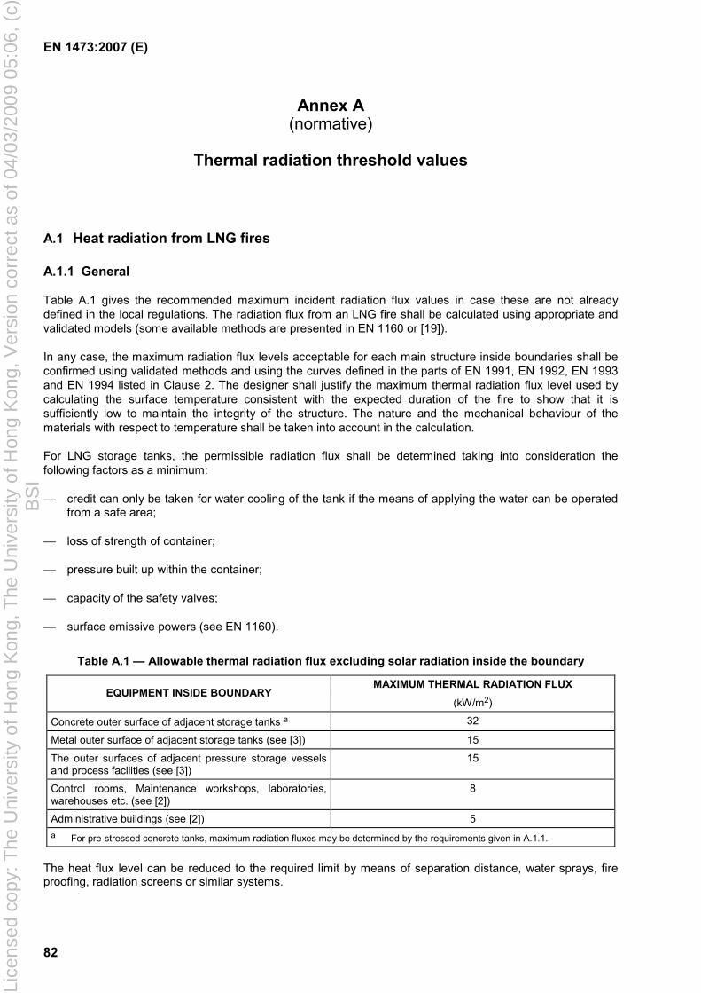
EN 1473:2007 (E)
82
Annex A (normative)
Thermal radiation threshold values
A.1 Heat radiation from LNG fires
A.1.1 General
Table A.1 gives the recommended maximum incident radiation flux values in case these are not already defined in the local regulations. The radiation flux from an LNG fire shall be calculated using appropriate and validated models (some available methods are presented in EN 1160 or [19]).
In any case, the maximum radiation flux levels acceptable for each main structure inside boundaries shall be confirmed using validated methods and using the curves defined in the parts of EN 1991, EN 1992, EN 1993 and EN 1994 listed in Clause 2. The designer shall justify the maximum thermal radiation flux level used by calculating the surface temperature consistent with the expected duration of the fire to show that it is sufficiently low to maintain the integrity of the structure. The nature and the mechanical behaviour of the materials with respect to temperature shall be taken into account in the calculation.
For LNG storage tanks, the permissible radiation flux shall be determined taking into consideration the following factors as a minimum:
credit can only be taken for water cooling of the tank if the means of applying the water can be operated from a safe area;
loss of strength of container;
pressure built up within the container;
capacity of the safety valves;
surface emissive powers (see EN 1160).
Table A.1 — Allowable thermal radiation flux excluding solar radiation inside the boundary
MAXIMUM THERMAL RADIATION FLUX EQUIPMENT INSIDE BOUNDARY
(kW/m2)
Concrete outer surface of adjacent storage tanks a 32 Metal outer surface of adjacent storage tanks (see [3]) 15 The outer surfaces of adjacent pressure storage vessels and process facilities (see [3])
15
Control rooms, Maintenance workshops, laboratories, warehouses etc. (see [2])
8
Administrative buildings (see [2]) 5 a For pre-stressed concrete tanks, maximum radiation fluxes may be determined by the requirements given in A.1.1.
The heat flux level can be reduced to the required limit by means of separation distance, water sprays, fire proofing, radiation screens or similar systems.
Lice
nsed
cop
y: T
he U
nive
rsity
of H
ong
Kon
g, T
he U
nive
rsity
of H
ong
Kon
g, V
ersi
on c
orre
ct a
s of
04/
03/2
009
05:0
6, (
c)B
SI
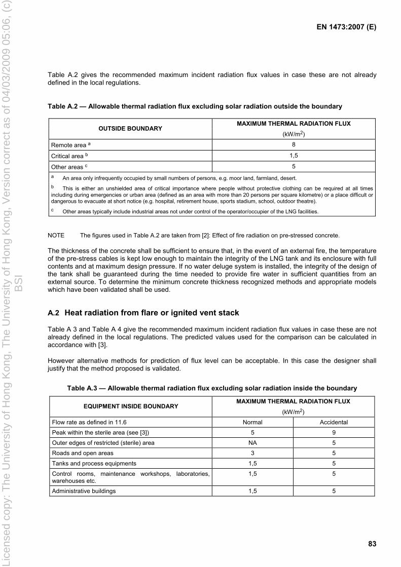
EN 1473:2007 (E)
83
Table A.2 gives the recommended maximum incident radiation flux values in case these are not already defined in the local regulations.
Table A.2 — Allowable thermal radiation flux excluding solar radiation outside the boundary
MAXIMUM THERMAL RADIATION FLUX OUTSIDE BOUNDARY
(kW/m2)
Remote area a 8 Critical area b 1,5 Other areas c 5 a An area only infrequently occupied by small numbers of persons, e.g. moor land, farmland, desert. b This is either an unshielded area of critical importance where people without protective clothing can be required at all times including during emergencies or urban area (defined as an area with more than 20 persons per square kilometre) or a place difficult or dangerous to evacuate at short notice (e.g. hospital, retirement house, sports stadium, school, outdoor theatre). c Other areas typically include industrial areas not under control of the operator/occupier of the LNG facilities.
NOTE The figures used in Table A.2 are taken from [2]: Effect of fire radiation on pre-stressed concrete.
The thickness of the concrete shall be sufficient to ensure that, in the event of an external fire, the temperature of the pre-stress cables is kept low enough to maintain the integrity of the LNG tank and its enclosure with full contents and at maximum design pressure. If no water deluge system is installed, the integrity of the design of the tank shall be guaranteed during the time needed to provide fire water in sufficient quantities from an external source. To determine the minimum concrete thickness recognized methods and appropriate models which have been validated shall be used.
A.2 Heat radiation from flare or ignited vent stack
Table A 3 and Table A 4 give the recommended maximum incident radiation flux values in case these are not already defined in the local regulations. The predicted values used for the comparison can be calculated in accordance with [3].
However alternative methods for prediction of flux level can be acceptable. In this case the designer shall justify that the method proposed is validated.
Table A.3 — Allowable thermal radiation flux excluding solar radiation inside the boundary
MAXIMUM THERMAL RADIATION FLUX EQUIPMENT INSIDE BOUNDARY
(kW/m2)
Flow rate as defined in 11.6 Normal Accidental Peak within the sterile area (see [3]) 5 9 Outer edges of restricted (sterile) area NA 5 Roads and open areas 3 5
Tanks and process equipments 1,5 5 Control rooms, maintenance workshops, laboratories, warehouses etc.
1,5 5
Administrative buildings 1,5 5
Lice
nsed
cop
y: T
he U
nive
rsity
of H
ong
Kon
g, T
he U
nive
rsity
of H
ong
Kon
g, V
ersi
on c
orre
ct a
s of
04/
03/2
009
05:0
6, (
c)B
SI
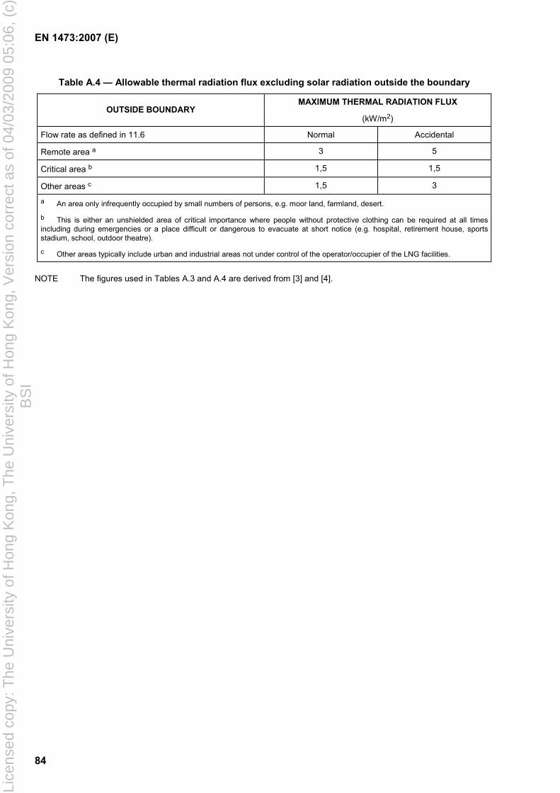
EN 1473:2007 (E)
84
Table A.4 — Allowable thermal radiation flux excluding solar radiation outside the boundary
MAXIMUM THERMAL RADIATION FLUX OUTSIDE BOUNDARY
(kW/m2)
Flow rate as defined in 11.6 Normal Accidental Remote area a 3 5
Critical area b 1,5 1,5
Other areas c 1,5 3 a An area only infrequently occupied by small numbers of persons, e.g. moor land, farmland, desert.
b This is either an unshielded area of critical importance where people without protective clothing can be required at all times including during emergencies or a place difficult or dangerous to evacuate at short notice (e.g. hospital, retirement house, sports stadium, school, outdoor theatre).
c Other areas typically include urban and industrial areas not under control of the operator/occupier of the LNG facilities.
NOTE The figures used in Tables A.3 and A.4 are derived from [3] and [4].
Lice
nsed
cop
y: T
he U
nive
rsity
of H
ong
Kon
g, T
he U
nive
rsity
of H
ong
Kon
g, V
ersi
on c
orre
ct a
s of
04/
03/2
009
05:0
6, (
c)B
SI
EN 1473:2007 (E)
85
Annex B (normative)
Definitions of reference flow rates
B.1 General
The various flow rates of gaseous discharges are defined below.
B.2 VT (heat input)
The VT maximum flow rate of a tank ("boil off") due to heat input in normal operation is to be determined by assuming ambient air at the maximum temperature observed in the course of a hot summer day.
B.3 VL (fluid input)
Filling of the tank generate a piston effect. The maximum volume flow rate for tank filling is to be taken for the value of VL the resulting gas volume flow rate (expressed under the actual conditions of temperature and pressure in the gaseous crown of the tank).
VL is the highest flow rate possible with the inlet control valve failed open.
B.4 VO (over filling)
If over filling leading to spillage of LNG into the annular tank space cannot be excluded, the instantaneous vaporisation of the LNG entering the tank shall be considered. The steps taken in 6.6.2 can be reinforced as required.
B.5 VF (flash at filling)
At LNG filling of the tank, instantaneous vaporisation occurs (called "Flash"). The main reasons of LNG flash are the following:
heating of the LNG due to the pumping;
heat input from piping during loading or unloading;
cooling of the tank wall when the liquid level increases, (due to the fact that the temperature of the vapour phase of the above part of the tank is higher than the temperature of the liquid, consequently the wall tank is cooled down when the level of LNG increases producing vaporisation);
mixing of the LNG already stored;
when the pressurised LNG sent into the tank has a temperature before expansion higher than that of the bubble point of the liquid at tank pressure, instantaneous vaporisation occurs.
Lice
nsed
cop
y: T
he U
nive
rsity
of H
ong
Kon
g, T
he U
nive
rsity
of H
ong
Kon
g, V
ersi
on c
orre
ct a
s of
04/
03/2
009
05:0
6, (
c)B
SI
EN 1473:2007 (E)
86
VF, volume of the flash at filling shall be at the maximum filling rate with the control valve failed open and shall be determined including all the above parameter.
If the LNG was initially at equilibrium, the fractional proportion of liquid which vaporises instantaneously (F) due to a temperature before expansion higher than that of bubble point of the stored LNG can be calculated rigorously or approximated by the following simplified equation:
( )
−−=
LTTC
F 12exp1
where
C is the heat capacity of the fluid (J K-1 kg-1);
T2 is the boiling-point temperature of the fluid at the pressure of the tank (K);
T1 is the temperature of the fluid before expansion (K);
L is the latent heat of vaporisation of the fluid (J kg-1).
Consequently VF is calculated using the following equation:
kg/s)(inrateflowfilling×= FVF
In the absence of more precise data, if the drop of absolute pressure is less or equal to one bar, the following values can be used:
113 kg.JK.1053,3 −−×=C ;
13 Jkg10504 −×=L ;
( ) ( ) 0008/1212 ppTT −=− ;
where
(p2 – p1) expressed in Pascals, represents the absolute pressure reduction of the LNG between the initial storage and the pressure of the destination tank.
B.6 VR (LNG recirculation by a submersible pump)
VR represents the mass flow rate of boil-off brought about by internal recirculation of the LNG by the largest of the submersible pumps.
VR can be estimated using the simplified following formula taken into consideration the assumption that all the energy of the pump goes into the fluid:
VR = Energy input per pump / L.
The energy is expressed in J/h and L in J/kg (see B.5).
Lice
nsed
cop
y: T
he U
nive
rsity
of H
ong
Kon
g, T
he U
nive
rsity
of H
ong
Kon
g, V
ersi
on c
orre
ct a
s of
04/
03/2
009
05:0
6, (
c)B
SI
EN 1473:2007 (E)
87
B.7 VA (variation in atmospheric pressure)
If the pressure in the tank is equal to maximum operating pressure, a drop in atmospheric pressure brings about a gaseous discharge from expansion of vapour in the crown (VAG) plus vapour evolved from the overheat of the liquid (VAL). Similarly a vacuum condition can arise following an increase in atmospheric pressure.
VAG the flow rate due to vapour expansion can be calculated using the following formula (VAG expressed in m3/hour under actual conditions of pressure and of temperature of the gaseous crown sheet):
tp
pVVAG d
d×=
where
V is the maximum gaseous cubic capacity of empty tank (m3);
p is the absolute operating pressure (Pa);
dp/dt is the absolute value of rate of variation in atmospheric pressure (Pa/h);
VAL the flow rate due to the de-superheating of liquid can be estimated by adapting the methods given above in B.5 for the calculation of F.
VA = VAG + VAL
Local data for rate of atmospheric pressure change shall be used. Where there is no local data available a drop in atmospheric pressure of 2 000 Pa/h with total variation of 10 kPa can be assumed.
This value also enables the calculation of the incoming volume of flow in the event of an increase in atmospheric pressure.
B.8 VV (control valve failure)
Failure of a control valve can lead to increased vapour loads as for example from a suddenly increased filling rate or untimely opening of a vacuum breaker valve.
B.9 VI (heat input in the course of a fire)
The rate of evaporation in the course of a fire is determined by assuming that incoming heat is used immediately for vaporising the fluid taking no credit for the effect of firewater.
The heat flow received by the vertical external enclosure of the tank is assumed, by default, to be equal to the emissive power of a flame of LNG (see EN 1160).
This value is overruled by the worst case value of heat radiation in the hazard assessment for the actual location of the tank.
Lice
nsed
cop
y: T
he U
nive
rsity
of H
ong
Kon
g, T
he U
nive
rsity
of H
ong
Kon
g, V
ersi
on c
orre
ct a
s of
04/
03/2
009
05:0
6, (
c)B
SI
EN 1473:2007 (E)
88
B.10 VD (fluid suction)
Withdrawal of liquid shall be offset by a gaseous input in order to prevent negative pressure. The volume flow rate of gas is taken to be equal to the maximum volume flow rate of the suction pumps.
B.11 VC (compressors suction)
Natural evaporation which occurs in the tank is generally removed by boil off gas compressors. Even though the suction volume flow rate of such compressors is adjusted in normal working conditions to fit the rate of evaporation, the possibility that the compressors will cause negative pressure in the tank cannot be excluded. VC represents the maximum suction volume flow rate of the compressors.
B.12 VB (roll-over)
The boil off due to a roll-over shall be calculated using appropriate validated models.
In case where no model is used, the flow rate during roll-over shall be conservatively taken equal to:
TB VV ×= 100
This flow rate corresponds approximately to the maximum flow rate observed in the past during a real roll-over.
Lice
nsed
cop
y: T
he U
nive
rsity
of H
ong
Kon
g, T
he U
nive
rsity
of H
ong
Kon
g, V
ersi
on c
orre
ct a
s of
04/
03/2
009
05:0
6, (
c)B
SI
EN 1473:2007 (E)
89
Annex C (informative)
Seismic classification
C.1 Introduction
This annex provides a methodology for the seismic classification of plant and equipment to allow the design of the plant to provide the correct level of earthquake resistance to an earthquake event as defined in 4.5.2.2.
C.2 Some basic principles
• The seismic classes are defined in 4.5.2.2.
• The plant should be shutdown after any earthquake the magnitude of which exceeds a value less than the OBE acceleration value (this value to be specified by the owner/operator).
This shutdown decision can be operator initiated, or automatically from seismic detectors to facilitate an orderly shutdown rather than a random trip of machinery caused by individual vibration detection devices.
• A full safety inspection shall be carried out prior to resuming operation to check:
operability;
Integrity;
stability.
• After OBE all equipment and/or systems shall remain operational, except, if agreed by owner/operator, that equipment and/or systems that are not necessary for plant operation.
• After SSE the plant is in a safe condition. In the period following the event additional measures may need to be taken to ensure safe reinstatement or, if necessary, decommissioning of the plant. These operations could take weeks or months.
• The Safety Management System shall describe the emergency procedures to be activated after SSE, allowing for availability of staff, for plant monitoring, inspection and to undertake temporary measures.
C.3 Example of safety approach after SSE
Local small leaks are accepted but the plant should keep its integrity to avoid additional hazard from hydrocarbon spillage.
The Central Control Room (CCR) becomes the operational crisis centre.
It is accepted that the CCR would not receive full plant operational information but major information i.e. pressure, level and temperature on large hydrocarbon inventories, such as storage tanks and refrigerant containers, should be reported in the CCR.
Lice
nsed
cop
y: T
he U
nive
rsity
of H
ong
Kon
g, T
he U
nive
rsity
of H
ong
Kon
g, V
ersi
on c
orre
ct a
s of
04/
03/2
009
05:0
6, (
c)B
SI
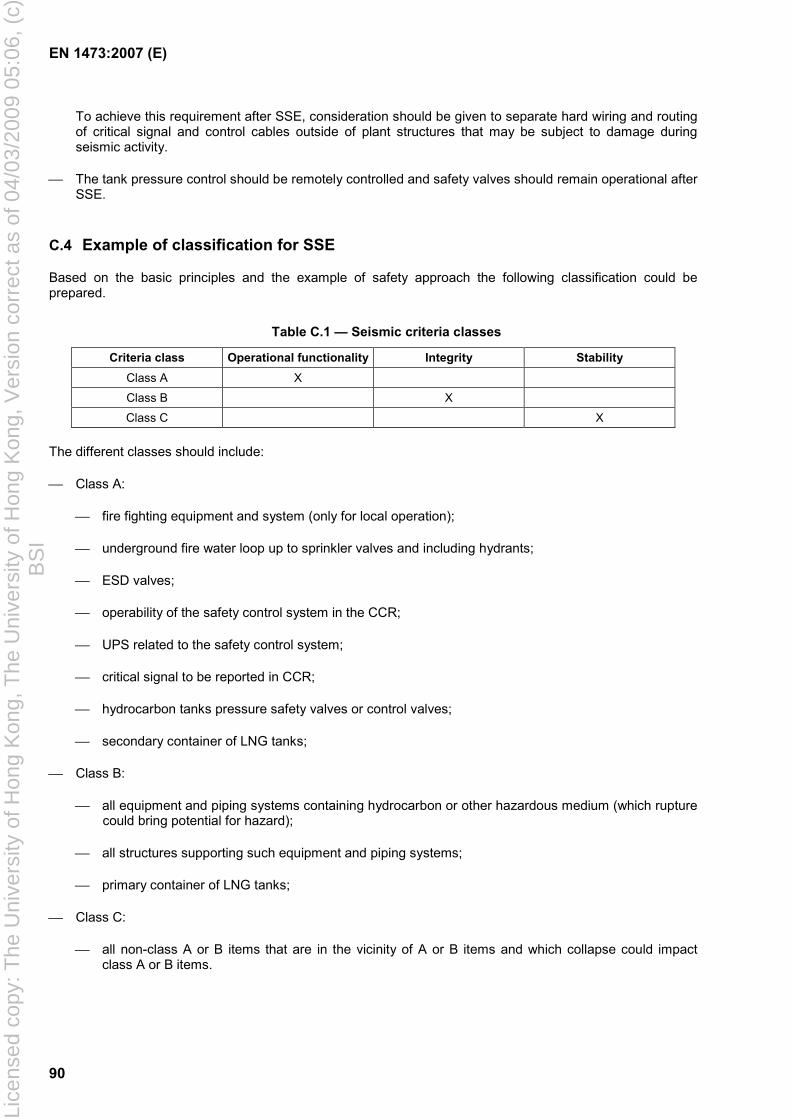
EN 1473:2007 (E)
90
To achieve this requirement after SSE, consideration should be given to separate hard wiring and routing of critical signal and control cables outside of plant structures that may be subject to damage during seismic activity.
The tank pressure control should be remotely controlled and safety valves should remain operational after SSE.
C.4 Example of classification for SSE
Based on the basic principles and the example of safety approach the following classification could be prepared.
Table C.1 — Seismic criteria classes
Criteria class Operational functionality Integrity Stability Class A X
Class B X
Class C X
The different classes should include:
Class A:
fire fighting equipment and system (only for local operation);
underground fire water loop up to sprinkler valves and including hydrants;
ESD valves;
operability of the safety control system in the CCR;
UPS related to the safety control system;
critical signal to be reported in CCR;
hydrocarbon tanks pressure safety valves or control valves;
secondary container of LNG tanks;
Class B:
all equipment and piping systems containing hydrocarbon or other hazardous medium (which rupture could bring potential for hazard);
all structures supporting such equipment and piping systems;
primary container of LNG tanks;
Class C:
all non-class A or B items that are in the vicinity of A or B items and which collapse could impact class A or B items.
Lice
nsed
cop
y: T
he U
nive
rsity
of H
ong
Kon
g, T
he U
nive
rsity
of H
ong
Kon
g, V
ersi
on c
orre
ct a
s of
04/
03/2
009
05:0
6, (
c)B
SI
EN 1473:2007 (E)
91
Annex D (normative)
Specific requirements for LNG pumps
D.1 Introduction
This annex defines additional requirements to the ones described in Clause 7.
D.2 Design
The design shall meet the following specifications:
thermal transient operating conditions shall be taken into account (see EN 1160);
flanges, gaskets and fasteners (nuts and bolts) for the joint shall be in accordance with recommendations given in 9.5;
flanged joints shall be tested in accordance with EN 12308.
The manufacture and assembly shall meet the following requirements:
provisions shall be made that fasteners remain tight due to the effect of temperature change or vibration;
traces of oxidation and other contaminants shall be removed prior to fabrication or assembly;
welding processes and procedures, quality of the electrodes, wires and flux shall be in accordance with EN ISO 15607, EN ISO 15609-1 and EN 15614-1.
The unit shall be fitted with a system for compensating the residual axial thrust of the pump under all operating and transient conditions.
D.3 Inspection
D.3.1 General
To ensure the safety behaviour, pump components subjected to mechanical, rotational and thermal stresses shall be inspected and tested. Inspection and tests shall be performed in accordance with the relevant standards.
The pump manufacturer shall set up, in compliance with the owner requirements, a quality plan with a full inspection programme which shall include the inspection defined in D.3.2 to D.3.8 where applicable. The requirements for positive material identification shall be stated in the quality plan.
The manufacturer shall demonstrate the reliability of the applied procedure in accordance with the referred standard and the adequacy of the selected criteria with regard to the required quality level.
D.3.2 Inspection of components submitted to pressure or rotation
The chemical analyses and the mechanical characteristics shall be supplied for each casting.
Lice
nsed
cop
y: T
he U
nive
rsity
of H
ong
Kon
g, T
he U
nive
rsity
of H
ong
Kon
g, V
ersi
on c
orre
ct a
s of
04/
03/2
009
05:0
6, (
c)B
SI
EN 1473:2007 (E)
92
For forged or rolled parts, mechanical tests shall be performed after any heat treatment. For each component, the supplier shall specify the reference standards, the sampling location and its direction.
D.3.3 Radiographic inspection
Radiographic inspection shall be conducted in accordance with EN 473 and EN 1435.
D.3.4 Ultrasonic inspection
Ultrasonic inspection shall be conducted in compliance with EN 473 and EN 1714.
D.3.5 Crack detection (dye penetrant inspection)
Dye penetrant inspection shall be conducted in accordance with EN 473, EN 571-1 and EN 970.
D.3.6 Visual inspection
Visual inspection shall be carried out in order to check the compliance of the products supplied with the specifications of 7.2 and the individual component marking in accordance with the quality plan.
D.3.7 Dimensional inspection
The dimensional inspection shall be carried out in order to check whether the products supplied comply with the standards applicable to the supplier's plans and to the documents he shall give to the owner.
D.3.8 Electrical inspections
The following inspections shall be carried out:
electrical tests in accordance with the quality plan;
an electrical balancing test.
Electrical components shall be certified in accordance with the appropriate hazardous area classification.
D.4 Testing
D.4.1 Test condition
All the following tests, which are given hereafter, shall be conducted either with liquid nitrogen or with LNG unless otherwise stated.
Acceptable alternative test liquids can be used with the owner's agreement.
For all test liquids other than LNG, detail procedures and formulae shall be agreed between the manufacturer and the owner to predict the actual performance from the test data.
D.4.2 Type tests and acceptance tests
Type tests are carried out on the first of each pump type. Acceptance tests are carried out on all pumps of this design. Type tests shall include the following:
mechanical strength and tightness tests (hydrostatic tests);
Lice
nsed
cop
y: T
he U
nive
rsity
of H
ong
Kon
g, T
he U
nive
rsity
of H
ong
Kon
g, V
ersi
on c
orre
ct a
s of
04/
03/2
009
05:0
6, (
c)B
SI
EN 1473:2007 (E)
93
performance tests;
net positive suction head (NPSH) tests (the definition of NPSH is given in EN ISO 9906);
cold rotation tests at a maximum temperature of − 160 °C (for pumps not tested with LNG).
Acceptance tests shall include at least the strength and tightness tests.
By special agreement with the pump supplier, the acceptance tests can also be extended to performance and NPSH tests. Acceptance tests shall be carried out either at the manufacturer’s premises if the latter disposes of a test bench, or at a location decided by mutual agreement between the manufacturer and the owner/operator.
D.4.3 Strength and tightness tests
The pump body and any part of the pump under pressure (i.e. working barrel), shall undergo a strength test and a tightness test in accordance with EN 12162. Water can be used for these tests provided that chloride content is lower than 50 × 10-6 (50 ppm).
D.4.4 Performance tests
Performance tests shall be carried out preferably with LNG, the composition of which shall be specified and density and temperature shall be measured.
Test data shall be recorded or calculated, at least for six points of the operating range among which:
shutoff flow rate;
minimum continuous stable flow rate;
two points in midway between minimum and rated flow rate;
rated flow rate;
maximum allowable flow rate.
The tests shall be conducted at the pump's nominal speed ± 3 % when LNG or at appropriate speed in the case of another medium, to be agreed with the owner.
For each of the flow rates except shutoff, the following parameters are determined:
total hydraulic head at discharge;
total hydraulic head at suction;
pump efficiency and efficiency of the motor;
power absorbed by the motor;
vibration level;
noise level.
For shutoff point, the following parameters are determined:
total hydraulic head at discharge;
Lice
nsed
cop
y: T
he U
nive
rsity
of H
ong
Kon
g, T
he U
nive
rsity
of H
ong
Kon
g, V
ersi
on c
orre
ct a
s of
04/
03/2
009
05:0
6, (
c)B
SI
EN 1473:2007 (E)
94
power absorbed by the motor, if appropriate.
For pumps fitted with variable speed drivers, these parameters are also recorded at two different speeds of operation band (medium and minimum speed).
For a vertical motor pump submerged in the tank, a “pump down” test shall be carried out, the conditions of which shall be submitted for the owner's approval. Pump down test is a test of the pump at low liquid level equivalent to a reduction of discharge head to 40 % of the nominal value.
A continuous running test of minimum 1 h shall be conducted at rated duties.
D.4.5 NPSH tests
Measurements of the NPSH required by the pump shall be carried out at the equilibrium temperature of the liquid, preferably with LNG, the composition of which shall be specified, and at least 3 different flow rates for the first pump whilst only one for the other with same design. These flow rates shall be identical with those of the performance tests.
D.5 Declared values
For a liquefied natural gas, the density of which shall be specified at the reference temperature, the manufacturer shall declare the following values:
differential head at shutoff;
differential head at the minimum flow rate of the operating range;
differential head at the nominal flow rate;
differential head at the maximum flow rate of the operating range;
NPSH required at the minimum flow rate of the operating range;
NPSH required at the nominal flow rate;
NPSH required at the maximum flow rate of the operating range;
power consumption at the nominal flow rate;
pump efficiency at the nominal flow rate and of its drive and speed converter, if any;
pump down level in the case of an in tank pump (see D.4.4).
power consumption at the minimum continuous and maximum flow rates.
The tolerances on these values determined during the course of the performance tests (see D.4.4) shall be as specified in EN ISO 13709.
D.6 Marking
A metal identification plate showing the following information should be fixed to each pump and working barrel:
supplier's distinguishing abbreviation;
Lice
nsed
cop
y: T
he U
nive
rsity
of H
ong
Kon
g, T
he U
nive
rsity
of H
ong
Kon
g, V
ersi
on c
orre
ct a
s of
04/
03/2
009
05:0
6, (
c)B
SI
EN 1473:2007 (E)
95
manufacturing serial number and owner's order number;
nominal flow rate (in m3/h);
nominal head of the pump (in meters);
rotation speed at the nominal flow rate (in min-1);
maximum working pressure (in bar gauge) and the date of testing of the working barrel, if any;
date and pressure of pump test (see EN 12162).
D.7 Particular requirements for submerged pumps and related cables
D.7.1 Pot (can) mounted pumps
An electrical junction box shall be used for the connection between the electric cables of the pump and the external cables.
Due provision shall be made to avoid any gas migration from the suction pot into the junction box.
The cryogenic electric cables for the connections between the junction box and the pump motor shall withstand a working temperature of − 196 °C.
D.7.2 Column mounted (in tank) type
D.7.2.1 General
With a proper procedure, column mounted type pumps can be removed from the storage tank whilst it is in service. The pump and electrical cable assembly is inserted into the upper end of the pump column. The pump is sealed onto an adapter at the base of the column.
Suction is through the base adapter and discharge on the periphery of the pump body, between the column and the pump body.
In addition to the requirements of Clause 7 and D.2, the pump unit shall be able to be installed and removed by means of a lifting system using either dedicated cables or a set of connecting stainless steel tubes or some other means.
The column head plate seals the column. It shall comprise:
on the inside: a tensioning system for the cable which secures the electric cables and the lifting cable coiled under the plate;
on the outside: the electric cable junction box.
The base adapter shall ensure pump alignment in the centre of the column and prevent it from rotating. It shall allow the pump to be raised without requiring the application of any abnormal force.
D.7.2.2 Dedicated cables
The devices for handling the unit and for securing the cables shall include:
a lifting system for the safe lowering and raising of the pump, without risk of falling and without twisting of cables;
Lice
nsed
cop
y: T
he U
nive
rsity
of H
ong
Kon
g, T
he U
nive
rsity
of H
ong
Kon
g, V
ersi
on c
orre
ct a
s of
04/
03/2
009
05:0
6, (
c)B
SI
EN 1473:2007 (E)
96
a spare lifting cable that will take over the function of the duty cable, in case of its failure; this spare cable shall be installed in such a way that it will prevent pump falling in case of duty cable failure. This spare lifting cable could only be discarded if owner/operator can demonstrate otherwise;
an electrical support cable used for keeping the electrical cables under tension in the column, this cable shall be non-twisting type and shall be pre-stressed before assembly to avoid possible over stressing of the electrical cables due to temperature difference in the tank;
a system for guiding the cables into the column;
a system for supporting a measurement cable stemming.
The electric cables shall have a bending radius which allows easy handling while avoiding breakage under the cable's own weight.
D.7.2.3 Stainless steel tubes
Where stainless steel tubes are used a shut-off device (a gate valve, or spectacle type blind flange, or any other suitable closing device) may be placed on top of the column outside the tank.
The pump shall be lifted by a set of connecting stainless steel tubes which also contain the electric power supply cables. This lifting mechanism shall be rigid, easy to assemble and shall protect the electric cables.
D.8 Vertical external motor pumps
The unit comprises an electric motor/centrifugal pump assembly.
The vertical pump is installed in a barrel with the pump submerged in the LNG. The electrical motor is mounted on top of the barrel and is not submerged in the LNG.
Careful consideration shall be given to sealing arrangements. Shaft sealing shall eliminate leakage past the seal.
The cooling down of the pumps shall be carried out slowly and carefully. Each pump shall be provided with an adequate vent or relief valve to prevent over-pressure during cool-down.
The barrel shall be insulated in order to prevent vaporisation and to inhibit condensation. The foundations of the pump shall be designed and constructed to prevent frost heaving.
Lice
nsed
cop
y: T
he U
nive
rsity
of H
ong
Kon
g, T
he U
nive
rsity
of H
ong
Kon
g, V
ersi
on c
orre
ct a
s of
04/
03/2
009
05:0
6, (
c)B
SI
EN 1473:2007 (E)
97
Annex E (normative)
Specific requirements for LNG vaporisers
E.1 Operating parameters/declared performance
The operating parameters of vaporisers for which the nominal values are to be specified according to type are given in Table E.1. The range within which these parameters will be able to vary shall also be specified.
Certain of these values shall be declared by the manufacturer. More specific requirements are given below.
E.2 Water stream vaporisers: Open rack type
E.2.1 Specific design requirements
Open rack vaporisers shall be protected against adverse atmospheric conditions such as wind, snow and rain. In particular wind shield should be provided to limit sea water foam dispersion by the wind.
The two following variable actions shall be considered in the determination of the normal action used for design:
exceptional thermal stress resulting from poor distribution of water e.g. a heating tube is not wetted;
accumulation of ice (10 cm thick) on half the height of the vaporiser.
E.2.2 Water distribution
Flow of water shall be even:
on the different accessible parts of any section of tube in order to prevent distortions of the tube;
between different tubes which are mechanically connected.
The system for distribution of water over the tubes should be easily accessible, adjustable and designed to permit cleaning, if required by the owner without interrupting operation, using one of the following methods:
jet of water;
blast of air under pressure;
rodding brush.
Lice
nsed
cop
y: T
he U
nive
rsity
of H
ong
Kon
g, T
he U
nive
rsity
of H
ong
Kon
g, V
ersi
on c
orre
ct a
s of
04/
03/2
009
05:0
6, (
c)B
SI
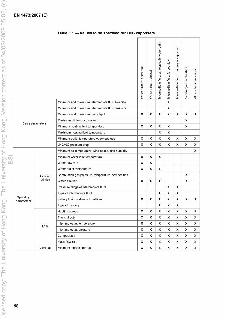
EN 1473:2007 (E)
98
Table E.1 — Values to be specified for LNG vaporisers
Wat
er s
tream
: ope
n ra
ck
Wat
er s
tream
: clo
sed
Inte
rmed
iate
flui
d: a
tmos
pher
ic w
ater
bat
h
Inte
rmed
iate
flui
d: fo
rced
flow
Inte
rmed
iate
flui
d: c
onde
nser
vap
oris
er
Sub
mer
ged
com
bust
ion
Atm
osph
eric
vap
oris
er
Minimum and maximum intermediate fluid flow rate X
Minimum and maximum intermediate fluid pressure X
Minimum and maximum throughput X X X X X X X
Maximum utility consumption X
Minimum heating fluid temperature X X X X X
Maximum heating fluid temperature X X
Minimum outlet temperature vaporised gas X X X X X X X
Basis parameters
LNG/NG pressure drop X X X X X X X
Minimum air temperature, wind speed, and humidity X
Minimum water inlet temperature X X X
Water flow rate X X
Water outlet temperature X X X
Combustion gas pressure, temperature, composition X
Water analysis X X X X
Pressure range of intermediate fluid X X
Type of intermediate fluid X X X
Battery limit conditions for utilities X X X X X X X
Service utilities
Type of heating X X X
Heating curves X X X X X X X
Thermal duty X X X X X X X
Inlet and outlet temperature X X X X X X X
Inlet and outlet pressure X X X X X X X
Composition X X X X X X X
LNG
Mass flow rate X X X X X X X
Operating parameters
General Minimum time to start up X X X X X X X
Lice
nsed
cop
y: T
he U
nive
rsity
of H
ong
Kon
g, T
he U
nive
rsity
of H
ong
Kon
g, V
ersi
on c
orre
ct a
s of
04/
03/2
009
05:0
6, (
c)B
SI
EN 1473:2007 (E)
99
E.2.3 LNG and NG lines
Stress analysis shall be performed on both LNG inlet lines and NG outlet lines to allow proper flexibility and minimize loads on panel connections.
E.2.4 LNG distribution
Care shall be taken with the distribution of the LNG flow between parallel vaporisation channels. One solution consists of having a generously dimensioned manifold and a restriction at the inlet of each exchanger tube.
E.2.5 Cleaning of the LNG/NG circuit
Gas circulating in the exchanger can contain paraffin waxes. These deposit on the sidewalls of tubes and reduce the performance of vaporisers. In that case a facility for flushing tubes with the aid of a suitable solvent shall be provided. The solvent used shall be compatible with the materials used.
E.2.6 Control/safety
Safe operation is achieved by the control of the vaporiser gas outlet temperature and water flow rate, which form the basis of the alarm and safety system.
In case of low gas outlet temperature or low water flow the vaporiser shall be automatically isolated. Gas outlet valve closure time should be set to prevent cold temperature extending over limits defined by thermal transient analysis (see 8.1.2).
Threshold values for gas outlet temperature shall be defined. Typical values might be:
0 °C for alarm;
− 5 °C for operation of safety shutdown devices to stop LNG feed.
Where the minimum ambient temperature is below the trip threshold, start up of the vaporiser can require a carefully designed override.
Insufficient flow of water shall be automatically detected (e.g. flow sensor).
E.2.7 Shelters for vaporisers
If revamping of the coating of finned tubes requires dismantling of components, the building shall be designed accordingly i.e. with a removable roof.
Any side panels shall be designed to prevent any projection of water to the outside (water shall be returned to the lower reception basin).
Inspection traps systems shall be provided to permit inspection in operation.
E.2.8 Water circuits
Water circuits (pumps, pipe-work, water heating, chlorination) are to meet the requirements listed in 12.5.
E.2.9 Water quality
The water quality shall be checked for compatibility with tube material.
Lice
nsed
cop
y: T
he U
nive
rsity
of H
ong
Kon
g, T
he U
nive
rsity
of H
ong
Kon
g, V
ersi
on c
orre
ct a
s of
04/
03/2
009
05:0
6, (
c)B
SI
EN 1473:2007 (E)
100
When water contains fines and solid particles the vendor should recommend the most appropriate protection such as water filtration.
E.3 Water stream vaporisers : Closed type
The flow rate and the temperature of the water shall be controlled.
Vaporisers shall be operated with tube surface temperatures above 0 °C, so that formation of ice will be avoided. During upset conditions, when water throughput is insufficient, the supply of LNG shall be reduced or stopped. If necessary, water shall be drained from the shell side of the heat exchanger.
Threshold values for gas outlet temperatures shall be defined. Typical values might be:
+ 15 °C, for alarm;
+ 10 °C, for operation of safety shutdown devices to stop LNG feed.
The water flow rate shall be temperature controlled. In order to avoid blockage, an additional water flow rate detector shall be installed to stop throughput of LNG in case of insufficient water flow.
E.4 Intermediate fluid vaporisers
E.4.1 Atmospheric water bath type
Control shall be based on the temperature of the water bath. If an external pump is used for forced circulation of the water, the non-availability of this pump shall be considered and should cause a unit shutdown.
Threshold values for gas outlet temperatures shall be defined. Typical value might be:
+ 15 °C, for alarm;
+ 10 °C, for shutdown.
The water bath temperature shall be controlled by the heat supply. In the event of heat supply shut down, the LNG feed shall be stopped.
E.4.2 Forced flow type
The principles of control are similar to those of the closed water stream vaporiser with the difference that the set point of the alarms and shut down are dependent on the physical properties of the intermediate fluid.
The outlet temperature of the vaporised LNG controls the flow rate of the intermediate fluid in the circuit. In case of upset conditions of the intermediate fluid circuit the LNG throughput shall be stopped.
E.4.3 Condenser/vaporiser type
Condenser vaporiser systems are temperature controlled. LNG is vaporised against intermediate fluids. Alarm and shutdown functions shall be dependent on physical properties of the intermediate flow and equipment design conditions.
The temperature controller of the vaporised LNG at the outlet of the vaporiser shall act on the heating source of the system.
Lice
nsed
cop
y: T
he U
nive
rsity
of H
ong
Kon
g, T
he U
nive
rsity
of H
ong
Kon
g, V
ersi
on c
orre
ct a
s of
04/
03/2
009
05:0
6, (
c)B
SI
EN 1473:2007 (E)
101
E.5 Submerged combustion type vaporisers
E.5.1 Corrosion
The selection of material and design of the vaporiser should avoid corrosion.
Water pH should be regularly monitored to avoid tube pitting corrosion.
Care shall be taken with the anti-corrosion treatment of components made of carbon steel (stacks, supports etc.) due to the potential acidic environment.
E.5.2 Control and safety
The use of a programmable controller is preferred.
The primary parameter governing the operation of the burner is the gas outlet temperature, however the water bath temperature should be low enough for good energy efficiency but sufficiently high to prevent freezing.
The parameters governed by the automatic burner control system are the flow rates of fuel gas and air.
A submerged combustion vaporiser should include a pilot flame. The control system shall distinguish three steady state operating modes for the pilot:
shutdown;
standby (only the pilot flame is on);
normal operation.
Flame sensors monitor permanently the presence of a flame during "standby" and "normal operation".
Safety devices which could initiate shutdown of the equipment are to be the following, as a minimum:
too low bath water temperature;
too low gas outlet temperature;
too low bath level;
extinction of flame;
gas detection in the incoming air;
air fan tripping.
Threshold values for gas outlet temperature, shall be defined. Typical values might be:
0 °C for alarm;
− 5 °C for shutdown of a vaporiser or of a set of vaporisers, according to the position of the temperature probe within the gas circuit.
Where the trip threshold is above the minimum ambient temperature, start up of the vaporiser can require a carefully designed override.
Lice
nsed
cop
y: T
he U
nive
rsity
of H
ong
Kon
g, T
he U
nive
rsity
of H
ong
Kon
g, V
ersi
on c
orre
ct a
s of
04/
03/2
009
05:0
6, (
c)B
SI
EN 1473:2007 (E)
102
In the event of trip, the control systems shall automatically:
isolate the LNG supply to that vaporiser and protect downstream pipe-works from low temperature;
cut off the gas supply to the pilot and main burners;
maintain the operation of the fan and the water circulating pump (account shall be taken in the design of the fact that water can enter the fume distribution casing and the enclosure of the burner when the fan stops, causing major thermal shock and possible damage to those parts of the equipment);
deliver an alarm signal to the appropriate control room.
E.5.3 Water bath
The construction material of the water bath shall be able to withstand the acidity of the water which results from the dissolving of fumes (carbon dioxide, nitrogen oxides) in the water. The water bath shall be leak tight.
The position of the overflow should take into account the large increase in the water level which occurs between shutdown and operation of the equipment.
E.5.4 Vibration
Fumes going through the bath generate vibration and account shall be taken of this in the design.
E.5.5 Arrangements for cold periods
Winterisation shall be considered in the design of the vaporiser.
E.5.6 Legionella
The operation of the water bath shall consider that the conditions for legionella and bacteria to develop may exist. The operator shall have a program in place to test for legionella and a plan to avoid a growth of the bacteria.
Lice
nsed
cop
y: T
he U
nive
rsity
of H
ong
Kon
g, T
he U
nive
rsity
of H
ong
Kon
g, V
ersi
on c
orre
ct a
s of
04/
03/2
009
05:0
6, (
c)B
SI
EN 1473:2007 (E)
103
Annex F (normative)
Criteria for the design of pipes
The following actions shall be considered for the calculation of supports and flexibility:
permanent criteria:
internal pressure;
weight of tube;
weight of lagging etc.;
variable criteria:
intermittent loads due to hydraulic shock;
thermal loads, due to the contraction and fatigue phenomena following cycles of cooling and heating; particular attention is required in the case of a sudden change of thickness or diameter;
snow;
wind;
earthquake, etc.
The criteria linked with hydraulic hammer are the result of maximum over-pressure created by undue stopping of a pump or the closing of a valve. These actions shall be determined using a method which has been validated by experimentation with LNG. As a first approximation the following simplified formulas may be used to calculate the values of over-pressure due to the valve closing expressed as a LNG column height, i.e. Dh:
gVv
DvLt o
h =≤ ,2
tgVL
DvLt o
h2
,2 =>
where
L is the length of pipeline;
t is the closing time of the valve;
v is the shock wave speed, v = 1 500 ms-1 for LNG;
Dh is the height of the LNG column equivalent to the over-pressure;
Vo is the flowing velocity of LNG before hydraulic hammer;
g is the acceleration due to gravity.
Lice
nsed
cop
y: T
he U
nive
rsity
of H
ong
Kon
g, T
he U
nive
rsity
of H
ong
Kon
g, V
ersi
on c
orre
ct a
s of
04/
03/2
009
05:0
6, (
c)B
SI
EN 1473:2007 (E)
104
Annex G (informative)
Description of the different types of onshore LNG installations
G.1 LNG export terminal
LNG export terminals are, by nature, located on the coast and are designed to liquefy the natural gas which will then be loaded onto LNG carriers. An LNG export terminal generally includes:
an incoming natural gas metering and receiving station, including in the case of a two phase incoming pipeline, a slug catcher;
condensate stabilisation and storage;
gas treatment units in which any acid gases, water, heavier hydrocarbons and, if appropriate, mercury which might be present in the incoming gas are extracted;
liquefaction units which produce LNG and within which, ethane, propane, commercial butane, heavier hydrocarbons and nitrogen can be extracted. A proportion of the extracted hydrocarbons can be used as refrigerant make up. A liquefaction unit uses very specific equipment such as cryogenic spool-wound or brazed plate-fin exchangers and high-powered turbo-compression units. Two refrigerant cycles in cascade are usually employed;
LNG storage tanks and the relevant loading plants for filling LNG carriers;
Liquefied Petroleum Gas (LPG) and/or natural gasoline storage tanks, if appropriate, and the relevant loading plants;
generation and/or purchase and distribution of the utilities necessary for the plant to operate (electricity, steam, cooling water, compressed air, nitrogen, fuel gas etc.);
and general off-site installations, (gas and liquid flare systems, effluent treatment, fire fighting systems etc.).
Most of the gas treating steps can be commonly found in gas treatment plant for the production of sales gas. e.g. acid gas removal, dehydration, hydrocarbon dew point and natural gas liquid (NGL) recovery. NGL fractionation is also commonly found in the light ends unit of oil refineries.
It can be noted, apart from the storage tanks, only a fraction of the hydrocarbons contained within the liquefaction plant are likely to be in the form of LNG. The bulk of the equipment volume is likely to contain high pressure natural gas, NGLs or refrigerants.
G.2 LNG receiving terminals
LNG receiving terminals are designed to receive liquefied natural gas from methane carriers, to unload, store this LNG and convert it into the gaseous phase for send out to the gas network or gas consumers.
Thus an LNG receiving terminal provides several essential functions which are:
unloading;
Lice
nsed
cop
y: T
he U
nive
rsity
of H
ong
Kon
g, T
he U
nive
rsity
of H
ong
Kon
g, V
ersi
on c
orre
ct a
s of
04/
03/2
009
05:0
6, (
c)B
SI
EN 1473:2007 (E)
105
storage;
LNG recovery and pressurising;
vaporising;
gas quality adjustment.
G.3 LNG peak shaving plants
LNG peak shaving plants, which liquefy natural gas taken from the commercial gas network, are an order of magnitude smaller than export terminals. The quality of the gas feed simplifies the processing requirements compared with an LNG export terminal. Liquid hydrocarbons are likely to be limited to the LNG and refrigerant for which storage is commonly provided. No fractionation facilities are usually required. H2S may be assumed to be present in commercial natural gas at levels below that requiring specific treatment.
The following refrigeration processes are commonly used in LNG peak shaving plants (for more details see Annex M):
one mixed refrigerant cycle;
cascade mixed refrigerant cycle;
nitrogen expander cycle;
methane/nitrogen expander cycle;
open cycle expander.
The turbo-expanders are mostly coupled to booster gas compressors.
Where a large flow of high pressure natural gas is expanded to feed a lower pressure network, the expansion can take place in a turbo-expander to provide the refrigeration needed to liquefy the natural gas. The amount of refrigeration available is directly dependent on the pressure ratio of the expansion but a common production rate is 10 % of the flow of expanded gas.
G.4 LNG satellite plants
An LNG satellite plant is generally a small station where LNG is stored and vaporised for peak shaving purposes or to supply an isolated local distribution network. The LNG is delivered by road or rail tankers or small LNG carriers coming from either an LNG receiving terminal or an LNG peak shaving plant.
The main functions of a LNG satellite plant are the same as the LNG receiving terminal.
Lice
nsed
cop
y: T
he U
nive
rsity
of H
ong
Kon
g, T
he U
nive
rsity
of H
ong
Kon
g, V
ersi
on c
orre
ct a
s of
04/
03/2
009
05:0
6, (
c)B
SI
EN 1473:2007 (E)
106
Annex H (informative)
Definition of different types of LNG tanks
H.1 General
The different types of vertical, cylindrical, flat-bottomed steel tanks are described in EN 14620-1.
Other following types could also be considered.
H.2 Spherical storage tank
The spherical, single containment tank system consists of an un-stiffened, sphere supported at the equator by a vertical cylinder. The tank is designed and constructed in compliance with the Gas Carrier Code of the International Maritime Organisation (IMO type B tank, [18]).
The spherical tank geometry allows accurate prediction of structural integrity. It can be designed for high earthquake accelerations.
An above-ground spherical tank shall be surrounded by a bund wall (see 6.8.) to contain any leakage.
H.3 Cryogenic concrete tank
A cryogenic concrete tank is either a double containment tank (see Figure H.3.) or a full containment tank (see Figure H.4.). For this type of tanks, the walls of the primary and secondary containers are both of pre-stressed concrete.
NOTE Examples of cryogenic concrete tanks are given in Figure H.6.
Lice
nsed
cop
y: T
he U
nive
rsity
of H
ong
Kon
g, T
he U
nive
rsity
of H
ong
Kon
g, V
ersi
on c
orre
ct a
s of
04/
03/2
009
05:0
6, (
c)B
SI
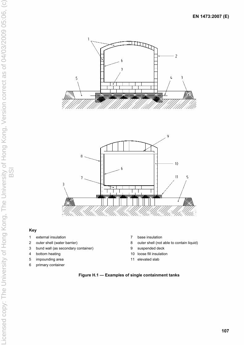
EN 1473:2007 (E)
107
Key 1 external insulation 7 base insulation 2 outer shell (water barrier) 8 outer shell (not able to contain liquid) 3 bund wall (as secondary container) 9 suspended deck 4 bottom heating 10 loose fill insulation 5 impounding area 11 elevated slab 6 primary container
Figure H.1 — Examples of single containment tanks
Lice
nsed
cop
y: T
he U
nive
rsity
of H
ong
Kon
g, T
he U
nive
rsity
of H
ong
Kon
g, V
ersi
on c
orre
ct a
s of
04/
03/2
009
05:0
6, (
c)B
SI
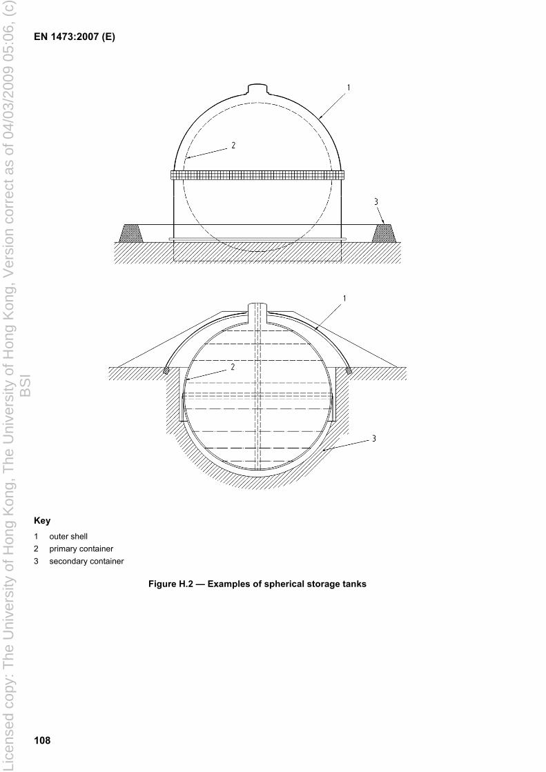
EN 1473:2007 (E)
108
Key 1 outer shell 2 primary container 3 secondary container
Figure H.2 — Examples of spherical storage tanks
Lice
nsed
cop
y: T
he U
nive
rsity
of H
ong
Kon
g, T
he U
nive
rsity
of H
ong
Kon
g, V
ersi
on c
orre
ct a
s of
04/
03/2
009
05:0
6, (
c)B
SI
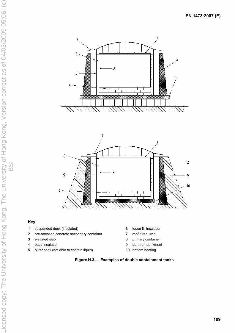
EN 1473:2007 (E)
109
Key 1 suspended deck (insulated) 6 loose fill insulation 2 pre-stressed concrete secondary container 7 roof if required 3 elevated slab 8 primary container 4 base insulation 9 earth embankment 5 outer shell (not able to contain liquid) 10 bottom heating
Figure H.3 — Examples of double containment tanks
Lice
nsed
cop
y: T
he U
nive
rsity
of H
ong
Kon
g, T
he U
nive
rsity
of H
ong
Kon
g, V
ersi
on c
orre
ct a
s of
04/
03/2
009
05:0
6, (
c)B
SI
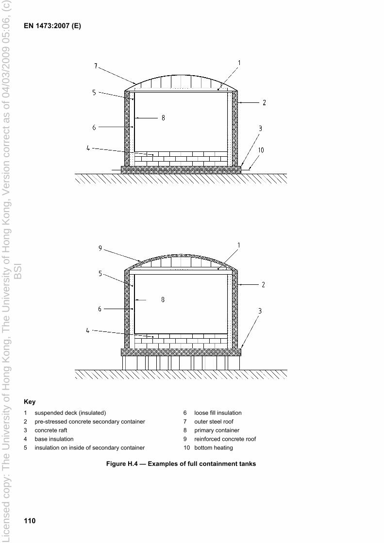
EN 1473:2007 (E)
110
Key 1 suspended deck (insulated) 6 loose fill insulation 2 pre-stressed concrete secondary container 7 outer steel roof 3 concrete raft 8 primary container 4 base insulation 9 reinforced concrete roof 5 insulation on inside of secondary container 10 bottom heating
Figure H.4 — Examples of full containment tanks
Lice
nsed
cop
y: T
he U
nive
rsity
of H
ong
Kon
g, T
he U
nive
rsity
of H
ong
Kon
g, V
ersi
on c
orre
ct a
s of
04/
03/2
009
05:0
6, (
c)B
SI
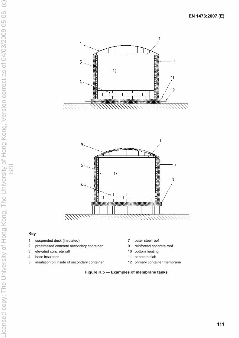
EN 1473:2007 (E)
111
Key 1 suspended deck (insulated) 7 outer steel roof 2 prestressed concrete secondary container 9 reinforced concrete roof 3 elevated concrete raft 10 bottom heating 4 base insulation 11 concrete slab 5 insulation on inside of secondary container 12 primary container membrane
Figure H.5 — Examples of membrane tanks
Lice
nsed
cop
y: T
he U
nive
rsity
of H
ong
Kon
g, T
he U
nive
rsity
of H
ong
Kon
g, V
ersi
on c
orre
ct a
s of
04/
03/2
009
05:0
6, (
c)B
SI
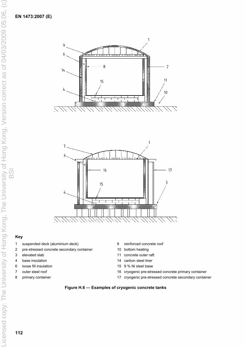
EN 1473:2007 (E)
112
Key 1 suspended deck (aluminium deck) 9 reinforced concrete roof 2 pre-stressed concrete secondary container 10 bottom heating 3 elevated slab 11 concrete outer raft 4 base insulation 14 carbon steel liner 6 loose fill insulation 15 9 % Ni steel base 7 outer steel roof 16 cryogenic pre-stressed concrete primary container 8 primary container 17 cryogenic pre-stressed concrete secondary container
Figure H.6 — Examples of cryogenic concrete tanks
Lice
nsed
cop
y: T
he U
nive
rsity
of H
ong
Kon
g, T
he U
nive
rsity
of H
ong
Kon
g, V
ersi
on c
orre
ct a
s of
04/
03/2
009
05:0
6, (
c)B
SI
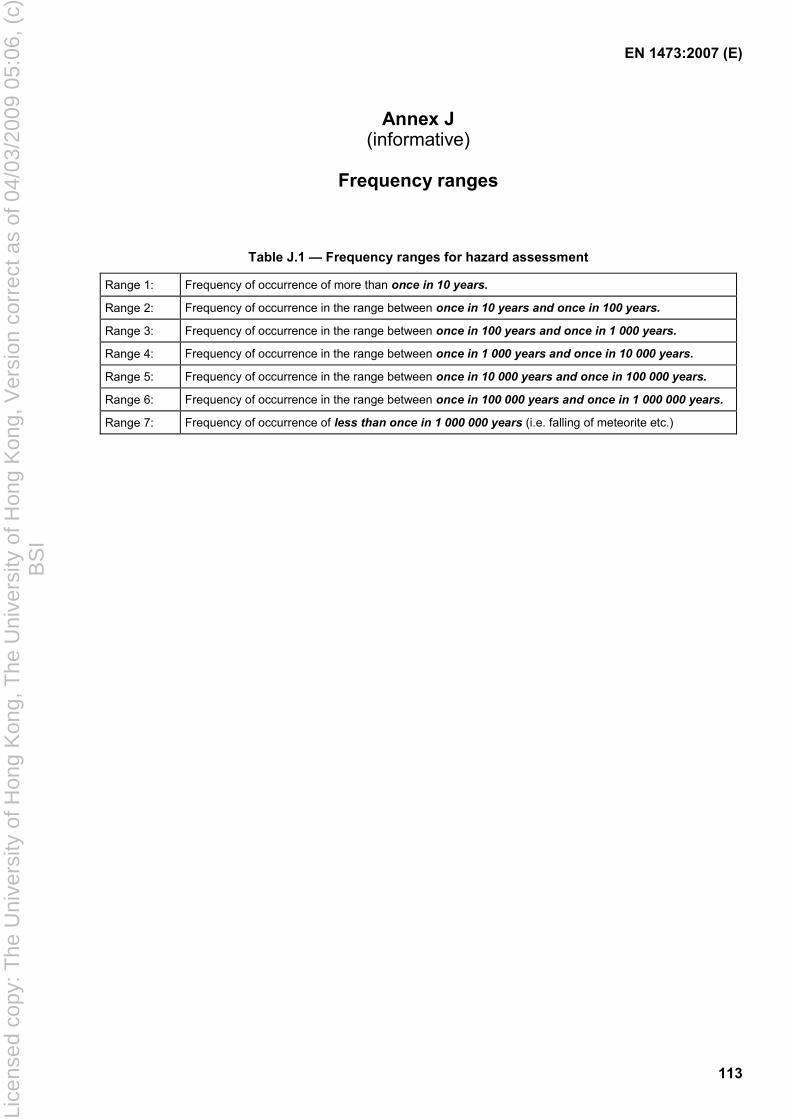
EN 1473:2007 (E)
113
Annex J (informative)
Frequency ranges
Table J.1 — Frequency ranges for hazard assessment
Range 1: Frequency of occurrence of more than once in 10 years. Range 2: Frequency of occurrence in the range between once in 10 years and once in 100 years. Range 3: Frequency of occurrence in the range between once in 100 years and once in 1 000 years. Range 4: Frequency of occurrence in the range between once in 1 000 years and once in 10 000 years. Range 5: Frequency of occurrence in the range between once in 10 000 years and once in 100 000 years. Range 6: Frequency of occurrence in the range between once in 100 000 years and once in 1 000 000 years. Range 7: Frequency of occurrence of less than once in 1 000 000 years (i.e. falling of meteorite etc.)
Lice
nsed
cop
y: T
he U
nive
rsity
of H
ong
Kon
g, T
he U
nive
rsity
of H
ong
Kon
g, V
ersi
on c
orre
ct a
s of
04/
03/2
009
05:0
6, (
c)B
SI
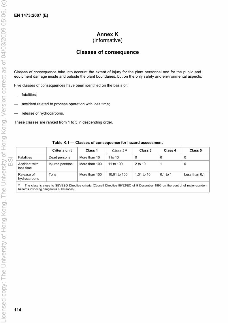
EN 1473:2007 (E)
114
Annex K (informative)
Classes of consequence
Classes of consequence take into account the extent of injury for the plant personnel and for the public and equipment damage inside and outside the plant boundaries, but on the only safety and environmental aspects.
Five classes of consequences have been identified on the basis of:
fatalities;
accident related to process operation with loss time;
release of hydrocarbons.
These classes are ranked from 1 to 5 in descending order.
Table K.1 — Classes of consequence for hazard assessment
Criteria unit Class 1 Class 2 a Class 3 Class 4 Class 5
Fatalities Dead persons More than 10 1 to 10 0 0 0
Accident with loss time
Injured persons More than 100 11 to 100 2 to 10 1 0
Release of hydrocarbons
Tons More than 100 10,01 to 100 1,01 to 10 0,1 to 1 Less than 0,1
a The class is close to SEVESO Directive criteria [Council Directive 96/82/EC of 9 December 1996 on the control of major-accident hazards involving dangerous substances].
Lice
nsed
cop
y: T
he U
nive
rsity
of H
ong
Kon
g, T
he U
nive
rsity
of H
ong
Kon
g, V
ersi
on c
orre
ct a
s of
04/
03/2
009
05:0
6, (
c)B
SI
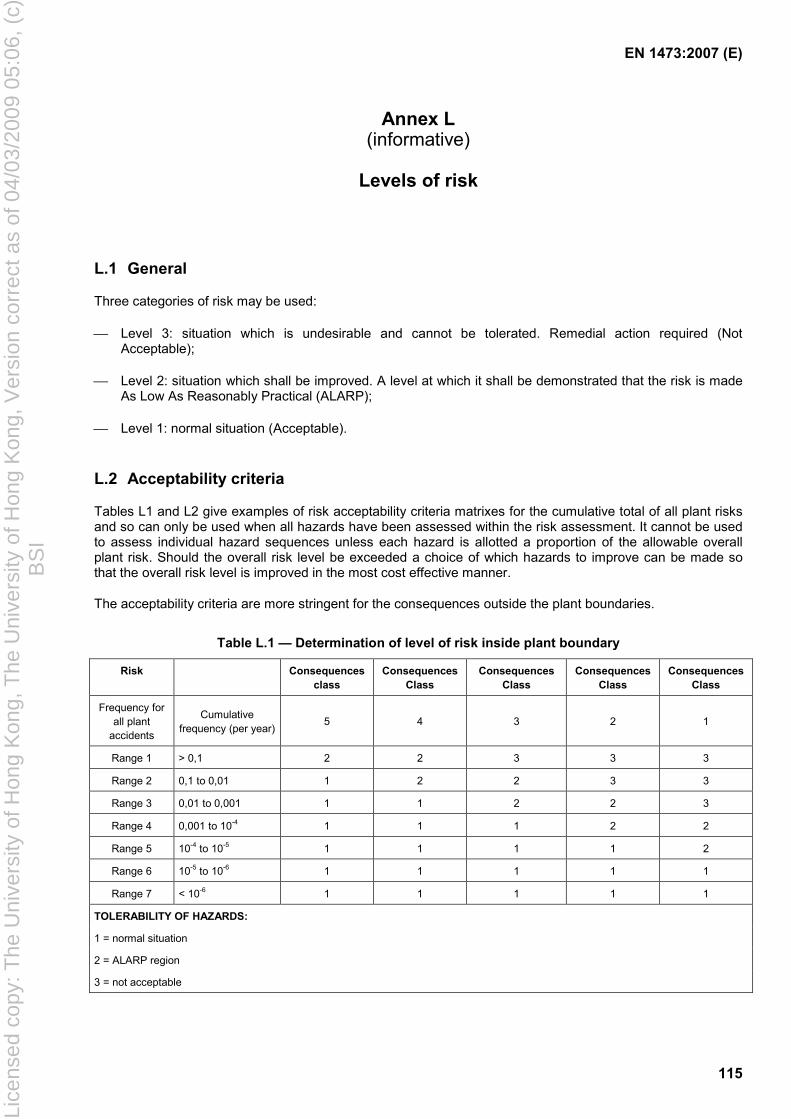
EN 1473:2007 (E)
115
Annex L (informative)
Levels of risk
L.1 General
Three categories of risk may be used:
Level 3: situation which is undesirable and cannot be tolerated. Remedial action required (Not Acceptable);
Level 2: situation which shall be improved. A level at which it shall be demonstrated that the risk is made As Low As Reasonably Practical (ALARP);
Level 1: normal situation (Acceptable).
L.2 Acceptability criteria
Tables L1 and L2 give examples of risk acceptability criteria matrixes for the cumulative total of all plant risks and so can only be used when all hazards have been assessed within the risk assessment. It cannot be used to assess individual hazard sequences unless each hazard is allotted a proportion of the allowable overall plant risk. Should the overall risk level be exceeded a choice of which hazards to improve can be made so that the overall risk level is improved in the most cost effective manner.
The acceptability criteria are more stringent for the consequences outside the plant boundaries.
Table L.1 — Determination of level of risk inside plant boundary
Risk Consequences class
Consequences Class
Consequences Class
Consequences Class
Consequences Class
Frequency for all plant
accidents
Cumulative frequency (per year)
5 4 3 2 1
Range 1 > 0,1 2 2 3 3 3
Range 2 0,1 to 0,01 1 2 2 3 3
Range 3 0,01 to 0,001 1 1 2 2 3
Range 4 0,001 to 10-4 1 1 1 2 2
Range 5 10-4 to 10-5 1 1 1 1 2
Range 6 10-5 to 10-6 1 1 1 1 1
Range 7 < 10-6 1 1 1 1 1
TOLERABILITY OF HAZARDS:
1 = normal situation
2 = ALARP region
3 = not acceptable
Lice
nsed
cop
y: T
he U
nive
rsity
of H
ong
Kon
g, T
he U
nive
rsity
of H
ong
Kon
g, V
ersi
on c
orre
ct a
s of
04/
03/2
009
05:0
6, (
c)B
SI
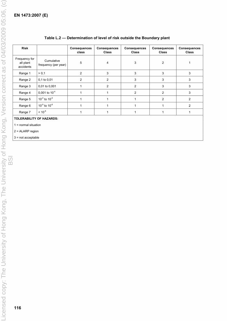
EN 1473:2007 (E)
116
Table L.2 — Determination of level of risk outside the Boundary plant
Risk Consequences class
Consequences Class
Consequences Class
Consequences Class
Consequences Class
Frequency for all plant
accidents
Cumulative frequency (per year) 5 4 3 2 1
Range 1 > 0,1 2 3 3 3 3
Range 2 0,1 to 0,01 2 2 3 3 3
Range 3 0,01 to 0,001 1 2 2 3 3
Range 4 0,001 to 10-4 1 1 2 2 3
Range 5 10-4 to 10-5 1 1 1 2 2
Range 6 10-5 to 10-6 1 1 1 1 2
Range 7 < 10-6 1 1 1 1 1
TOLERABILITY OF HAZARDS:
1 = normal situation
2 = ALARP region
3 = not acceptable
Lice
nsed
cop
y: T
he U
nive
rsity
of H
ong
Kon
g, T
he U
nive
rsity
of H
ong
Kon
g, V
ersi
on c
orre
ct a
s of
04/
03/2
009
05:0
6, (
c)B
SI
EN 1473:2007 (E)
117
Annex M (informative)
Typical process steps of liquefaction
M.1 Introduction
Liquefaction plant is considered to start at the inlet to the acid gas removal unit and to terminate at the inlet to the LNG (and other liquid hydrocarbon) rundown lines. Gas transmission, treatment upstream of acid gas removal and product and refrigerant storage are excluded from this annex. Descriptions of commonly used processes are given, however there is no implication that these are the best or only processing options.
M.2 Treatment of natural gas/extraction of acid gases
M.2.1 General
The purpose of the acid gas extraction unit is to reduce the CO2 and H2S content within the gas to be liquefied to values which are compatible with commercial and legal gas specifications and are compatible with cooling requirements (risk of solidification). Contents tolerated within the treated gas are:
CO2 < 100 × 10-6 by volume;
H2S < 4 × 10⁻⁶ by volume.
The selection of the treatment process will depend on the type and concentration of impurities to be removed. Commonly used processes are described below.
M.2.2 Absorption processes
M.2.2.1 Principle of operation
The principle of such processes is to absorb acid gases from the gas to be treated, by scrubbing with an absorption solution within a tray-type or packed-type absorber.
The absorbent solution can be:
either chemical (formation of a chemical compound which, on temperature rise, dissociates by releasing acid gases);
or physical (absorption brought about by pressure, which then, through lowering of pressure, allows the initial solution to be regenerated).
In certain processes, the absorption solution is a mixture of chemical and physical solvents.
Some absorption solutions contain additives designed to improve reactivity of the solvent, reduce risks of corrosion or prevent foaming.
M.2.2.2 Operating parameters/performance data
Design of an acid gas extraction plant requires knowledge of nominal values of the operating parameters of the plant which are listed below, and also the ranges of variation of such parameters:
Lice
nsed
cop
y: T
he U
nive
rsity
of H
ong
Kon
g, T
he U
nive
rsity
of H
ong
Kon
g, V
ersi
on c
orre
ct a
s of
04/
03/2
009
05:0
6, (
c)B
SI
EN 1473:2007 (E)
118
flow rate, pressure, temperature, composition and acid gas content of incoming natural gas entering the plant for treatment;
flow rate, pressure and acid gas content of treated natural gas leaving the plant;
absorption solution circulation rate and concentration.
In particular, the following values should be ensured by the process holder and/or the manufacturer:
flow rate of treated natural gas leaving the plant;
acid gas content of outgoing treated natural gas;
pressure drop on the natural gas circuit;
absorption solution concentration;
absorption solution circulation rate;
absorption solution losses;
consumption of utilities, for the rated operating conditions of the plant.
M.2.2.3 Particular features
Design of the plant should take account of certain features which are specific to this type of plant.
a) Risks of foaming in the absorber
Formation of foam inside the absorber brings about deterioration in the performance of the absorber and driving of foam (and therefore of absorption solution) with the treated gas as it leaves the over head of the absorber.
Foaming can occur for several reasons:
incorrect design or poor sizing of the absorber;
presence of solid particles in the solution;
presence of liquid hydrocarbons in the scrubbing solution.
The absorption solution should be filtered in order to prevent accumulation of solid particles.
The gas entering the absorber should not contain liquid hydrocarbons. It should furthermore be checked that there is no risk of condensation of hydrocarbons within the absorber. If the presence of liquid hydrocarbons in the absorption solution cannot be excluded, installation of a device for absorption of liquid hydrocarbons (passing at least part of the solution in circulation over a bed of activated carbon, for example) is recommended.
"Anti-foam" additive can be injected into the solution as long as its presence will not bring about secondary effects which impair operation of the plant.
b) Risks of corrosion
Under certain circumstances (such as high temperature or high acid gas concentration) absorption solutions can become corrosive to steel.
Lice
nsed
cop
y: T
he U
nive
rsity
of H
ong
Kon
g, T
he U
nive
rsity
of H
ong
Kon
g, V
ersi
on c
orre
ct a
s of
04/
03/2
009
05:0
6, (
c)B
SI
EN 1473:2007 (E)
119
In addition to weakening of the metal, corrosion residue promotes foaming in the absorber - hence the importance of proper selection of construction materials and heat treatment in order to prevent corrosion phenomena.
A corrosion inhibitor can be added to the solution as long as it does not bring about secondary effects which are harmful to operation of the plant.
M.2.3 Molecular sieve adsorption process
Molecular sieves, which are widely used for gas dehydration, have the property of adsorbing acid gases as well. However, the number of molecular sieve vessels to be installed, and the volume of flow of regeneration gas necessary, limit use of molecular sieves to natural gases with low acid gases content (less than 0,2 % by volume for large capacity LNG plants up to about 1,5 % by volume for LNG peak-shaving plants).
Please see information on dehydration units in M.3 below for use of a process of this type.
M.2.4 Other sulphur processes than H2S
In addition to H2S, the raw natural gas can contain other sulphur compounds (COS, mercaptans etc.) which are generally not removed by the acid gas removal treatment, while LNG specifications usually include a limit on total sulphur quantity. The concentration of such sulphur compounds in the natural gas can therefore need to be reduced.
The choice of process is related to the quantity and type of sulphur compounds present in the raw natural gas stream. Possible processes include cryogenic distillation (the sulphur compounds are removed during NGL extraction from the natural gas and definitively removed by treatment of the LPG) and on the molecular sieves used for dehydration.
M.3 Natural gas treatment/dehydration
M.3.1 General
The water content of treated gas should be less than 1 × 10⁻⁶ by volume. Dehydration of natural gas to be liquefied is generally carried out on molecular sieves. Activated alumina or silica gel can also be used.
M.3.2 Principle of operation
Dehydration is done by passing wet natural gas over a bed of molecular sieves. Molecular sieves are aluminosilicates of sodium, calcium or potassium with regular pore size crystalline structures which allow great selectivity concerning the size of molecules adsorbed and give high adsorption capacity.
A dehydration unit includes at least two dryers which contain molecular sieves. One is in adsorption while the other is in regeneration. Regeneration is carried out at high temperature (200 °C to 250 °C) by circulating dry gas which has been heated beforehand in a heater or a heat exchanger.
Regeneration can be carried out either at the same pressure as adsorption, using dry gas recycled through a compressor, or at low pressure.
In order to reduce the quantity of water to be removed from the gas by the molecular sieves, natural gas is generally cooled - while at the same time remaining above hydrate formation temperature - in such a way as to condense part of the water before passing over the molecular sieves.
Lice
nsed
cop
y: T
he U
nive
rsity
of H
ong
Kon
g, T
he U
nive
rsity
of H
ong
Kon
g, V
ersi
on c
orre
ct a
s of
04/
03/2
009
05:0
6, (
c)B
SI
EN 1473:2007 (E)
120
M.3.3 Operating parameters/performance data
Design of a dehydration plant requires knowledge of nominal values of the operating parameters of the plant which are listed below, and also the ranges of variation of such parameters:
flow rate, pressure, temperature, composition and water content of incoming natural gas entering the plant for dehydration;
flow rate, pressure and water content of dry natural gas leaving the plant;
flow rate and pressure of regeneration gas to the dryers;
temperature of hot regeneration gas;
duration of cycle.
In particular, the following values should be ensured by the process holder and/or the manufacturer, for the rated conditions of operation of the plant:
flow rate of dry natural gas leaving the plant;
pressure drop on the natural gas circuit;
water content of outgoing dry natural gas;
flow of regeneration gas to dryers;
temperature of hot regeneration gas;
life of molecular sieves.
M.3.4 Particular features
In order not to damage the crystalline structures of molecular sieves, it is necessary to protect them against any untimely arrival of liquid (acid gas removal solution, water or liquid hydrocarbons).
Attrition, which causes formation of molecular sieve dust can be minimised through careful control of the changes in regeneration gas temperature and, when regeneration is carried out at low pressure, by gradual de-pressurising and re-pressurisation.
Low points on pipe works where water could condense and then accumulate should be avoided.
The presence of molecular sieve dust can upset operation of valves and, therefore, it is necessary to take account of this when choosing the type of valve and positioning of valves.
Dry gas leaving the dryers should be carefully filtered (cartridge filters, generally) in order to prevent any entrainment of molecular sieve dust into the cryogenic exchangers of the liquefaction unit.
It is recommended to provide a standby period at the end of the regeneration phase of approximately 15 min to 30 min for export terminals and up to 10 min for peak-shaving plants. This period of time makes it possible for action to be taken in the event of mal-operation of automatic mechanisms or blockage of a valve.
M.4 Treatment of natural gas/removal of mercury
Certain natural gases can contain quantities of mercury. Mercury can, under certain conditions, be extremely corrosive to aluminium which is a metal widely used for construction of cryogenic exchangers and possibly
Lice
nsed
cop
y: T
he U
nive
rsity
of H
ong
Kon
g, T
he U
nive
rsity
of H
ong
Kon
g, V
ersi
on c
orre
ct a
s of
04/
03/2
009
05:0
6, (
c)B
SI
EN 1473:2007 (E)
121
certain other items of equipment. If the gas to be liquefied contains mercury, it is essential to remove it before the natural gas enters the liquefaction unit.
Extraction of mercury from natural gas is done by passing the gas through a reactor bed made up of sulphur, iodine or metal sulphide impregnated beads or pellets of high porosity alumina, activated carbon or molecular sieve. In general, the target specification at the outlet of the de-mercurisation unit shall be below 0,01 µg/m3 of mercury of gas measured at 1 013 mbar and at 0 °C.
This process is not regenerative. The absorbent mass should be replaced when it is saturated.
M.5 Natural gas liquefaction unit
M.5.1 General
The purpose of a liquefaction unit is to transform treated natural gas into liquefied natural gas (LNG) at its boiling temperature at atmospheric pressure, in order to permit its storage and transportation.
M.5.2 Principle of operation
M.5.2.1 Natural gas circuit and fractionation
Treated gas enters the liquefaction unit after acid gases, water and, if appropriate, mercury have been extracted. At this stage, however, the gas can still contain heavy and aromatic hydrocarbons. If not removed these components are liable to solidify in the course of cooling, gradually clogging the cryogenic exchangers and potentially relief valves. The natural gas is therefore cooled from ambient to LNG temperatures in two stages, generally designated as pre-cooling and liquefaction.
After pre-cooling the partially condensed natural gas is fractionated in such a way as to extract a C2+ cut. This C2+ cut contains all the undesirable (C5+) heavy hydrocarbons, and also ethane, propane and butane. A small part of these components might be used as make-up for refrigerant cycles, and surpluses might be extracted for marketing or re-injected into the natural gas to be liquefied. The higher the desired extraction rate is for ethane, propane and butane, the lower the temperature will be at which fractionation is to be carried out. If sulphur species such as mercaptans are removed at this stage, this can dictate the process conditions for fractionation.
Natural gas thus cleaned of its heavier hydrocarbons can then be liquefied. The higher the pressure of the natural gas, the smaller the work necessary for liquefaction. Therefore every effort should be made to operate at the maximum pressure compatible with the heavy hydrocarbon extraction.
Following condensation at high pressure, the liquefied natural gas shall be sub-cooled to avoid excessive vaporisation following expansion to the atmospheric pressure of the storage tanks. Two approaches are possible:
if the natural gas does not contain much nitrogen (less than 1,5 mole % in general), carry out complete sub-cooling of the LNG down to an enthalpy level equivalent to a temperature slightly below the bubble point temperature (approximately − 160 °C) at atmospheric pressure. The sub cooled LNG can then be sent directly to the storage tanks;
carry out partial sub-cooling (approximately − 150 °C) followed by expansion in a flash drum at a pressure which is slightly above atmospheric; the flash gas produced on expansion is re-compressed, in general for supplying the fuel gas system, whereas the LNG contained in the flash drum is sent to the tanks using a pump. In LNG peak-shaving plants, the final flash can be done directly in the vapour space of the tank.
Complete sub-cooling requires additional liquefaction energy consumption but avoids the need for LNG pumps and a flash gas compressor. If nitrogen needs to be removed to obtain the desired LNG quality this operation is done in the final flash, or, for high nitrogen contents, in a low temperature fractionating column.
Lice
nsed
cop
y: T
he U
nive
rsity
of H
ong
Kon
g, T
he U
nive
rsity
of H
ong
Kon
g, V
ersi
on c
orre
ct a
s of
04/
03/2
009
05:0
6, (
c)B
SI
EN 1473:2007 (E)
122
M.5.2.2 Refrigeration cycles
The purpose of the refrigeration cycle(s) is to extract sensible and latent heat from the natural gas to transform it from the gaseous state at high pressure to the liquid state at atmospheric pressure.
Liquefaction of natural gas requires production of refrigerating power from ambient temperature to approximately − 150 °C to − 160 °C.
Base-load liquefaction plants generally use two refrigeration cycles working in cascade, whereas only one refrigeration cycle is generally preferred in LNG peak-shaving plants.
A refrigerant compressor can be driven by gas turbine, steam turbine or electric motor. Refrigerants are made up either of a mixture of light hydrocarbons (with, if appropriate, nitrogen in order to obtain the lowest temperatures), or by a pure substance such as propane, for example.
M.5.3 Operating parameters/performance data
Design of a natural gas liquefaction unit requires knowledge of nominal values of the operating parameters of the unit which are listed below, and also the ranges of variation of such parameters:
flow rate, temperature and the detailed composition of the natural gas entering the unit;
flow rate of liquefied natural gas leaving the unit;
pressure, temperature and composition of outgoing LNG;
conditions: temperature, pressure, flow rate and composition of other streams leaving the unit (C5+ cut, ethane, propane, butane, gasoline and flash gas if appropriate);
conditions of the different utilities available and, most especially, temperature of the cooling air or water;
extraction rates of commercial ethane, propane and butane.
In particular, the following values should be guaranteed by the process licenser and/or the manufacturer, for the rated operating conditions of the plant:
the flow rate of LNG leaving the unit;
the temperature of the outgoing LNG;
the composition of the outgoing LNG;
the flow rate, pressure, temperature and composition of commercial ethane, propane and butane, as appropriate;
utility consumption's.
M.5.4 Low temperatures
The fact of working at low temperature, on the one hand, and of having units which are often of very high capacity, on the other, leads to characteristics which are specific to this type of plant.
Design temperatures of equipment and of pipe-work require the selected construction materials to be compatible with the temperatures encountered in both normal and transient operation (start-up, shutdown, upset) of the unit.
Three categories of steel materials are generally provided for (see EN 1160 for details):
Lice
nsed
cop
y: T
he U
nive
rsity
of H
ong
Kon
g, T
he U
nive
rsity
of H
ong
Kon
g, V
ersi
on c
orre
ct a
s of
04/
03/2
009
05:0
6, (
c)B
SI
EN 1473:2007 (E)
123
carbon steel for non cryogenic low temperatures (typically > − 46 °C);
3,5 % nickel alloy steel for design temperatures > − 104 °C;
9 % nickel alloy steel or stainless steel for design temperatures > − 196 °C.
These categories can eventually be extended where the design temperature can only be obtained by depressurization and where steps are taken to avoid re-pressurisation of cold equipment.
As in any low temperature plant, it is necessary to install means for careful drying of circuits prior to starting in order to eliminate any trace of moisture in the cryogenic circuits as a whole.
Make-up for coolants should be perfectly dry and shall not contain any component liable to solidify at the temperatures encountered.
M.5.5 Specific equipment
M.5.5.1 General
Natural gas liquefaction units contain specific items of equipment, cryogenic exchangers, turbo-compression sets and cooling systems, which are particularly large in LNG export terminals.
M.5.5.2 Cryogenic exchangers
The design of cryogenic exchangers of LNG units should comply with a number of requirements:
presence of several warm side fluids (refrigerants at various pressure stages, vapour and/or liquid, natural gas) flowing counter current (and/or cross current) to lower pressure refrigerants which are generally bi-phase;
large temperature differences for each fluid across the heat exchanger;
small temperature differences between the warm and the cold circuits throughout the heat exchanger;
significant metal temperature gradients within the heat exchanger;
low temperatures;
very large amounts of heat exchanged;
high differential pressures;
high mass flow rates.
Two types of equipment enable the requirements as a whole to be met: spool-wound heat exchangers and plate-fin heat exchangers.
Spool-wound heat exchangers are widely used in large capacity LNG plants. They are made up of a succession of layers of aluminium (or stainless steel) tubes helically wound around a core. Fluids at high pressure to be condensed or sub-cooled circulate inside the tubes, whereas the coolant is vaporised at low pressure in the shell outside the tubes. Such a design allows exchangers with very large unit heat transfer areas to be built.
Aluminium brazed plate fin exchangers are widely used in the cryogenic field for gas separation and/or gas liquefaction.
Lice
nsed
cop
y: T
he U
nive
rsity
of H
ong
Kon
g, T
he U
nive
rsity
of H
ong
Kon
g, V
ersi
on c
orre
ct a
s of
04/
03/2
009
05:0
6, (
c)B
SI
EN 1473:2007 (E)
124
The design of these exchangers results in a large heat transfer area within the relatively small volume of a core.
Brazed plate fin heat exchangers are manufactured as modular cores of up to a maximum size of approximately 12 m3. For high pressure service, the maximum core size should be further limited to ensure the mechanical integrity of the heat exchanger. Large heat transfer duties need therefore to be achieved by the assembly of several cores in parallel, usually in perlite filled cold boxes.
Other plate-type heat exchangers, using welded stainless steel plates, presently used in hot services, could be adapted to cryogenic services in LNG units.
M.5.5.3 Compression systems
M.5.5.3.1 General
LNG export terminals require the use of very powerful refrigerant compression systems.
M.5.5.3.2 Refrigerant compressors
Centrifugal compressors are the type most widely used in the LNG industry. However the quest for increased LNG export terminal unit capacity has led to the increased use of axial type compressors when the compressor suction flow exceeds centrifugal compressor capacity. Furthermore, axial compressors have a better efficiency than centrifugal machines.
Careful design and manufacture of compressor anti-surge devices is required. Indeed, the power dissipated in such devices is so high that aero-elasticity and excessive stress can arise leading to metal cracks and ruptures if not properly taken into account.
M.5.5.3.3 Drivers
Many existing LNG export terminals use steam-turbines as refrigeration compressor drivers. Steam turbines are available in a very large power range and have excellent reliability.
Gas turbines are increasingly preferred as refrigeration compressor drivers resulting from several technical factors:
no high pressure steam is required (with the corresponding boiler feed water treatment);
large reduction of cooling water consumption;
it is possible to increase the overall efficiency by heat recovery on the gas turbine exhaust gases.
The influence of ambient air temperature variations on the power delivered by the gas turbine (power decreases when air temperature increases) needs to be taken into account.
Two-shaft gas turbines are commonly used as compressor drivers because of the advantages of operating at variable speed.
If the power requirement exceeds the capability of two-shaft gas turbines, it is possible to use large single shaft gas turbines originally built for electrical power generation and where operation at constant speed is no handicap. Adjustment of the composition of the refrigerant mixture during design and if required during operation can be made to fit the constant compressor speed. Start-up requires special attention.
In all cases, because of the importance of the refrigerant compression systems for the good operation of LNG units, such equipment should be designed, manufactured, operated and maintained very carefully in order to achieve maximum reliability.
Lice
nsed
cop
y: T
he U
nive
rsity
of H
ong
Kon
g, T
he U
nive
rsity
of H
ong
Kon
g, V
ersi
on c
orre
ct a
s of
04/
03/2
009
05:0
6, (
c)B
SI
EN 1473:2007 (E)
125
M.5.5.4 Cooling system
In base load liquefaction trains, a huge heat duty shall be rejected to the environment via the cooling system.
As such plants are most frequently located on the coast for transportation of LNG by tanker, sea water is frequently used as the cooling medium.
The volume flow of sea water necessary, particularly when refrigerant compressors are driven by steam turbines, can justify the choice of a siphoned sea water system which permits a significant reduction in pumping energy and reduces the risks of corrosion, by lowering the oxygen content in the cooling system. In a sea water circuit particular attention should be paid to corrosion and to the risk of development of living organisms (algae, mussels etc.) within the circuit.
If site conditions (such as elevation or sea water quality) make it uneconomic to use sea water as a cooling fluid, it is possible to use either a closed fresh water circuit with cooling tower or air-cooled heat exchangers. Problems can arise because of development of bacteria in fresh water circuits. This should be prevented by appropriate water treatment.
Lice
nsed
cop
y: T
he U
nive
rsity
of H
ong
Kon
g, T
he U
nive
rsity
of H
ong
Kon
g, V
ersi
on c
orre
ct a
s of
04/
03/2
009
05:0
6, (
c)B
SI
EN 1473:2007 (E)
126
Annex N (informative)
Odourant systems
N.1 Odourants in general
Odourisation is achieved by the addition of an odourant which is typically a blend of volatile organic sulphur compounds e.g. ethyl mercaptan, tertiary butyl mercaptan, methyl ethyl sulphide and diethyl sulphide, or a single component such as tetrahydrothiophene. Odourant liquids are volatile, flammable and of extremely noxious smell.
In their concentrated form most of those products are toxic.
N2 Odourant systems requirements
N.2.1 General
The odorising plant generally consists of a storage tank, smaller feed tanks, pumps and associated valves and pipe-work. The plant should be designed for ease of maintenance and operation and protection from possible impact damage. Care should be taken that materials used in the construction are compatible with odourant. In particular, copper and copper based alloys, polyethylene and polypropylene and butyl and natural rubber are attacked by liquid odourants and should not be used in the construction of this equipment. Welded pipe connections should be used whenever possible.
During normal operations there should be no emission of odourant to the atmosphere and the system shall be designed to eliminate and minimise all possible emissions.
The tanks and injection equipment should be located within a bunded area with provision for the drainage of rainwater. It should not be possible for spills or leaks to accumulate under storage vessels or equipment.
N.2.2 Storage
Liquid odourant may be stored in fixed tanks with a road tanker off-loading point, or supplied in stainless steel transportable containers with international approval for the transport of dangerous goods under UN 1A1W/X2.0/900. This latter method enables connection directly to injection equipment with dry break couplings, and flexible braided PTFE hoses, thereby avoiding the need to transfer odourant from a road tanker to the fixed storage tank and reducing the risk of accidental spillage.
It is recommended that there should be the minimum number of pipe connections to the storage tank below the maximum liquid content level of the tank.
An oxygen free gas blanket compatible with the selected odourant should be provided above the liquid odourant.
N.2.3 Odourant pumps and valves
It is recommended to use pumped odourant plant to odorise large volumes of gas. Where volumes of gas to be odorised are small, the use of an evaporative type of odourant plant can be considered.
Odourant pumps should be of a design, which minimises the possibility of leakage.
Pumps should have filters on the suction side and be capable of handling the whole range of flows.
Lice
nsed
cop
y: T
he U
nive
rsity
of H
ong
Kon
g, T
he U
nive
rsity
of H
ong
Kon
g, V
ersi
on c
orre
ct a
s of
04/
03/2
009
05:0
6, (
c)B
SI
EN 1473:2007 (E)
127
Piping should be seamless stainless steel and connections, wherever possible, should be welded.
All valves, flanges and fittings should be designed in accordance with EN 1092-1, EN 1759-1, EN 1514 and EN 12560.
N.3 Odourant handling
N.3.1 General
The precautions for odourant handling are those of any low flash point material. Additionally, owing to its pungency and toxicity see N.6 safety of personnel.
N.3.2 Delivery
Inert gas and methanol should be available to flush and purge the delivery hose and associated equipment if bulk transfer is to be undertaken.
Spillage trays, absorbent and decontamination equipment should be available at the tanker-unloading bay.
Self-sealing couplings should be used on the connections from the delivery vehicle, designed to close when the hose is disconnected.
The tanker should be connected to a static earthing point, temporarily, to discharge any accumulated electrical charge. The delivery hose should be electrically bonded to the bulk storage tank.
A vapour return system between delivery and storage tanks should normally be used for bulk transfer. If not a flare system or other means of disposal such as connection to the boil-off system can be considered.
N.3.3 Flushing and purging
All equipment should be decontaminated prior to dismantling for maintenance or inspection by draining or pumping liquid odourant from the equipment then flushing with methanol or other appropriate medium. After pumping the residual methanol/odourant, vapour can be purged with natural gas and finally inert gas to flare or into a suitable low-pressure line such as the boil-off system. Work should be covered by specially prepared procedures.
N.4 Odourant injection
The facility should be designed to be operable throughout the range of natural gas pressures, which can be seen at the injection point. Spraying nozzles should be sized to suit the full range of gas flow rate; if needed, several nozzles can be installed with appropriate automatic control to maintain a constant ratio of odourant to gas.
The injection stream itself should contain at least two pumps in parallel, one operational and the other standby (depending on the flow range required, a number of differently sized pumps may be used).
The injection rate should be closely monitored and controlled to ensure the minimum degree of odourisation is always achieved. It is recommended that the injection rate should be controlled by the signal from the gas flow meters.
The amount of odourant in the gas, if required, can be measured as follows:
by automatic sulphur titration which continuously measures the total sulphur of a flowing sample of the odorised gas;
Lice
nsed
cop
y: T
he U
nive
rsity
of H
ong
Kon
g, T
he U
nive
rsity
of H
ong
Kon
g, V
ersi
on c
orre
ct a
s of
04/
03/2
009
05:0
6, (
c)B
SI
EN 1473:2007 (E)
128
by checks of the odorised gas using a sulphur chromatograph.
N.5 Odourant leakage
A spill or leak of gas odourant results in an obnoxious odour, which – unless promptly neutralised – usually leads to employee and neighbour complaints. It is important that, if spills or leaks occur, the odourants are promptly neutralised and the odour masked. There are several agents available for this and proven methods for effectively handling the situation (see the Material Safety Data-Sheets for advice on clean up).
An effective method of neutralisation is based on converting the spilled odourant to a relatively low odour disulphide, through chemical oxidation. This may be achieved by spraying or flooding the spill area with a dilute bleach solution. Either sodium hypochlorite or calcium hypochlorite in dilute solution in water may be used. Dilute solutions are more effective than commercial or concentrated solution; for example, fifty litres of a ½ % solution is generally much more effective than 5 litres of a 5 % solution.
Because the chemical oxidation is not instantaneous, it is recommended that an odour-masking agent be applied along with the dilute bleach solution.
Use of dry calcium hypochlorite powder on a concentrated odourant should be avoided because the heat of the exothermic reaction may cause ignition of the organic mercaptan in the odourant.
Spilled liquid should be absorbed using dry sand or other recommended inert absorbent, neutralised and placed in sealed drums for proper disposal. A spillage of liquid odourant can also be blanketed with fire-fighting foam in order to reduce the evaporation rate.
It should be noted that the precise source of leakage could be difficult to identify as the highly volatile nature of odourant can result in rapid evaporation leaving no visible signs. Odourants have an “odour platform”, whereby the concentration in air can increase significantly without any noticeable increase in smell.
N.6 Safety of personnel
The Material Safety Data-Sheets for the odourant should be consulted for advice on the personal protection equipment required for the operators to safely handle the material. As a minimum, in any operation involving odourant, operators shall wear PVC gloves, eye protection and impervious clothing, which is readily decontaminated after use.
If a spillage of odourant occurs, personnel required to work in the area should wear self-contained breathing apparatus together with the above protective clothing.
If an operator is splashed with odourant, any contaminated clothing should be removed and skin washed with running water. A doctor should examine all eye splashes.
Safety shower and eyewash should be installed in the vicinity of the odourant handling area.
Lice
nsed
cop
y: T
he U
nive
rsity
of H
ong
Kon
g, T
he U
nive
rsity
of H
ong
Kon
g, V
ersi
on c
orre
ct a
s of
04/
03/2
009
05:0
6, (
c)B
SI
EN 1473:2007 (E)
129
Bibliography
[1] "Atmospheric diffusion", F. PASQUILL and F.B. SMITH third edition, Ellis Horwood Series Environment Science
[2] "Liquefied Petroleum Gas – Large bulk pressure storage and refrigerated LPG" The Institute of Petroleum, London, Feb. 1987
[3] "Guide for pressure-relieving and depressuring systems", API recommended practice n° 521, second edition, Sept. 1982
[4] "Maîtrise de l'urbanisation — La prise en compte des effets thermique, mécanique et toxique", Joëlle Jarry, Sécurité revue de préventique n° 15 Août septembre 1994
[5] "The multi energy method, a framework for vapour explosion blast prediction" A.C. van den BERG, Journal of Hazardous Materials, 12, 1985
[6] "Analyses des explosions air-hydrocarbure en milieu libre, étude déterministe et probabiliste de scénarios d'accident – Prévision des effets de surpression" (Analysis of unconfined air-hydrocarbon explosion, deterministic and probabilistic studies of accident scenarios – Prediction of the over pressure effects) A. LANNOY, Bulletin de la Direction des Études et Recherches EDF, Série A ISSN0013-449X, Octobre 1984
[7] GAP 2.5.1, Fire proofing for hydrocarbon fire exposures
[8] GAP 2.5.2, Oil and chemical plant layout and spacing
[9] GAP 8.0.1.1, Oil and chemical properties loss potential estimation Guide
[10] API RP 520 (all parts) Sizing, selection and installation of pressure-relieving devices in refineries
[11] IEC 60364 (all parts), Electrical installations of buildings/Low voltage electrical installations
[12] “ATEX” European Directive [Directive 1999/92/EC of the European Parliament and of the Council of 16 December 1999 on minimum requirements for improving the safety and health protection of workers potentially at risk from explosive atmospheres]
[13] IP15, Area Classification code for installation handling flammable fluids Part 15, 2d edition (2002), by the Institute of Petroleum)
[14] NFPA 921, Guide for Fire and Explosion Investigations
[15] LNG operations in Port Areas: SIGTTO
[16] Site selection and design for LNG Ports and jetties: SIGTTO
[17] NF C 17 100, Protection contre la foudre — Protection des structures contre la foudre — Installation de paratonnerres (Protection of structures against lightning — Installation of lighting Protective system).
[18] International Code for the Construction and Equipment of Ships Carrying Liquefied Gases in Bulk, (IGC Code), IMO.
[19] TNO Dutch experimental program on heat radiation from fires (report 79-0263).
[20] BS 5970, Code of practice for thermal insulation of pipework and equipment in the temperature range – 100 °C to 870 °C
Lice
nsed
cop
y: T
he U
nive
rsity
of H
ong
Kon
g, T
he U
nive
rsity
of H
ong
Kon
g, V
ersi
on c
orre
ct a
s of
04/
03/2
009
05:0
6, (
c)B
SI
EN 1473:2007 (E)
130
[21] VDI 2055, Thermal insulation for heated and refrigerated industrial and domestic installations — Calculations, guarantees, measuring and testing methods, quality assurance, supply conditions
[22] BS 6349, Maritime structures
[23] 10CFR100 appendix A to Part 100 — Seismic and Geologic Siting Criteria for Nuclear Power Plants
[24] The bulk Transfer of Dangerous Liquids and Gases between ship and shore
[25] BS 6656, Assessment of inadvertent ignition of flammable atmospheres by radio frequency radiation — Guide
[26] International Safety Guide for Oil Tanker and Terminal (OCMF/ICS/IAPH)
[27] BS 6651, Code of practice for protection of structures against lightning
[28] GAP 2.5.2 A : Hazard Classification of Process operations for spacing requirements
[29] BS 1722-10, Fences. Specification for strained wire and wire mesh netting fences
[30] International Ship and Port Facility Security Code (ISPS-Code) – International Maritime Organization (IMO)
[31] API 2218 Fireproofing Practices in Petroleum and Petrochemical Processing Plants
[32] Last developments in Rapid Phase Transition knowledge and modelling techniques D. Nédelka (Gaz de France), V. Sauter (Gaz de France), J. Goanvic (Total), R. Ohba (Mitsubishi Heavy Industries) OTC 15228 presented at the 2003 Offshore Technology Conference held in Houston, Texas, U.S.A., 5–8 May 2003.
[33] LNG Journal article in two parts:
1) May 2005 (pages 21-24), LNG-Water Rapid Phase Transition: Part1 - A literature Review
2) July-august 2005 (pages 28-30).LNG-Water Rapid Phase Transition: Part2 - Incident Analysis
[34] OSHA Occupational Safety and Health Administration
[35] EN 823, Thermal insulating products for building applications — Determination of thickness
[36] EN 1050, Safety of machinery — Principles for risk assessment
[37] EN 1759-1, Flanges and their joints — Circular flanges for pipes, valves, fittings and accessories, Class designated — Part 1: Steel flanges, NPS ½ to 24
[38] EN 12483, Liquid pumps — Pump units with frequency inverters — Guarantee and compatibility tests
[39] EN 12560-1, Flanges and their joints — Gaskets for Class-designated flanges — Part 1: Non-metallic flat gaskets with or without inserts
[40] EN 12560-2, Flanges and their joints — Gaskets for Class-designated flanges — Part 2: Spiral wound gaskets for use with steel flanges
[41] EN 12560-3, Flanges and their joints — Gaskets for Class-designated flanges — Part 3: Non-metallic PTFE envelope gaskets
[42] EN 12560-4, Flanges and their joints — Gaskets for Class-designated flanges — Part 4: Corrugated, flat or grooved metallic and filled metallic gaskets for use with steel flanges
Lice
nsed
cop
y: T
he U
nive
rsity
of H
ong
Kon
g, T
he U
nive
rsity
of H
ong
Kon
g, V
ersi
on c
orre
ct a
s of
04/
03/2
009
05:0
6, (
c)B
SI
EN 1473:2007 (E)
131
[43] EN 12560-5, Flanges and their joints — Gaskets for Class-designated flanges — Part 5: Metallic ring joint gaskets for use with steel flanges
[44] EN 12560-6, Flanges and their joints — Gaskets for Class-designated flanges — Part 6: Covered serrated metal gaskets for use with steel flanges
[45] EN 13645, Installations and equipment for liquefied natural gas — Design of onshore installations with a storage capacity between 5 t and 200 t
[46] EN 13766, Thermoplastic multi-layer (non-vulcanized) hoses and hose assemblies for the transfer of liquid petroleum gas and liquefied natural gas — Specification
[47] EN 61508 (all parts), Functionnal safety of electrical/electronical/programmable electronic safety-related systems
[48] EN 61800 (all parts), Adjustable speed electrical power drive systems
[49] EN 61779-1, Electrical apparatus for the detection and measurement of flammable gases — Part 1: General requirements and test methods (IEC 61779-1:1998, modified)
[50] EN 61779-4, Electrical apparatus for the detection and measurement of flammable gases — Part 4: Performance requirements for group II apparatus indicating a volume fraction up to 100 % lower explosive limit (IEC 61779-4:1998, modified)
[51] EN ISO 5199, Technical specifications for centrifugal pumps — Class II (ISO 5199:2002)
[52] EN ISO 9000, Quality management systems — Fundamentals and vocabulary (ISO 9000:2005)
[53] EN ISO 9906, Rotodynamic pumps — Hydraulic performance acceptance tests — Grades 1 and 2 (ISO 9906:1999)
[54] EN ISO 14001, Environmental management systems — Requirements with guidance for use (ISO 14001:2004)
[55] ISO 15664, Acoustics — Noise control design procedures for open plant
Lice
nsed
cop
y: T
he U
nive
rsity
of H
ong
Kon
g, T
he U
nive
rsity
of H
ong
Kon
g, V
ersi
on c
orre
ct a
s of
04/
03/2
009
05:0
6, (
c)B
SI
Lice
nsed
cop
y: T
he U
nive
rsity
of H
ong
Kon
g, T
he U
nive
rsity
of H
ong
Kon
g, V
ersi
on c
orre
ct a
s of
04/
03/2
009
05:0
6, (
c)
BS EN 1473:2007
BS
I
BSI389 Chiswick High RoadLondonW4 4AL
BSI — British Standards InstitutionBSI is the independent national body responsible for preparing British Standards. It presents the UK view on standards in Europe and at the international level. It is incorporated by Royal Charter.
Revisions
British Standards are updated by amendment or revision. Users of British Standards should make sure that they possess the latest amendments or editions.
It is the constant aim of BSI to improve the quality of our products and services. We would be grateful if anyone finding an inaccuracy or ambiguity while using this British Standard would inform the Secretary of the technical committee responsible, the identity of which can be found on the inside front cover. Tel: +44 (0)20 8996 9000. Fax: +44 (0)20 8996 7400.
BSI offers members an individual updating service called PLUS which ensures that subscribers automatically receive the latest editions of standards.
Buying standards
Orders for all BSI, international and foreign standards publications should be addressed to Customer Services. Tel: +44 (0)20 8996 9001. Fax: +44 (0)20 8996 7001. Email: [email protected]. Standards are also available from the BSI website at http://www.bsi-global.com.
In response to orders for international standards, it is BSI policy to supply the BSI implementation of those that have been published as British Standards, unless otherwise requested.
Information on standards
BSI provides a wide range of information on national, European and international standards through its Library and its Technical Help to Exporters Service. Various BSI electronic information services are also available which give details on all its products and services. Contact the Information Centre. Tel: +44 (0)20 8996 7111. Fax: +44 (0)20 8996 7048. Email: [email protected].
Subscribing members of BSI are kept up to date with standards developments and receive substantial discounts on the purchase price of standards. For details of these and other benefits contact Membership Administration. Tel: +44 (0)20 8996 7002. Fax: +44 (0)20 8996 7001. Email: [email protected].
Information regarding online access to British Standards via British Standards Online can be found at http://www.bsi-global.com/bsonline.
Further information about BSI is available on the BSI website at http://www.bsi-global.com.
Copyright
Copyright subsists in all BSI publications. BSI also holds the copyright, in the UK, of the publications of the international standardization bodies. Except as permitted under the Copyright, Designs and Patents Act 1988 no extract may be reproduced, stored in a retrieval system or transmitted in any form or by any means – electronic, photocopying, recording or otherwise – without prior written permission from BSI.
This does not preclude the free use, in the course of implementing the standard, of necessary details such as symbols, and size, type or grade designations. If these details are to be used for any other purpose than implementation then the prior written permission of BSI must be obtained.
Details and advice can be obtained from the Copyright & Licensing Manager. Tel: +44 (0)20 8996 7070. Fax: +44 (0)20 8996 7553. Email: [email protected].