Embed Size (px)
Citation preview
11 / 40
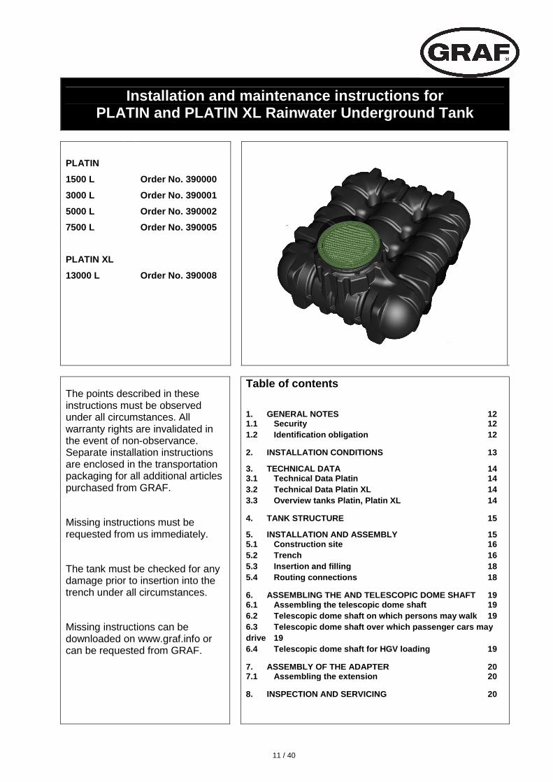
Installation and maintenance instructions for PLATIN and PLATIN XL Rainwater Underground Tank
PLATIN
1500 L
3000 L
5000 L
7500 L
PLATIN XL
13000 L
Order No. 390000
Order No. 390001
Order No. 390002
Order No. 390005
Order No. 390008
The points described in these instructions must be observed under all circumstances. All warranty rights are invalidated in the event of non-observance. Separate installation instructions are enclosed in the transportation packaging for all additional articles purchased from GRAF.
Missing instructions must be requested from us immediately.
The tank must be checked for any damage prior to insertion into the trench under all circumstances.
Missing instructions can be downloaded on www.graf.info or can be requested from GRAF.
Table of contents
1. GENERAL NOTES 12 1.1 Security 12 1.2 Identification obligation 12
2. INSTALLATION CONDITIONS 13
3. TECHNICAL DATA 14 3.1 Technical Data Platin 14 3.2 Technical Data Platin XL 14 3.3 Overview tanks Platin, Platin XL 14
4. TANK STRUCTURE 15
5. INSTALLATION AND ASSEMBLY 15 5.1 Construction site 16 5.2 Trench 16 5.3 Insertion and filling 18 5.4 Routing connections 18
6. ASSEMBLING THE AND TELESCOPIC DOME SHAFT 196.1 Assembling the telescopic dome shaft 196.2 Telescopic dome shaft on which persons may walk 19 6.3 Telescopic dome shaft over which passenger cars may drive 19 6.4 Telescopic dome shaft for HGV loading 19
7. ASSEMBLY OF THE ADAPTER 20 7.1 Assembling the extension 20
8. INSPECTION AND SERVICING 20
12 / 40
1. General notes
1.1 Security
The relevant accident prevention regulations according to BGV C22 must be observed during all work. Particularly when walking on the tanks, a 2nd person is required to secure the tank.
The relevant regulations and standards must additionally be taken into consideration during installation, assembly, servicing, repair, etc. Relevant notes can be found in the corresponding sections of these instructions.
During all work on the system or parts of the system, the entire system must always be rendered inoperable and secured to prevent unauthorised reactivation.
Except in the event of work carried out in the tank, the cover of the tank must always be kept sealed, as this otherwise constitutes a maximum risk of accident. The rain protection installed on delivery is merely transportation packaging. It cannot be walked on and is not child-proof; it must be replaced with a suitable cover immediately following delivery (telescopic dome shaft with corresponding cover)!
Only original GRAF covers or covers approved in writing by GRAF must be used.
GRAF offers an extensive range of accessories, all of which are designed to match each other and which can be extended to form complete systems. The use of other accessories may lead to impediments to the system's functional capability, therefore invalidating liability for resulting damage.
1.2 Identification obligation
All service water pipes and outlets must be identified in writing with the words "Not drinking water " or in the form of images (DIN 1988 Part 2, Para. 3.3.2.) in order to avoid inadvertent connection with the drinking water mains even after a number of years. Mix-ups, e.g. by children, may still occur even in the case of correct identification. All service water extraction points must therefore be installed with valves with child-proof locks .
13 / 40
455-655 455-755
Teleskop-DomschachtMini
Teleskop-DomschachtMaxi / Guss
max. 1200
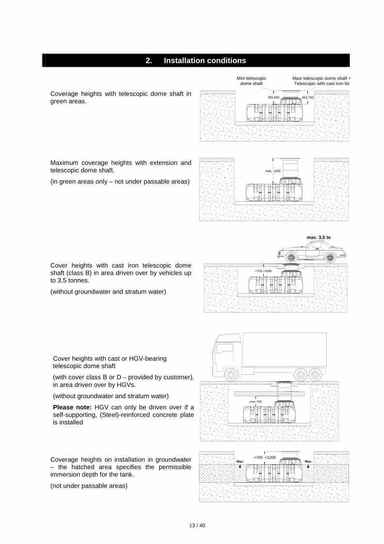
2. Installation conditions
Coverage heights with telescopic dome shaft in green areas.
Maximum coverage heights with extension and telescopic dome shaft.
(in green areas only – not under passable areas)
Cover heights with cast iron telescopic dome shaft (class B) in area driven over by vehicles up to 3.5 tonnes.
(without groundwater and stratum water)
Cover heights with cast or HGV-bearing telescopic dome shaft
(with cover class B or D – provided by customer), in area driven over by HGVs.
(without groundwater and stratum water)
Please note: HGV can only be driven over if a self-supporting, (Steel)-reinforced concrete plate is installed
Coverage heights on installation in groundwater – the hatched area specifies the permissibleimmersion depth for the tank.
(not under passable areas)
Maxi telescopic dome shaft + Telescopic with cast iron lid
Mini telescopic dome shaft
>800 <1200Max.Max.
>700 <1200
>700 <1000
max. 3,5 to
max. 500

14 / 40
185
H
L B
440 (Maxi)
Hges
140
Hges
600340 (Mini) 600
185315 265 185 185
3. Technical data
3.1 Technical Data Platin
(1500 L, 3000 L, 5000 L, 7500 L)
3.2 Technical Data Platin XL
(13000 L)
3.3 Overview tanks Platin, Platin XL
Tank 1500 L 3000 L 5000 L 7500 L 13000 L
Art. No. 390000 390001 390002 390005 390008
Weight 82 kg 180 kg 250 kg 380 kg 680 kg
L 2100 mm 2450 mm 2890 mm 3600 mm 6200 mm
W 1250 mm 2100 mm 2300 mm 2250 mm 2250 mm
H 700 mm 735 mm 950 mm 1250 mm 1250 mm
Htot* 1015 mm 1050 mm 1265 mm 1565 mm 1565 mm
* Htot = total height
Htot Htot
H31
5
H31
5
H g
es.
H g
es.
L
185
265
185
185
B
340
(Min
i)
440
(Max
i)
140
340
(Min
i)34
0 (M
axi)
140
15 / 40
ß
< 300 mm
< 300 mm
< 300 mm
< 300 mm
> 100 mm
ß
--> DIN 4124
6 3
1 4 2 5
> 100 mm
7
1
5
3
4
2
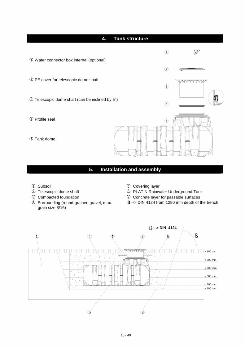
4. Tank structure
� Water connector box internal (optional)
� PE cover for telescopic dome shaft
� Telescopic dome shaft (can be inclined by 5°)
� Profile seal
� Tank dome
5. Installation and assembly
� Subsoil � Telescopic dome shaft� Compacted foundation� Surrounding (round-grained gravel, max.
grain size 8/16)
� Covering layer � PLATIN Rainwater Underground Tank � Concrete layer for passable surfaces ß --> DIN 4124 from 1250 mm depth of the trench

16 / 40
>800 <1200Max.Max.
>700 <1200
5. Installation and assembly
5.1 Construction site
Under all circumstances, the following points must be clarified prior to installation:
• The structural suitability of the ground according to DIN 18196
• Maximum groundwater levels which occur and drainage capability of the subsoil
• Types of load which occur, e.g. traffic loads
• Please note: HGV can only be driven over if a self-supporting, steel-reinforced concrete plate isinstalled!
An expert ground report should be requested from the local planning authority to determine the physical characteristics of the subsoil.
5.2 Trench
To ensure that sufficient space is available for working, the base area of the trench must exceed the dimensions of the tank by > 100 mm on each side; the distance from solid constructions must be at least 1000 mm.
If the depth of the trench is > 1250 mm an embankment must be designed according to DIN 4124. The construction site must be horizontal and plane and must guarantee sufficient load-bearing capacity.
The depth of the trench must be dimensioned so that the max. earth coverage (see point 2 – installation conditions) above the tank is not exceeded. To use the system throughout the entire year, it is necessary to install the tank and those parts of the system which conduct water in the frost-free area. The frost-free depth is usually approx. 600 mm – 800 mm; precise information in this regard can be obtained from the responsible authority.
A layer of compacted, round-grain gravel (grain size 8/ 16, thickness approx. 100 - 150 mm) is applied as the foundation.
5.2.1 Slope, embankment, etc.
On installation of the tank in the immediate vicinity (< 5 m) of a slope, earthen mound or slope, a statically calculated supporting wall must be erected to absorb the soil pressure. The wall must exceed the dimensions of the tank by at least 500 mm in all directions, and must be located at least 1000 mm away from the tank.
5.2.2 Groundwater and cohesive (water-impermeable) soils (e. g. clay soil)
If it is anticipated that the tanks will be immersed deeper into the groundwater than is shown in the adjacent figure, sufficient dissipation must be ensured. (See table for max. immersion depth).
Dissipation of the drainage water (e. g. via an annular drainage system) is recommended in the case of cohesive, water-impermeable soils.
Tank 1500 L 3000 L 5000 L 7500 L 13000 L
max. immersion depth 700 mm 735 mm 950 mm 1250 mm 1250 mm
[email protected] www.graf.info
17 / 40
H
>H
5. Installation and assembly
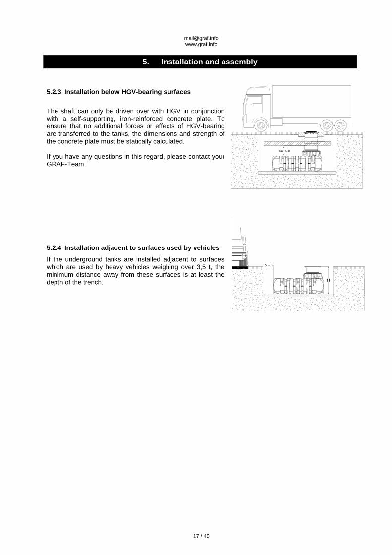
5.2.3 Installation below HGV-bearing surfaces
The shaft can only be driven over with HGV in conjunction with a self-supporting, iron-reinforced concrete plate. To ensure that no additional forces or effects of HGV-bearing are transferred to the tanks, the dimensions and strength of the concrete plate must be statically calculated.
If you have any questions in this regard, please contact your GRAF-Team.
5.2.4 Installation adjacent to surfaces used by vehicles
If the underground tanks are installed adjacent to surfaces which are used by heavy vehicles weighing over 3,5 t, the minimum distance away from these surfaces is at least the depth of the trench.
max. 500
18 / 40
>500
5. Installation and assembly
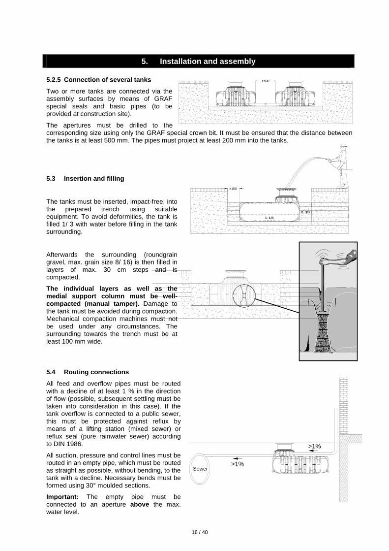
5.2.5 Connection of several tanks
Two or more tanks are connected via the assembly surfaces by means of GRAF special seals and basic pipes (to be provided at construction site).
The apertures must be drilled to the corresponding size using only the GRAF special crown bit. It must be ensured that the distance between the tanks is at least 500 mm. The pipes must project at least 200 mm into the tanks.
5.3 Insertion and filling
The tanks must be inserted, impact-free, into the prepared trench using suitable equipment. To avoid deformities, the tank is filled 1/ 3 with water before filling in the tank surrounding.
Afterwards the surrounding (roundgrain gravel, max. grain size 8/ 16) is then filled in layers of max. 30 cm steps and is compacted.
The individual layers as well as the medial support column must be well-compacted (manual tamper). Damage to the tank must be avoided during compaction. Mechanical compaction machines must not be used under any circumstances. The surrounding towards the trench must be at least 100 mm wide.
5.4 Routing connections
All feed and overflow pipes must be routed with a decline of at least 1 % in the direction of flow (possible, subsequent settling must be taken into consideration in this case). If the tank overflow is connected to a public sewer, this must be protected against reflux by means of a lifting station (mixed sewer) or reflux seal (pure rainwater sewer) according to DIN 1986.
All suction, pressure and control lines must be routed in an empty pipe, which must be routed as straight as possible, without bending, to the tank with a decline. Necessary bends must be formed using 30° moulded sections.
Important: The empty pipe must be connected to an aperture above the max. water level.
Kanal
>1%
>1%Sewer
2. 3/3
>100
1. 1/3
19 / 40
1
3
2
2
4
1
3
1
2
3
4
5
6
6. Assembling the and telescopic dome shaft
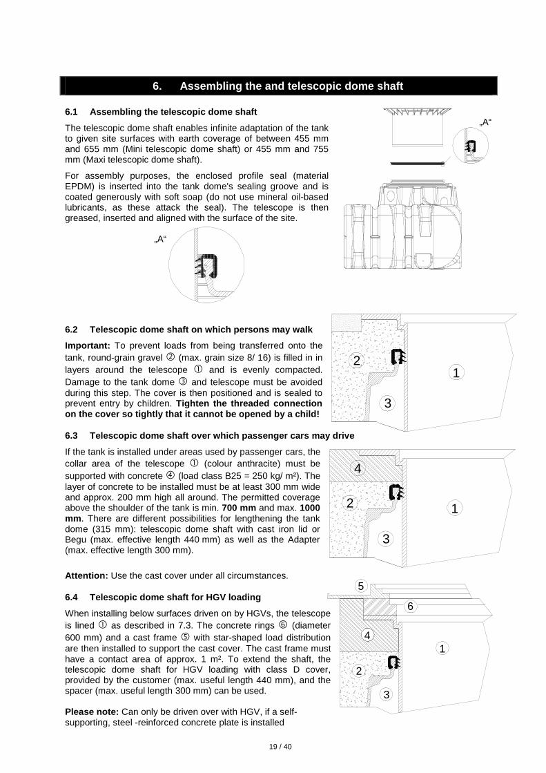
6.1 Assembling the telescopic dome shaft
The telescopic dome shaft enables infinite adaptation of the tank to given site surfaces with earth coverage of between 455 mm and 655 mm (Mini telescopic dome shaft) or 455 mm and 755 mm (Maxi telescopic dome shaft).
For assembly purposes, the enclosed profile seal (material EPDM) is inserted into the tank dome's sealing groove and is coated generously with soft soap (do not use mineral oil-based lubricants, as these attack the seal). The telescope is then greased, inserted and aligned with the surface of the site.
6.2 Telescopic dome shaft on which persons may walk
Important: To prevent loads from being transferred onto the tank, round-grain gravel � (max. grain size 8/ 16) is filled in in layers around the telescope � and is evenly compacted. Damage to the tank dome � and telescope must be avoided during this step. The cover is then positioned and is sealed to prevent entry by children. Tighten the threaded connection on the cover so tightly that it cannot be opened by a child!
6.3 Telescopic dome shaft over which passenger cars may drive
If the tank is installed under areas used by passenger cars, the collar area of the telescope � (colour anthracite) must be supported with concrete � (load class B25 = 250 kg/ m²). The layer of concrete to be installed must be at least 300 mm wide and approx. 200 mm high all around. The permitted coverage above the shoulder of the tank is min. 700 mm and max. 1000 mm . There are different possibilities for lengthening the tankdome (315 mm): telescopic dome shaft with cast iron lid orBegu (max. effective length 440 mm) as well as the Adapter(max. effective length 300 mm).
Attention: Use the cast cover under all circumstances.
6.4 Telescopic dome shaft for HGV loading
When installing below surfaces driven on by HGVs, the telescope is lined � as described in 7.3. The concrete rings � (diameter 600 mm) and a cast frame � with star-shaped load distribution are then installed to support the cast cover. The cast frame must have a contact area of approx. 1 m². To extend the shaft, the telescopic dome shaft for HGV loading with class D cover, provided by the customer (max. useful length 440 mm), and the spacer (max. useful length 300 mm) can be used.
Please note: Can only be driven over with HGV, if a self-supporting, steel -reinforced concrete plate is installed
„A“
„A“
20 / 40
7. Assembly of the adapter
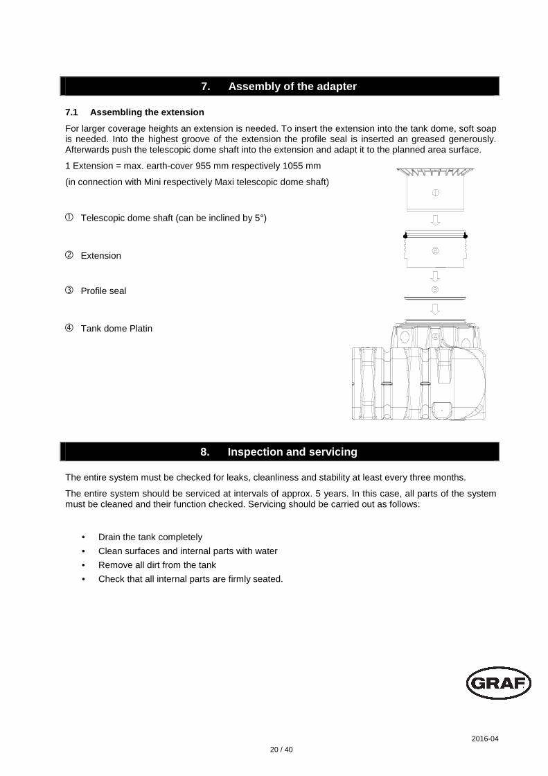
7.1 Assembling the extension
For larger coverage heights an extension is needed. To insert the extension into the tank dome, soft soap is needed. Into the highest groove of the extension the profile seal is inserted an greased generously. Afterwards push the telescopic dome shaft into the extension and adapt it to the planned area surface.
1 Extension = max. earth-cover 955 mm respectively 1055 mm
(in connection with Mini respectively Maxi telescopic dome shaft)
8. Inspection and servicing
The entire system must be checked for leaks, cleanliness and stability at least every three months.
The entire system should be serviced at intervals of approx. 5 years. In this case, all parts of the system must be cleaned and their function checked. Servicing should be carried out as follows:
• Drain the tank completely
• Clean surfaces and internal parts with water
• Remove all dirt from the tank
• Check that all internal parts are firmly seated.
� Telescopic dome shaft (can be inclined by 5°)
� Extension
� Profile seal
� Tank dome Platin
2016-04