Embed Size (px)
Citation preview
ATLANTA
Model No. FBFR**MN
** denotes fascia variant
RADIANT BALANCED FLUE GAS FIRE
Installation and Maintenance Instructions Hand these instructions to the user This appliance is only for use on Natural Gas (G20) at a supply pressure of 20 mbar in GB / I.E. Before Installation, ensure that the local distribution conditions and the adjustment of the appliance are compatible.
2
CONTENTS
Section 1 Information and Requirements PAGE 1.0 Appliance Information 3 1.1 Conditions of Installation 4 1.2 Fireplace / surround suitability 4 1.3 Flue terminal position 5 1.4 Shelf position 6 1.5 Hearths 6 Section 2 Installation of Fire
2.1 Unpacking the fire 7 2.2 Fire place opening / catchment 7
2.3 Preparation of the wall 9 2.4 Flue installation 10-11 2.5 Gas pipe installation 12 2.6 Securing the firebox to the wall 13-16 2.7 Removing the glass frame 17
2.8 Fitting the flue terminal 18 2.9 Fitting the optional terminal guard 19 2.10 Gas tightness and burner pressure 19-20 2.11 Lighting the appliance 20 Section 3 Maintenance 3.1 Removal of the Piezo Igniter 21 3.2 Removal of the Control valve 21
3.3 Removal of the Pilot Assembly 22 3.4 Removal of the burner 22
Model number FBFR**MN, ** denotes trim / fret variant Manufactured by: - BFM Europe Ltd Trentham Lakes Stoke-on-Trent Staffordshire ST4 4TJ Telephone 01782 339000 Efficiency Declaration The efficiency of this appliance has been measured as specified in BS EN 613 : 2001 and the result is 75%. The gross calorific value of the fuel has been used for this efficiency calculation. The test data from which it has been calculated has been certified by Advantica. The efficiency value may be used in the UK Government’s Standard Assessment Procedure (SAP) for energy rating of dwellings.
3
SECTION 1 INFORMATION AND REQUIREMENTS
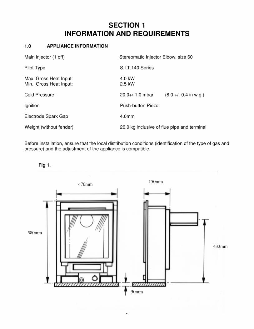
1.0 APPLIANCE INFORMATION Main injector (1 off) Stereomatic Injector Elbow, size 60 Pilot Type S.I.T.140 Series Max. Gross Heat Input: 4.0 kW Min. Gross Heat Input: 2.5 kW Cold Pressure: 20.0+/-1.0 mbar (8.0 +/- 0.4 in w.g.) Ignition Push-button Piezo Electrode Spark Gap 4.0mm Weight (without fender) 26.0 kg inclusive of flue pipe and terminal
Before installation, ensure that the local distribution conditions (identification of the type of gas and pressure) and the adjustment of the appliance is compatible.
Fig 1.
1.1 CONDITIONS OF INSTALLATION
470mm 150mm
433mm
580mm
50mm

4
1.1 INSTALLATION CONDITIONS It is the law that all gas appliances are installed only by a GAS SAFE Registered Installer, in accordance with these installation instructions and the Gas Safety (Installation and Use) Regulations 1998 as amended. Failure to install appliances correctly could lead to prosecution. It is in your own interest and that of safety to comply with the law. The installation must also be in accordance with all relevant parts of the Local and National Building Regulations where appropriate, the Building Regulations (Scotland Consolidation) issued by the Scottish Development Department, and all applicable requirements of the following British Standard Code of Practice. 1. B.S. 5871 Part 1 Installation of Gas Fires 2. B.S. 6891 Installation of Gas Pipework 3. B.S. 5440 Parts 1 & 2 Installation of Flues and Ventilation 1.2 FIREPLACE / SURROUND SUITABILITY The fire is suitable for fitting to non-combustible fireplace surrounds and proprietary fireplace surrounds with a temperature rating of at least 150
oc.
If a heating appliance is fitted directly against a wall without the use of a fire surround or fireplace all combustible material must be removed from behind the trim. Soft wall coverings such as blown vinyl, wallpaper etc. could be affected by the rising hot air and scorching and/or discoloration may result. Due consideration should be made to this when installing or decorating.
5
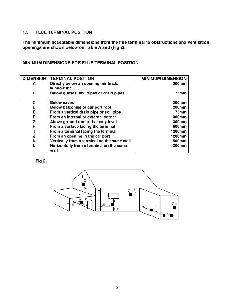
1.3 FLUE TERMINAL POSITION The minimum acceptable dimensions from the flue terminal to obstructions and ventilation openings are shown below on Table A and (Fig 2).
MINIMUM DIMENSIONS FOR FLUE TERMINAL POSITION
DIMENSI0N TERMINAL POSITION MINIMUM DIMENSION A Directly below an opening, air brick,
window etc 300mm
B Below gutters, soil pipes or drain pipes 75mm
C Below eaves 200mm
D Below balconies or car port roof 200mm
E From a vertical drain pipe or soil pipe 75mm
F From an internal or external corner 300mm
G Above ground roof or balcony level 300mm
H From a surface facing the terminal 600mm
I From a terminal facing the terminal 1200mm
J From an opening in the car port 1200mm
K Vertically from a terminal on the same wall 1500mm
L Horizontally from a terminal on the same wall
300mm
Fig 2.
B
C
F
F
L
K
G H
D
J
G
A
A
E
6
1.4 SHELF POSITION The fire may be fitted below a combustible shelf providing there is a minimum distance of 200mm above the top of the fire and the shelf does not project more than 150mm. If the shelf overhangs more than 150mm the distance between the fire and the shelf must be increased by 15mm for every 25mm of additional overhang over 150mm. 1.5 HEARTHS This appliance does not require the fitting of a hearth, but we do recommend that a hearth of minimum width 760mm and minimum projection forwards of 125mm is used. This recommended hearth can be manufactured from combustible or non-combustible material.
7
SECTION 2 INSTALLATION OF FIRE
2.1 UNPACKING THE FIRE Carefully lift the fire out of the carton. Remove the loose item packaging carefully from the front of the appliance.
IMPORTANT: THE CARDBOARD FITMENT THAT IS AT THE TOP OF THE
CONVECTION APERTURE SHOULD NOT BE REMOVED UNTIL THE APPLIANCE IS FULLY INSTALLED AND READY TO BE LIT.
DO NOT UNDER ANY CIRCUMSTANCES USE THIS APPLIANCE IF THE GLASS PANEL IS BROKEN OR NOT SECURELY FIXED TO THE FIREBOX.
Check the contents as listed: - Packing Check List 1off Fire box / burner assembly 1off Fascia Assembly & Ashpan Cover 1off Flue Terminal unit – pack 2 of 2 1off Loose Items pack – containing :- 1 off Flue pipe gasket 4 off No.12 x 65mm fixing screws 15 off No.8 x 10mm fixing screws 4 off rawplugs 1 off 6mm Allen Key 1off Right Hand Supply Pipe
1off cable fixing kit 1 off heat deflector plate
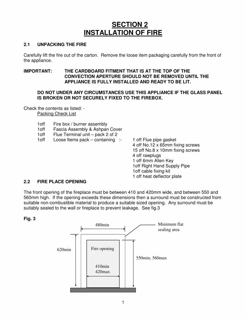
2.2 FIRE PLACE OPENING The front opening of the fireplace must be between 410 and 420mm wide, and between 550 and 560mm high. If the opening exceeds these dimensions then a surround must be constructed from suitable non-combustible material to produce a suitable sized opening. Any surround must be suitably sealed to the wall or fireplace to prevent leakage. See fig.3
Fig. 3
550min, 560max
410min
420max
480min Minimum flat
sealing area
620min Fire opening
8
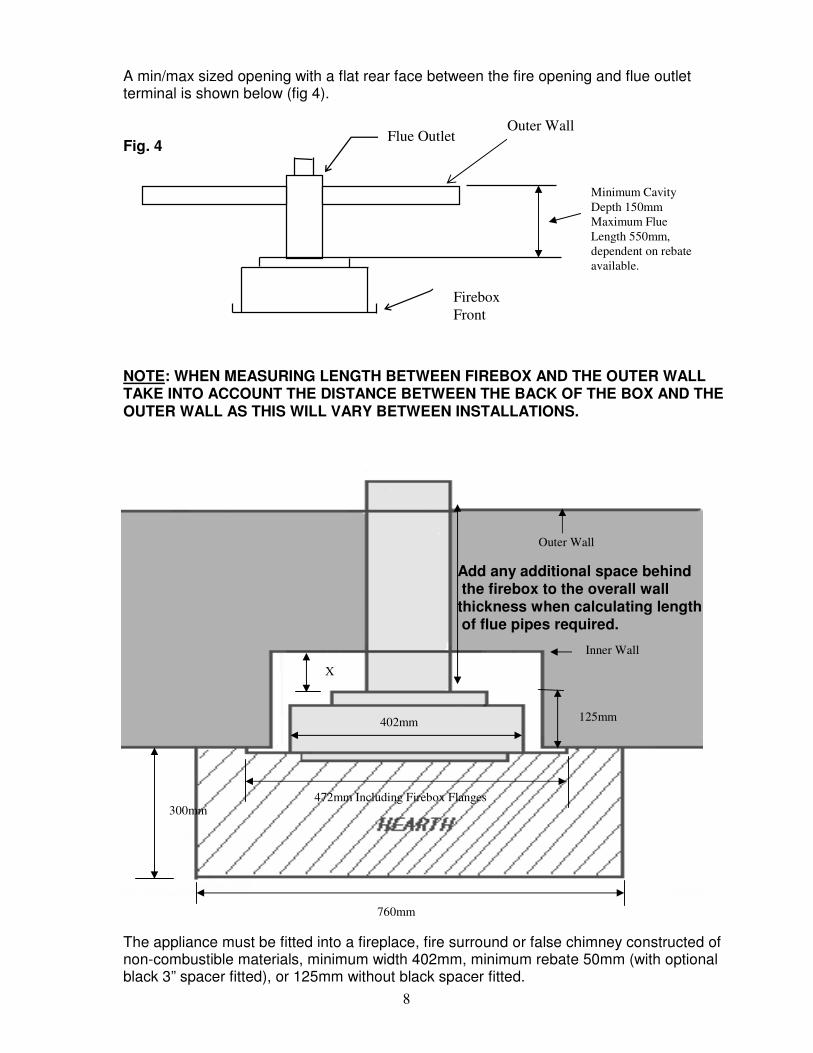
A min/max sized opening with a flat rear face between the fire opening and flue outlet terminal is shown below (fig 4). Fig. 4
NOTE: WHEN MEASURING LENGTH BETWEEN FIREBOX AND THE OUTER WALL TAKE INTO ACCOUNT THE DISTANCE BETWEEN THE BACK OF THE BOX AND THE OUTER WALL AS THIS WILL VARY BETWEEN INSTALLATIONS. The appliance must be fitted into a fireplace, fire surround or false chimney constructed of non-combustible materials, minimum width 402mm, minimum rebate 50mm (with optional black 3” spacer fitted), or 125mm without black spacer fitted.
X
300mm
125mm
Add any additional space behind the firebox to the overall wall thickness when calculating length of flue pipes required.
760mm
Inner Wall
Outer Wall
402mm
472mm Including Firebox Flanges
Firebox
Front
Flue Outlet
Minimum Cavity
Depth 150mm
Maximum Flue
Length 550mm,
dependent on rebate
available.
Outer Wall
9
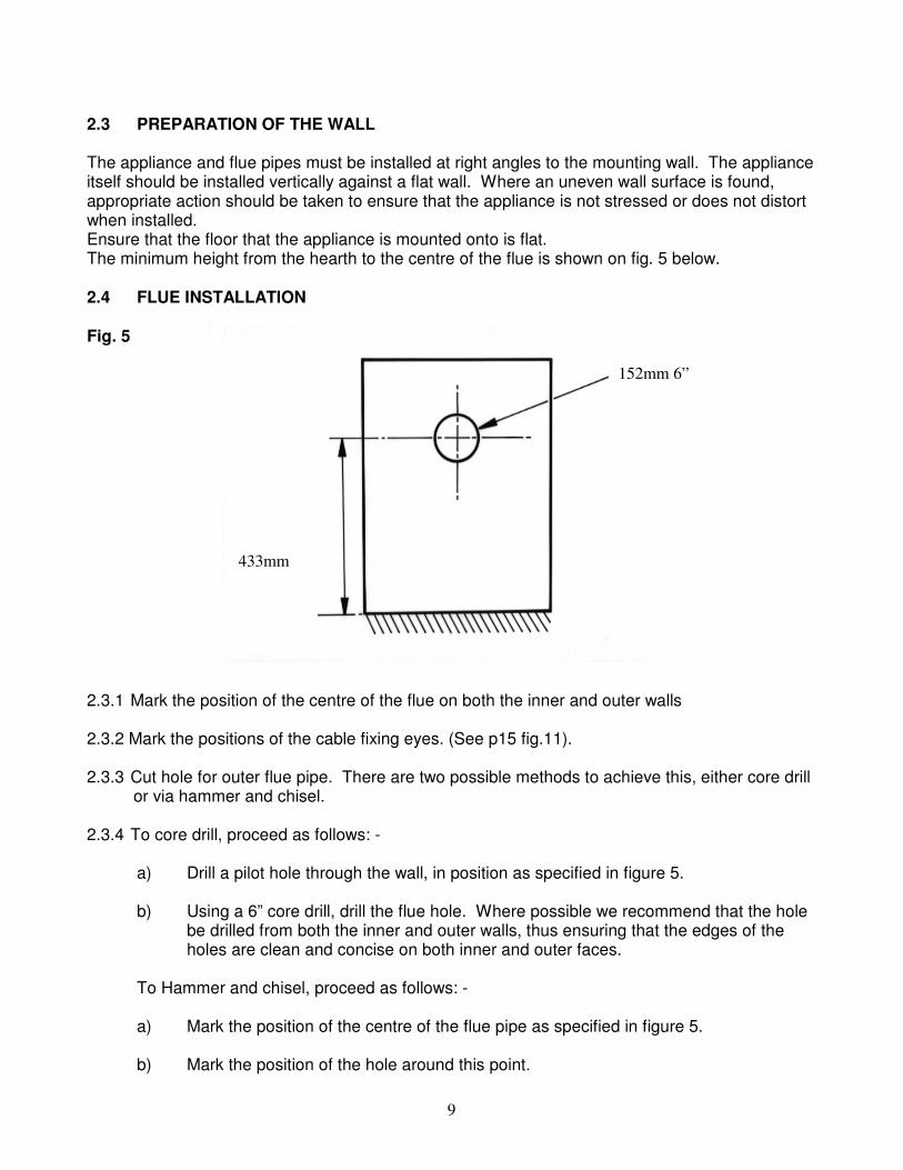
2.3 PREPARATION OF THE WALL The appliance and flue pipes must be installed at right angles to the mounting wall. The appliance itself should be installed vertically against a flat wall. Where an uneven wall surface is found, appropriate action should be taken to ensure that the appliance is not stressed or does not distort when installed. Ensure that the floor that the appliance is mounted onto is flat. The minimum height from the hearth to the centre of the flue is shown on fig. 5 below.
2.4 FLUE INSTALLATION Fig. 5
2.3.1 Mark the position of the centre of the flue on both the inner and outer walls 2.3.2 Mark the positions of the cable fixing eyes. (See p15 fig.11). 2.3.3 Cut hole for outer flue pipe. There are two possible methods to achieve this, either core drill or via hammer and chisel.
2.3.4 To core drill, proceed as follows: -
a) Drill a pilot hole through the wall, in position as specified in figure 5. b) Using a 6” core drill, drill the flue hole. Where possible we recommend that the hole
be drilled from both the inner and outer walls, thus ensuring that the edges of the holes are clean and concise on both inner and outer faces.
To Hammer and chisel, proceed as follows: - a) Mark the position of the centre of the flue pipe as specified in figure 5. b) Mark the position of the hole around this point.
152mm 6”
433mm
10
c) Chisel out the area as marked on the wall. d) We then recommend that a cardboard cylinder is placed around the flue pipe and
inserted in the chiselled out hole whilst making good. NOTE: - If the appliance is to be installed into a building under construction, it is
recommended that a non-corrosive metal tube of 6” diameter be inserted into the position of the hole as specified on figure 5 of the previous page.
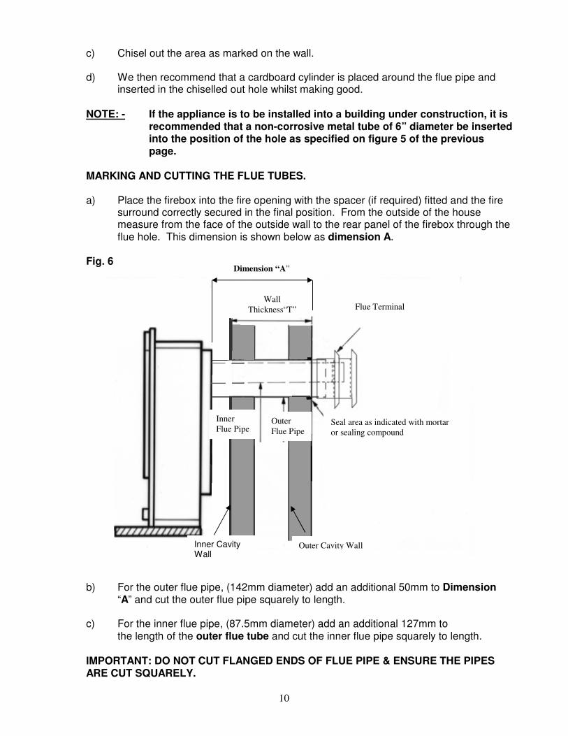
MARKING AND CUTTING THE FLUE TUBES. a) Place the firebox into the fire opening with the spacer (if required) fitted and the fire
surround correctly secured in the final position. From the outside of the house measure from the face of the outside wall to the rear panel of the firebox through the flue hole. This dimension is shown below as dimension A.
Fig. 6 b) For the outer flue pipe, (142mm diameter) add an additional 50mm to Dimension
“A” and cut the outer flue pipe squarely to length. c) For the inner flue pipe, (87.5mm diameter) add an additional 127mm to the length of the outer flue tube and cut the inner flue pipe squarely to length. IMPORTANT: DO NOT CUT FLANGED ENDS OF FLUE PIPE & ENSURE THE PIPES ARE CUT SQUARELY.
Flue Terminal
Seal area as indicated with mortar
or sealing compound
Inner Cavity Wall
Outer Cavity Wall
Dimension “A”
Wall
Thickness“T”
Inner
Flue Pipe Outer
Flue Pipe
11
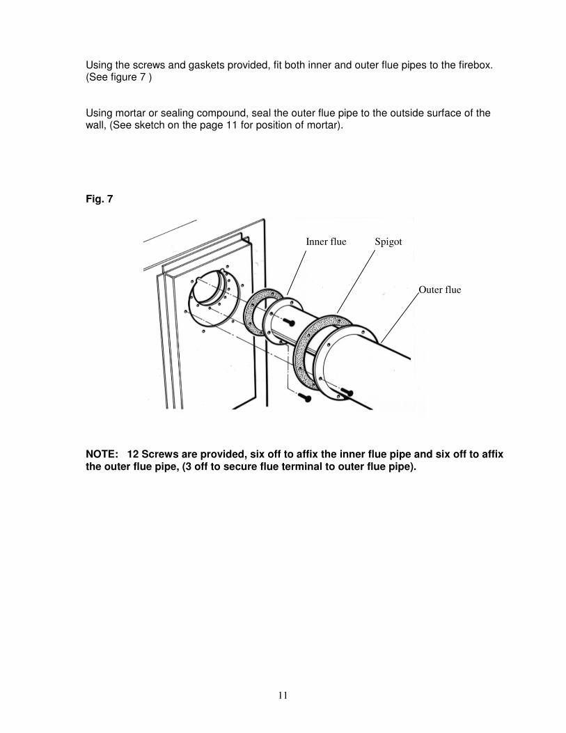
Using the screws and gaskets provided, fit both inner and outer flue pipes to the firebox. (See figure 7 ) Using mortar or sealing compound, seal the outer flue pipe to the outside surface of the wall, (See sketch on the page 11 for position of mortar). Fig. 7
NOTE: 12 Screws are provided, six off to affix the inner flue pipe and six off to affix the outer flue pipe, (3 off to secure flue terminal to outer flue pipe).
Spigot
Outer flue
Inner flue
12
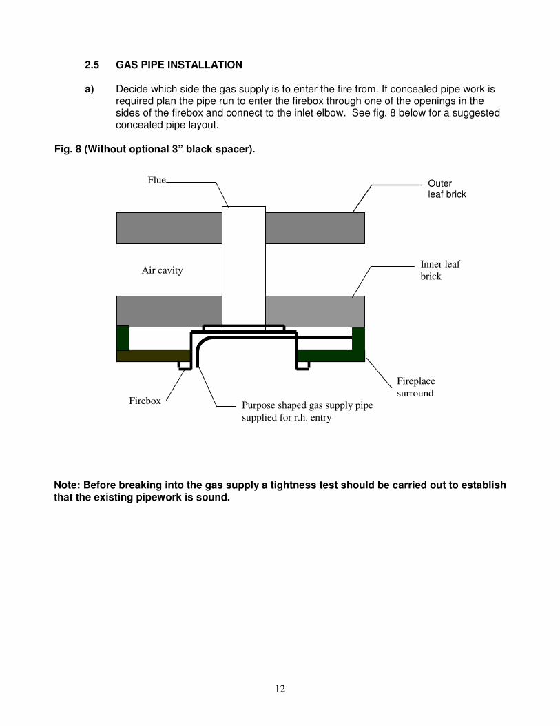
2.5 GAS PIPE INSTALLATION a) Decide which side the gas supply is to enter the fire from. If concealed pipe work is
required plan the pipe run to enter the firebox through one of the openings in the sides of the firebox and connect to the inlet elbow. See fig. 8 below for a suggested concealed pipe layout.
Fig. 8 (Without optional 3” black spacer).
Note: Before breaking into the gas supply a tightness test should be carried out to establish that the existing pipework is sound.
Purpose shaped gas supply pipe
supplied for r.h. entry
Fireplace
surround
Outer leaf brick
Air cavity Inner leaf
brick
Flue
Firebox
13
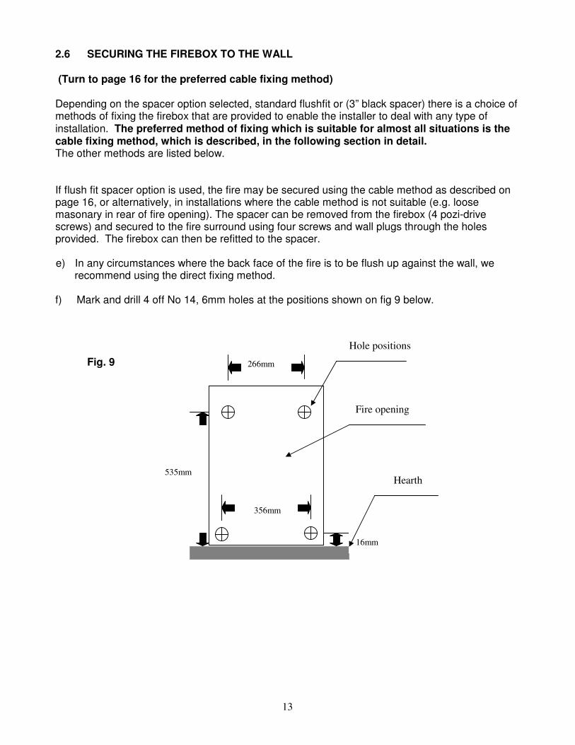
2.6 SECURING THE FIREBOX TO THE WALL (Turn to page 16 for the preferred cable fixing method) Depending on the spacer option selected, standard flushfit or (3” black spacer) there is a choice of methods of fixing the firebox that are provided to enable the installer to deal with any type of installation. The preferred method of fixing which is suitable for almost all situations is the cable fixing method, which is described, in the following section in detail. The other methods are listed below. If flush fit spacer option is used, the fire may be secured using the cable method as described on page 16, or alternatively, in installations where the cable method is not suitable (e.g. loose masonary in rear of fire opening). The spacer can be removed from the firebox (4 pozi-drive screws) and secured to the fire surround using four screws and wall plugs through the holes provided. The firebox can then be refitted to the spacer. e) In any circumstances where the back face of the fire is to be flush up against the wall, we
recommend using the direct fixing method. f) Mark and drill 4 off No 14, 6mm holes at the positions shown on fig 9 below.
Fig. 9
Fire opening
535mm
266mm
16mm
356mm
Hearth
Hole positions
14
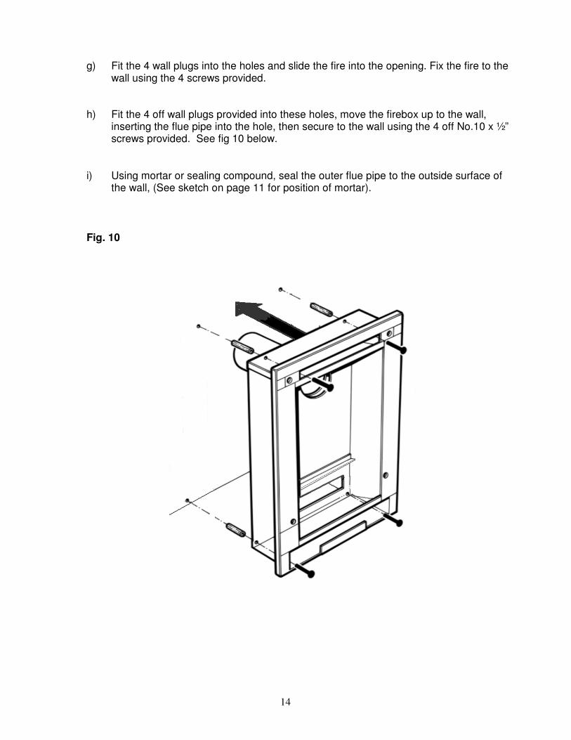
g) Fit the 4 wall plugs into the holes and slide the fire into the opening. Fix the fire to the
wall using the 4 screws provided.
h) Fit the 4 off wall plugs provided into these holes, move the firebox up to the wall, inserting the flue pipe into the hole, then secure to the wall using the 4 off No.10 x ½” screws provided. See fig 10 below.
i) Using mortar or sealing compound, seal the outer flue pipe to the outside surface of the wall, (See sketch on page 11 for position of mortar).
Fig. 10
15
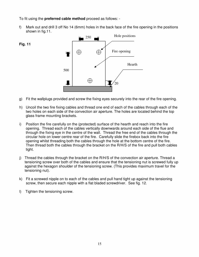
To fit using the preferred cable method proceed as follows: - f) Mark out and drill 3 off No 14 (6mm) holes in the back face of the fire opening in the positions shown in fig.11.
Fig. 11 g) Fit the wallplugs provided and screw the fixing eyes securely into the rear of the fire opening.
h) Uncoil the two fire fixing cables and thread one end of each of the cables through each of the
two holes on each side of the convection air aperture. The holes are located behind the top glass frame mounting brackets.
i) Position the fire carefully on the (protected) surface of the hearth and reach into the fire
opening. Thread each of the cables vertically downwards around each side of the flue and through the fixing eye in the centre of the wall. Thread the free end of the cables through the circular hole on lower centre rear of the fire. Carefully slide the firebox back into the fire opening whilst threading both the cables through the hole at the bottom centre of the fire. Then thread both the cables through the bracket on the R/H/S of the fire and pull both cables tight.
j) Thread the cables through the bracket on the R/H/S of the convection air aperture. Thread a
tensioning screw over both of the cables and ensure that the tensioning nut is screwed fully up against the hexagon shoulder of the tensioning screw. (This provides maximum travel for the tensioning nut).
k) Fit a screwed nipple on to each of the cables and pull hand tight up against the tensioning
screw, then secure each nipple with a flat bladed screwdriver. See fig. 12. l) Tighten the tensioning screw.
500
20
250
Fire opening
Hearth
Hole positions
16
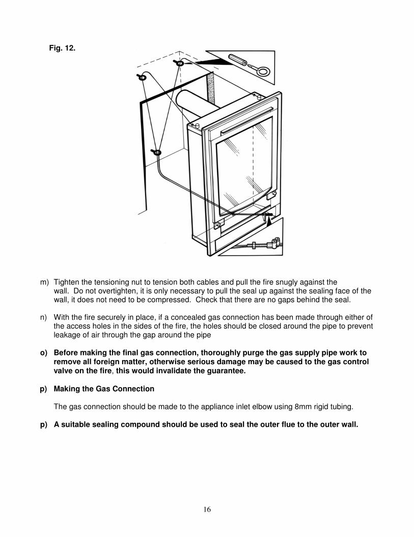
Fig. 12.
m) Tighten the tensioning nut to tension both cables and pull the fire snugly against the
wall. Do not overtighten, it is only necessary to pull the seal up against the sealing face of the wall, it does not need to be compressed. Check that there are no gaps behind the seal.
n) With the fire securely in place, if a concealed gas connection has been made through either of
the access holes in the sides of the fire, the holes should be closed around the pipe to prevent leakage of air through the gap around the pipe
o) Before making the final gas connection, thoroughly purge the gas supply pipe work to remove all foreign matter, otherwise serious damage may be caused to the gas control valve on the fire, this would invalidate the guarantee. p) Making the Gas Connection
The gas connection should be made to the appliance inlet elbow using 8mm rigid tubing.
p) A suitable sealing compound should be used to seal the outer flue to the outer wall.
17
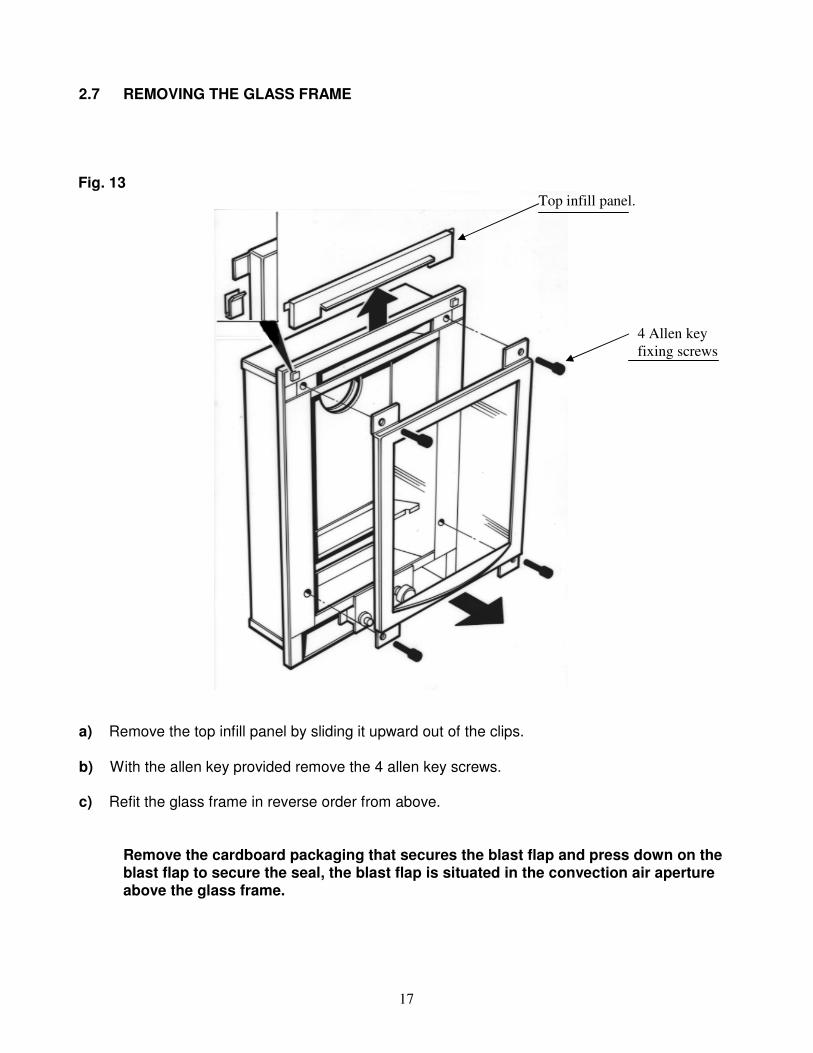
2.7 REMOVING THE GLASS FRAME
Fig. 13
a) Remove the top infill panel by sliding it upward out of the clips. b) With the allen key provided remove the 4 allen key screws.
c) Refit the glass frame in reverse order from above.
Remove the cardboard packaging that secures the blast flap and press down on the blast flap to secure the seal, the blast flap is situated in the convection air aperture above the glass frame.
4 Allen key
fixing screws
Top infill panel.
18
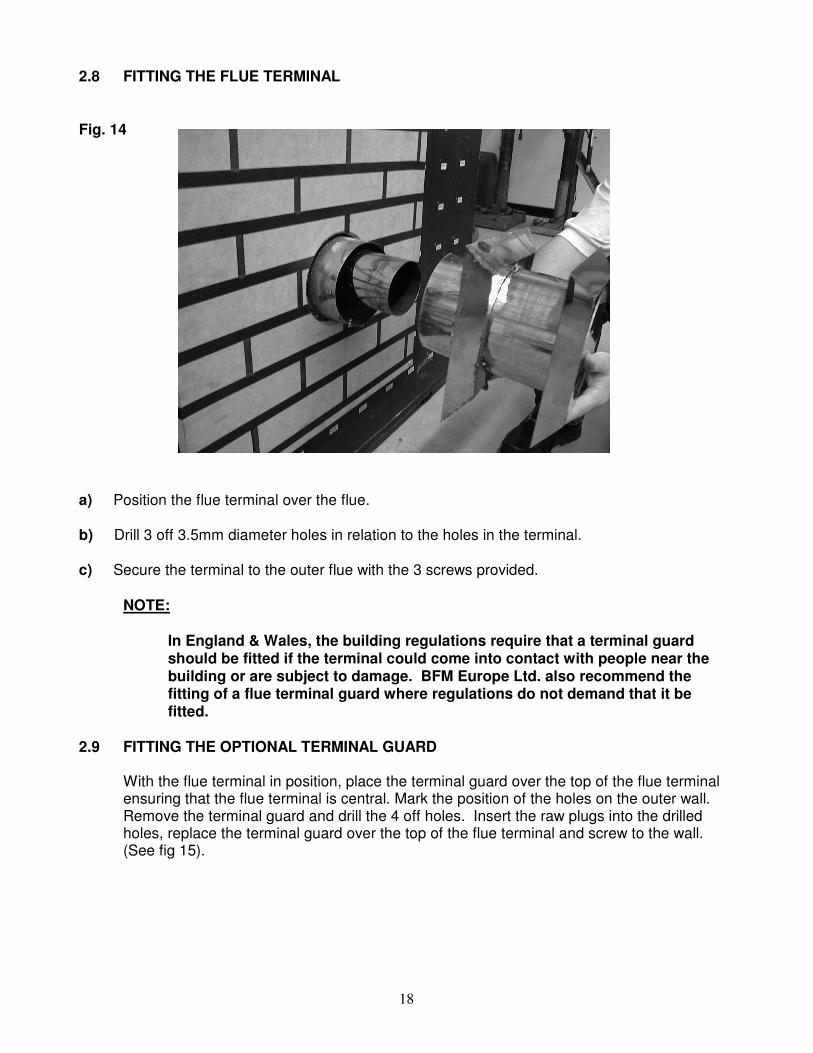
2.8 FITTING THE FLUE TERMINAL
Fig. 14
a) Position the flue terminal over the flue.
b) Drill 3 off 3.5mm diameter holes in relation to the holes in the terminal. c) Secure the terminal to the outer flue with the 3 screws provided.
NOTE:
In England & Wales, the building regulations require that a terminal guard
should be fitted if the terminal could come into contact with people near the building or are subject to damage. BFM Europe Ltd. also recommend the fitting of a flue terminal guard where regulations do not demand that it be fitted.
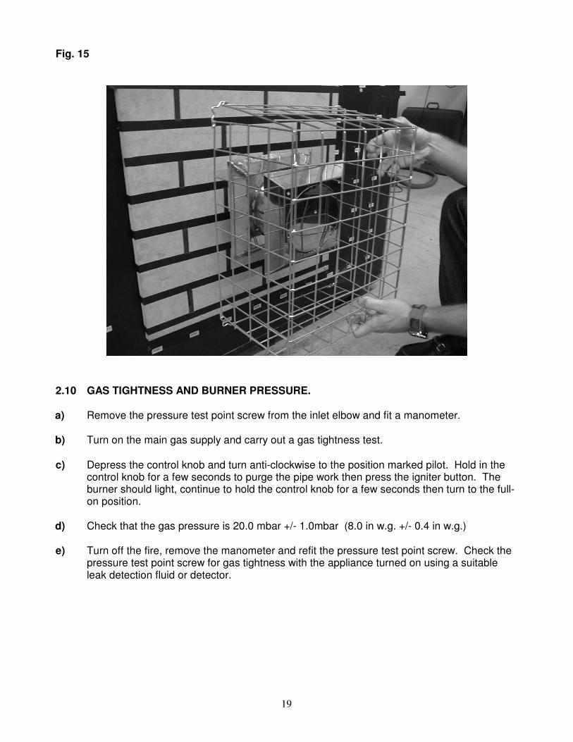
2.9 FITTING THE OPTIONAL TERMINAL GUARD
With the flue terminal in position, place the terminal guard over the top of the flue terminal ensuring that the flue terminal is central. Mark the position of the holes on the outer wall. Remove the terminal guard and drill the 4 off holes. Insert the raw plugs into the drilled holes, replace the terminal guard over the top of the flue terminal and screw to the wall. (See fig 15).
19
Fig. 15
2.10 GAS TIGHTNESS AND BURNER PRESSURE. a) Remove the pressure test point screw from the inlet elbow and fit a manometer. b) Turn on the main gas supply and carry out a gas tightness test. c) Depress the control knob and turn anti-clockwise to the position marked pilot. Hold in the
control knob for a few seconds to purge the pipe work then press the igniter button. The burner should light, continue to hold the control knob for a few seconds then turn to the full-on position.
d) Check that the gas pressure is 20.0 mbar +/- 1.0mbar (8.0 in w.g. +/- 0.4 in w.g.)
e) Turn off the fire, remove the manometer and refit the pressure test point screw. Check the
pressure test point screw for gas tightness with the appliance turned on using a suitable leak detection fluid or detector.
20
2.11 LIGHTING THE APPLIANCE a) Turn on the gas restrictor at the inlet fitting. b) Depress the control knob and turn anti-clockwise to the position marked pilot. Hold in the
control knob for a few seconds to purge the pipe work. c) Continue to hold-in the control knob and press the igniter button. If the burner does not
light, continue to press the igniter button until ignition occurs. Continue to hold the control knob for 5-10 seconds to allow thermocouple to heat up, if the pilot goes out when the control knob is released, repeat the lighting sequence.
d) Turn the control knob in the anti-clockwise direction to the high position and the main burner
will light.
e) Turn the control knob clockwise to the low position and the gas input will be reduced to the minimum setting.
f) Slightly depress the control knob and turn to the pilot position, the main burner will go out
but the pilot will remain lit. g) Slightly depress the control knob and turn to the off position, the pilot is now extinguished.
h) Finally fit the fascia
Finally, hand the Installation and Maintenance Instructions and the Users Instructions over to the customer and explain the operation of the fire
WHEN TURNING THE FIRE “OFF” PLEASE ENSURE THAT THE CONTROLVALVE IS TURNED TO THE “OFF” POSITION AND THE PILOT FLAME IS EXTINGUISHED. DO NOT LEAVE THE PILOT FLAME ONLY LIT.
NOTE: THIS APPLIANCE IS DESIGNED TO WORK SAFELY AND EFFECTIVELY DURING ADVERSE WEATHER CONDITIONS. HOWEVER, DURING SUCH TIMES, FLAME DISTURBANCE MAY BE NOTICED. THIS IS NORMAL AND DOES NOT EFFECT OR IMPAIRE THE SAFETY OF THE APPLIANCE.
21
SECTION 3 MAINTENANCE
Servicing Notes
• Servicing should be carried out annually by a competent person such as a GAS SAFE registered engineer. It is a condition of Flavel guarantees that this is carried out by a competent person a GAS SAFE registered Engineer in accordance with these servicing notes
• For continued safe operation of the fire the pilot assembly must be replaced at the annual service. Pilot renewal is also a condition of the above guarantee schemes.
• The condition of the Fibre ribbed back should be checked and if necessary should be replaced with a genuine replacement only available from BFM Europe Ltd.
3.1 Removing the Piezo Igniter.
a) Remove fascia from the front of the fire. Isolate the gas supply, loosen the inlet nut, and remove the 2 screws that secure the pilot heat shield, remove the shield.
b) Loosen the nut to the bulkhead fitting, which is located to the left-hand side of the convection air aperture. c) Loosen the pilot pipe, disconnect the ignition lead from the electrode and disconnect the thermocouple from the pilot assembly. d) Remove the 4 off fixing screws that secure the control panel in place. e) Slide the control panel and gas train forwards. f) Disconnect the ignition lead from the piezo and unscrew the retaining nut on the rear of the control panel. Withdraw the piezo from the front of the control panel. Reassemble in reverse order and carry out a gas tightness test.
3.2 Removing the Control Valve from the fire.
a) Remove the fascia from the front of the fire to a safe location. b) Isolate the gas supply. Loosen the inlet nut, remove the 2 screws that secure the pilot heat shield, remove the shield. c) Unscrew the pilot heat shield and remove from the fire. d) Loosen the nut to the bulkhead fitting, which is located to the L/H/S of the convection air aperture.
e) Unscrew the 4 screws that secure the control panel in place. f) Loosen and remove the pilot pipe, ignition lead and thermocouple from the pilot body.
g) Pull the control panel away from the fire. h) Pull the control knob from the valve and remove the control valve-locking nut. i) Unscrew the inlet nut, pilot nut, main pipe and release the thermocouple nut from the end of the control valve. We do not recommend re-greasing or servicing of control valves. Defective valves should be replaced with a genuine replacement of the correct type.
j) To refit a control tap, reassemble in reverse order noting that the control tap locates with a flat in the control panel. Carry out a gas tightness test after reassembly.
22
3.3 Removing the Pilot Assembly.
a) Remove the fascia from the front of the fire to a safe location. b) Unscrew the pilot heat shield.
c) Loosen the pilot pipe and thermocouple then disconnect the ignition lead from the pilot body. d) Unscrew the 2 screws that secure the pilot body to the fire. e) Remove the pilot assembly. f) Re-assemble with a new pilot and gasket, ensuring that an even seal around the pilot assembly is obtained.
3.4 Removing the burner from the fire.
a) Remove the fascia from the front of the fire to a safe location. b) Remove the glass frame as described in section 3.2. c) Isolate the gas supply. d) Unscrew the 2 screws that secure the pilot heat shield in place. e) Unscrew the 2 screws that secure the pilot assembly to the pilot-fixing panel. f) Remove 11 off fixing screws that hold the pilot-mounting panel in place. g) Slide the pilot panel upwards and away from the pilot assembly. h) Loosen the main burner pipe that is situated to L/H/S below the burner on the
bulkhead fitting. i) Remove the 2 off fixing screws that secure the burner in place. j) Remove the burner from the fire. k) Re-assemble in reverse order.
WARNING If the glass on the appliance is damaged, removed or fitted incorrectly the fire must not be used.

23
Due to our policy of continual improvement and development the exact accuracy of illustrations and descriptions contained in this book cannot be guarantee.
Part B-104480
Issue 2
BFM Europe Ltd.
Trentham Lakes
Stoke-on-Trent
Staffordshire
ST4 4TJ
www.bfm-europe.com
Telephone 01782 339000
Telephone (Service) 0844 7700169