Embed Size (px)
Citation preview

Installation and Maintenance Manual
Sliding Gate Operators
Inbuilt Models: GDS 450, 630 LI PROMade in Australia from Australian & quality imported components
Installation and Maintenance Manual
Sliding Gate OperatorsInbuilt Models: GDS 450, 630 LI PRO Range
Made in Australia from Australian & quality imported components
A.B.N. 62 059 806 405
Nov 2014
N14870
Installation and Maintenance Manual
Sliding Gate Operators Range
Made in Australia from Australian & quality imported components

Abbreviated Installa
Sl id ing Gate Operators
PLEASE NOTE – THE LIMIT SWITCHES WITH THIS RANGE OF OPERATORS ARE ONLY USED
TO CHANGE FROM FAST SPEED TO SLOW SPEED, THE OPERATOR IS DESIGNE
THE GATE ONTO THE MECHANICAL STOPS WHERE THEN THE MOTOR WILL TURN OFF.
Place operator in correct position (Pinion wheel to be parallel to
the gate and stepped out to allow for width of rack once it is
mounted onto the gate frame). Mark out fixings and fix opera
to the concrete pad.
Once the rack is fixed move the gate and sight the rack moving
over the pinion wheel, check that most of the pinion wheel
meshes with the rack. Make sure rack runs freely over the
pinion wheel, any tights spots should be corrected by adjusting
the rack height. Check the operator is firmly bolted down to
the concrete pad.
Connect required P.E Beams. Manually move the gate
note of at what point the open and close slow speed switches
activate, adjust the slow speed switch cams to actuate prior to
gate end stop positions. (a slow speed area of around
good starting point). The operator has been set to open to the
left as you look at it on the inside facing the gate
cam switch being for the open slow speed and the bottom cam switch being for the close slow speed.
supply. Turn on Power.
Abbreviated Installation Instructions(For those who don't have time!)
Sl id ing Gate Operators
GDS 450, 630 W Range
THE LIMIT SWITCHES WITH THIS RANGE OF OPERATORS ARE ONLY USED
TO CHANGE FROM FAST SPEED TO SLOW SPEED, THE OPERATOR IS DESIGNE
ONTO THE MECHANICAL STOPS WHERE THEN THE MOTOR WILL TURN OFF.
Place operator in correct position (Pinion wheel to be parallel to
the gate and stepped out to allow for width of rack once it is
mounted onto the gate frame). Mark out fixings and fix operator
Fix rack to the gate frame keeping 1mm
rack teeth and Pinion wheel
Once the rack is fixed move the gate and sight the rack moving
over the pinion wheel, check that most of the pinion wheel
es with the rack. Make sure rack runs freely over the
pinion wheel, any tights spots should be corrected by adjusting
the rack height. Check the operator is firmly bolted down to
Ensure adequate engineered stops are installed on the
fully closed and fully open positions.
. Manually move the gate taking
note of at what point the open and close slow speed switches
switch cams to actuate prior to
(a slow speed area of around 0.5m is a
The operator has been set to open to the
on the inside facing the gate, with the top
cam switch being for the open slow speed and the bottom the close slow speed. Connect Power
2
tion Instructions
THE LIMIT SWITCHES WITH THIS RANGE OF OPERATORS ARE ONLY USED
TO CHANGE FROM FAST SPEED TO SLOW SPEED, THE OPERATOR IS DESIGNED TO DRIVE
ONTO THE MECHANICAL STOPS WHERE THEN THE MOTOR WILL TURN OFF.
Fix rack to the gate frame keeping 1mm-2mm clearance between the
stops are installed on the gate for the
To commission the gate, move the gate approximately half
way and tighten the knurled wheel (Clockwise) engaging the
clutch assembly enough that it will drive the gate but will slip
if it accidentally hits its mechanical stop hard during set up
Make sure at end of set up that the clutch is tightened up
firm.
Ensure the direction the gate travels is in accordance with
the opening and closing status LED’s, if not reverse any
two of the motor wires at the inverter terminals.
adjust the slow speed switch cams around ensuring the
open cam switch activates in the open direction, and so too
the close cam for the close direction well before the gate
reaches it`s full open and closed positions.
provided on the open, close slow speed relays, the slow
speed is activated when the led turns OFF.
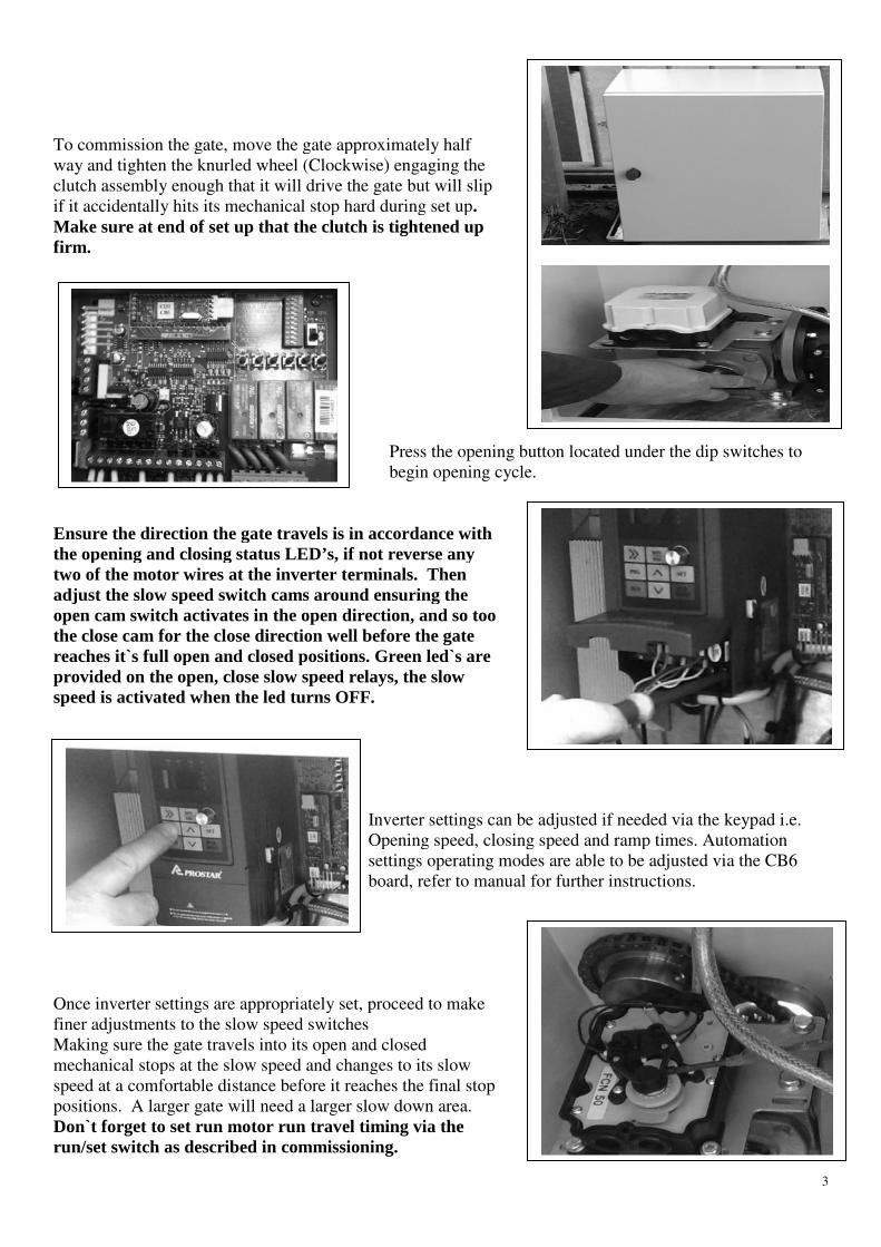
Once inverter settings are appropriately set, proceed to make
finer adjustments to the slow speed switches
Making sure the gate travels into its open and closed
mechanical stops at the slow speed and changes to its slow
speed at a comfortable distance before it reaches the final stop
positions. A larger gate will need a larger slow down area.
Don`t forget to set run motor run travel
run/set switch as described in commissioning.
To commission the gate, move the gate approximately half
way and tighten the knurled wheel (Clockwise) engaging the
clutch assembly enough that it will drive the gate but will slip
ccidentally hits its mechanical stop hard during set up.
Make sure at end of set up that the clutch is tightened up
Press the opening button located under the dip switches to
begin opening cycle.
Ensure the direction the gate travels is in accordance with
the opening and closing status LED’s, if not reverse any
two of the motor wires at the inverter terminals. Then
adjust the slow speed switch cams around ensuring the
open cam switch activates in the open direction, and so too
the close cam for the close direction well before the gate
s full open and closed positions. Green led`s are
pen, close slow speed relays, the slow
speed is activated when the led turns OFF.
Inverter settings can be adjusted if needed via the keypad i.e.
Opening speed, closing speed and ramp times. Automation
settings operating modes are able to be adjusted via the CB6
board, refer to manual for further instructions.
Once inverter settings are appropriately set, proceed to make
finer adjustments to the slow speed switches
Making sure the gate travels into its open and closed
stops at the slow speed and changes to its slow
speed at a comfortable distance before it reaches the final stop
positions. A larger gate will need a larger slow down area.
travel timing via the
commissioning.
3
Press the opening button located under the dip switches to
Inverter settings can be adjusted if needed via the keypad i.e.
Opening speed, closing speed and ramp times. Automation
le to be adjusted via the CB6
board, refer to manual for further instructions.
4
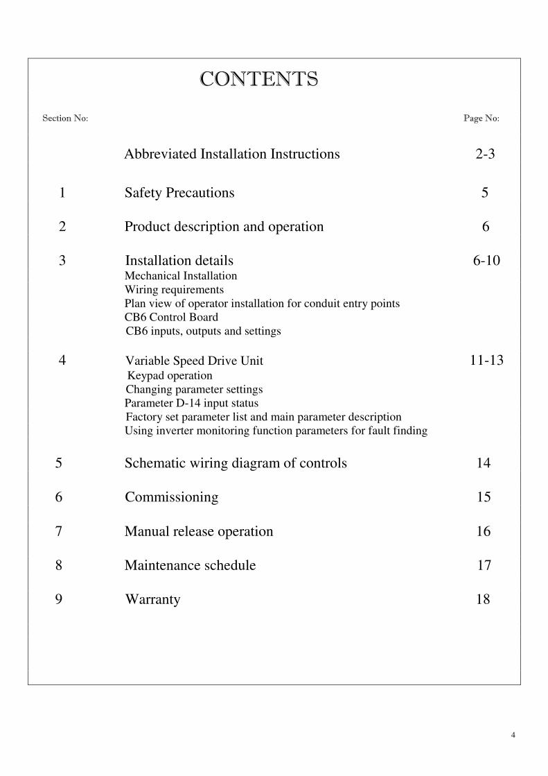
CONTENTS Section No: Page No:
Abbreviated Installation Instructions 2-3
1 Safety Precautions 5
2 Product description and operation 6
3 Installation details 6-10 Mechanical Installation
Wiring requirements
Plan view of operator installation for conduit entry points
CB6 Control Board
CB6 inputs, outputs and settings
4 Variable Speed Drive Unit 11-13 Keypad operation
Changing parameter settings
Parameter D-14 input status
Factory set parameter list and main parameter description
Using inverter monitoring function parameters for fault finding
5 Schematic wiring diagram of controls 14
6 Commissioning 15
7 Manual release operation 16
8 Maintenance schedule 17
9 Warranty 18

1. SAFETY PRECAUTIONS
WARNING! FAILURE TO FOLLOW TH
INSTRUCTIONS COULD RESULT IN INJURY OR D
EQUIPMENT.
• Appropriately licensed and competent personnel only should install the automation equipment.
• The operators are designed specifically to open and close sliding gates or doors and should not be used for any
other purpose.
• Before commencing installation, read through this installation manua
• Check that the operator and controls are in new condition and have not been damaged in transit.
• Check the gate or door and it`s associated support posts and walls to protect against shearing, compression and
other various traps which could cause serious
surrounding environment.
• Check the gateposts or mounting structure has the necessary strength and rigidity to support the operator and the
load of the opening and closing gate motion.
CAUTION!
Always incorporate the appropriate Photo Electric Cells, Induction Loops and any other safety devices to
protect both equipment and personnel. Extra caution should be employedclose mode.
• Display any necessary signs to indicate any danger areas and automatic operation of the gate or door.
• The operators are not designed to be used in any hazardous areas or areas subject to flooding etc.
• All electrical connections and wiring must be performed with AS/NZS 3000
counterpart for other countries outside of Australia and New Zealand)
WARNING! ELECTRICITY CAN KILL
• The manufacturer of the automation equipment is not responsi
the operator, gate or door and any other person or equipment when:
o Wrong or poor installation practices were performed.
o No or inadequate safety devices were used.
o Either the surrounding structure or the ga
hand.
o Inefficient locking devices were employed.
o Poor maintenance on the equipment.
o Any other circumstances beyond the manufacturers control.
• Isolate power before attempting any maintenanc
• Only original spare parts are to be used should there be a requirement for them.
• Keep loose clothing and hands clear of the gate whilst in operation or potentially able to be operated.
• The installer should provide all information concerning the use of the automation equipment as well as
instructions regarding the manual override and maintenance procedures to the users of the system
RECAUTIONS
FAILURE TO FOLLOW THESE SAFETY PRECAUTIONS AND INSTALLATION
ESULT IN INJURY OR DEATH AND/OR DAMAGE TO PROPERT
tent personnel only should install the automation equipment.
The operators are designed specifically to open and close sliding gates or doors and should not be used for any
Before commencing installation, read through this installation manual.
Check that the operator and controls are in new condition and have not been damaged in transit.
Check the gate or door and it`s associated support posts and walls to protect against shearing, compression and
other various traps which could cause serious injury or death. Take into consideration the general installation and
Check the gateposts or mounting structure has the necessary strength and rigidity to support the operator and the
load of the opening and closing gate motion.
Always incorporate the appropriate Photo Electric Cells, Induction Loops and any other safety devices to
protect both equipment and personnel. Extra caution should be employed when using operator in auto
Display any necessary signs to indicate any danger areas and automatic operation of the gate or door.
The operators are not designed to be used in any hazardous areas or areas subject to flooding etc.
al connections and wiring must be performed with AS/NZS 3000-2007 as the guidelines. (Or its
counterpart for other countries outside of Australia and New Zealand)
The manufacturer of the automation equipment is not responsible for the damage which may be caused to either
the operator, gate or door and any other person or equipment when: -
Wrong or poor installation practices were performed.
No or inadequate safety devices were used.
Either the surrounding structure or the gate or door strength and rigidity was not sufficient for the task in
Inefficient locking devices were employed.
Poor maintenance on the equipment.
Any other circumstances beyond the manufacturers control.
Isolate power before attempting any maintenance, qualified personnel only to carry out maintenance
Only original spare parts are to be used should there be a requirement for them.
Keep loose clothing and hands clear of the gate whilst in operation or potentially able to be operated.
uld provide all information concerning the use of the automation equipment as well as
instructions regarding the manual override and maintenance procedures to the users of the system
5
NS AND INSTALLATION
OR DAMAGE TO PROPERTY AND
tent personnel only should install the automation equipment.
The operators are designed specifically to open and close sliding gates or doors and should not be used for any
Check that the operator and controls are in new condition and have not been damaged in transit.
Check the gate or door and it`s associated support posts and walls to protect against shearing, compression and
injury or death. Take into consideration the general installation and
Check the gateposts or mounting structure has the necessary strength and rigidity to support the operator and the
Always incorporate the appropriate Photo Electric Cells, Induction Loops and any other safety devices to
when using operator in auto
Display any necessary signs to indicate any danger areas and automatic operation of the gate or door.
The operators are not designed to be used in any hazardous areas or areas subject to flooding etc.
2007 as the guidelines. (Or its
ble for the damage which may be caused to either
te or door strength and rigidity was not sufficient for the task in
e, qualified personnel only to carry out maintenance
Keep loose clothing and hands clear of the gate whilst in operation or potentially able to be operated.
uld provide all information concerning the use of the automation equipment as well as
instructions regarding the manual override and maintenance procedures to the users of the system

6
2. PRODUCT DESCRIPTION AND OPERATION. This operator has been developed in order to make installation, commissioning and gate operation as simple
and hassle free as possible without detracting from the quality that has always been the trademark of the GDS range of
operators.
Apart from the upgrade of inverter control to the Prostar unit the traditional limit switch type of system
which initiates the ramp down time period then stopping of the gate at the end has been changed to suit a wider range
of gate sizes without having to change chain drive sprocket sizes or limit gear ratios to match.
The chain driven cam switches are connected to initiate a second slow or homing speed which then at that
slow speed, the gate is allowed to drive into the post/mechanical stop smoothly, then after a programmed time delay,
the inverter detects a rise in current and signals the CB-6 board to stop that cycle of operation. With this method of
control, apart from the advantages over traditional limits described above, there is a more gentle or controlled stop
allowing easier aligning of electric gate contact switches, electric locks etc, and with no physical limit switches,
adjustment of the gates final stopping position will never need adjusting as long as the mechanical gate stops used are
adequate for the gate. Also, as long as the gate rack at operator drive pinion are in good order and adjusted correctly
with normal recommended maintenance, the slow down area shouldn’t need adjusting. Even if the rack does get out
of adjustment with the drive pinion, there will be a certain amount of room for error through the adequate adjustment
of the slow down area before the gate reaches the mechanical stop. Even if the gate ends up hitting the mechanical
stop at full speed either the inverter will detect the sudden current rise and cut power to the motor in turn displaying a
fault code on its display, and the clutch will slip.
The Prostar inverter has an advanced function parameter list with a detailed list of monitoring display
functions for both the operation of the inverter and status of the inputs to the inverter also with logging of the last 3
faults and recording of the operating conditions of the inverter at the first fault, taking some of the guess work out of
fault finding on site.
3. INSTALLATION DETAILS
Mechanical installation
• Ensure gate rolls easily and has been installed in a manner where there is no excessive friction or binding
occurring.
• IMPORTANT ensure there are gate stops firmly installed in the fully open and closed positions. These stops
need to be engineered and installed such that they will be strong enough to stop the gate should the limits fail at
any time.
• A concrete base approximately 650mm long x350 wide x 300mm deep should be laid where the gate operator is to
be located.
• Position operator in approximate mounting location.
• Use a section of rack to locate the operator the correct distance away from the gate rail (finer adjustment can be
made after).
• Dynabolt or chemical anchor the bottom mounting plate to the concrete mounting pad using 12 x 100mm fixings
through the slotted mounting holes.
• Unscrew anticlockwise the manual disconnect knurled knob so the drive gear free wheels.
• Fix the rack to the gate rail ensuring there is approximately 1mm - 2mm gap between the meshing of the teeth of
the rack and the drive gear (no more). Move the gate by hand from one end to the other while checking that the
rack is meshing correctly with the drive gear on the operator. Check also that the rack is centred around the middle
of the teeth on the drive cog – tighten the mounting plate nuts.

7
WIRING REQUIREMENTS
• 240v 10A non earth leakage protected power supply where operator is mounted. • Extra low voltage cables from operator to field equipment such as photo cells, access control etc, should be
shielded type cable if cable length is over 8m and especially if wiring runs directly next to high voltage cabling such
as mains power.
Electrical Cabling • A suitably rated Isolator and 240v power supply should be available near to where the gate operator is to be
mounted. The following diagrams will provide measurements for the positioning of conduits and the appropriate
position for mounting the operator whether a GDS 450 W or a GDS 630 W.
Electrical Connections • Connect a non earth leakage protected 10A 240v supply to Din Rail terminals labelled A & N, Connect earth to the
earth Din Rail terminal.
• Conduits for power & control need to preferably come up through the base plate 'knockout'.
Connections to Control Board • All control wiring associated with the inverter and low speed switching has been installed.
• Any external field wiring for photo cells, access control, locking etc will have to be connected to the appropriate
inputs and outputs on CB-6 board.
PLAN VIEW OF OPERATOR INSTALLATION FOR CONDUIT ENTRY POINTS
8
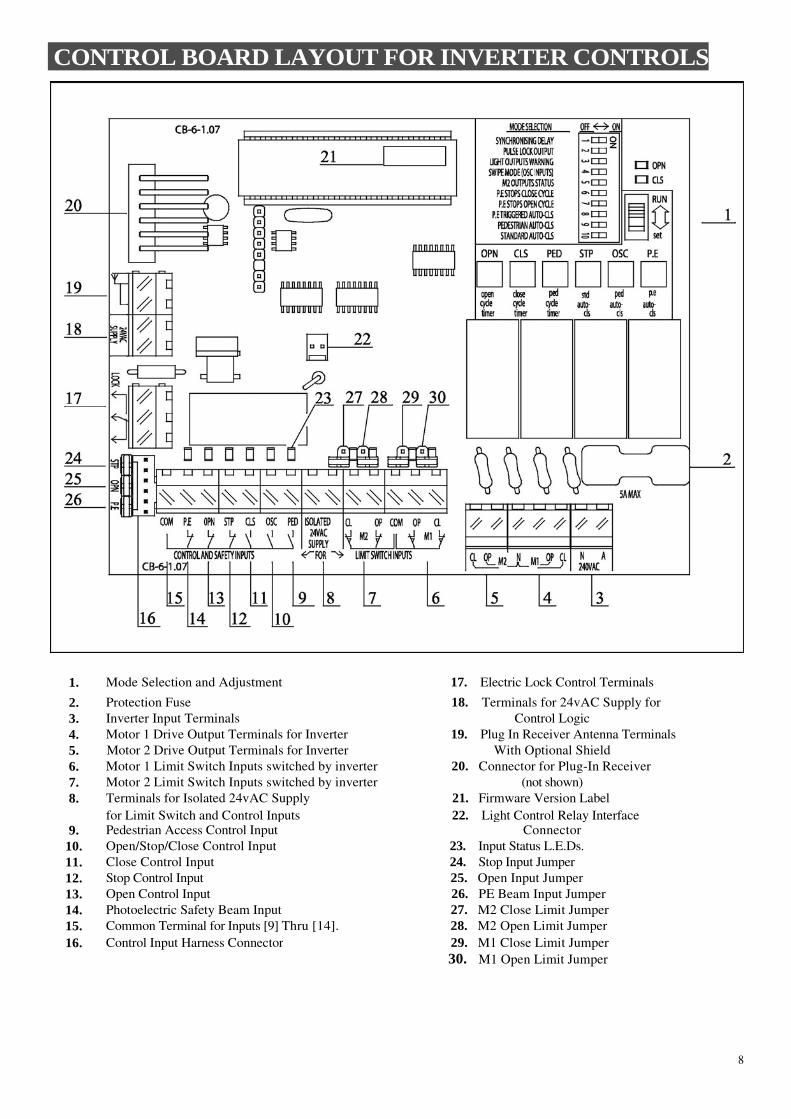
CONTROL BOARD LAYOUT FOR INVERTER CONTROLS
1. Mode Selection and Adjustment 17. Electric Lock Control Terminals
2. Protection Fuse 18. Terminals for 24vAC Supply for
3. Inverter Input Terminals Control Logic
4. Motor 1 Drive Output Terminals for Inverter 19. Plug In Receiver Antenna Terminals
5. Motor 2 Drive Output Terminals for Inverter With Optional Shield
6. Motor 1 Limit Switch Inputs switched by inverter 20. Connector for Plug-In Receiver
7. Motor 2 Limit Switch Inputs switched by inverter (not shown)
8. Terminals for Isolated 24vAC Supply 21. Firmware Version Label
for Limit Switch and Control Inputs 22. Light Control Relay Interface 9. Pedestrian Access Control Input Connector
10. Open/Stop/Close Control Input 23. Input Status L.E.Ds.
11. Close Control Input 24. Stop Input Jumper
12. Stop Control Input 25. Open Input Jumper
13. Open Control Input 26. PE Beam Input Jumper
14. Photoelectric Safety Beam Input 27. M2 Close Limit Jumper
15. Common Terminal for Inputs [9] Thru [14]. 28. M2 Open Limit Jumper
16. Control Input Harness Connector 29. M1 Close Limit Jumper
30. M1 Open Limit Jumper

9
Control Inputs The P.E, OPN and STP inputs require a normally closed switch contact and therefore should be shorted to the COM
terminal if not used. This is done via bridging links already on the circuit board (bottom left corner) The CLS, OSC
and PED inputs require a normally open switch contact and therefore should be left unconnected if not used. All the
switch inputs of this control board including the limit switch inputs require a switch contact only. Do not connect any
switches which provide a voltage to the control board as this will damage the control board. If the desired inputs are
12/24v or has long wiring associated with it use an IM-1 module to isolate it from the control board’s input. The IM-1
is available from the manufacturer.
Powering Accessories Accessories which require a 24v AC supply can be powered from the transformer output used to power the control
board via the isolated 24v AC supply which is connected to the DIN rail terminals as labelled. However, the
transformer’s current capacity must be checked to allow for the extra power required by the accessories. Never use the
supply connected to the 24v AC supply control board terminals to power any accessory as this can interfere with the
control boards operation. (Blue Wires)
Locks & Lights Use the lock output terminals on the din rail to switch the 12 volts to an electric lock (if fitted). The load switched by
the lock output terminals must not exceed 30V A.C / D.C @ 5Amps. If an electromagnetic lock is used, change one
wire on the control board lock output to the normally closed output. Use the light relay module (if fitted) to switch the
applied voltage to a light. The load switched by the light relay module must not exceed 240V A.C / 30V D.C @ 10
Amps.
Mode Selection Using the mode selection dip-switches select the desired operating modes. Note the times associated with the
parameters marked with an * can be changed. The auto-close times can be changed using the procedure in the
following section. See the instruction manual for details on how to change the other parameters.
See the detailed instruction manual for details on how to change the other parameters.
Position 1 SYNCHRONISING DELAY
OFF - No delay
ON - Motor 1 starts to open 2 seconds* before Motor 2 and Motor 2 starts to close 2 seconds* before Motor 1.
Position 2 PULSE LOCK OUTPUT
OFF - Lock output is activated for the entire motor drive cycle.
ON - Lock output pulses for 0.3 seconds* at the start of each drive cycle.
Position 3 LIGHT OUTPUTS WARNING
OFF - Optional light module controls a light with timer which turns light off after 60seconds*.
ON - Optional light module controls a warning light which activates whenever motors are on.
Position 4 SWIPE MODE (OSC INPUT)
OFF - OSC input terminal has standard Open, Close, Stop action.
ON - OSC input terminal will only open the door/gate. The input also resets the P.E triggered
auto-close mode so that the P.E input will need to be triggered again before a P.E auto-
close cycle will be initiated.
Position 5 M 2 OUTPUTS STATUS
OFF - The M2 output controls second motor
ON - The M2 output controls status light
Position 6 P.E STOPS CLOSE CYCLE
OFF - Activating the P.E input while motors are closing causes the motors to reverse.
ON - Activating the P.E input while motors are closing causes the motors to stop but not reverse.
Position 7 P.E STOPS OPEN CYCLE
OFF - Activating the P.E input while motors are opening is ignored by the controller.
ON - Activating the P.E input while motors are opening causes the motors to stop.
10
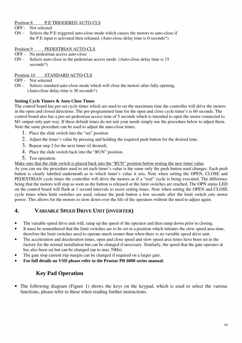
Position 8 P.E TRIGGERED AUTO-CLS
OFF - Not selected
ON - Selects the P.E triggered auto-close mode which causes the motors to auto-close if
the P.E input is activated then released. (Auto-close delay time is 0 seconds*)
Position 9 PEDESTRIAN AUTO-CLS
OFF - No pedestrian access auto-close
ON - Selects auto-close in the pedestrian access mode. (Auto-close delay time is 15
seconds*)
Position 10 STANDARD AUTO-CLS
OFF - Not selected
ON - Selects standard auto-close mode which will close the motors after fully opening.
(Auto-close delay time is 30 seconds*)
Setting Cycle Timers & Auto Close Times The control board has pre-set cycle times which are used to set the maximum time the controller will drive the motors
in the open and closed directions. The pre-programmed time for the open and close cycle timer’s is 60 seconds. The
control board also has a pre-set pedestrian access time of 5 seconds which is intended to open the motor connected to
M1 output only part way. If these default times do not suit your needs simply use the procedure below to adjust them.
Note the same procedure can be used to adjust the auto-close times.
1. Place the slide switch into the “set” position
2. Adjust the timer’s value by pressing and holding the required push button for the desired time.
3. Repeat step 2 for the next timer (if desired).
4. Place the slide switch back into the “RUN” position.
5. Test operation.
Make sure that the slide switch is placed back into the “RUN” position before testing the new timer value.
As you can see the procedure used to set each timer’s value is the same only the push button used changes. Each push
button is clearly labelled underneath as to which timer’s value it sets. Note when setting the OPEN, CLOSE and
PEDESTRIAN cycle times the controller will drive the motors as if a “real” cycle is being executed. The difference
being that the motors will stop as soon as the button is released or the limit switches are reached. The OPN status LED
on the control board will flash at 1 second intervals to assist setting times. Note when setting the OPEN and CLOSE
cycle times when limit switches are used, release the push button a few seconds after the limit switch cuts motor
power. This allows for the motors to slow down over the life of the operators without the need to adjust again.
4. VARIABLE SPEED DRIVE UNIT (INVERTER) • The variable speed drive unit will, ramp up the speed of the operator and then ramp down prior to closing.
• It must be remembered that the limit switches are to be set in a position which initiates the slow speed area time,
therefore the limit switches need to operate much sooner than when there is no variable speed drive unit.
• The acceleration and deceleration times, open and close speed and slow speed area times have been set in the
factory for the normal installation but can be changed if necessary. Similarly, the speed that the gate operates at
has also been set but can be changed (up to max 70Hz).
• The gate stop current trip margin can be changed if required on a larger gate.
• For full details on VSD please refer to the Prostar PR 6000 series manual.
Key Pad Operation • The following diagram (Figure 1) shows the keys on the keypad, which is used to select the various
functions, please refer to these when reading further instructions.
11
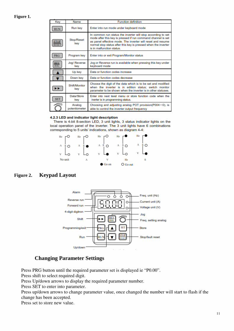
Figure 1.
Figure 2. Keypad Layout
Changing Parameter Settings
Press PRG button until the required parameter set is displayed ie “P0.00”.
Press shift to select required digit.
Press Up/down arrows to display the required parameter number.
Press SET to enter into parameter.
Press up/down arrows to change parameter value, once changed the number will start to flash if the
change has been accepted.
Press set to store new value.

12
Once new value has been stored, you can navigate to the next parameter if required by the arrow and
shift buttons, or press program button until back to the main running screen.ie “0.00” with the Hz
indicator lit up on the top right of screen.
Using inverter monitoring parameters for monitoring and fault finding • From the main screen “0.00” press the PRG button once to get to the parameter menu screen “D-00”.
• Use >> button to select required digit on screen to change then scroll that digit up or down with the up/down ↕
button.
• Use up/down ↕ buttons to get to the required parameter number, once number selected, press “SET” to enter into
required parameter. The screen will display the information for that parameter number.
Selection of handy parameters to use: *full list shown in Prostar PR 6000 series inverter manual.
D-19 to D-21 = Last 3 fault records *handy especially if the power has been turned off after a fault and you need to
Know what the fault code was.
D-15 to D-16 = Temperature reading *Check if suspected overheating of inverter.
Inverter components
D-14 = Inverter input terminal *Used to check that the inverter is receiving the correct signal
Status from the CB-6 Board, in this way you can determine if the
existing fault is related to either the CB-6 board or the inverter.
If the inverter goes into fault mode, it will display the fault as a code between E-00 to E-18, please refer to the Prostar manual on pages 122 to 124 for the description of each fault code.
*Use diagram below to determine status of the inverter inputs, LED display segments represent each input.
Parameter D-14 = Input Terminal Status

13
Prostar PR600 Inverter parameter list for Pro Operator
Parameter list number
Definition
Setting
P0.01 Keypad up/down button
frequency control
1
P0.06 Upper limit frequency 70
P0.03 Opening speed 60
P0.04 Running command via
terminals
1
P0.09 Max output voltage 230
P0.14 Acceleration time 5.0
P0.15 Deceleration time 2.5
P2.19 Slow speed jog running
frequency
12
P2.20 Jog acceleration time 1.5
P2.21 Jog deceleration time 1.5
P2.28 Closing speed 30 (630 LI PRO)
40 (450 LI PRO)
P4.00 Closing Speed
Input terminal DI1
1
P4.01 Opening slow speed jog
terminal DI2
9
P4.02 Closing slow speed jog
terminal D13
10
P4.09 Programmable relay output
Inverter overload alarm set
8
P4.13 Overload pre alarm
Checkout level percent
60
P4.14 Overload pre alarm
Delayed time
3.0
14
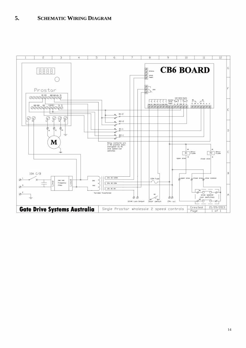
5. SCHEMATIC WIRING DIAGRAM
15
6. Commissioning
• From the factory, the operator is set up so that the gate opens up from right to left when looking at it from inside
the property, so that the operator is mounted on the left hand side of the driveway. The slow down switches are
set up so that the top switch controls the open slow speed, and the bottom switch operates the close slow speed, it
is important that they remain set up this way. If the gate operator is to be installed as a right hand open, the
switch cams will have to be turned around so they approach the micro switches from the other direction.
The open and close slow speed relays have a green indication LED. When an LED turns OFF, this is an indication that the slow speed switch has been activated. Taking note of this indication will tell you that the
correct slow speed direction has been selected for the correct gate direction.
• Adjust the slow speed switches so that they activate at approx 800mm from the full open and close positions.
Finer adjustment can be made once the gate is running.
• Manually push the gate to the half way position, and turn the clutch wheel clockwise to engage the clutch, tighten
it just enough so as it will drive the gate, but will slip if the gate hits something at full speed while
commissioning. (make sure to tighten it fully once commissioning is complete).
• If safe to do so, turn on power. (Use of a portable generator is forbidden as damage to inverter may result
from use).
• Check the gate drives in the right direction by pressing the either the opn,or cls buttons, either the opn or cls led`s will start to flash indicating that the gate is moving in the open or close direction. If the gate is
moving backwards, turn off the power to the operator, wait for the inverter power to drop out, then swap
any two of the motor phase wires at the inverter. Then move the slow speed cam lobs around to the opposite
sides of the slow speed switches, making sure that the top switch is for the open slow speed and the bottom
switch is for the close slow speed, taking note of the status of the slow speed open and close slow speed relay led
indicators.
• Once satisfied that the gate is travelling in the right direction, drive the gate fully open and closed to check if the
slow speed switches are set correctly.
• The slow speed switches should not activate too soon, but more importantly, not too late. In this way the gate
will have plenty of time to ramp down to the more controlled slow speed ready to be driven into the post and not
to bang into the post which will cause the clutch to slip, pre- maturely wearing the clutch friction discs.
• Now set the motor run time by first driving the gate to the closed position, turn the run/set switch into set, press
and hold the opn button to drive the gate fully open, once it reaches the full open position, keep the button
pressed for a further 5 seconds, then release. Do the same again for the close direction via the cls button, once
finished, turn the run/set switch back to run.
• Tighten clutch wheel.
• Test photo cell operation and any other safety device is operating correctly.
• Install cover using screws provided in the front and sides to hold cover firm.
• Provide full details to the owner concerning the operation and relevant maintenance and disconnect details.

7. MANUAL RELEASE I
Place key in door lock, turn clockwise till released and pull door open
Turn knurled knob anticlockwise approx. ½ a turn to release
To re-engage the clutch, move the gate by hand
Into approx. The half way position and turn the
Knurled knob clockwise until it is very tight.
If, when turning the knurled knob clockwise and
It just spins, either, try spinning it clockwise with
more force to release it off of the hexagonal
nut or hold the nut with one hand and turn
knob clockwise.
INSTRUCTIONS
Place key in door lock, turn clockwise till released and pull door open
Turn knurled knob anticlockwise approx. ½ a turn to release
Gate can now be opened by hand.
engage the clutch, move the gate by hand
lf way position and turn the
Knurled knob clockwise until it is very tight.
If, when turning the knurled knob clockwise and
It just spins, either, try spinning it clockwise with
more force to release it off of the hexagonal retaining
ith one hand and turn the knurled
16
Place key in door lock, turn clockwise till released and pull door open.

8. MAINTENANCE DETAILS
WARNING!
Failure to maintain equipment may result in injury or death and/or damage to property and equipment
Recommended maintenance to be performed on the operator
Operator performs over 150 cycles a day
Operator performs between 100
Operator performs between 50-
Operator performs between 20-
Operator performs under 20 cycles a day
Date: ................................................................
Site Name: ................................................................
Site Address: ................................................................
Before commencing maintenance on the operator, isolate the electrical supply to ensure operator will not run
inadvertently.
Gate rolls freely when in ma
Gate wheels and guide rollers in good condition
Gate stops in good condition and not loose
Gate rack is tight & correct clearances between pinion wheel & rack
Gate track is not damaged ................................
Gate operator mounting bolts right
No oil leaks from gearboxes
Gearbox mounting bolts/nuts tight
Inside operator and control box clean
‘Baygon’ Surface Spray around operator and control box (not on electronics)
All electrical connections tight
Limit Switches operate in appropriate positio
External safety devices work effectively / cleaned
Electromagnetic lock, if fitted, operates correctly and is clean
Wash down of control box and cover (particularly near corrosive/ sea environments.....
General operation i.e. speed, auto close etc normal
Comments ................................................................
................................................................
................................................................
Service performed by ................................
ETAILS
Failure to maintain equipment may result in injury or death and/or damage to property and equipment
Recommended maintenance to be performed on the operator and gate are as follows:-
Operator performs over 150 cycles a day each month
Operator performs between 100-150 cycles a day every 2 month
-99 cycles a day every 4 months
-49 cycles a day every 6 months
Operator performs under 20 cycles a day every 12 months
..............................................................
................................................................................................
................................................................................................
commencing maintenance on the operator, isolate the electrical supply to ensure operator will not run
Gate rolls freely when in manual .....................................................................................
Gate wheels and guide rollers in good condition .............................................................
Gate stops in good condition and not loose ................................................................
Gate rack is tight & correct clearances between pinion wheel & rack ............................
................................................................................................
Gate operator mounting bolts right ................................................................
............................................................................................
Gearbox mounting bolts/nuts tight ................................................................
Inside operator and control box clean ................................................................
‘Baygon’ Surface Spray around operator and control box (not on electronics)
All electrical connections tight ........................................................................................
Limit Switches operate in appropriate positions/ chain oiled ................................
External safety devices work effectively / cleaned ..........................................................
Electromagnetic lock, if fitted, operates correctly and is clean ................................
Wash down of control box and cover (particularly near corrosive/ sea environments.....
ed, auto close etc normal ........................................................
................................................................................................
..............................................................................................................................
..............................................................................................................................
...........................................................................................................................17
Failure to maintain equipment may result in injury or death and/or damage to property and equipment
..........................................................
......................................................
commencing maintenance on the operator, isolate the electrical supply to ensure operator will not run
..................... �
............................. �
..................................... �
............................ �
................................ �
.................................................. �
............................ �
.................................................. �
.............................................. �
‘Baygon’ Surface Spray around operator and control box (not on electronics) .............. �
........................ �
.......................................... �
.......................... �
....................................... �
Wash down of control box and cover (particularly near corrosive/ sea environments.....�
........................ �
............................................
..............................
..............................
...........................

18
9. WARRANTY
a. Gate Drive Systems Australia warrants that the goods manufactured by it shall be free from defect in
manufacture for a period of 12 months from the date of invoice. Should any fault occur within that period as a
result of faulty workmanship or materials, Gate Drive Systems Australia will at its discretion, replace the
product at no charge to the Customer except for installation and freight. The appropriate Serial Number must
be quoted for all warranty claims.
b. For the goods not manufactured by Gate Drive Systems Australia, we shall pass on the manufacturers warranty
to the Customer from the date of invoice. It is at the manufacturers discretion to repair or replace goods deemed
to be defective as a result of faulty workmanship or materials.
c. All goods must be returned to Gate Drive Systems Australia or its representative for inspection or testing to
assess if a claim is justified. It is the responsibility and at the cost of the Customer, to remove and return the
goods for inspection and freight costs are the responsibility of the Customer.
d. The warranty is negated and will not apply in the following circumstances:-
i. If no proof of date of purchase can be produced.
ii. If the product has been used in a manner beyond its design parameters.
iii. If the product is tampered with or repaired by personnel not authorised to do so.
iv. In respect of loss or damage caused by rough treatment.
v. If the product is not used and maintained in accordance with instructions or recommendations listed in
this Installation and Maintenance Manual.
vi. In respect of loss or damage caused by an Act of God or any other cause not within the manufacturers
control.
e. Goods returned under warranty for repair or testing will incur a charge to be fixed by the manufacturer if no
fault is found.
f. The Customer shall bear freight charges for removing and returning the goods for inspection and for the
delivery and installation of any replacement or repaired product from a justified warranty claim.
g. Save for the express conditions and warranties herein contained all other conditions or warranties (whether as
the quality, fitness for purpose or any other matter) expressed or implied by statute, common law, equity, trade
custom, usage or otherwise are hereby expressly excluded provided that nothing in these terms and conditions
shall exclude or limit any breach or condition implied by law, the exclusion or limitation of which is not
permitted by law.