Embed Size (px)
Citation preview
SAFETY FIRST!
High voltage and rotating parts can cause serious injury or loss of life. Installation, operation and maintenance
must be performed by qualified personnel. Familiarization with and adherence to NEMA† MG2, the National
Electric Code, and local codes is recommended. It is important to observe safety precautions to protect personnel from possible injury. Personnel should be instructed to:
TITAN®II Horizontal Large AC Electric Motors
INSTALLATION, OPERATION AND MAINTENANCE MANUAL
Save this instruction manual for future reference.
P/N 986240 Rev. 08/11
HORIZONTAL SLEEVE BEARING OPEN DRIPPROOF, WPI, WPII MOTOR ENCLOSURE
1
INSTALLATION AND MAINTENANCE
www.usmotors.com Nidec Motor Corporation
SAEFTY FIRST!
High voltage and rotating parts can cause serious injury or loss of life. Installation, operation and maintenance must be performed by qualified personnel. Familiarization with and adherence to NEMA®†
MG2, the National Electric Code and local codes is recommended. It is important to observe safety precautions to protect personnel from possible injury. Personnel should be instructed to:
1. Disconnect all power to motor and accessories prior to initiating any installation, maintenance or repairs. Also ensure that driven equipment connected to the motor shaft will not cause the motor to rotate (windmilling of fans, water flowing back through pump, etc.).
2. Avoid contact with rotating parts.
3. Act with care in accordance with this manual’s prescribed procedures in handling and installing this equipment.
4. Be sure unit and accessories are electrically grounded and proper electrical installation wiring and controls are used in accordance with local and national electrical codes. Refer to “National Electrical Code Handbook” – NFPA No. 70. Employ qualified electricians.
5. Be sure equipment is properly enclosed to prevent access by children or other unauthorized
personnel in order to prevent possible accidents.
6. Be sure shaft key is fully captive before unit is energized.
7. Provide proper safeguards for personnel against rotating parts and applications involving high inertia loads, which cause overspeed.
8. Avoid extended exposure to equipment with high noise levels.
9. Observe good safety habits at all times and use care to avoid injury to yourself or damage to
equipment.
10. Be familiar with the equipment and read all instructions thoroughly before installing or working on equipment.
11. Observe all special instructions attached to the equipment. Remove shipping fixtures, if so
equipped, before energizing unit.
12. Check motor and driven equipment for proper rotation and phase sequence prior to coupling. Also check if a unidirectional motor is supplied and note proper rotation.
13. Electric motors can retain a lethal charge even after being shut off. Certain accessories (space
heaters, etc.) are normally energized when the motor is turned off. Other accessories such as power factor correction capacitors, surge capacitors, etc. can retain an electrical charge after being shut off and disconnected.
14. Do not apply power correction capacitors to motors rated for operation with variable frequency
drives. Serious damage to the drive will result if capacitors are placed between the motor and drive. Consult drive supplier for further information.
Safety
2
www.usmotors.com Nidec Motor Corporation
INSTALLATION AND MAINTENANCE
SECTION PAGE
SAFETY ……………………………………………………………………………………..…..…………….. 1
TABLE OF CONTENTS ……………………………….…………………………………..…..…………….. 2
1. SHIPMENT ……………………………………………………………………………………..………… 3
2. HANDLING ………………….…………………………………………………………………………… 3
3. STORAGE ……………………………………………………………………………………………….. 4
3.1 When to put a motor in storage …………………………………………………………………... 4
3.2 Storage Preparation ………………………………….…………………………………………….. 4
3.3 Periodic Maintenance ………………………………..…………..………………………………… 5
3.4 Start-up Preparations After Storage ……………………………………………………………… 7
4. INSTALLATION LOCATION ………………….……………………………………………………….. 8
5. FOUNDATION …………………………………………………………………………………….…….. 8
5.1 Grouting ………...…………………………………………………………………………………… 9
6. INITIAL INSTALLATION ………………………….…………………………………………….……… 9
6.1 Coupling Installation ……………………………….……...……...……………..…..................… 9
6.2 Rough Alignment …………………….……………………...……...…….……………….………. 10
6.3 Final Alignment …………………….…………………………...…………………..……………… 10
6.4 Coupling Requirements …………………………………….………..………….………………… 11
6.5 Electrical Connection ……………………………………………..………………………..……… 12
6.6 Reversing Rotation …………….………………….………....…..…….……………….….……… 12
6.7 Initial Start ………………………….…………….…….…………..………...………….….……… 13
6.8 Vibration ……………………………….……………………….……….…………………...……… 14
6.9 Doweling …………………….………...……………………….………….…………………...…… 14
7. ROUTINE MAINTENANCE …………….………………….………………………………………..…. 15
7.1 General Maintenance ……………….……………………..…….……..……….………….…...… 15
7.2 Inspection and Cleaning ……………………………..……………...……………………….……. 15
7.3 Bearings ……………………………….…………………...……...…….…….………….………… 16
7.4 Bearing Insulation ………..………………………………………………………………………… 16
7.5 Bearing Lubrication…………………………..…………………………………………….………. 16
7.6 Bearing Replacement………...……………………………………………………………………. 17
8. RENEWAL PARTS AND SERVICE ……………………………………………..….………………… 22
9. CUTAWAY DRAWINGS ………………………………………………………………………………... 23
10. TROUBLESHOOTING ………………………………………..…...……………..………….….……… 24
11. INSTALLATION RECORD ………………………………………..…...…….…..…….………….…… 27
Table of Contents
3
www.usmotors.com Nidec Motor Corporation
INSTALLATION AND MAINTENANCE
1. SHIPMENT
Prior to shipment, all TITAN II Line Motors undergo extensive electrical and mechanical testing, and are thoroughly inspected. Upon receipt of the motor, carefully inspect the unit for any signs of damage that may have occurred during shipment. Should such damage be evident, unpack the motor at once in the presence of a claims adjuster and immediately report all damage and breakage to the transportation company and Nidec Motor Corporation. When contacting Nidec Motor Corporation concerning the motor, be sure to include the complete motor identification number, frame and type which appears on the nameplate (see installation record in this manual).
2. HANDLING
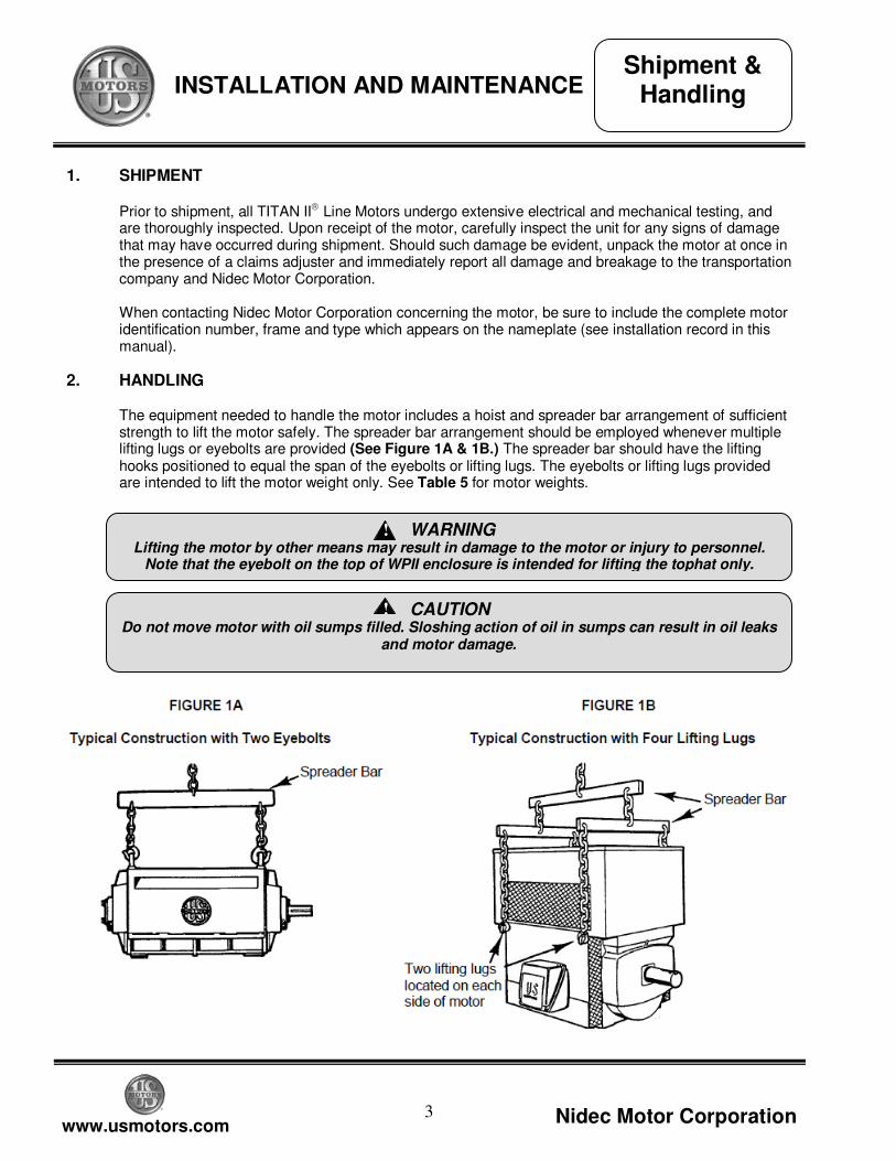
The equipment needed to handle the motor includes a hoist and spreader bar arrangement of sufficient strength to lift the motor safely. The spreader bar arrangement should be employed whenever multiple lifting lugs or eyebolts are provided (See Figure 1A & 1B.) The spreader bar should have the lifting hooks positioned to equal the span of the eyebolts or lifting lugs. The eyebolts or lifting lugs provided are intended to lift the motor weight only. See Table 5 for motor weights.
Lifting the motor by other means may result in damage to the motor or injury to personnel.
Note that the eyebolt on the top of WPII enclosure is intended for lifting the tophat only.
WARNING
!
Do not move motor with oil sumps filled. Sloshing action of oil in sumps can result in oil leaks
and motor damage.
CAUTION
!
Shipment & Handling
4
www.usmotors.com Nidec Motor Corporation
INSTALLATION AND MAINTENANCE
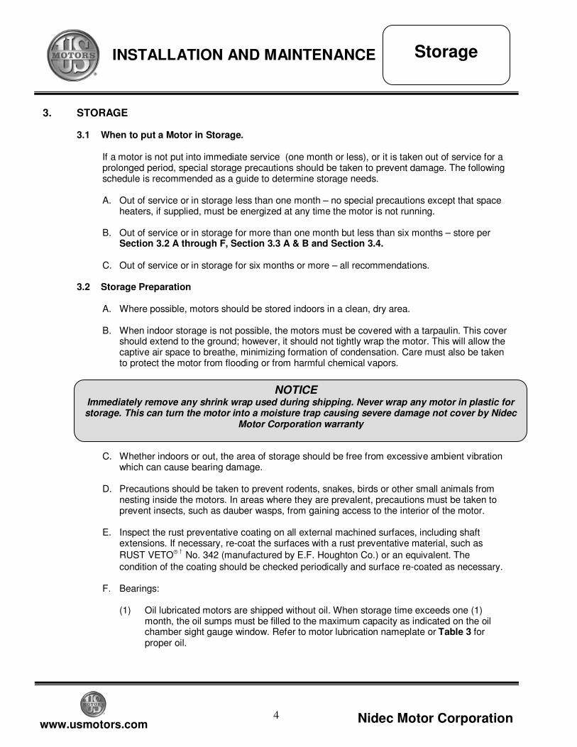
3. STORAGE
3.1 When to put a Motor in Storage.
If a motor is not put into immediate service (one month or less), or it is taken out of service for a prolonged period, special storage precautions should be taken to prevent damage. The following schedule is recommended as a guide to determine storage needs. A. Out of service or in storage less than one month – no special precautions except that space
heaters, if supplied, must be energized at any time the motor is not running. B. Out of service or in storage for more than one month but less than six months – store per
Section 3.2 A through F, Section 3.3 A & B and Section 3.4.
C. Out of service or in storage for six months or more – all recommendations.
3.2 Storage Preparation
A. Where possible, motors should be stored indoors in a clean, dry area. B. When indoor storage is not possible, the motors must be covered with a tarpaulin. This cover
should extend to the ground; however, it should not tightly wrap the motor. This will allow the captive air space to breathe, minimizing formation of condensation. Care must also be taken to protect the motor from flooding or from harmful chemical vapors.
C. Whether indoors or out, the area of storage should be free from excessive ambient vibration
which can cause bearing damage. D. Precautions should be taken to prevent rodents, snakes, birds or other small animals from
nesting inside the motors. In areas where they are prevalent, precautions must be taken to prevent insects, such as dauber wasps, from gaining access to the interior of the motor.
E. Inspect the rust preventative coating on all external machined surfaces, including shaft
extensions. If necessary, re-coat the surfaces with a rust preventative material, such as
RUST VETO† No. 342 (manufactured by E.F. Houghton Co.) or an equivalent. The
condition of the coating should be checked periodically and surface re-coated as necessary.
F. Bearings:
(1) Oil lubricated motors are shipped without oil. When storage time exceeds one (1) month, the oil sumps must be filled to the maximum capacity as indicated on the oil chamber sight gauge window. Refer to motor lubrication nameplate or Table 3 for proper oil.
Immediately remove any shrink wrap used during shipping. Never wrap any motor in plastic for storage. This can turn the motor into a moisture trap causing severe damage not cover by Nidec
Motor Corporation warranty
NOTICE
Storage
5
www.usmotors.com Nidec Motor Corporation
INSTALLATION AND MAINTENANCE
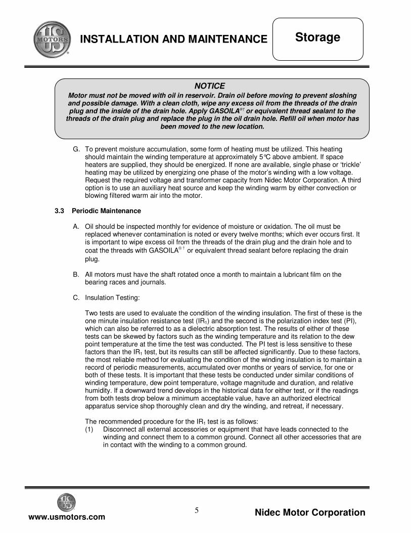
G. To prevent moisture accumulation, some form of heating must be utilized. This heating
should maintain the winding temperature at approximately 5°C above ambient. If space heaters are supplied, they should be energized. If none are available, single phase or ‘trickle’ heating may be utilized by energizing one phase of the motor’s winding with a low voltage. Request the required voltage and transformer capacity from Nidec Motor Corporation. A third option is to use an auxiliary heat source and keep the winding warm by either convection or blowing filtered warm air into the motor.
3.3 Periodic Maintenance
A. Oil should be inspected monthly for evidence of moisture or oxidation. The oil must be
replaced whenever contamination is noted or every twelve months; which ever occurs first. It is important to wipe excess oil from the threads of the drain plug and the drain hole and to
coat the threads with GASOILA† or equivalent thread sealant before replacing the drain
plug. B. All motors must have the shaft rotated once a month to maintain a lubricant film on the
bearing races and journals.
C. Insulation Testing:
Two tests are used to evaluate the condition of the winding insulation. The first of these is the one minute insulation resistance test (IR1) and the second is the polarization index test (PI), which can also be referred to as a dielectric absorption test. The results of either of these tests can be skewed by factors such as the winding temperature and its relation to the dew point temperature at the time the test was conducted. The PI test is less sensitive to these factors than the IR1 test, but its results can still be affected significantly. Due to these factors, the most reliable method for evaluating the condition of the winding insulation is to maintain a record of periodic measurements, accumulated over months or years of service, for one or both of these tests. It is important that these tests be conducted under similar conditions of winding temperature, dew point temperature, voltage magnitude and duration, and relative humidity. If a downward trend develops in the historical data for either test, or if the readings from both tests drop below a minimum acceptable value, have an authorized electrical apparatus service shop thoroughly clean and dry the winding, and retreat, if necessary.
The recommended procedure for the IR1 test is as follows: (1) Disconnect all external accessories or equipment that have leads connected to the
winding and connect them to a common ground. Connect all other accessories that are in contact with the winding to a common ground.
Storage
Motor must not be moved with oil in reservoir. Drain oil before moving to prevent sloshing and possible damage. With a clean cloth, wipe any excess oil from the threads of the drain plug and the inside of the drain hole. Apply GASOILA®†
or equivalent thread sealant to the threads of the drain plug and replace the plug in the oil drain hole. Refill oil when motor has
been moved to the new location.
NOTICE
6
www.usmotors.com Nidec Motor Corporation
INSTALLATION AND MAINTENANCE
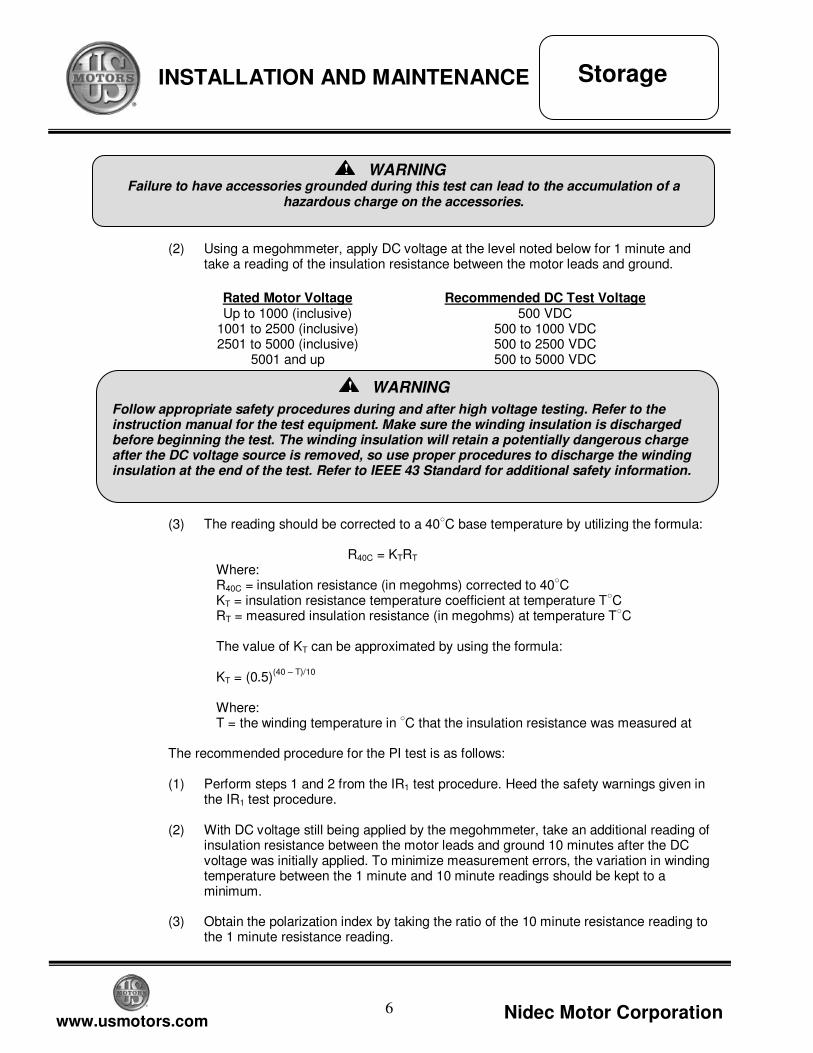
(2) Using a megohmmeter, apply DC voltage at the level noted below for 1 minute and
take a reading of the insulation resistance between the motor leads and ground.
(3) The reading should be corrected to a 40○C base temperature by utilizing the formula:
R40C = KTRT
Where: R40C = insulation resistance (in megohms) corrected to 40
○C
KT = insulation resistance temperature coefficient at temperature T○C
RT = measured insulation resistance (in megohms) at temperature T○C
The value of KT can be approximated by using the formula: KT = (0.5)
(40 – T)/10
Where: T = the winding temperature in
○C that the insulation resistance was measured at
The recommended procedure for the PI test is as follows: (1) Perform steps 1 and 2 from the IR1 test procedure. Heed the safety warnings given in
the IR1 test procedure. (2) With DC voltage still being applied by the megohmmeter, take an additional reading of
insulation resistance between the motor leads and ground 10 minutes after the DC voltage was initially applied. To minimize measurement errors, the variation in winding temperature between the 1 minute and 10 minute readings should be kept to a minimum.
(3) Obtain the polarization index by taking the ratio of the 10 minute resistance reading to
the 1 minute resistance reading.
Failure to have accessories grounded during this test can lead to the accumulation of a
hazardous charge on the accessories.
WARNING
!
Rated Motor Voltage Up to 1000 (inclusive)
1001 to 2500 (inclusive) 2501 to 5000 (inclusive)
5001 and up
Recommended DC Test Voltage 500 VDC
500 to 1000 VDC 500 to 2500 VDC 500 to 5000 VDC
Storage
Follow appropriate safety procedures during and after high voltage testing. Refer to the instruction manual for the test equipment. Make sure the winding insulation is discharged before beginning the test. The winding insulation will retain a potentially dangerous charge after the DC voltage source is removed, so use proper procedures to discharge the winding insulation at the end of the test. Refer to IEEE 43 Standard for additional safety information.
WARNING
!
7
www.usmotors.com Nidec Motor Corporation
INSTALLATION AND MAINTENANCE
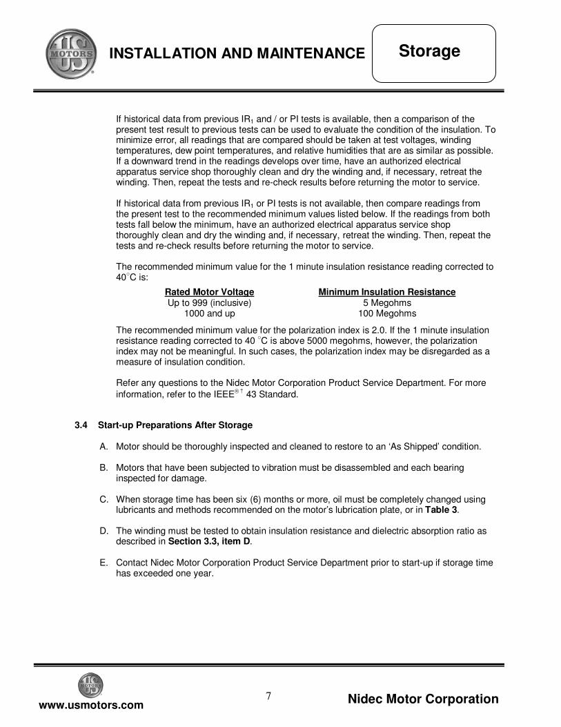
If historical data from previous IR1 and / or PI tests is available, then a comparison of the present test result to previous tests can be used to evaluate the condition of the insulation. To minimize error, all readings that are compared should be taken at test voltages, winding temperatures, dew point temperatures, and relative humidities that are as similar as possible. If a downward trend in the readings develops over time, have an authorized electrical apparatus service shop thoroughly clean and dry the winding and, if necessary, retreat the winding. Then, repeat the tests and re-check results before returning the motor to service. If historical data from previous IR1 or PI tests is not available, then compare readings from the present test to the recommended minimum values listed below. If the readings from both tests fall below the minimum, have an authorized electrical apparatus service shop thoroughly clean and dry the winding and, if necessary, retreat the winding. Then, repeat the tests and re-check results before returning the motor to service. The recommended minimum value for the 1 minute insulation resistance reading corrected to 40
○C is:
The recommended minimum value for the polarization index is 2.0. If the 1 minute insulation resistance reading corrected to 40
○C is above 5000 megohms, however, the polarization
index may not be meaningful. In such cases, the polarization index may be disregarded as a measure of insulation condition. Refer any questions to the Nidec Motor Corporation Product Service Department. For more
information, refer to the IEEE† 43 Standard.
3.4 Start-up Preparations After Storage A. Motor should be thoroughly inspected and cleaned to restore to an ‘As Shipped’ condition. B. Motors that have been subjected to vibration must be disassembled and each bearing
inspected for damage.
C. When storage time has been six (6) months or more, oil must be completely changed using lubricants and methods recommended on the motor’s lubrication plate, or in Table 3.
D. The winding must be tested to obtain insulation resistance and dielectric absorption ratio as
described in Section 3.3, item D.
E. Contact Nidec Motor Corporation Product Service Department prior to start-up if storage time has exceeded one year.
Storage
Rated Motor Voltage Up to 999 (inclusive)
1000 and up
Minimum Insulation Resistance 5 Megohms
100 Megohms
8
www.usmotors.com Nidec Motor Corporation
INSTALLATION AND MAINTENANCE
4. INSTALLATION LOCATION
When selecting a location for the motor and driven unit, keep the following items in mind. The location should be clean, dry, well ventilated, properly drained and provide accessibility for inspection, lubrication and maintenance. Ambient vibration should be kept to a minimum. Outdoor installations on Open Dripproof motors require protection from the elements. The location should also provide adequate space for motor removal without shifting the driven unit. The temperature rise of a standard motor is based on operation at an altitude not higher than 3,300 feet
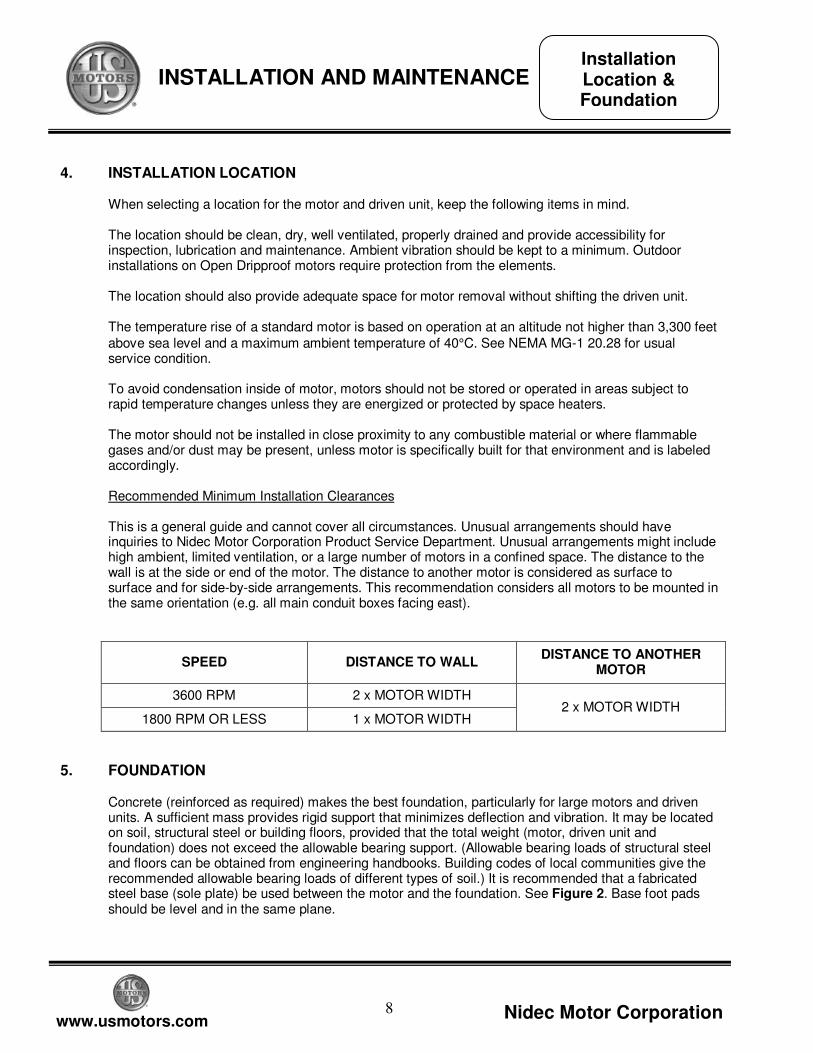
above sea level and a maximum ambient temperature of 40°C. See NEMA MG-1 20.28 for usual service condition. To avoid condensation inside of motor, motors should not be stored or operated in areas subject to rapid temperature changes unless they are energized or protected by space heaters. The motor should not be installed in close proximity to any combustible material or where flammable gases and/or dust may be present, unless motor is specifically built for that environment and is labeled accordingly. Recommended Minimum Installation Clearances This is a general guide and cannot cover all circumstances. Unusual arrangements should have inquiries to Nidec Motor Corporation Product Service Department. Unusual arrangements might include high ambient, limited ventilation, or a large number of motors in a confined space. The distance to the wall is at the side or end of the motor. The distance to another motor is considered as surface to surface and for side-by-side arrangements. This recommendation considers all motors to be mounted in the same orientation (e.g. all main conduit boxes facing east).
SPEED DISTANCE TO WALL DISTANCE TO ANOTHER
MOTOR
3600 RPM 2 x MOTOR WIDTH
1800 RPM OR LESS 1 x MOTOR WIDTH 2 x MOTOR WIDTH
5. FOUNDATION
Concrete (reinforced as required) makes the best foundation, particularly for large motors and driven units. A sufficient mass provides rigid support that minimizes deflection and vibration. It may be located on soil, structural steel or building floors, provided that the total weight (motor, driven unit and foundation) does not exceed the allowable bearing support. (Allowable bearing loads of structural steel and floors can be obtained from engineering handbooks. Building codes of local communities give the recommended allowable bearing loads of different types of soil.) It is recommended that a fabricated steel base (sole plate) be used between the motor and the foundation. See Figure 2. Base foot pads should be level and in the same plane.
Installation Location & Foundation
9
www.usmotors.com Nidec Motor Corporation
INSTALLATION AND MAINTENANCE
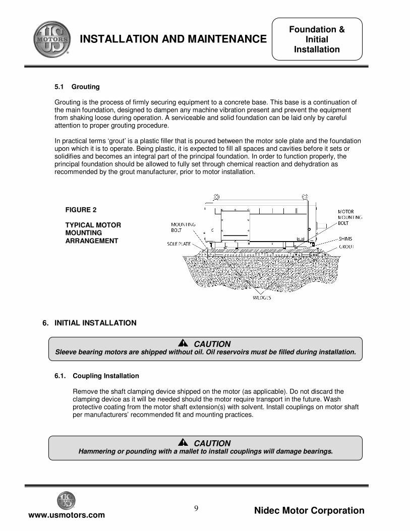
5.1 Grouting Grouting is the process of firmly securing equipment to a concrete base. This base is a continuation of the main foundation, designed to dampen any machine vibration present and prevent the equipment from shaking loose during operation. A serviceable and solid foundation can be laid only by careful attention to proper grouting procedure. In practical terms ‘grout’ is a plastic filler that is poured between the motor sole plate and the foundation upon which it is to operate. Being plastic, it is expected to fill all spaces and cavities before it sets or solidifies and becomes an integral part of the principal foundation. In order to function properly, the principal foundation should be allowed to fully set through chemical reaction and dehydration as recommended by the grout manufacturer, prior to motor installation.
6. INITIAL INSTALLATION
6.1. Coupling Installation
Remove the shaft clamping device shipped on the motor (as applicable). Do not discard the clamping device as it will be needed should the motor require transport in the future. Wash protective coating from the motor shaft extension(s) with solvent. Install couplings on motor shaft per manufacturers’ recommended fit and mounting practices.
FIGURE 2 TYPICAL MOTOR MOUNTING ARRANGEMENT
Hammering or pounding with a mallet to install couplings will damage bearings.
CAUTION
!
Foundation & Initial
Installation
Sleeve bearing motors are shipped without oil. Oil reservoirs must be filled during installation.
CAUTION
!
10
www.usmotors.com Nidec Motor Corporation
INSTALLATION AND MAINTENANCE
6.2 Rough Alignment
Inspect sole plate mounting pads and bottom of motor feet for dirt or irregularities that would prevent proper seating. Position and shim the motor such that the coupling hubs are aligned within 1/32 inch and the motor shaft is level. The motor shaft must be slightly lower than the driven shaft to allow for final adjustment shims. Shims and support mounting should provide support under the entire foot area.
6.3 Final Alignment
Accurate shaft alignment between motor and driven equipment is essential for trouble-free operation. Improper alignment can result in vibration, bearing overload and excessive shaft stresses. Flexible couplings may not adequately compensate for excessive misalignment. Whenever aligning a motor to driven equipment, keep the following rules in mind: - Do not place more than five shims in a shim pack under any one machine foot, as flexibility of
the shim pack will contribute to a soft foot condition. - After any corrective adjustment, tighten foot bolts securely and recheck alignment. - When making shim adjustments, change only one foot at a time. - Recheck alignment after the motor has been in service for approximately one week and
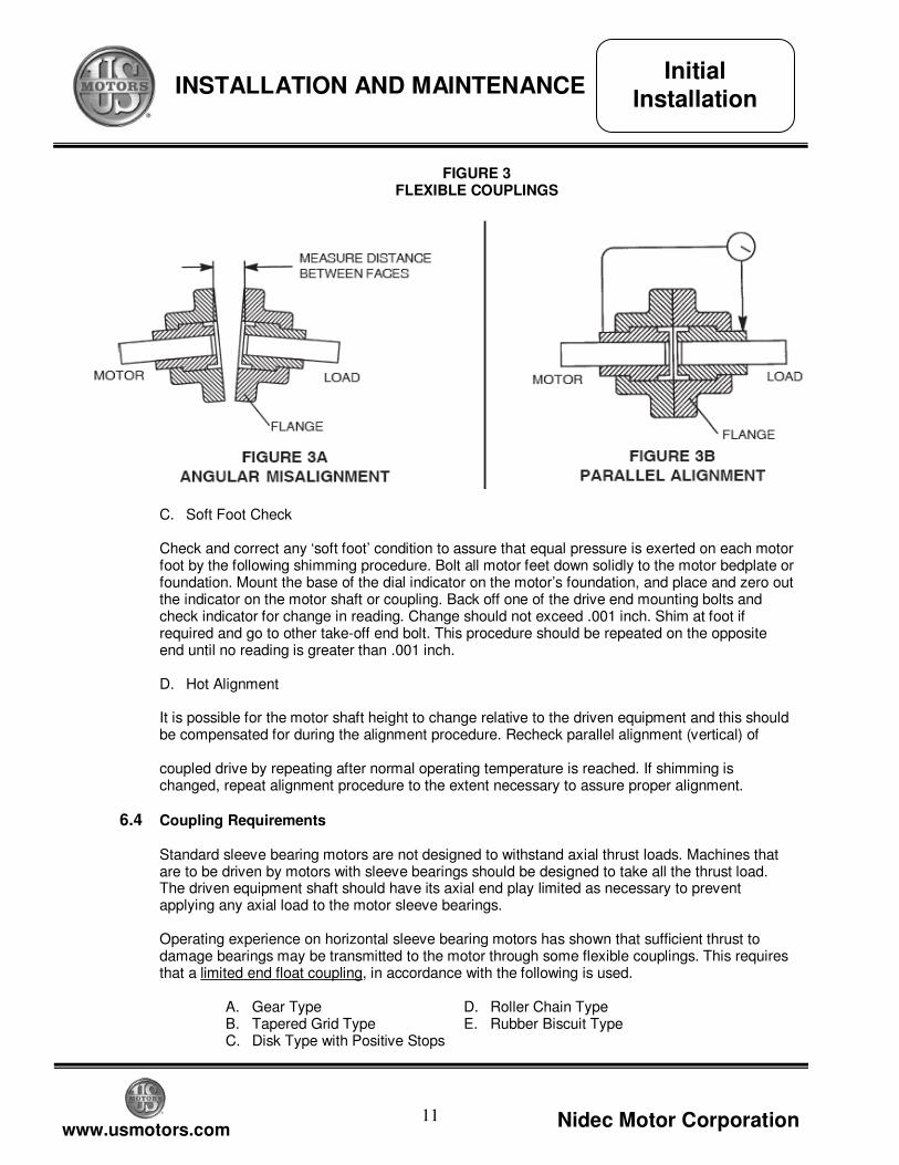
readjust as necessary. A. Angular Alignment (See Figure 3A) Check for angular misalignment of motor to driven unit shaft. (See Figure 3A). Measure distance between coupling hub faces (with feeler gauges) at four places equally spaced around the outside diameters. Position motor as necessary to be within the maximum allowable misalignment of .001 inch per foot of coupling radius. B. Parallel Alignment (See Figure 3B) Fasten a dial indicator onto one coupling hub with the indicator button on the cylindrical surface of the opposite coupling hub. Rotate shafts together and take readings at four points, 90° apart. Relocate motor until total indicator movement in full rotation does not exceed .002 inch. Transfer indicator to opposite hub and repeat the parallel alignment procedure. Recheck angular alignment as described in Step A.
For units with Sleeve Bearings: Sleeve bearing motors should be direct-coupled to the driven equipment. See coupling recommendations for recommended coupling type. Never use a pulley or sprocket as they transmit unacceptable radial loads to the motor bearings.
CAUTION
!
Initial Installation
11
www.usmotors.com Nidec Motor Corporation
INSTALLATION AND MAINTENANCE
FIGURE 3
FLEXIBLE COUPLINGS
C. Soft Foot Check Check and correct any ‘soft foot’ condition to assure that equal pressure is exerted on each motor foot by the following shimming procedure. Bolt all motor feet down solidly to the motor bedplate or foundation. Mount the base of the dial indicator on the motor’s foundation, and place and zero out the indicator on the motor shaft or coupling. Back off one of the drive end mounting bolts and check indicator for change in reading. Change should not exceed .001 inch. Shim at foot if required and go to other take-off end bolt. This procedure should be repeated on the opposite end until no reading is greater than .001 inch. D. Hot Alignment It is possible for the motor shaft height to change relative to the driven equipment and this should be compensated for during the alignment procedure. Recheck parallel alignment (vertical) of coupled drive by repeating after normal operating temperature is reached. If shimming is changed, repeat alignment procedure to the extent necessary to assure proper alignment.
6.4 Coupling Requirements Standard sleeve bearing motors are not designed to withstand axial thrust loads. Machines that are to be driven by motors with sleeve bearings should be designed to take all the thrust load. The driven equipment shaft should have its axial end play limited as necessary to prevent applying any axial load to the motor sleeve bearings. Operating experience on horizontal sleeve bearing motors has shown that sufficient thrust to damage bearings may be transmitted to the motor through some flexible couplings. This requires that a limited end float coupling, in accordance with the following is used.
A. Gear Type D. Roller Chain Type B. Tapered Grid Type E. Rubber Biscuit Type C. Disk Type with Positive Stops
Initial Installation
12
www.usmotors.com Nidec Motor Corporation
INSTALLATION AND MAINTENANCE
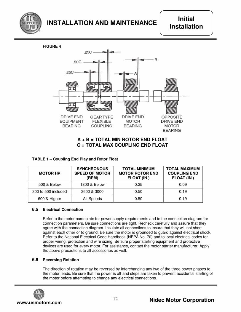
FIGURE 4
A + B = TOTAL MIN ROTOR END FLOAT C = TOTAL MAX COUPLING END FLOAT
TABLE 1 – Coupling End Play and Rotor Float
MOTOR HP SYNCHRONOUS
SPEED OF MOTOR (RPM)
TOTAL MINIMUM MOTOR ROTOR END
FLOAT (IN.)
TOTAL MAXIMUM COUPLING END
FLOAT (IN.)
500 & Below 1800 & Below 0.25 0.09
300 to 500 included 3600 & 3000 0.50 0.19
600 & Higher All Speeds 0.50 0.19
6.5 Electrical Connection Refer to the motor nameplate for power supply requirements and to the connection diagram for connection parameters. Be sure connections are tight. Recheck carefully and assure that they agree with the connection diagram. Insulate all connections to insure that they will not short against each other or to ground. Be sure the motor is grounded to guard against electrical shock. Refer to the National Electrical Code Handbook (NFPA No. 70) and to local electrical codes for proper wiring, protection and wire sizing. Be sure proper starting equipment and protective devices are used for every motor. For assistance, contact the motor starter manufacturer. Apply the above precautions to all accessories as well.
6.6 Reversing Rotation The direction of rotation may be reversed by interchanging any two of the three power phases to the motor leads. Be sure that the power is off and steps are taken to prevent accidental starting of the motor before attempting to change any electrical connections.
Initial Installation
13
www.usmotors.com Nidec Motor Corporation
INSTALLATION AND MAINTENANCE
6.7 Initial Start After installation is completed, but before motor is put in regular service, make an initial start as follows: A. Insure that motor and control device connections agree with wiring diagrams. B. Insure that voltage, phase and frequency of line circuit (power supply) agree with motor
nameplate.
C. Check insulation resistance according to Section 3 ‘Storage’, Part 3.3.
D. Check all foundation and base bolts to insure that they are tight.
E. If motor has been in storage, either before or after installation, refer to Section 3 ‘Storage’, Part 3.4.
F. Check for proper or desired rotation. See Part 6.6 of this section.
G. Insure that all protective devices are connected and are operating properly.
H. Check sleeve bearing housings to be certain that they have been filled to the ‘MAX’ level with
the correct lubricant recommended in the instruction manual and lubrication plate.
I. Run motor at minimum possible load long enough to be certain that no unusual condition develops. Listen and feel for excessive noise, vibration, clicking or pounding. If any are present, stop motor immediately. Investigate the cause and correct before putting motor into service. In the case of vibration, see Part 6.8 of this section.
Some motors have unidirectional ventilating fans. Running such a unit in reverse for any extended length of time will result in motor damage. On motors that are unidirectional, the direction of rotation is noted by an arrow mounted on the motor and by a warning plate mounted near the main nameplate. To determine direction of rotation for which leads are connected, apply power momentarily and observe rotation. Motor should be uncoupled from driven equipment to insure driven equipment is not damaged by reverse rotation. Motor coupling may require removal or support if motor is operated uncoupled from driven equipment.
CAUTION
!
Repeated trial starts can overheat the motor (particularly for across-the-line starting) or the external starting equipment. If repeated trial starts are made, allow sufficient time between starts to permit heat to be dissipated from windings and controls to prevent overheating. Refer to Starting Duty Nameplate (if supplied) and NEMA MG1-12.54, MG1-20.11 and MG1-20.12 for allowable starting frequency and load inertia (WR2).
CAUTION
!
Initial Installation
14
www.usmotors.com Nidec Motor Corporation
INSTALLATION AND MAINTENANCE
J. When checks are satisfactory to this point, increase the load slowly up to rated load and
check unit for satisfactory operation.
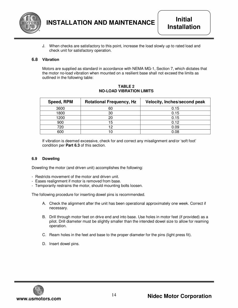
6.8 Vibration Motors are supplied as standard in accordance with NEMA MG-1, Section 7, which dictates that the motor no-load vibration when mounted on a resilient base shall not exceed the limits as outlined in the following table:
TABLE 2 NO-LOAD VIBRATION LIMITS
Speed, RPM Rotational Frequency, Hz Velocity, Inches/second peak
3600 60 0.15 1800 30 0.15 1200 20 0.15 900 15 0.12 720 12 0.09 600 10 0.08
If vibration is deemed excessive, check for and correct any misalignment and/or ‘soft foot’ condition per Part 6.3 of this section.
6.9 Doweling
Doweling the motor (and driven unit) accomplishes the following: - Restricts movement of the motor and driven unit. - Eases realignment if motor is removed from base. - Temporarily restrains the motor, should mounting bolts loosen. The following procedure for inserting dowel pins is recommended.
A. Check the alignment after the unit has been operational approximately one week. Correct if necessary.
B. Drill through motor feet on drive end and into base. Use holes in motor feet (if provided) as a
pilot. Drill diameter must be slightly smaller than the intended dowel size to allow for reaming operation.
C. Ream holes in the feet and base to the proper diameter for the pins (light press fit). D. Insert dowel pins.
Initial Installation
15
www.usmotors.com Nidec Motor Corporation
INSTALLATION AND MAINTENANCE
7. ROUTINE MAINTENANCE
Start the motor in accordance with the standard instructions for the starting equipment used. Connected load should be reduced to the minimum, particularly for reduced voltage starting and/or high inertia connected loads, until the unit has reached full speed. 7.1 General Maintenance
Routine maintenance prevents costly shutdown and repairs. Major elements of a controlled maintenance program include: A. Trained personnel who KNOW the work. B. Systematic records, which contain at least the following:
(1) Complete nameplate data. (2) Prints (wiring diagrams, certified outline dimensions). (3) Alignment data (departures from perfect alignment, allowance for temperature). (4) Winding resistance and temperature. (5) Results of regular inspection, including vibration and bearing temperature data as
applicable. (6) Documentation of any repairs. (7) Lubrication data (method of application, type of lubricant used, maintenance cycle by
location). 7.2 Inspection & Cleaning
Stop the motor before cleaning. Clean the motor, inside and outside, regularly. The frequency depends upon actual conditions existing around the motor. Use the following procedures, as they apply: A. Wipe any contaminants from external surfaces of the motor. B. Filters in weather-protected tophats should be removed and cleaned per filter manufacturer’s
recommendations. To remove filters, remove end cover and rotate latch. Slide filter out of tophat assembly.
C. Remove dirt, dust or debris from ventilating air inlets. Use compressed air as necessary.
Never allow dirt to accumulate near air inlets. Never operate motor with the air passages blocked or restricted.
D. Clean motors internally by vacuuming or blowing with clean, dry compressed air. Generally a
pressure not exceeding 30 PSI is recommended. When dirt and dust are solidly packed, or windings are coated with oil or greasy grime, disassemble the motor and clean with solvent. Use only high-flash naphtha, mineral spirits, or Stoddard solvent. Wipe with solvent-dampened cloth, or use suitable soft bristle brush. DO NOT SOAK. Oven dry (150 - 175° F) solvent-cleaned windings thoroughly before assembly.
Assure against accidental starting of motor. Disconnect and lock out power before working
on equipment. See ‘Safety’ section.
DANGER
!
Routine Maintenance
16
www.usmotors.com Nidec Motor Corporation
INSTALLATION AND MAINTENANCE
E. After cleaning and drying the windings, check the insulation resistance. Refer to Section 3.3.
7.3 Bearings
Proper care will help prolong the life of the motor bearings. Ensure the alignment and lubrication are properly maintained.
7.4 Bearing Insulation To prevent bearing damage from circulating current, one or both bearings may be insulated. Note that not all motors are equipped with insulated bearings. During overhauls, an insulation resistance check may be performed to assure that the insulation has not been weakened or damaged. Resistance can be checked by the use of an ohmmeter. On sleeve bearing units with both bearings insulated, the bearing grounding strap must be disconnected before testing.
7.5 Bearing Lubrication
A. Relubrication
If motor is being taken out of storage, refer to ‘Storage’ - Section 3.4 for preparation instructions. Select a premium-quality turbine oil which is fully inhibited against rust and oxidation. Refer to Table 3 for recommendations. Oil Pour Point must be below the minimum starting temperature unless sump heaters are used. Oil Viscosity Index must be at least 90.
Add oil to the bearing at the oil fill hole located at the top of each bearing housing. Oil level should be between the ‘Maximum’ and ‘Minimum’ lines located on the housing sight gauge windows. Also fill constant level oilers, if supplied. Refer to motor nameplate for approximate quantity of oil required.
Assure against accidental starting of motor. Disconnect and lock out power before working
on equipment. See ‘Safety’ section.
DANGER
!
Oil ‘Pour Point’ temperature must be below the minimum starting air temperature to ensure
adequate bearing lubrication at startup. If this cannot be achieved by oil selection alone then sump heaters should be specified and used to preheat the oil.
CAUTION
!
Routine Maintenance
When using compressed air, always use proper eye protection to prevent accidental injury.
CAUTION
!
17
www.usmotors.com Nidec Motor Corporation
INSTALLATION AND MAINTENANCE
7.6 Bearing Replacement
A. Disassembly
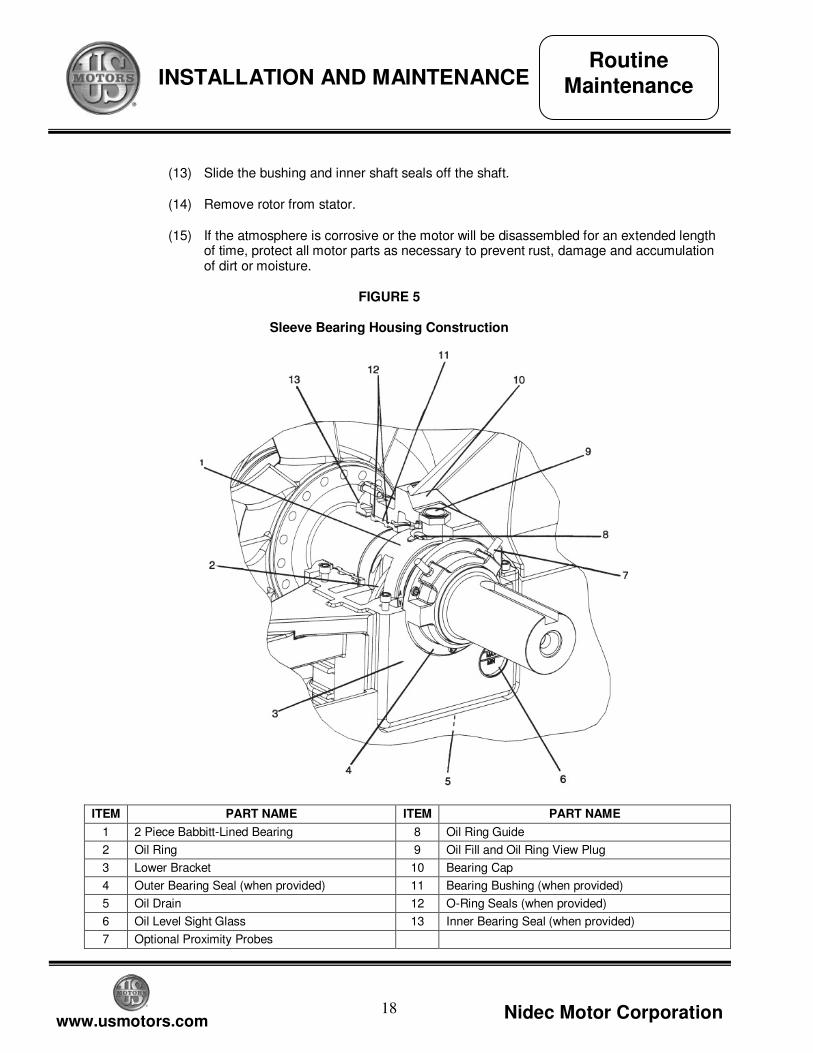
See Figure 5 for sleeve bearing housing cross-section.
(1) Disconnect power and assure against accidental starting of motor
(2) Unbolt and remove end grills or shrouding.
(3) Remove screws from inner shaft seals
(4) Unbolt outer shaft seal, cover plate (opposite shaft end) and remove. Bearing caps are not interchangeable and have been identified to allow installation on the same bracket from which they are removed.
(5) Remove all thermostats, probes, thermocouples, etc. from bearings and brackets.
(6) Disconnect vent tube from inner seal. Remove bolts that hold inner seal. Unbolt and remove bearing caps.
(7) Unbolt and remove upper halves of bearings.
(8) Remove bearing temperature detector probes (if provided).
(9) Raise the motor shaft approximately 1/32 inch. The take-off end of the shaft can be lifted by placing a sling directly around the shaft extension. The end of the shaft opposite the take-off end can be lifted by threading a bolt or eyebolt into the threaded hole in the end of the shaft and placing the sling around it. Once the shaft is raised, rotate the lower halves of the bearing cartridges out from under the shaft.
(10) Remove the oil rings.
(11) Drain oil from bracket reservoirs.
(12) Remove bolts holding brackets to frame and remove brackets.
Ensure against accidental starting of motor. Disconnect and lock out power before working on
equipment. See ‘Safety’ section.
DANGER
!
Bearing shells are manufactured as matched pairs. Do not mix bearing shell halves.
NOTICE
Routine Maintenance
Raising the shaft beyond the free movement of the rotor may damage the shaft, rotor or stator.
CAUTION
!
18
www.usmotors.com Nidec Motor Corporation
INSTALLATION AND MAINTENANCE
(13) Slide the bushing and inner shaft seals off the shaft.
(14) Remove rotor from stator.
(15) If the atmosphere is corrosive or the motor will be disassembled for an extended length of time, protect all motor parts as necessary to prevent rust, damage and accumulation of dirt or moisture.
FIGURE 5
Sleeve Bearing Housing Construction
ITEM PART NAME ITEM PART NAME
1 2 Piece Babbitt-Lined Bearing 8 Oil Ring Guide
2 Oil Ring 9 Oil Fill and Oil Ring View Plug
3 Lower Bracket 10 Bearing Cap
4 Outer Bearing Seal (when provided) 11 Bearing Bushing (when provided)
5 Oil Drain 12 O-Ring Seals (when provided)
6 Oil Level Sight Glass 13 Inner Bearing Seal (when provided)
7 Optional Proximity Probes
Routine Maintenance
19
www.usmotors.com Nidec Motor Corporation
INSTALLATION AND MAINTENANCE
B. Reassembly
(1) Ensure all parts in the bearing housing are clean and not damaged.
(2) Ensure that the shaft journals are clean and there are no gouges or corrosion present.
(3) Inspect the bearing babbitt bore surface for any unusual or excessive wear patterns, imbedded dirt or distinct scratches. Bearings so damaged should be repaired or replaced.
(4) Inspect o-rings for any damaged area. O-rings that are damaged must be replaced.
(5) To reassemble the motor, reverse procedure for disassembly. Coat o-ring seals with silicone grease prior to assembling bushing on shaft. Coat the shaft bearing journals, bearing surfaces and spherical seat surfaces with oil (see Table 3 for proper oil) prior to assembly. When installing the bearing cap, coat it’s mating surface and the mating surface of the bracket with Permatex #2 or an equivalent non-hardening sealant.
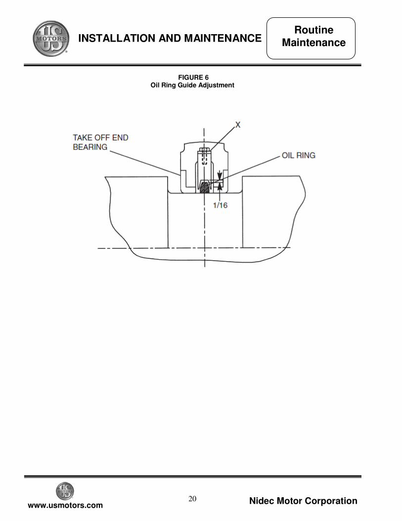
(6) Install the oil ring guides onto the replacement bearing and adjust by bending at ‘X’ to obtain dimension shown in Figure 6.
(7) A minimum gap of 0.004” (verified by feeler gauge) is to be provided all around between the seals and shaft to prevent rub. Check clearance and reposition seals as required.
(8) When motor is fully assembled and housings have been filled with proper oil (see Table 3) turn the shaft by hand and check for free rotation. Oil rings should be viewed at this time to check for free rotation.
(9) Touch up any scratched or chipped paint to protect motor surfaces.
Cleanliness is critical in assembling sleeve bearing motors. Make every effort to prevent
contamination from getting into the bearing housing.
NOTICE
Routine Maintenance
20
www.usmotors.com Nidec Motor Corporation
INSTALLATION AND MAINTENANCE
FIGURE 6
Oil Ring Guide Adjustment
Routine Maintenance
21
www.usmotors.com Nidec Motor Corporation
INSTALLATION AND MAINTENANCE
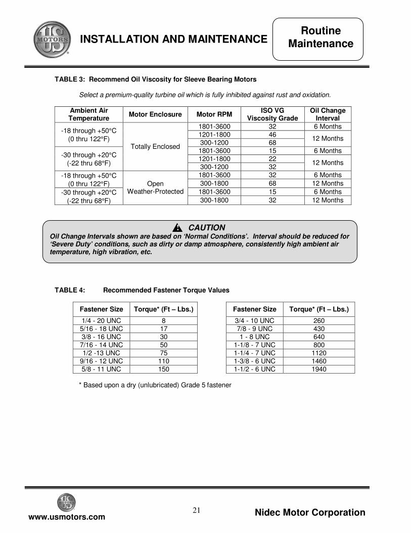
TABLE 3: Recommend Oil Viscosity for Sleeve Bearing Motors
Select a premium-quality turbine oil which is fully inhibited against rust and oxidation.
Ambient Air Temperature
Motor Enclosure Motor RPM ISO VG
Viscosity Grade Oil Change
Interval
1801-3600 32 6 Months 1201-1800 46
-18 through +50°C
(0 thru 122°F) 300-1200 68
12 Months
1801-3600 15 6 Months 1201-1800 22
-30 through +20°C
(-22 thru 68°F)
Totally Enclosed
300-1200 32 12 Months
1801-3600 32 6 Months -18 through +50°C
(0 thru 122°F) 300-1800 68 12 Months
1801-3600 15 6 Months -30 through +20°C
(-22 thru 68°F)
Open Weather-Protected
300-1800 32 12 Months
TABLE 4: Recommended Fastener Torque Values
Fastener Size Torque* (Ft – Lbs.) Fastener Size Torque* (Ft – Lbs.)
1/4 - 20 UNC 8 3/4 - 10 UNC 260 5/16 - 18 UNC 17 7/8 - 9 UNC 430 3/8 - 16 UNC 30 1 - 8 UNC 640 7/16 - 14 UNC 50 1-1/8 - 7 UNC 800 1/2 -13 UNC 75 1-1/4 - 7 UNC 1120
9/16 - 12 UNC 110 1-3/8 - 6 UNC 1460 5/8 - 11 UNC 150 1-1/2 - 6 UNC 1940
* Based upon a dry (unlubricated) Grade 5 fastener
Oil Change Intervals shown are based on ‘Normal Conditions’. Interval should be reduced for ‘Severe Duty’ conditions, such as dirty or damp atmosphere, consistently high ambient air temperature, high vibration, etc.
CAUTION
!
Routine Maintenance
22
www.usmotors.com Nidec Motor Corporation
INSTALLATION AND MAINTENANCE
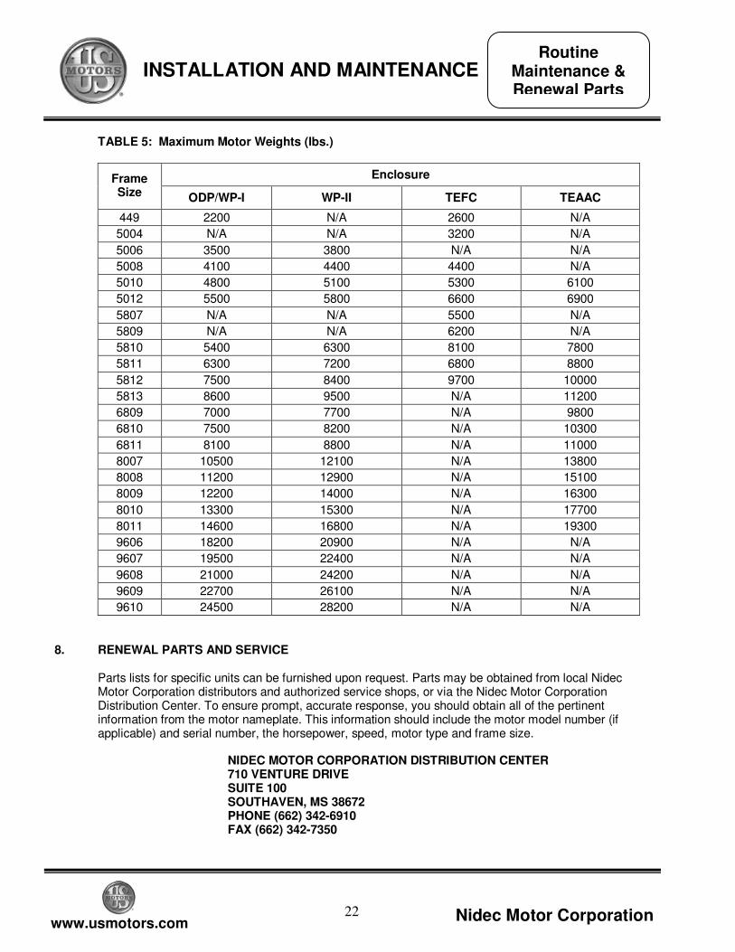
TABLE 5: Maximum Motor Weights (lbs.)
Enclosure Frame Size ODP/WP-I WP-II TEFC TEAAC
449 2200 N/A 2600 N/A
5004 N/A N/A 3200 N/A
5006 3500 3800 N/A N/A
5008 4100 4400 4400 N/A
5010 4800 5100 5300 6100
5012 5500 5800 6600 6900
5807 N/A N/A 5500 N/A
5809 N/A N/A 6200 N/A
5810 5400 6300 8100 7800
5811 6300 7200 6800 8800
5812 7500 8400 9700 10000
5813 8600 9500 N/A 11200
6809 7000 7700 N/A 9800
6810 7500 8200 N/A 10300
6811 8100 8800 N/A 11000
8007 10500 12100 N/A 13800
8008 11200 12900 N/A 15100
8009 12200 14000 N/A 16300
8010 13300 15300 N/A 17700
8011 14600 16800 N/A 19300
9606 18200 20900 N/A N/A
9607 19500 22400 N/A N/A
9608 21000 24200 N/A N/A
9609 22700 26100 N/A N/A
9610 24500 28200 N/A N/A
8. RENEWAL PARTS AND SERVICE
Parts lists for specific units can be furnished upon request. Parts may be obtained from local Nidec Motor Corporation distributors and authorized service shops, or via the Nidec Motor Corporation Distribution Center. To ensure prompt, accurate response, you should obtain all of the pertinent information from the motor nameplate. This information should include the motor model number (if applicable) and serial number, the horsepower, speed, motor type and frame size.
NIDEC MOTOR CORPORATION DISTRIBUTION CENTER 710 VENTURE DRIVE SUITE 100 SOUTHAVEN, MS 38672 PHONE (662) 342-6910 FAX (662) 342-7350
Routine Maintenance & Renewal Parts
23
www.usmotors.com Nidec Motor Corporation
INSTALLATION AND MAINTENANCE
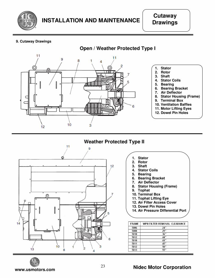
9. Cutaway Drawings
Cutaway Drawings
1. Stator 2. Rotor 3. Shaft 4. Stator Coils 5. Bearing 6. Bearing Bracket 7. Air Deflector 8. Stator Housing (Frame) 9. Terminal Box 10. Ventilation Baffles 11. Motor Lifting Eyes 12. Dowel Pin Holes
Open / Weather Protected Type I
Weather Protected Type II
1. Stator 2. Rotor 3. Shaft 4. Stator Coils 5. Bearing 6. Bearing Bracket 7. Air Deflector 8. Stator Housing (Frame) 9. Tophat 10. Terminal Box 11. Tophat Lifting Eye 12. Air Filter Access Cover 13. Dowel Pin Holes 14. Air Pressure Differential Port
24
www.usmotors.com Nidec Motor Corporation
INSTALLATION AND MAINTENANCE
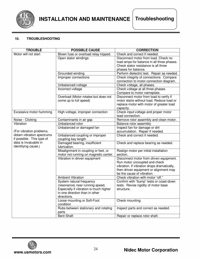
10. TROUBLESHOOTING
TROUBLE POSSIBLE CAUSE CORRECTION
Blown fuse or overload relay tripped. Check and correct if needed. Open stator windings Disconnect motor from load. Check no
load amps for balance in all three phases. Check stator resistance is all three phases for balance.
Grounded winding Perform dielectric test. Repair as needed. Improper connections Check integrity of connections. Compare
connection to motor connection diagram. Unbalanced voltage Check voltage, all phases. Incorrect voltage Check voltage at all three phases.
Compare to motor nameplate.
Motor will not start
Overload (Motor rotates but does not come up to full speed)
Disconnect motor from load to verify if motor starts without load. Reduce load or replace motor with motor of greater load capacity.
Excessive motor humming High voltage, improper connection Check input voltage and proper motor lead connection.
Noise - Clicking Contaminants in air gap Remove rotor assembly and clean motor. Unbalanced rotor Balance rotor assembly Unbalanced or damaged fan Inspect fan for damage or dirt
accumulation. Repair if needed. Unbalanced coupling or improper coupling key length
Check and correct if needed.
Damaged bearing, insufficient lubrication.
Check and replace bearing as needed.
Misalignment in coupling or feet, or motor not running on magnetic center.
Realign motor per initial installation section.
Vibration in driven equipment Disconnect motor from driven equipment. Run motor uncoupled and check vibration. If vibration drops dramatically, then driven equipment or alignment may be the cause of vibration.
Ambient Vibration Check vibration with motor “off.” System natural frequency (resonance) near running speed, Especially if vibration is much higher in one direction than in other directions.
Confirm with “bump” tests or coast-down tests. Revise rigidity of motor base structure.
Loose mounting or Soft-Foot condition
Check mounting.
Rubs between stationary and rotating parts
Inspect parts and correct as needed.
Vibration (For vibration problems, obtain vibration spectrums if possible. This type of data is invaluable in identifying cause.)
Bent Shaft Repair or replace rotor shaft.
Troubleshooting
25
www.usmotors.com Nidec Motor Corporation
INSTALLATION AND MAINTENANCE
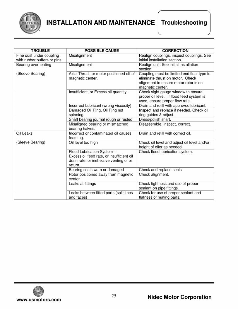
TROUBLE POSSIBLE CAUSE CORRECTION
Fine dust under coupling with rubber buffers or pins
Misalignment Realign couplings, inspect couplings. See initial installation section.
Misalignment Realign unit. See initial installation section.
Axial Thrust, or motor positioned off of magnetic center.
Coupling must be limited end float type to eliminate thrust on motor. Check alignment to ensure motor rotor is on magnetic center.
Insufficient, or Excess oil quantity. Check sight gauge window to ensure proper oil level. If flood feed system is used, ensure proper flow rate.
Incorrect Lubricant (wrong viscosity) Drain and refill with approved lubricant. Damaged Oil Ring, Oil Ring not spinning
Inspect and replace if needed. Check oil ring guides & adjust.
Shaft bearing journal rough or rusted Dress/polish shaft.
Bearing overheating (Sleeve Bearing)
Misaligned bearing or mismatched bearing halves.
Disassemble, inspect, correct.
Incorrect or contaminated oil causes foaming.
Drain and refill with correct oil.
Oil level too high Check oil level and adjust oil level and/or height of oiler as needed.
Flood Lubrication System – Excess oil feed rate, or insufficient oil drain rate, or ineffective venting of oil return.
Check flood lubrication system.
Bearing seals worn or damaged Check and replace seals Rotor positioned away from magnetic center
Check alignment.
Leaks at fittings Check tightness and use of proper sealant on pipe fittings.
Oil Leaks (Sleeve Bearing)
Leaks between fitted parts (split lines and faces)
Check for use of proper sealant and flatness of mating parts.
Troubleshooting
26
www.usmotors.com Nidec Motor Corporation
INSTALLATION AND MAINTENANCE
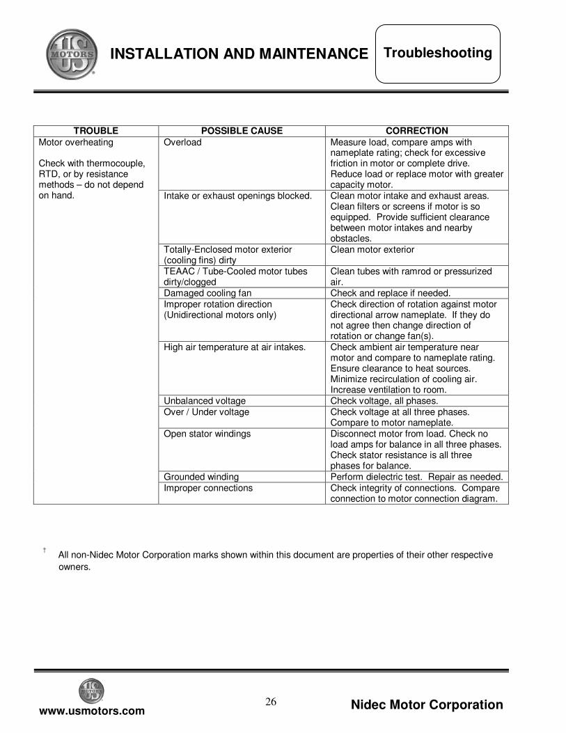
TROUBLE POSSIBLE CAUSE CORRECTION
Overload Measure load, compare amps with nameplate rating; check for excessive friction in motor or complete drive. Reduce load or replace motor with greater capacity motor.
Intake or exhaust openings blocked. Clean motor intake and exhaust areas. Clean filters or screens if motor is so equipped. Provide sufficient clearance between motor intakes and nearby obstacles.
Totally-Enclosed motor exterior (cooling fins) dirty
Clean motor exterior
TEAAC / Tube-Cooled motor tubes dirty/clogged
Clean tubes with ramrod or pressurized air.
Damaged cooling fan Check and replace if needed. Improper rotation direction (Unidirectional motors only)
Check direction of rotation against motor directional arrow nameplate. If they do not agree then change direction of rotation or change fan(s).
High air temperature at air intakes. Check ambient air temperature near motor and compare to nameplate rating. Ensure clearance to heat sources. Minimize recirculation of cooling air. Increase ventilation to room.
Unbalanced voltage Check voltage, all phases. Over / Under voltage Check voltage at all three phases.
Compare to motor nameplate. Open stator windings Disconnect motor from load. Check no
load amps for balance in all three phases. Check stator resistance is all three phases for balance.
Grounded winding Perform dielectric test. Repair as needed.
Motor overheating Check with thermocouple, RTD, or by resistance methods – do not depend on hand.
Improper connections Check integrity of connections. Compare connection to motor connection diagram.
† All non-Nidec Motor Corporation marks shown within this document are properties of their other respective
owners.
Troubleshooting
27
www.usmotors.com Nidec Motor Corporation
INSTALLATION AND MAINTENANCE
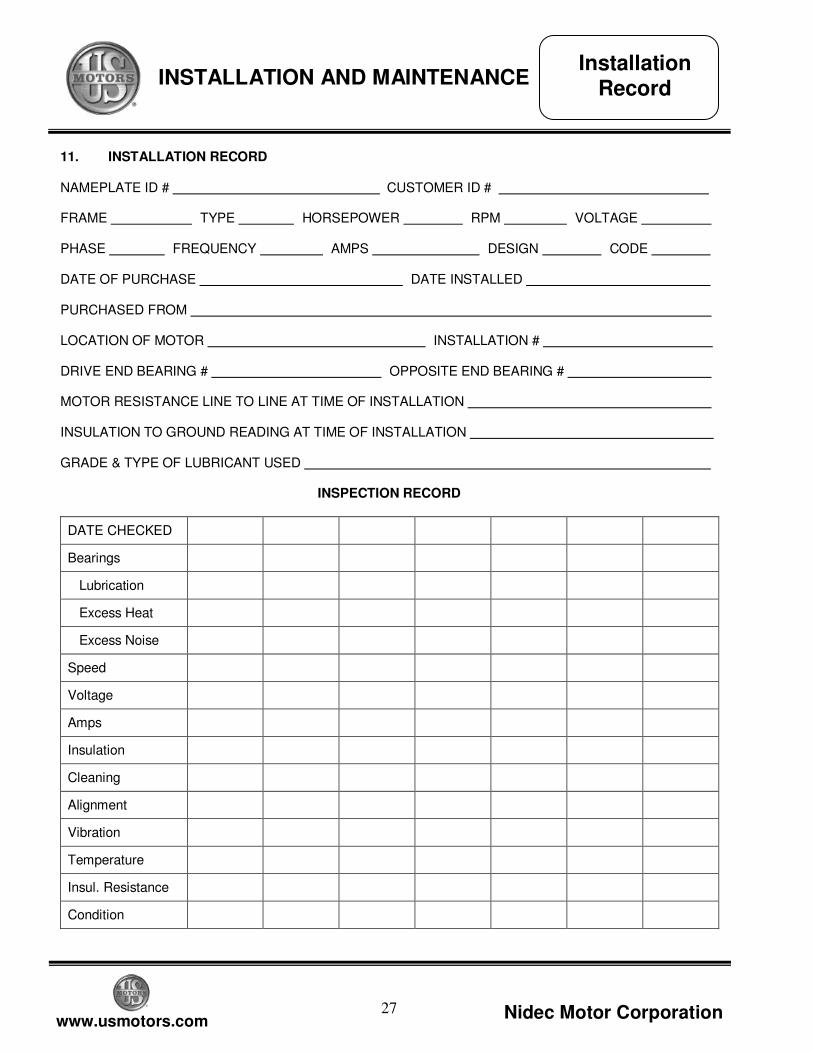
11. INSTALLATION RECORD NAMEPLATE ID # CUSTOMER ID # _ FRAME - TYPE - HORSEPOWER - RPM - VOLTAGE - PHASE - FREQUENCY - AMPS - DESIGN - CODE - DATE OF PURCHASE - DATE INSTALLED - PURCHASED FROM - LOCATION OF MOTOR - INSTALLATION # - DRIVE END BEARING # - OPPOSITE END BEARING # - MOTOR RESISTANCE LINE TO LINE AT TIME OF INSTALLATION - INSULATION TO GROUND READING AT TIME OF INSTALLATION - GRADE & TYPE OF LUBRICANT USED -
INSPECTION RECORD
DATE CHECKED
Bearings
Lubrication
Excess Heat
Excess Noise
Speed
Voltage
Amps
Insulation
Cleaning
Alignment
Vibration
Temperature
Insul. Resistance
Condition
Installation Record
28
www.usmotors.com Nidec Motor Corporation
INSTALLATION AND MAINTENANCE
†All marks shown within this document are properties of their respective owners. Nidec Motor Corporation, 2011, All Rights Reserved. U.S. MOTORS® is a registered trademark of Nidec Motor Corporation. Nidec Motor Corporation trademarks followed by the ® symbol are Registered with the U.S. Patent and Trademark Office. P/N 986240 Rev. 08/11 IN 234-244A
NIDEC MOTOR CORPORATION
8050 W. Florissant Avenue | St. Louis, MO 63136 Phone: 800-566-1418 | Fax: 314-595-8922
www.usmotors.com