Embed Size (px)
Citation preview

— M ED I U M VO LTAG E S ERV I CE
VD4GInstallation and operating instructions15 kV - 1250...3150 A - 25...40 kA
• Make sure that the rated performance of the apparatus is not exceeded during service.
• Make sure that the personnel are provided with this manual and all the information required for operating the apparatus correctly.
• Pay special attention to the information in the manual highlighted by the following symbol:
—For your safety!• Make sure that the installation room (space,
divisions and environment) is suitable for the electrical apparatus.
• Make sure that all the installation, putting into service and maintenance operations are carried out by skilled personnel with in-depth knowledge of the equipment.
• Check that all the installation, service and maintenance operations comply with the regulations and laws in force so as to ensure that the installations are constructed in accordance with the rules of good workmanship and safety in the work place.
• Strictly comply with the instructions in this manual.
Responsible behavior safeguards your own and others’ safety!Please contact the ABB Assistance Service for any further requirements.
ContentsFor your safety! 1 I. Foreword 2 II. Environmental protection program 2 1. Packing and transport 3 2. Checking on receipt 4 3. Storage 5 4. Handling 6 5. Description 7 6. Instructions for circuit-breaker switching 24 7. Installation 27 8. Putting into service 31 9. Maintenance 33 10. Application of the X-ray emission
Standards 37 11. Spare parts and accessories 38 12. Circuit diagrams 39 13. Overall dimensions 40 14. Quality of the products and environmental
protection 44

2 V D 4 G - INS TA L L ATI O N A N D O PER ATI N G I NS TR U C TI O NS
This publication contains the information required to install VD4G medium voltage circuit-breakers and put them into service.Please read the manual carefully to ensure that the product is used correctly.Similarly to all the apparatus we manufacture, VD4G circuit-breakers are designed for different installation configurations. They can therefore undergo further technical-construction modifications (at the customer’s request) so as to adapt them to special installation requirements.Consequently, the manual may not contain instructions concerning special customized configurations.This means that, besides this manual, it is always necessary to consult the latest technical documentation (circuit and wiring diagrams, layouts, assembly and installation drawings, any protection coordination studies, etc.), especially regarding any variants requested in relation to the standard configurations.Only use original spare parts for maintenance operations. Please also consult the technical catalog of the circuit-breaker and the spare parts catalog for further details.
ALL THE INSTALLATION, PUTTING INTO SERVICE, RUNNING AND MAINTENANCE OPERATIONS MUST BE CARRIED OUT BY SUITABLY QUALIFIED PERSONNEL WITH IN-DEPTH KNOWLEDGE OF THE APPARATUS.
—I. Foreword
—II. Environmental protection program
VD4G circuit-breakers are manufactured in accordance with ISO 14000 Standards (Guidelines for environmental management).The manufacturing processes are implemented in accordance with the environmental protection standards when it comes to reducing both energy consumption and the production of waste. All this is thanks to the environmental management system applied in the medium voltage apparatus manufacturing facility.

M ED I U M VO LTAG E PR O D U C TS 3
—1. Packing and transport
The circuit-breaker is shipped in special packing, in the open position and with the spring discharged.Each piece of apparatus is protected by a plastic cover to prevent water from infiltrating during the loading and unloading stages and to keep the dust off during storage.
A
B
3
4
21
5
Ur
4 V D 4 G - INS TA L L ATI O N A N D O PER ATI N G I NS TR U C TI O NS
BEFORE PROCEEDING WITH ANY OPERATION, ALWAYS MAKE SURE THAT THE SPRINGS OF THE OPERATING MECHANISM ARE DISCHARGED AND THAT THE APPARATUS IS IN THE OPEN POSITION.
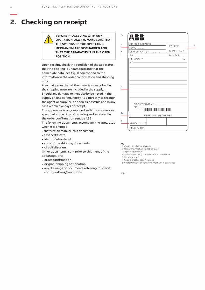
Upon receipt, check the condition of the apparatus, that the packing is undamaged and that the nameplate data (see fig. 1) correspond to the information in the order confirmation and shipping note.Also make sure that all the materials described in the shipping note are included in the supply.Should any damage or irregularity be noted in the supply on unpacking, notify ABB (directly or through the agent or supplier) as soon as possible and in any case within five days of receipt.The apparatus is only supplied with the accessories specified at the time of ordering and validated in the order confirmation sent by ABB.The following documents accompany the apparatus when it is shipped:• instruction manual (this document)• test certificate• identification label• copy of the shipping documents• circuit diagram.Other documents, sent prior to shipment of the apparatus, are:• order confirmation• original shipping notification• any drawings or documents referring to special
configurations/conditions.
—2. Checking on receipt
CIRCUIT-BREAKER IEC-IEEE
VD4G ... ... ... 62271-37-013CLASSIFICATION ... ... ...
SN ... ... ... PR. YEAR ......
CIRCUIT DIAGRAM ... ... ... ... FIG. ... ...
OPERATING MECHANISM
- MBO1 ... ... ... V
Made by ABB
M WEIGHT ... kVUr
Key A Circuit-breaker rating plate B Operating mechanism rating plate 1 Type of apparatus 2 Symbols denoting compliance with Standards 3 Serial number 4 Circuit-breaker specifications 5 Characteristics of operating mechanism auxiliaries
Fig. 1
M ED I U M VO LTAG E PR O D U C TS 5
When the apparatus must be stored for a certain period of time, our workshops can (on request) provide packing to suit the specified storage conditions.On receipt the apparatus must be carefully unpacked and checked as described in Checking on receipt (chap. 2).If the apparatus cannot be installed immediately, it must be re-packed in its original packing materials.Insert at least one standard packet of special hygroscopic substance inside the packing of each piece of apparatus.Should the original packing no longer be available and the apparatus cannot be installed immediately, it should be stored indoors in a well-ventilated, dry, dust-free, non-corrosive environment, well away from any easily flammable materials and at a temperature between – 5 °C and + 40 °C.Avoid accidental shocks or positions which stress the structure of the apparatus.
—3. Storage

3
C AB
1
2
3
6 V D 4 G - INS TA L L ATI O N A N D O PER ATI N G I NS TR U C TI O NS
Fig. 2
Fig. 2a Lifting support Fig. 3
Before proceeding with any operation, always make sure that the spring of the operating mechanism is discharged and that the apparatus is in the open position.Proceed as follows to lift and handle the circuit-breaker (fig. 2): • use suitable lifting equipment (1) (not supplied)
with ropes and safety hooks (2);• insert the hooks (2) into the supports (3) fixed to
the frame of the circuit-breaker and lift. Insert hooks (2) into holes in support (3), depending on the type of apparatus (see table);
• once the operation has terminated (and in any case before putting into service), release the lifting equipment (1) and remove the supports (3) from the frame.
When handling the apparatus, take great care to prevent the insulating parts and terminals of the circuit-breaker from being stressed.
DO NOT HANDLE THE APPARATUS BY INSERTING LIFTING DEVICES DIRECTLY UNDER IT. IF THIS TECHNIQUE IS UNAVOIDABLE, PLACE THE CIRCUIT-BREAKER ON A PALLET OR A STURDY SUPPORTING SURFACE (SEE FIG. 3).
IN ANY CASE, IT IS ALWAYS ADVISABLE TO LIFT THE APPARATUS BY MEANS OF THE SUPPORTS (3).
—4. Handling
Version Pole center distance
Rated current Hole
Fixed 150-210 mm 1,250 A A
Fixed 275 mm up to 3150 A A
Fixed 210 mm 2,000 A A
Fixed 275 mm 4,000 A C
Withdrawable 150 mm 1,250 A A
Withdrawable 210 mm 2,000 A B
Withdrawable 275 mm up to 3150 A C
Withdrawable 275 mm 4,000 A C
9
8
11
10
1
2
3
4
5
6
7
11
M ED I U M VO LTAG E PR O D U C TS 7
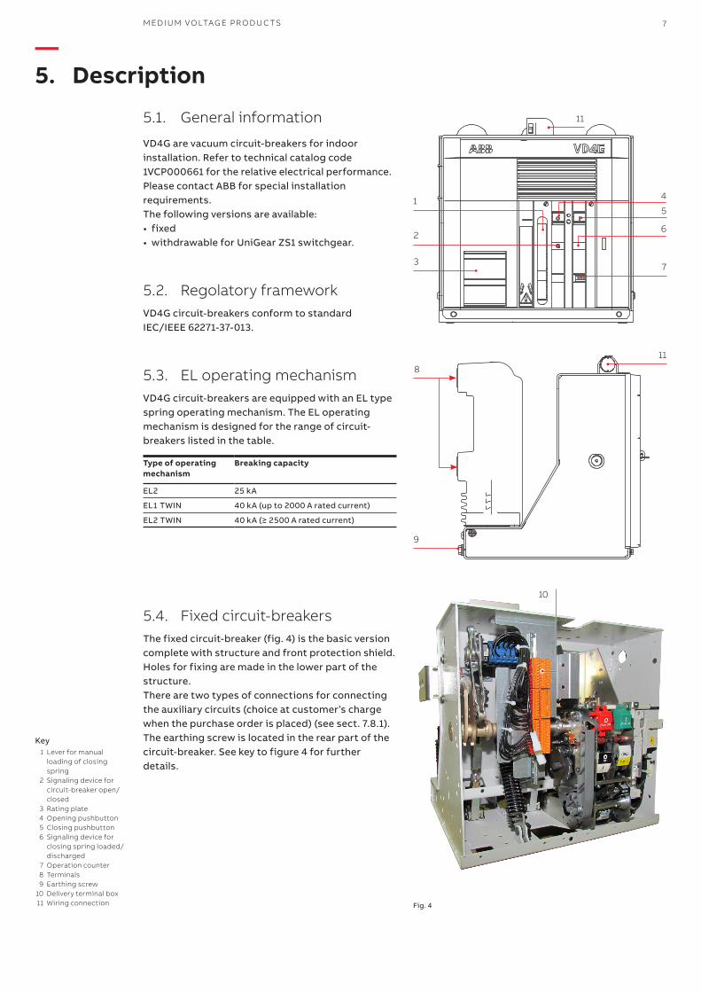
Key 1 Lever for manual
loading of closing spring
2 Signaling device for circuit-breaker open/closed
3 Rating plate 4 Opening pushbutton 5 Closing pushbutton 6 Signaling device for
closing spring loaded/discharged
7 Operation counter 8 Terminals 9 Earthing screw 10 Delivery terminal box 11 Wiring connection Fig. 4
5.1. General information
VD4G are vacuum circuit-breakers for indoor installation. Refer to technical catalog code 1VCP000661 for the relative electrical performance.Please contact ABB for special installation requirements.The following versions are available:• fixed• withdrawable for UniGear ZS1 switchgear.
5.2. Regolatory frameworkVD4G circuit-breakers conform to standard IEC/IEEE 62271-37-013.
5.3. EL operating mechanismVD4G circuit-breakers are equipped with an EL type spring operating mechanism. The EL operating mechanism is designed for the range of circuit-breakers listed in the table.
Type of operating mechanism
Breaking capacity
EL2 25 kA
EL1 TWIN 40 kA (up to 2000 A rated current)
EL2 TWIN 40 kA (≥ 2500 A rated current)
5.4. Fixed circuit-breakersThe fixed circuit-breaker (fig. 4) is the basic version complete with structure and front protection shield. Holes for fixing are made in the lower part of the structure. There are two types of connections for connecting the auxiliary circuits (choice at customer’s charge when the purchase order is placed) (see sect. 7.8.1). The earthing screw is located in the rear part of the circuit-breaker. See key to figure 4 for further details.
—5. Description
8 V D 4 G - INS TA L L ATI O N A N D O PER ATI N G I NS TR U C TI O NS
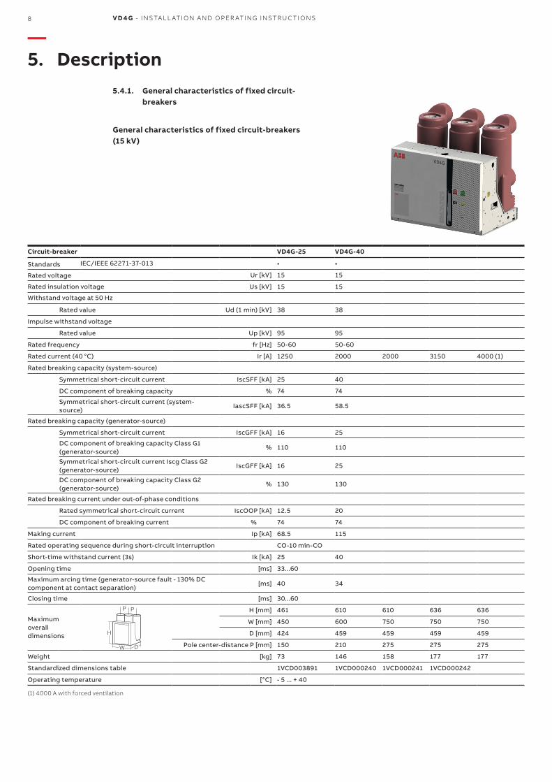
5.4.1. General characteristics of fixed circuit-breakers
General characteristics of fixed circuit-breakers (15 kV)
Circuit-breaker VD4G-25 VD4G-40
Standards IEC/IEEE 62271-37-013 • •
Rated voltage Ur [kV] 15 15
Rated insulation voltage Us [kV] 15 15
Withstand voltage at 50 Hz
Rated value Ud (1 min) [kV] 38 38
Impulse withstand voltage
Rated value Up [kV] 95 95
Rated frequency fr [Hz] 50-60 50-60
Rated current (40 °C) Ir [A] 1250 2000 2000 3150 4000 (1)
Rated breaking capacity (system-source)
Symmetrical short-circuit current IscSFF [kA] 25 40
DC component of breaking capacity % 74 74
Symmetrical short-circuit current (system-source)
IascSFF [kA] 36.5 58.5
Rated breaking capacity (generator-source)
Symmetrical short-circuit current IscGFF [kA] 16 25
DC component of breaking capacity Class G1 (generator-source)
% 110 110
Symmetrical short-circuit current Iscg Class G2 (generator-source)
IscGFF [kA] 16 25
DC component of breaking capacity Class G2 (generator-source)
% 130 130
Rated breaking current under out-of-phase conditions
Rated symmetrical short-circuit current IscOOP [kA] 12.5 20
DC component of breaking current % 74 74
Making current Ip [kA] 68.5 115
Rated operating sequence during short-circuit interruption CO-10 min-CO
Short-time withstand current (3s) Ik [kA] 25 40
Opening time [ms] 33...60
Maximum arcing time (generator-source fault - 130% DC component at contact separation)
[ms] 40 34
Closing time [ms] 30...60
Maximumoverall dimensions
H [mm] 461 610 610 636 636
W [mm] 450 600 750 750 750
D [mm] 424 459 459 459 459
Pole center-distance P [mm] 150 210 275 275 275
Weight [kg] 73 146 158 177 177
Standardized dimensions table 1VCD003891 1VCD000240 1VCD000241 1VCD000242
Operating temperature [°C] - 5 ... + 40
(1) 4000 A with forced ventilation
D
H
W
P P
—5. Description
M ED I U M VO LTAG E PR O D U C TS 9
(1) 4000 A with forced ventilation
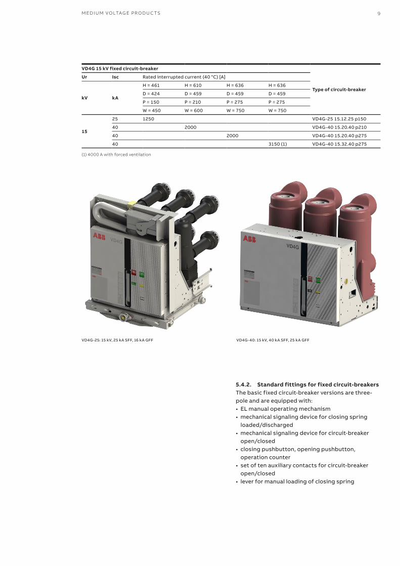
5.4.2. Standard fittings for fixed circuit-breakersThe basic fixed circuit-breaker versions are three-pole and are equipped with:• EL manual operating mechanism• mechanical signaling device for closing spring
loaded/discharged• mechanical signaling device for circuit-breaker
open/closed• closing pushbutton, opening pushbutton,
operation counter• set of ten auxiliary contacts for circuit-breaker
open/closed• lever for manual loading of closing spring
VD4G-40: 15 kV, 40 kA SFF, 25 kA GFFVD4G-25: 15 kV, 25 kA SFF, 16 kA GFF
VD4G 15 kV fixed circuit-breaker
Type of circuit-breaker
Ur Isc Rated interrupted current (40 °C) [A]
kV kA
H = 461 H = 610 H = 636 H = 636
D = 424 D = 459 D = 459 D = 459
P = 150 P = 210 P = 275 P = 275
W = 450 W = 600 W = 750 W = 750
15
25 1250 VD4G-25 15.12.25 p150
40 2000 VD4G-40 15.20.40 p210
40 2000 VD4G-40 15.20.40 p275
40 3150 (1) VD4G-40 15.32.40 p275
16
89
10
11
37
451
2
14
6
13
12
15
17
10 V D 4 G - INS TA L L ATI O N A N D O PER ATI N G I NS TR U C TI O NS
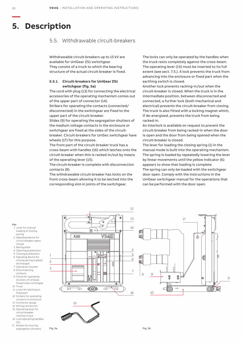
Withdrawable circuit-breakers up to 15 kV are available for UniGear ZS1 switchgear.They consist of a truck to which the bearing structure of the actual circuit-breaker is fixed.
5.5.1. Circuit-breakers for UniGear ZS1 switchgear (fig. 5a)
The cord with plug (13) for connecting the electrical accessories of the operating mechanism comes out of the upper part of connector (14). Strikers for operating the contacts (connected/disconnected) in the switchgear are fixed to the upper part of the circuit-breaker. Slides (9) for operating the segregation shutters of the medium voltage contacts in the enclosure or switchgear are fixed at the sides of the circuit-breaker. Circuit-breakers for UniSec switchgear have wheels (17) for this purpose.The front part of the circuit-breaker truck has a cross-beam with handles (16) which latches onto the circuit-breaker when this is racked-in/out by means of the operating lever (15). The circuit-breaker is complete with disconnection contacts (8).The withdrawable circuit-breaker has locks on the front cross-beam allowing it to be latched into the corresponding slot-in joints of the switchgear.
Key 1 Lever for manual
loading of closing spring
2 Signaling device for circuit-breaker open/closed
3 Rating plate 4 Opening pushbutton 5 Closing pushbutton 6 Signaling device for
closing spring loaded/discharged
7 Operation counter 8 Disconnecting
contacts 9 Chute for operating
shutters of UniGear, PowerCube switchgear
10 Truck 11 Locks for latching to
fixed part 12 Strikers for operating
contacts in enclosure 13 Connector (plug) 14 Wiring connection 15 Operating lever for
circuit-breaker racking-in/out
16 Lock operating handles (11)
17 Wheels for moving segregation shutters
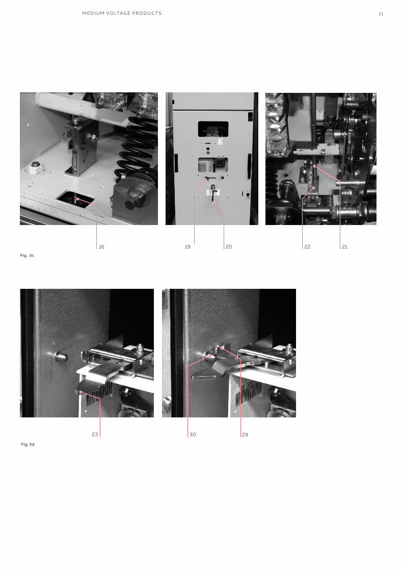
The locks can only be operated by the handles when the truck rests completely against the cross-beam.The operating lever (15) must be inserted to its full extent (see sect. 7.5.). A lock prevents the truck from advancing into the enclosure or fixed part when the earthing switch is closed. Another lock prevents racking-in/out when the circuit-breaker is closed. When the truck is in the intermediate position, between disconnected and connected, a further lock (both mechanical and electrical) prevents the circuit-breaker from closing. The truck is also fitted with a locking magnet which, if de-energized, prevents the truck from being racked-in. An interlock is available on request to prevent the circuit-breaker from being racked-in when the door is open and the door from being opened when the circuit-breaker is closed.The lever for loading the closing spring (1) in the manual mode is built into the operating mechanism. The spring is loaded by repeatedly lowering the lever by linear movements until the yellow indicator (6) appears to show that loading is complete.The spring can only be loaded with the switchgear door open. Comply with the instructions in the UniGear switchgear manual for the operations that can be performed with the door open.
—5. Description
5.5. Withdrawable circuit-breakers
Fig. 5a Fig. 5b
16 19 20 22 21
23 2930
M ED I U M VO LTAG E PR O D U C TS 11
Fig. 5c
Fig. 5d
12 V D 4 G - INS TA L L ATI O N A N D O PER ATI N G I NS TR U C TI O NS
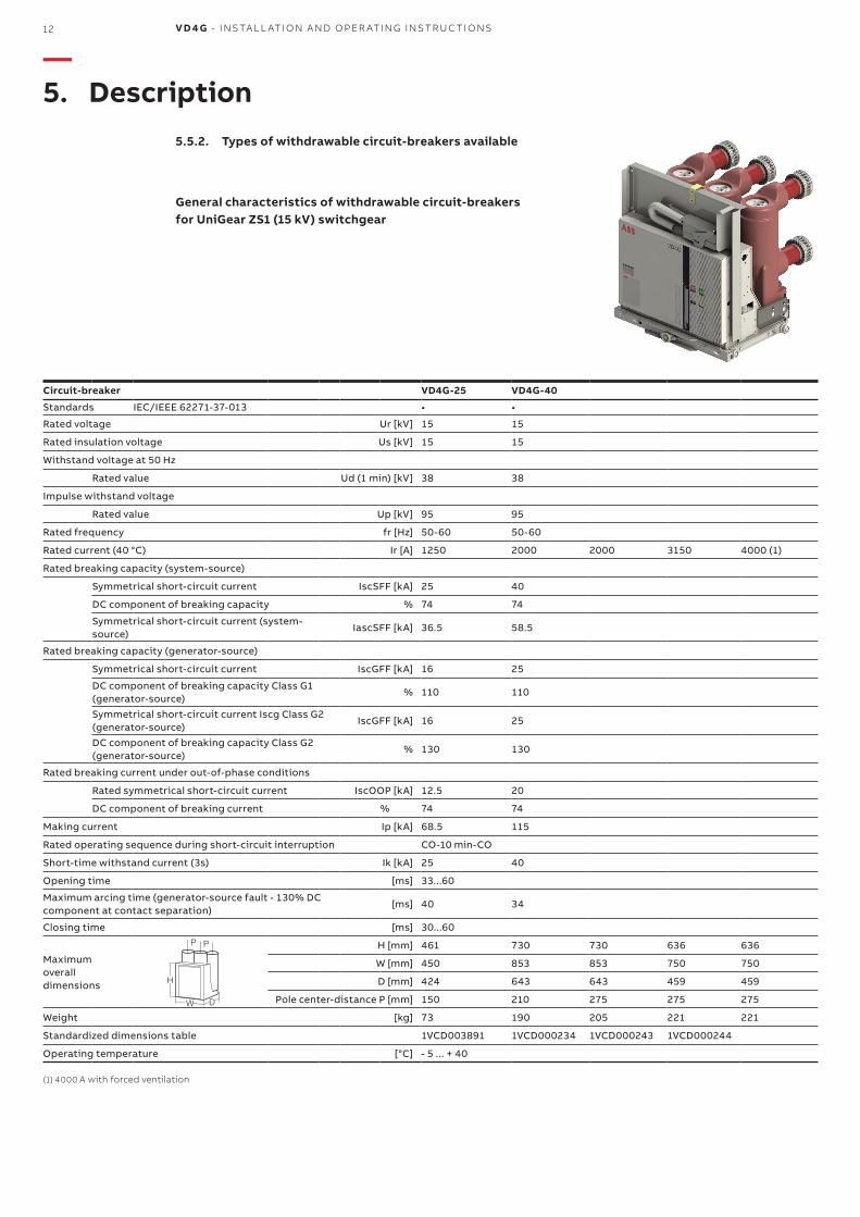
Circuit-breaker VD4G-25 VD4G-40
Standards IEC/IEEE 62271-37-013 • •
Rated voltage Ur [kV] 15 15
Rated insulation voltage Us [kV] 15 15
Withstand voltage at 50 Hz
Rated value Ud (1 min) [kV] 38 38
Impulse withstand voltage
Rated value Up [kV] 95 95
Rated frequency fr [Hz] 50-60 50-60
Rated current (40 °C) Ir [A] 1250 2000 2000 3150 4000 (1)
Rated breaking capacity (system-source)
Symmetrical short-circuit current IscSFF [kA] 25 40
DC component of breaking capacity % 74 74
Symmetrical short-circuit current (system-source)
IascSFF [kA] 36.5 58.5
Rated breaking capacity (generator-source)
Symmetrical short-circuit current IscGFF [kA] 16 25
DC component of breaking capacity Class G1 (generator-source)
% 110 110
Symmetrical short-circuit current Iscg Class G2 (generator-source)
IscGFF [kA] 16 25
DC component of breaking capacity Class G2 (generator-source)
% 130 130
Rated breaking current under out-of-phase conditions
Rated symmetrical short-circuit current IscOOP [kA] 12.5 20
DC component of breaking current % 74 74
Making current Ip [kA] 68.5 115
Rated operating sequence during short-circuit interruption CO-10 min-CO
Short-time withstand current (3s) Ik [kA] 25 40
Opening time [ms] 33...60
Maximum arcing time (generator-source fault - 130% DC component at contact separation)
[ms] 40 34
Closing time [ms] 30...60
Maximum overall dimensions
H [mm] 461 730 730 636 636
W [mm] 450 853 853 750 750
D [mm] 424 643 643 459 459
Pole center-distance P [mm] 150 210 275 275 275
Weight [kg] 73 190 205 221 221
Standardized dimensions table 1VCD003891 1VCD000234 1VCD000243 1VCD000244
Operating temperature [°C] - 5 ... + 40
(1) 4000 A with forced ventilation
D
H
W
P P
—5. Description
5.5.2. Types of withdrawable circuit-breakers available
General characteristics of withdrawable circuit-breakers for UniGear ZS1 (15 kV) switchgear
M ED I U M VO LTAG E PR O D U C TS 13
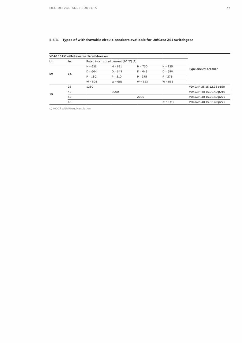
5.5.3. Types of withdrawable circuit-breakers available for UniGear ZS1 switchgear
VD4G 15 kV withdrawable circuit-breaker
Type circuit-breaker
Ur Isc Rated interrupted current (40 °C) [A]
kV kA
H = 632 H = 691 H = 730 H = 735
D = 664 D = 643 D = 643 D = 650
P = 150 P = 210 P = 275 P = 275
W = 503 W = 681 W = 853 W = 851
15
25 1250 VD4G/P-25 15.12.25 p150
40 2000 VD4G/P-40 15.20.40 p210
40 2000 VD4G/P-40 15.20.40 p275
40 3150 (1) VD4G/P-40 15.32.40 p275
(1) 4000 A with forced ventilation
14 V D 4 G - INS TA L L ATI O N A N D O PER ATI N G I NS TR U C TI O NS
(*) The minimum current that the relay with TCS function (used for monitoring coil continuity) detects as a condition denoting that the trip circuit is operating correctly (specified for each relay in the relative manual), must be sensibly higher than the current consumption of the actual coil (~1.5 mA).If this fails to occur, always add, in parallel to the TCS, a circuit able to absorb sufficient current to compensate the gap while preventing the total current in the TCS circuit from rising above the maximum threshold (Itcs < 10 mA for High Voltage coils - from 110V to 250V, and Itcs < 50 mA for Low Voltage coils from 24 V to 60 V).A simple resistor can be sized for the purpose, depending on the parameters of the TCS and the auxiliary voltage range used.
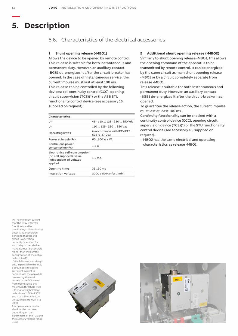
1 Shunt opening release (-MBO1) Allows the device to be opened by remote control. This release is suitable for both instantaneous and permanent duty. However, an auxiliary contact -BGB1 de-energizes it after the circuit-breaker has opened. In the case of instantaneous service, the current impulse must last at least 100 ms. This release can be controlled by the following devices: coil continuity control (CCC), opening circuit supervision (TCS)(*) or the ABB STU functionality control device (see accessory 16, supplied on request).
Characteristics
Un 48 - 110 ... 125 - 220 ... 250 Vdc
Un 110 ... 125 - 220 ... 250 Vac
Operating limits in accordance with IEC/IEEE 62271-37-013
Power at inrush (Ps) 60...100 W / VA
Continuous power consumption (Pc)
1.5 W
Electronics self-consumption(no coil supplied); valueindependent of voltage applied
1.5 mA
Opening time 33...60 ms
Insulation voltage 2000 V 50 Hz (for 1 min)
2 Additional shunt opening release (-MBO2) Similarly to shunt opening release -MBO1, this allows the opening command of the apparatus to be transmitted by remote control. It can be energized by the same circuit as main shunt opening release -MBO1 or by a circuit completely separate from release -MBO1.This release is suitable for both instantaneous and permanent duty. However, an auxiliary contact -BGB1 de-energizes it after the circuit-breaker has opened.To guarantee the release action, the current impulse must last at least 100 ms. Continuity functionality can be checked with a continuity control device (CCC), opening circuit supervision device (TCS)(*) or the STU functionality control device (see accessory 16, supplied on request).• MBO2 has the same electrical and operating
characteristics as release -MBO1.
—5. Description
5.6. Characteristics of the electrical accessories
M ED I U M VO LTAG E PR O D U C TS 15
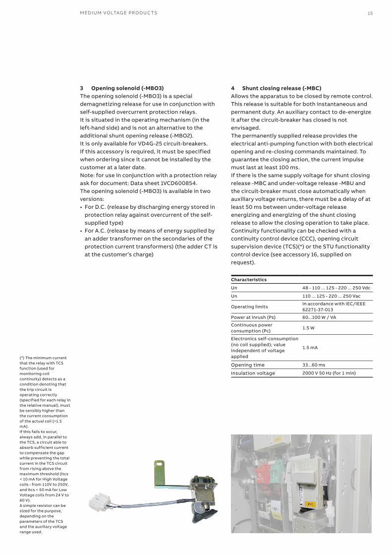
3 Opening solenoid (-MBO3) The opening solenoid (-MBO3) is a special demagnetizing release for use in conjunction with self-supplied overcurrent protection relays. It is situated in the operating mechanism (in the left-hand side) and is not an alternative to the additional shunt opening release (-MBO2).It is only available for VD4G-25 circuit-breakers.If this accessory is required, it must be specified when ordering since it cannot be installed by the customer at a later date. Note: for use in conjunction with a protection relay ask for document: Data sheet 1VCD600854.The opening solenoid (-MBO3) is available in two versions:• For D.C. (release by discharging energy stored in
protection relay against overcurrent of the self-supplied type)
• For A.C. (release by means of energy supplied by an adder transformer on the secondaries of the protection current transformers) (the adder CT is at the customer’s charge)
4 Shunt closing release (-MBC)Allows the apparatus to be closed by remote control. This release is suitable for both instantaneous and permanent duty. An auxiliary contact to de-energize it after the circuit-breaker has closed is not envisaged.The permanently supplied release provides the electrical anti-pumping function with both electrical opening and re-closing commands maintained. To guarantee the closing action, the current impulse must last at least 100 ms. If there is the same supply voltage for shunt closing release -MBC and under-voltage release -MBU and the circuit-breaker must close automatically when auxiliary voltage returns, there must be a delay of at least 50 ms between under-voltage release energizing and energizing of the shunt closing release to allow the closing operation to take place.Continuity functionality can be checked with a continuity control device (CCC), opening circuit supervision device (TCS)(*) or the STU functionality control device (see accessory 16, supplied on request).
Characteristics
Un 48 - 110 ... 125 - 220 ... 250 Vdc
Un 110 ... 125 - 220 ... 250 Vac
Operating limits in accordance with IEC/IEEE 62271-37-013
Power at inrush (Ps) 60...100 W / VA
Continuous power consumption (Pc)
1.5 W
Electronics self-consumption(no coil supplied); valueindependent of voltage applied
1.5 mA
Opening time 33...60 ms
Insulation voltage 2000 V 50 Hz (for 1 min)
(*) The minimum current that the relay with TCS function (used for monitoring coil continuity) detects as a condition denoting that the trip circuit is operating correctly (specified for each relay in the relative manual), must be sensibly higher than the current consumption of the actual coil (~1.5 mA).If this fails to occur, always add, in parallel to the TCS, a circuit able to absorb sufficient current to compensate the gap while preventing the total current in the TCS circuit from rising above the maximum threshold (Itcs < 10 mA for High Voltage coils - from 110V to 250V, and Itcs < 50 mA for Low Voltage coils from 24 V to 60 V).A simple resistor can be sized for the purpose, depending on the parameters of the TCS and the auxiliary voltage range used.

16 V D 4 G - INS TA L L ATI O N A N D O PER ATI N G I NS TR U C TI O NS
Consult circuit diagrams 1VCD400151 for fixed circuit-breakers and 1VCD400155 for plug-in circuit-breakers.
Note: The main shunt opening release and/or the additional shunt opening release use 1 and/or 2 closing contacts “a”, thereby reducing the number of auxiliary contacts available. Always check the maximum number of contacts available with non-standard equipment. Auxiliary contacts –BGB1 conform to the following standards/regulations/directives:• IEC 62271-100• IEEE C37.54• EN 61373 cat.1 class B / impact and vibration test• Germanish Loyd regulation / vibrations envisaged
by the shipping registers• UL 508• EN 60947 (DC-21A DC-22A DC-23A AC-21A)• RoHS Directive
5 Auxiliary contacts of circuit-breaker (-BGB1) for 15 kV versions
Electrical signaling of circuit-breaker open/closed can be obtained with a group of 10, 16 or 20 auxiliary contacts for the fixed version and 10 or 16 auxiliary contacts for the plug-in version. The standard equipment comprises 10 auxiliary contacts.
NoteThe following are available with the standard group of ten auxiliary contacts and the maximum number of electrical accessories:• for fixed circuit-breakers: three closing contacts
“a” for signaling circuit-breaker open and five opening contacts “b” for signaling circuit-breaker closed;
• for plug-in circuit-breakers: three closing contacts “a” for signaling circuit-breaker open and four opening contacts “b” for signaling circuit-breaker closed.
Circuit-breakers in the fixed version are available with two finishing accessories (to be specified when ordering): • non-wired auxiliary contacts; wiring to the
terminals of the contacts is at the customer’s charge (photo below left; the terminal box to which the other electrical accessories are wired is at the top); ask for instructions 1VCD601204 (available in the main languages) which describe how to remove, wire the auxiliary contact more easily and fit the group of auxiliary contacts back in place;
• auxiliary contacts already wired to the terminal box (see photo)
—5. Description
M ED I U M VO LTAG E PR O D U C TS 17
General characteristics
Insulation voltage to VDE 0110 standards, Group C
660 V A.C.800 V D.C.
Rated voltage 24 V ... 660 V
Test voltage 2 kV for 1 min
Maximum rated current 10 A - 50/60 Hz
Breaking capacity Class 1 (IEC 62271-1)
Number of contacts 5
Quantity of contacts 10 / 16 / 20
Contact travel 90°
Actuating force 0.66 Nm
Resistance <6,5 mΩ
Operating temperature –30 °C ... +120 °C
Operating temperature–20 °C ... +70 °C (-30° ref. ANSI 37.09)
Contact overtemperature 10 K
Mechanical life30,000 mechanical operations
Protection class IP20
Cable section 1 mm2
Electrical specifications (according to IEC 62271-100 class 1)
Rated voltage Un Breaking capacity
24 V D.C. 20 ms 18.8 A
60 V D.C. 20 ms 7.4 A
110 V D.C. 20 ms 4.2 A
250 V D.C. 20 ms 1.8 A
Electrical specifications (according to IEC 60947)
Rated voltage Un Breaking capacity (10000 breaks)
220 V A.C. Cosj = 0.70 20 A
220 V A.C. Cosj = 0.45 10 A
24 V D.C.
1 ms 12 A
15 ms 9 A
50 ms 6 A
60 V D.C.
1 ms 10 A
15 ms 6 A
50 ms 4.6 A
110 V D.C.
1 ms 7 A
15 ms 4.5 A
50 ms 3.5 A
220 V D.C.
1 ms 2 A
15 ms 1.7 A
50 ms 1.5 A
250 V D.C.
1 ms 2 A
15 ms 1.4 A
50 ms 1.2 A
18 V D 4 G - INS TA L L ATI O N A N D O PER ATI N G I NS TR U C TI O NS
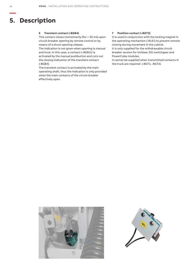
7 Position contact (-BGT3)It is used in conjunction with the locking magnet in the operating mechanism (-RLE1) to prevent remote closing during movement in the cubicle.It is only supplied for the withdrawable circuit-breaker version for UniGear ZS1 switchgear and PowerCube modules.It cannot be supplied when transmitted contacts in the truck are required (-BGT1; -BGT2).
—5. Description
6 Transient contact (-BGB4)This contact closes momentarily (for > 30 ms) upon circuit-breaker opening by remote control or by means of a shunt opening release.The indication is not given when opening is manual and local. In this case, a contact (–BGB11) is activated by the manual pushbutton and cuts out the closing indication of the transient contact(-BGB4).The transient contact is activated by the main operating shaft, thus the indication is only provided when the main contacts of the circuit-breaker effectively open.
M ED I U M VO LTAG E PR O D U C TS 19
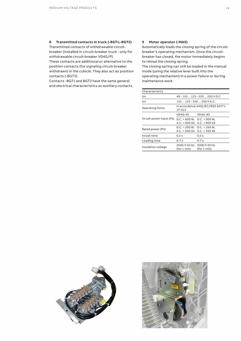
8 Transmitted contacts in truck (-BGT1;-BGT2)Transmitted contacts of withdrawable circuit-breaker (installed in circuit-breaker truck - only for withdrawable circuit-breaker VD4G/P).These contacts are additional or alternative to the position contacts (for signaling circuit-breaker withdrawn) in the cubicle. They also act as position contacts (-BGT3).Contacts -BGT1 and BGT2 have the same general and electrical characteristics as auxiliary contacts.
9 Motor operator (-MAS) Automatically loads the closing spring of the circuit-breaker’s operating mechanism. Once the circuit-breaker has closed, the motor immediately begins to reload the closing spring.The closing spring can still be loaded in the manual mode (using the relative lever built into the operating mechanism) in a power failure or during maintenance work.
Characteristics
Un 48 - 110 ... 125 - 220 ... 250 V D.C.
Un 110 ... 125 - 220 ... 250 V A.C.
Operating limitsin accordance withj IEC/IEEE 62271-37-013
Inrush power input (Ps)VD4G-25 VD4G-40
D.C. = 600 W; A.C. = 600 VA
D.C. = 900 W; A.C. = 900 VA
Rated power (Pn)D.C. = 200 W; A.C. = 200 VA
D.C. = 350 W; A.C. = 350 VA
Inrush time 0.2 s 0.2 s
Loading time 6-7 s 6-7 s
Insulation voltage 2000 V 50 Hz (for 1 min)
2000 V 50 Hz (for 1 min)
20 V D 4 G - INS TA L L ATI O N A N D O PER ATI N G I NS TR U C TI O NS
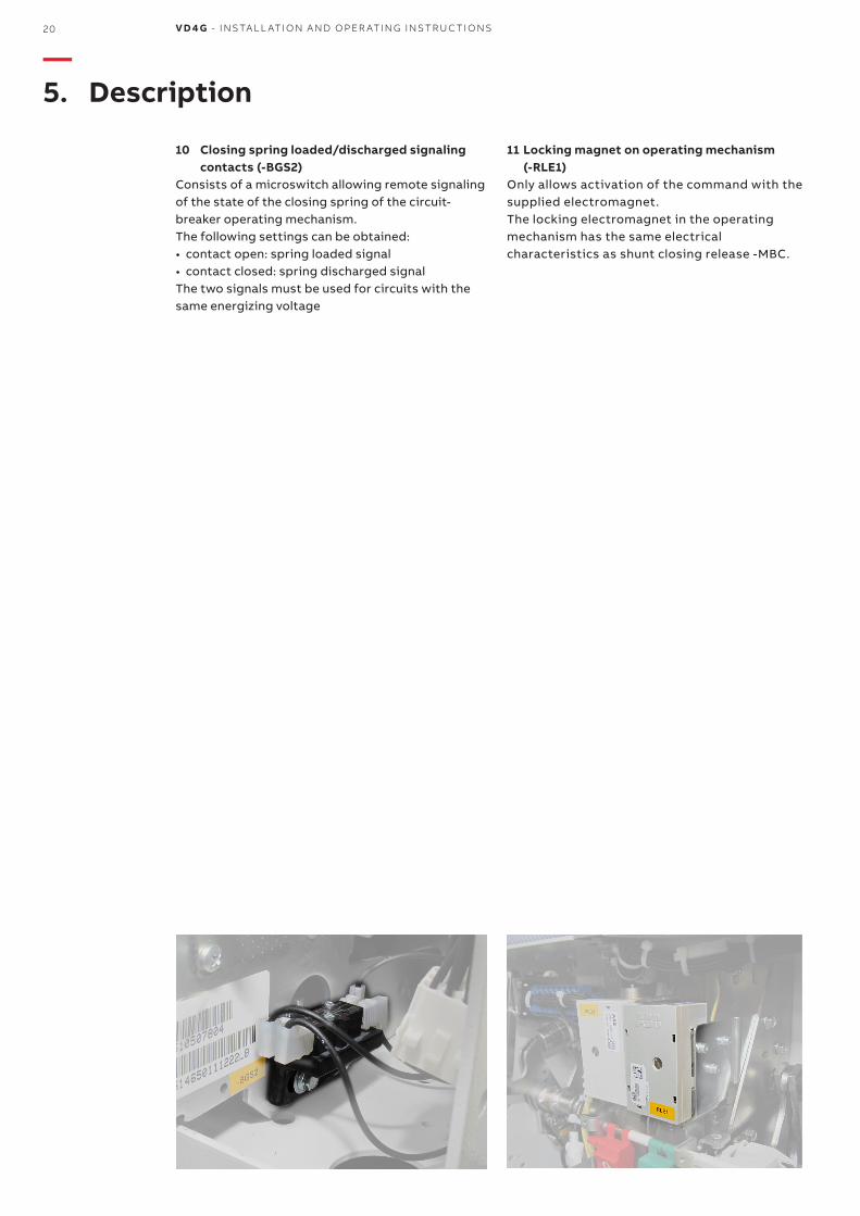
10 Closing spring loaded/discharged signaling contacts (-BGS2)
Consists of a microswitch allowing remote signaling of the state of the closing spring of the circuit-breaker operating mechanism. The following settings can be obtained:• contact open: spring loaded signal• contact closed: spring discharged signalThe two signals must be used for circuits with the same energizing voltage
—5. Description
11 Locking magnet on operating mechanism (-RLE1)
Only allows activation of the command with the supplied electromagnet.The locking electromagnet in the operating mechanism has the same electrical characteristics as shunt closing release -MBC.
M ED I U M VO LTAG E PR O D U C TS 21
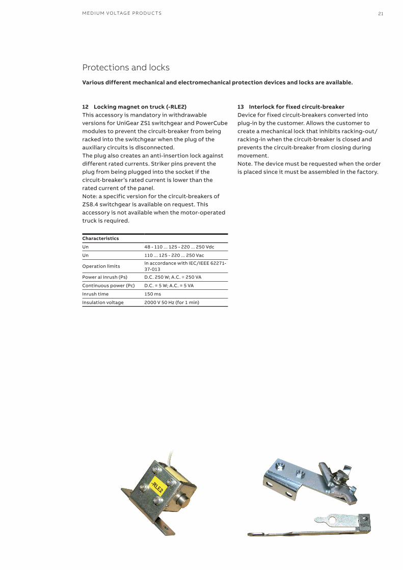
12 Locking magnet on truck (-RLE2)This accessory is mandatory in withdrawable versions for UniGear ZS1 switchgear and PowerCube modules to prevent the circuit-breaker from being racked into the switchgear when the plug of the auxiliary circuits is disconnected. The plug also creates an anti-insertion lock against different rated currents. Striker pins prevent the plug from being plugged into the socket if the circuit-breaker’s rated current is lower than the rated current of the panel.Note: a specific version for the circuit-breakers of ZS8.4 switchgear is available on request. This accessory is not available when the motor-operated truck is required.
Characteristics
Un 48 - 110 ... 125 - 220 ... 250 Vdc
Un 110 ... 125 - 220 ... 250 Vac
Operation limitsin accordance with IEC/IEEE 62271-37-013
Power ai inrush (Ps) D.C. 250 W; A.C. = 250 VA
Continuous power (Pc) D.C. = 5 W; A.C. = 5 VA
Inrush time 150 ms
Insulation voltage 2000 V 50 Hz (for 1 min)
13 Interlock for fixed circuit-breakerDevice for fixed circuit-breakers converted into plug-in by the customer. Allows the customer to create a mechanical lock that inhibits racking-out/racking-in when the circuit-breaker is closed and prevents the circuit-breaker from closing during movement. Note. The device must be requested when the order is placed since it must be assembled in the factory.
Protections and locks
Various different mechanical and electromechanical protection devices and locks are available.
22 V D 4 G - INS TA L L ATI O N A N D O PER ATI N G I NS TR U C TI O NS
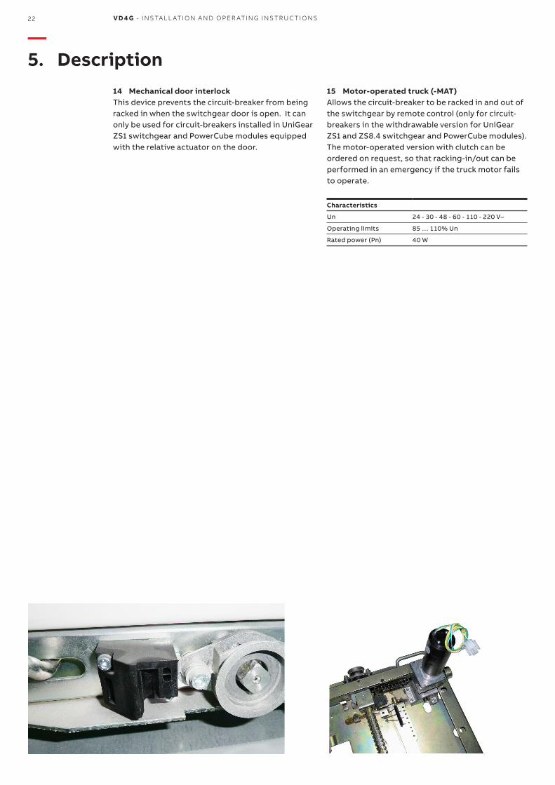
14 Mechanical door interlockThis device prevents the circuit-breaker from being racked in when the switchgear door is open. It can only be used for circuit-breakers installed in UniGear ZS1 switchgear and PowerCube modules equipped with the relative actuator on the door.
15 Motor-operated truck (-MAT) Allows the circuit-breaker to be racked in and out of the switchgear by remote control (only for circuit-breakers in the withdrawable version for UniGear ZS1 and ZS8.4 switchgear and PowerCube modules). The motor-operated version with clutch can be ordered on request, so that racking-in/out can be performed in an emergency if the truck motor fails to operate.
Characteristics
Un 24 - 30 - 48 - 60 - 110 - 220 V–
Operating limits 85 … 110% Un
Rated power (Pn) 40 W
—5. Description
M ED I U M VO LTAG E PR O D U C TS 23
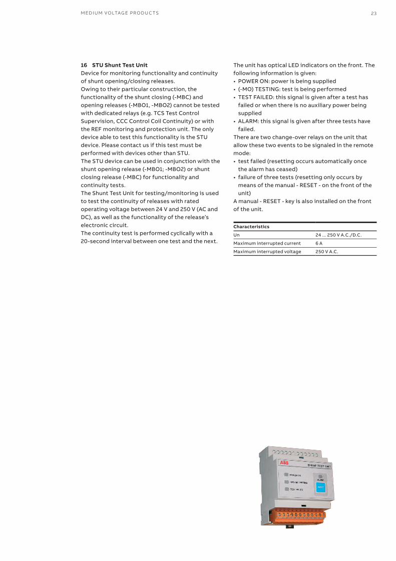
16 STU Shunt Test Unit Device for monitoring functionality and continuity of shunt opening/closing releases. Owing to their particular construction, the functionality of the shunt closing (-MBC) and opening releases (-MBO1, -MBO2) cannot be tested with dedicated relays (e.g. TCS Test Control Supervision, CCC Control Coil Continuity) or with the REF monitoring and protection unit. The only device able to test this functionality is the STU device. Please contact us if this test must be performed with devices other than STU.The STU device can be used in conjunction with the shunt opening release (-MBO1; -MBO2) or shunt closing release (-MBC) for functionality and continuity tests.The Shunt Test Unit for testing/monitoring is used to test the continuity of releases with rated operating voltage between 24 V and 250 V (AC and DC), as well as the functionality of the release’s electronic circuit.The continuity test is performed cyclically with a 20-second interval between one test and the next.
The unit has optical LED indicators on the front. The following information is given:• POWER ON: power is being supplied• (-MO) TESTING: test is being performed• TEST FAILED: this signal is given after a test has
failed or when there is no auxiliary power being supplied
• ALARM: this signal is given after three tests have failed.
There are two change-over relays on the unit that allow these two events to be signaled in the remote mode: • test failed (resetting occurs automatically once
the alarm has ceased)• failure of three tests (resetting only occurs by
means of the manual - RESET - on the front of the unit)
A manual - RESET - key is also installed on the front of the unit.
Characteristics
Un 24 ... 250 V A.C./D.C.
Maximum interrupted current 6 A
Maximum interrupted voltage 250 V A.C.
5
1
2
6
4
3
9
7
8
10
24 V D 4 G - INS TA L L ATI O N A N D O PER ATI N G I NS TR U C TI O NS
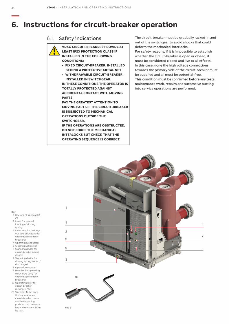
—6. Instructions for circuit-breaker operation
6.1. Safety indications
VD4G CIRCUIT-BREAKERS PROVIDE AT LEAST IP2X PROTECTION CLASS IF INSTALLED IN THE FOLLOWING CONDITIONS:
• FIXED CIRCUIT-BREAKER, INSTALLED BEHIND A PROTECTIVE METAL NET
• WITHDRAWABLE CIRCUIT-BREAKER, INSTALLED IN SWITCHGEAR.
IN THESE CONDITIONS THE OPERATOR IS TOTALLY PROTECTED AGAINST ACCIDENTAL CONTACT WITH MOVING PARTS.
PAY THE GREATEST ATTENTION TO MOVING PARTS IF THE CIRCUIT-BREAKER IS SUBJECTED TO MECHANICAL OPERATIONS OUTSIDE THE SWITCHGEAR.
IF THE OPERATIONS ARE OBSTRUCTED, DO NOT FORCE THE MECHANICAL INTERLOCKS BUT CHECK THAT THE OPERATING SEQUENCE IS CORRECT.
The circuit-breaker must be gradually racked-in and out of the switchgear to avoid shocks that could deform the mechanical interlocks. For safety reasons, if it is impossible to establish whether the circuit-breaker is open or closed, it must be considered closed and live to all effects.In this case, none the high voltage connections towards the primary side of the circuit-breaker must be supplied and all must be potential-free. This condition must be confirmed before any tests, maintenance work, repairs and successive putting into service operations are performed.
Key 1 Key lock (if applicable)
(*) 2 Lever for manual
loading of closing spring
3 Lever seat for racking-out operation (only for withdrawable circuit-breakers)
4 Opening pushbutton 5 Closing pushbutton 6 Signaling device for
circuit-breaker open/closed
7 Signaling device for closing spring loaded/discharged
8 Operation counter 9 Handles for operating
truck locks (only for withdrawable circuit-breakers)
10 Operating lever for circuit-breaker racking-in/out
(*) Warning! To activate the key lock: open circuit-breaker, press and hold opening pushbutton, then turn key and remove it from its seat.
Fig. 6
M ED I U M VO LTAG E PR O D U C TS 25
6.2. Operating and signaling components
VD4G circuit-breakers for UniGear switchgear and PowerCube modules (fig. 6)
6.3. Circuit-breaker closing and opening operations
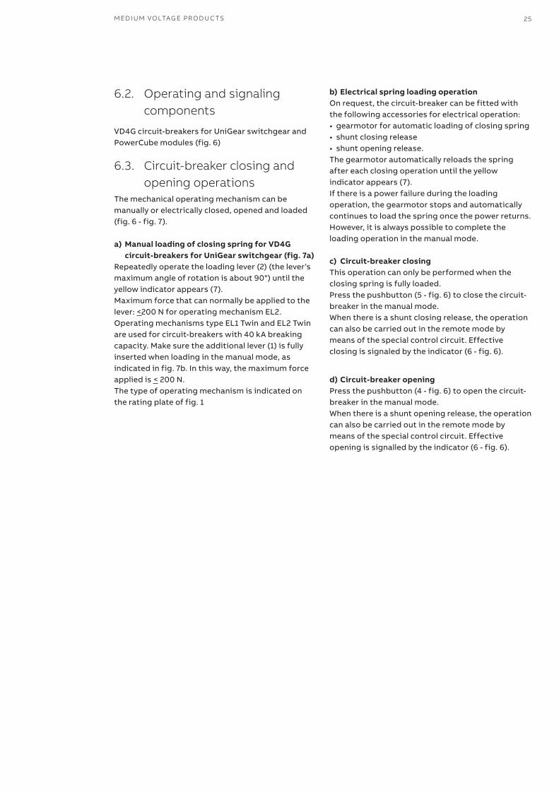
The mechanical operating mechanism can be manually or electrically closed, opened and loaded (fig. 6 - fig. 7).
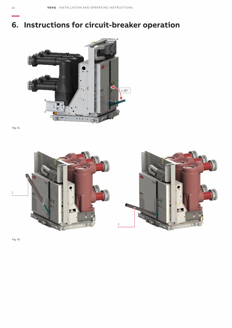
a) Manual loading of closing spring for VD4G circuit-breakers for UniGear switchgear (fig. 7a)
Repeatedly operate the loading lever (2) (the lever’s maximum angle of rotation is about 90°) until the yellow indicator appears (7).Maximum force that can normally be applied to the lever: <200 N for operating mechanism EL2. Operating mechanisms type EL1 Twin and EL2 Twin are used for circuit-breakers with 40 kA breaking capacity. Make sure the additional lever (1) is fully inserted when loading in the manual mode, as indicated in fig. 7b. In this way, the maximum force applied is < 200 N.The type of operating mechanism is indicated on the rating plate of fig. 1
b) Electrical spring loading operationOn request, the circuit-breaker can be fitted with the following accessories for electrical operation: • gearmotor for automatic loading of closing spring • shunt closing release • shunt opening release. The gearmotor automatically reloads the spring after each closing operation until the yellow indicator appears (7). If there is a power failure during the loading operation, the gearmotor stops and automatically continues to load the spring once the power returns. However, it is always possible to complete the loading operation in the manual mode.
c) Circuit-breaker closing This operation can only be performed when the closing spring is fully loaded. Press the pushbutton (5 - fig. 6) to close the circuit-breaker in the manual mode.When there is a shunt closing release, the operation can also be carried out in the remote mode by means of the special control circuit. Effective closing is signaled by the indicator (6 - fig. 6).
d) Circuit-breaker opening Press the pushbutton (4 - fig. 6) to open the circuit-breaker in the manual mode.When there is a shunt opening release, the operation can also be carried out in the remote mode by means of the special control circuit. Effective opening is signalled by the indicator (6 - fig. 6).
≈ 90°
1
1
26 V D 4 G - INS TA L L ATI O N A N D O PER ATI N G I NS TR U C TI O NS
Fig. 7a
Fig. 7b
—6. Instructions for circuit-breaker operation
M ED I U M VO LTAG E PR O D U C TS 27
—7. Installation
7.1. General information
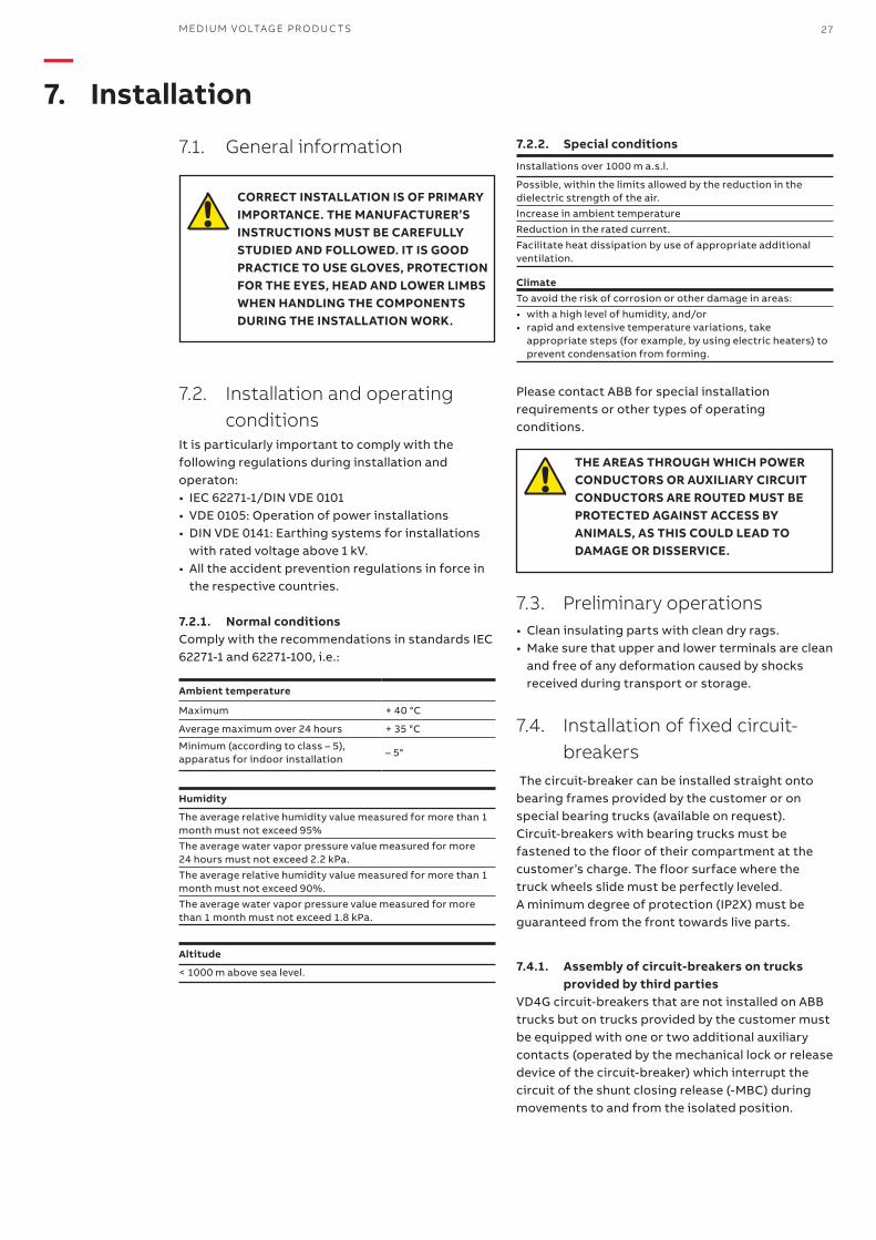
CORRECT INSTALLATION IS OF PRIMARY IMPORTANCE. THE MANUFACTURER’S INSTRUCTIONS MUST BE CAREFULLY STUDIED AND FOLLOWED. IT IS GOOD PRACTICE TO USE GLOVES, PROTECTION FOR THE EYES, HEAD AND LOWER LIMBS WHEN HANDLING THE COMPONENTS DURING THE INSTALLATION WORK.
7.2. Installation and operating conditions
It is particularly important to comply with the following regulations during installation and operaton:• IEC 62271-1/DIN VDE 0101• VDE 0105: Operation of power installations• DIN VDE 0141: Earthing systems for installations
with rated voltage above 1 kV.• All the accident prevention regulations in force in
the respective countries.
7.2.1. Normal conditionsComply with the recommendations in standards IEC 62271-1 and 62271-100, i.e.:
Humidity
The average relative humidity value measured for more than 1 month must not exceed 95%The average water vapor pressure value measured for more 24 hours must not exceed 2.2 kPa.The average relative humidity value measured for more than 1 month must not exceed 90%.The average water vapor pressure value measured for more than 1 month must not exceed 1.8 kPa.
Altitude
< 1000 m above sea level.
Ambient temperature
Maximum + 40 °C
Average maximum over 24 hours + 35 °C
Minimum (according to class – 5), apparatus for indoor installation
– 5°
7.2.2. Special conditions
Installations over 1000 m a.s.l.
Possible, within the limits allowed by the reduction in the dielectric strength of the air.Increase in ambient temperatureReduction in the rated current.Facilitate heat dissipation by use of appropriate additional ventilation.
ClimateTo avoid the risk of corrosion or other damage in areas:• with a high level of humidity, and/or• rapid and extensive temperature variations, take
appropriate steps (for example, by using electric heaters) to prevent condensation from forming.
Please contact ABB for special installation requirements or other types of operating conditions.
THE AREAS THROUGH WHICH POWER CONDUCTORS OR AUXILIARY CIRCUIT CONDUCTORS ARE ROUTED MUST BE PROTECTED AGAINST ACCESS BY ANIMALS, AS THIS COULD LEAD TO DAMAGE OR DISSERVICE.
7.3. Preliminary operations • Clean insulating parts with clean dry rags. • Make sure that upper and lower terminals are clean
and free of any deformation caused by shocks received during transport or storage.
7.4. Installation of fixed circuit-breakers
The circuit-breaker can be installed straight onto bearing frames provided by the customer or on special bearing trucks (available on request). Circuit-breakers with bearing trucks must be fastened to the floor of their compartment at the customer’s charge. The floor surface where the truck wheels slide must be perfectly leveled. A minimum degree of protection (IP2X) must be guaranteed from the front towards live parts.
7.4.1. Assembly of circuit-breakers on trucks provided by third parties
VD4G circuit-breakers that are not installed on ABB trucks but on trucks provided by the customer must be equipped with one or two additional auxiliary contacts (operated by the mechanical lock or release device of the circuit-breaker) which interrupt the circuit of the shunt closing release (-MBC) during movements to and from the isolated position.
28 V D 4 G - INS TA L L ATI O N A N D O PER ATI N G I NS TR U C TI O NS
This function is performed on ABB trucks by auxiliary contacts -BGT1 and -BGT2, which shut off the power supplied to the release during and before activation of the mechanical lock of the truck’s screw insertion device. This means that power can only be supplied to the shunt closing release after activation of the mechanical lock. No electrical impulse is therefore able to activate the shunt closing release when the circuit-breaker is in the intermediate position.
7.5. Installation of withdrawable circuit-breakers
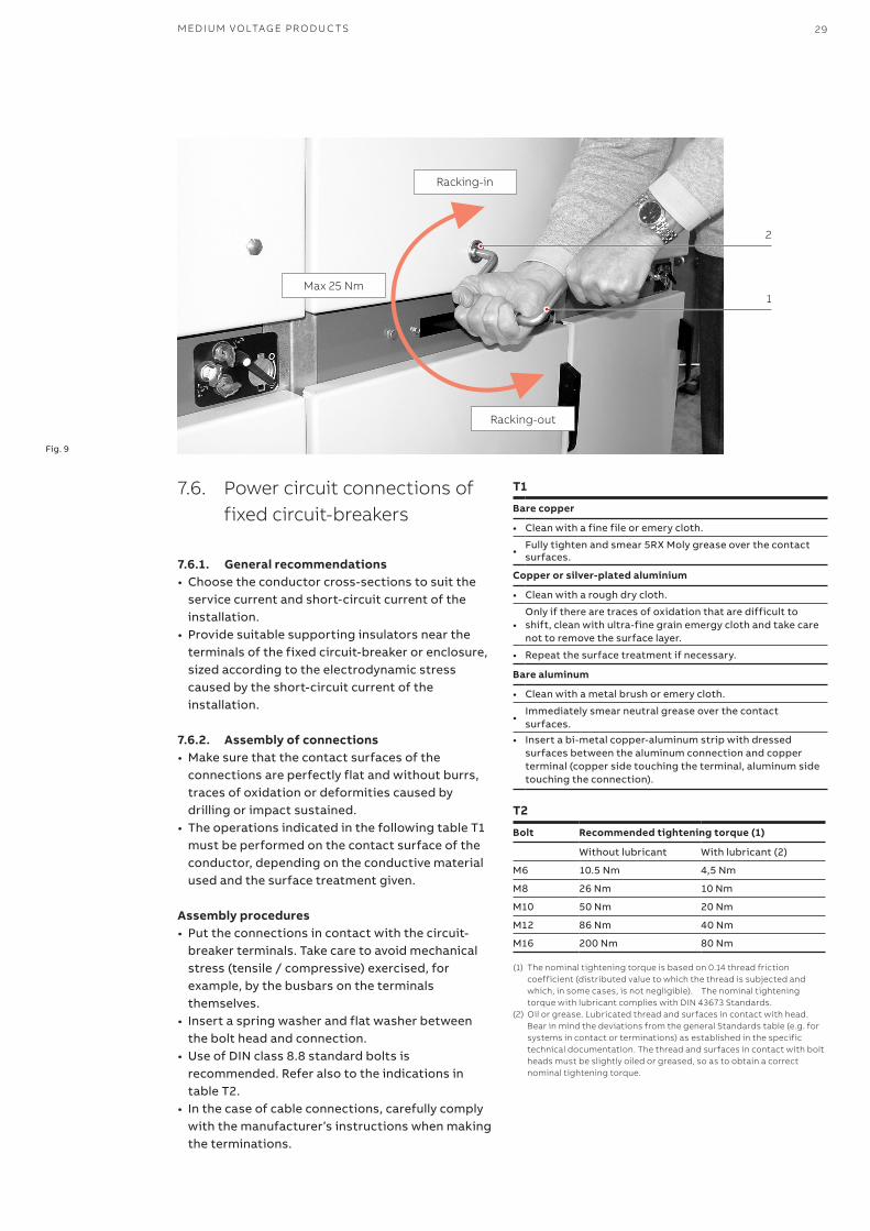
The withdrawable circuit-breakers are designed for use in UniGear ZS1 switchgear. To rack the circuit-breaker in and out of the switchgear, fully insert the lever (1) (fig. 9) into its seat (2) and turn it clockwise to rack-in or counter-clockwise to rack-out until reaching the end of travel positions. The circuit-breaker must be gradually racked-in and out to avoid shocks that could deform the mechanical interlocks and limit switches.The torque normally required for racking-in and out is < 25 Nm. Never exceed this value. If the operations are obstructed in any way or difficult to perform, do not apply force but check that the operating sequence is correct.
NoteTo complete the racking-in or out operations, the lever must be turned about 20 times for circuit-breakers up to 17.5 kV and about 30 times for 24 kV circuit-breakers.
When the circuit-breaker has reached the isolated for test/isolated position, it can be considered to have been racked into the switchgear and earthed by means of the truck wheels.Withdrawable circuit-breakers of the same version, thus of the same size, are interchangeable. However, when, for example, the electrical accessories are different, the plug of the auxiliary circuits will have a different code and prevent panels and circuit-breakers from being wrongly paired.The technical documentation of the switchgear should also be consulted when installing the circuit-breakers.
• THE RACKING-IN/OUT OPERATIONS MUST ALWAYS BE PERFORMED WITH THE CIRCUIT-BREAKER OPEN.
• WHEN PUTTING INTO SERVICE FOR THE FIRST TIME, ALWAYS LOAD THE CIRCUIT-BREAKER OPERATING MECHANISMS IN THE MANUAL MODE TO AVOID OVERLOADING THE AUXILIARY SUPPLY CIRCUIT.
7.5.1. Circuit-breakers with motor-operated withdrawable trucks
Perform the racking-in/out test for the motor-operated truck in the same way as the manual truck and comply with the following instructions:• Rack the circuit-breaker into the switchgear in the
open and isolated position, with the supply circuit of the motor de-energized and the enclosure door closed.
• Fit the manual racking-in lever (1) into its seat (2) 9 and move the motor-operated truck to about halfway along its travel, between the isolated for test and connected positions. The torque required to move the truck is < 25 Nm.
• This operation allows you to deal with movements in the wrong direction without damage should the polarity of the truck motor supply accidentally reverse. Verifications:
a) clockwise motor rotation when circuit-breaker is racked in. b) counter-clockwise motor rotation when circuit- breaker is racked out.• Remove the manual lever (1) from its seat (2) 9• Energize the truck motor circuit.• Activate the operating mechanism for electrical
racking-in. After racking-in, make sure that the relative auxiliary contact has switched correctly.
• At the end of the sequence, activate the operating mechanism for electrical racking-out. After racking-out, make sure that the relative auxiliary contact has switched correctly.
• If a motor fault occurs during a racking-in or out operation, the truck can be moved to end of travel in an emergency by first shutting off the voltage supplied to the motor supply circuit and then using the manual lever in the same way as for truck operation in the manual mode.
NoteWhen the manual lever is used to operate the truck, the chain transmission turns the truck motor which, by acting as a generator, can produce reverse voltage towards the connection terminals. Since this can damage the permanent magnet of the motor, all truck racking-in and out operations with the manual lever must be performed with the motor circuit de-energized.
—7. Installation
2
1Max 25 Nm
M ED I U M VO LTAG E PR O D U C TS 29
7.6. Power circuit connections of fixed circuit-breakers
7.6.1. General recommendations • Choose the conductor cross-sections to suit the
service current and short-circuit current of the installation.
• Provide suitable supporting insulators near the terminals of the fixed circuit-breaker or enclosure, sized according to the electrodynamic stress caused by the short-circuit current of the installation.
7.6.2. Assembly of connections• Make sure that the contact surfaces of the
connections are perfectly flat and without burrs, traces of oxidation or deformities caused by drilling or impact sustained.
• The operations indicated in the following table T1 must be performed on the contact surface of the conductor, depending on the conductive material used and the surface treatment given.
Assembly procedures• Put the connections in contact with the circuit-
breaker terminals. Take care to avoid mechanical stress (tensile / compressive) exercised, for example, by the busbars on the terminals themselves.
• Insert a spring washer and flat washer between the bolt head and connection.
• Use of DIN class 8.8 standard bolts is recommended. Refer also to the indications in table T2.
• In the case of cable connections, carefully comply with the manufacturer’s instructions when making the terminations.
T1
Bare copper
• Clean with a fine file or emery cloth.
• Fully tighten and smear 5RX Moly grease over the contact surfaces.
Copper or silver-plated aluminium
• Clean with a rough dry cloth.
• Only if there are traces of oxidation that are difficult to shift, clean with ultra-fine grain emergy cloth and take care not to remove the surface layer.
• Repeat the surface treatment if necessary.
Bare aluminum
• Clean with a metal brush or emery cloth.
• Immediately smear neutral grease over the contact surfaces.
• Insert a bi-metal copper-aluminum strip with dressed surfaces between the aluminum connection and copper terminal (copper side touching the terminal, aluminum side touching the connection).
T2
Bolt Recommended tightening torque (1)
Without lubricant With lubricant (2)
M6 10.5 Nm 4,5 Nm
M8 26 Nm 10 Nm
M10 50 Nm 20 Nm
M12 86 Nm 40 Nm
M16 200 Nm 80 Nm (1) The nominal tightening torque is based on 0.14 thread friction
coefficient (distributed value to which the thread is subjected and which, in some cases, is not negligible). The nominal tightening torque with lubricant complies with DIN 43673 Standards.
(2) Oil or grease. Lubricated thread and surfaces in contact with head. Bear in mind the deviations from the general Standards table (e.g. for systems in contact or terminations) as established in the specific technical documentation. The thread and surfaces in contact with bolt heads must be slightly oiled or greased, so as to obtain a correct nominal tightening torque.
Racking-in
Racking-out
Fig. 9
1
2
30 V D 4 G - INS TA L L ATI O N A N D O PER ATI N G I NS TR U C TI O NS
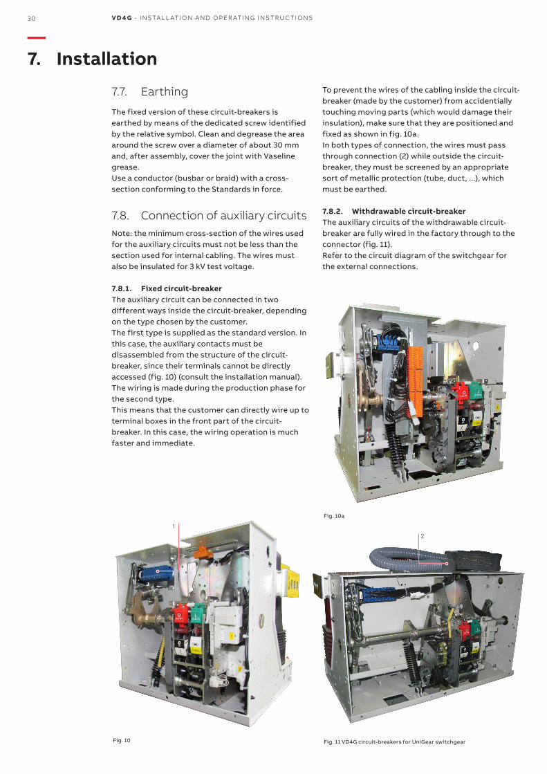
To prevent the wires of the cabling inside the circuit-breaker (made by the customer) from accidentially touching moving parts (which would damage their insulation), make sure that they are positioned and fixed as shown in fig. 10a.In both types of connection, the wires must pass through connection (2) while outside the circuit-breaker, they must be screened by an appropriate sort of metallic protection (tube, duct, ...), which must be earthed.
7.8.2. Withdrawable circuit-breakerThe auxiliary circuits of the withdrawable circuit-breaker are fully wired in the factory through to the connector (fig. 11). Refer to the circuit diagram of the switchgear for the external connections.
Fig. 11 VD4G circuit-breakers for UniGear switchgear
7.7. Earthing
The fixed version of these circuit-breakers is earthed by means of the dedicated screw identified by the relative symbol. Clean and degrease the area around the screw over a diameter of about 30 mm and, after assembly, cover the joint with Vaseline grease. Use a conductor (busbar or braid) with a cross-section conforming to the Standards in force.
7.8. Connection of auxiliary circuitsNote: the minimum cross-section of the wires used for the auxiliary circuits must not be less than the section used for internal cabling. The wires must also be insulated for 3 kV test voltage.
7.8.1. Fixed circuit-breakerThe auxiliary circuit can be connected in two different ways inside the circuit-breaker, depending on the type chosen by the customer.The first type is supplied as the standard version. In this case, the auxiliary contacts must be disassembled from the structure of the circuit-breaker, since their terminals cannot be directly accessed (fig. 10) (consult the installation manual).The wiring is made during the production phase for the second type. This means that the customer can directly wire up to terminal boxes in the front part of the circuit-breaker. In this case, the wiring operation is much faster and immediate.
Fig. 10
Fig. 10a
—7. Installation

M ED I U M VO LTAG E PR O D U C TS 31
—8. Putting into service
8.1. General procedures
ALL THE OPERATIONS FOR PUTTING INTO SERVICE MUST BE PERFORMED BY ABB PERSONNEL OR BY THE CUSTOMER’S ADEQUATELY QUALIFIED PERSONNEL WITH DETAILED KNOWLEDGE OF THE APPARATUS AND INSTALLATION.
IF THE OPERATIONS ARE OBSTRUCTED, DO NOT FORCE THE MECHANICAL INTERLOCKS BUT CHECK THAT THE OPERATING SEQUENCE IS CORRECT.
THE OPERATING FORCES TO APPLY WHEN RACKING-IN WITHDRAWABLE CIRCUIT-BREAKERS ARE INDICATED IN SECTION 7.5.
Perform the following operations before putting the circuit-breaker into service: • make sure that the power connections to the
circuit-breaker terminals are tight; • establish the setting of the electronic primary
overcurrent release (if applicable); • make sure that the value of the voltage supplied to
the auxiliary circuits is between 85% and 110% of the rated voltage of the electrical applications;
• make sure that there are no foreign bodies, such as bits of packing, between the moving parts;
• to avoid overtemperatures, make sure that there is a sufficient exchange of air in the installation site;
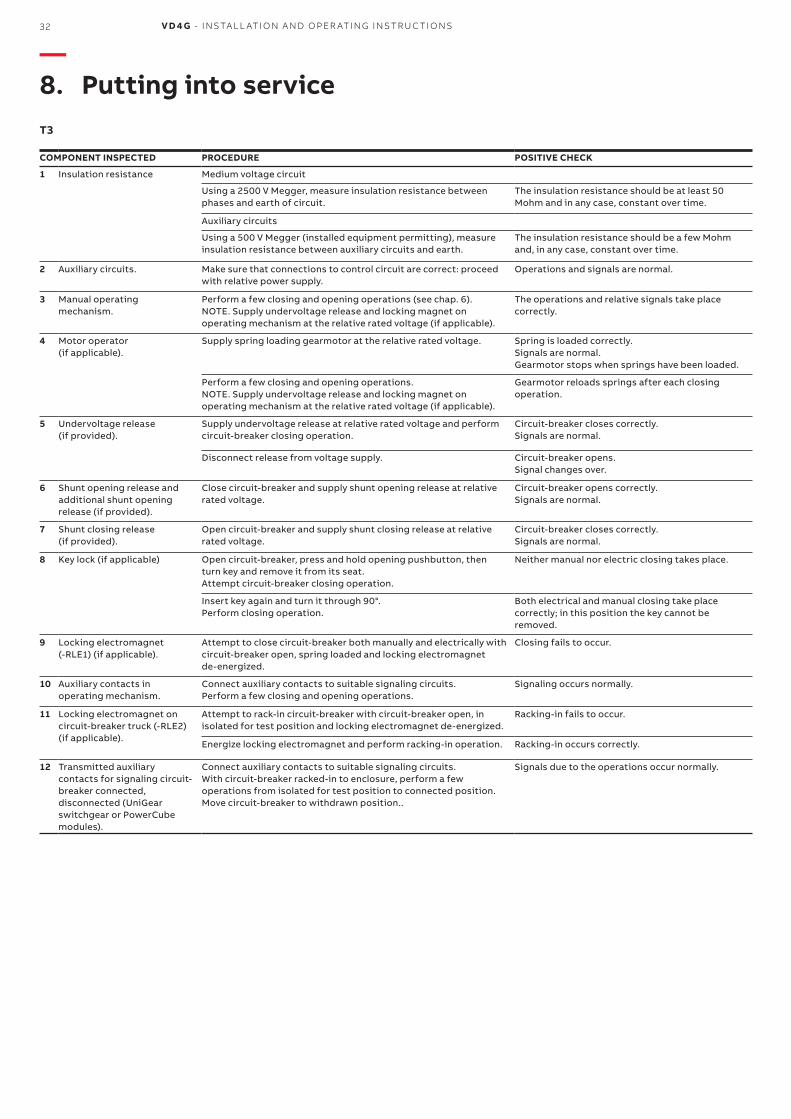
• also perform the inspections indicated in table T3.
32 V D 4 G - INS TA L L ATI O N A N D O PER ATI N G I NS TR U C TI O NS
COMPONENT INSPECTED PROCEDURE POSITIVE CHECK
1 Insulation resistance Medium voltage circuit
Using a 2500 V Megger, measure insulation resistance between phases and earth of circuit.
The insulation resistance should be at least 50 Mohm and in any case, constant over time.
Auxiliary circuits
Using a 500 V Megger (installed equipment permitting), measure insulation resistance between auxiliary circuits and earth.
The insulation resistance should be a few Mohm and, in any case, constant over time.
2 Auxiliary circuits. Make sure that connections to control circuit are correct: proceed with relative power supply.
Operations and signals are normal.
3 Manual operating mechanism.
Perform a few closing and opening operations (see chap. 6). NOTE. Supply undervoltage release and locking magnet on operating mechanism at the relative rated voltage (if applicable).
The operations and relative signals take place correctly.
4 Motor operator (if applicable).
Supply spring loading gearmotor at the relative rated voltage. Spring is loaded correctly.Signals are normal. Gearmotor stops when springs have been loaded.
Perform a few closing and opening operations. NOTE. Supply undervoltage release and locking magnet on operating mechanism at the relative rated voltage (if applicable).
Gearmotor reloads springs after each closing operation.
5 Undervoltage release (if provided).
Supply undervoltage release at relative rated voltage and perform circuit-breaker closing operation.
Circuit-breaker closes correctly.Signals are normal.
Disconnect release from voltage supply. Circuit-breaker opens.Signal changes over.
6 Shunt opening release and additional shunt opening release (if provided).
Close circuit-breaker and supply shunt opening release at relative rated voltage.
Circuit-breaker opens correctly.Signals are normal.
7 Shunt closing release (if provided).
Open circuit-breaker and supply shunt closing release at relative rated voltage.
Circuit-breaker closes correctly. Signals are normal.
8 Key lock (if applicable) Open circuit-breaker, press and hold opening pushbutton, then turn key and remove it from its seat.Attempt circuit-breaker closing operation.
Neither manual nor electric closing takes place.
Insert key again and turn it through 90°. Perform closing operation.
Both electrical and manual closing take place correctly; in this position the key cannot be removed.
9 Locking electromagnet (-RLE1) (if applicable).
Attempt to close circuit-breaker both manually and electrically with circuit-breaker open, spring loaded and locking electromagnet de-energized.
Closing fails to occur.
10 Auxiliary contacts in operating mechanism.
Connect auxiliary contacts to suitable signaling circuits. Perform a few closing and opening operations.
Signaling occurs normally.
11 Locking electromagnet on circuit-breaker truck (-RLE2) (if applicable).
Attempt to rack-in circuit-breaker with circuit-breaker open, in isolated for test position and locking electromagnet de-energized.
Racking-in fails to occur.
Energize locking electromagnet and perform racking-in operation. Racking-in occurs correctly.
12 Transmitted auxiliary contacts for signaling circuit-breaker connected, disconnected (UniGear switchgear or PowerCube modules).
Connect auxiliary contacts to suitable signaling circuits. With circuit-breaker racked-in to enclosure, perform a few operations from isolated for test position to connected position.Move circuit-breaker to withdrawn position..
Signals due to the operations occur normally.
T3
—8. Putting into service
M ED I U M VO LTAG E PR O D U C TS 33
The purpose of maintenance is to keep the apparatus in a good working condition for as long as possible. The following operations must be performed in accordance with the specifications given in standards IEC 61208 / DIN 31 051:Inspection: Finding out the actual conditionsServicing: Measures to be taken to maintain the specific conditionsRepair: Measures to be taken to restore the specific conditions.
9.1. General informationVacuum circuit-breakers are characterized by simple, sturdy construction and long life.The operating mechanism requires functional inspections and maintenance if it is to remain operative throughout its forecast life cycle (see sect. 9.3.2.).The vacuum interrupters are maintenance-free for their whole operating life.Vacuum interruption does not produce harmful effects even when there are frequent interruptions in the rated and short-circuit current.Interventions during service and their purpose are determined by the ambient conditions, the sequence of operations and shortcircuit interruptions.
NoteComply with the following regulations for maintenance work:• the relative specifications given in the chapter on “Standards and
Specifications”;• the labor safety regulations in the chapter on “Putting into service and
operations”;• the standards and specifications in force in the country where the
apparatus is installed.
Maintenance operations must only be carried out by personnel who have been trained and who comply with all the safety regulations. In addition, it is advisable to have ABB personnel at least check performance during service and carry out any repairs required.Cut off the power supply and ensure the apparatus is in a safe condition during maintenance.
BEFORE PROCEEDING WITH ANY OPERATION, MAKE SURE THAT THE CIRCUIT-BREAKER IS OPEN, WITH THE SPRING DISCHARGED AND THAT IT IS NOT POWERED (MEDIUM VOLTAGE CIRCUIT AND AUXILIARY CIRCUITS).
9.1.1. Operating lifeThe operating life expectancy of VD4G circuit-breakers is as follows: • vacuum interrupters: up to 30,000 mechanical
operations• actuator and transmission system: up to 30,000
operations, under normal operating conditions, depending on the type of circuit-breaker and with regular maintenance (see sect. 9.3.2.);
• racking-in/out can be performed up to 1000 times if the operations are carried out correctly (as required by standard IEC 60271-200);
• the operating life data are basically applicable to all components that are not directly influenced by the operator’s tasks. The behavior of components operated in the manual mode (moving components of disconnectable parts, etc.) can vary.
9.2. Inspections and functionality tests
9.2.1. Pole and conductive parts• Regularly inspect the conditions of the conductive
parts.• Inspection at fixed intervals can be avoided when
the apparatus is permanently under the control of qualified personnel.
• Firstly, the assessments must include visual inspection to check for any contamination, traces of corrosion or electrical discharge.
• Perform more frequent inspections when there are unusual operating conditions (including severe climatic conditions) and in the case of environmental pollution (e.g. high level of contamination or an aggressive atmosphere).
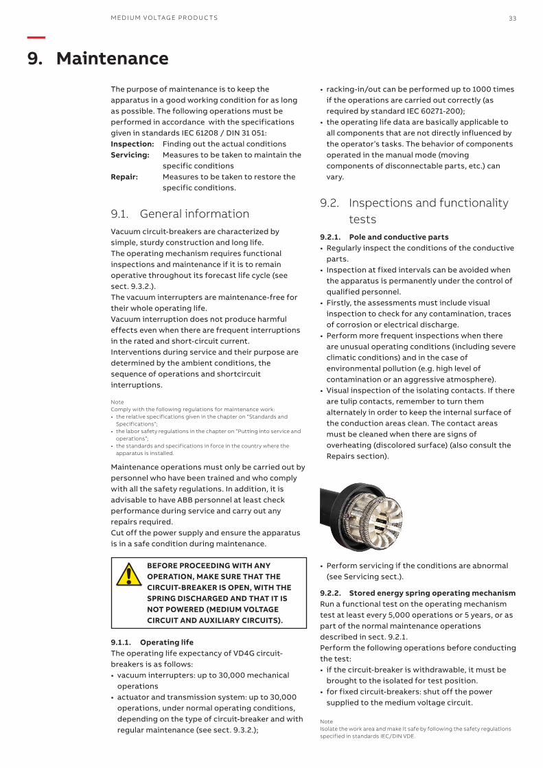
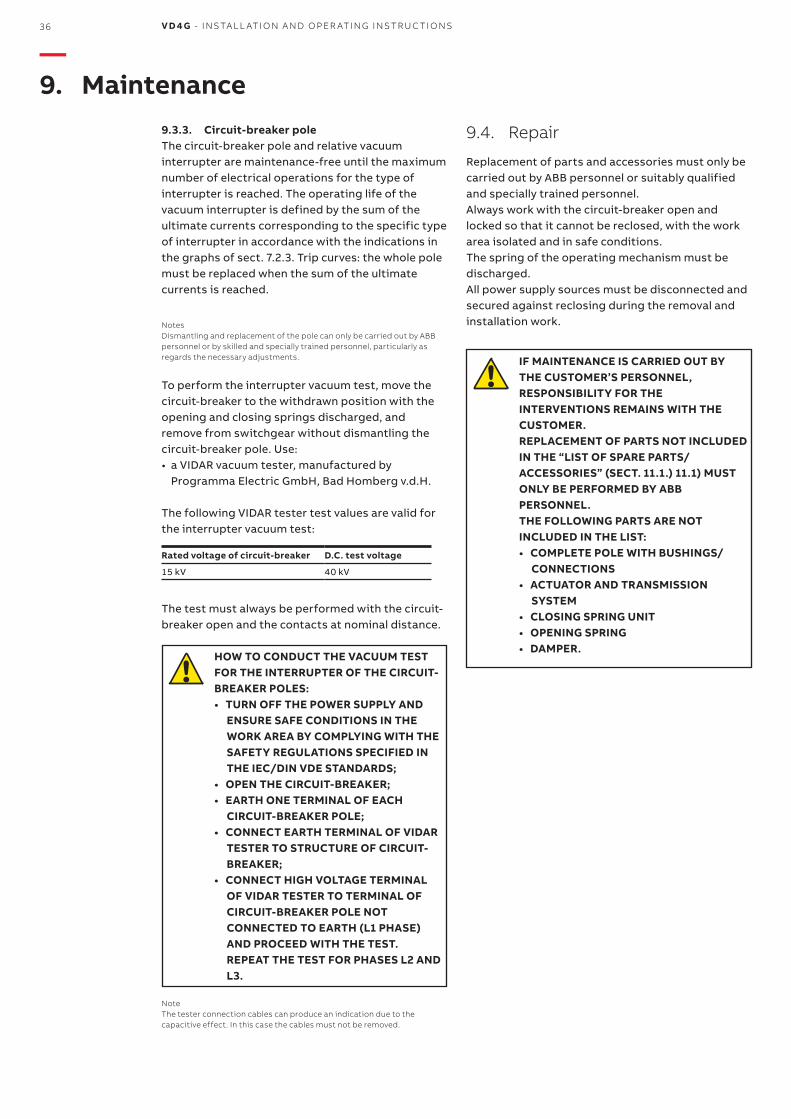
• Visual inspection of the isolating contacts. If there are tulip contacts, remember to turn them alternately in order to keep the internal surface of the conduction areas clean. The contact areas must be cleaned when there are signs of overheating (discolored surface) (also consult the Repairs section).
9.2.2. Stored energy spring operating mechanismRun a functional test on the operating mechanism test at least every 5,000 operations or 5 years, or as part of the normal maintenance operations described in sect. 9.2.1.Perform the following operations before conducting the test:• if the circuit-breaker is withdrawable, it must be
brought to the isolated for test position.• for fixed circuit-breakers: shut off the power
supplied to the medium voltage circuit.
NoteIsolate the work area and make it safe by following the safety regulations specified in standards IEC/DIN VDE.
—9. Maintenance
• Perform servicing if the conditions are abnormal (see Servicing sect.).
15 Nm
25 Nm
15 Nm
15 Nm
25 Nm
15 Nm
15 Nm
15 Nm
15 Nm
34 V D 4 G - INS TA L L ATI O N A N D O PER ATI N G I NS TR U C TI O NS
Functional test• Carry out a few opening and closing operations
with the circuit-breaker disconnected from the load.
• If required, cut off the power supply to the spring loading motor. Discharge the spring by closing and opening the circuit-breaker by means of the closing and opening pushbuttons.
• Visually inspect the tulip isolating contacts, sliding surfaces, etc., to make sure that they are properly lubricated.
• Make sure that the electrical and mechanical operation of the various devices is correct, especially the interlocks.
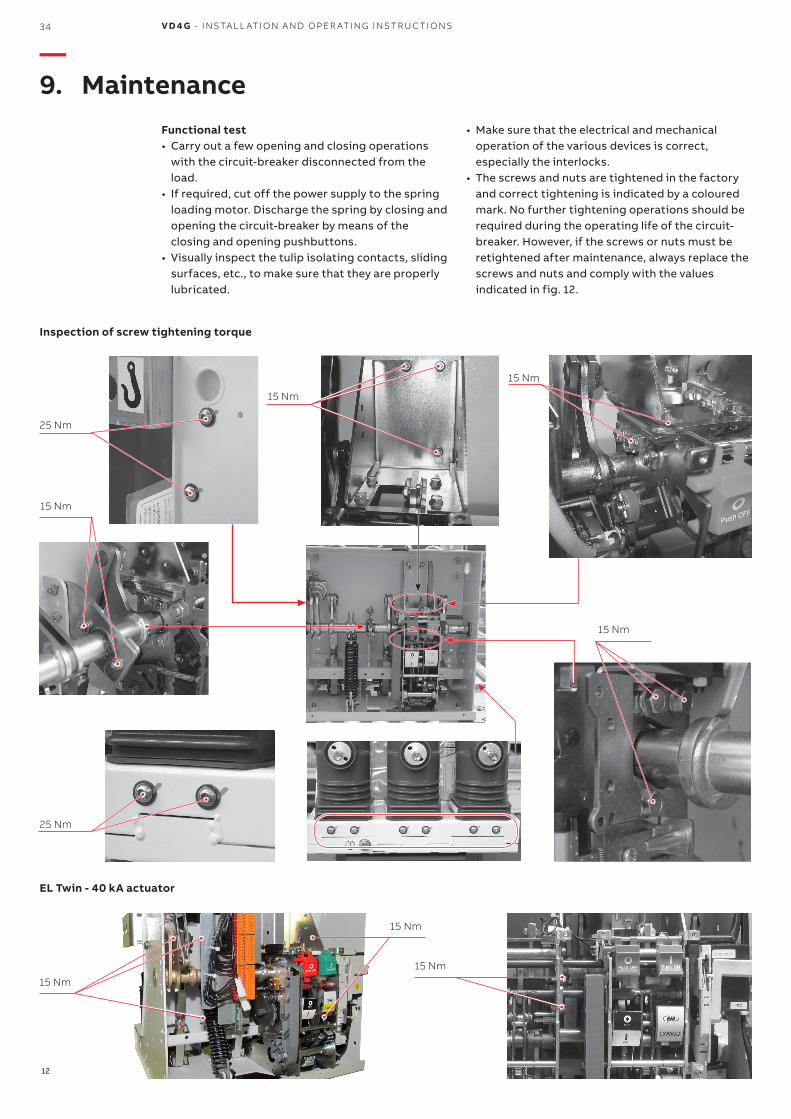
• The screws and nuts are tightened in the factory and correct tightening is indicated by a coloured mark. No further tightening operations should be required during the operating life of the circuit-breaker. However, if the screws or nuts must be retightened after maintenance, always replace the screws and nuts and comply with the values indicated in fig. 12.
Inspection of screw tightening torque
EL Twin - 40 kA actuator
12
—9. Maintenance

M ED I U M VO LTAG E PR O D U C TS 35
9.3.2. Release devices: actuator and transmission system
Circuit-breakers up to 15 kV, 1250 A, 25 kA. Inspection and maintenance should be performed after every 5,000 operations to ensure the circuit-breaker functions correctly. Contact ABB Service.The damper and other components of the transmission system (shaft, main levers, safety rings, etc.) must be totally replaced after 10,000 operations.
Circuit-breakers up to 15 kV, 40 kA and with Twin actuator Inspection and maintenance must be performed after every 5,000 operations to ensure the circuit-breaker functions correctly. Contact ABB Service.The damper and other components of the transmission system (shaft, main levers, safety rings, etc.) must be totally replaced after 10,000 operations.
NoteDismantling and replacement of the operating mechanism (trip box) can only be carried out by ABB personnel or by skilled and specially trained personnel, particularly as regards the necessary adjustments.
Details about servicing• When required, cut off the power supply to the
spring loading motor and discharge the springs of the operating mechanism in the manual mode by closing and opening the circuit-breaker.
• Replace parts subject to mechanical stress or stress due to particular ambient conditions, (contact an ABB service center).
• Refer to maintenance instruction manual 1VCD601513 for further details.
NoteThese operations can only be carried out by ABB personnel or by skilled and specifically trained personnel.
9.2.3. Circuit-breaker poleNo further inspections are necessary beyond those already described in sect. 9.2.1.
9.2.4. Withdrawable assembly (truck and circuit-breaker)
Visually inspect the components, especially those which may have been damaged by incorrect operations (also consult chap. 8).Visually inspect the isolating contacts and clean all contact parts, especially where signs of overheating are found (also consult sect. 9.4.).Visually inspect the locks. Perform functional tests to make sure that they operate properly and activate without abnormal force - maximum 25 N (also consult the table in chap. 8).
9.3. Servicing9.3.1. Pole and conductive partsComply with the following procedure if the devices had to be cleaned during the inspections, as specified in sect. 9.2.1:• isolate the work area and make it safe, following
the safety regulations specified in standards IEC/DIN VDE;
• general cleaning of surfaces: - dry and remove light deposits of dirt with a soft
dry cloth; - more resistant dirt can be removed using slightly
alkaline domestic type detergent or Rivolta BWR 210 detergent;
• clean the insulating surfaces and conductive parts with a suitable detergent.
After cleaning, thoroughly rinse with clean water and dry carefully.Apply fresh grease if necessary.
NoteOnly use halogen-free detergents and never 1.1.1-trichloroethane, trichloroethylene or carbon tetrachloride!
36 V D 4 G - INS TA L L ATI O N A N D O PER ATI N G I NS TR U C TI O NS
9.3.3. Circuit-breaker poleThe circuit-breaker pole and relative vacuum interrupter are maintenance-free until the maximum number of electrical operations for the type of interrupter is reached. The operating life of the vacuum interrupter is defined by the sum of the ultimate currents corresponding to the specific type of interrupter in accordance with the indications in the graphs of sect. 7.2.3. Trip curves: the whole pole must be replaced when the sum of the ultimate currents is reached.
NotesDismantling and replacement of the pole can only be carried out by ABB personnel or by skilled and specially trained personnel, particularly as regards the necessary adjustments.
To perform the interrupter vacuum test, move the circuit-breaker to the withdrawn position with the opening and closing springs discharged, and remove from switchgear without dismantling the circuit-breaker pole. Use:• a VIDAR vacuum tester, manufactured by
Programma Electric GmbH, Bad Homberg v.d.H.
The following VIDAR tester test values are valid for the interrupter vacuum test:
Rated voltage of circuit-breaker D.C. test voltage
15 kV 40 kV
The test must always be performed with the circuit-breaker open and the contacts at nominal distance.
HOW TO CONDUCT THE VACUUM TEST FOR THE INTERRUPTER OF THE CIRCUIT-BREAKER POLES:
• TURN OFF THE POWER SUPPLY AND ENSURE SAFE CONDITIONS IN THE WORK AREA BY COMPLYING WITH THE SAFETY REGULATIONS SPECIFIED IN THE IEC/DIN VDE STANDARDS;
• OPEN THE CIRCUIT-BREAKER; • EARTH ONE TERMINAL OF EACH
CIRCUIT-BREAKER POLE; • CONNECT EARTH TERMINAL OF VIDAR
TESTER TO STRUCTURE OF CIRCUIT-BREAKER;
• CONNECT HIGH VOLTAGE TERMINAL OF VIDAR TESTER TO TERMINAL OF CIRCUIT-BREAKER POLE NOT CONNECTED TO EARTH (L1 PHASE) AND PROCEED WITH THE TEST. REPEAT THE TEST FOR PHASES L2 AND L3.
NoteThe tester connection cables can produce an indication due to the capacitive effect. In this case the cables must not be removed.
9.4. Repair
Replacement of parts and accessories must only be carried out by ABB personnel or suitably qualified and specially trained personnel.Always work with the circuit-breaker open and locked so that it cannot be reclosed, with the work area isolated and in safe conditions.The spring of the operating mechanism must be discharged.All power supply sources must be disconnected and secured against reclosing during the removal and installation work.
IF MAINTENANCE IS CARRIED OUT BY THE CUSTOMER’S PERSONNEL, RESPONSIBILITY FOR THE INTERVENTIONS REMAINS WITH THE CUSTOMER.
REPLACEMENT OF PARTS NOT INCLUDED IN THE “LIST OF SPARE PARTS/ACCESSORIES” (SECT. 11.1.) 11.1) MUST ONLY BE PERFORMED BY ABB PERSONNEL.
THE FOLLOWING PARTS ARE NOT INCLUDED IN THE LIST:
• COMPLETE POLE WITH BUSHINGS/CONNECTIONS
• ACTUATOR AND TRANSMISSION SYSTEM
• CLOSING SPRING UNIT • OPENING SPRING • DAMPER.
—9. Maintenance

M ED I U M VO LTAG E PR O D U C TS 37
—10. Application of the X-ray emission Standards
One of the physical properties of vacuum insulation is that X-rays could be emitted. The specific tests performed at the PTB laboratories (Physikalisch-Technische Bundesanstalt, in Brunswick - Germany) show that local emission at a distance of 10 cm from the interrupter or pole surface, does not exceed 1 mSv/h.This means that:• use of vacuum interrupters is absolutely safe at
rated service voltage;• application of withstand voltage at power
frequency (according to the IEC 62271-100 and VDE 0670
• standards) is safe;• voltage higher than the withstand voltage at
power frequency or than a direct current test voltage (specified in the IEC and VDE standards) cannot be applied;
• in interrupters with open contacts, limitation of the above-mentioned local phenomena depends on maintaining the specific gap between contacts.
This condition is intrinsically guaranteed by correct operation of the operating mechanism and by the settings of the transmission system.
38 V D 4 G - INS TA L L ATI O N A N D O PER ATI N G I NS TR U C TI O NS
—11. Spare parts and accessories
ALL ASSEMBLY OPERATIONS OF SPARE PARTS/ACCESSORIES MUST BE CARRIED OUT IN ACCORDANCE WITH THE INSTRUCTIONS ENCLOSED ALL ASSEMBLY OPERATIONS OF SPARE PARTS/ACCESSORIES MUST BE CARRIED OUT IN ACCORDANCE WITH THE INSTRUCTIONS ENCLOSED WITH THE SPARE PARTS THEMSELVES, BY ABB PERSONNEL OR BY SUITABLY QUALIFIED CUSTOMER PERSONNEL WITH IN-DEPTH KNOWLEDGE OF THE APPARATUS (IEC 62271-100) AND OF ALL THE STANDARDS AIMED AT ENSURING THAT THESE INTERVENTIONS ARE CARRIED OUT IN SAFE CONDITIONS. IF MAINTENANCE IS CARRIED OUT BY THE CUSTOMER’S PERSONNEL, RESPONSIBILITY FOR THE INTERVENTIONS REMAINS WITH THE CUSTOMER. BEFORE PROCEEDING WITH ANY OPERATION, ALWAYS MAKE SURE THAT THE CIRCUIT-BREAKER IS OPEN, THE CLOSING AND OPENING SPRINGS DISCHARGED AND NOT ENERGIZED (MEDIUM VOLTAGE CIRCUIT AND AUXILIARY CIRCUITS).
When ordering spare parts/accessories for the circuit-breaker, refer to the ordering codes indicated in the technical catalog and always state the following: • type of circuit-breaker • rated voltage of circuit-breaker • rated thermal current of circuit-breaker • breaking capacity of circuit-breaker • serial number of circuit-breaker • rated voltage of any electrical spare parts.
Please contact our Service office to check on availability and to order spare parts.
11.1. List of spare parts
• Shunt opening release• Additional shunt opening release• Spring loading gearmotor with electrical signaling
of springs loaded• Contact for signaling gearmotor protection
circuit-breaker open/closed• Contact for signaling closing spring loaded/
discharged• Transient contact with momentary closing during
circuit-breaker opening. • Auxiliary contacts of circuit-breaker • Locking electromagnet on operating mechanism• Position contact of withdrawable truck• Connected/isolated signaling contacts • Door isolating interlock • Locking electromagnet on withdrawable truck • Set of six tulip contacts • Shunt closing releasea
M ED I U M VO LTAG E PR O D U C TS 39
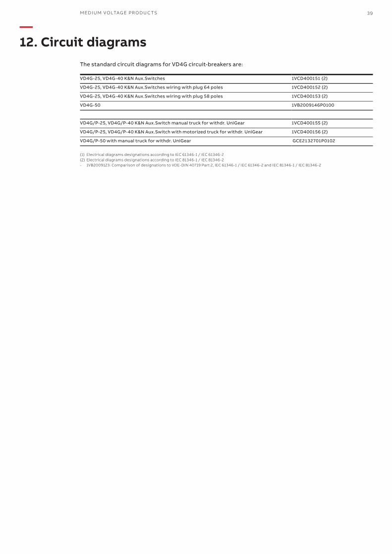
—12. Circuit diagrams
The standard circuit diagrams for VD4G circuit-breakers are:
VD4G-25, VD4G-40 K&N Aux.Switches 1VCD400151 (2)
VD4G-25, VD4G-40 K&N Aux.Switches wiring with plug 64 poles 1VCD400152 (2)
VD4G-25, VD4G-40 K&N Aux.Switches wiring with plug 58 poles 1VCD400153 (2)
VD4G-50 1VB2009146P0100
VD4G/P-25, VD4G/P-40 K&N Aux.Switch manual truck for withdr. UniGear 1VCD400155 (2)
VD4G/P-25, VD4G/P-40 K&N Aux.Switch with motorized truck for withdr. UniGear 1VCD400156 (2)
VD4G/P-50 with manual truck for withdr. UniGear GCE2132701P0102
(1) Electrical diagrams designations according to IEC 61346-1 / IEC 61346-2(2) Electrical diagrams designations according to IEC 81346-1 / IEC 81346-2- 1VB2009123: Comparison of designations to VDE-DIN 40719 Part 2, IEC 61346-1 / IEC 61346-2 and IEC 81346-1 / IEC 81346-2
531
503
19
14
619
492 233 43
626
627
10
64
29
23
123
437
382
34 25
320
573 ±1,5 max
610
662
37
21,
5
296
10
0
78
205
±1
260
±1
154
±1 7
8
121
110
302
4
150 ±1 150 ±1
341 468 492 500
Type U I I System Source I Generator Source I Out-of-Phase O.M Cubible
VD4G/P-25 15 kV 1250A 25 kA 16/ 16 kA 12.5 kA EL UNIGEAR ZS1 W=650
636
44,5 220 25
19
12,
5
14 605 653 14 4
6
89
320 25
302
359
590 382
52
21
,5
19
,5
76
165
310
2
81
698
11
9
119
10
37
110 123
642
23
314
20
26
16
4
11
210 210
29
359
590
302
550 626 640 650
C.B Type U In Isc/ Iscg/ Id O.M Execution
VD4G-40 15 kV 2000A 40 kA/ 25kA/ 20kA EL1 Twin Unigear Powercube
40 V D 4 G - INS TA L L ATI O N A N D O PER ATI N G I NS TR U C TI O NS
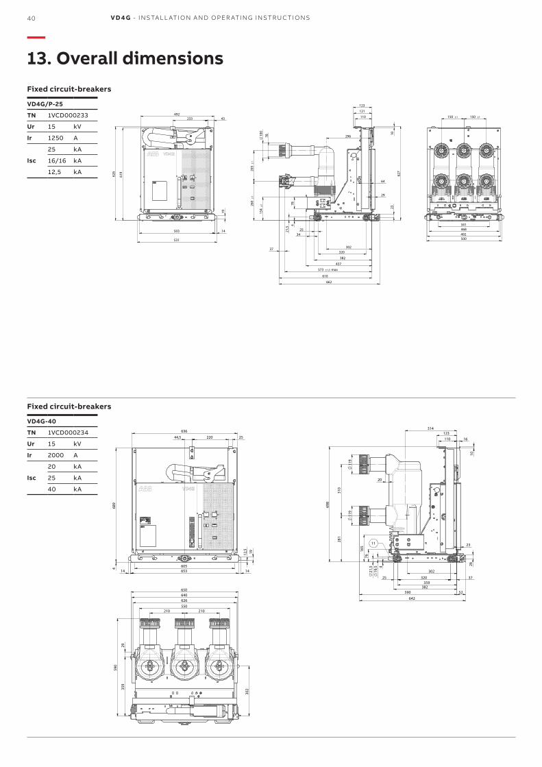
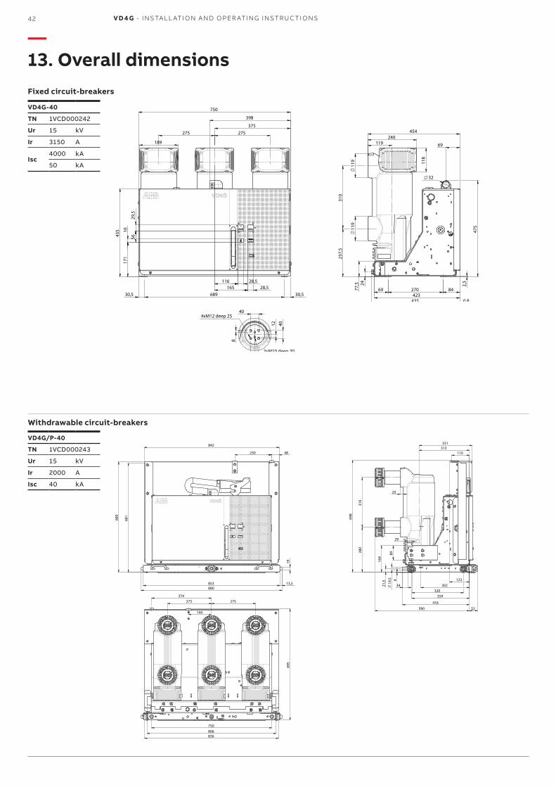
—13. Overall dimensionsFixed circuit-breakers
Fixed circuit-breakers
VD4G/P-25
TN 1VCD000233
Ur 15 kV
Ir 1250 A
Isc
25 kA
16/16 kA
12,5 kA
VD4G-40
TN 1VCD000234
Ur 15 kV
Ir 2000 A
Isc
20 kA
25 kA
40 kA
171
1
6
56 4
35
323 600
30
97
15
48 504 48
28,5 28,5 368
210 210
475
32
310
436 1 424
172 142 109
77,
5
24
609
237
,5
2,5
130
11
9
119
1112
20
40
24
4xM12 Deep .25
2xM10 Deep .18
8
C.B. Type U In Iss O.M Execution
VD4G-40 15 kV 2000 A 50 kA EL1 Twin Unigear Powercube
750 396
634 58
429 28,5
28,5 49
30
16
56
15
97
435
171
275 275
3
11
9
119
474
440 0,8
32
69 270 84
424
609
2
38
310
77,
5
119 99
24
40
40
24
20 98
M12 Deep .25
M10 Deep .18
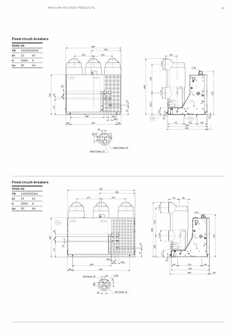
M ED I U M VO LTAG E PR O D U C TS 41
VD4G-40
TN 1VCD000240
Ur 15 kV
Ir 2000 A
Isc 50 kA
VD4G-40
TN 1VCD000241
Ur 15 kV
Ir 2000 A
Isc 50 kA
Fixed circuit-breakers
Fixed circuit-breakers
750
398
375
189
689 30,5 30,5
171
1
6
56
29,
5
435
116 28,5 165 28,5
275 275
32
475
69 270 84 423
435 0,8
24
77,
5
119
11
9
310
2
37,5
119 240
454
69
2,5
118
40
40
20
8
4xM12 deep 25
2xM10 deep 20
12
C.B. Type U In Iss O.MVD4G-40 15 kV 3150/4000 A 50 kA EL2 Twin
880 853
19
13,5
842
230 48
689
681
695
374
144
275 275
750 806 836
310
2
80
29
89
359
302 123
110
416
590
164
19
,5
21,
5
320 34
52
331 313
698
20
4
C.B Type U In Iss O.M Execution
VD4G/P-40 15 kV 2000 A 40kA EL1 Twin UnigearPowercube
42 V D 4 G - INS TA L L ATI O N A N D O PER ATI N G I NS TR U C TI O NS
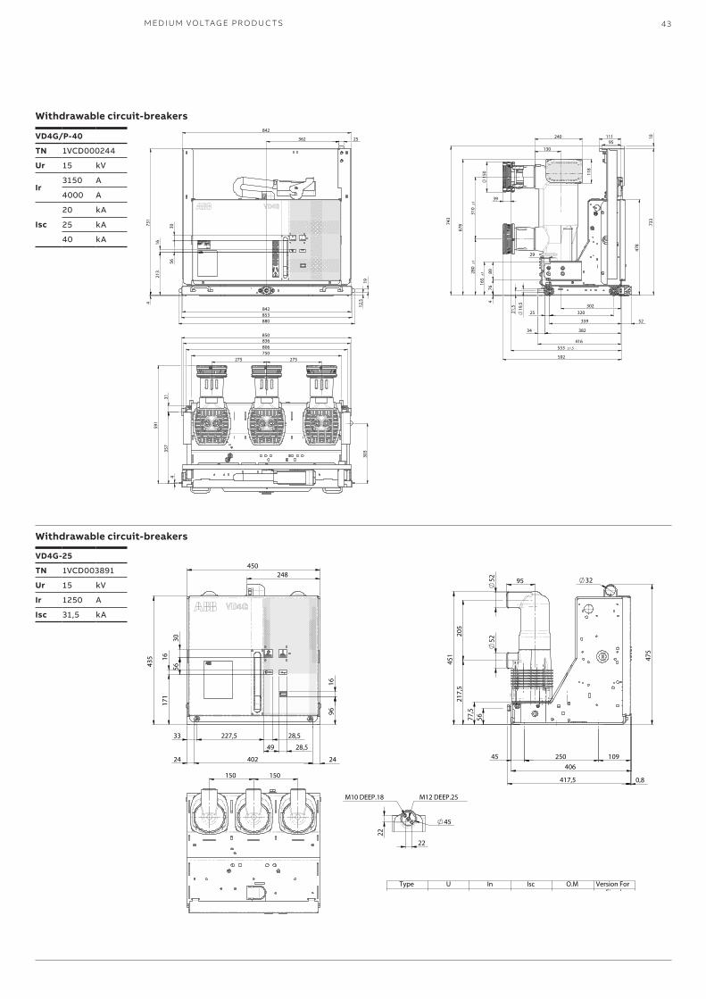
VD4G-40
TN 1VCD000242
Ur 15 kV
Ir 3150 A
Isc4000 kA
50 kA
VD4G/P-40
TN 1VCD000243
Ur 15 kV
Ir 2000 A
Isc 40 kA
Fixed circuit-breakers
Withdrawable circuit-breakers
—13. Overall dimensions
450 248
96
16
33 227,5 28,5
49 28,5
435
171
1
6
56
30
24 402 24
150 150
451
2
05
217
,5
77,
5 5
6
406
475
32 95
250
417,5 0,8
45 109
52
52
M12 DEEP.25
22
22
M10 DEEP.18
45
Type U In Isc O.M Version For
VD4G-25 15 kV 1250A 31.5kA EL Fixed Installation
842
880 853
19
12,
5
25 362
842
213
1
6
56
30 7
31
4
280
±1
21,
5
19
,5
320 25
592
416
34 382
359
302
111 95
310
±1
678
165
±1 8
9
29
52
743
130
240
118
10
733
478
39
76
15
0
553 ±1,5
4
275 275
836 850
806
591
357
3
1
750
4
303
C.B Type U In I System Source I Generator Source I Out-of-Phase O.M Cubicle
VD4G/P-4015 kV
3150A40kA 25kA 20kA EL
UNIGEAR ZS1 W=1000
VD4G/P-40 4000A UNIGEAR ZS1 W=1000
M ED I U M VO LTAG E PR O D U C TS 43
Withdrawable circuit-breakers
Withdrawable circuit-breakers
VD4G/P-40
TN 1VCD000244
Ur 15 kV
Ir3150 A
4000 A
Isc
20 kA
25 kA
40 kA
VD4G-25
TN 1VCD003891
Ur 15 kV
Ir 1250 A
Isc 31,5 kA

44 V D 4 G - INS TA L L ATI O N A N D O PER ATI N G I NS TR U C TI O NS
—14. Quality of the products and environmental protection
The apparatus is manufactured in accordance with the requirements established by the international standards concerning quality management and environmental management systems. The level of excellence in these fields is testified by the ISO 9001 and ISO 14001 certificates available.
End of life of the productsABB undertakes to comply with the environmental protection requirements laid down by law, in accordance with the provisions established by the ISO 14001 standards.ABB provides skills and assistance to facilitate the recycling and disposal process for products at the end of their life. Compliance with the local regulations when disposing of products is always mandatory.
Disposal methods
The products can be disposed of by means of heat treatments, in incineration systems or by storage in dedicated areas.
Material Recommended disposal method
Metals (Fe, Cu, Al, Ag, Zn, W, other)
Separation and recycling
Thermoplastics Recycling or disposal, separation of metal parts
Epoxy resin Separation of metal parts, disposal of resin parts
Rubber Disposal
Wood for packaging Recovery, recycling and/or disposal
Sheets of polyethylene or paper for packaging
Recycling or disposal

M ED I U M VO LTAG E PR O D U C TS 45
—Notes
. . . . . . . . . . . . . . . . . . . . . . . . . . . . . . . .
. . . . . . . . . . . . . . . . . . . . . . . . . . . . . . . .
. . . . . . . . . . . . . . . . . . . . . . . . . . . . . . . .
. . . . . . . . . . . . . . . . . . . . . . . . . . . . . . . .
. . . . . . . . . . . . . . . . . . . . . . . . . . . . . . . .
. . . . . . . . . . . . . . . . . . . . . . . . . . . . . . . .
. . . . . . . . . . . . . . . . . . . . . . . . . . . . . . . .
. . . . . . . . . . . . . . . . . . . . . . . . . . . . . . . .
. . . . . . . . . . . . . . . . . . . . . . . . . . . . . . . .
. . . . . . . . . . . . . . . . . . . . . . . . . . . . . . . .
. . . . . . . . . . . . . . . . . . . . . . . . . . . . . . . .
. . . . . . . . . . . . . . . . . . . . . . . . . . . . . . . .
. . . . . . . . . . . . . . . . . . . . . . . . . . . . . . . .
. . . . . . . . . . . . . . . . . . . . . . . . . . . . . . . .
. . . . . . . . . . . . . . . . . . . . . . . . . . . . . . . .
. . . . . . . . . . . . . . . . . . . . . . . . . . . . . . . .
. . . . . . . . . . . . . . . . . . . . . . . . . . . . . . . .
. . . . . . . . . . . . . . . . . . . . . . . . . . . . . . . .
. . . . . . . . . . . . . . . . . . . . . . . . . . . . . . . .
. . . . . . . . . . . . . . . . . . . . . . . . . . . . . . . .
. . . . . . . . . . . . . . . . . . . . . . . . . . . . . . . .
. . . . . . . . . . . . . . . . . . . . . . . . . . . . . . . .
. . . . . . . . . . . . . . . . . . . . . . . . . . . . . . . .
. . . . . . . . . . . . . . . . . . . . . . . . . . . . . . . .
. . . . . . . . . . . . . . . . . . . . . . . . . . . . . . . .
. . . . . . . . . . . . . . . . . . . . . . . . . . . . . . . .
. . . . . . . . . . . . . . . . . . . . . . . . . . . . . . . .
. . . . . . . . . . . . . . . . . . . . . . . . . . . . . . . .
. . . . . . . . . . . . . . . . . . . . . . . . . . . . . . . .
. . . . . . . . . . . . . . . . . . . . . . . . . . . . . . . .
. . . . . . . . . . . . . . . . . . . . . . . . . . . . . . . .
. . . . . . . . . . . . . . . . . . . . . . . . . . . . . . . .
. . . . . . . . . . . . . . . . . . . . . . . . . . . . . . . .
. . . . . . . . . . . . . . . . . . . . . . . . . . . . . . . .
. . . . . . . . . . . . . . . . . . . . . . . . . . . . . . . .
. . . . . . . . . . . . . . . . . . . . . . . . . . . . . . . .
. . . . . . . . . . . . . . . . . . . . . . . . . . . . . . . .
. . . . . . . . . . . . . . . . . . . . . . . . . . . . . . . .

—More product information:www.abb.com/mediumvoltageYour contact center:www.abb.com/contactcentersMore service information:www.abb.com/service
1VC
D6
014
73 -
Rev
. B, e
n -
Inst
ruct
ion
Man
ual
- 2
017
.12
(VD
4G
) (g
s)
Data and illustration are not binding. We reserve the right to make changes in the course of technical development.
© Copyright 2017 ABB. All rights reserved.
—For more information please contact: