Embed Size (px)
Citation preview
Installation- and Operating instructions for
USB-Extender-Rx CU8850-0000
Version: 1.2 Date: 2015-03-25

Table of contents
Table of contents 1.
2.
3.
4.
5.
General instructions 2 Notes on the Documentation 2 Liability Conditions 2 State at Delivery 2 Description of safety symbols 2
Product Description 3 Product Overview 3 Power supply 4 UL requirements 4 Data Connectors 4
RJ 45 Port (X20) (standard CAT5-cable) 4 USB Typ A Port (X30) (standard-cable) 4
LED Diagnostics 5 Installation Instructions 6
Transport and Unpacking 6 Transport 6 Unpacking 6
Mounting/ Unmounting 7 Connecting devices 8
Connecting cables 8 Check voltage rating and connect 8
Operating Instructions 9 Architecture Description 9
Appendix 10 Assembly dimensions 10 Beckhoff Support & Service 11
Beckhoff branches and partner companies 11 Beckhoff Headquarters 11 Beckhoff Support 11 Beckhoff Service 11
Technical data 12 Approvals for USA and Canada 12
FCC: Federal Communications Commission Radio Frequency Interference Statement 12 FCC: Canadian Notice 12
CU8850-0000 1
General instructions
General instructions
Notes on the Documentation This description is only intended for the use of trained specialists in control
and automation engineering who are familiar with the applicable national standards. It is essential that the following notes and explanations are followed when installing and commissioning these components.
Liability Conditions
The responsible staff must ensure that the application or use of the products described satisfy all the requirements for safety, including all the relevant laws, regulations, guidelines and standards.
The documentation has been prepared with care. The products described are, however, constantly under development. For that reason the documentation is not in every case checked for consistency with performance data, standards or other characteristics. None of the statements of this manual represents a guarantee (Garantie) in the meaning of § 443 BGB of the German Civil Code or a statement about the contractually expected fitness for a particular purpose in the meaning of § 434 par. 1 sentence 1 BGB. In the event that it contains technical or editorial errors, we retain the right to make alterations at any time and without warning. No claims for the modification of products that have already been supplied may be made on the basis of the data, diagrams and descriptions in this documentation.
© This documentation is copyrighted. Any reproduction or third party use of this publication, whether in whole or in part, without the written permission of Beckhoff Automation GmbH & Co. KG, is forbidden.
State at Delivery
All the components are supplied in particular hardware and software configurations appropriate for the application. Modifications to hardware or software configurations other than those described in the documentation are not permitted, and nullify the liability of Beckhoff Automation GmbH & Co. KG.
Description of safety symbols
The following safety symbols are used in this operating manual. They are intended to alert the reader to the associated safety instructions.
Danger
This symbol is intended to highlight risks for the life or health of personnel.
Warning
This symbol is intended to highlight risks for equipment, materials or the environment.
i Note
This symbol indicates information that contributes to better understanding.
2 CU8850-0000

Product Description
Product Description
Product Overview View of the CU8850-0000 USB-Extender-Rx
The USB specification allows a distance of 5 m between the PC and the USB devices. A further 5 metres of cable can be added by using a USB hub. In the construction of machines and plants, larger distances must be bridged without having to insert a USB hub every 5 metres. The CU8800 USB Extender sends the USB signal via a CAT5 cable that can be up to 50 m long to the CU8850 USB Extended receiver, which converts the signal back to USB. Data rates of up to 12 Mbit/s can be transmitted. Both USB Extender boxes are designed for DIN rail mounting.
Other outstanding features are:
• user-friendly installation via integrated top hat rail adapter • 24 VDC supply voltage – the standard in industrial evironments • 12 Mbit, and 1.5 Mbit support for compatibility to all USB1.1
standards • standard CAT5 network cable for extension • compact industrial design • clear quick diagnosis by separate LEDs for power supply in and
out
CU8850-0000 3

Product Description
Power supply Additional 24 VDC power supply Normally the USB-Extender-Rx CU8850 is
powered via the USB-extension. The device can also be powered by an additional power supply (X10).
If a USB device needs more than the specified max. of 300mA, the additional power supply must be connected.
The pins have to be connected as shown on the front panel of the CU8850-device.
Power Supply
UL requirements
For the compliance of the UL requirements the USB-Extender-Rx should only be supplied
• by a 24 VDC supply voltage, supplied by an isolating source and protected by means of a fuse (in accordance with UL248), rated maximum 4 Amp.
• by a 24 VDC power source, that has to satisfy NEC class 2. A class 2 power supply shall not be connected in series or parallel with another (class 2) power source!
Danger
To meet the UL requirements, the USB hub CU8800-0000 must not be connected to unlimited power sources!
Data Connectors The CU8850 has two kinds of connectors: RJ45 and USB type A. The
pin layouts are described below.
RJ 45 Port (X20) (standard CAT5-cable) RJ 45 Port
Pin Signal Belegung
USB Typ A
USB Typ A Port
P
X20
4 3 2 1
SX30
4
in 1
1 15 V 15 V + 2 GND GND Pin 8 3 TX USB TX 4 RX USB RX 5 RX USB RX 6 TX USB TX 7 15 V 15 V + 8 GND GNDPort (X30) (standard-cable)
Pin Signal
1 VCC 2 Data - 3 Data + 4 GND hieldShield Shield
CU8850-0000

Product Description
LED Diagnostics LED Diagnostics
The following table shows the possible states for the LEDs:
LED Assignment Status Meaning off No power supply connected P10 Power Supply lights green 24 VDC connected Off USB is operational P20 USB Suspend
Lights USB is in suspend mode/ no device connected
Off No 15 V supplied P21 USB 15 V Lights 15 V supplied to USB extension Off Full-speed device connected P22 USB Device
Full-Speed Lights No device connected Off Low-speed device connected P23 USB Device
Low-Speed Lights No device connected lights green Current < 500 mA P30 Current load at
USB Port lights red Current > 500 mA
P30
P23 P22
P21
P20
P10
CU8850-0000 5

Installation Instructions
Installation Instructions Please also refer to chapter General instructions.
Transport and Unpacking The specified storage conditions must be observed (see chapter Technical
data).
Transport Despite the robust design of the unit, the components are sensitive to
strong vibrations and impacts. During transport, the unit should therefore be protected from excessive mechanical stress. Therefore, please use the original packaging.
Warning
Danger of damage to the unit! If the device is transported in cold weather or is exposed to extreme variations in temperature, make sure that moisture (condensation) does not form on or inside the device. Prior to operation, the unit must be allowed to slowly adjust to room temperature. Should condensation occur, a delay time of approximately 12 hours must be allowed before the unit is switched on.
Unpacking
Proceed as follows to unpack the unit:
1. Remove packaging. 2. Do not discard the original packaging. Keep it for future relocation. 3. Check the delivery for completeness by comparing it with your order. 4. Please keep the associated paperwork. It contains important
information for handling the unit. 5. Check the contents for visible shipping damage. 6. If you notice any shipping damage or inconsistencies between the
contents and your order, you should notify Beckhoff Service.
6 CU8850-0000
Installation Instructions
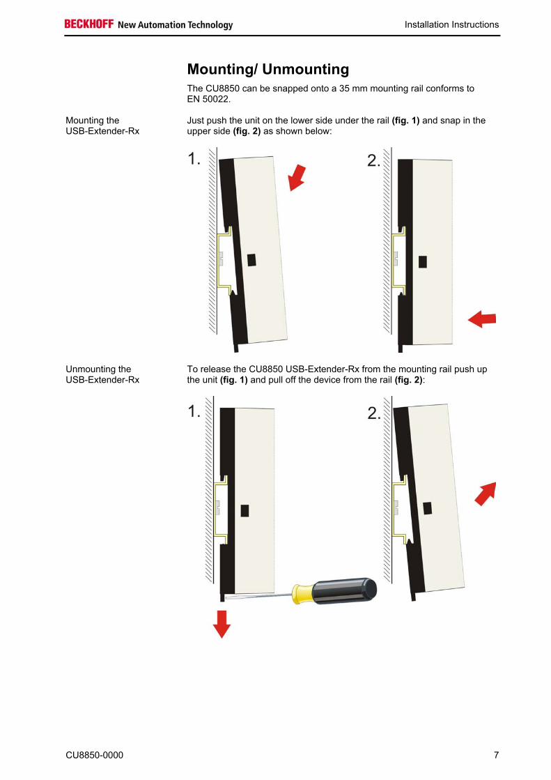
Mounting/ Unmounting The CU8850 can be snapped onto a 35 mm mounting rail conforms to
EN 50022.
Mounting the USB-Extender-Rx
Just push the unit on the lower side under the rail (fig. 1) and snap in the upper side (fig. 2) as shown below:
Unmounting the USB-Extender-Rx
To release the CU8850 USB-Extender-Rx from the mounting rail push up the unit (fig. 1) and pull off the device from the rail (fig. 2):
CU8850-0000 7

Installation Instructions
Connecting devices
Warning
The power supply plug must be withdrawn! Please read the documentation for the external devices prior to connecting them. During thunderstorms, plug connector must neither be inserted nor removed. When disconnecting a plug connector, always handle it at the plug. Do not pull the cable!
Connecting cables
The connectors are documented in the section Product Description. When connecting the cables to the CU8850 USB-Extender-RX, proceed according to the following sequence:
• Switch off all the devices that are to be connected. • Disconnect all the devices that are to be connected from the power
supply. • Connect all the cables between the CU8850 and to the devices
that are to be connected. • Reconnect all devices to the power supply.
Check voltage rating and connect
1. Check that the external power supply is providing the correct voltage.
2. Connect the unit to your external 24 VDC power supply.
8 CU8850-0000
Operating Instructions
Operating Instructions
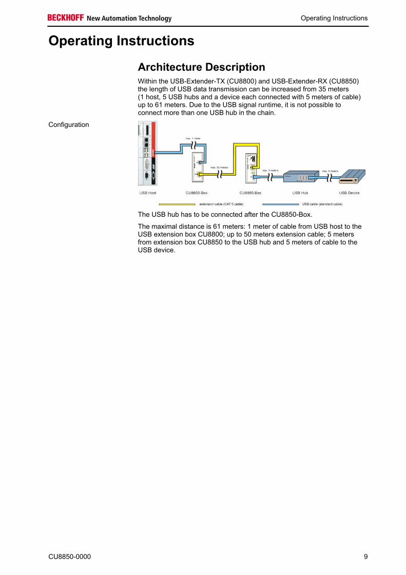
Architecture Description Within the USB-Extender-TX (CU8800) and USB-Extender-RX (CU8850)
the length of USB data transmission can be increased from 35 meters (1 host, 5 USB hubs and a device each connected with 5 meters of cable) up to 61 meters. Due to the USB signal runtime, it is not possible to connect more than one USB hub in the chain.
Configuration
The USB hub has to be connected after the CU8850-Box.
The maximal distance is 61 meters: 1 meter of cable from USB host to the USB extension box CU8800; up to 50 meters extension cable; 5 meters from extension box CU8850 to the USB hub and 5 meters of cable to the USB device.
CU8850-0000 9
Appendix
Appendix
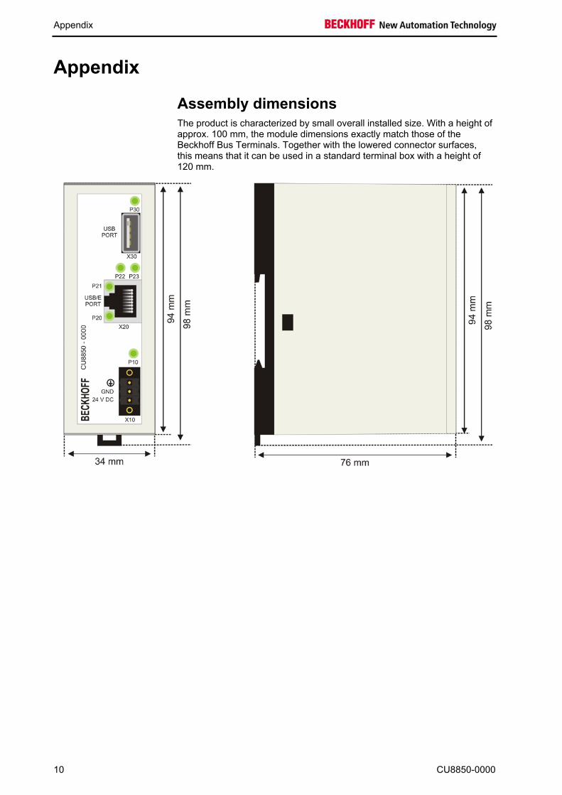
Assembly dimensions
The product is characterized by small overall installed size. With a height of approx. 100 mm, the module dimensions exactly match those of the Beckhoff Bus Terminals. Together with the lowered connector surfaces, this means that it can be used in a standard terminal box with a height of 120 mm.
10 CU8850-0000

Appendix
Beckhoff Support & Service Beckhoff and their partners around the world offer comprehensive support
and service, guaranteeing fast and competent assistance with all questions related to Beckhoff products and system solutions.
Beckhoff branches and partner companies Please contact your Beckhoff branch office or partner company for local support and service on Beckhoff products!
The contact addresses for your country can be found in the list of Beckhoff branches and partner companies: www.beckhoff.com You will also find further documentation for Beckhoff components there.
Beckhoff Headquarters Beckhoff Automation GmbH & Co. KG Huelshorstweg 20 33415 Verl Germany Phone: +49(0)5246/963-0 Fax: +49(0)5246/963-198 e-mail: [email protected]
Beckhoff Support Beckhoff offers you comprehensive technical assistance, helping you not only with the application of individual Beckhoff products, but also with wide-ranging services:
• worldwide support • design, programming and commissioning of complex automation
systems • training program for Beckhoff system components
Hotline: +49(0)5246/963-157 Fax: +49(0)5246/963-9157 e-mail: [email protected]
Beckhoff Service The Beckhoff service center supports you in all matters of after-sales service:
• on-site service • repair service • spare parts service • hotline service
Hotline: +49(0)5246/963-460 Fax: +49(0)5246/963-479 e-mail: [email protected]
Quote the project number If servicing is required, please quote the project number of your product.
CU8850-0000 11

Appendix
12 CU8850-0000
Technical data Number of ports USB Type A ports (upstream): 1 USB Extender Rx ports (RJ45): 1 Supported standard USB 1.1 Supported baud rates 12 Mbit (Full Speed), 1.5 Mbit (Low Speed) Status display 2 LEDs USB extension wiring length
Maximum 50 meters
USB wiring length Maximum 5 meters Additional Power supply 24 VDC (-15% to +20%), protected against polarity reversal.
To meet the UL requirements use 4 A fuse or class 2 power supply! Power output (USB) Maximum 300 mA (without additional power supply)
Maximum 500 mA (with connected additional power supply) Power consumption device Maximum 500 mW
The following conditions must be observed during operation: Environmental conditions Ambient temperature: 0 to 55°C (operation)
-25°C to +70°C (transport/ storage) Atmospheric humidity: Maximum 95%, non-condensing
Vibration/ Shock resistance EN 60068-2-6 / EN 60068-2-27 EMC resistance burst/ ESD EN 60000-6-2 / EN 60000-6-4 Protection class IP20
Do not use the CU8850 in areas of explosive hazard
The DVI splitter may not be used in areas of explosive hazard.
Dimensions (W x H x D) Approx. 34 mm x 100 mm x 76 mm (with mounting for DIN rail) Weight Approx. 95 g Assembly On 35 mm mounting rail conforms to EN 50022 Installation position Any Approvals CE
UL (for details see chapter UL requirements)
Approvals for USA and Canada
FCC: Federal Communications Commission Radio Frequency Interference Statement
FCC Approval for USA This equipment has been tested and found to comply with the limits for a Class A digital device, pursuant to Part 15 of the FCC Rules. These limits are designed to provide reasonable protection against harmful interference when the equipment is operated in a commercial environment. This equipment generates, uses, and can radiate radio frequency energy and, if not installed and used in accordance with the instruction manual, may cause harmful interference to radio communications. Operation of this equipment in a residential area is likely to cause harmful interference in which case the user will be required to correct the interference at his own expense.
FCC: Canadian Notice FCC Approval for Canada This equipment does not exceed the Class A limits for radiated emissions as
described in the Radio Interference Regulations of the Canadian Department of Communications.