Embed Size (px)
Citation preview

DESCRIPTION
OPERATIONS
Model AOPSP-PB is a wall mount two-way call stations containing a built-in line level electret condenser microphone, a 4”(101mm) speaker and a 1”(25.4mm) call button. It is designed to interface with various modes of audio/video transmission systems such as:
IP Network CamerasDVR’sVideo ServersPC Soundcards
Provided with the unit are two back boxes for either flush or surface mounting to a wall. The AOPSP-PB can be used as a stand alone unit or with companion AOP-XD. The AOP-XD Audio Transceiver Interface unit provides two-way audio with the receiving device (IP Network Camera, etc.). Also, a built-in 1” (25.4mm) call button for provides switch closure activation with the receiving device.
The AOP-XD provides power to the AOPSP-PB Speakerphone and drives the audio signals (line level) into the audio input of the above receiving devices. It also receives the return audio signals from the “Audio Out” or “Speaker Out” of the DVR, etc. and amplifies the output level for broadcasting through the speaker portion of the AOPSP-PB Speakerphone. AOP-XD contains adjustable audio level controls for listen and talkback. Located on the back panel of the AOP-XD are two RCA audio input and output jacks for accommodating most DVR’s, IP Network Camera’s audio inputs etc. When the AOPSP-PB is used as a standalone unit, a 12Vdc power supply is needed.
Model AOPSP-PB
is for flush or surfacemounting to a wall or flat surface
Back Boxes
Flush Mount(Plastic)
Surface Mount(Steel)
The gain of the microphone and speaker are factory adjusted. If it is necessary to change the gain of either or both the audio output of the microphone and speaker of the unit, it has to be done in small increments. For adjusting the gain of the microphone, rotate clockwise to increase or counterclockwise to decrease, the potentiometer marked “MIC” slowly until the desired level is attained. Somebody at the head-end has to listen to it while the adjustments are made. If the microphone’s gain is too high, it will attenuate the audio output of the speaker. The output of the speaker will then be cutting off as you talk. If this happens, rotate the potentiometer marked “MIC” slowly counterclockwise to decrease the gain of the microphone until the talkback sound at the speaker no longer cuts off.
To adjust the audio output of the speaker, rotate the “SPKR” potentiometer clockwise (increase) or counterclockwise (decrease) slowly until the desired loudness is attained. If the audio from the microphone starts to get low, rotate the “SPKR” potentiometer counterclockwise a small increment at a time until the microphone audio becomes louder again.
This unit has a built-in muting system that if the microphone’s is too high it is going to mute the speaker and vice versa.
aopsp-pb 03/11Page 1 of 8
AOPSP-PBBI-DIRECTIONAL SPEAKERPHONE
INSTALLATION AND OPERATING INSTRUCTIONS6955 VALJEAN AVE, VAN NUYS, CA 91406
PH: (818)994-6498 / FAX: (818)994-6458 / [email protected]
®

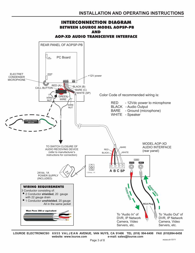
Color Code of recommended wiring is:
RED - 12Vdc power to microphoneBLACK - Audio OutputBARE - Ground (microphone)WHITE - Speaker
block marked A, B, C, SP
A = 12Vdc power (red wire)B = Audio output (black wire)C = Ground (bare wire)SP = Speaker connection (white wire)
Bring one end of recommended cable and connect as follows:
Located on the bottom right side of PC board is a 4-pin terminal
WIRING CONNECTION TO SPEAKER AND MICROPHONE OF AOPSP-PB
WIRING CONNECTION FROM AOPSP-PB TO COMPANION AOP-XD AUDIO INTERFACE UNIT
Connect the two wires (black and green) attached to Call Button Switch to the contacts of thereceiving device, using wire nuts and 22 gauge stranded wire. Refer to the receiving device manufacturers instructions for proper connection.
The rear panel of AOP-XD has a 4 pin terminal block marked A, B, C, SP
Bring in other end and connect as follows:
1) Red wire to terminal A2) Black wire to terminal B3) Bare wire to terminal C4) White wire to terminal SP
APPLYING POWER TO MODEL AOP-XD
Included with the AOP-XD is a 24V, 1A Power Supply. First connect small end to the 24Vdc jack located on the back panel of AOP-XD. Then plug large 2-prong power block into a standard 120V electrical outlet or power strip. Green LED on front panel will illuminate, indicating unit is powered. Model AOP-XD will send power to the remote AOPSP-PB Call Station. For instructions regarding the functions of AOP-XD, refer to accompanying AOP-XD instructions.
1) Connect RED wire to terminal marked “A”2) Connect BLA CK wire to terminal marked “B”3) Connect BARE wire to terminal marked “C “4) Connect WHITE wire to terminal marked “SP “
WIRING REQUIREMENTS 3 Conductor consisting of:
+2 Conductor shielded, 20 gauge with 22 gauge drain
+1 Conductor unshielded, 20 gauge All in the same jacket
Drill an opening top, bottom or back side of backbox for passing wiring or for connecting conduit
Page 2 of 8
LOUROE ELECTRONICS® 6 9 5 5 VA L J E A N AVENUE, VAN NUYS, CA 91406 TEL (818) 994-6498 FAX 994-6458website: www.louroe.com e-mail: [email protected]
(818)
INSTALLATION AND OPERATING INSTRUCTIONS
WIRING CONNECTION TO SPEAKER AND MICROPHONE OF AOPSP-PB
WIRING CONNECTION TO AOPSP-PB CALL BUTTON
WIRING CONNECTION FROM AOPSP-PB TO
AOP-XD AUDIO INTERFACE UNIT
aopsp-pb 03/11
REAR PANEL OF AOPSP-PB
BLACK (B)RED (A)CALL BUTTON
WHITE (SP)BARE (C)
GREEN WIRE
WIRE NUT
ELECTRETCONDENSERMICROPHONE
Callbutton Switchside view
WIRE NUT
PC Board
+12Vdc
SPEAKERADJUST
MICADJUST
CA SPB
WHITEBLACK
+24Vdc, 1A
BARERED
TO SWITCH CLOSURE OFAUDIO RECEIVING DEVICE
(refer to manufacturer’sinstructions for connection)
A B C SP
INPUT
To “Audio In” ofDVR, IP NetworkCamera, Video Servers, etc.
To “Audio Out” ofDVR, IP NetworkCamera, Video Servers, etc.
MODEL AOP-XDAUDIO INTERFACE(rear panel)
INTERCONNECTION DIAGRAM BETWEEN LOUROE MODEL AOPSP-PB
AND AOP-XD AUDIO TRANSCEIVER INTERFACE
INPUT
AUDIO
OUTPUT
AU
DIO
PA
TH
AU
D
IO
PATH
RCA Plug
Color Code of recommended wiring is:
RED - 12Vdc power to microphoneBLACK - Audio OutputBARE - Ground (microphone)WHITE - Speaker
24Vdc, 1A POWER SUPPLY (INCLUDED)
WIRING REQUIREMENTS 3 Conductor consisting of:
+2 Conductor shielded, 20 gauge with 22 gauge drain
+1 Conductor unshielded, 20 gauge All in the same jacket
+12V power
Page 3 of 8
LOUROE ELECTRONICS® 6 9 5 5 VA L J E A N AVENUE, VAN NUYS, CA 91406 TEL (818) 994-6498 FAX 994-6458website: www.louroe.com e-mail: [email protected]
(818)
INSTALLATION AND OPERATING INSTRUCTIONS
aopsp-pb 03/11
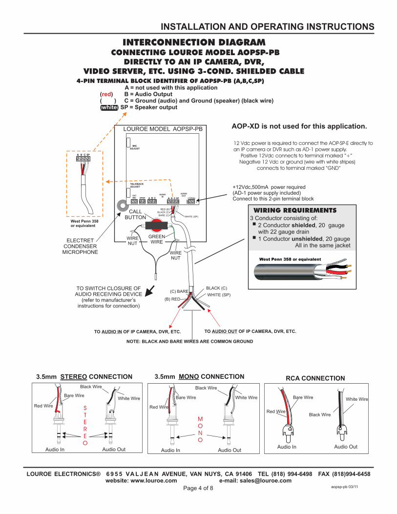
INTERCONNECTION DIAGRAM CONNECTING LOUROE MODEL AOPSP-PB
DIRECTLY TO AN IP CAMERA, DVR, VIDEO SERVER, ETC. USING 3-COND. SHIELDED CABLE
EXT MIC SPKR +12Vdc
AUDIO OUT
AU
DIO
IN
A B C
TALKBACKADJUST
MICADJUST
CA SPB
LOUROE MODEL AOPSP-PB
WHITE (SP)
BLACK (C)(C) BARE
(B) RED
TO AUDIO OUT OF IP CAMERA, DVR, ETC.TO AUDIO IN OF IP CAMERA, DVR, ETC.
NOTE: BLACK AND BARE WIRES ARE COMMON GROUND
BARE (C)
BLACK (C)RED (B)
4-PIN TERMINAL BLOCK IDENTIFIER OF AOPSP-PB (A,B,C,SP)
( ) B = Audio Output ( ) C = Ground (audio) and Ground (speaker) (black wire)( ) SP = Speaker output
A = not used with this applicationredbarewhite
West Penn 358or equivalent
CA SPB
WHITE (SP)
Audio OutAudio Out Audio In
Audio In
Bare Wire
Red Wire
RCA CONNECTION3.5mm MONO CONNECTION 3.5mm STEREO CONNECTION
White Wire
Black Wire
Black Wire
White Wire
Red Wire
Bare Wire
MONO
STEREO
Audio OutAudio In
Red Wire
Black Wire
White WireBare Wire
WIRING REQUIREMENTS 3 Conductor consisting of:
+2 Conductor shielded, 20 gauge with 22 gauge drain
+1 Conductor unshielded, 20 gauge All in the same jacket
CALL BUTTON
ELECTRETCONDENSERMICROPHONE
GREEN WIRE
WIRE NUT
WIRE NUT
TO SWITCH CLOSURE OFAUDIO RECEIVING DEVICE
(refer to manufacturer’sinstructions for connection)
EXT MIC SPKR
AUDIO OUT
AUDIOIN
AOP-XD is not used for this application.
+12Vdc,500mA power required(AD-1 power supply included)Connect to this 2-pin terminal block
12 Vdc power is required to connect the AOP-SP-E directly to an IP camera or DVR such as AD-1 power supply. Positive 12Vdc connects to terminal marked “+” Negative 12 Vdc or ground connects to terminal marked “GND”
(wire with white stripes)
+12Vdc
+GN
D
Page 4 of 8
LOUROE ELECTRONICS® 6 9 5 5 VA L J E A N AVENUE, VAN NUYS, CA 91406 TEL (818) 994-6498 FAX 994-6458website: www.louroe.com e-mail: [email protected]
(818)
INSTALLATION AND OPERATING INSTRUCTIONS
aopsp-pb 03/11
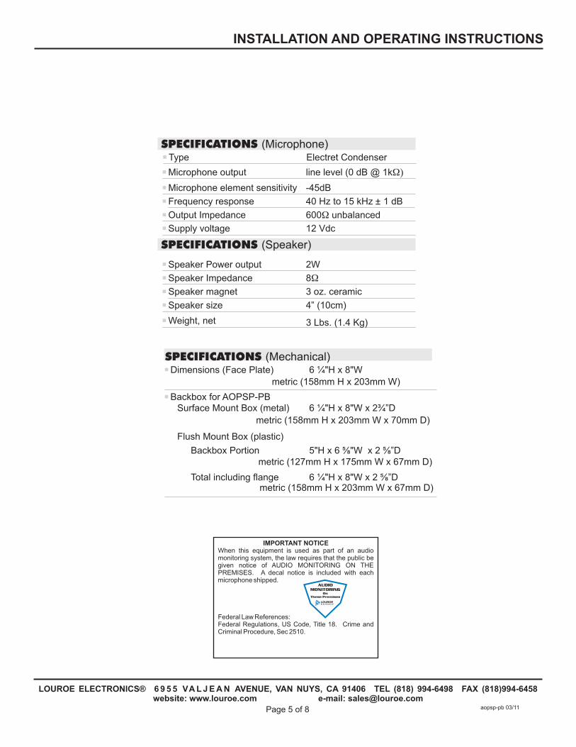
SPECIFICATIONS (Microphone)
Microphone output
Type
line level (0 dB @ 1kΩ)
Electret Condenser
Supply voltage 12 Vdc
SPECIFICATIONS (Speaker)
Speaker Power output
Speaker Impedance
Speaker magnet
Speaker size
Weight, net
2W
8Ω
3 oz. ceramic
4” (10cm)
3 Lbs. (1.4 Kg)
Microphone element sensitivity
Frequency response
Output Impedance
-45dB
40 Hz to 15 kHz 1 dB
600Ω unbalanced
Dimensions (Face Plate) 6 ¼"H x 8"W
Backbox for AOPSP-PB
metric (158mm H x 203mm W)
Surface Mount Box (metal) 6 ¼"H x 8"W x 2¾”D
Flush Mount Box (plastic)
Backbox Portion 5"H x 6 ? "W x 2 ? ”D
Total including flange 6 ¼"H x 8"W x 2 ? ”D metric (158mm H x 203mm W x 67mm D)
metric (127mm H x 175mm W x 67mm D)
metric (158mm H x 203mm W x 70mm D)
Page 5 of 8
LOUROE ELECTRONICS® 6 9 5 5 VA L J E A N AVENUE, VAN NUYS, CA 91406 TEL (818) 994-6498 FAX 994-6458website: www.louroe.com e-mail: [email protected]
(818)
INSTALLATION AND OPERATING INSTRUCTIONS
SPECIFICATIONS (Mechanical)
aopsp-pb 03/11
IMPORTANT NOTICEWhen this equipment is used as part of an audio monitoring system, the law requires that the public be given notice of AUDIO MONITORING ON THE PREMISES. A decal notice is included with each microphone shipped.
Federal Law References:Federal Regulations, US Code, Title 18. Crime and Criminal Procedure, Sec 2510.
AUDIO MONITORING
On These Premises
®

NOTES
Page 6 of 8
LOUROE ELECTRONICS® 6 9 5 5 VA L J E A N AVENUE, VAN NUYS, CA 91406 TEL (818) 994-6498 FAX 994-6458website: www.louroe.com e-mail: [email protected]
(818)
INSTALLATION AND OPERATING INSTRUCTIONS
aopsp-pb 03/11
WARRANTYLOUROE ELECTRONICS® warrants that at the time of shipment products manufactured by LOUROE ELECTRONICS® to be free of defects in material and workmanship. Should a defect appear within one year (12 months) from date of shipment, LOUROE ELECTRONICS® will, at its sole discretion, repair or replace the defective equipment. This equipment shall not be accepted for repair or return without prior notification by LOUROE ELECTRONICS®.
This warranty does not extend to any Louroe product that has been subjected to improper or incorrect installation, misuse, accident, or in violation of installation instructions provided by LOUROE ELECTRONICS®.
Returned shipments to LOUROE ELECTRONICS® shall be at customer’s expense. LOUROE ELECTRONICS® will return the equipment prepaid via best way.
NOTES
INSTALLATION AND OPERATING INSTRUCTIONS
Page 7 of 8
LOUROE ELECTRONICS® 6 9 5 5 VA L J E A N AVENUE, VAN NUYS, CA 91406 TEL (818) 994-6498 FAX 994-6458website: www.louroe.com e-mail: [email protected]
(818)
aopsp-pb 03/11
MANUFACTUREDIN THE
Page 8 of 8
LOUROE ELECTRONICS® 6 9 5 5 VA L J E A N AVENUE, VAN NUYS, CA 91406 TEL (818) 994-6498 FAX 994-6458website: www.louroe.com e-mail: [email protected]
(818)
aopsp-pb 03/11