Embed Size (px)
Citation preview
INSTALLATION
AND OPERATING
MANUAL
Opus 01, 02, 03, 04 Series Showers
INSTALLERS PLEASE NOTE, THESE INSTRUCTIONS ARE TO BE LEFT
WITH THE CUSTOMER
Technical Support: 01422 410769
2
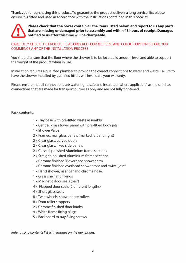
Thank you for purchasing this product. To guarantee the product delivers a long service life, please ensure it is fi tted and used in accordance with the instructions contained in this booklet.
Please check that the boxes contain all the items listed below, and report to us any parts
that are missing or damaged prior to assembly and within 48 hours of receipt. Damages
notifi ed to us after this time will be chargeable.
CAREFULLY CHECK THE PRODUCT IS AS ORDERED: CORRECT SIZE AND COLOUR OPTION BEFORE YOU COMMENCE ANY OF THE INSTALLATION PROCESS
You should ensure that the fl oor where the shower is to be located is smooth, level and able to support the weight of the product when in use.
Installation requires a qualifi ed plumber to provide the correct connections to water and waste Failure to have the shower installed by qualifi ed fi tters will invalidate your warranty.
Please ensure that all connections are water tight, safe and insulated (where applicable) as the unit has connections that are made for transport purposes only and are not fully tightened.
Pack contents:
1 x Tray base with pre-fi tted waste assembly1 x Central, glass tower panel with pre-fi tt ed body jets1 x Shower Valve2 x Framed, rear glass panels (marked left and right)2 x Clear glass, curved doors2 x Clear glass, fi xed side panels2 x Curved, polished Aluminium frame sections2 x Straight, polished Aluminium frame sections1 x Chrome fi nished ‘J’ overhead shower arm1 x Chrome fi nished overhead shower rose and swivel joint 1 x Hand shower, riser bar and chrome hose.1 x Glass shelf and fi xings1 x Magnetic door seals (pair)4 x Flapped door seals (2 different lengths)4 x Short glass seals8 x Twin wheels, shower door rollers.8 x Door roller stoppers2 x Chrome fi nished door knobs4 x White frame fi xing plugs5 x Backboard to tray fi xing screws
Refer also to contents list with images on the next pages.
3
Important Notice
Before you Begin Water Requirements
Assembly
Fitting the Thermostatic ValveLeveling and fi tting the trayJoining Rear Panels and TowerRear Glass Panels to TrayAssembling Front Fixed Glass PanelsFitting Front Fixed GlassInstalling Lower Curved RailUpper Curved Rail installationFixing Panels to Tray
Runner Wheels Handles
Overhead Shower FittingHand shower and Riser installationFixing and Assembly of Glass Shelf
The Shower Valve Door Seals
Water Connections
Sealing the Shower
Final Testing
Completion
Operating Instructions
Safety Precautions
Cleaning and thirds party product use
Additional information and help
Thermostatic Cartridge
Product Contents List with Images
Contents
4
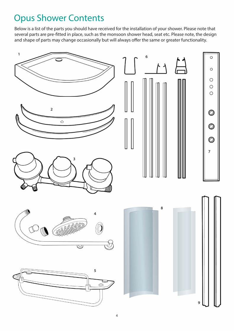
Below is a list of the parts you should have received for the installation of your shower. Please note that several parts are pre-fi tted in place, such as the monsoon shower head, seat etc. Please note, the design and shape of parts may change occasionally but will always off er the same or greater functionality.
Opus Shower Contents
1
2
3
4
5
6
7
8
9
5
1. Tray/Base with Waste assembly and fl exible waste pipepre-fi tted.
2. Two Curved polished Aluminium frame sections.
3. Thermostatic shower valve and 2 braided hoses.
4. Chrome monsoon arm, Monsoon head, swivel joint andtwo nuts for fi xing.
5. Glass shelf and fi ttings.
6. Four short U Seals, Two longer and two shorter Flappedseals and a pair of Magnetic door seals.
7. Tower with and Body Jets pre-fi tted.
8. Two Curved clear glass doors. Two fl at clear glass sidepieces.
9. Frame Uprights. Two polished straight metal sections.
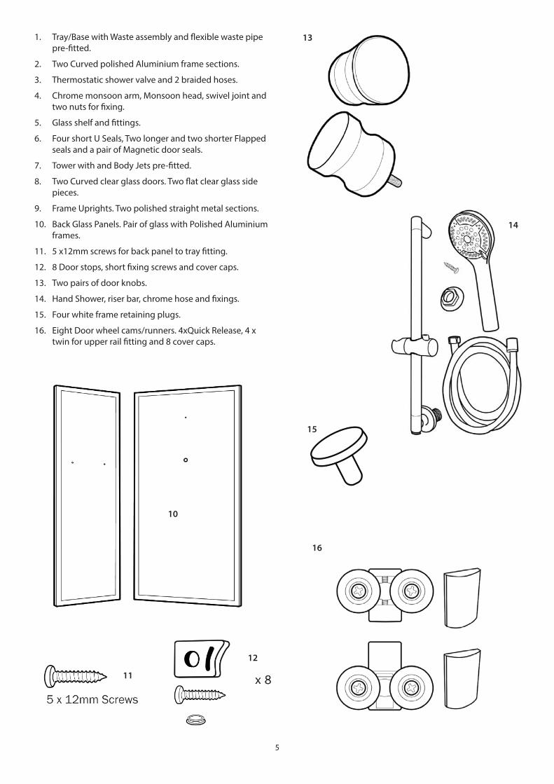
10. Back Glass Panels. Pair of glass with Polished Aluminiumframes.
11. 5 x12mm screws for back panel to tray fi tting.
12. 8 Door stops, short fi xing screws and cover caps.
13. Two pairs of door knobs.
14. Hand Shower, riser bar, chrome hose and fi xings.
15. Four white frame retaining plugs.
16. Eight Door wheel cams/runners. 4xQuick Release, 4 xtwin for upper rail fi tting and 8 cover caps.
10
11
12
13
14
15
16
6
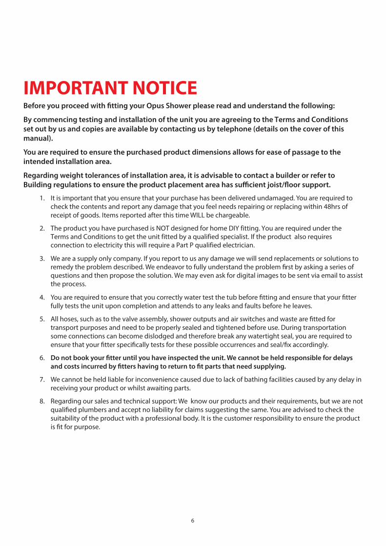
IMPORTANT NOTICEBefore you proceed with fi tting your Opus Shower please read and understand the following:
By commencing testing and installation of the unit you are agreeing to the Terms and Conditions
set out by us and copies are available by contacting us by telephone (details on the cover of this
manual).
You are required to ensure the purchased product dimensions allows for ease of passage to the
intended installation area.
Regarding weight tolerances of installation area, it is advisable to contact a builder or refer to
Building regulations to ensure the product placement area has suffi cient joist/fl oor support.
1. It is important that you ensure that your purchase has been delivered undamaged. You are required tocheck the contents and report any damage that you feel needs repairing or replacing within 48hrs ofreceipt of goods. Items reported after this time WILL be chargeable.
2. The product you have purchased is NOT designed for home DIY fi tting. You are required under the Terms and Conditions to get the unit fi tted by a qualifi ed specialist. If the product also requires connection to electricity this will require a Part P qualifi ed electrician.
3. We are a supply only company. If you report to us any damage we will send replacements or solutions to remedy the problem described. We endeavor to fully understand the problem fi rst by asking a series of questions and then propose the solution. We may even ask for digital images to be sent via email to assist the process.
4. You are required to ensure that you correctly water test the tub before fi tting and ensure that your fi tterfully tests the unit upon completion and attends to any leaks and faults before he leaves.
5. All hoses, such as to the valve assembly, shower outputs and air switches and waste are fi tted fortransport purposes and need to be properly sealed and tightened before use. During transportationsome connections can become dislodged and therefore break any watertight seal, you are required toensure that your fi tter specifi cally tests for these possible occurrences and seal/fi x accordingly.
6. Do not book your fi tter until you have inspected the unit. We cannot be held responsible for delays
and costs incurred by fi tters having to return to fi t parts that need supplying.
7. We cannot be held liable for inconvenience caused due to lack of bathing facilities caused by any delay inreceiving your product or whilst awaiting parts.
8. Regarding our sales and technical support: We know our products and their requirements, but we are notqualifi ed plumbers and accept no liability for claims suggesting the same. You are advised to check thesuitability of the product with a professional body. It is the customer responsibility to ensure the productis fi t for purpose.
7
Before you begin
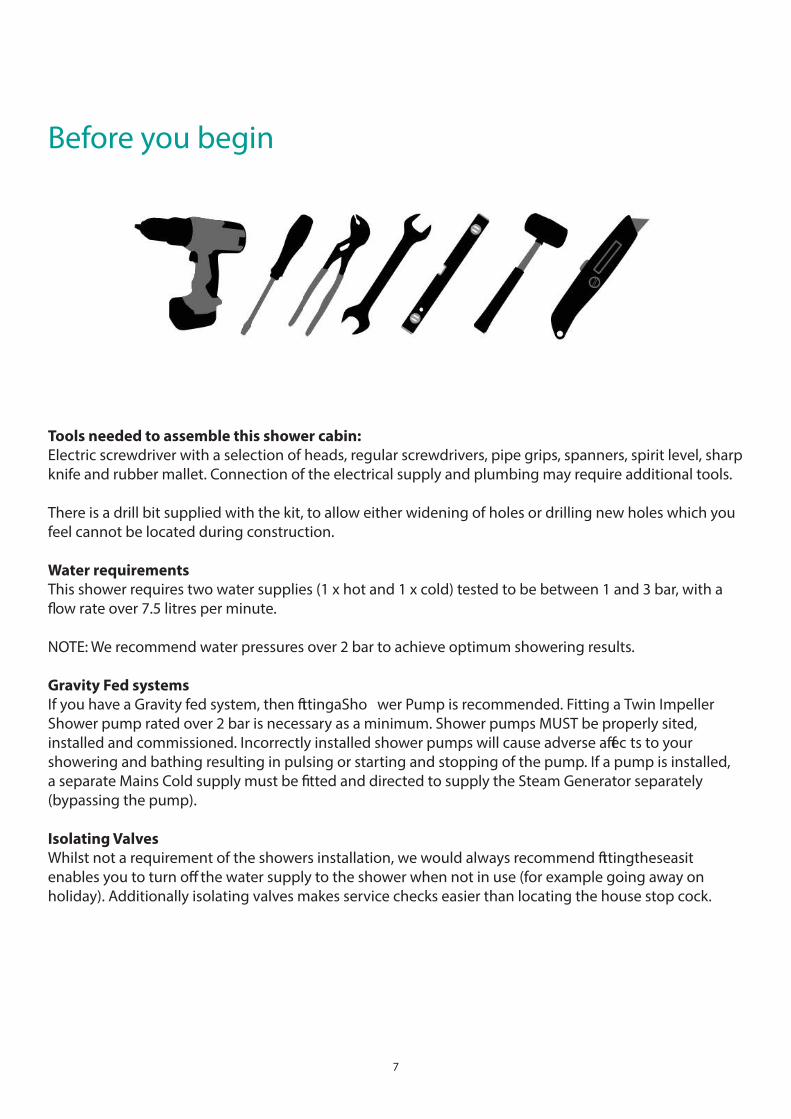
Tools needed to assemble this shower cabin:
Electric screwdriver with a selection of heads, regular screwdrivers, pipe grips, spanners, spirit level, sharp knife and rubber mallet. Connection of the electrical supply and plumbing may require additional tools.
There is a drill bit supplied with the kit, to allow either widening of holes or drilling new holes which you feel cannot be located during construction.
Water requirements
This shower requires two water supplies (1 x hot and 1 x cold) tested to be between 1 and 3 bar, with a fl ow rate over 7.5 litres per minute.
NOTE: We recommend water pressures over 2 bar to achieve optimum showering results.
Gravity Fed systems
If you have a Gravity fed system, then fi tting a Sho wer Pump is recommended. Fitting a Twin Impeller Shower pump rated over 2 bar is necessary as a minimum. Shower pumps MUST be properly sited, installed and commissioned. Incorrectly installed shower pumps will cause adverse aff ec ts to your showering and bathing resulting in pulsing or starting and stopping of the pump. If a pump is installed, a separate Mains Cold supply must be fi tted and directed to supply the Steam Generator separately (bypassing the pump).
Isolating Valves
Whilst not a requirement of the showers installation, we would always recommend fi tting these as it enables you to turn off the water supply to the shower when not in use (for example going away on holiday). Additionally isolating valves makes service checks easier than locating the house stop cock.
8
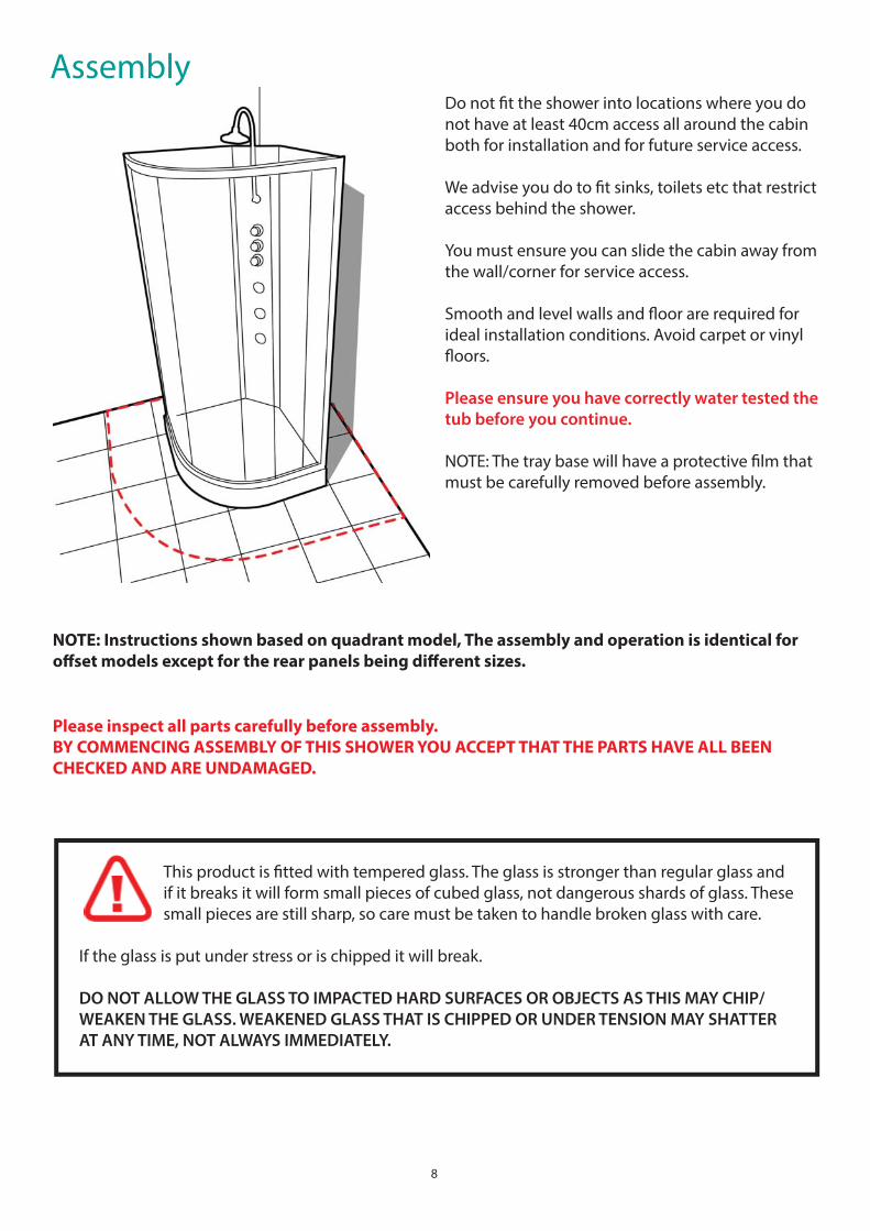
AssemblyDo not fi t the shower into locations where you do not have at least 40cm access all around the cabin both for installation and for future service access.
We advise you do to fi t sinks, toilets etc that restrict access behind the shower.
You must ensure you can slide the cabin away from the wall/corner for service access.
Smooth and level walls and fl oor are required for ideal installation conditions. Avoid carpet or vinyl fl oors.
Please ensure you have correctly water tested the
tub before you continue.
NOTE: The tray base will have a protective fi lm that must be carefully removed before assembly.
NOTE: Instructions shown based on quadrant model, The assembly and operation is identical for
off set models except for the rear panels being diff erent sizes.
Please inspect all parts carefully before assembly.
BY COMMENCING ASSEMBLY OF THIS SHOWER YOU ACCEPT THAT THE PARTS HAVE ALL BEEN
CHECKED AND ARE UNDAMAGED.
This product is fi tted with tempered glass. The glass is stronger than regular glass and if it breaks it will form small pieces of cubed glass, not dangerous shards of glass. These small pieces are still sharp, so care must be taken to handle broken glass with care.
If the glass is put under stress or is chipped it will break.
DO NOT ALLOW THE GLASS TO IMPACTED HARD SURFACES OR OBJECTS AS THIS MAY CHIP/
WEAKEN THE GLASS. WEAKENED GLASS THAT IS CHIPPED OR UNDER TENSION MAY SHATTER
AT ANY TIME, NOT ALWAYS IMMEDIATELY.
9
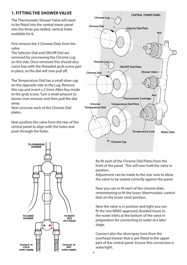
1. FITTING THE SHOWER VALVE
The Thermostatic Shower Valve will need to be fi tted into the central tower panel into the three pre-drilled, vertical holes available for it.
First remove the 3 Chrome Dials from the valve.The Selector Dial and ON/Off Dial are removed by unscrewing the Chrome Lug on the side. Once removed this should also come free with the threaded grub screw part in place, so the dial will now pull off .
The Temperature Dial has a small silver cap on the opposite side to the Lug. Remove this cap and insert a 2.5mm Allen Key inside to the grub screw. Turn a small amount to loosen (not remove) and then pull the dial away.Next unscrew each of the Chrome Dial plates.
Now position the valve from the rear of the central panel to align with the holes and push through the holes.
Re-fi t each of the Chrome Dial Plates from the front of the panel. This will now hold the valve in position.Adjustment can be made to the rear nuts to allow the valve to be seated correctly against the panel.
Now you can re-fi t each of the chrome dials, remembering to fi t the lower (thermostatic control dial) on the lower most position.
Now the valve is in position and tight you can fi t the two WRAS approved, Braided hoses to the water inlets at the bottom of the valve in preparation for connecting to water at a later stage.
Connect also the silver/grey hose from the overhead shower that is pre-fi tted to the upper part of the central panel. Ensure this connection is watertight.
10
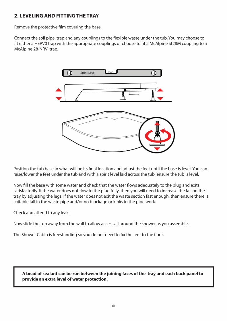
2. LEVELING AND FITTING THE TRAY
Remove the protective fi lm covering the base.
Connect the soil pipe, trap and any couplings to the fl exible waste under the tub. You may choose to fi t either a HEPV0 trap with the appropriate couplings or choose to fi t a McAlpine St28M coupling to a McAlpine 28-NRV trap.
Position the tub base in what will be its fi nal location and adjust the feet until the base is level. You can raise/lower the feet under the tub and with a spirit level laid across the tub, ensure the tub is level.
Now fi ll the base with some water and check that the water fl ows adequately to the plug and exits satisfactorily. If the water does not fl ow to the plug fully, then you will need to increase the fall on the tray by adjusting the legs. If the water does not exit the waste section fast enough, then ensure there is suitable fall in the waste pipe and/or no blockage or kinks in the pipe work.
Check and attend to any leaks.
Now slide the tub away from the wall to allow access all around the shower as you assemble.
The Shower Cabin is freestanding so you do not need to fi x the feet to the fl oor.
A bead of sealant can be run between the joining faces of the tray and each back panel to
provide an extra level of water protection.
11
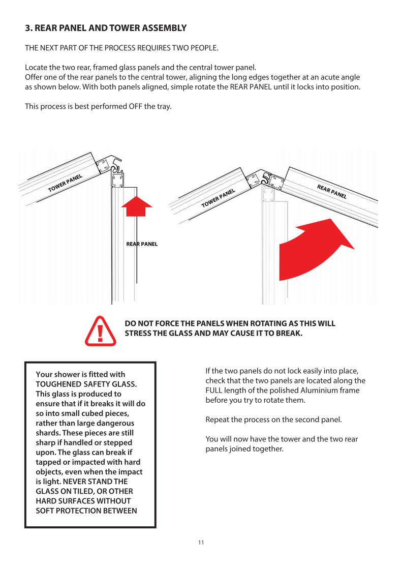
3. REAR PANEL AND TOWER ASSEMBLY
THE NEXT PART OF THE PROCESS REQUIRES TWO PEOPLE.
Locate the two rear, framed glass panels and the central tower panel.Off er one of the rear panels to the central tower, aligning the long edges together at an acute angle as shown below. With both panels aligned, simple rotate the REAR PANEL until it locks into position.
This process is best performed OFF the tray.
DO NOT FORCE THE PANELS WHEN ROTATING AS THIS WILL
STRESS THE GLASS AND MAY CAUSE IT TO BREAK.
Your shower is fi tted with TOUGHENED SAFETY GLASS.
This glass is produced to
ensure that if it breaks it will do
so into small cubed pieces,
rather than large dangerous
shards. These pieces are still
sharp if handled or stepped
upon. The glass can break if
tapped or impacted with hard
objects, even when the impact
is light. NEVER STAND THE
GLASS ON TILED, OR OTHER
HARD SURFACES WITHOUT
SOFT PROTECTION BETWEEN
If the two panels do not lock easily into place, check that the two panels are located along the FULL length of the polished Aluminium frame before you try to rotate them.
Repeat the process on the second panel.
You will now have the tower and the two rear panels joined together.
12
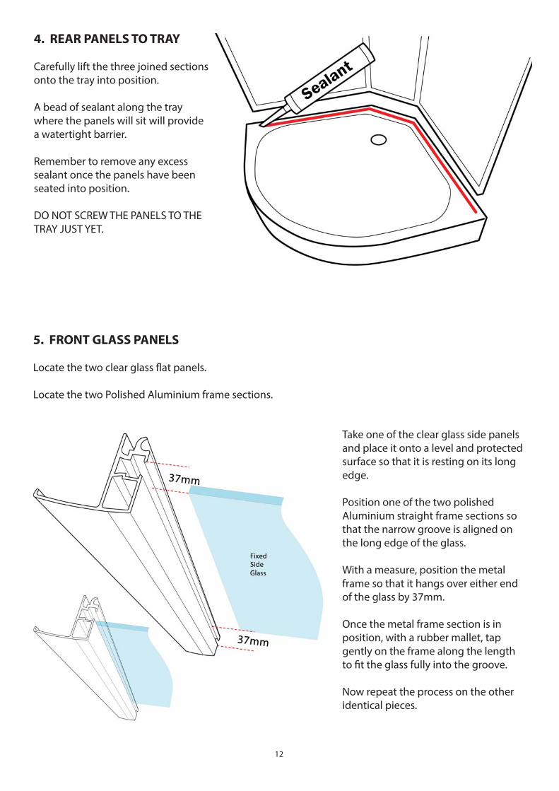
4. REAR PANELS TO TRAY
Carefully lift the three joined sections onto the tray into position.
A bead of sealant along the tray where the panels will sit will provide a watertight barrier.
Remember to remove any excess sealant once the panels have been seated into position.
DO NOT SCREW THE PANELS TO THE TRAY JUST YET.
5. FRONT GLASS PANELS
Locate the two clear glass fl at panels.
Locate the two Polished Aluminium frame sections.
Take one of the clear glass side panels and place it onto a level and protected surface so that it is resting on its long edge.
Position one of the two polished Aluminium straight frame sections so that the narrow groove is aligned on the long edge of the glass.
With a measure, position the metal frame so that it hangs over either end of the glass by 37mm.
Once the metal frame section is in position, with a rubber mallet, tap gently on the frame along the length to fi t the glass fully into the groove.
Now repeat the process on the other identical pieces.
13
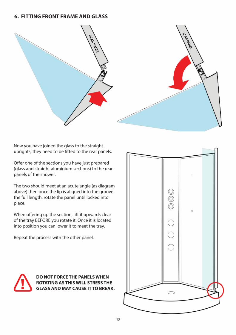
6. FITTING FRONT FRAME AND GLASS
Now you have joined the glass to the straight uprights, they need to be fi tted to the rear panels.
Off er one of the sections you have just prepared (glass and straight aluminium sections) to the rear panels of the shower.
The two should meet at an acute angle (as diagram above) then once the lip is aligned into the groove the full length, rotate the panel until locked into place.
When off ering up the section, lift it upwards clear of the tray BEFORE you rotate it. Once it is located into position you can lower it to meet the tray.
Repeat the process with the other panel.
DO NOT FORCE THE PANELS WHEN
ROTATING AS THIS WILL STRESS THE
GLASS AND MAY CAUSE IT TO BREAK.
14
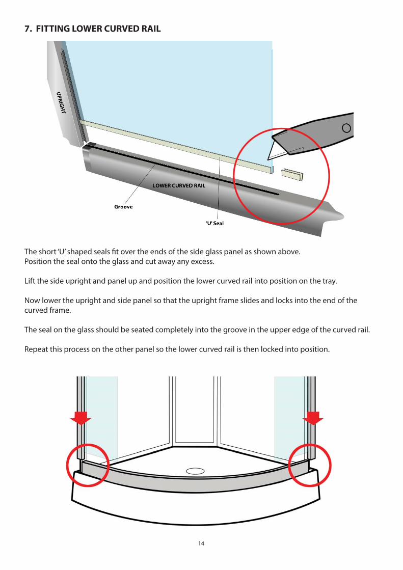
The short ‘U’ shaped seals fi t over the ends of the side glass panel as shown above.Position the seal onto the glass and cut away any excess.
Lift the side upright and panel up and position the lower curved rail into position on the tray.
Now lower the upright and side panel so that the upright frame slides and locks into the end of the curved frame.
The seal on the glass should be seated completely into the groove in the upper edge of the curved rail.
Repeat this process on the other panel so the lower curved rail is then locked into position.
7. FITTING LOWER CURVED RAIL
15
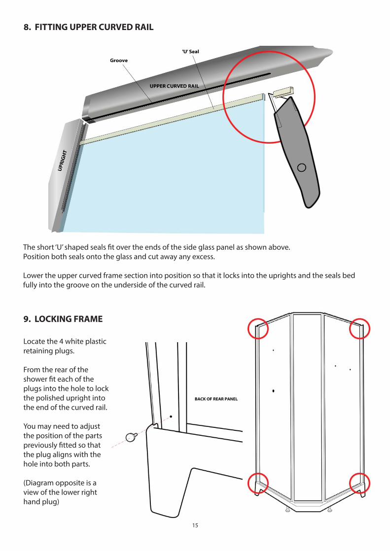
8. FITTING UPPER CURVED RAIL
The short ‘U’ shaped seals fi t over the ends of the side glass panel as shown above.Position both seals onto the glass and cut away any excess.
Lower the upper curved frame section into position so that it locks into the uprights and the seals bed fully into the groove on the underside of the curved rail.
9. LOCKING FRAME
Locate the 4 white plastic retaining plugs.
From the rear of the shower fi t each of the plugs into the hole to lock the polished upright into the end of the curved rail.
You may need to adjust the position of the parts previously fi tted so that the plug aligns with the hole into both parts.
(Diagram opposite is a view of the lower right hand plug)
16
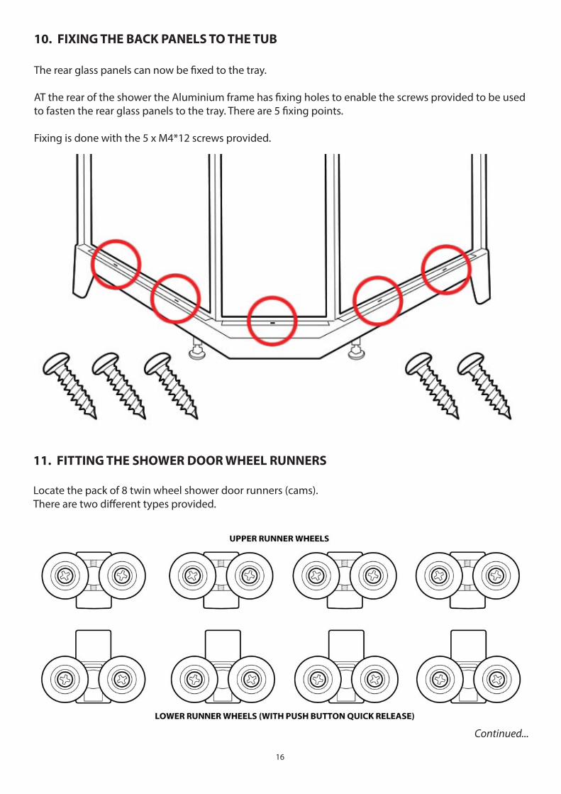
10. FIXING THE BACK PANELS TO THE TUB
The rear glass panels can now be fi xed to the tray.
AT the rear of the shower the Aluminium frame has fi xing holes to enable the screws provided to be used to fasten the rear glass panels to the tray. There are 5 fi xing points.
Fixing is done with the 5 x M4*12 screws provided.
11. FITTING THE SHOWER DOOR WHEEL RUNNERS
Locate the pack of 8 twin wheel shower door runners (cams).There are two diff erent types provided.
Continued...
17
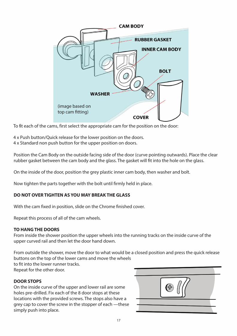
(image based ontop cam fi tting)
To fi t each of the cams, fi rst select the appropriate cam for the position on the door:
4 x Push button/Quick release for the lower position on the doors. 4 x Standard non push button for the upper position on doors.
Position the Cam Body on the outside facing side of the door (curve pointing outwards). Place the clear rubber gasket between the cam body and the glass. The gasket will fi t into the hole on the glass.
On the inside of the door, position the grey plastic inner cam body, then washer and bolt.
Now tighten the parts together with the bolt until fi rmly held in place.
DO NOT OVER TIGHTEN AS YOU MAY BREAK THE GLASS
With the cam fi xed in position, slide on the Chrome fi nished cover.
Repeat this process of all of the cam wheels.
TO HANG THE DOORS
From inside the shower position the upper wheels into the running tracks on the inside curve of the upper curved rail and then let the door hand down.
From outside the shower, move the door to what would be a closed position and press the quick release buttons on the top of the lower cams and move the wheels to fi t into the lower runner tracks.Repeat for the other door.
DOOR STOPS
On the inside curve of the upper and lower rail are some holes pre-drilled. Fix each of the 8 door stops at these locations with the provided screws. The stops also have a grey cap to cover the screw in the stopper of each —these simply push into place.
18
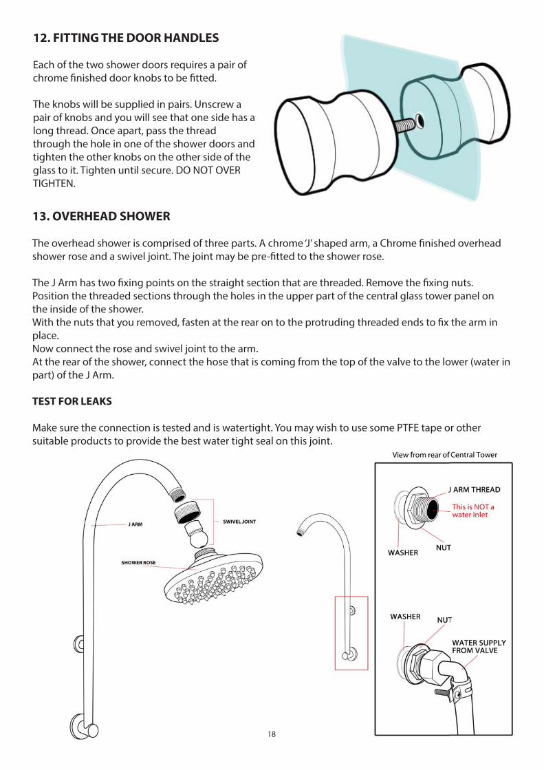
12. FITTING THE DOOR HANDLES
Each of the two shower doors requires a pair of chrome fi nished door knobs to be fi tted.
The knobs will be supplied in pairs. Unscrew a pair of knobs and you will see that one side has a long thread. Once apart, pass the thread through the hole in one of the shower doors and tighten the other knobs on the other side of the glass to it. Tighten until secure. DO NOT OVER TIGHTEN.
13. OVERHEAD SHOWER
The overhead shower is comprised of three parts. A chrome ‘J’ shaped arm, a Chrome fi nished overhead shower rose and a swivel joint. The joint may be pre-fi tted to the shower rose.
The J Arm has two fi xing points on the straight section that are threaded. Remove the fi xing nuts.Position the threaded sections through the holes in the upper part of the central glass tower panel on the inside of the shower.With the nuts that you removed, fasten at the rear on to the protruding threaded ends to fi x the arm in place.Now connect the rose and swivel joint to the arm.At the rear of the shower, connect the hose that is coming from the top of the valve to the lower (water in part) of the J Arm.
TEST FOR LEAKS
Make sure the connection is tested and is watertight. You may wish to use some PTFE tape or other suitable products to provide the best water tight seal on this joint.
19
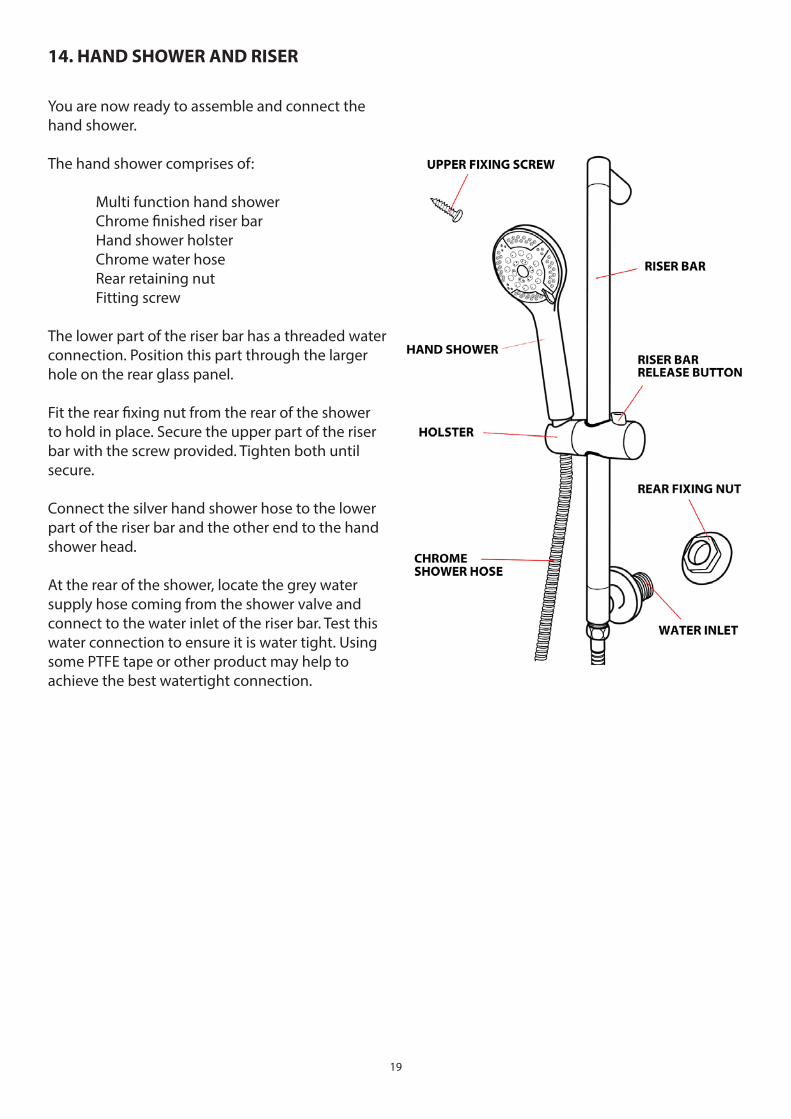
14. HAND SHOWER AND RISER
You are now ready to assemble and connect the hand shower.
The hand shower comprises of:
Multi function hand shower Chrome fi nished riser bar
Hand shower holsterChrome water hoseRear retaining nut
Fitting screw
The lower part of the riser bar has a threaded water connection. Position this part through the larger hole on the rear glass panel.
Fit the rear fi xing nut from the rear of the shower to hold in place. Secure the upper part of the riser bar with the screw provided. Tighten both until secure.
Connect the silver hand shower hose to the lower part of the riser bar and the other end to the hand shower head.
At the rear of the shower, locate the grey water supply hose coming from the shower valve and connect to the water inlet of the riser bar. Test this water connection to ensure it is water tight. Using some PTFE tape or other product may help to achieve the best watertight connection.
20
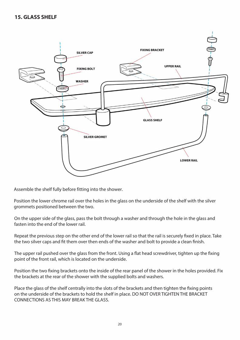
15. GLASS SHELF
Assemble the shelf fully before fi tting into the shower.
Position the lower chrome rail over the holes in the glass on the underside of the shelf with the silver grommets positioned between the two.
On the upper side of the glass, pass the bolt through a washer and through the hole in the glass and fasten into the end of the lower rail.
Repeat the previous step on the other end of the lower rail so that the rail is securely fi xed in place. Take the two silver caps and fi t them over then ends of the washer and bolt to provide a clean fi nish.
The upper rail pushed over the glass from the front. Using a fl at head screwdriver, tighten up the fi xing point of the front rail, which is located on the underside.
Position the two fi xing brackets onto the inside of the rear panel of the shower in the holes provided. Fix the brackets at the rear of the shower with the supplied bolts and washers.
Place the glass of the shelf centrally into the slots of the brackets and then tighten the fi xing points on the underside of the brackets to hold the shelf in place. DO NOT OVER TIGHTEN THE BRACKET CONNECTIONS AS THIS MAY BREAK THE GLASS.
21
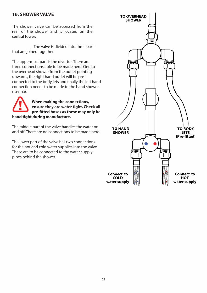
16. SHOWER VALVE
The shower valve can be accessed from the rear of the shower and is located on the central tower.
The valve is divided into three parts that are joined together.
The uppermost part is the divertor. There are three connections able to be made here. One to the overhead shower from the outlet pointing upwards, the right hand outlet will be pre-connected to the body jets and fi nally the left hand connection needs to be made to the hand shower riser bar.
When making the connections,
ensure they are water tight. Check all
pre-fi tted hoses as these may only be
hand tight during manufacture.
The middle part of the valve handles the water on and off . There are no connections to be made here.
The lower part of the valve has two connections for the hot and cold water supplies into the valve. These are to be connected to the water supply pipes behind the shower.
22
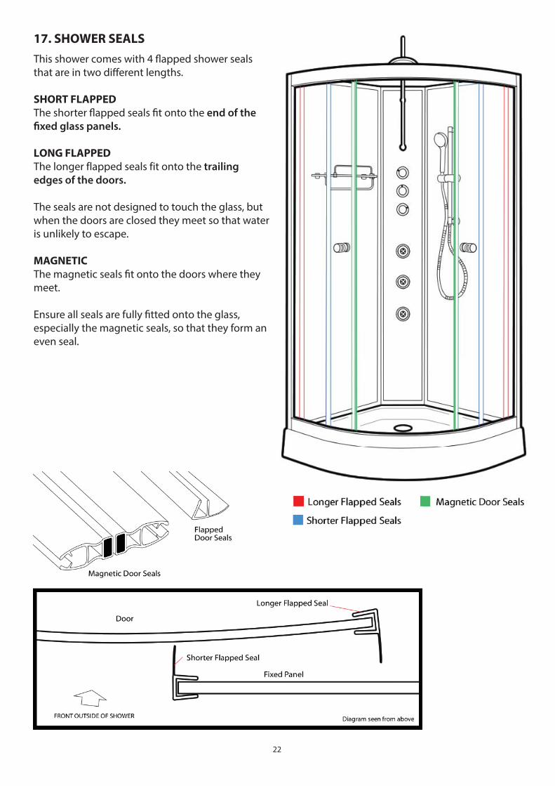
This shower comes with 4 fl apped shower seals that are in two diff erent lengths.
SHORT FLAPPED
The shorter fl apped seals fi t onto the end of the
fi xed glass panels.
LONG FLAPPED
The longer fl apped seals fi t onto the trailing
edges of the doors.
The seals are not designed to touch the glass, but when the doors are closed they meet so that water is unlikely to escape.
MAGNETIC
The magnetic seals fi t onto the doors where they meet.
Ensure all seals are fully fi tted onto the glass, especially the magnetic seals, so that they form an even seal.
17. SHOWER SEALS
23
Water ConnectionsThis product requires a hot and cold water supply. The Hot and Cold water should ideally be fi nished about 1 meter above the fl oor centrally in the corner and fi nished with 15mm compression fi ttings. The shower has two braided fl exible hoses that connect to the water supply pipes.
WATER PRESSURE: 1-3 bar (ideally above 2 for optimum results)WATER FLOW: above 7.5 litres per minute
Fitting Isolating valves is recommended as this makes service access easier than locating the house Stop Cock. Additionally Isolating valve enable you to disconnect water to the shower if you are away from home for long periods of time.
Combination boiler installation and PEV’s
The Opus Shower cabin does not normally require a Pressure Equalising Valve (PEV) as it uses the latest generation of shower valve fi tted with Thermostatic Cartridge, which enables it to handle un balanced water pressures itself, to provide accurate temperature control.The Opus can be connected to Combi Boiler system that provide suitable water pressure and water fl ow rates.
Gravity Fed and Shower Pumps
Where the water is supplied by a hot water cylinder (gravity fed type systems) a shower pump should be installed. Ideally a shower pump rated over 2 bar supplying just the shower is recommended, or alternatively a pump of higher specifi cation can be fi tted to supply multiple showers within the property.
When choosing a pump, a twin impeller pump is recommended as this will ensure both the hot and cold water is of the same pressure.
Always refer to the manufacturers instructions regarding shower pump installations and choose the correct type for your particular situation (negative head/positive head etc). All pipe work between the storage tank, cylinder and to the pump should be 22mm and the shower positioned at least 250mm below the header tank. Please note that locating the pump further from the shower and cylinder may reduce the eff ectiveness of the pump and will certainly reduce the output pressure of water.
Ensure the pump is correctly installed and commissioned. Failure to fi t the pump in accordance with the manufactures instructions may result in inadequate water supplies and lead to pump pulsing etc.
Maximum pressure: The shower requires water pressure up to but not exceeding 3 bar.
Exceeding this maximum rating may damage the product and will invalidate your Guarantee.
CHECK ALL WATER CONNECTIONS ARE WATERTIGHT. PREFITTED CONNECTIONS MAY
ONLY BE MADE HAND TIGHT AT MANUFACTURE AND/OR MAY WORK LOOSE IN TRANSIT
24
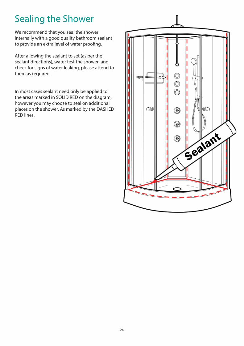
Sealing the ShowerWe recommend that you seal the shower internally with a good quality bathroom sealant to provide an extra level of water proofi ng.
After allowing the sealant to set (as per the sealant directions), water test the shower and check for signs of water leaking, please attend to them as required.
In most cases sealant need only be applied to the areas marked in SOLID RED on the diagram, however you may choose to seal on additional places on the shower. As marked by the DASHED RED lines.
25
Final TestingCheck and test that each outlet function (hand shower, body jets and monsoon) work as expected by rotating the DIVERTOR DIAL (top chrome dial).
Check the ON/OFF dial enables the water to be fully on or off in the position indicated on the valve markings.
Check the Temperature can be increased and decreased by turning the lower chrome shower valve dial. Test that the button can be pressed at 38 degrees to turn the dial to the hottest settings.
Check the water runs to the waste/plug effi ciently. A small amount remaining in the tray is normal.
FAULT FINDING
Water does not exit tray fast enough.
The tray must be leveled and a suitable ‘fall’ on the tray that enable the water to run to the plug. Additionally, the waste hose (under the tray) should have suitable fall to allow water to exit quickly.
Water pressure / fl ow is low on some or all shower options.
Check all the hoses are not trapped or kinked and thus restricting fl ow. Check also that any washers are not out of position and restricting fl ow. Ensure you have OVER 7.5 litres per minute fl ow and over 2 bar water pressure.
Water is ‘pulsing’ .
If a pump has been used to supply water under pressure and the back jets, or hand shower cause the pump to start and stop (PULSING WATER), remove the NON RETURN VALVES. Remove the Braided hoses at the rear of the shower. Look inside the valve where the hoses connected and you will see a silver coloured ‘C’ clip. Remove this and this will enable the NRV to be removed (white plastic item). Refi t the hoses and re-test. Pulsing may also be noted where a pump has not been fully commissioned and there is air in the system.
Doors do not meet correctly and or bind when opening or closing.
Adjust the door runner cam wheels correctly to enable smooth running and operation.
Water is leaking out of the shower.
Dry the shower fully. Once dry, turn on the shower and operate the functions and look for where the water is leaking from. Apply sealant to the area where the water is leaking from.
The shower temperature is low.
If the water in the rest of the house is at a suitable temperature, then you may need to replace the thermostatic cartridge. Limescale or other dirt can impair the function of the cartridge.
For more help with your shower, please call 01422 410769 and our technical team will be on hand to help.
26
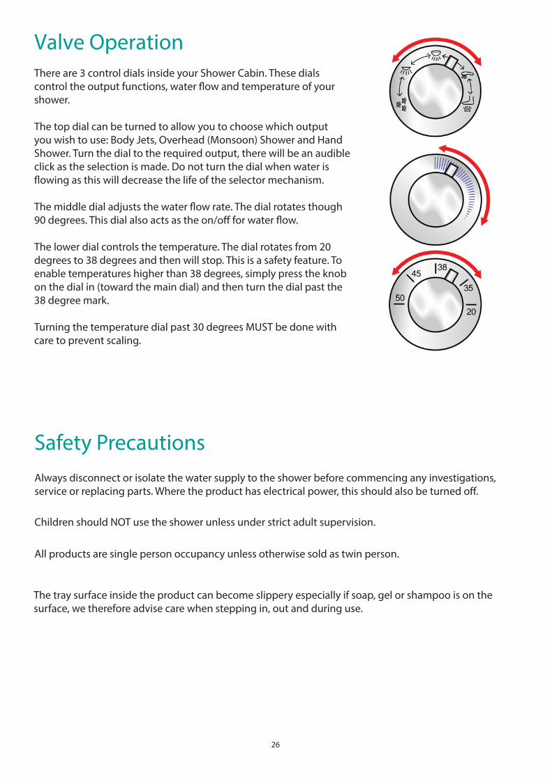
Valve OperationThere are 3 control dials inside your Shower Cabin. These dials control the output functions, water fl ow and temperature of your shower.
The top dial can be turned to allow you to choose which output you wish to use: Body Jets, Overhead (Monsoon) Shower and Hand Shower. Turn the dial to the required output, there will be an audible click as the selection is made. Do not turn the dial when water is fl owing as this will decrease the life of the selector mechanism. The middle dial adjusts the water fl ow rate. The dial rotates though 90 degrees. This dial also acts as the on/off for water fl ow. The lower dial controls the temperature. The dial rotates from 20 degrees to 38 degrees and then will stop. This is a safety feature. To enable temperatures higher than 38 degrees, simply press the knob on the dial in (toward the main dial) and then turn the dial past the 38 degree mark.
Turning the temperature dial past 30 degrees MUST be done with care to prevent scaling.
Safety PrecautionsAlways disconnect or isolate the water supply to the shower before commencing any investigations, service or replacing parts. Where the product has electrical power, this should also be turned off .
Children should NOT use the shower unless under strict adult supervision.
All products are single person occupancy unless otherwise sold as twin person.
The tray surface inside the product can become slippery especially if soap, gel or shampoo is on the surface, we therefore advise care when stepping in, out and during use.
27
Cleaning and third party product useThis shower should be cleaned after every use to remove the build up of dirt and bacteria. We would recommend that after normal showering use, that the cabin doors are left open until the inside is fully dry. This will help prevent the build up of soap scum, dirt and bacteria.
The shower cabin can trap dirt in gaps between joints of panels etc, which may require extra care and attention during cleaning. To minimise dirt build up between panels, the application of a bead of silicone sealant suitable for shower/bathroom use will fi ll the gap leaving a smooth fi nish and both stop dirt build up and off er an extra level of water tightness.
The shower cabin can be cleaned with any suitable cleaning solution that is not abrasive, and is recommended by its manufacturer for use on acrylic, chrome and glass surfaces as appropriate to the materials in the shower. Not all general bathroom cleaners are designed for use on some materials of this product.
DO NOT USE CIF OR OTHER ABRASIVE CLEANING PRODUCTS ON THIS SHOWER.
In hard-water areas, wash down the unit and remove the dirt periodically. Fitting a water fi ltration device is also advisable in areas where the water is likely to lead to a build up of minerals within the pipes and divertor assembly. Hard water WILL reduces the life of the Parts that come into contact with water, such as the Thermostatic Valve. Fitting water softening devices will prevent this.
Additional information and helpFor full guarantee details on this product please call sales on 01422 356863 or technical on 01422 410769
For more details on the installation of this shower, technical support, FAQ please call The Technical Helpline on 01422 410769
If you need a replacement part for your product, please call us on 01422 410769 with the details of your product. Please ensure you have your order number and supplier at hand.
To fi nd parts for your product after the Guarantee has expired,please call:01422 410769
28
Thermostatic CartridgeYour shower is fi tted with a Thermostatic Cartridge. Should you need to remove or replace the cartridge for maintenance or replacement, follow the instructions below.
Q: I am having to turn the dial round as far as it will go to the hottest setting and the water is only just warm.
A: Your Thermostatic Cartridge has showed signs of failure. You will need to replace the Car-tridge.
Q: Why did my Thermostatic Cartridge fail?
A: Hard Water areas will result in calcifi cation, which will build up in the Cartridge. Other rea-sons might be age of the Cartridge or even dirt or debris collecting in the Cartridge from the pipes.
BEFORE STARTING ENSURE THAT THE WATER SUPPLIES ARE DISCONNECTED OR ISOLATED
It is imperative that the water supply to your shower is between 1 and 3 bar as exceeding this may dam-age the Thermostatic Cartridge.
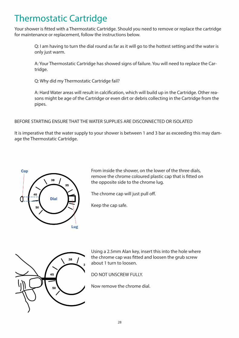
From inside the shower, on the lower of the three dials, remove the chrome coloured plastic cap that is fi tted on the opposite side to the chrome lug.
The chrome cap will just pull off .
Keep the cap safe.
Using a 2.5mm Alan key, insert this into the hole where the chrome cap was fi tted and loosen the grub screw about 1 turn to loosen.
DO NOT UNSCREW FULLY.
Now remove the chrome dial.
29
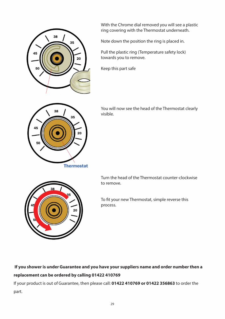
With the Chrome dial removed you will see a plastic ring covering with the Thermostat underneath.
Note down the position the ring is placed in.
Pull the plastic ring (Temperature safety lock) towards you to remove.
Keep this part safe
You will now see the head of the Thermostat clearly visible.
Turn the head of the Thermostat counter-clockwise to remove.
To fi t your new Thermostat, simple reverse this process.
If you shower is under Guarantee and you have your suppliers name and order number then a
replacement can be ordered by calling 01422 410769
If your product is out of Guarantee, then please call: 01422 410769 or 01422 356863 to order the
part.

30
FOR TECHNICAL ASSISTANCE
PLEASE CALL
01422 410769