Embed Size (px)
Citation preview

USO
RES
TRIT
OInstallation and Operating Manual
Version: 4.3
June 18, 2015
UD Series Displays

USO
RES
TRIT
O

USO
RES
TRIT
O
Installation and Operating Manual UD Series Displays Page 3
CONTENTS
A1 REVISION HISTORY
A2 COPYRIGHT
A3 WARRANTY
A4 UNPACKING/SHIPPING/REPACKAGING INFORMATION
A5 SAFETY INSTRUCTIONS
A6 CERTIFICATIONS & COMPLIANCES
FUNCTIONAL DESCRIPTION 15
INTRODUCTION 15
MODELS 17
ACCESSORIES AND OPTIONS 19
EPSW: External AC/DC Power Supply 19 UD-AP: Optional AC Power Inlet, attached 19 UD-BP: Optional AC Power Inlet, integrated 19 UD-PoE: Power over Ethernet 19 UD56-W: Wall, Tripod, and Table Mount Kit 20 UD56S, UD56LS and UD56ES: Integrated LED Seconds Ring for UD56 21 UD300D, UD300LD and UD300ED: Appended Display for UD300 21
INTERFACES 22
LTC (MTD) 22 IRIG 22 RS485 (MTD) 22 GPI 24 RS232/RS422 24 Ethernet 25
STATUS AFTER POWER-ON 26
Displays in LTC, IRIG or serial modes 26 Displays in Ethernet mode 27
FIRMWARE UPDATE 29
CONFIGURATION 31
The UD/SC Configuration Program 31 “Profile“ Tab: Store and Load a Complete Set-Up 33 “System“ Tab: View and Change System Parameters 35 “Source“ Tab: Select the Signal Source 37 “LTC“ Tab: Set-Up of the LTC Reader 39 “Serial“ Tab: Set-Up of the Serial Interface 40 “Ethernet“ Tab: IP Addresses ... 43 “Real-Time“ Tab: Set the Time Zone Parameters 45 “Display“ Tab: Display Mode, Brightness, ... 48 “GPI“ Tab: Programming GPI as Input or Output 52
SPECIAL FEATURES 58
Colour Changing Modes 58 Switching the Display Mode by a Button 59
USO
RES
TRIT
O
Installation and Operating Manual UD Series Displays Page 4
TECHNICAL DATA 61
CONNECTIONS AT THE REAR 61
SPECIFICATIONS 63
AC/DC POWER SUPPLIES 67
UD-EP: External Power Adapter 67 UD-AP: Attached AC Power Inlet 68 UD-BP: Integrated AC Power Inlet 70 PI: Ethernet Power Injector for UD-PoE 71 Notes on PoE Operation 73 Safety Precautions 74
APPLICATIONS 76
CONTROLLING MTD STOP TIMERS BY USE OF GPI COMMANDS 76
MTD SLAVE: LOCAL STOP TIMER AND EXTERNAL DISPLAYS 77
REAL-TIME DISPLAY WITH A GPS16/GPS17 REFERENCE 79
REAL-TIME DISPLAY WITH A RUB GPS 10 MHZ REFERENCE 81
INSTALLATION 84
TERMINAL BLOCK CONNECTIONS 84
LTC/MTD LOOP ADAPTER 85
STRAIN RELIEF FOR CONNECTING CABLES: UTILIZING CABLE TIE HOLDERS 86
UD56-W: WALL, TRIPOD, AND TABLE MOUNT KIT 87
UD300: WALL MOUNTING 89
UD126 + UD178: MOUNTING AND TECHNICAL DATA 90
UD25TT: SPACE SAVING HOUSING 92

USO
RES
TRIT
O
Installation and Operating Manual UD Series Displays Page 5
A1 Revision History
No. Date Subject
0.x Preliminary documents, changes without notice.
1.0 August 27, 2008 First released document.
1.1 September 04, 2008 UD56.
1.2 September 15, 2008 UD56E.
Revised.
1.3 October 23, 2008 Operating mode “MTD Slave”.
1.4 October 28, 2008 GPI features.
1.5 November 13, 2008 Operating mode “MTD Slave” extended.
New: Chapter “Special Features – Colour Changing Modes”.
1.6 March 02, 2009 Wall and table mount kit: UD56-W.
UD300.
2.0 March 20, 2009 Completely revised.
2.1 April 29, 2009 Status after power-on and RS232/RS422 revised.
New: Specification of free-run accuracy.
New: Chapter “Real-Time Display with a GPS16/GPS17 Reference”.
New: Chapter “Real-Time Display with a RUB GPS 10 MHz Reference”.
2.2 June 16, 2009 Revised.
New feature “Set Clock” at the “Real-Time” tab.
New feature “Reset+Continue” at the “GPI” tab.
Housing UD25TT.
3.0 March 25, 2010 Revised.
MTDoE and PoE versions.
3.1 April 16, 2010 Revised.
UD-AP: Attached power supply.
New rear with XLR connectors.
3.2 December 02, 2010 UD300LD and UD300ED.
Installation: Cable tie holders.
3.3 December 21, 2010 UD126L (preliminary).
3.4 April 12, 2011 UD126L/UD126E.
UD56 housing: Depth will change from 45 mm to 56 mm.
UD-BP: Integrated power supply.
New GPI functions.
Special features: Switching the display mode by a button.
3.5 May 13, 2011 New GPI features.
3.6 May 30, 2011 Technical data revised.
GPS connection changed regarding PPS input.
3.7 February 10, 2012 Changes at tab “Ethernet”.
New: Store and load “profiles”.
New serial protocols.
New GPI modes.
Description of a “Loop Adapter” for “L” version displays.
3.8 August 10, 2012 Page layout revised.
3.9 August 01, 2013 Tab “Ethernet”: It is possible to enter an IP address of a “Secondary MTD Master”.
UD56-W: Now fitted with tripod screw thread.
3.A October 23, 2013 UD178L/UD178E.
Table of “Readability/Distance” added to Specifications.
3.B April 02, 2014 Chapter “System Tab: View and Change System Parameters”: added note if password is lost.
4.0 April 24, 2014 New chapter: “PI: Ethernet Power Injector for Option UD-PoE”.
4.1 May 02, 2014 New chapter: “Notes on PoE Operation”.
Chapter revised: “UD56-W: Wall, Tripod, and Table Mont Kit”.
Chapter revised: “Real-Time Tab: Set the Time Zone Parameters”.
4.2 July 31, 2014 Chapter revised: “Models”.
Chapter revised: “Connections at the Rear”.
Chapter revised: “UD56-W: Wall, Tripod, and Table Mont Kit”.
4.3 May 28, 2015 Added “universal” display versions.
Due to constant product development the features of UD Series Displays are subject to
change. The current functional description always refers to the current firmware and the

USO
RES
TRIT
O
Installation and Operating Manual UD Series Displays Page 6
current configuration tool. You can download the latest version of the standard firmware
from
http://www.plurabroadcast.com
Please be sure to use the latest configuration program after having done an update. You can
download the latest version from the address above.

USO
RES
TRIT
O
Installation and Operating Manual UD Series Displays Page 7
A2 Copyright
Copyright © PLURA Europe GmbH 2002. All rights reserved. No part of this publication may
be reproduced, translated into another language, stored in a retrieval system, or transmitted,
in any form or by any means, electronic, mechanical, photocopying, recording, or otherwise
without the prior written consent of PLURA Europe GmbH.
Printed in Germany.
Technical changes are reserved.
All brand and product names mentioned herein are used for identification purposes only, and
are trademarks or registered trademarks of their respective holders.
Information in this publication replaces all previously published information. PLURA Europe
GmbH assumes no responsibility for errors or omissions. Neither is any liability assumed for
damages resulting from the use of the information contained herein.
For further information please contact your local dealer or:
PLURA Europe GmbH
Muehlweg 11
D-73433 Aalen
Phone: +49 - 7361 – 589 46 0
Fax: +49 - 7361 – 589 46 55
E-Mail: [email protected]
Internet: http://www.plurabroadcast.com

USO
RES
TRIT
O
Installation and Operating Manual UD Series Displays Page 8
A3 Warranty
PLURA warrants that their products will be free from defects in materials and workmanship
for a period of two years from the date of shipment. If this product proves defective during
the warranty period, PLURA, at its option, will repair or replace the defective product without
charge, provided this product is returned to PLURA freight prepaid.
In order to obtain service under this warranty, Customer must notify PLURA of the defect
before expiration of the warranty period and make suitable arrangements for the perfor-
mance of service. Customer shall be responsible for packaging and shipping the defective
product to PLURA, please notice the Shipping Information given below.
This warranty shall not apply to any defect, failure or damage caused by abuse, misuse,
improper use, negligence, accident, modification, alteration, or improper or inadequate
maintenance and care.
This warranty is given by PLURA with respect to this product in lieu of any other warranties,
express or implied. PLURA and its vendors disclaim any implied warranties of merchantability
or fitness for a particular purpose. PLURA’s responsibility to repair or replace defective
products is the sole and exclusive remedy provided to the customer for breach of this
warranty. PLURA and its vendors will not be liable for any indirect, special, incidental, or
consequential damages irrespective of whether PLURA or the vendor has advance notice of
the possibility of such damages.
USO
RES
TRIT
O
Installation and Operating Manual UD Series Displays Page 9
A4 Unpacking/Shipping/Repackaging Information
This product has been carefully inspected, tested and calibrated before shipment to ensure
years of stable and trouble-free service.
The shipping carton and pads provide protection for the product during transit. Retain the
shipping cartons in case subsequent shipment becomes necessary.
Carefully unpack the product from its transit material and carefully check the product for
signs of damage. In the event that the product has been damaged during transit, contact the
carrier and your PLURA dealer.
Please confirm that all items listed on the packing list have been received. Check the items
against your original order to ensure that you have received the correct parts. If any item is
missing, please contact your PLURA dealer.
Ensure that all packaging material is removed from the product and its associated
components before installing the unit.
Products returned to PLURA for servicing or repair should have a tag attached showing:
Name and complete address of the owner and the name of the person that can be
contacted.
Unit’s serial number and a description of the service required or failure detected.
Products returned should be shipped prepaid in the original packaging material if possible. If
the original packaging is not available or is unfit for use, supply an adequate packaging
which should meet the following criteria:
Packaging must be able to withstand the product weight.
Product must be held rigid within the packaging.
Allow at least two inches of space between the product and the container.
The corners of the product must be protected.
Seal the carton with shipping tape or an industrial stapler.
If the product is still within the warranty period, the product will be returned by prepaid
shipment after servicing.

USO
RES
TRIT
O
Installation and Operating Manual UD Series Displays Page 10
A5 Safety Instructions
The general safety information in this part is for both operating and service personnel. PLURA
products are only to be used as directed. Specific warnings and cautions will be found
throughout the manual where they apply.
Review the following safety instructions to avoid injury and prevent damage to this product
or any products connected to it.
Read these instructions.
Keep these instructions.
Heed all warnings.
Follow all instructions.
Safety Terms and Symbols
Terms and Symbols in this manual:
WARNING: Warning statements identify conditions or practices that could result
in injury or loss of life.
CAUTION: Caution statements identify conditions or practices that could result
in damage to this product or other property.
Terms and Symbols which may be found on the product:
ATTENTION: Refer to the manual.
Observe precautions for handling electrostatic-sensitive devices.
Signal Ground.
Product Damage Precautions
PREVENT OVERHEATING
To prevent product overheating, position the unit only where sufficient air
circulation can be maintained. Good air circulation is essential to prevent
internal heat build-up, do not block any ventilation openings. Do not expose the
unit to direct sun light or any other strong lights. Keep the unit away from heat
sources.
PROVIDE PROPER ENVIRONMENT

USO
RES
TRIT
O
Installation and Operating Manual UD Series Displays Page 11
Dust, humidity, shocks and strong electromagnetic fields must be avoided. Do
not expose this apparatus to dripping or splashing water. Ensure that no objects
filled with liquid are placed on the apparatus.

USO
RES
TRIT
O
Installation and Operating Manual UD Series Displays Page 12
OBSERVE EMC REGULATIONS
The EMC regulations are observed only under the following condition: use high
quality shielded cables at data inputs and outputs.
SUSPECTED FAILURES
Whenever it is likely that safe operation is impaired, the apparatus must be
made inoperative and secured against unintended operation. The appropriate
service authority must then be informed. Do not operate with suspected failures.
Servicing is required when the apparatus has been damaged in any way, such as
power-supply is damaged, liquid has been spilled or objects have fallen into the
apparatus, the apparatus has been exposed to rain or moisture, does not
operate normally, or has been dropped.
PREVENTIVE MAINTENANCE: CLEANING
Qualified Service Personnel Only: The apparatus should be cleaned often
enough to prevent dust or dirt from accumulating. Dust accumulating in the
apparatus acts as an insulating blanket, preventing proper cooling, and possibly
causing overheating and component breakdown. Under high humidity
conditions, accumulated dust can also provide an electrical conduction path.
Remove accumulated dust with a soft cloth or small paint brush. Remove
hardened dirt with a soft cloth, dampened in a mild detergent and water
solution. Do not use polish or abrasive cleaners or any other chemical cleaning
agents.
PREVENTIVE MAINTENANCE: VISUAL INSPECTION
Qualified Service Personnel Only: Visually inspect the apparatus for signs of
damage, scorched components, and loose or disconnected pin connectors. If
you discover heat damaged parts, try to determine the cause of the overheating
before replacing the damaged parts; otherwise, the damage may repeat.
ATTENTION:
Observe precautions for handling electrostatic-sensitive devices. See “Electro
Static Discharge (ESD) Precautions” below for details.

USO
RES
TRIT
O
Installation and Operating Manual UD Series Displays Page 13
Electro Static Discharge (ESD) Precautions
All semiconductor devices are sensitive to ESD. To prevent any damage or
degradation on components of the product caused by ESD, observe these
precautions when directed to do so (installing, removing sensitive components):
1. Use a Ground Strap. Wear a grounded anti-static wrist or heel strap to discharge the
static voltage from your body.
2. Use a Safe Work Area. Avoid handling components in areas that have a floor or work
surface covering capable of generating a static charge. Also nothing capable of
generating or holding a static charge should be allowed in the work area.
3. Handle ESD sensitive components carefully. Do not slide components over any surface.
Do not touch exposed connector pins. Pick-up components by the body, never by the
leads.
4. Transport and store sensitive components or assemblies in a static-protected bag or
container.

USO
RES
TRIT
O
Installation and Operating Manual UD Series Displays Page 14
A6 Certifications & Compliances
CE-Declaration UD25, UD25L, UD25E, UD25TT, UD25TTL, UD25TTE, UDD25, UDD25L,
UDD25E:
We,
PLURA Europe GmbH
Muehlweg 11
D-73433 Aalen
herewith declare under our sole responsibility that the
UD Series Displays UD25, UD25L, UD25E, UD25TT, UD25TTL, UD25TTE, UDD25, UDD25L,
UDD25E
meet the intent of the following directives, standards and specifications:
2004/108/EC EMC Directive
applying the following standards:
EN 55022:2006 Emission
EN 55024:1998 + A1:2001 + A2:2003 Immunity
CE-Declaration UD126, UD126L, UD126E, UD178, UD178L, UD178E, UD56, UD56L,
UD56E, UD56S, UD56LS, UD56ES, UD300, UD300L, UD300E, UD300D,
UD300LD, UD300ED:
We,
PLURA Europe GmbH
Muehlweg 11
D-73433 Aalen
herewith declare under our sole responsibility that the
UD Series Displays UD126, UD126L, UD126E, UD178, UD178L, UD178E, UD56, UD56L,
UD56E, UD56S, UD56LS, UD56ES, UD300, UD300L, UD300E, UD300D,
UD300LD, UD300ED
meet the intent of the following directives, standards and specifications:
2006/95/EC Low Voltage Directive
applying the following standard:
EN 60950-1:2006 Electrical and mechanical safety
2004/108/EC EMC Directive
applying the following standards:
EN 55022:2006 Emission
EN 55024:1998 + A1:2001 + A2:2003 Immunity

USO
RES
TRIT
O
Installation and Operating Manual UD Series Displays Page 15
Functional Description
Introduction
These are the common features of our UD Series Displays:
6-digits time and date display.
Selectable colours for the LEDs: red / green / yellow. Exception: UD126, UD178.
GPI (General Purpose Interface) inputs or outputs to connect external buttons or to
program a trigger signal output. Each of the four GPI’s is individually programmable.
USB interface for setup and firmware flash updates.
Various interfaces are available.
UD displays of “universal” version (not “L” or “E”):
can be integrated in the MTD system of type LTC(MTD)/RS485(MTD),
can read LTC and use it as a reference for a real-time operating mode,
can read IRIG and use it as a reference for a real-time operating mode,
can receive display data via serial interface,
can be integrated in the MTD system of type MTDoE,
can operate as an NTP Client in a real-time operating mode.
UD displays of version “L“:
can be integrated in the MTD system of type LTC(MTD)/RS485(MTD),
can read LTC and use this LTC as a reference for a real-time operating mode,
can receive display data via serial interface.
UD displays of version “E“:
can be integrated in the MTD system of type MTDoE,
can operate as an NTP Client in a real-time operating mode.
The MTD system:
PLURA has developed a system called the Multiple Time Display (MTD) system. An MTD
system consists of a central generator unit, control units, digital displays and/or studio clocks.
The central MTD generator (RUB GT or RUB GL module) is the time & date reference and
manages stop timers.
The MTD data of the central generator include six independent programmable timers (stop
timers, time zones), real-time, date and status data.
The LTC(MTD)/RS485(MTD) system: The MTD generator outputs a specific LTC format which
is referred to as LTC(MTD) in this document. LTC(MTD) fully complies to the SMPTE
12M specification for Linear Time Code. The time addresses can be decoded by every
time code reader, only the binary groups (32 user bits) carry multiplexed data which
can be decoded by PLURA units only. The LTC(MTD) transfers data to UD displays of
“universal” or “L” versions. Control units communicate with the central generator via an
RS485 bus. This interface is referred to as RS485(MTD) in this document. As many
control units as needed can be connected to the same RS485(MTD) interface. UD
displays of “universal” or “L” versions can operate as a control unit using the GPI inputs.

USO
RES
TRIT
O
Installation and Operating Manual UD Series Displays Page 16
The MTDoE system: This system utilizes the Ethernet to transport the MTD data as well as to
communicate between control units and central generator. The central generator
transmits the MTD data to the RUB IE (with option M) Ethernet module via the internal
TC_link interface of the RUBIDIUM system, the RUB IE module then opens the gates to
the local Ethernet. UD displays of “universal” or “E” versions read these data and
communicate via Ethernet. PLURA’s MTDoE devices have the property to perform an
auto-installation within an Ethernet network, i.e. the units find them selves, assign them
selves to a group and can be listed, named and configured centrally.
Please refer to “The MTD System – Installation and Operation Manual” to read about
installation and basic set-up of UD displays in an MTD system.

USO
RES
TRIT
O
Installation and Operating Manual UD Series Displays Page 17
Models
There are various models differing by their housings, interfaces, digits heights etc.:
Interfaces
Model Housing LTC
MTD
Ethernet
MTDoE
IRIG GPI Display
digits height
Power
supply
UD25 19”/1 RU yes yes yes yes single
25 mm/1.0 in
DC: UD-EP
AC: UD-AP
UD25TT 210 mm
1 RU
yes yes yes yes single
25 mm/1.0 in
DC: UD-EP
UDD25 19”/1 RU yes yes yes yes double
25 mm/1.0 in
DC: UD-EP
AC: UD-AP
UD25L 19”/1 RU yes no no yes single
25 mm/1.0 in
DC: UD-EP
AC: UD-AP
UD25TTL 210 mm
1 RU
yes no no yes single
25 mm/1.0 in
DC: UD-EP
UDD25L 19”/1 RU yes no no yes double
25 mm/1.0 in
DC: UD-EP
AC: UD-AP
UD25E
(+ UD-PoE)
19”/1 RU no yes no yes single
25 mm/1.0 in
DC: UD-EP
(UD-PoE)
AC: UD-AP
UD25TTE
(+ UD-PoE)
210 mm
1 RU
no yes no no single
25 mm/1.0 in
DC: UD-EP
(UD-
PoE)
UDD25E
(+ UD-PoE)
19”/1 RU no yes no yes double
25 mm/1.0 in
DC: UD-EP
(UD-PoE)
AC: UD-AP
UD56 19”/2 RU yes yes yes yes single
56 mm/2.2 in
DC: UD-EP
AC: UD-BP
UD56S 19”/2 RU yes yes yes yes single
56 mm/2.2 in
+ LED ring
DC: UD-EP
AC: UD-BP
UD56L 19”/2 RU yes no no yes single
56 mm/2.2 in
DC: UD-EP
AC: UD-BP
UD56LS 19”/2 RU yes no no yes single
56 mm/2.2 in
+ LED ring
DC: UD-EP
AC: UD-BP
UD56E
(+ UD-PoE)
19”/2 RU no yes no yes single
56 mm/2.2 in
DC: UD-EP
(UD-PoE)
AC: UD-BP
UD56ES
(+ UD-PoE)
19”/2 RU no yes no yes single
56 mm/2.2 in
+ LED ring
DC: UD-EP
(UD-PoE)
AC: UD-BP
UD300 square yes yes yes yes single AC

USO
RES
TRIT
O
Installation and Operating Manual UD Series Displays Page 18
324 mm/
12.75 in
56 mm/2.2 in
UD300D 324 mm x
382 mm
yes yes yes yes 56 mm/2.2 in +
25 mm/1.0 in
AC
UD300L square
324 mm/
12.75 in
yes no no yes single
56 mm/2.2 in
AC
UD300LD 324 mm x
382 mm
yes no no yes 56 mm/2.2 in +
25 mm/1.0 in
AC
UD300E
(+ UD-PoE)
square
324 mm/
12.75 in
no yes no no single
56 mm/2.2 in
AC
(UD-PoE)
UD300ED
(+ UD-PoE)
324 mm x
382 mm
no yes no no 56 mm/2.2 in +
25 mm/1.0 in
AC
(UD-PoE)
UD126 808 x 237 x
90 mm
yes yes yes yes one colour (!)
126 mm
AC
UD126L 808 x 237 x
90 mm
yes no no yes one colour (!)
126 mm
AC
UD126E 808 x 237 x
90 mm
no yes no no one colour (!)
126 mm
AC
UD178 808 x 237 x
90 mm
yes yes yes yes one colour (!)
178 mm
AC
UD178L 808 x 237 x
90 mm
yes no no yes one colour (!)
178 mm
AC
UD178E 808 x 237 x
90 mm
no yes no no one colour (!)
178 mm
AC

USO
RES
TRIT
O
Installation and Operating Manual UD Series Displays Page 19
Accessories and Options
EPSW: External AC/DC Power Supply
This is a 24V/20W AC/DC power adapter. This will be the right external AC/DC adapter for all
displays equipped with the 2-pole DC connector.
Details in chapter: Technical Data → AC/DC Power Supplies
→ UD-EP: External Power Adapter.
Please also observe: Technical Data → AC/DC Power Supplies → Safety Precautions.
For “universal” or “E” version displays please also observe:
Technical Data → AC/DC Power Supplies → Notes on PoE Operation.
UD-AP: Optional AC Power Inlet, attached
With UD-AP an UD25 device receives an AC/DC adapter attached to the rear. This enables to
directly connect an AC power cord.
Details in chapter: Technical Data → AC/DC Power Supplies
→ UD-AP: Attached AC Power Inlet.
Please also observe: Technical Data → AC/DC Power Supplies → Safety Precautions.
UD-BP: Optional AC Power Inlet, integrated
With UD-BP an UD56 device receives an integrated AC/DC adapter. This enables to directly
connect an AC power cord.
Details in chapter: Technical Data → AC/DC Power Supplies
→ UD-BP: Integrated AC Power Inlet.
Please also observe: Technical Data → AC/DC Power Supplies → Safety Precautions.
UD-PoE: Power over Ethernet
Power over Ethernet or PoE technology describes a system to pass electrical power, along
with data, on Ethernet cabling. This feature is built-in with UD25, UDD25, UD56 and UD56S
displays and available as an option for UD300, UD300D and most “E” version displays. PoE is
not available for the models UD126, UD56E, UD178 and UD178E.
In the case your network devices cannot supply PoE it is possible to use a PoE injector. This
keeps the advantage to have only one cable – carrying data and power - connected to your
UD display.
Detailed description of our recommended power supply in chapter:
Technical Data → AC/DC Power Supplies → PI: Ethernet Power Injector for UD-PoE.
Please also observe: Technical Data → AC/DC Power Supplies → Safety Precautions.
Please also observe: Technical Data → AC/DC Power Supplies → Notes on PoE Operation.

USO
RES
TRIT
O
Installation and Operating Manual UD Series Displays Page 20
UD56-W: Wall, Tripod, and Table Mount Kit
The UD56-W mount kit is an option for UD56 displays. It serves to mount the display at a
wall, to a tripod, or to a table. See chapter “Installation → UD56-W: Wall, Tripod, and Table
Mount Kit” for detailed description.
It is not included in delivery, please order separately.

USO
RES
TRIT
O
Installation and Operating Manual UD Series Displays Page 21
UD56S, UD56LS and UD56ES: Integrated LED Seconds Ring for UD56
The UD56 devices can be ordered as UD56S, UD56LS or UD56ES. These versions of UD56 are
equipped with an additional LED ring. 60 LEDs arranged in a circle mark the seconds, 12
additional LEDs mark the 5-seconds intervals, and 4 additional LEDs mark the 15-seconds
intervals.
UD300D, UD300LD and UD300ED: Appended Display for UD300
The UD300 devices can be ordered as UD300D, UD300LD or UD300ED. These versions of
UD300 are equipped with a second display (HH:MM:SS). It can be attached to the bottom or
top of the housing. This display can receive a set-up independently from the main display.

USO
RES
TRIT
O
Installation and Operating Manual UD Series Displays Page 22
Interfaces
LTC (MTD)
Devices with this interface accept a standard LTC (SMPTE/EBU) signal. Refer to chapter
“Technical Data” for LTC input specifications.
Connect a balanced or unbalanced signal:
Balanced Unbalanced
MTDLTC
1 2 3 4 5
XLR3FLTC IN
12
3XLR3M
LTC_IN_A
LTC_IN_B
GND 12
3
Cinch/RCA/BNC
MTDLTC
1 2 3 4 5
LTC_IN_A
LTC_IN_B
GND
XLR3FLTC IN
12
3
PLURA has developed a system called the (MTD) Multiple Time Display system. A MTD
system consists of a central generator unit, user console(s), digital displays and/or analogue
clocks. The central generator unit generates and outputs a special LTC format. This LTC will
henceforth be denoted as LTC(MTD). The LTC(MTD) contains real-time, date and various user
selectable/configurable timers. Having the LTC(MTD) connected the device can be switched
to various operating modes (please refer to chapter “Display Tab”).
IRIG
“Universal” devices accept IRIG signals. Usually an unbalanced signal with BNC connector is
used. It can be connected the same way as the unbalanced LTC signal above.
RS485 (MTD)
This denotes a RS485 serial interface with “MTD” protocol. Refer to chapter “Technical Data”
for RS485 specifications.
Devices with this interface can be used in various applications:
The UD Series Display can be a control unit of the MTD system, controlling a MTD timer
by use of external keys (GPIs with e.g. START, STOP and RESET functionality). The
RS485(MTD) has to be connected to the central timer unit, thus a communication
between these units can be established.
Selecting the “MTD Slave” mode the device receives and displays timer values from a
“MTD Master” – please refer to chapter “MTD Slave: Local Stop Timer and External
Displays”.

USO
RES
TRIT
O
Installation and Operating Manual UD Series Displays Page 23
Selecting the “MTD Master” mode the device transmits the time of the local stop timer,
thus external units (“MTD Slaves” as a display or a video character inserter) can display
this timer as well.
USO
RES
TRIT
O
Installation and Operating Manual UD Series Displays Page 24
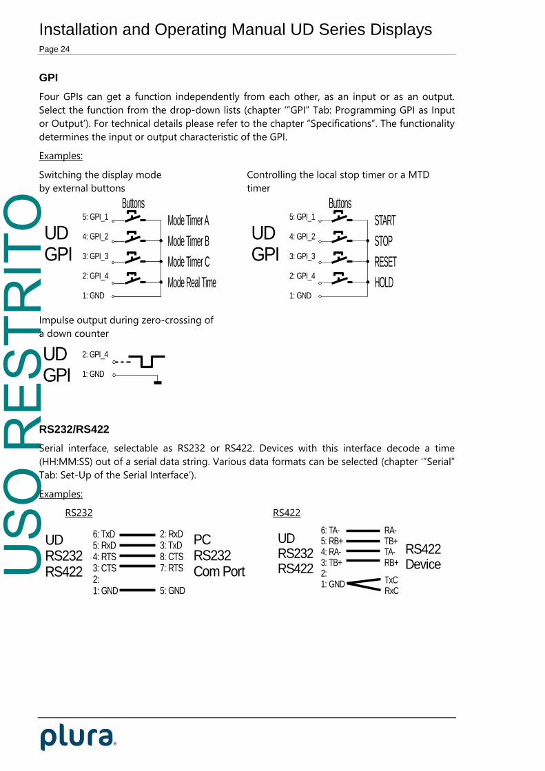
GPI
Four GPIs can get a function independently from each other, as an input or as an output.
Select the function from the drop-down lists (chapter ‘”GPI” Tab: Programming GPI as Input
or Output’). For technical details please refer to the chapter “Specifications”. The functionality
determines the input or output characteristic of the GPI.
Examples:
Switching the display mode Controlling the local stop timer or a MTD
by external buttons timer
UDGPI
Buttons5: GPI_1
4: GPI_2
3: GPI_3
2: GPI_4
1: GND
Mode Timer A
Mode Timer B
Mode Timer C
Mode Real Time
UDGPI
Buttons5: GPI_1
4: GPI_2
3: GPI_3
2: GPI_4
1: GND
START
STOP
RESET
HOLD
Impulse output during zero-crossing of
a down counter
UDGPI
2: GPI_4
1: GND
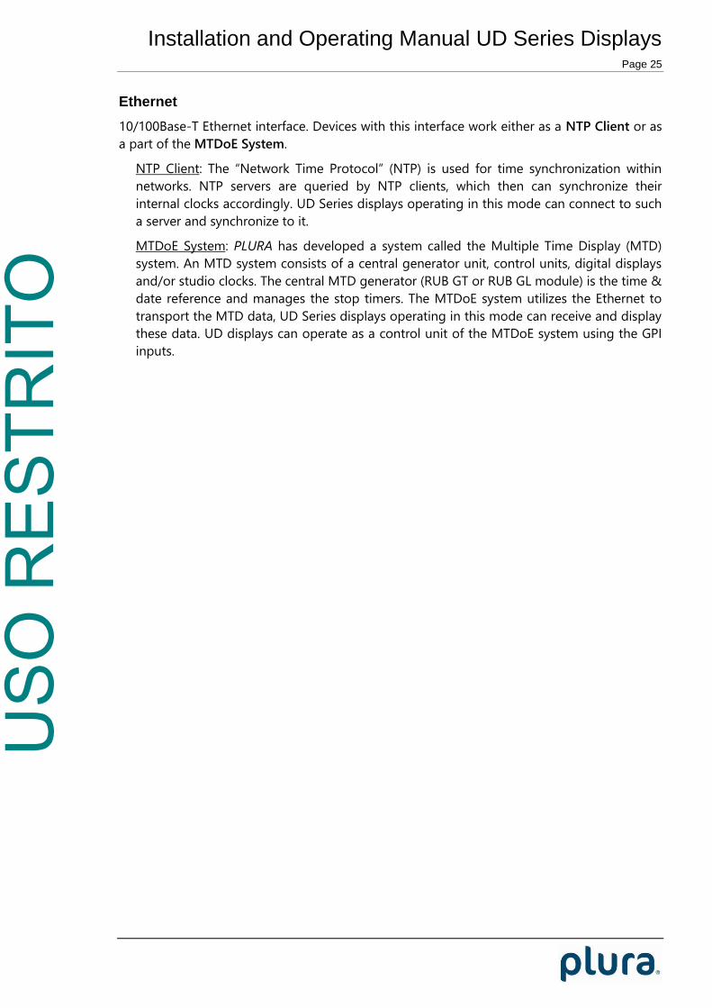
RS232/RS422
Serial interface, selectable as RS232 or RS422. Devices with this interface decode a time
(HH:MM:SS) out of a serial data string. Various data formats can be selected (chapter ‘”Serial”
Tab: Set-Up of the Serial Interface’).
Examples:
RS232 RS422
6: TxD5: RxD4: RTS3: CTS2:1: GND
2: RxD3: TxD8: CTS7: RTS
5: GND
PCRS232Com Port
UDRS232RS422
UDRS232RS422
6: TA-5: RB+4: RA-3: TB+2:1: GND
RA-TB+TA-RB+
TxCRxC
RS422Device
USO
RES
TRIT
O
Installation and Operating Manual UD Series Displays Page 25
Ethernet
10/100Base-T Ethernet interface. Devices with this interface work either as a NTP Client or as
a part of the MTDoE System.
NTP Client: The “Network Time Protocol” (NTP) is used for time synchronization within
networks. NTP servers are queried by NTP clients, which then can synchronize their
internal clocks accordingly. UD Series displays operating in this mode can connect to such
a server and synchronize to it.
MTDoE System: PLURA has developed a system called the Multiple Time Display (MTD)
system. An MTD system consists of a central generator unit, control units, digital displays
and/or studio clocks. The central MTD generator (RUB GT or RUB GL module) is the time &
date reference and manages the stop timers. The MTDoE system utilizes the Ethernet to
transport the MTD data, UD Series displays operating in this mode can receive and display
these data. UD displays can operate as a control unit of the MTDoE system using the GPI
inputs.

USO
RES
TRIT
O
Installation and Operating Manual UD Series Displays Page 26
Status after Power-On
Displays in LTC, IRIG or serial modes
After power-on the device performs a display test and indicates some status information:
Example Description
Digit 1 Digit 2 Digit 3 Digit 4 Digit 5 Digit 6
All LEDs will shortly light up with changing
colours.
Digit 1 Digit 2 Digit 3 Digit 4 Digit 5 Digit 6
Displaying the revision number, e.g. „1.21“.
Devices with two displays (for example of
type “UDD” or UD300D/UD300LD/UD300ED)
indicate a “1” at the first display and a “2” at
the second display at the 6th digit’s place.
Digit 1 Digit 2 Digit 3 Digit 4 Digit 5 Digit 6
Indicating the current display mode at digits
5 and 6, e.g.:
Digits Mode Source
∏ L Local Timer
г Г Time LTC(MTD)
г d Date LTC(MTD)
Г A Timer A LTC(MTD)
Г B Timer B LTC(MTD)
Г C Timer C LTC(MTD)
Г d Timer D LTC(MTD)
Г E Timer E LTC(MTD)
Г F Timer F LTC(MTD)
Г L LTC LTC(MTD)
∏ 1 Main Time 1 LTC(MTD)
∏ 2 Main Time 2 LTC(MTD)
∏ 3 Main Time 3 LTC(MTD)
L Г Time LTC
L d Date LTC
L U User LTC
S Г Time Serial
S d Date Serial
S S Status Serial
∏ S MTD Slave MTD Slave
USO
RES
TRIT
O
Installation and Operating Manual UD Series Displays Page 27
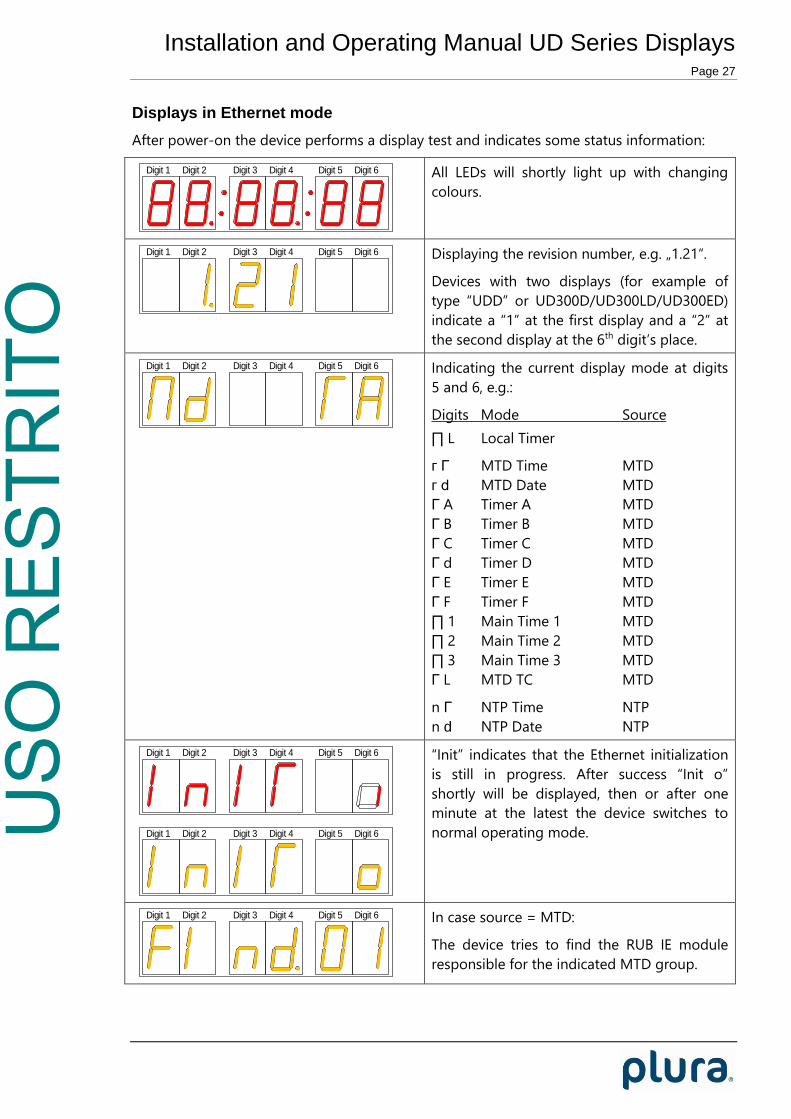
Displays in Ethernet mode
After power-on the device performs a display test and indicates some status information:
Digit 1 Digit 2 Digit 3 Digit 4 Digit 5 Digit 6
All LEDs will shortly light up with changing
colours.
Digit 1 Digit 2 Digit 3 Digit 4 Digit 5 Digit 6
Displaying the revision number, e.g. „1.21“.
Devices with two displays (for example of
type “UDD” or UD300D/UD300LD/UD300ED)
indicate a “1” at the first display and a “2” at
the second display at the 6th digit’s place.
Digit 1 Digit 2 Digit 3 Digit 4 Digit 5 Digit 6
Indicating the current display mode at digits
5 and 6, e.g.:
Digits Mode Source
∏ L Local Timer
г Г MTD Time MTD
г d MTD Date MTD
Г A Timer A MTD
Г B Timer B MTD
Г C Timer C MTD
Г d Timer D MTD
Г E Timer E MTD
Г F Timer F MTD
∏ 1 Main Time 1 MTD
∏ 2 Main Time 2 MTD
∏ 3 Main Time 3 MTD
Г L MTD TC MTD
n Г NTP Time NTP
n d NTP Date NTP
Digit 1 Digit 2 Digit 3 Digit 4 Digit 5 Digit 6
Digit 1 Digit 2 Digit 3 Digit 4 Digit 5 Digit 6
“Init” indicates that the Ethernet initialization
is still in progress. After success “Init o”
shortly will be displayed, then or after one
minute at the latest the device switches to
normal operating mode.
Digit 1 Digit 2 Digit 3 Digit 4 Digit 5 Digit 6
In case source = MTD:
The device tries to find the RUB IE module
responsible for the indicated MTD group.
USO
RES
TRIT
O
Installation and Operating Manual UD Series Displays Page 28
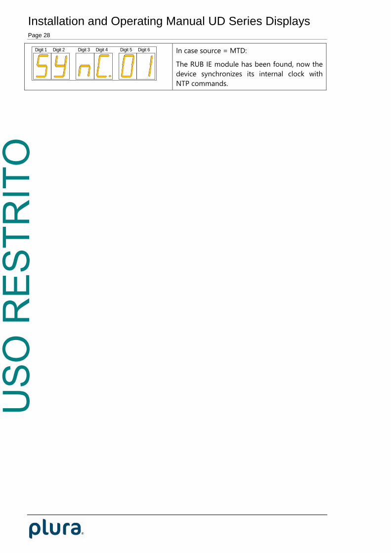
Digit 1 Digit 2 Digit 3 Digit 4 Digit 5 Digit 6
In case source = MTD:
The RUB IE module has been found, now the
device synchronizes its internal clock with
NTP commands.

USO
RES
TRIT
O
Installation and Operating Manual UD Series Displays Page 29
Firmware Update
Firmware updates require a (windows operating system) computer with a USB interface and
the UD SC Config.exe program. “Universal” and “E” version displays can also be updated over
Ethernet. You can download the latest version of the program from:
http://plura.tv/service/688
The new firmware should already be stored as a .tcf file at your computer.
Please now execute the following steps:
1. Connect the device to the computer with a standard USB cable (A – B type). It is recom-
mended not to have more than one device connected to this USB port.
2. Execute UD SC Config.exe on your computer. The program gives a list of all devices
found. Click (not a double click) on the device in the list which shows the USB
connection.
3. Select “Flash Update“ in the File menu.
4. Open the .tcf file. The program checks whether the new firmware matches the correct
type of the device. In case there is no match an error message appears: “Incompatible
Flash Update File”. Update starts automatically if everything is ok. Click the OK button at
the end.
5. Update is finished now. We recommend checking the configuration of the device.
During the flash update the operation of the device stops!
Displays in LTC mode:

USO
RES
TRIT
O
Installation and Operating Manual UD Series Displays Page 30
It is recommended to disconnect an existing RS485(MTD) connection before starting the flash
update. During the flash update the RS485 bus may be blocked!

USO
RES
TRIT
O
Installation and Operating Manual UD Series Displays Page 31
Configuration
The UD/SC Configuration Program
Configuration requires the UD SC Config.exe program running on a computer (32 or 64 bit
Windows operating system 2000/XP/2003/Vista/2008/7). You can download the latest
version of the program from:
http://plurabroadcast.com
Every UD device can be configured via a USB interface. “Universal” and “E” version displays
can be configured via Ethernet as well; the computer then must be connected to the network.
Access via Ethernet can be protected by a password (chapter “System Tab”). Firmware update
is performed by this program as well, but this requires the USB connection (chapter
“Firmware Update”).
USB connection requires a standard USB cable (A – B type). It is recommended but not
needed to have the device connected to an external power supply. If no power supply is
connected, the device can be configured as usual, but the device will stay in a shut-off mode,
regardless of current set-up. The first time the device is plugged to the PC, Windows will
install a driver for it. This driver is part of Windows, you don’t need a CD.
After program start a list is given of all devices found:
Open the configuration by marking the device on the list and pressing button “Configure”, or
by a double click on a device in the list. Additional tabs will be shown. On these tabs you can

USO
RES
TRIT
O
Installation and Operating Manual UD Series Displays Page 32
check or change the configuration of the selected device as described in the following
chapters.

USO
RES
TRIT
O
Installation and Operating Manual UD Series Displays Page 33
“Profile“ Tab: Store and Load a Complete Set-Up
This feature enables to easily change the complete set-up of the unit during normal
operation. During installation, the current set-up can be stored as a “profile”. You can enter a
name in the “name” entry before storing. Now choose a different set-up and store this as a
different profile. Fife profiles are available. Programming the GPI inputs with “Load Profile ...“
functions (please refer to chapter “GPI Tab: ...) enables you to change over from one set-up to
the other during normal operation.
Five different set-ups can be stored into
the non-volatile memory of the unit.
Click Store:
Profile: Select 1 – 5.
Info Operator: You may enter a text.
Comment: You may enter a text.
Click OK to store the current set-up.
Any set-up stored as a profile can replace
the current set-up.
Click Load:
Profile: Select “Factory Settings“ or 1 – 5.
“Factory Settings“ installs the
default set-up.
Click OK to replace the current set-up by
the selected profile. If no valid set-up has
USO
RES
TRIT
O
Installation and Operating Manual UD Series Displays Page 34
been stored, an error message is given.

USO
RES
TRIT
O
Installation and Operating Manual UD Series Displays Page 35
“System“ Tab: View and Change System Parameters
Unit
Name Give the device a significant name. This name appears wherever UD devices can
be found, either via Browser or via USB.
Enter a text (10 characters) in the Name field. Complete with Enter or Tab key.
Reboot Warm boot of the unit.
Security – available only for “universal” and “E” version displays
It is provided to protect the unit against non permission or unintentional access via Ethernet.
Any configuration with a USB connection ignores the password.
With a click on the Change button the following entry opens:
Enter the password twice and press the OK button.
Clear an existing password by checking No Password.
Password forgotten? → Please read chapter “Passwords” of “The MTD System” manual.
Info

USO
RES
TRIT
O
Installation and Operating Manual UD Series Displays Page 36
Indicates some device status, e.g. the version of the installed firmware.

USO
RES
TRIT
O
Installation and Operating Manual UD Series Displays Page 37
“Source” Tab: Select the Signal Source
“L” version displays: “E” version displays: “Universal” displays:
“Universal” or “L” version displays:
LTC(MTD) Please refer to chapter “Interfaces – LTC(MTD)“ as well. LTC(MTD) denotes a
special LTC format which contains real-time, date and various user selectable/-
configurable timers. Only this choice enables the device to use the extensive
functionality of the PLURA MTD system.
LTC Please refer to chapter “Interfaces – LTC(MTD)“ as well. With this operating
mode the device reads a standard LTC signal. The tabs “LTC“ and “Real-Time“
offer additional set-ups. Typical applications:
Simple LTC reader.
Real-time functionality with offset selection for different time zones.
Serial Please refer to chapter “Interfaces – RS232/RS422” as well. This operating
mode enables the serial interface. The tabs “Serial” and “Real-Time“ offer
additional set-ups. Typical applications:
Decoding a time out of a serial protocol and displaying HH:MM:SS.
Real-time functionality with offset selection for different time zones.
MTD Slave This selection enables a special Master-Slave operating mode described in
chapter “MTD Slave: Local Stop Timer and External Displays“.
“Universal” displays:
IRIG Please refer to chapter “Interfaces – IRIG“ as well. With this operating mode
the device reads a standard IRIG signal. The tabs “IRIG” and “Real-Time“ offer
additional set-ups. Typical applications:
Simple IRIG reader.
Real-time functionality with offset selection for different time zones.

USO
RES
TRIT
O
Installation and Operating Manual UD Series Displays Page 38
“Universal” and “E” version displays:
MTD The unit is able to decode and display all the timers of the MTD data. The MTD
data include six independent programmable timers, real-time, date, and a time
of a time code. Each timer can show a stop timer, a remaining time, a time
difference, a time of a time zone etc. UD displays can operate as a control unit
of the MTDoE system using the GPI inputs.
NTP The unit receives and displays a time & date. The received reference time can
get a programmable offset. It is possible to enable a Daylight Saving Time
handling.
USO
RES
TRIT
O
Installation and Operating Manual UD Series Displays Page 39
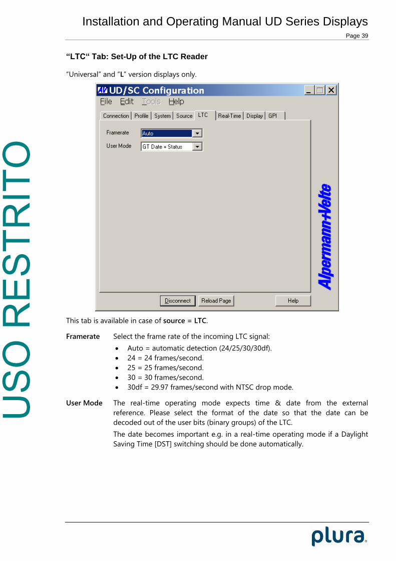
“LTC“ Tab: Set-Up of the LTC Reader
“Universal” and “L” version displays only.
This tab is available in case of source = LTC.
Framerate Select the frame rate of the incoming LTC signal:
Auto = automatic detection (24/25/30/30df).
24 = 24 frames/second.
25 = 25 frames/second.
30 = 30 frames/second.
30df = 29.97 frames/second with NTSC drop mode.
User Mode The real-time operating mode expects time & date from the external
reference. Please select the format of the date so that the date can be
decoded out of the user bits (binary groups) of the LTC.
The date becomes important e.g. in a real-time operating mode if a Daylight
Saving Time [DST] switching should be done automatically.
USO
RES
TRIT
O
Installation and Operating Manual UD Series Displays Page 40
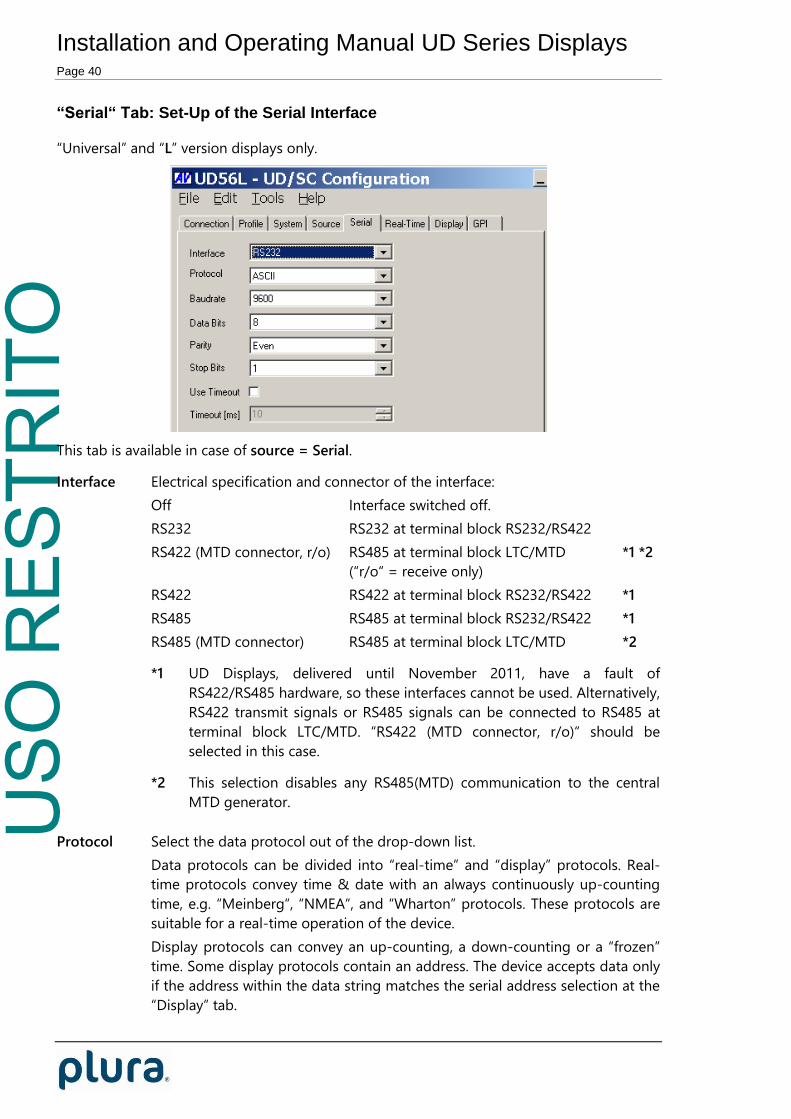
“Serial“ Tab: Set-Up of the Serial Interface
“Universal” and “L” version displays only.
This tab is available in case of source = Serial.
Interface Electrical specification and connector of the interface:
Off Interface switched off.
RS232 RS232 at terminal block RS232/RS422
RS422 (MTD connector, r/o) RS485 at terminal block LTC/MTD *1 *2
(“r/o“ = receive only)
RS422 RS422 at terminal block RS232/RS422 *1
RS485 RS485 at terminal block RS232/RS422 *1
RS485 (MTD connector) RS485 at terminal block LTC/MTD *2
*1 UD Displays, delivered until November 2011, have a fault of
RS422/RS485 hardware, so these interfaces cannot be used. Alternatively,
RS422 transmit signals or RS485 signals can be connected to RS485 at
terminal block LTC/MTD. “RS422 (MTD connector, r/o)“ should be
selected in this case.
*2 This selection disables any RS485(MTD) communication to the central
MTD generator.
Protocol Select the data protocol out of the drop-down list.
Data protocols can be divided into “real-time” and “display” protocols. Real-
time protocols convey time & date with an always continuously up-counting
time, e.g. “Meinberg“, “NMEA“, and “Wharton” protocols. These protocols are
suitable for a real-time operation of the device.
Display protocols can convey an up-counting, a down-counting or a “frozen”
time. Some display protocols contain an address. The device accepts data only
if the address within the data string matches the serial address selection at the
“Display” tab.

USO
RES
TRIT
O
Installation and Operating Manual UD Series Displays Page 41
Please refer to document “UD Series Displays: Serial Protocols“ for a detailed
description. You can download this document from:
http://plurabroadcast.com

USO
RES
TRIT
O
Installation and Operating Manual UD Series Displays Page 42
Baud rate Choose the baud rate:
2.400 / 4.800 / 9.600 / 19.200 / 38.400 / 57.600 / 115.200
Data Bits 7 or 8 data bits.
Parity Select the parity mode:
None Without parity
Even Even parity bit
Odd Odd parity bit
Stop Bits 1 or 2 stop bits.
Use Timeout ASCII based protocols in general use STX/ETX or similar control characters to
synchronize the communication. Other protocols may use a timeout for this
purpose. In this case, the receiver expects a start of a new data string if for the
time of the timeout value [in milliseconds] no data has been received.
Select a suitable Timeout value dependent on baud rate and frequency of the
data. Recommendation:
Baud rate Timeout [ms] Timeout [ms]
Data string per second Data string per frame
2400 100 -
4800 100 -
9600 100 6
19200 100 11
≥ 38400 100 14

USO
RES
TRIT
O
Installation and Operating Manual UD Series Displays Page 43
“Ethernet“ Tab: IP Addresses ...
“Universal” and “E” version displays only.
“Source = MTD“ “Source = NTP“:
Current Settings
This box indicates the current network parameters of the device.
A click on Change... enables to change parameters:
Use DHCP If checked, the device will automatically request its IP parameters (IP address,
subnet mask, and gateway) from a DHCP server. In this case the “IP Address”,
“Subnet Mask”, and “Gateway” boxes have no relevance.
Please let the device restart (power off – on) if you select this mode.
USO
RES
TRIT
O
Installation and Operating Manual UD Series Displays Page 44
MTD - if “Source = MTD“ has been selected
Automatic MTD Master IP Address If checked, the device will automatically find the
MTDoE central unit responsible for the group number below. In a
redundant system (two MTDoE central units), an automatic changeover can
take place in case one central unit fails.
Restriction: The automatic mode requires that this unit and the MTDoE
central unit are in the same local network. If the units are
connected to different local networks, the IP addresses (of
‘Primary MTD Master’ and – if present – ‘Secondary MTD
Master’) have to be entered manually.
Primary MTD Master IP Address If “Automatic MTD Master IP Address” is not checked,
the IP address of the MTDoE central unit has to be entered manually.
Secondary MTD Master IP Address It is possible to have a redundancy of MTDoE central
units. A second MTDoE central unit then is working in the same MTDoE
system (it operates with the same MTDoE group number). If “Automatic
MTD Master IP Address” is not checked, the IP address of the second
MTDoE central unit has to be entered manually.
Group Indicates the MTDoE group number. Likewise, you can change this number
here.
Click Reload Page at the bottom of the tab if the „Current Settings“ box does not show the
new parameters.
NTP Client - if “Source = NTP“ has been selected
Enter the IP addresses which the NTP client of the device uses to request time & date
information of an NTP server.
Primary Server IP Address Address of the primary (1st) NTP server.
Secondary Server IP Address Address of a secondary (back-up) NTP Server.
Click Reload Page at the bottom of the tab if the „Current Settings“ box does not show a
changed address.
USO
RES
TRIT
O
Installation and Operating Manual UD Series Displays Page 45
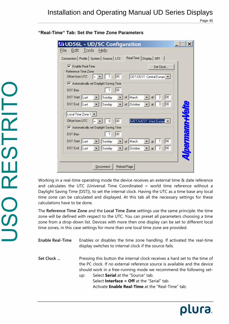
“Real-Time“ Tab: Set the Time Zone Parameters
Working in a real-time operating mode the device receives an external time & date reference
and calculates the UTC (Universal Time Coordinated = world time reference without a
Daylight Saving Time [DST]), to set the internal clock. Having the UTC as a time base any local
time zone can be calculated and displayed. At this tab all the necessary settings for these
calculations have to be done.
The Reference Time Zone and the Local Time Zone settings use the same principle: the time
zone will be defined with respect to the UTC. You can preset all parameters choosing a time
zone from a drop-down list. Devices with more then one display can be set to different local
time zones, in this case settings for more than one local time zone are provided.
Enable Real-Time Enables or disables the time zone handling. If activated the real-time
display switches to internal clock if the source fails.
Set Clock ... Pressing this button the internal clock receives a hard set to the time of
the PC clock. If no external reference source is available and the device
should work in a free-running mode we recommend the following set-
up: Select Serial at the “Source” tab.
Select Interface = Off at the “Serial” tab.
Activate Enable Real-Time at the “Real-Time” tab.
USO
RES
TRIT
O
Installation and Operating Manual UD Series Displays Page 46

USO
RES
TRIT
O
Installation and Operating Manual UD Series Displays Page 47
Time zone parameters separately for Reference Time Zone and Local Time Zone
You can choose a time zone from this drop-down list. This will
preset all parameters.
Offset from UTC Standard time (winter time) = UTC ± offset (HH:MM).
Automatically set Daylight Saving Time
Check this box if the reference input has a DST period.
If the time zone has a DST period the following parameters should be selected:
DST Bias Enter the DST correction value. Most of the cases the correction value will be (+)
one hour.
DST Start Using these inputs (e.g. last Sunday of March at 2 o’clock) the device calculates
the start of DST for the current year.
DST End Using these inputs (e.g. last Sunday of October at 3 o’clock) the device calculates
the end of DST for the current year.

USO
RES
TRIT
O
Installation and Operating Manual UD Series Displays Page 48
“Display“ Tab: Display Mode, Brightness, ...
This tab enables to specify in detail which data will be displayed and how. Devices with two
displays can be set separately; in this case two tabs will be shown:
At UDD25: Left Display (1) and Right Display (2).
At UD300D/UD300LD/UD300ED: Main Display (1) and Appended Display (2).
Mode Operating modes of the display – dependent on “Source” selection:
Mode Description available for
„Source =...“
Local Local (internal) stop timer, controlled via GPI functions. No
other external signal is required.
LTC(MTD)
LTC, IRIG,
Serial,
MTD, NTP
(MTD) Time
(MTD) Date
Unit displays real-time or date – decoded out of the MTD
data.
LTC(MTD)
MTD
(NTP) Time Time display with selectable 12-hour or 24-hour format (see
below). This mode can be extended to a “real-time” mode –
see description of the Time Zone setting below.
LTC, IRIG,
Serial, NTP
(NTP) Date Date display with selectable Day/Month/Year format (see
below).
LTC, IRIG,
Serial, NTP
Timer A ... F Display of time A (... time F) decoded out of the LTC(MTD),
e.g. stop timer A (... F).
LTC(MTD)
MTD
Main 1 ... 3 “Main Time 1” (... 3) decoded out of the LTC(MTD). LTC(MTD)
MTD
TC/LTC Time addresses of the time code of the central MTD
generator.
LTC(MTD)
MTD
USO
RES
TRIT
O
Installation and Operating Manual UD Series Displays Page 49
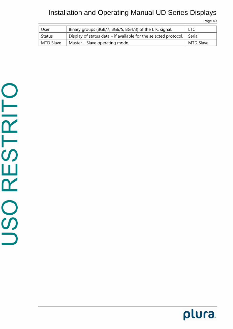
User Binary groups (BG8/7, BG6/5, BG4/3) of the LTC signal. LTC
Status Display of status data – if available for the selected protocol. Serial
MTD Slave Master – Slave operating mode. MTD Slave

USO
RES
TRIT
O
Installation and Operating Manual UD Series Displays Page 50
Brightness
Digits Brightness of the display: 7 steps, 7 = maximum brightness.
Ring Units with a seconds ring only: brightness of the seconds ring. With lock
clicked the brightness of the seconds ring follows the brightness of the
digits.
Test Displays All LEDs will light-up for test purposes.
Format
Color LED colour:
Auto If “Source = LTC(MTD)” or “Source = MTD”:
The display decodes the colour out of the MTD data.
Red/Yellow/Green
Delimiter Separating sign between pairs of digits:
Auto If “Source = LTC(MTD)” or “Source = MTD”:
The display decodes the separating sign out of the MTD
data.
Off No separating sign.
Decimal Points
Colon
Time HH:MM:SS 24h Time display in a 24-hour format.
HH:MM:SS 12h Time display in a 12-hour format.
Date YY MM DD Year / Month / Day.
MM DD YY Month / Day / Year.
DD MM YY Day / Month / Year.
MM YYYY Month / Year 4-digits format.
Time Zone This set-up defines your real-time operating mode together with the set-up at
the Real-Time tab.
Time Zone Enable Real-Time at
the Real-Time tab
Description
Off Not checked Displays the time of the source without offset
calculation. Time display stops if the source fails.
Off Checked Displays the time of the source +/- offset
according to “Reference Time Zone” set-up.
Time display continues if the source fails.
Time Zone 1
Time Zone 2
Checked The time of the source will be corrected with the
offset according to “Reference Time Zone“ set-
up. This time base +/- offset according to „Local
Time Zone“ will be the time displayed. Time
display continues if the source fails.
Serial

USO
RES
TRIT
O
Installation and Operating Manual UD Series Displays Page 51
Address Some serial data protocols may contain an address. The device accepts the
data only if the address matches the serial address selection at this tab. If
the device has more than one display each gets its own address.

USO
RES
TRIT
O
Installation and Operating Manual UD Series Displays Page 52
“GPI“ Tab: Programming GPI as Input or Output
Four GPIs can get a function independently from each other, as an input or as an output.
Select the function from the drop-down lists. For technical details please refer to chapter
“Specifications”. The input or output mode of the GPI will be determined by the selected
function.
No Operation GPI has no function.
GPI Inputs
Selecting any input function will activate the “mode” box:
Mode: “Active Low“ (please refer to chapter “Specifications“ for technical details).
GPI Input1: GND
Example: Function becomes active if input state
changes from “open” to “closure to GND”.
“Active High“ (please refer to chapter “Specifications“ for technical details).
GPI Input1: GND
Example: Function becomes active if input state
changes from “closure to GND” to “open”.
If one GPI input has “Mode = Active Low” and another “Mode = Active High”,
both functions can be executed alternatively with only one signal:

USO
RES
TRIT
O
Installation and Operating Manual UD Series Displays Page 53
Function 1
GPI_1: Active LowGPI_2: Active High1: GND
GPI_1: Active LowGPI_2: Active High1: GND
Function 2
Function Description
Start
Stop
Reset
Hold
Start/Stop
Reset+Start
Reset+Continue
These commands come in effect only if the device displays any
timer: local timer (independent on “Source” selection) or any MTD
timer A ... F (in this case, displays in mode LTC(MTD) should have
the RS485 at MTD terminal block connected to the central MTD
generator).
At devices with two displays (UDD25, UD300D, UD300LD,
UD300ED) only the 1st display will be controlled.
Start Timer starts.
Stop Timer stops.
Reset Timer stops and will be set to zero.
Hold Display “freezes” the timer value, timer keeps
running.
Start/Stop Alternating commands.
Reset+Start Reset command followed by a Start command.
Reset+Continue “Reset” if selected timer stays in stop mode.
“Reset+Start” if selected timer is running.
Toggle Display
UD with 2 Displays:
Toggle Displays
Toggle Display 1
Toggle Display 2
Switches the display on/off alternating.
In “off” state, one decimal point will light up weakly to indicate that
the unit is operating.
Switch Display Off
UD with 2 Displays:
Switch Displays Off
Switch Display 1 Off
Switch Display 2 Off
Switches the display on/off by use of an external switch.
If “Mode = Active Low”, a closure to ground or a “Low” state will
turn the display “off” (one decimal point will light up weakly to
indicate that the unit is operating); switch open or a “High” state
will turn the display “on”.
Next Display Mode
UD with 2 Displays:
Display 1: Next ...
Display 2: Next ...
Switches the display to the next mode - according to the “Mode”
drop-down list at the “Display” tab. The available modes are
depended on the source selection. After switching, the display
shortly indicates the selected mode.
Previous Display
Mode
UD with 2 Displays:
Display 1: Previous...
Display 2: Previous...
Switches the display to the previous mode - according to the
“Mode” drop-down list at the “Display” tab. The available modes
are depended on the source selection. After switching, the display
shortly indicates the selected mode.
--- Main Timer ---
Main 1 = Time
Main 1 = Date
Main 1 = Timer A
Main 1 = Timer B
Main 1 = Timer C
Switches the „Main“ timers: Main 1, Main 2, Main 3.
Conditions:
LTC(MTD): “Source = LTC(MTD)“, and RS485 at MTD terminal block
connected to the central MTD generator.

USO
RES
TRIT
O
Installation and Operating Manual UD Series Displays Page 54
Main 1 = Timer D
Main 1 = Timer E
Main 1 = Timer F
Main 2 = Time
. . .
Main 3 = Time
. . .
Ethernet: “Source = MTD“.
Features of the “Main” timers are described in:
“The MTD System – Installation and Operation Manual”.
PPS Input If “Source = Serial” only: GPI will be configured as a pulse-per-
second input.
Display Mode ...
UD with 2 Displays:
Display 1 Mode: ...
Display 2 Mode: ...
Selecting display modes directly. The available modes are
depended on the source selection. The new display mode will not
be stored internally, i.e. after powering on the unit the display
selects that mode which has been set by the configuration program
(at “Display” tab).

USO
RES
TRIT
O
Installation and Operating Manual UD Series Displays Page 55
Profiles
Load Profile 1
Load Profile 2
Load Profile 3
Load Profile 4
Load Profile 5
The “Load Profile” function enables to change the complete set-up
in a comfortable way.
Please notice chapter “Profile Tab: ...“ as well.
Please remember to program all GPI functions correctly before you
execute a “Store Profile”.
Example 1: Four different signals/buttons recall four different set-
ups. Each set-up has all GPIs configured as follows:
GPI 1 = Load Profile 1, “Mode = Active Low“;
GPI 2 = Load Profile 2, “Mode = Active Low“;
GPI 3 = Load Profile 3, “Mode = Active Low“;
GPI 4 = Load Profile 4, “Mode = Active Low“.
5: GPI_14: GPI_23: GPI_32: GPI_41: GND
Load Profile 1
Load Profile 4Load Profile 3Load Profile 2
Example 2: One signal/switch changes over from first set-up to
second. Both set-ups have GPIs configured as follows:
GPI 1 = Load Profile 1, “Mode = Active High“;
GPI 2 = Load Profile 2, “Mode = Active Low“.
Switch open: Switch closed:
5: GPI_14: GPI_21: GND
Load Profile 1
5: GPI_14: GPI_21: GND
Load Profile 2
Example 3: One signal/button recalls five different set-ups one
after another. The set-ups have GPIs configured as
follows:
Profile 1: GPI 1 = Load Profile 2, “Mode = Active Low“.
Profile 2: GPI 1 = Load Profile 3, “Mode = Active Low“.
Profile 3: GPI 1 = Load Profile 4, “Mode = Active Low“.
Profile 4: GPI 1 = Load Profile 5, “Mode = Active Low“.
Profile 5: GPI 1 = Load Profile 1, “Mode = Active Low“.
5: GPI_11: GND

USO
RES
TRIT
O
Installation and Operating Manual UD Series Displays Page 56
GPI Outputs
GPI OUT functions work as a time comparator. A fixed time value entered at the compare to
entries will be compared with the time of the display or the time of a selected timer. A match
leads to an impulse output. The pulse duration is adjustable.
Selecting any output function will activate the “compare to” and “mode” boxes:
compare to: Select hours (0–23) : minutes (0–59) : seconds (0–59).
Mode: “Active Low“ or “Active High“ mode, please refer to chapter “Specifications.
The GPI OUT drop-down list offers different functions depending on the selection at
“Source”. The “Display“ function compares the current time shown at the display. All other
functions compare the selected timer or the selected time – no matter of the display mode.
Functions – dependent on “Source” selection:
Function Description available for
“Source = ...“
Display
UD with 2 Displays:
Display 1
Display 2
Comparison with the time currently shown at the
display.
LTC(MTD)
LTC, IRIG, Serial,
MTD Slave,
MTD, NTP
Local Comparison with the local (internal) stop timer. LTC(MTD)
LTC, IRIG, Serial,
MTD Slave,
MTD, NTP
Real-Time Comparison with the real-time decoded out of the
MTD data.
LTC(MTD)
MTD
Time Comparison with the received time. LTC, IRIG, Serial
MTD Slave
NTP
Time Zone 1
Time Zone 2
If a real-time operating mode has been selected:
Comparison with the time of the selected time
zone.
LTC, IRIG, Serial
NTP
Timer A ... F Comparison with the selected MTD timer A ... F. LTC(MTD)
MTD
Main 1 ... 3 Comparison with the selected MTD “main time” 1
... 3.
LTC(MTD)
MTD
MTD TC Comparison with the time addresses of the time
code of the central MTD generator.
LTC(MTD)
MTD

USO
RES
TRIT
O
Installation and Operating Manual UD Series Displays Page 57
Pulse Duration
GPI output: Pulse duration 100/200/500 ms, 1 second, or 2 seconds.

USO
RES
TRIT
O
Installation and Operating Manual UD Series Displays Page 58
Special Features
Colour Changing Modes
Configuration “Color = Auto” at the Display tab.
If “Source = LTC(MTD)” or “Source = MTD” has been selected: The display decodes the colour
of the LED’s out of the MTD Data. These data contain status data which set the LED colour. At
the central MTD time code generator the colour can be selected and a dynamic change of
colour at special events can be realized. For example the following features can be
programmed at the MTD time code generator:
Select the basic colour: red, yellow or green.
Activate a colour changing mode: - No colour changing mode.
- Change colour in case of a minus sign, new
colour can be red, yellow or green.
- Change colour in case of time ≥ 12 o’clock (PM
time), new colour can be red, yellow or green.
This feature is not available for displays of type UD126 and UD178. This is a standard feature
for all other UD Series displays.
USO
RES
TRIT
O
Installation and Operating Manual UD Series Displays Page 59
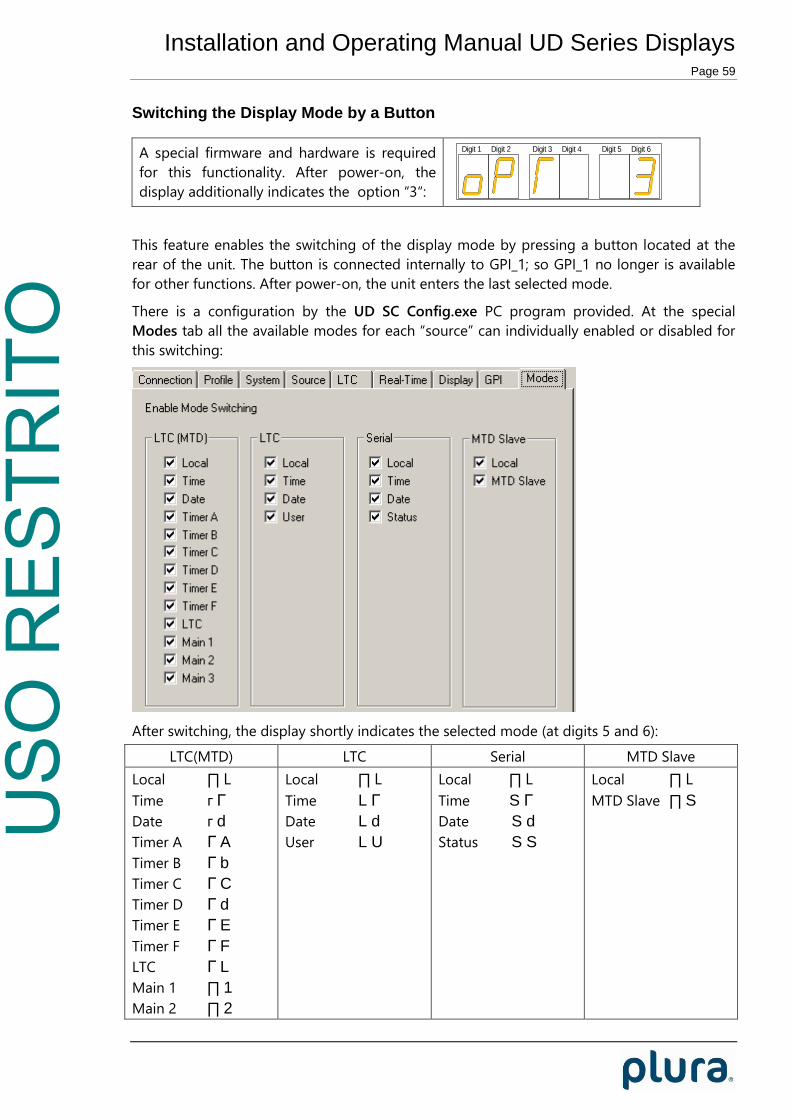
Switching the Display Mode by a Button
A special firmware and hardware is required
for this functionality. After power-on, the
display additionally indicates the option “3“:
Digit 1 Digit 2 Digit 3 Digit 4 Digit 5 Digit 6
This feature enables the switching of the display mode by pressing a button located at the
rear of the unit. The button is connected internally to GPI_1; so GPI_1 no longer is available
for other functions. After power-on, the unit enters the last selected mode.
There is a configuration by the UD SC Config.exe PC program provided. At the special
Modes tab all the available modes for each “source” can individually enabled or disabled for
this switching:
After switching, the display shortly indicates the selected mode (at digits 5 and 6):
LTC(MTD) LTC Serial MTD Slave
Local ∏ L
Time г Г
Date г d
Timer A Г A
Timer B Г b
Timer C Г C
Timer D Г d
Timer E Г E
Timer F Г F
LTC Г L
Main 1 ∏ 1
Main 2 ∏ 2
Local ∏ L
Time L Г
Date L d
User L U
Local ∏ L
Time S Г
Date S d
Status S S
Local ∏ L
MTD Slave ∏ S
USO
RES
TRIT
O
Installation and Operating Manual UD Series Displays Page 60
Main 3 ∏ 3
USO
RES
TRIT
O
Installation and Operating Manual UD Series Displays Page 61
Technical Data
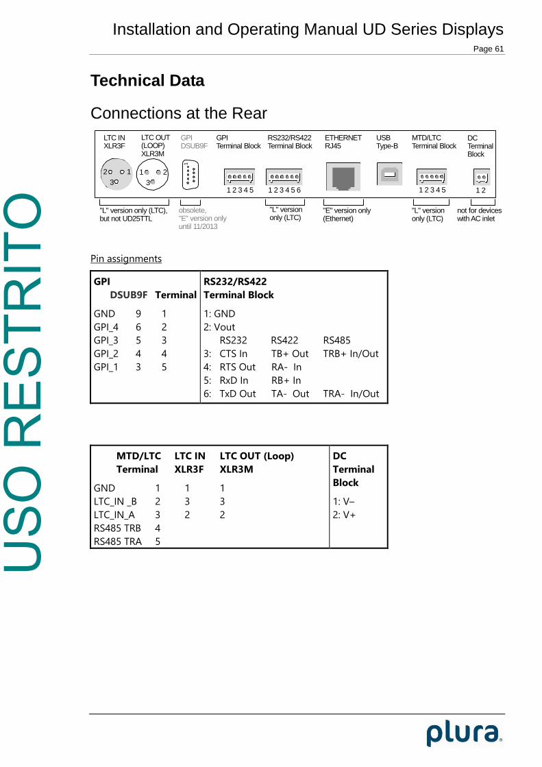
Connections at the Rear
1 21 2 3 4 51 2 3 4 5 61 2 3 4 51
12
3
21
3
LTC INXLR3F
LTC OUT(LOOP)XLR3M
GPIDSUB9F
RS232/RS422Terminal Block
GPITerminal Block
ETHERNETRJ45
USBType-B
MTD/LTCTerminal Block
DCTerminalBlock
not for deviceswith AC inlet
"L" versiononly (LTC)
"E" version only(Ethernet)
"L" versiononly (LTC)
"L" version only (LTC),but not UD25TTL
obsolete,"E" version onlyuntil 11/2013
Pin assignments
GPI
DSUB9F Terminal
GND 9 1
GPI_4 6 2
GPI_3 5 3
GPI_2 4 4
GPI_1 3 5
RS232/RS422
Terminal Block
1: GND
2: Vout
RS232 RS422 RS485
3: CTS In TB+ Out TRB+ In/Out
4: RTS Out RA- In
5: RxD In RB+ In
6: TxD Out TA- Out TRA- In/Out
MTD/LTC LTC IN LTC OUT (Loop)
Terminal XLR3F XLR3M
GND 1 1 1
LTC_IN _B 2 3 3
LTC_IN_A 3 2 2
RS485 TRB 4
RS485 TRA 5
DC
Terminal
Block
1: V–
2: V+

USO
RES
TRIT
O
Installation and Operating Manual UD Series Displays Page 62
Signal descriptions
GND Signal ground.
GPI_1, GPI_2
GPI_3, GPI_4
Programmable General Purpose Interfaces: Inputs or Outputs.
Vout DC voltage output.
ATTENTION: Using “Vout” please make sure not to exceed the
total power rating of the connected Power Supply adapter.
CTS, RTS, RxD, TxD Inputs and outputs of the serial interface in the RS232 operating
mode: “Interface = RS232” has been selected at the Serial
configuration.
TB+, RA-, RB+, TA- Inputs and outputs of the serial interface in the RS422 operating
mode: “Interface = RS422” has been selected at the Serial
configuration.
TRB+, TRA- Inputs and outputs of the serial interface in the RS485 operating
mode: “Interface = RS485” has been selected at the Serial
configuration.
LTC_IN_A, LTC_IN_B Balanced LTC (Linear Time Code) or IRIG input. The LTC OUT
signals at the XLR connector are just hard-wired to LTC input
signals.
RS485 TRA, RS485 TRB Balanced in- or outputs of a RS485 serial interface.
This interface is preferably used for communication in the MTD
system.
V–, V+ Power supply input:
V– = GND
V+ = DC voltage input

USO
RES
TRIT
O
Installation and Operating Manual UD Series Displays Page 63
Specifications
LTC input
Format According to ANSI/SMPTE 12M-1-2008, balanced
Input impedance 18 k
Signal level 50 mVp-p to 5 Vp-p, auto-ranging
Frequency 21–33 frames/s
IRIG input
Format Modulated 1 kHz carrier signal, unbalanced
IRIG-B 123 or IRIG-B 127 according to IRIG STANDARD 200-04
AFNOR time code according to AFNOR NF S 87-500
Input impedance 18 k
Signal level 200 mVp-p to 4 Vp-p, auto-ranging (“Mark” amplitude)
RS485 at LTC/MTD connector
RS485(MTD) Format 9600/8/E/1
Ethernet
Medium 10Base-T or 100Base-T, automatic detection
CTS/RXD inputs at RS232/RS422 connector
Voltage range -15 to +15 V
Threshold “Low” +0.8 V minimum
Threshold “High” +2.4 V maximum
Impedance ≈ 5 kΩ typical
GPI
Input specification Voltage range: –20 to +20 V
Threshold “Low”: +0.7 V minimum
Threshold “High”: +2.0 V maximum
Impedance: ≈ 24 kΩ typical
Frequency: 0–10 kHz
Output specification Open Collector output of a NPN Darlington transistor.
Internal 33 k pull-up resistor.
Max. power dissipation: 250 mW.
“High“ state: 2.4 V (no load). For higher switching levels an external
pull-up to a positive power source of less than or equal to 24 VDC is
needed, typically 1 kΩ when connected to an external +5 VDC power
source.
“Low“ state: output switched to GND.
Max. collector current: 200 mA DC, not fused.

USO
RES
TRIT
O
Installation and Operating Manual UD Series Displays Page 64
Collector-emitter saturation voltage:
@ 20 mA: typical 0.72 V ( 0.85 V)
@ 100 mA: typical 0.9 V ( 1.1 V)
Frequency: 0–1 kHz
Vout
Output of the DC
power supply
Reversible fused. A continuous current of up to 120 mA can be
applied over the whole specified operating temperature range. At an
ambient temperature of e.g. 22 °C the output switches to a high-
resistance state after a few seconds if a current of 400 mA is applied.
Free-run accuracy
Real-time operating modes ≈ 3 ppm (deviation ± 260 ms each day)
Local timer operating
mode
≈ 50 ppm (deviation ± 1 second within 5½ hours)
Other common specifications
Environmental characteristics,
operating
Temperature: +5 °C to +40 °C
Relative humidity: 30 % to 85 %, non-condensing
Environmental characteristics,
non-operating
Temperature: –10 °C to +60 °C
Relative humidity: 5 % to 95 %, non-condensing
Operating voltage and power consumption
Model Operating voltage
DC (option UD-EP)
Operating voltage AC Power consumption
UD25... V+: 10–30 VDC
(*)
Option UD-AP:
88–264 VAC/47–63 Hz
≈ 6 W
UDD25... V+: 10–30 VDC
(*)
Option UD-AP:
88–264 VAC/47–63 Hz
≈ 12 W
UD56, UD56L, UD56E V+: 15–30 VDC
(*)
Option UD-BP:
88–264 VAC/47–63 Hz
≈ 8 W
UD56S, UD56LS,
UD56ES
V+: 15–30 VDC
(*)
Option UD-BP:
88–264 VAC/47–63 Hz
≈ 15 W
UD300, UD300L,
UD300E
90–264 VAC/47–63 Hz ≈ 22 W
UD300D, UD300LD,
UD300ED
90–264 VAC/47–63 Hz ≈ 25 W
UD126... 85–264 VAC/47–63 Hz ≈ 35 W
UD178... 85–264 VAC/47–63 Hz ≈ 40 W
* If power is supplied via PoE and DC simultaneously, DC should be in the range of 24–30 V.
Readability of the display up to a distance of ...

USO
RES
TRIT
O
Installation and Operating Manual UD Series Displays Page 65
Version maximum distance
UD25..., UDD25... 10 m
UD56... 22 m
UD300... 22 m
UD300 attached display 10 m
UD126... 50 m
UD178... 60 m
USO
RES
TRIT
O
Installation and Operating Manual UD Series Displays Page 66
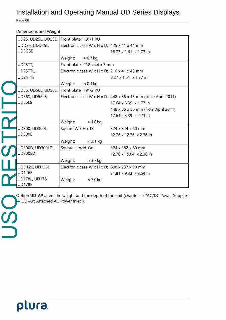
Dimensions and Weight
UD25, UD25L, UD25E,
UDD25, UDD25L,
UDD25E
Front plate: 19“/1 RU
Electronic case W x H x D: 425 x 41 x 44 mm
16.73 x 1.61 x 1.73 in
Weight: ≈ 0.7 kg
UD25TT,
UD25TTL,
UD25TTE
Front plate: 212 x 44 x 3 mm
Electronic case W x H x D: 210 x 41 x 45 mm
8.27 x 1.61 x 1.77 in
Weight: ≈ 0.4 kg
UD56, UD56L, UD56E,
UD56S, UD56LS,
UD56ES
Front plate 19“/2 RU
Electronic case W x H x D: 448 x 86 x 45 mm (since April 2011)
17.64 x 3.39 x 1.77 in
448 x 86 x 56 mm (from April 2011)
17.64 x 3.39 x 2.21 in
Weight: ≈ 1.0 kg
UD300, UD300L,
UD300E
Square W x H x D: 324 x 324 x 60 mm
12.76 x 12.76 x 2.36 in
Weight: ≈ 3,1 kg
UD300D, UD300LD,
UD300ED
Square + Add-On: 324 x 382 x 60 mm
12.76 x 15.04 x 2.36 in
Weight: ≈ 3.7 kg
UDD126, UD126L,
UD126E
UD178L, UD178,
UD178E
Electronic case W x H x D: 808 x 237 x 90 mm
31.81 x 9.33 x 3.54 in
Weight: ≈ 7.0 kg
Option UD-AP alters the weight and the depth of the unit (chapter → “AC/DC Power Supplies
→ UD-AP: Attached AC Power Inlet”).

USO
RES
TRIT
O
Installation and Operating Manual UD Series Displays Page 67
AC/DC Power Supplies
UD-EP: External Power Adapter
The “UD-EP” AC/DC adapter is an accessory for the PLURA UD Series Displays.
It has a fully enclosed plastic case, a three pole AC inlet according to IEC/EN 60320-1/C14
protection class 1, and a DC output cable with a jack suitable to connect to the DC terminal
block of the UD display. The power supply cord must match the AC outlet of your country
and is not part of the delivery.
Please notice the following specifications:
Input 100–240 VAC / 0.6 A / 47–63 Hz
Output 24 VDC, 850 mA, 20 W max.
Length of output cable 115 cm / 45.3 in
Dimension (W x H x D) 50 x 30 x 110 mm / 1.97 x 1.18 x 4.33 in
Weight 165 g (incl. output cable)
Environment Operating: Temp. +0 °C to +40 °C, humidity 20 % to 80 %
Storage: Temp. –20 °C to +85 °C, humidity 10 % to 95 %
Safety standards EN60950, UL listed
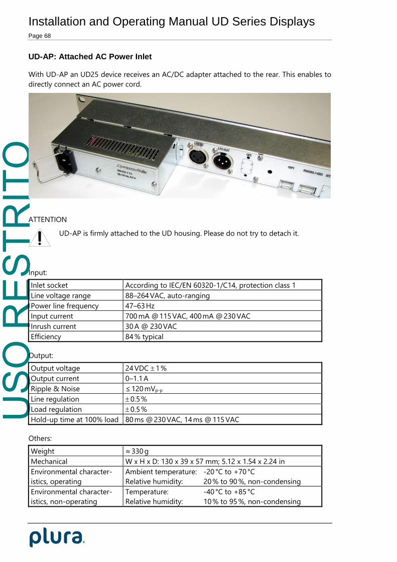
USO
RES
TRIT
O
Installation and Operating Manual UD Series Displays Page 68
UD-AP: Attached AC Power Inlet
With UD-AP an UD25 device receives an AC/DC adapter attached to the rear. This enables to
directly connect an AC power cord.
ATTENTION
UD-AP is firmly attached to the UD housing. Please do not try to detach it.
Input:
Inlet socket According to IEC/EN 60320-1/C14, protection class 1
Line voltage range 88–264 VAC, auto-ranging
Power line frequency 47–63 Hz
Input current 700 mA @ 115 VAC, 400 mA @ 230 VAC
Inrush current 30 A @ 230 VAC
Efficiency 84 % typical
Output:
Output voltage 24 VDC 1 %
Output current 0–1.1 A
Ripple & Noise ≤ 120 mVp-p
Line regulation 0.5 %
Load regulation 0.5 %
Hold-up time at 100% load 80 ms @ 230 VAC, 14 ms @ 115 VAC
Others:
Weight ≈ 330 g
Mechanical W x H x D: 130 x 39 x 57 mm; 5.12 x 1.54 x 2.24 in
Environmental character-
istics, operating
Ambient temperature: -20 °C to +70 °C
Relative humidity: 20 % to 90 %, non-condensing
Environmental character-
istics, non-operating
Temperature: -40 °C to +85 °C
Relative humidity: 10 % to 95 %, non-condensing

USO
RES
TRIT
O
Installation and Operating Manual UD Series Displays Page 69
Safety standards UL60950-1, EN60950-1

USO
RES
TRIT
O
Installation and Operating Manual UD Series Displays Page 70
UD-BP: Integrated AC Power Inlet
With UD-BP an UD56 device receives an integrated AC/DC adapter. This enables to directly
connect an AC power cord.
12
3
21
3
1 2 3 4 51 2 3 4 5 61 2 3 4 5
1
XLR3FLTC IN
XLR3MLTC OUT(LOOP)
GPIGPIRS232RS422 ETHERNET USB LTC/MTD
The power entry module incorporates a 2-pole fuse-holder.
Fuse Fuse
To access the fuses please proceed as follows:
1. Disconnect the mains plug.
2. Press the clip as shown and remove the fuse-drawer.
Type of fuse 250 V, 1 A T (slow acting), 5 x 20 mm
Warning: To avoid fire hazard, use only type of fuse as
specified above.
The technical data of the power supply confirm to the power supply described at chapter
“UD-AP: Attached AC Power Inlet”.

USO
RES
TRIT
O
Installation and Operating Manual UD Series Displays Page 71
PI: Ethernet Power Injector for UD-PoE
The “PI” AC/DC adapter is an accessory for the
PLURA UD Series Displays with UD-PoE.
Features:
Fully enclosed plastic case.
IEEE802.3af (PoE) and IEEE802.3at (PoE+)
compliant.
Gigabit compatible.
Short circuit protection and overload protection.
Three pole AC inlet according to IEC/EN 60320-
1/C14 protection class 1.
RJ45 connector IN for data I/O, RJ45 connector
OUT for data I/O + power output.
Three diagnostic LEDs (see description below).
Input:
Inlet socket According to IEC/EN 60320-1/C14, protection class 1
Line voltage range 90–264 VAC, auto-ranging
Power line frequency 47–63 Hz
Input current 1000 mA @ 90 VAC, 550 mA @ 240 VAC
Efficiency 78 % typical
Output:
Total output power 33.6 W
DC output voltage 56 V
Minimum load 0 A
Maximum load 0.60 A
Ripple & Noise ≤ 100 mVp-p
Others:
Weight ≈ 290 g
Mechanical W x H x D: 65 x 36 x 140 mm; 2.56 x 1.42 x 5.51 in
Environmental character-
istics, operating
Ambient temperature: -20 °C to +50 °C
Relative humidity: 5 % to 90 %, non-condensing
Environmental character-
istics, non-operating
Temperature: -20 °C to +65 °C
Relative humidity: 5 % to 95 %, non-condensing
Safety standards UL60950-1, EN60950-1

USO
RES
TRIT
O
Installation and Operating Manual UD Series Displays Page 72
Diagnostic LEDs: ON, PoEPLUS, CONNECT
Power-up sequence: All LEDs will light up for two seconds. After two seconds, LED ON
illuminates green indicating that DC output voltage is available.
PoE detection sequence: Once a compliant load is attached to RJ45 OUT, LED CONNECT
will illuminate green. LED PoEPLUS will illuminate green if the load is classified as class 4
PD, otherwise this LED will stay off. In case of a non-compliant load the LEDs will blink:
1. Incorrect resistive signature: CONNECT and PoEPLUS will blink three times.
2. Incorrect capacitive signature: ON will blink three times.
3. Incorrect offset voltage: CONNECT and ON will blink three times.
4. Unstable current measurement: CONNECT will blink three times.
5. Low voltage sensed (overload): PoEPLUS will blink three times.
Blinking continues until a correct load is applied.
Fault sequence: In case of an overload or short circuit condition, all three LEDs will blink
five times within two seconds and then go off. The power supply again will try to detect a
valid load.

USO
RES
TRIT
O
Installation and Operating Manual UD Series Displays Page 73
Notes on PoE Operation
PoE is built-in with UD25, UDD25, UD56 and UD56S displays. PoE is available as an option
basically for UD300, UD300D and most UD displays of version “E”. PoE is not available for:
UD126, UD126E, UD178 and UD178E.
If PoE is applied to the following models, the output power should be compliant to standard
IEEE802.3at (PoE+): UDD25, UDD25E, UD56, UD56ES, UD300, UD300E, UD300D, and
UD300ED.
UD displays will detect the PoE standard of the power supply: PoE or PoE+. If PoE is
detected while PoE+ is needed, the display will allow LED brightness in the range of
steps 1–3 only.
Our recommended power supply “PI“ conforms to the PoE+ standard (please refer to
chapter “PI: Ethernet Power Injector for UD-PoE”).
UD displays are able to receive power via DC input and via PoE/PoE+ simultaneously. In
this case, the DC power gains priority. In this case, the DC voltage should be in the
range of 24–30 V, otherwise the unit may be damaged caused by overload. For
example, the UD-EP DC power supply can be used (please refer to chapter “UD-EP:
External Power Adapter“).

USO
RES
TRIT
O
Installation and Operating Manual UD Series Displays Page 74
Safety Precautions
The general safety information in this part is for both operating and service personnel. PLURA
products and accessories are only to be used as directed. Review the following safety
instructions to avoid injury and prevent damage to the product or any products connected to
it.
RECOMMENDED INSTALLATION
1. UD-EP: Make sure that the power cord is not inserted when you plug the DC output
connector to the terminal block of your device. Make use of the strain relief plate to
avoid stressing the conductors.
2. Insert the power cord into the three pole AC inlet.
If available, please use the locking mechanism to avoid stressing the power cord.
3. Plug the power cord into the wall outlet.
WARNING
Use a power supply cord that matches the power supply voltage of the AC power outlet.
The power supply cord you use must have been approved by and comply with the safety
standards of your country.
Never modify the power cord or excessively bend, twist, or pull it. Do not place any heavy
objects on the power cord or expose it to heat. Damage to the cord may cause shock or
fire.
Use only the AC adapter specified for the PLURA product. Never use a voltage other than
that for which the AC adapter is rated.
Do not place any objects onto the AC adapter and do not use the AC adapter outdoors.
Keep the AC adapter away from heat sources.
Never touch the AC adapter while your hands are wet. To avoid injury or fire hazard, do not
operate in an explosive atmosphere.
Immediately unplug the power cord from the wall outlet or extension cord and refer
servicing to qualified servicing personnel, when the power cord or plug is damaged, split or
broken.
CAUTION
Do not expose the AC adapter to dripping or splashing water.
Make sure that the power cord is fully inserted into the wall outlet or extension cord.
Make sure that you unplug the AC adapter from an outlet before attempting to move it to
another location.
Always carefully disconnect the plug by pulling on the plug and not on the cord.
PREVENTIVE MAINTENANCE, QUALIFIED SERVICE PERONNEL ONLY
Visually inspect the AC adapter for signs of damage. If you discover heat damage, try to
determine the cause of the overheating before replacing the AC adapter; otherwise, the
damage may repeat.
At least once a year, unplug the AC adapter from the power outlet and clean the area

USO
RES
TRIT
O
Installation and Operating Manual UD Series Displays Page 75
around the prongs of the plug. Dust accumulated around the prongs - especially under
high humidity conditions - can result in fire.

USO
RES
TRIT
O
Installation and Operating Manual UD Series Displays Page 76
Applications
Controlling MTD Stop Timers by Use of GPI Commands
UD Series Displays equipped with GPI and MTD/LTC interfaces can control MTD timers (A – F)
of the PLURA timer system. Connect external buttons to the GPI inputs, the RS485 interface
to the central timer unit and the LTC(MTD) as the signal source.
The GPI inputs can be programmed to trigger timer commands – see chapter „Configuration
– GPI Tab“. Each command will be transmitted to the central timer unit via RS485 interface.
The current timer values will be decoded out of the LTC(MTD).
Connecting example:
UD
2 1 5 4 3 2 1 6 5 4 3 2 1 5 4 3 2 1
DC LTC / MTD
USB
RS232/422 GPI
RESET
START
STOP
HOLD
GPI Terminal Block1: GND2: GPI_43: GPI_34: GPI_25: GPI_1
Central Timer Unit (e. g. RUB GT)or Distribution/Switcher (RUB VD, RUB SL)
MTD/LTC Terminal Block1: GND2: LTC_IN_B3: LTC_IN_A4: RS485 TRB5: RS485 TRA

USO
RES
TRIT
O
Installation and Operating Manual UD Series Displays Page 77
MTD Slave: Local Stop Timer and External Displays
“Universal” and “L” version displays only.
The unit displays a time received as a serial data string from the RS485 interface. Other
sources will be switched off. This operating mode requires a data link to any “MTD Master”
unit, for example the TCU switched to mode “Master, Mode 4”. Thus the local stop timer of
the “MTD Master” will be displayed at the external UD unit as well.
Connecting example “Local Stop Timer” Connecting example “Stop Timer + LTC”
TCU
UD
USB
18 . . . . . 1 8 . . . . . 1
DATA/DC 1DATA/DC 2GPI
2 1 5 4 3 2 1 6 5 4 3 2 1 5 4 3 2 1
DC LTC / MTD
USB
RS232/422 GPI
or
K_W5_RJ2Terminal Block -5 - RS485 TRA4 - RS485 TRB1 - GND
RJ45124
K_W5_DF2Terminal Block -5 - RS485 TRA4 - RS485 TRB1 - GND
DSUB9 Female125
RJ45124
TCUUSB
18 . . . . . 1 8 . . . . . 1
DATA/DC 1DATA/DC 2GPI
DC
1 -2 -3 - LTC_A4 - LTC_B5 - GND6/7 V-8/9 V+
LTC
Power Supply
UD
2 1 5 4 3 2 1 6 5 4 3 2 1 5 4 3 2 1
DC LTC / MTD
USB
RS232/422 GPI
K_W5_RJ2Terminal Block -5 - RS485 TRA4 - RS485 TRB1 - GND
LTCunbalanced3
45
12
3
345
LTCbalanced
LTC connected to the TCU can extend the functionality of the “local timer”.
Timer Mode Function Key
at TCU
Program
Code
Display at TCU and UD
Counter UP UP 01 Up-counting timer
Counter DOWN DOWN 02 Down-counting timer
LTC time + offset OFFSET TC 06 LTC time + offset.
If offset = 0 the display shows the current
time of the LTC.
Any offset can be set at TCU.
Difference of a
fixed time value
to the current
LTC time
DIFF TC 08 Fixed time value minus LTC time.
E.g. this will be a down-counting time
showing the remaining time if the fixed
time value is > than the LTC time.
Any fixed time value can be set at TCU.

USO
RES
TRIT
O
Installation and Operating Manual UD Series Displays Page 78

USO
RES
TRIT
O
Installation and Operating Manual UD Series Displays Page 79
Real-Time Display with a GPS16/GPS17 Reference
“Universal” and “L” version displays only.
The external GPS receiver transmits a serial data string and a PPS signal (pulse-per-second)
every second. The device decodes these data and is able to show the time, the date or some
status information. Please also refer to the manual of the GPS receiver.
For these types of GPS receivers the device has to get the following configuration:
Source = Serial.
Configuration at the Serial tab:
Versions before May 2011 only: PPS input at GPI_1. Current versions have the PPS at
RS232 CTS connected. Configuration at the GPI tab for versions before May 2011:
The GPS receiver transmits UTC. Configuration at the Real Time tab enables to convert
the UTC to any local time zone. The “Enable Real-Time“ checkbox has to be checked.
Example for converting UTC → CET/CEST:

USO
RES
TRIT
O
Installation and Operating Manual UD Series Displays Page 80
At the Display tab you can select the kind of data to be displayed:
Mode = Time Time of the GPS receiver, if the “Real-Time” mode has been
disabled. Local (converted) time, if the “Real-Time” mode has been
enabled.
Mode = Date Date of the GPS receiver, if the “Real-Time” mode has been
disabled. Local (converted) date, if the “Real-Time” mode has been
enabled.
Mode = Status Some information about the GPS receiver state – this may help on
fault finding. After power-on the GPS receiver needs some minutes
– dependent on receiving conditions – until valid data and a PPS
will be transmitted. As soon as the PPS is present the GPS receiver
transmits a reliable time.
Digit 1 Digit 2 Digit 3 Digit 4 Digit 5 Digit 6
Digit 3: A = Data are valid.
u = Data are invalid (GPS has not
synchronized).
Digit 2: d = Serial data are present.
– = Serial data are not present.
Digit 1: P = PPS (pulse-per-second) is present.
– = PPS is not present.
Connecting example (current version):
GPS
RS232RS422
6 5 4 3 2 1
optional RJ45extension cable
RJ45 Coupler
Cable AdapterK_W6_RJ1
6 5 4 3 2 1
UD
PPSTxDDC INGNDON/OFF
Shield
12547
3 CTS5 RxD 2 Vout1 GND
RJ45GPS
WAGO_6RS232/RS422
The cable adapter and RJ45 couplers are accessories, the product ordering id is UD-G.
For placing the antenna please refer to the manual of the GPS receiver!
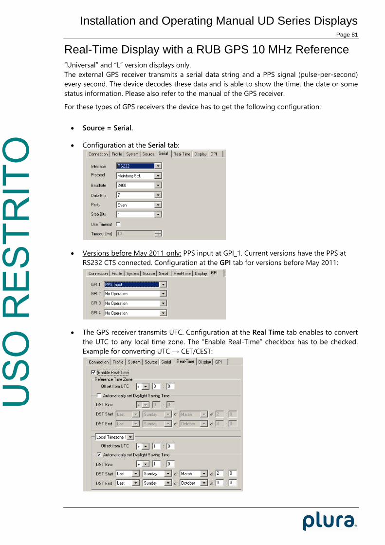
USO
RES
TRIT
O
Installation and Operating Manual UD Series Displays Page 81
Real-Time Display with a RUB GPS 10 MHz Reference
“Universal” and “L” version displays only.
The external GPS receiver transmits a serial data string and a PPS signal (pulse-per-second)
every second. The device decodes these data and is able to show the time, the date or some
status information. Please also refer to the manual of the GPS receiver.
For these types of GPS receivers the device has to get the following configuration:
Source = Serial.
Configuration at the Serial tab:
Versions before May 2011 only: PPS input at GPI_1. Current versions have the PPS at
RS232 CTS connected. Configuration at the GPI tab for versions before May 2011:
The GPS receiver transmits UTC. Configuration at the Real Time tab enables to convert
the UTC to any local time zone. The “Enable Real-Time“ checkbox has to be checked.
Example for converting UTC → CET/CEST:

USO
RES
TRIT
O
Installation and Operating Manual UD Series Displays Page 82
At the Display tab you can select the kind of data to be displayed:
Mode = Time Time of the GPS receiver, if the “Real-Time” mode has been
disabled. Local (converted) time, if the “Real-Time” mode has been
enabled.
Mode = Date Date of the GPS receiver, if the “Real-Time” mode has been
disabled. Local (converted) date, if the “Real-Time” mode has been
enabled.
Mode = Status Some information about the GPS receiver state – this may help on
fault finding. After power-on the GPS receiver needs some minutes
– dependent on receiving conditions – until valid data and a PPS
will be transmitted. As soon as the PPS is present the GPS receiver
transmits a reliable time.
Digit 1 Digit 2 Digit 3 Digit 4 Digit 5 Digit 6
Digit 1: P = PPS (pulse-per-second) is present.
– = PPS is not present.
Digit 2: d = Serial data are present.
– = Serial data are not present.
Digit 3: – = GPS receiver has not synchronized.
1 = GPS receiver has synchronized, but its position is still
not defined.
3 = GPS receiver has synchronized and determined its
position.
Digit 4: 1 ... 7 = day-of-week, 1 = Monday.
– = No valid day-of-week present.
Digit 5: U = GPS receiver transmits UTC.
S = GPS receiver transmits DST (daylight saving time).
– = GPS receiver transmits standard time (no DST).
Digit 6: A = Announcement of a DST switching.
L = Announcement of a leap second.
– = No announcement.
Connecting example (current version):
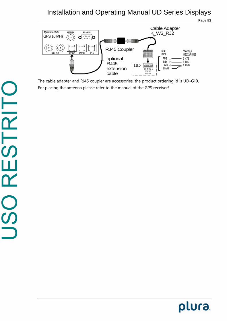
USO
RES
TRIT
O
Installation and Operating Manual UD Series Displays Page 83
RS232RS422
6 5 4 3 2 1RJ45 Coupler
Cable AdapterK_W6_RJ2
6 5 4 3 2 1
UD
1
10MHz OUT
Alpermann+Velte
GPI ABATT INREF OUT
ANTENNA PC / GPI B
GPS 10 MHz
1 . . . . . 8 1 . . . . . 8 1 . . . . . 8
optionalRJ45extensioncable
PPSTxDGNDShield
124
3 CTS5 RxD 1 GND
RJ45GPS
WAGO_6RS232/RS422
The cable adapter and RJ45 coupler are accessories, the product ordering id is UD-G10.
For placing the antenna please refer to the manual of the GPS receiver!

USO
RES
TRIT
O
Installation and Operating Manual UD Series Displays Page 84
Installation
Terminal Block Connections
The terminal block connection consists of the male connector fixed to the printed board and
the pluggable female connector. The terminal blocks are protected against mismating.
Conductors have to be inserted into the clamping units. A clamping unit consists of a spring
pressure connecting system which safely clamps the inserted conductor.
For installation please detach the pluggable part.
To introduce (or pull out) the conductor the clamping spring has to be opened. Use a small
screwdriver or a similar tool with a fine tip (≈ 2.5 x 0.4 mm / ≈ 0.098 x 0.016 in). Insert this tool
into the operating slot and push it to open the clamping spring. Then immediately push the
conductor in up to the stop (or pull it out). Please refer to picture 1.
Picture 1 Picture 2
Acceptable wires: Solid, stranded, fine-stranded or tip bonded stripped conductors.
Sizes: cross sections 0.08 – 0.5 mm2, AWG 28 – 20, Ø 0.33 – 0.96 mm.
Conductor material: copper or tin plated copper.
Stripping:
5 - 6 mm / 0.22 in
The female connector has marker strips. Additional coding is possible by removal of coding
finger(s). Using the strain relief plate is recommended to avoid stressing the conductor.
Please refer to picture 2.
CAUTION: These connectors can only be mated and unmated at voltages below
42 V and in the “no load” condition.

USO
RES
TRIT
O
Installation and Operating Manual UD Series Displays Page 85
LTC/MTD Loop Adapter
Available for “universal” or “L“ version displays.
The female connector of the LTC/MTD terminal block accepts wires with cross sections up to
0.5 mm2 only. This may not allow looping signals to other units. This adapter, which can be
plugged to the male LTC/MTD connector and attached to the housing by two screws, can
fulfil this application.
Clamping spring can be opened tool-less using
the black coloured lever.
Acceptable wires:
Solid, stranded, fine-stranded or tip bonded
stripped conductors.
Sizes: Cross sections 0.08 – 1.0 mm2,
AWG 28 – 18, Ø 0.33 – 1.02 mm.
Conductor material: Copper or tin plated copper.
Stripping:
6 - 8 mm / 0.27 in
This accessory is available on request.

USO
RES
TRIT
O
Installation and Operating Manual UD Series Displays Page 86
Strain Relief for Connecting Cables: Utilizing Cable Tie Holders
Two plastic cable tie holders are supplied accessories. Insert these snap-in elements through
the drilling holes (Ø = 4.8 mm) at the rear of the housing. Connection cables can be secured
in conjunction with cable ties.
Example:

USO
RES
TRIT
O
Installation and Operating Manual UD Series Displays Page 87
UD56-W: Wall, Tripod, and Table Mount Kit
UD56-W wall and table mount kit is an option for UD56 displays. Please order separately.
Parts List:
Qty Item
1 Mounting bracket
2 mm aluminium
2 Holding bracket
2 mm aluminium
4 Screws + washers
2 Knurled screws
4 Case feet
1a. Wall mount: Mount the mounting bracket at the wall. For a vertical wall and to keep it
detachable use the 1a and 1b drilled holes; otherwise use the 2a – 2c holes.
60 m
m
7 mm
431.4 mm
5.5 mm
10 mm
7 mm
40 m
m
331.4 mm
88.1
mm
491.4 mm
1a 1b
2c
2d
2a
2b
Stativgewinde / Screw Thread
Kabeldurchführungen 35 mm
180.0 mm
Cable Duct
1b. Tripod mount: The mounting bracket is fitted with a 3/8” UNC screw thread.

USO
RES
TRIT
O
Installation and Operating Manual UD Series Displays Page 88
1c. Table mount: Snap-in the case feet into the 2a – 2c drilled holes of the mounting
bracket. Press in the pin completely to lock. Simply release by pushing the pin from
other side.
2. Mount the holding brackets right and left of the device screwing them tight at the front
plate – see picture above.
3. Fasten the device at the mounting bracket using two knurled screws. Before tighten the
knurled screws adjust the inclination of the device.
114.5 mm106.0 mm 97.5 mm 89.0 mm
front plate of the display
109
mm
7 mm

USO
RES
TRIT
O
Installation and Operating Manual UD Series Displays Page 89
UD300: Wall Mounting
Square housing
All dimensions in millimetres.
Side view Rear view
30 30
60
324
320
73
160
87
166
324
32065 190 65
19664 64
17
1012
51.5
1215
69.5156 17
6
45
AC PowerIEC/EN 60320-1/C14
Screws or hooks with diameters up to 6 mm (0.236 in) can be used.
2012
Ø = 10
Ø = 6
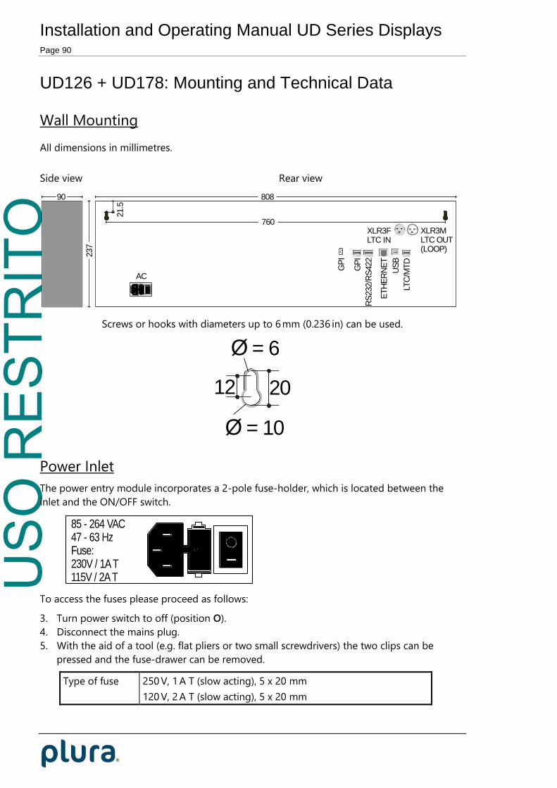
USO
RES
TRIT
O
Installation and Operating Manual UD Series Displays Page 90
UD126 + UD178: Mounting and Technical Data
Wall Mounting
All dimensions in millimetres.
Side view Rear view
237
90 808
760
21.5
12
3
21
3XLR3FLTC IN
XLR3MLTC OUT(LOOP)
AC
1 2 3 4 51 2 3 4 5 61 2 3 4 5
1
US
B
ET
HE
RN
ET
RS
232/R
S422
GP
I
GP
I
LTC
/MT
D
Screws or hooks with diameters up to 6 mm (0.236 in) can be used.
2012
Ø = 10
Ø = 6
Power Inlet
The power entry module incorporates a 2-pole fuse-holder, which is located between the
inlet and the ON/OFF switch.
Fuse:230V / 1A T115V / 2A T
85 - 264 VAC47 - 63 Hz
To access the fuses please proceed as follows:
3. Turn power switch to off (position O).
4. Disconnect the mains plug.
5. With the aid of a tool (e.g. flat pliers or two small screwdrivers) the two clips can be
pressed and the fuse-drawer can be removed.
Type of fuse 250 V, 1 A T (slow acting), 5 x 20 mm
120 V, 2 A T (slow acting), 5 x 20 mm

USO
RES
TRIT
O
Installation and Operating Manual UD Series Displays Page 91
Warning: To avoid fire hazard, use only type of fuse as
specified above.

USO
RES
TRIT
O
Installation and Operating Manual UD Series Displays Page 92
UD25TT: Space Saving Housing
This space saving housing offers three M3 threaded holes at each side.
All dimensions in millimetres.
View from above:
209.1 1.31.3
View from aside:
2.5 44.5 3.0
13
15
13
12.0 22.0
3 x M3
Attention: Two screws at the right side should not be screwed in more than 2.5 mm!
Alpermann+Velte
2.5 mm