Embed Size (px)
Citation preview
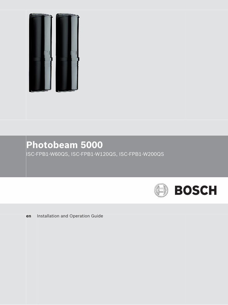
Photobeam 5000ISC-FPB1-W60QS, ISC-FPB1-W120QS, ISC-FPB1-W200QS
en Installation and Operation Guide


Table of contents
1 Introduction 41.1 About documentation 41.2 Bosch Security Systems, Inc 4
2 System overview 52.1 Features 52.2 Photobeam overview 62.3 Console overview 72.4 Transmitter/receiver dimensions 8
3 Installation 93.1 Beam spread 93.2 Pole mount installation 103.3 Wall mount installation 12
4 Wiring 134.1 Terminal strip overview 134.2 Wiring distance 144.3 Wiring routes 14
5 Special features 165.1 Level LED 165.2 EDC (Environmental Discrimination Circuit) 165.3 Beam interruption time 175.4 Beam power control 17
6 Setup 187 Optical alignment 207.1 Level LED - alignment of the Upper Beam 207.2 Level LED - alignment of the Lower Beam 207.3 Volt meter alignment 21
8 Operational check 229 Troubleshooting 239.1 Additional information 23
10 Certifications 2411 Specifications 25
Photobeam 5000 Table of Contents | en 3
Bosch Security Systems, Inc. Installation and Operation Guide 2016.02 | 03 | F.01U.305.910

IntroductionThis document contains information that a trained installer needs to install the Photobeam5000 quad-beam photoelectric detector contained inside the packaging.
About documentationCopyrightThis document is the intellectual property of Bosch Security Systems, Inc. and is protected bycopyright. All rights reserved.
TrademarksAll hardware and software product names used in this document are likely to be registeredtrademarks and must be treated accordingly.
Bosch Security Systems, IncUse the serial number located on the product label and refer to the Bosch Security Systems,Inc. website at http://www.boschsecurity.com/datecodes/.Manufacturing date information is contained in digit no 1 – 3: DDD.
1
1.1
1.2
4 en | Introduction Photobeam 5000
2016.02 | 03 | F.01U.305.910 Installation and Operation Guide Bosch Security Systems, Inc.

System overviewThe ISC-FPB1-W60QS, ISC-FPB1-W120QS and ISC-FPB1-W200QS are quad-beamphotoelectric detectors designed for indoor and outdoor applications. Consisting of aseparate transmitter and receiver, an alarm is activated when a person passes through all fourbeams. Combination of features and adjustable parameters allow for better catchperformance, lower false alarm rates and reduced effects of environmental disturbances.
FeaturesFor stable operation, the detectors are equipped with the following feautres:
100% Sensitivity AllowanceMaintains stable operation even if 99% of beam energy is cut, for example by rain, fog, frost,and so on.
Quad Beam DetectionFewer false alarms caused by birds and other small animals because all four beams must beblocked simultaneously to cause an alarm.
Beam Power ControlSelect the appropriate beam intensity relative to the detection range to minimize reflection onnearby walls and cross-talk with other detectors.
Beam Interruption Time ControlUse to change the beam interruption time to best fit the application.
2
2.1
Photobeam 5000 System overview | en 5
Bosch Security Systems, Inc. Installation and Operation Guide 2016.02 | 03 | F.01U.305.910

Photobeam overview
2
1
1
4
5
67
8
9
10
11
10
9
7
83
13
12
Figure 2.1: Photobeam components overview
Callout ー Description Callout ー Description
1 ー Mounting holes 8 ー Optical alignment
2 ー Mounting plate 9 ー Vertical adjustment
3 ー Device securing screws 10 ー Horizontal adjustment
4 ー Wire entry 11 ー Console
5 ー Wiring terminals 12 ー Cover
6 ー Detector 13 ー Cover securing screws
7 ー Optical module
2.2
6 en | System overview Photobeam 5000
2016.02 | 03 | F.01U.305.910 Installation and Operation Guide Bosch Security Systems, Inc.

Console overview
2
3
6
4
8
7
1 5
Figure 2.2: Console components overview
Callout ー Description Callout ー Description
1 ー Transmitter console 5 ー Receiver console
2 ー Power Indicator 6 ー Status Indicators
3 ー Function switches 7 ー Sensitivity control
4 ー Beam Power Control 8 ー Alignment check terminals
2.3
Photobeam 5000 System overview | en 7
Bosch Security Systems, Inc. Installation and Operation Guide 2016.02 | 03 | F.01U.305.910

Transmitter/receiver dimensions
1
103 mm (4.0 in)
19.3 mm
(0.75 in)
398 m
m (
15.6
6 in)
244 m
m (
9.6
0 in)
96 mm (3.77 in)
77.1
mm
(3.0
3 in)
337.7
mm
(13.2
9 in)
56 mm
(2.20 in)
220 m
m (
8.6
6 in)
39 m
m
(1.5
in)
39.7
mm
(1.5
6 in)
2
3
4
Figure 2.3: Transmitter/receiver dimensions
Callout ﹘ Description Callout ﹘ Description
1 ー Knockout wire entrance 3 ー Center of the Upper Beam
2 ー Center of the Lower Beam 4 ー Wire entrance
2.4
8 en | System overview Photobeam 5000
2016.02 | 03 | F.01U.305.910 Installation and Operation Guide Bosch Security Systems, Inc.
InstallationPrior to installing the devices, please review the installation considerations below:– Install in an area that is clear of objects– Install the transmitter/receiver within the maximum protection range of the model– Do not install:
– Receivers into intense sources of light (for example, rising and setting sun)– On movable surfaces subject to vibrations– Detectors where immersion to water, corrosive liquids, or exposure to high levels of
dust can occur– Detectors in close proximity to strong electromagnetic noises
– Do not use detectors with other photobeam detectors or receivers– Do not stack detectors– Do not disassemble or modify this detector– Do not install while the power is on– Avoid extreme temperature and humidity ranges as defined in the products specifications– Avoid installing detectors near magnets and/or magnetized materials– Avoid beam interference between other units when multiple units are installed.
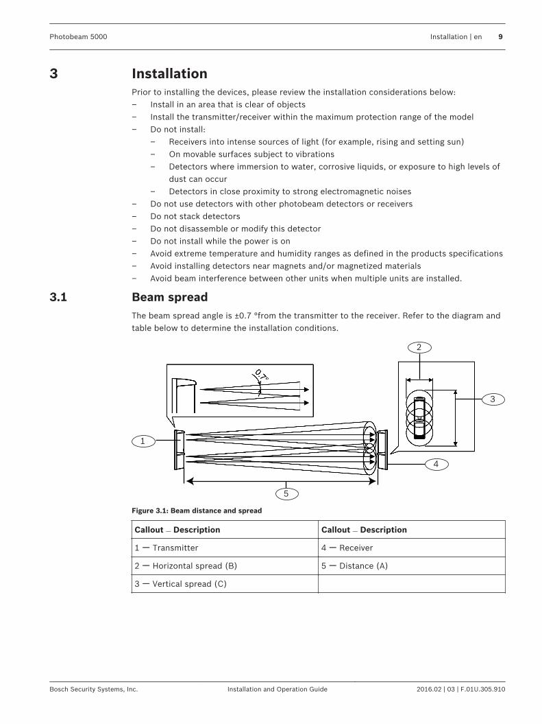
Beam spreadThe beam spread angle is ±0.7 °from the transmitter to the receiver. Refer to the diagram andtable below to determine the installation conditions.
1
5
4
3
2
Figure 3.1: Beam distance and spread
Callout ﹘ Description Callout ﹘ Description
1 ー Transmitter 4 ー Receiver
2 ー Horizontal spread (B) 5 ー Distance (A)
3 ー Vertical spread (C)
3
3.1
Photobeam 5000 Installation | en 9
Bosch Security Systems, Inc. Installation and Operation Guide 2016.02 | 03 | F.01U.305.910
Distance, horizontal and vertical spread values: (A) / (B) / (C)
Metric Imperial unit
20 m / 0.5 m / 0.8 m 65 ft / 1.6 ft / 2.6 ft
40 m / 1.0 m /1.3 m 13.1 ft / 3.2 ft / 4.2 ft
60 m / 1.5m / 1.8 m 196 ft / 4.9 ft / 5.9 ft
80 m / 2.0 m / 2.2 m 262 ft / 6.5 ft / 7.2 ft
100 m / 2.5 m / 2.7 m 328 ft / 8.2 ft / 8.8 ft
120 m / 3.0 m / 3.2 m 393 ft / 9.8 ft / 10.4 ft
140 m / 3.5 m / 3.7 m 459 ft / 11.4 ft / 12.1 ft
160 m / 4.0 m / 4.2 m 524 ft / 13.1 ft / 13.7 ft
180 m / 4.5 m / 4.7 m 590 ft / 14.7 ft / 15.4 ft
200 m / 5.0 m / 5.2 m 656 ft / 16.4 ft / 17.0 ft
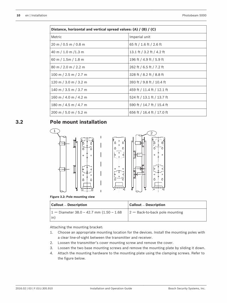
Pole mount installation
12
Figure 3.2: Pole mounting view
Callout ﹘ Description Callout ﹘ Description
1 ー Diameter 38.0 – 42.7 mm (1.50 – 1.68in)
2 ー Back-to-back pole mounting
Attaching the mounting bracket:1. Choose an appropriate mounting location for the devices. Install the mounting poles with
a clear line-of-sight between the transmitter and receiver.2. Loosen the transmitter’s cover mounting screw and remove the cover.3. Loosen the two base mounting screws and remove the mounting plate by sliding it down.4. Attach the mounting hardware to the mounting plate using the clamping screws. Refer to
the figure below.
3.2
10 en | Installation Photobeam 5000
2016.02 | 03 | F.01U.305.910 Installation and Operation Guide Bosch Security Systems, Inc.

1
3
2
Figure 3.3: Attaching the mounting bracket
Callout ﹘ Description
1 ー Mounting hardware
2 ー Mounting plate
3 ー Clamping screws (short)
Attaching the mounting plate:1. Attach the mounting plate to the poles using the U-clamps.2. Use the U-clamps and clamping screws to attach the mounting plate firmly to the poles.
4
2
3
1
Figure 3.4: Attaching the U-clamp
Callout ﹘ Description
1 ー U-clamp
2 ー Mounting pole
3 ー Mounting plate
4 ー Clamping screws (long)
Wire routing:1. Route the wire through the wire entry location of the mounting plate, leave enough wire
to reach the terminal strip.2. Route the wire through the transmitter’s wire entry.3. Slide the transmitter onto the mounting plate, and secure using the included screws.4. Repeat this procedure for the receiver, verify line-of-sight with the transmitter.5. Wire to the terminal strips. Refer to Wiring, page 13 for wiring procedures.
Photobeam 5000 Installation | en 11
Bosch Security Systems, Inc. Installation and Operation Guide 2016.02 | 03 | F.01U.305.910
!
Caution!
Ensure that the pole mount installation is secure and stable. Failure to do so may result in
personal injury, or damage the device.
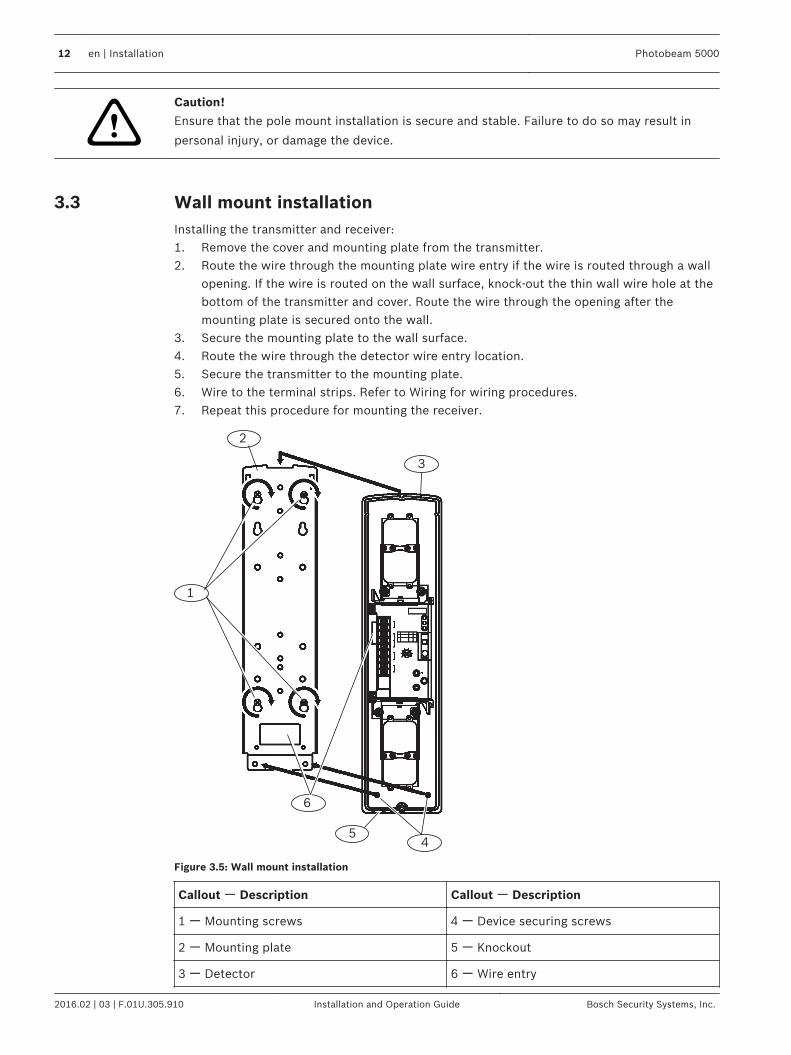
Wall mount installationInstalling the transmitter and receiver:1. Remove the cover and mounting plate from the transmitter.2. Route the wire through the mounting plate wire entry if the wire is routed through a wall
opening. If the wire is routed on the wall surface, knock-out the thin wall wire hole at thebottom of the transmitter and cover. Route the wire through the opening after themounting plate is secured onto the wall.
3. Secure the mounting plate to the wall surface.4. Route the wire through the detector wire entry location.5. Secure the transmitter to the mounting plate.6. Wire to the terminal strips. Refer to Wiring for wiring procedures.7. Repeat this procedure for mounting the receiver.
1
4
2
6
5
3
Figure 3.5: Wall mount installation
Callout ー Description Callout ー Description
1 ー Mounting screws 4 ー Device securing screws
2 ー Mounting plate 5 ー Knockout
3 ー Detector 6 ー Wire entry
3.3
12 en | Installation Photobeam 5000
2016.02 | 03 | F.01U.305.910 Installation and Operation Guide Bosch Security Systems, Inc.

WiringRefer to Terminal strip below for transmitter/receiver terminal locations. Use ductpipes for outdoor wiring. Do not use aerial wiring.
!
Caution!
Only apply power after all electrical connections are completed and inspected.
Notice!
Tamper and EDC terminals should be connected to a 24-hour supervisory loop
Notice!
Power is to be provided by a UL Listed burglar alarm power supply or burglar alarm control
panel. In case of power failure, the power supply or control unit shall have a minimum of 4
hours of standby power.
Notice!
All wiring is to be in accordance with the National Electric Code, ANSI/NFPA 70
Notice!
This system should be tested at least once a week to ensure proper function.
Terminal strip overview
1 2
343564
Figure 4.1: Terminal strip component overview
Callout ﹘ Description Callout ﹘ Description
1 ー Receiver 4 ー Tamper
2 ー Transmitter 5 ー Alarm output
3 ー Power (non-polarized) 6 ー EDC output
4
4.1
Photobeam 5000 Wiring | en 13
Bosch Security Systems, Inc. Installation and Operation Guide 2016.02 | 03 | F.01U.305.910
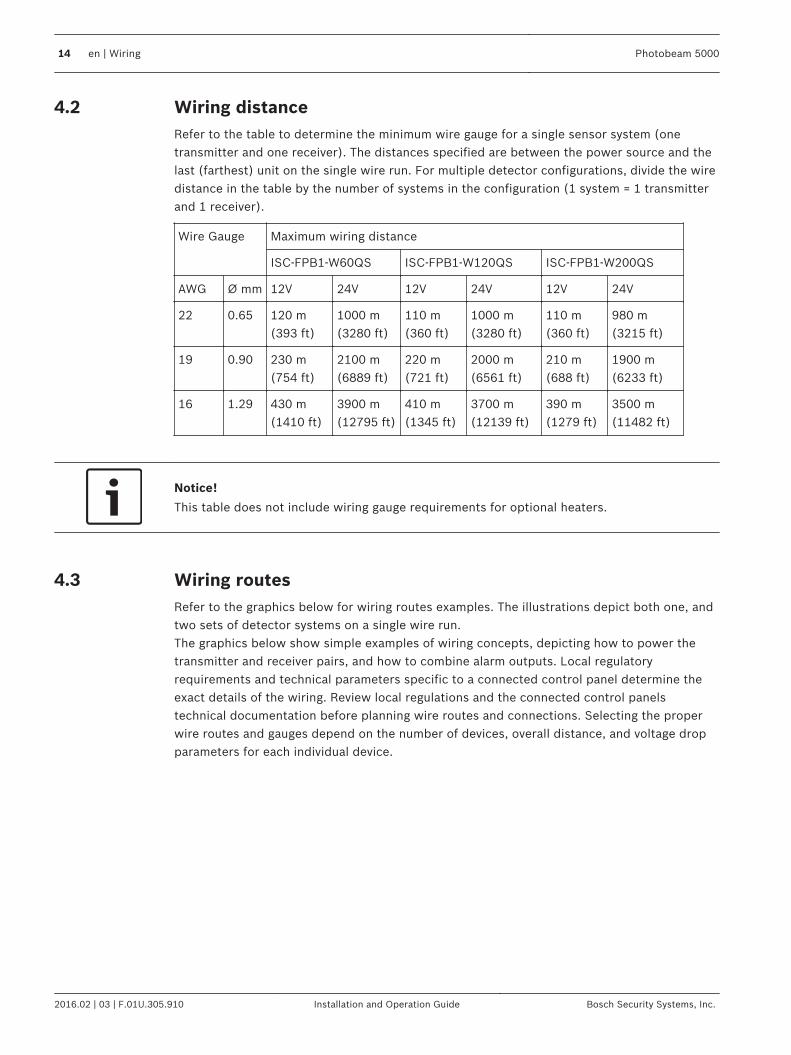
Wiring distanceRefer to the table to determine the minimum wire gauge for a single sensor system (onetransmitter and one receiver). The distances specified are between the power source and thelast (farthest) unit on the single wire run. For multiple detector configurations, divide the wiredistance in the table by the number of systems in the configuration (1 system = 1 transmitterand 1 receiver).
Wire Gauge Maximum wiring distance
ISC-FPB1-W60QS ISC-FPB1-W120QS ISC-FPB1-W200QS
AWG Ø mm 12V 24V 12V 24V 12V 24V
22 0.65 120 m(393 ft)
1000 m(3280 ft)
110 m(360 ft)
1000 m(3280 ft)
110 m(360 ft)
980 m(3215 ft)
19 0.90 230 m(754 ft)
2100 m(6889 ft)
220 m(721 ft)
2000 m(6561 ft)
210 m(688 ft)
1900 m(6233 ft)
16 1.29 430 m(1410 ft)
3900 m(12795 ft)
410 m(1345 ft)
3700 m(12139 ft)
390 m(1279 ft)
3500 m(11482 ft)
Notice!
This table does not include wiring gauge requirements for optional heaters.
Wiring routesRefer to the graphics below for wiring routes examples. The illustrations depict both one, andtwo sets of detector systems on a single wire run.The graphics below show simple examples of wiring concepts, depicting how to power thetransmitter and receiver pairs, and how to combine alarm outputs. Local regulatoryrequirements and technical parameters specific to a connected control panel determine theexact details of the wiring. Review local regulations and the connected control panelstechnical documentation before planning wire routes and connections. Selecting the properwire routes and gauges depend on the number of devices, overall distance, and voltage dropparameters for each individual device.
4.2
4.3
14 en | Wiring Photobeam 5000
2016.02 | 03 | F.01U.305.910 Installation and Operation Guide Bosch Security Systems, Inc.

4
1
5
23
4
Figure 4.2: Wiring for one set on the run
Callout ﹘ Description Callout ﹘ Description
1 ー Power output 4 ー Control panel
2 ー Transmitter 5 ー Alarm input. The COM and NC terminalson the unit are the outputs, they connect to acontrol panel input.
3 ー Receiver
1
5
4
3 2
3 2
Figure 4.3: Wiring for two sets on a single run
Callout ﹘ Description Callout ﹘ Description
1 ー Power output 4 ー Control panel
2 ー Transmitter 5 ー Alarm input. The COM and NC terminalson the unit are the outputs, they connect to acontrol panel input.
3 ー Receiver
Notice!
The BH12T heater is an optional device. Refer to the BH12T installation instructions (P/N: W.
97.2195) for more information.
Photobeam 5000 Wiring | en 15
Bosch Security Systems, Inc. Installation and Operation Guide 2016.02 | 03 | F.01U.305.910

Special featuresRefer to the following for sensitivity adjustments.
Level LEDThe Level LED shows the beams energy level received during alignment. As more beam energyis received, the illumination time shortens as follows: ON => OFF once => OFF twice => OFFthree times => Flashing => ON three times => ON twice => ON once => OFF.When the LED turns off, the alignment is complete.Refer to Console overview, page 7 for Status Indicator locations (callout #6).
EDC (Environmental Discrimination Circuit)The EDC generates a signal when the beam power level is significantly reduced due toenvironmental conditions such as fog or rain. Two Bypass switch features are used at thereceiver, Bypass Switch Off, and Bypass Switch On.The inability to operate for more than 3 seconds due to environmental conditions is defined asa “Poor Environmental Condition.”
Switch Condition Description
Off When poorenvironmental conditionspresent:
The EDC LED turns on and the EDC output activates.Alarm signal is generated upon further loss of the beamenergy.
When either opticalmodule is blocked for 3or more seconds:
The EDC LED turns on and the EDC output activates. Noalarm is generated.
When both opticalmodules are blocked for3 or more seconds:
The alarm LED turns on and an alarm signal is generated.EDC LED turns on and EDC output activates.
On When poorenvironmental conditionspresent:
The EDC LED turns on and the EDC output activates.Alarm LED turns on after further loss of beam energy butdoes not generate an alarm signal.
When either opticalmodule is blocked for 3or more seconds:
The EDC LED turns on and provides a EDC signal. AlarmLED turns on without generating an alarm signal ifanother optical module is blocked.
When both opticalmodules are blocked for3 or more seconds:
The alarm LED turns on and alarm signal is generated.EDC LED does not turn on and does not activate the EDCoutput. It is recommended to connect the EDC output toa trouble input point at the control panel. It isrecommended to check the system any time the EDCrelay has been activated.
Notice!
Connect the EDC to an input circuit and check the system any time the EDC relay is activated.
5
5.1
5.2
16 en | Special features Photobeam 5000
2016.02 | 03 | F.01U.305.910 Installation and Operation Guide Bosch Security Systems, Inc.
Notice!
The EDC feature was not investigated by Underwriters Laboratories (UL).
Beam interruption timeThe beam interruption time defines the amount of time an intruder must spend in the beampath before an alarm is generated. For instance, if the interruption time is set at 100 ms, thedetector only generates an alarm if the beams are blocked for more than 100 ms.
Notice!
For UL applications, do not set the interrupt time above 75 ms.
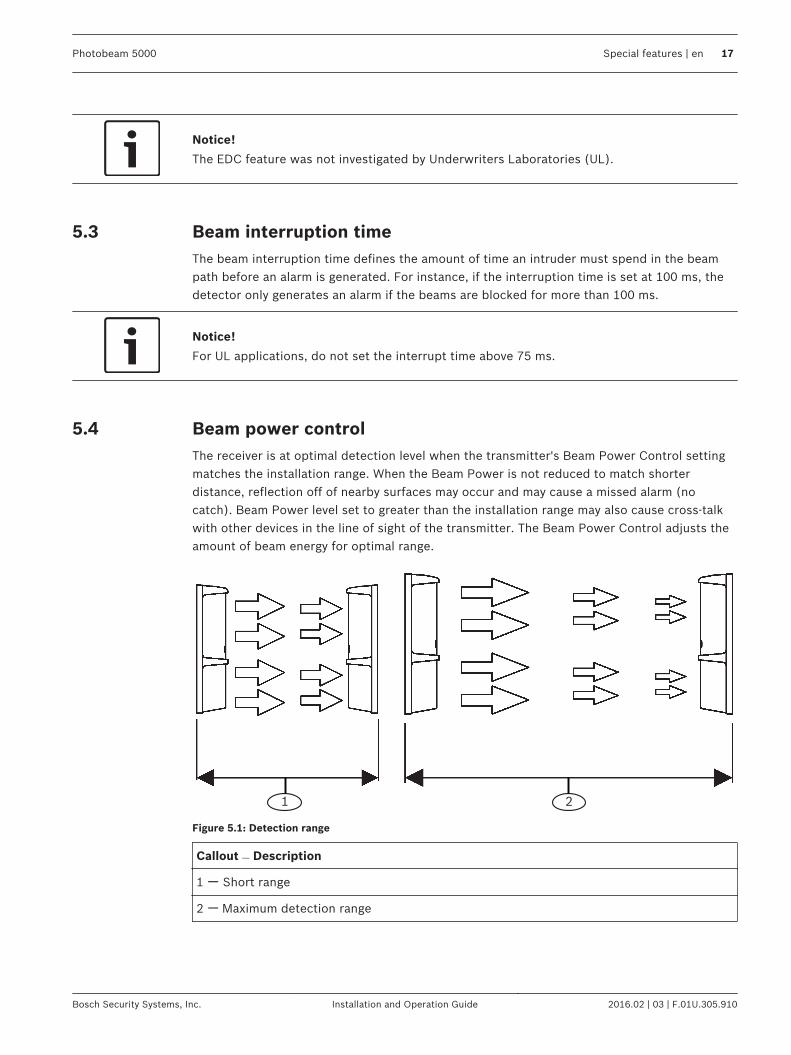
Beam power controlThe receiver is at optimal detection level when the transmitter's Beam Power Control settingmatches the installation range. When the Beam Power is not reduced to match shorterdistance, reflection off of nearby surfaces may occur and may cause a missed alarm (nocatch). Beam Power level set to greater than the installation range may also cause cross-talkwith other devices in the line of sight of the transmitter. The Beam Power Control adjusts theamount of beam energy for optimal range.
1 2
Figure 5.1: Detection range
Callout ﹘ Description
1 ー Short range
2 ー Maximum detection range
5.3
5.4
Photobeam 5000 Special features | en 17
Bosch Security Systems, Inc. Installation and Operation Guide 2016.02 | 03 | F.01U.305.910

SetupTurn the Bypass switch on to activate the bypass feature.
1
3
2
Figure 6.1: Receiver Bypass switch
Callout ー Description
1 ー Receiver
2 ー Bypass switch (switch 1)
3 ー Sensitivity control
Interruption timeTurn the sensitivity control on the receiver clockwise to reduce sensitivity andcounterclockwise to increase sensitivity.
1 2 3 4 5
Figure 6.2: Interruption time settings
Callout ー Description Callout ー Description
1 ー 40 ms running 4 ー 300 ms slow walking
2 ー 75 ms jogging 5 ー 400 – 500 ms slow walking
3 ー 150 – 200 ms walking
Beam power controlTurn the Beam Power Control on the transmitter clockwise to increase beam power. Turncounter-clockwise to decrease beam power. Refer to table below. For UL applications, theinterruption time cannot exceed 75 ms.
6
18 en | Setup Photobeam 5000
2016.02 | 03 | F.01U.305.910 Installation and Operation Guide Bosch Security Systems, Inc.
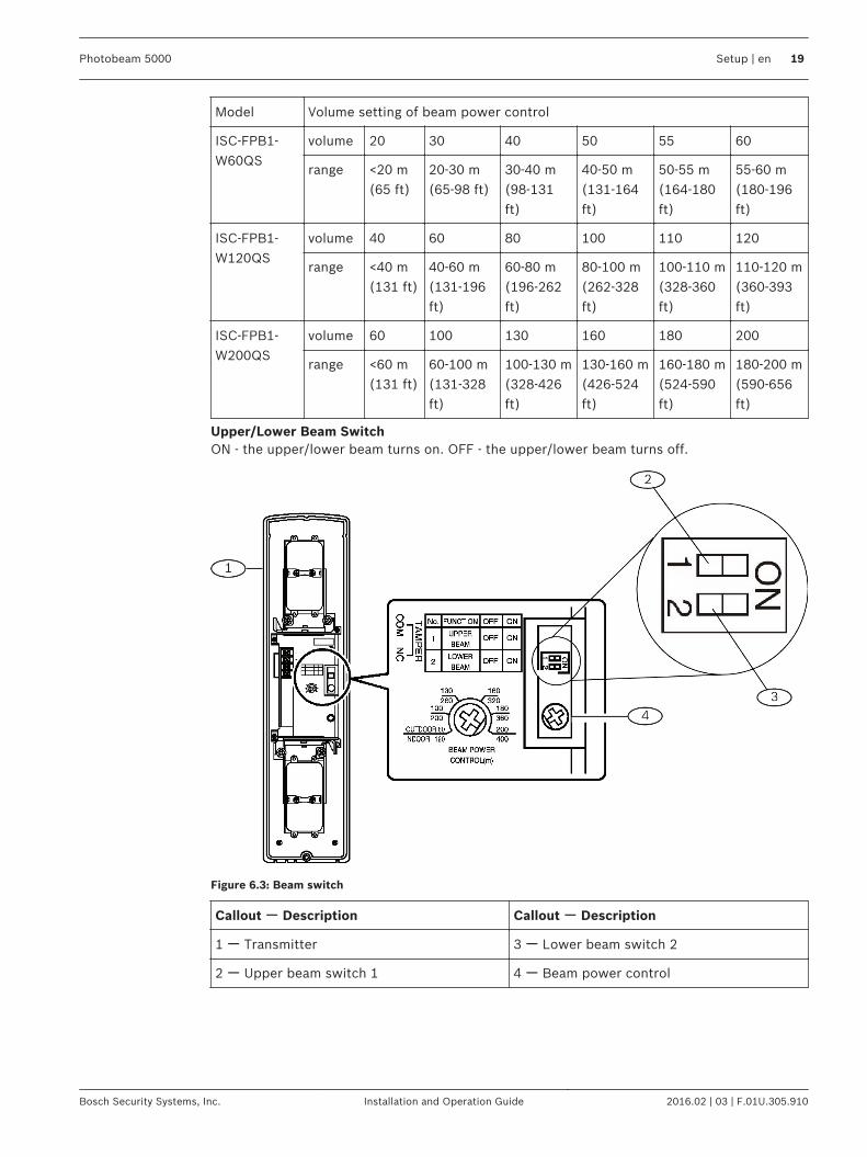
Model Volume setting of beam power control
ISC-FPB1-W60QS
volume 20 30 40 50 55 60
range <20 m(65 ft)
20-30 m(65-98 ft)
30-40 m(98-131ft)
40-50 m(131-164ft)
50-55 m(164-180ft)
55-60 m(180-196ft)
ISC-FPB1-W120QS
volume 40 60 80 100 110 120
range <40 m(131 ft)
40-60 m(131-196ft)
60-80 m(196-262ft)
80-100 m(262-328ft)
100-110 m(328-360ft)
110-120 m(360-393ft)
ISC-FPB1-W200QS
volume 60 100 130 160 180 200
range <60 m(131 ft)
60-100 m(131-328ft)
100-130 m(328-426ft)
130-160 m(426-524ft)
160-180 m(524-590ft)
180-200 m(590-656ft)
Upper/Lower Beam SwitchON - the upper/lower beam turns on. OFF - the upper/lower beam turns off.
Figure 6.3: Beam switch
Callout ー Description Callout ー Description
1 ー Transmitter 3 ー Lower beam switch 2
2 ー Upper beam switch 1 4 ー Beam power control
Photobeam 5000 Setup | en 19
Bosch Security Systems, Inc. Installation and Operation Guide 2016.02 | 03 | F.01U.305.910

Optical alignmentPerform the following to align the detector.
Level LED - alignment of the Upper BeamPerform the following to align the upper beam.Aligning of the upper bean:1. Turn on the transmitter Function switch 1 (Upper Beam). The monitor LED flashes (5
times/sec).2. Turn on the receiver Function switch 2 (Level Check) of the receiver.3. Look into the scope at the center of the lens from a 10-15 cm (4-5 in) distance, adjust the
horizontal direction by rotating the turntable and the horizontal adjustment screw. Adjustthe vertical direction by rotating the vertical adjustment screw. Adjust until you locate theother part of the sensor in the center of the scope view.
4. Check the level LED of the receiver. Perform fine adjustments and repeat procedure untilLED turns off. Refer to Volt meter alignment, page 21.
1
23
4
5
Figure 7.1: Optical alignment
Callout ー Description Callout ー Description
1 ー Turntable 4 ー Scope view finder
2 ー Verticle adjustment screw 5 ー On/Off switch
3 ー Horizontal adjustment screw 6
Notice!
Turn on Function switches 1 and 2 of the transmitter after finishing the alignment to verify the
monitor LEDs light up once every 3 seconds.
Level LED - alignment of the Lower BeamPerform the following to align the lower beam.Aligning of the lower beam:1. Turn on the transmitter Function switch 2 (Lower Beam).
7
7.1
7.2
20 en | Optical alignment Photobeam 5000
2016.02 | 03 | F.01U.305.910 Installation and Operation Guide Bosch Security Systems, Inc.

2. Turn on the receiver Function switch 2 (Level Check). Follow steps 3 and 4 as listed inthe Level LED - alignment of the Upper Beam, page 20. If the LED turns off, alignment iscomplete.
1
Figure 7.2: LED alignment
Callout ー Description
1 ー Receiver LED console
Volt meter alignmentInsert the volt meter leads into the alignment check terminals of the receiver to check voltage.If the value is 3.0 V or higher, the adjustment is completed. If less than 3.0 V, adjust thereceiver and transmitter until 3.0 V is obtained.
Notice!
In an ideal environment, the voltage is 3.0 VDC or above.
1
Figure 7.3: Volt meter alignment
Callout ﹘ Description
1 ー Alignment check terminals
Notice!
Turn on Function switches 1 and 2 of the transmitter after finishing the alignment to verify the
monitor LEDs light up once every 3 seconds.
7.3
Photobeam 5000 Optical alignment | en 21
Bosch Security Systems, Inc. Installation and Operation Guide 2016.02 | 03 | F.01U.305.910

Operational checkPerform the following to test the overall operation of the system.
Walk testTesting the alarm signal:1. Walk along the beam path near the transmitter and receiver in a pattern crossing the
beam signal in three different areas as depicted in the illustration below (callout’s 2, 4and 5 – Walk test crossing location), and check the alarm LEDs. Refer to the Walk testillustration below. The alarm LED turns on each time you cross the beam path. Make surethe control panel receives an alarm signal.
2. If the alarm LED does not turn on, the beam interruption time may be set too low, orother beams are reflected into the receiver.
1
5
6
42
3
Figure 8.1: Walk test pattern
Callout ﹘ Description Callout ﹘ Description
1 ー Transmitter 4 ー Walk test crossing location 2
2 ー Walk test crossing location 1 5 ー Walk test crossing location 3
3 ー Beam path 6 ー Receiver
EDC testTesting the EDC signal:1. Block only the upper optical module of the receiver for 3 seconds. Make sure the EDC
LED on the receiver turns on.2. When the EDC LED is ON, block the lower optical module, and confirm the alarm LED on
the receiver turns on.3. Block only the lower optical module of receiver for 3 seconds. Make sure the EDC LED on
the receiver turns on. Make sure the control panel receives EDC signal from the receiver.Verify bypass feature settings. Refer to the EDC function description in EDC(Environmental Discrimination Circuit), page 16.
Tamper testTesting the tamper detect circuit:1. Place the cover on the detector. Verify the tamper input of the control panel indicates
normal status condition.2. Remove the cover from the detector. Verify the tamper input of the control panel detects
the status change and indicates the faulted (active) condition.
8
22 en | Operational check Photobeam 5000
2016.02 | 03 | F.01U.305.910 Installation and Operation Guide Bosch Security Systems, Inc.
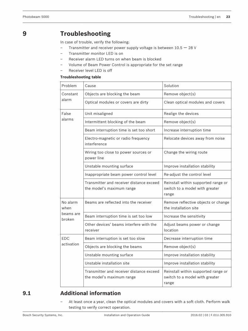
TroubleshootingIn case of trouble, verify the following:– Transmitter and receiver power supply voltage is between 10.5 ー 28 V– Transmitter monitor LED is on– Receiver alarm LED turns on when beam is blocked– Volume of Beam Power Control is appropriate for the set range– Receiver level LED is off
Troubleshooting table
Problem Cause Solution
Constantalarm
Objects are blocking the beam Remove object(s)
Optical modules or covers are dirty Clean optical modules and covers
Falsealarms
Unit misaligned Realign the devices
Intermittent blocking of the beam Remove object(s)
Beam interruption time is set too short Increase interruption time
Electro-magnetic or radio frequencyinterference
Relocate devices away from noise
Wiring too close to power sources orpower line
Change the wiring route
Unstable mounting surface Improve installation stability
Inappropriate beam power control level Re-adjust the control level
Transmitter and receiver distance exceedthe model’s maximum range
Reinstall within supported range orswitch to a model with greaterrange
No alarmwhenbeams arebroken
Beams are reflected into the receiver Remove reflective objects or changethe installation site
Beam interruption time is set too low Increase the sensitivity
Other devices’ beams interfere with thereceiver
Adjust beams power or changelocation
EDCactivation
Beam interruption is set too slow Decrease interruption time
Objects are blocking the beams Remove object(s)
Unstable mounting surface Improve installation stability
Unstable installation site Improve installation stability
Transmitter and receiver distance exceedthe model’s maximum range
Reinstall within supported range orswitch to a model with greaterrange
Additional information– At least once a year, clean the optical modules and covers with a soft cloth. Perform walk
testing to verify correct operation.
9
9.1
Photobeam 5000 Troubleshooting | en 23
Bosch Security Systems, Inc. Installation and Operation Guide 2016.02 | 03 | F.01U.305.910
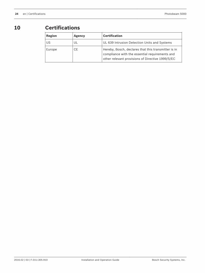
CertificationsRegion Agency Certification
US UL UL 639 Intrusion Detection Units and Systems
Europe CE Hereby, Bosch, declares that this transmitter is incompliance with the essential requirements andother relevant provisions of Directive 1999/5/EC
10
24 en | Certifications Photobeam 5000
2016.02 | 03 | F.01U.305.910 Installation and Operation Guide Bosch Security Systems, Inc.
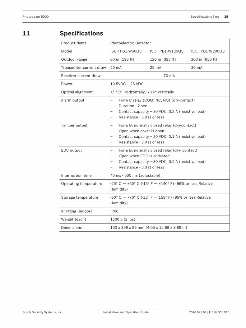
SpecificationsProduct Name Photoelectric Detector
Model ISC-FPB1-W60QS ISC-FPB1-W120QS ISC-FPB1-W200QS
Outdoor range 60 m (196 ft) 120 m (393 ft) 200 m (656 ft)
Transmitter current draw 20 mA 25 mA 30 mA
Receiver current draw 70 mA
Power 10.5VDC – 28 VDC
Optical alignment +/- 90° Horizontally,+/-10° vertically
Alarm output – Form C relay (COM, NC, NO) (dry-contact)– Duration - 2 sec– Contact capacity – 30 VDC, 0.2 A (resistive load)– Resistance - 3.0 Ω or less
Tamper output – Form B, normally closed relay (dry-contact)– Open when cover is open– Contact capacity – 30 VDC, 0.1 A (resistive load)– Resistance - 3.0 Ω or less
EDC output – Form B, normally closed relay (dry- contact)– Open when EDC is activated– Contact capacity – 30 VDC, 0.2 A (resistive load)– Resistance - 3.0 Ω or less
Interruption time 40 ms - 500 ms (adjustable)
Operating temperature -25° C ー +60° C (-13° F ー +140° F) (96% or less RelativeHumidity)
Storage temperature -30° C ー +70° C (-22° F ー 158° F) (95% or less RelativeHumidity)
IP rating (indoor) IP66
Weight (each) 1200 g (2 lbs)
Dimensions 103 x 398 x 99 mm (4.05 x 15.66 x 3.89 in)
11
Photobeam 5000 Specifications | en 25
Bosch Security Systems, Inc. Installation and Operation Guide 2016.02 | 03 | F.01U.305.910


Bosch Security Systems, Inc.130 Perinton ParkwayFairport, NY 14450USAwww.boschsecurity.com© Bosch Security Systems, Inc., 2016
Bosch Sicherheitssysteme GmbHRobert-Bosch-Ring 585630 GrasbrunnGermanywww.boschsecurity.com