Embed Size (px)
Citation preview
Installation and Operation Handbook Contents
2216e, 2208e & 2204e FM Alarm Units. Applies to sw version A4.51. Part No. HA027696, issue 2.0
MODELS 2216e, 2208e and 2204e FM TEMPERATURE ALARM UNITS
INSTALLATION AND OPERATION HANDBOOK
Contents Page
WARNING NOTICE ii
Chapter 1 INSTALLATION 1-1
Chapter 2 OPERATION 2-1
Chapter 3 ACCESS LEVELS 3-1
Chapter 4 CONFIGURATION 4-1
Appendix A ORDERING CODE A-1
Appendix B SAFETY AND EMC INFORMATION B-1
This product is covered by US Patent 5,484,206
Contents Installation and Operation Handbook
ii 2216e, 2208e & 2204e FM Alarm Units. Applies to sw version A4.51 Part No. HA027696, issue 2.0
WARNING NOTICE
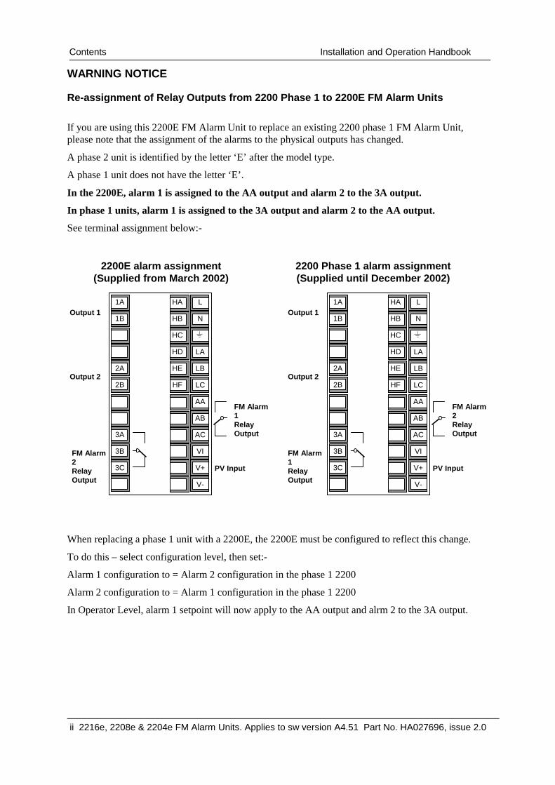
Re-assignment of Relay Outputs from 2200 Phase 1 to 2200E FM Alarm Units
If you are using this 2200E FM Alarm Unit to replace an existing 2200 phase 1 FM Alarm Unit, please note that the assignment of the alarms to the physical outputs has changed.
A phase 2 unit is identified by the letter ‘E’ after the model type.
A phase 1 unit does not have the letter ‘E’.
In the 2200E, alarm 1 is assigned to the AA output and alarm 2 to the 3A output.
In phase 1 units, alarm 1 is assigned to the 3A output and alarm 2 to the AA output.
See terminal assignment below:-
When replacing a phase 1 unit with a 2200E, the 2200E must be configured to reflect this change.
To do this – select configuration level, then set:-
Alarm 1 configuration to = Alarm 2 configuration in the phase 1 2200
Alarm 2 configuration to = Alarm 1 configuration in the phase 1 2200
In Operator Level, alarm 1 setpoint will now apply to the AA output and alrm 2 to the 3A output.
Output 1
PV Input
Output 2
1A
1B
2A
2B
3A
3B
3C
L
N
LA
LB
LC
AA
AB
AC
VI
V+
V-
HA
HB
HC
HD
HE
HF
FM Alarm 1 Relay Output
FM Alarm 2 Relay Output
2200E alarm assignment (Supplied from March 2002)
Output 1
PV Input
Output 2
1A
1B
2A
2B
3A
3B
3C
L
N
LA
LB
LC
AA
AB
AC
VI
V+
V-
HA
HB
HC
HD
HE
HF
FM Alarm 2 Relay Output
FM Alarm 1 Relay Output
2200 Phase 1 alarm assignment (Supplied until December 2002)

Installation and Operation Handbook Installation
Models 2216e, 2204e & 2208e FM Alarm Units. Part No. HA027696 iss 2.0 1-1
Chapter 1 INSTALLATION
Figure 1-1a: Model 2216FM 1/16 DIN FM alarm unit
Figure 1-1b: Model 2208e 1/8 DIN FM alarm unit
Panel retaining clips
Latching ears Panel sealing gasket
Label
Sleeve
Terminals covers Display screen
Terminals covers
Panel retaining clips
Label Sleeve
Display screen
Panel sealing gasket Latching ears
Installation Installation and Operation Handbook
1-2 Part No. HA027696 iss 2.0 Models 2216e 2204e & 2208e FM Alarm Units
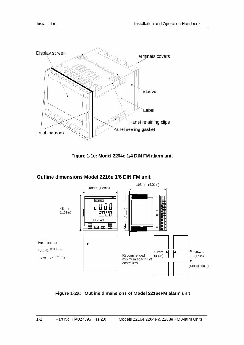
Figure 1-1c: Model 2204e 1/4 DIN FM alarm unit
Outline dimensions Model 2216e 1/6 DIN FM unit
Figure 1-2a: Outline dimensions of Model 2216eFM alarm unit
Panel retaining clips
Latching ears Panel sealing gasket
Label
Sleeve
Terminals covers Display screen
Panel cut-out 45 x 45 -0 +0.8mm
1 77x 1.77 -0 +0.03in
103mm (4.01in) 48mm (1.89in)
48mm (1.89in)
Recommended minimum spacing of controllers
38mm (1.5in)
10mm (0.4in)
(Not to scale)
Installation and Operation Handbook Installation
Models 2216e, 2204e & 2208e FM Alarm Units. Part No. HA027696 iss 2.0 1-3
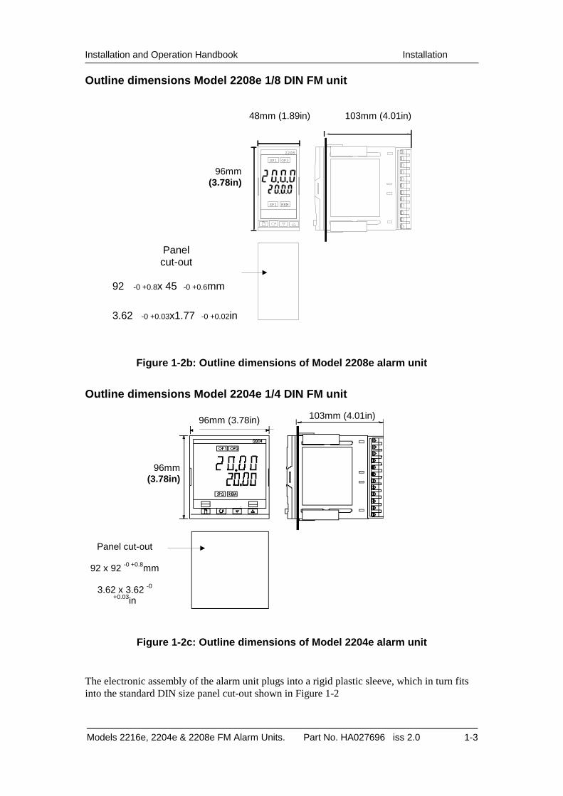
Outline dimensions Model 2208e 1/8 DIN FM unit
Figure 1-2b: Outline dimensions of Model 2208e alarm unit
Outline dimensions Model 2204e 1/4 DIN FM unit
Figure 1-2c: Outline dimensions of Model 2204e alarm unit
The electronic assembly of the alarm unit plugs into a rigid plastic sleeve, which in turn fits into the standard DIN size panel cut-out shown in Figure 1-2
Panel cut-out
92 x 92 -0 +0.8mm
3.62 x 3.62 -0
+0.03in
103mm (4.01in) 96mm (3.78in)
96mm (3.78in)
103mm (4.01in) 48mm (1.89in)
96mm(3.78in)
Panel cut-out
92 -0 +0.8x 45 -0 +0.6mm
3.62 -0 +0.03x1.77 -0 +0.02in
2208
OP1 OP2
SP2 REM

Installation Installation and Operation Handbook
1-4 Part No. HA027696 iss 2.0 Models 2216e 2204e & 2208e FM Alarm Units
INTRODUCTION
The Model 2216e is an accurate indicator and alarm unit with one, FM compliant, alarm relay output fitted as standard. It has two optional outputs 1 and 2. Output 2 can be fitted with a second FM alarm relay or Alarm Acknowledge input. Output 1 can be fitted with either: dc retransmission of PV, an additional alarm relay output, or an alarm acknowledge input. A communications option is also available.
The 2208e and 2204e FM alarm units have two FM compliant, alarm relay outputs fitted as standard. In addition they has two optional outputs 1 and 2. Output 1 can be fitted with either: dc retransmission of PV, an additional alarm relay output, or an alarm acknowledgement input. Output 2 can be fitted with an additional, non–FM compliant alarm relay output. A communications option is also available.
The FM compliant relay outputs are configurable as absolute high or low alarms. They are fixed as latching alarms, de-energised in the alarm state. It is not possible to configure them otherwise.
WARNING
Before installing the alarm unit, please read Safety Information Appendix B
Alarm unit labels The labels on the sides of the alarm unit identify the ordering code, serial number, and electrical connections.
MECHANICAL INSTALLATION
To install the alarm unit
1. Prepare the control panel cut-out to the appropriate size shown in Figure 1-2.
2. Insert the alarm unit through the cut-out.
3. Spring the upper and lower panel retaining clips into place. Secure the alarm unit in position by holding it level and pushing both retaining clips forward.
Note: If the panel retaining clips subsequently need removing, to extract the alarm unit from the control panel, they can be unhooked from the side with either your fingers or a screwdriver. Unplugging and plugging-in the alarm unit If required, the alarm unit can be unplugged from its sleeve by easing the latching ears outwards and pulling it forward out of the sleeve. When plugging the alarm unit back into its sleeve, ensure that the latching ears click into place in order to secure the IP 65 sealing.

Installation and Operation Handbook Installation
Models 2216e, 2204e & 2208e FM Alarm Units. Part No. HA027696 iss 2.0 1-5
ELECTRICAL INSTALLATION
This section consists of four topics: • Electrical connections • Outputs 1 and 2 connections • Communications connections • Typical wiring diagram
WARNING Before installing the alarm unit you must ensure that it is correctly configured for your application. Incorrect configuration could result in damage to the process being controlled, and/or personal injury. The alarm unit may either have been configured when ordered, or may need configuring now.
Wire Sizes All electrical connections are made to the screw terminals at the rear of the alarm unit. They accept wire sizes from 0.5 to 1.5 mm2 (16 to 22 awg). The terminals are protected by a clear plastic hinged cover to prevent hands or metal making accidental contact with live wires.
Electrical connections The electrical connections are shown in Figure 1-3. Please note that outputs 1 and 2 can be any one of the types shown in figure 1-4.
ELECTRICAL CONNECTIONS
Figure 1-3a: Model 2216e FM electrical connections
*The ground connection is provided as a return for internal EMC filters. It is not required for safety purposes, but must be connected to satisfy EMC requirements.
FM Alarm 1 relay output or Alarm Acknowledge input
Dig
ital C
omm
unic
atio
ns
FM Alarm 2 relay output
Ground*
Neutral
Line 85 to 264Vac Output 1
1A
1B
2A
2B
3A
3B
L
N
VI
V+
V-
HA
HB
HC
HD
HE
HF
Pt100
PV Input
-
+
T/C
+
PV
-
Installation Installation and Operation Handbook
1-6 Part No. HA027696 iss 2.0 Models 2216e 2204e & 2208e FM Alarm Units
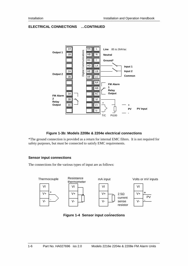
ELECTRICAL CONNECTIONS …CONTINUED
Figure 1-3b: Models 2208e & 2204e electrical connections
*The ground connection is provided as a return for internal EMC filters. It is not required for safety purposes, but must be connected to satisfy EMC requirements.
Sensor input connections
The connections for the various types of input are as follows:
Figure 1-4 Sensor input connections
VI
V+
V-
VI
V+
V-
VI
V+
V-
Thermocouple Resistance thermometer
mA input Volts or mV inputs
+
- PV
2.5Ω current sense resistor
VI
V+
V-
+
-
-
Input 1
Input 2
Common
Ground*
Neutral
Line 85 to 264Vac Output 1
Output 2
1A
1B
2A
2B
3A
3B
3C
L
N
LA
LB
LC
AA
AB
AC
VI
V+
V-
HA
HB
HC
HD
HE
HF
FM Alarm 1 Relay Output FM Alarm
2 Relay Output
Dig
ital C
omm
unic
atio
ns
PV Input -
+
T/C Pt100
+
PV
-

Installation and Operation Handbook Installation
Models 2216e, 2204e & 2208e FM Alarm Units. Part No. HA027696 iss 2.0 1-7
OUTPUTS 1 AND 2
Output 1 can be either an additional alarm relay output, 0-20mA retransmission of PV or a contact input for alarm acknowledge. Output 2 can be an additional alarm relay output or a contact input for alarm acknowledgement.
To check which outputs are installed in your particular unit refer to the ordering code and the wiring information on the alarm unit side labels.
Connections
Output 1 Input/Output 2
Module type 1A 1B 2A 2B
Relay: 2-pin (2A, 264 Vac
max.)
0-20mA, PV retransmission
+ -
Alarm acknowledge Contact input
Figure 1-5 Output 1 and 2 connections
Snubbers
The alarm unit is supplied with ‘snubbers’ (15nF +100Ω) which should be wired across the relay outputs when switching inductive loads such as mechanical contactors. The ‘snubbers’ are used to prolong contact life and to suppress interference when switching such loads. The ‘snubbers’ pass 0.6mA at 110Vac and 1.2mA at 240Vac. This may be sufficient to hold in high impedance relay coils and should not be used in such installations.
WARNING When a relay contact is used in an alarm circuit it is the user’s responsibility to ensure that the current passing through the snubber when the relay contact is open does not hold in low power electrical loads and thereby interfere with the failsafe operation of the alarm circuit.
Installation Installation and Operation Handbook
1-8 Part No. HA027696 iss 2.0 Models 2216e 2204e & 2208e FM Alarm Units
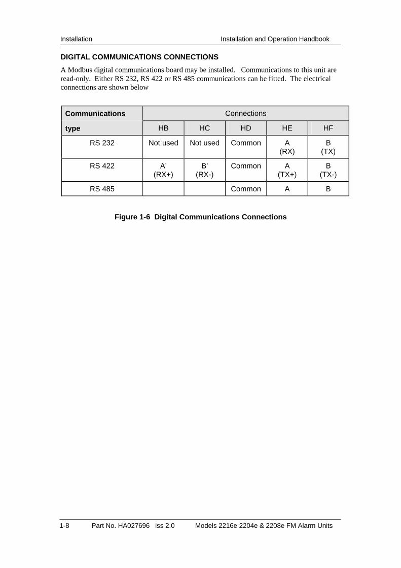
DIGITAL COMMUNICATIONS CONNECTIONS
A Modbus digital communications board may be installed. Communications to this unit are read-only. Either RS 232, RS 422 or RS 485 communications can be fitted. The electrical connections are shown below
Communications Connections
type HB HC HD HE HF
RS 232 Not used Not used Common A (RX)
B (TX)
RS 422 A’ (RX+)
B’ (RX-)
Common A (TX+)
B (TX-)
RS 485 Common A B
Figure 1-6 Digital Communications Connections

Installation and Operation Handbook Installation
Models 2216e, 2204e & 2208e FM Alarm Units. Part No. HA027696 iss 2.0 1-9
Example Wiring of EIA-485 serial communication links
HE -
HF +
HD
2204 and 2208Alarm Units
Local
LocalEarth
Com
Note:All resistors are 220 ohm 1/4W carbon composition.Local grounds are at equipotential. Where equipotential is not available wire intoseparate zones using a galvanic isolator.
A
B
Universial Converter
RXTXCom
Com TXRX
Up to 16alarm units orInterface Units maybe included on thenetwork
232
Com B A
Com
A
B
GalvanicIsolationBarrier
Com
A
B
Com
AB
Local Earth
Area 1 Area 2
Area 1
Area 1 Com
AB
Area 1
Area 1
Earth
UniversalConverter
HE
HF
HD
2204
Alarm Units
HE
HF
HD
2204 and 2208Alarm Units
For safety reasons,do not connect tolocal earth here.
Figure 1-7 EIA-485 wiring
EIA-485 is a 2-wire connection which allows up to 16 alarm units to be multi-dropped from a single communications link over a distance of up to 1.2Km. To ensure reliable operation of the communications link, (without data corruption due to noise or line reflections) the connections between the alarm unit should be made using a twisted pair of wires inside a screened cable with the connections terminated with resistors in the manner shown in this diagram.

Installation Installation and Operation Handbook
1-10 Part No. HA027696 iss 2.0 Models 2216e 2204e & 2208e FM Alarm Units
Installation and Operation Handbook Installation
Models 2216e, 2204e & 2208e FM Alarm Units. Part No. HA027696 iss 2.0 2-1
Chapter 2 OPERATION
Contents
• FRONT PANEL LAYOUTS
• POWER UP
• ALARMS MESSAGES
• PARAMETER ACCESS AND ADJUSTMENT
• NAVIGATION DIAGRAM
• PARAMETER TABLES
• ALARM MODES
• DIAGNOSTIC ALARMS
Installation Installation and Operation Handbook
2-2 Part No. HA027696 iss 2.0 Models 2216e 2204e & 2208e FM Alarm Units
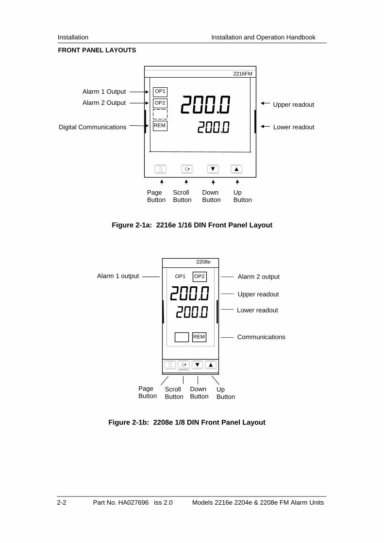
FRONT PANEL LAYOUTS
Figure 2-1a: 2216e 1/16 DIN Front Panel Layout
Page Button
Scroll Button
Down Button
Up Button
Communications
Alarm 1 output Alarm 2 output
Upper readout
Lower readout
200.0 200.0
OP1 OP2
REM
2208e
Figure 2-1b: 2208e 1/8 DIN Front Panel Layout
Upper readout
Lower readout
Down Button
Page Button
Scroll Button
Up Button
Digital Communications
Alarm 1 Output
200.0 200.0
OP1
OP2
2216FM
REM
Alarm 2 Output
Installation and Operation Handbook Installation
Models 2216e, 2204e & 2208e FM Alarm Units. Part No. HA027696 iss 2.0 2-3
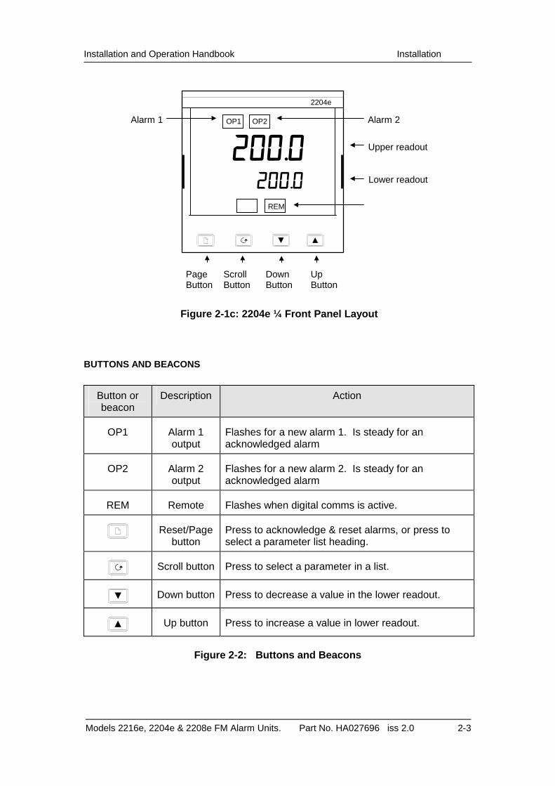
BUTTONS AND BEACONS
Button or beacon
Description Action
OP1 Alarm 1 output
Flashes for a new alarm 1. Is steady for an acknowledged alarm
OP2 Alarm 2 output
Flashes for a new alarm 2. Is steady for an acknowledged alarm
REM Remote Flashes when digital comms is active.
Reset/Page button
Press to acknowledge & reset alarms, or press to select a parameter list heading.
Scroll button Press to select a parameter in a list.
Down button Press to decrease a value in the lower readout.
Up button Press to increase a value in lower readout.
Figure 2-2: Buttons and Beacons
Upper readout
Lower readout
Down Button
Page Button
Scroll Button
Up Button
Alarm 2 Alarm 1
200.0 200.0
OP1 OP2
2204e
REM
Figure 2-1c: 2204e ¼ Front Panel Layout

Installation Installation and Operation Handbook
2-4 Part No. HA027696 iss 2.0 Models 2216e 2204e & 2208e FM Alarm Units
POWER UP
On power up the unit runs through a self-test sequence for about three seconds and then displays the temperature or process value (PV) in the upper readout. This is called the Home display. The Home display can be configured to display the just the PV, or the PV with either alarm setpoint 1 or alarm setpoint 2 in the lower readout.
Figure 2-3: Home display
Note: You can get back to the Home display at any time by pressing and together. Alternatively you will always be returned to the Home display if no button is pressed for 45 seconds or whenever the power is turned on.
ALARM MESSAGES If the unit detects an alarm, it will flash a message in the lower readout of the Home display. A new alarm will be displayed as a double flash followed by a pause. Old (acknowledged) alarms will be displayed as a single flash followed by a pause. In the case of alarm 1 and alarm 2, the front panel beacons OP1 and OP2 will flash if a new alarm occurs.
To acknowledge an alarm press the button. After the alarm has been acknowledged the beacon will be lit constantly.
When the alarm condition is corrected, an alarm acknowledge will clear the beacon and the alarm relay will return to the safe state. If there is more than one alarm condition, the display cycles through all the relevant alarm messages. The alarm messages and their meanings are as follows.
Alarm message What it means
-FSH* Full Scale High alarm
-FSL* Full Scale Low alarm
S.br Sensor Break. The input is open circuit
Pwr.F Power failure alarm.
Table 2-4: Alarm messages
*In place of the dash, the first character will indicate the alarm number
Measured temperature 200.0 200.0 200.0 200.0
2216FM

Installation and Operation Handbook Installation
Models 2216e, 2204e & 2208e FM Alarm Units. Part No. HA027696 iss 2.0 2-5
PARAMETERS ACCESS AND ADJUSTMENT
Figure 2-5, the navigation diagram shows all of the operation parameters potentially available. In practice the parameters that appear will depend on the configuration of the unit. E.g. if alarm 3 has not been configured it will not appear as a parameter in the alarm list.
The shaded boxes in the diagram indicate parameters that are hidden in normal operation. To see all the available parameters, you must select ‘Full’ access level. For more information about this, see Chapter 3, Access Levels.
The parameters are arranged in lists as shown in the navigation diagram. Each list has a list header. The list headers are:
Home list Alarm list
Input list Communications list
Access list
To step through the list headers press the Page button . You can recognise a list header by the fact that it always displays ‘LiSt’ in the lower readout. Depending upon how your alarm unit has been configured, a single press may momentarily flash the display units. In this case, a double press will be necessary to take you to the first list header. Continued
pressing of the button will step through the list headers, eventually returning you to the Home display. Example list header display
In the above example, AL is the Alarm list header. List headers are always read-only.
To step through the parameters within a particular list, press the Scroll button . When you reach the end of a list you will return to the list header. From within a list you can return to the list header at any time by pressing the Page button
.
Example parameter display
The upper readout shows the name of the parameter and the lower readout its value. In the above example, the parameter mnemonic is 1FSL (indicating Alarm 1, full scale low), and the parameter value is 10.0..
Alterable parameters can be changed by pressing the or buttons. Two seconds after releasing either button, the display blinks to show that the new value has been accepted
The parameter tables later in this chapter list all the parameter names and their meaning.
List name
Always displays ‘LiSt’
Parameter name
Parameter value

Installation Installation and Operation Handbook
2-6 Part No. HA027696 iss 2.0 Models 2216e 2204e & 2208e FM Alarm Units
NAVIGATION DIAGRAM
Figure 2-5: Navigation diagram
PARAMETER TABLES
Name Parameter Description
Home list diSP Home display configuration Std Standard (PV only
displayed) A1.SP Alarm 1 setpoint in
lower display A2.SP Alarm 2 setpoint in
lower display C.id Customer defined Instrument
id
AL Alarm list 1--- Alarm 1 setpoint 2--- Alarm 2 setpoint 3--- Alarm 3 setpoint 4--- Alarm 4 setpoint hY Alarm hystersis hy.EV Event output hystersis
In place of dashes, the last three characters indicate the alarm type as follows:
FSH Full scale high alarm FSL Full scale low alarm
iP Input list FiLt Input filter time constant. 1.0
to 999.9 seconds OFST Process value calibration
offset
CJC° Measured cold junction temperature in ºC
mV Millivolt inputs
cmS Comms list Addr Communications Address
Note: The instrument must be powered off and on to implement the comms address change.
ACCS Access List codE Full and Edit level password
entry Goto Goto level - OPEr, FuLL, Edit or
conF ConF Configuration level password
entry
Note: After selecting the password value wait 2 to 3 seconds for the unit to verify.
Home List
70 70 °F
AL LiSt
iP LiSt
CmS LiSt
ACCS LiSt
70 °f
diSP Std
C.id Std
1--- 0
2--- 400
3--- 0
4--- 0
hy 1.0
hy.EV 1.0
FiLt 1.6
OFST 0.0
CJC 27.5
mV 0.05
Addr 1
Installation and Operation Handbook Installation
Models 2216e, 2204e & 2208e FM Alarm Units. Part No. HA027696 iss 2.0 2-7
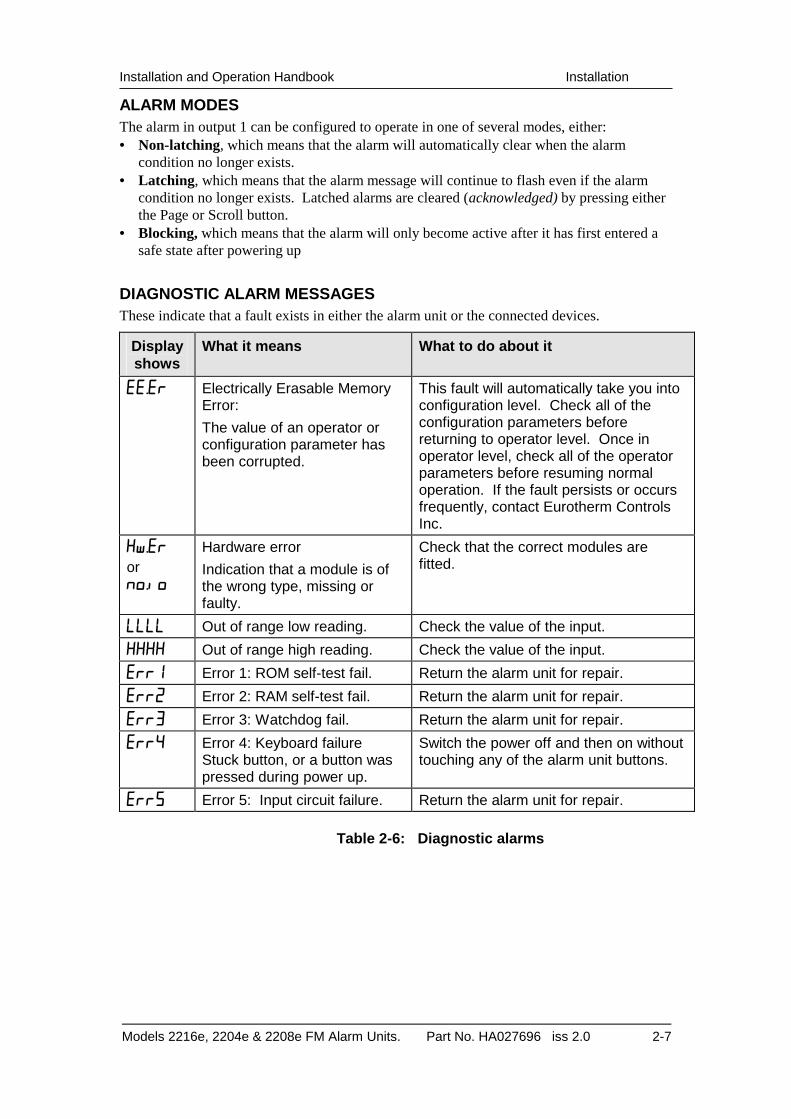
ALARM MODES The alarm in output 1 can be configured to operate in one of several modes, either: • Non-latching, which means that the alarm will automatically clear when the alarm
condition no longer exists. • Latching, which means that the alarm message will continue to flash even if the alarm
condition no longer exists. Latched alarms are cleared (acknowledged) by pressing either the Page or Scroll button.
• Blocking, which means that the alarm will only become active after it has first entered a safe state after powering up
DIAGNOSTIC ALARM MESSAGES These indicate that a fault exists in either the alarm unit or the connected devices.
Display shows
What it means What to do about it
EE.Er Electrically Erasable Memory Error:
The value of an operator or configuration parameter has been corrupted.
This fault will automatically take you into configuration level. Check all of the configuration parameters before returning to operator level. Once in operator level, check all of the operator parameters before resuming normal operation. If the fault persists or occurs frequently, contact Eurotherm Controls Inc.
HW.Er
or no.io
Hardware error
Indication that a module is of the wrong type, missing or faulty.
Check that the correct modules are fitted.
LLLL Out of range low reading. Check the value of the input.
HHHH Out of range high reading. Check the value of the input.
Err1 Error 1: ROM self-test fail. Return the alarm unit for repair.
Err2 Error 2: RAM self-test fail. Return the alarm unit for repair.
Err3 Error 3: Watchdog fail. Return the alarm unit for repair.
Err4 Error 4: Keyboard failure Stuck button, or a button was pressed during power up.
Switch the power off and then on without touching any of the alarm unit buttons.
Err5 Error 5: Input circuit failure. Return the alarm unit for repair.
Table 2-6: Diagnostic alarms

Installation Installation and Operation Handbook
2-8 Part No. HA027696 iss 2.0 Models 2216e 2204e & 2208e FM Alarm Units

Installation and Operation Handbook Access Levels
Model 2216e, 2208e & 2204e FM Alarm Units 3-1
Chapter 3 ACCESS LEVELS This chapter describes the different levels of access to the parameters within the alarm unit.
There are three topics:
• THE DIFFERENT ACCESS LEVELS
• SELECTING AN ACCESS LEVEL
• EDIT LEVEL
THE DIFFERENT ACCESS LEVELS
There are four access levels:
• Operator level, which will normally be used to operate the alarm unit
• Full level, to gain access to all operator parameters. This gives access to hidden parameters – used, for instance, for commissioning.
• Edit level, which is used hide or ‘promote’ parameters and define whether they are read only or alterable.
• Configuration level which is used to set up the fundamental characteristics of the unit.
Access
level
Display shows
What you can do
Password Protected
Operator OPEr In this level operators can view and adjust the value of parameters defined in Edit level (see below).
No
Full FuLL In this level all the operator parameters relevant to a particular configuration are visible. All alterable parameters may be adjusted.
Yes
Edit Edit In Edit level you define which parameters an operator will be able to access. You can hide or reveal complete lists and individual parameters within each list. You can make parameters read-only or alterable.
Yes
Configuration
conf Configuration sets up the fundamental characteristics of the unit. See Chapter 4
Yes
Figure 3-1: Access levels

Access Levels Installation and Operation Handbook
3-2 Models 2216e, 2208e &2204e Alarm units
SELECTING AN ACCESS LEVEL
Access to Full, Edit and Configuration levels is protected by a password.
Access list header
Press until you reach the access list header ACCS. Press the Scroll button
Password entry
The password is entered from the CodE display.
Press or to enter the password. The default password is 1. When the correct password has been entered, there is a two second delay after which the lower readout will change to PASS. Note: If the password has been set to 0, access will be permanently enabled and the lower readout will always show PASS Press the Scroll button to proceed to the Goto display. (If an incorrect password has been entered, pressing Scroll will simply return you to the access list header.)

Installation and Operation Handbook Access Levels
Model 2216e, 2208e & 2204e FM Alarm Units 3-3
Level selection
Press and to select the desired access level as follows: OPEr: Operator level FuLL: Full level Edit: Edit level conF: Configuration level Press the Scroll button
If you selected OPEr, FuLL or Edit level you will be returned to the ACCS list header in the level that you have chosen.
Configuration password
When the ConF display appears, you must enter the Configuration password to gain access to
Configuration level. Press or to enter the password. The default configuration password is 2. If you want to change the configuration password, see Chapter 4, Configuration Press the Scroll button
Configuration level
The first display of configuration is shown. See chapter 4, Configuration for details of the configuration parameters and also how to leave configuration level.
Returning to Operator Level
To return to operator level from either FuLL or Edit level, select the ACCS list, press scroll twice to the Goto display and select OPEr. In Edit level the alarm unit will automatically return to operator level if no button is pressed for 45 seconds. If an alarm is present in the process, this time is reduced to 10 seconds.
Alternative path if ConF selected
3-4 2216FM Alarm Unit
Access Levels Installation and Operation Handbook
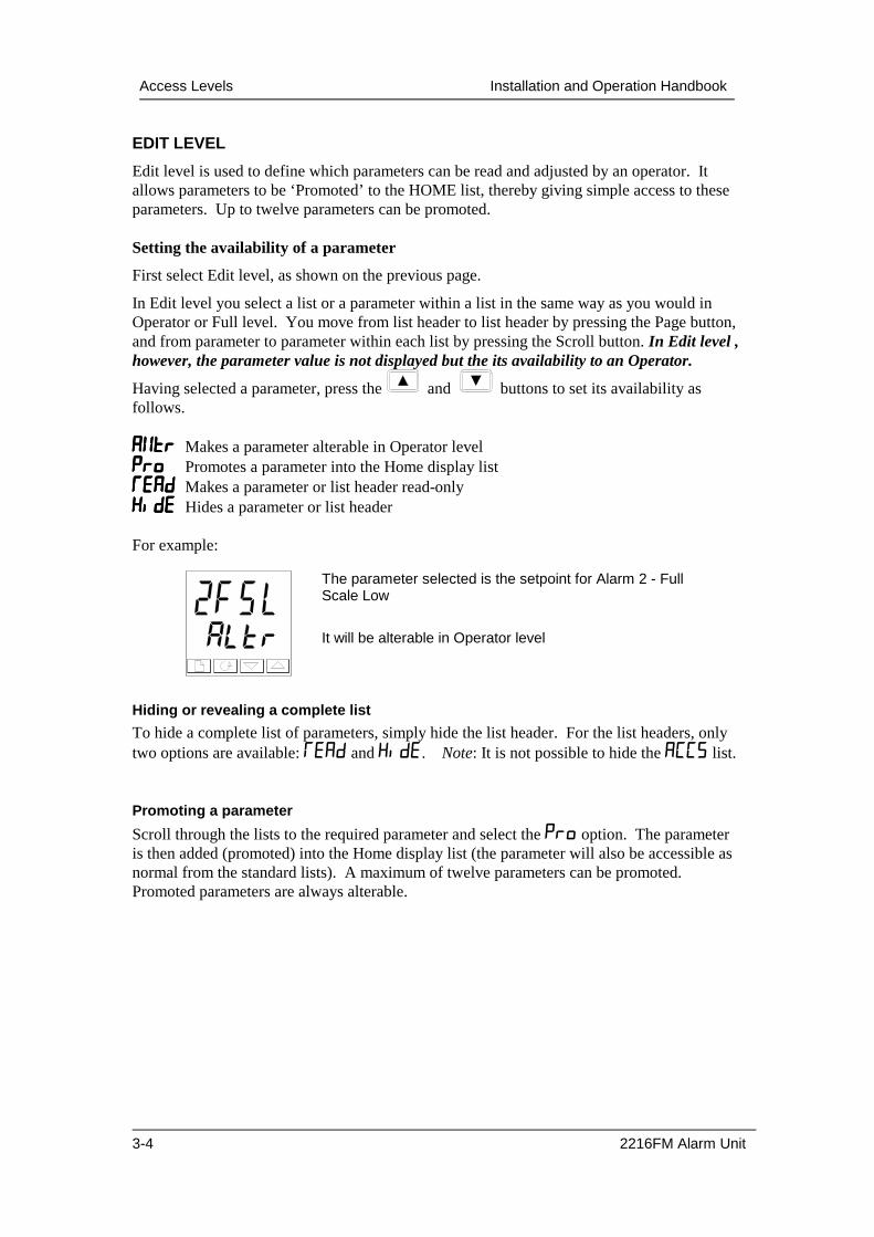
EDIT LEVEL
Edit level is used to define which parameters can be read and adjusted by an operator. It allows parameters to be ‘Promoted’ to the HOME list, thereby giving simple access to these parameters. Up to twelve parameters can be promoted. Setting the availability of a parameter
First select Edit level, as shown on the previous page.
In Edit level you select a list or a parameter within a list in the same way as you would in Operator or Full level. You move from list header to list header by pressing the Page button, and from parameter to parameter within each list by pressing the Scroll button. In Edit level , however, the parameter value is not displayed but the its availability to an Operator.
Having selected a parameter, press the and buttons to set its availability as follows. AltrAltrAltrAltr Makes a parameter alterable in Operator level ProProProPro Promotes a parameter into the Home display list REAdREAdREAdREAd Makes a parameter or list header read-only HidEHidEHidEHidE Hides a parameter or list header For example:
Hiding or revealing a complete list
To hide a complete list of parameters, simply hide the list header. For the list headers, only two options are available: REAd and HidE. Note: It is not possible to hide the ACCS list.
Promoting a parameter
Scroll through the lists to the required parameter and select the Pro option. The parameter is then added (promoted) into the Home display list (the parameter will also be accessible as normal from the standard lists). A maximum of twelve parameters can be promoted. Promoted parameters are always alterable.
The parameter selected is the setpoint for Alarm 2 - Full Scale Low
It will be alterable in Operator level
Installation and Operation Handbook Configuration
Models 2216e, 2208e & 2204e FM Alarm Units. Part No. HA027696 iss 2.0 4-1
Chapter 4 CONFIGURATION Contents:
• SELECTING CONFIGURATION LEVEL
• LEAVING CONFIGURATION LEVEL
• SELECTING A CONFIGURATION PARAMETER
• THE CONFIGURATION NAVIGATION DIAGRAM
• THE CONFIGURATION PARAMETER TABLES In configuration level you set up the following characteristics of the alarm unit:
• The display units and decimal point position.
• The input type and range
• The alarm functions
• The digital input functions
• The configuration of Alarm relays 1 and 2
• The configuration of outputs 1 and 2
• The communications configuration
• The passwords
WARNING Configuration is protected by a password and should only be carried out by a qualified person authorised to do so. Incorrect configuration could result in damage to the process being controlled and/or personal injury. It is the responsibility of the person commissioning the process to ensure that the configuration is correct.

Configuration Installation and Operation Handbook
4-2 Part No. HA027696 iss 2.0 Models 2216e, 2204e and 2208e FM Alarm Units
SELECTING CONFIGURATION LEVEL
There are two methods of selecting Configuration level: 1. If you have already powered up the alarm unit, follow the instructions given in Chapter 3:
Access levels.
2. Alternatively pressing and together when powering up the alarm unit, will take you straight to the ConF password display.
Password entry
When the ‘ConF’ display appears, press or
to enter the configuration password. The default password ‘2’. When the correct password has been entered, there is a two second delay after which the lower readout will display ‘PASS’. Note: If the password has been set to ‘0’, access is permanently enabled and the lower readout will always display ‘PASS’. Press the Scroll button to enter configuration level inSt is the first display in configuration level. (If an incorrect password has been entered, Scroll will take you to the ‘Exit’ display with ‘no’ in the lower readout. Simply press Scroll to return to the ‘ConF’ display.

Installation and Operation Handbook Configuration
Models 2216e, 2208e & 2204e FM Alarm Units. Part No. HA027696 iss 2.0 4-3
LEAVING CONFIGURATION LEVEL
To leave Configuration level and return to Operator level, press until ‘Exit’ appears.
Alternatively pressing and together will take you straight to the ‘Exit’ display.
Press or to select ‘YES’. After a two-second delay, the display will flash and revert to the Home display of Operator level.
SELECTING A CONFIGURATION PARAMETER The configuration parameters are arranged in lists as shown in Figures 5.1a and 5.1b. In this diagram each box depicts the display for a particular list header or parameter. To select a particular parameter, first select the list in which the parameter appears.
Press the button to step across the list headers. You can recognise a list header by the fact that it always displays ‘ConF’ in the lower readout. The upper readout is the name of the list.
Having selected a list header, press the Scroll button . to step down the parameters within the list. The upper readout shows the name of the parameter and the lower readout its value.
Press the or buttons to change the value of a selected parameter. For a definition of each parameter, refer to the parameter tables at the end of this chapter.
When you reach the bottom of a list, pressing will take you back to the list header. From
within a list you can return to the list header at any time by pressing the Page button . Parameter availability
The navigation diagram shows all the lists headers and parameters that can potentially be present in the alarm unit. In practice, those present will vary according to the particular configuration choices you make.
Configuration Installation and Operation Handbook
4-4 Part No. HA027696 iss 2.0 Models 2204e and 2208e FM Alarm Units
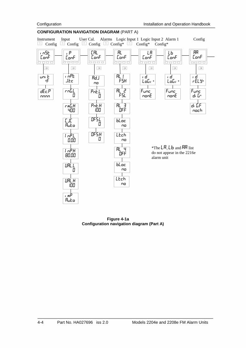
CONFIGURATION NAVIGATION DIAGRAM (PART A)
Instrument Input User Cal. Alarms Logic Input 1 Logic Input 2 Alarm 1 Config Config Config Config Config* Config* Config*
Figure 4-1a Configuration navigation diagram (Part A)
dEc.P nnnn
Adj no
OFS.L 0
Pnt.H 100
Pnt.L 0
unit oF
inST ConF
OFS.H 0
iP ConF
AL ConF
AL1 FSH
AL 2 FSL
AL 3 OFF
bLoc no
Ltch no
AL 4 OFF
bLoc no
Ltch no
id rELy*
Func diG*
AA ConF
id LoG.i*
Func nonE
Lb ConF
id LoG.i*
Func nonE
LA ConF
CAL ConF
inPt J.tc
rnG.L 0
rmG.H 400
InP.L 0.00
CJC Auto
InP.H 80.00
VAL.H 100
VAL.L 0
imP Auto
*The LA, Lb and AA list do not appear in the 2216e alarm unit
DiG.F noch

Installation and Operation Handbook Configuration
Models 2216e, 2208e & 2204e FM Alarm Units. Part No. HA027696 iss 2.0 4-5
CONFIGURATION NAVIGATION DIAGRAM (PART B)
Comms Output 1 Output 2 Alarm 2 relay Password Config Config Config Config Config
* Read only Parameters
Figure 4-1b
Configuration navigation diagram (Part B)
bAud 9600
Func Cms
id CmS
rESn Ful
PrtY nonE
HA ConF
id dC.OP
Func PV
SEnS nor
1A
ConF
id rELy*
Func diG*
2A ConF
id rELY*
Func diG*
3A ConF
ACC.P 1
CnF.P 2
Exit no
PASS ConF
Out.L 4.0
Out.H 20.0
DiG.F noch
DiG.F noch
Configuration Installation and Operation Handbook
4-6 Part No. HA027696 iss 2.0 Models 2204e and 2208e FM Alarm Units
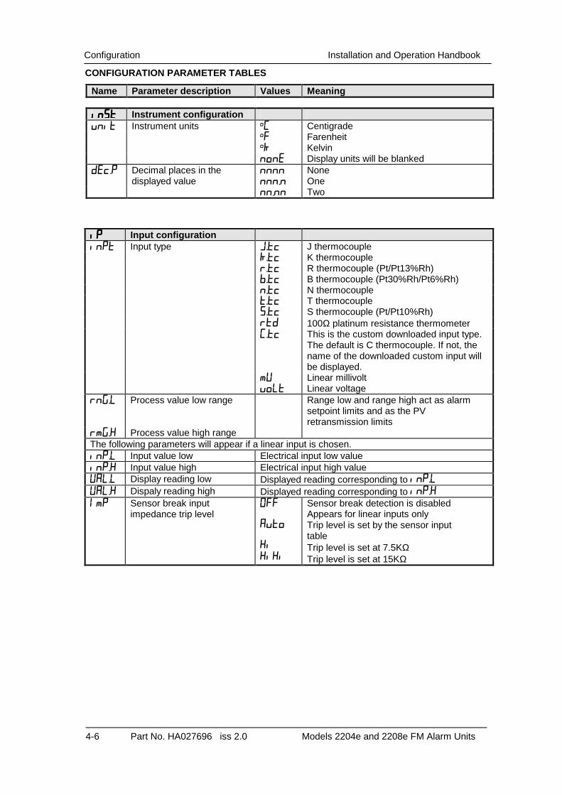
CONFIGURATION PARAMETER TABLES
Name Parameter description Values Meaning
inStinStinStinSt Instrument configuration unit Instrument units oC Centigrade oF Farenheit oK Kelvin nonE Display units will be blanked dEc.P Decimal places in the nnnn None displayed value nnn.n One nn.nn Two
iPiPiPiP Input configuration inPt Input type J.tc J thermocouple K.tc K thermocouple r.tc R thermocouple (Pt/Pt13%Rh) b.tc B thermocouple (Pt30%Rh/Pt6%Rh) n.tc N thermocouple t.tc T thermocouple S.tc S thermocouple (Pt/Pt10%Rh) rtd 100Ω platinum resistance thermometer C.tc This is the custom downloaded input type.
The default is C thermocouple. If not, the name of the downloaded custom input will be displayed.
mV Linear millivolt voLt Linear voltage rnG.L Process value low range Range low and range high act as alarm
setpoint limits and as the PV retransmission limits
rmG.H Process value high range The following parameters will appear if a linear input is chosen. inP.L Input value low Electrical input low value inP.H Input value high Electrical input high value VAL.L Display reading low Displayed reading corresponding to inp.L VAL.H Dispaly reading high Displayed reading corresponding to inp.H ImP Sensor break input
impedance trip level Off Auto Hi HiHi
Sensor break detection is disabled Appears for linear inputs only Trip level is set by the sensor input table Trip level is set at 7.5KΩ Trip level is set at 15KΩ

Installation and Operation Handbook Configuration
Models 2216e, 2208e & 2204e FM Alarm Units. Part No. HA027696 iss 2.0 4-7
Name Parameter description Values
CALCALCALCAL User Calibration enable Description AdJ User Calibration enable no User calibration disabled. – Always set to 0 YES User calibration enabled
ALALALAL Alarm configuration Values AL1 Alarm 1 Type OFF Alarm 1 disabled FSL Full scale low alarm FSH Full scale high alarm AL2 Alarm 2 Type OFF Alarm 2 disabled FSL Full scale low alarm FSH Full scale high alarm AL3 Alarm 3 Type OFF Alarm 3 disabled FSL Full scale low alarm FSH Full scale high alarm bLoc Alarm 3 Blocking no No alarm blocking YES Alarm blocking active. The alarm will be
‘blocked’ until it has first entered a good state.
Ltch Alarm 3 Latching mode no Non-latching alarm Auto Latching alarm with automatic reset. If the
alarm is acknowledged it will automatically reset when it is no longer true
man Latching alarm with manual reset. The alarm can only be reset when it is no longer true.
Evnt Event output. Non-latching output with no alarm message
AL4 Alarm 4 Type OFF Alarm 3 disabled FSL Full scale low alarm FSH Full scale high alarm bLoc Alarm 4 Blocking no No alarm blocking YES Alarm blocking active. The alarm will be
‘blocked’ until it has first entered a good state.
Ltch Alarm 4 Latching mode no Non-latching alarm Auto Latching alarm with automatic reset. If the
alarm is acknowledged it will automatically reset when it is no longer true
man Latching alarm with manual reset. The alarm can only be reset when it is no longer true.
Evnt Event output. Non-latching output with no alarm message

Configuration Installation and Operation Handbook
4-8 Part No. HA027696 iss 2.0 Models 2204e and 2208e FM Alarm Units
LALALALA Logic input 1 configuration Functions Action on contact closure id Identity of input LoG.i Logic input Func Function nonE None Ac.A1 Acknowledge alarm 1 Ac.a2 Acknowledge alarm 2 Ac.a3 Acknowledge alarm 3 Ac.a4 Acknowledge alarm 4 Ac.AL Acknowledge all alarms Ac.PF Acknowledge power fail alarm
LbLbLbLb Logic input 2 configuration Functions Action on contact closure As per Logic input LA.
AAAAAAAA Alarm 1 relay output Functions Meaning id Identity of output rELy Relay (read only) Func Function diG Digital function (read only) diGF Digital functions nocH No change CLr Disable power fail alarm Pwr.F Power fail alarm enabled.
When power fails the alarm 2 output will be de-energised on power-up.
HAHAHAHA Comms module configuration Functions Meaning id Identity of the option installed cmS Comms module Func Function nonE Comms disabled cmS Comms enabled bAud Baud Rate 1200, 2400, 4800, 9600, 19.20 (19,200) Prty Comms Parity nonE No parity EVEn Even parity Odd Odd parity rESn Resolution int
FuLL Integer Full

Installation and Operation Handbook Configuration
Models 2216e, 2208e & 2204e FM Alarm Units. Part No. HA027696 iss 2.0 4-9
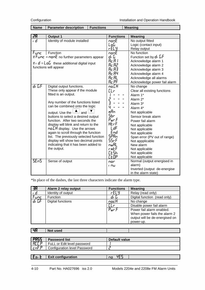
Name Parameter description Functions Meaning
1A1A1A1A Output 1 Functions Meaning id Identity of module installed nonE No output fitted rELY Relay output dC.OP Dc output (retransmission) LoG Logic (contact input) SSr Triac output Func Function nonE No function diG Function set by diG.F. Only
appears if output is relay or triac
PV Retransmission of PV. Only appears if DC output fitted
If Func = none no further parameters appear
Ac.A1 Acknowledge alarm 1 Ac.A2 Acknowledge alarm 2 Ac.A3 Acknowledge alarm 3 Ac.A4 Acknowledge alarm 4 Ac.AL Acknowledge all alarms
If id = LoG these additional digital input functions will appear
Ac.PF Acknowledge power fail alarm diG.F Digital output functions. no.CH No change These only appear if the module
fitted is an output. Any number of the functions listed can be combined onto the logic
output. Use the and buttons to select a desired output function. After two seconds the display will blink and return to the no.CH display. Use the arrows again to scroll through the function list. The previously selected function display will show two decimal points indicating that it has been added to the output.
CLr 1 - - - 2 - - - 3 - - - 4 - - - man Sbr Pwr.F HtrF LdF End SPAn SSrF nwAL rmtF CtSh CtOP
Clear all existing functions Alarm 1* Alarm 2* Alarm 3* Alarm 4* Not applicable Sensor break alarm Power fail alarm Not applicable Not applicable Not applicable Span error (PV out of range) Not appplicable New alarm Not applicable Not applicable Not applicable
SEnS Sense of output nor inv
Normal (output energised in alarm) Inverted (alarms de-energise in the alarm state)
Out.L Retransmission output low limit ).0 – 20.0
Out.H ).0 – 20.0
*In place of the dashes, the last three characters indicate the alarm type.
Configuration Installation and Operation Handbook
4-10 Part No. HA027696 iss 2.0 Models 2204e and 2208e FM Alarm Units
Name Parameter description Functions Meaning
2A2A2A2A Output 1 Functions Meaning id Identity of module installed nonE No output fitted Log Logic (contact input) rELy Relay output Func Function nonE No function If Func = none no further parameters appear diG Function set by diG.F
Ac.A1 Acknowledge alarm 1 Ac.A2 Acknowledge alarm 2 Ac.A3 Acknowledge alarm 3 Ac.A4 Acknowledge alarm 4 Ac.AL Acknowledge all alarms
If id = LoG these additional digital input functions will appear
Ac.PF Acknowledge power fail alarm diG.F Digital output functions. no.CH No change These only appear if the module
fitted is an output. Any number of the functions listed can be combined onto the logic
output. Use the and buttons to select a desired output function. After two seconds the display will blink and return to the no.CH display. Use the arrows again to scroll through the function list. The previously selected function display will show two decimal points indicating that it has been added to the output.
CLr 1 - - - 2 - - - 3 - - - 4 - - - man Sbr Pwr.F HtrF LdF End SPAn SSrF nwAL rmtF CtSh CtOP
Clear all existing functions Alarm 1* Alarm 2* Alarm 3* Alarm 4* Not applicable Sensor break alarm Power fail alarm Not applicable Not applicable Not applicable Span error (PV out of range) Not appplicable New alarm Not applicable Not applicable Not applicable
SEnS Sense of output nor inv
Normal (output energised in alarm) Inverted (output de-energise in the alarm state)
*In place of the dashes, the last three characters indicate the alarm type.
3A3A3A3A Alarm 2 relay output Functions Meaning id Identity of output rELy Relay (read only) Func Function diG Digital function (read only) diGF Digital functions nocH No change CLr Disable power fail alarm Pwr.F Power fail alarm enabled.
When power fails the alarm 2 output will be de-energised on power-up.
4A4A4A4A Not used
PASSPASSPASSPASS Password list Default value ACC.P FuLL or Edit level password 1 cnF.P Configuration level Password 2
ExitExitExitExit Exit configuration noYES
Installation and Operation Handbook Ordering Code
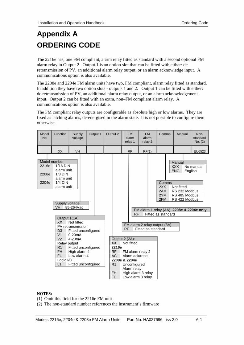
Models 2216e, 2204e & 2208e FM Alarm Units Part No. HA027696 iss 2.0 A-1
Appendix A
ORDERING CODE
The 2216e has, one FM compliant, alarm relay fitted as standard with a second optional FM alarm relay in Output 2. Output 1 is an option slot that can be fitted with either: dc retransmission of PV, an additional alarm relay output, or an alarm acknowledge input. A communications option is also available.
The 2208e and 2204e FM alarm units have two, FM compliant, alarm relay fitted as standard. In addition they have two option slots - outputs 1 and 2. Output 1 can be fitted with either: dc retransmission of PV, an additional alarm relay output, or an alarm acknowledgement input. Output 2 can be fitted with an extra, non–FM compliant alarm relay. A communications option is also available.
The FM compliant relay outputs are configurable as absolute high or low alarms. They are fixed as latching alarms, de-energised in the alarm state. It is not possible to configure them otherwise.
Model No
Function Supply voltage
Output 1 Output 2 FM alarm relay 1
FM alarm relay 2
Comms Manual Non-standard No. (2)
XX
VH
RF
RF(1)
EU0523
NOTES: (1) Omit this field for the 2216e FM unit (2) The non-standard number references the instrument’s firmware
Supply voltage VH 85-264Vac
Output 1(1A) XX Not fitted PV retransmission D3 Fitted unconfigured V1 0-20mA V2 4-20mA Relay output R1 Fitted unconfigured FH High alarm 4 FL Low alarm 4 Logic I/O L1 Fitted unconfigured
Output 2 (2A): XX Not fitted 2216e RF FM alarm relay 2 AC Alarm ack/reset 2208e & 2204e R1 Unconfigured
Alarm relay FH High alarm 3 relay FL Low alarm 3 relay
FM alarm 2 relay output (3A) RF Fitted as standard
Manual XXX No manual ENG English
FM alarm 1 relay (AA) -2208e & 2204e only RF Fitted as standard
Comms 2XX Not fitted 2AM RS 232 Modbus 2YM RS 485 Modbus 2FM RS 422 Modbus
Model number 2216e 1/16 DIN
alarm unit 2208e 1/8 DIN
alarm unit 2204e 1/4 DIN
alarm unit

Understanding The Ordering Code Installation and Operation Handbook
A-2 Part No. HA027696 iss 2.0 Models 2204 and 2208 Alarm Units
Installation and Operation Handbook Safety Information
Model 2216e, 2208e and 2204e FM Alarm Unit B-1
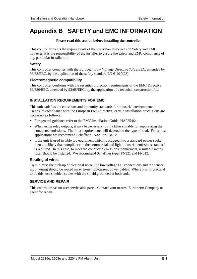
Appendix B SAFETY and EMC INFORMATION Please read this section before installing the controller
This controller meets the requirements of the European Directives on Safety and EMC, however, it is the responsibility of the installer to ensure the safety and EMC compliance of any particular installation.
Safety This controller complies with the European Low Voltage Directive 73/23/EEC, amended by 93/68/EEC, by the application of the safety standard EN 61010(93).
Electromagnetic compatibility This controller conforms with the essential protection requirements of the EMC Directive 89/336/EEC, amended by 93/68/EEC, by the application of a technical construction file.
INSTALLATION REQUIREMENTS FOR EMC
This unit satisfies the emissions and immunity standards for industrial environments. To ensure compliance with the European EMC directive, certain installation precautions are necessary as follows:
• For general guidance refer to the EMC Installation Guide, HA025464.
• When using relay outputs, it may be necessary to fit a filter suitable for suppressing the conducted emissions. The filter requirements will depend on the type of load. For typical applications we recommend Schaffner FN321 or FN612.
• If the unit is used in table top equipment which is plugged into a standard power socket, then it is likely that compliance to the commercial and light industrial emissions standard is required. In this case, to meet the conducted emissions requirement, a suitable mains filter should be installed. We recommend Schaffner types FN321 and FN612.
Routing of wires To minimise the pick-up of electrical noise, the low voltage DC connections and the sensor input wiring should be routed away from high-current power cables. Where it is impractical to do this, use shielded cables with the shield grounded at both ends.
SERVICE AND REPAIR
This controller has no user serviceable parts. Contact your nearest Eurotherm Company or agent for repair.
Safety Information Installation and Operation Handbook
B-2 2216e,2208e and 2204e FM Alarm unit
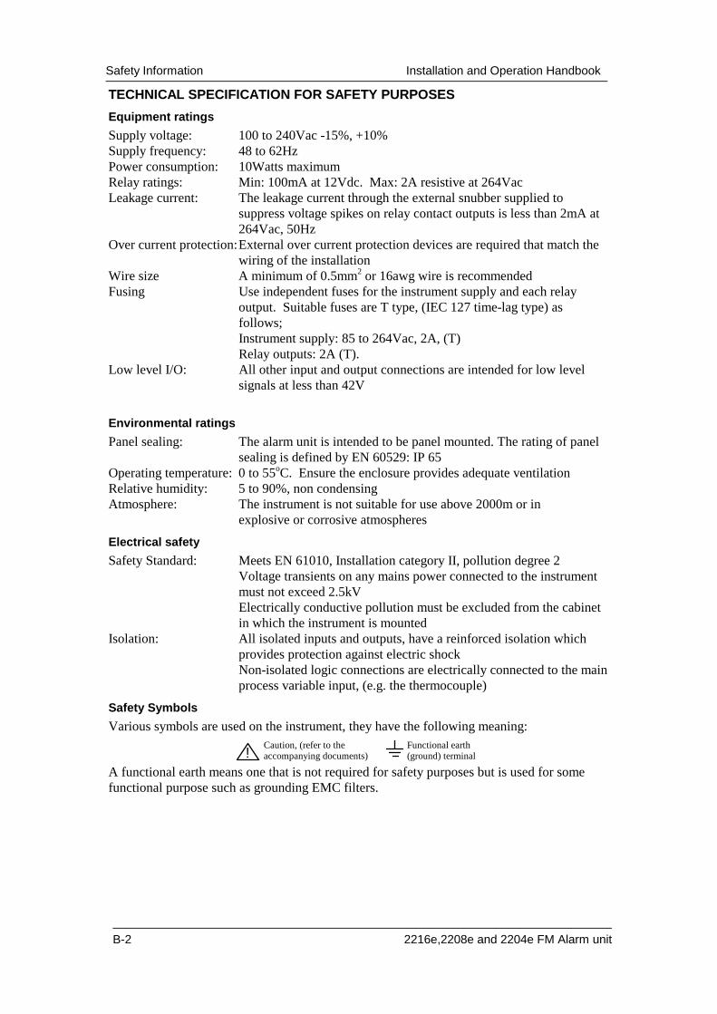
TECHNICAL SPECIFICATION FOR SAFETY PURPOSES
Equipment ratings
Supply voltage: 100 to 240Vac -15%, +10% Supply frequency: 48 to 62Hz Power consumption: 10Watts maximum Relay ratings: Min: 100mA at 12Vdc. Max: 2A resistive at 264Vac Leakage current: The leakage current through the external snubber supplied to
suppress voltage spikes on relay contact outputs is less than 2mA at 264Vac, 50Hz
Over current protection: External over current protection devices are required that match the wiring of the installation
Wire size A minimum of 0.5mm2 or 16awg wire is recommended Fusing Use independent fuses for the instrument supply and each relay
output. Suitable fuses are T type, (IEC 127 time-lag type) as follows;
Instrument supply: 85 to 264Vac, 2A, (T) Relay outputs: 2A (T). Low level I/O: All other input and output connections are intended for low level
signals at less than 42V
Environmental ratings
Panel sealing: The alarm unit is intended to be panel mounted. The rating of panel sealing is defined by EN 60529: IP 65
Operating temperature: 0 to 55oC. Ensure the enclosure provides adequate ventilation Relative humidity: 5 to 90%, non condensing Atmosphere: The instrument is not suitable for use above 2000m or in explosive or corrosive atmospheres
Electrical safety
Safety Standard: Meets EN 61010, Installation category II, pollution degree 2 Voltage transients on any mains power connected to the instrument must not exceed 2.5kV Electrically conductive pollution must be excluded from the cabinet in which the instrument is mounted
Isolation: All isolated inputs and outputs, have a reinforced isolation which provides protection against electric shock Non-isolated logic connections are electrically connected to the main process variable input, (e.g. the thermocouple)
Safety Symbols
Various symbols are used on the instrument, they have the following meaning: Caution, (refer to the accompanying documents)
Functional earth (ground) terminal!
A functional earth means one that is not required for safety purposes but is used for some functional purpose such as grounding EMC filters.
Installation and Operation Handbook Safety Information
Model 2216e, 2208e and 2204e FM Alarm Unit B-3
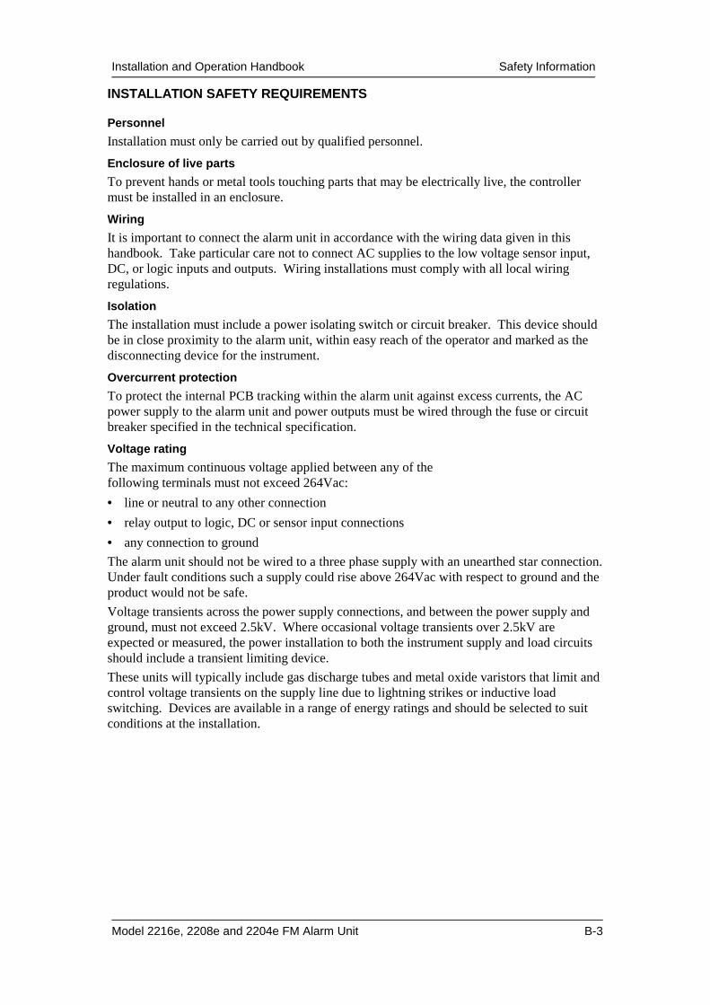
INSTALLATION SAFETY REQUIREMENTS
Personnel
Installation must only be carried out by qualified personnel.
Enclosure of live parts
To prevent hands or metal tools touching parts that may be electrically live, the controller must be installed in an enclosure.
Wiring
It is important to connect the alarm unit in accordance with the wiring data given in this handbook. Take particular care not to connect AC supplies to the low voltage sensor input, DC, or logic inputs and outputs. Wiring installations must comply with all local wiring regulations.
Isolation
The installation must include a power isolating switch or circuit breaker. This device should be in close proximity to the alarm unit, within easy reach of the operator and marked as the disconnecting device for the instrument.
Overcurrent protection
To protect the internal PCB tracking within the alarm unit against excess currents, the AC power supply to the alarm unit and power outputs must be wired through the fuse or circuit breaker specified in the technical specification.
Voltage rating
The maximum continuous voltage applied between any of the following terminals must not exceed 264Vac:
• line or neutral to any other connection
• relay output to logic, DC or sensor input connections
• any connection to ground
The alarm unit should not be wired to a three phase supply with an unearthed star connection. Under fault conditions such a supply could rise above 264Vac with respect to ground and the product would not be safe.
Voltage transients across the power supply connections, and between the power supply and ground, must not exceed 2.5kV. Where occasional voltage transients over 2.5kV are expected or measured, the power installation to both the instrument supply and load circuits should include a transient limiting device.
These units will typically include gas discharge tubes and metal oxide varistors that limit and control voltage transients on the supply line due to lightning strikes or inductive load switching. Devices are available in a range of energy ratings and should be selected to suit conditions at the installation.

Safety Information Installation and Operation Handbook
B-4 2216e,2208e and 2204e FM Alarm unit
Conductive pollution
Electrically conductive pollution must be excluded from the cabinet in which the controller is mounted. For example, carbon dust is a form of electrically conductive pollution. To secure a suitable atmosphere, install an air filter to the air intake of the cabinet. Where condensation is likely, for example at low temperatures, include a thermostatically controlled heater in the cabinet.
Grounding
The non-isolated logic has an electrical path to the sensor input. Because of this, two possible conditions need to be considered:
• In some installations it is common practice to replace the temperature sensor while the alarm unit is still powered up. Under these conditions, we recommend that the shield of the temperature detector is grounded. Do not rely on grounding through the framework of the machine.
Electrostatic discharge precautions
When the controller is removed from its sleeve, some of the exposed electronic components are vulnerable to damage by electrostatic discharge from someone handling the controller. To avoid this, before handling the unplugged controller discharge yourself to ground.


![Fish & Shellfish Immunology · growth on 2216E medium, centrifuged to collect the bacteria and suspended in 0.9% saline [24,25]. The number of bacteria in the suspensionwas measured](https://img.pdfslide.net/doc/110x75/6124cdb457adcb7c9d3accf2/fish-shellish-growth-on-2216e-medium-centrifuged-to-collect-the-bacteria.jpg)