Embed Size (px)
Citation preview
- Do not store or use gasoline or other flammable vapors and liquids in the vicinity of this or any other appliance.
- WHAT TO DO IF YOU SMELL GAS• Do not try to light any appliance. • Do not touch any electrical switch; do not use
any phone in your building. • Leave the building immediately.• Immediately call your gas supplier from a neigh-
bor’s phone. Follow the gas supplier’s instruc-tions.
• If you cannot reach your gas supplier, call the fire department.
- Installation and service must be performed by a qualified installer, service agency or the gas supplier.
WARNING:
FIRE OR EXPLOSION HAZARDFailure to follow safety warnings exactly could result in serious injury, death, or property damage.
AVERTISSEMENT:
RISQUED’INDENDIE OU D’EXPLOSIONLe non-respect Des avertissements de sécurité pourrait d’entraîner des blessures graves, la mort ou des dommages matériels.
- Ne pas entreposer ni utilizer d’essence ni d’autres vapeurs ou liquides inflammables dans le voisinage de cet appareil ou de tout autre appareil.
- QUE FAIRE SI VOUS SENTEZ UNE ODEUR DE GAZ:
• Ne pas tenter d’allumer d’appareil.• Ne touchez à aucan interrupteur. Ne pas vous servir
des téléphones se trouvant dans le bâtiment où vous trouvez.
• Sortez immédiatement de bâtiment.• Appelez immédiatement votre fournisseur de
gaz depuis un voisin. Suivez les instructions du fournisseur.
• Si vous ne pouvez rejoindre le fournisseur de gaz, appelez le service des incindies.
- L’installation et l’entretien doivent être assurés par un installateur ou un service d’entretien qualifié ou par le fournisseur de gaz.
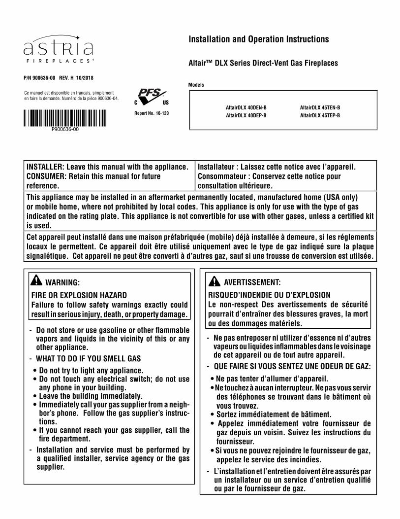
INSTALLER: Leave this manual with the appliance.CONSUMER: Retain this manual for future reference.
Installateur : Laissez cette notice avec l’appareil.Consommateur : Conservez cette notice pour consultation ultérieure.
This appliance may be installed in an aftermarket permanently located, manufactured home (USA only) or mobile home, where not prohibited by local codes. This appliance is only for use with the type of gas indicated on the rating plate. This appliance is not convertible for use with other gases, unless a certified kit is used.Cet appareil peut installé dans une maison préfabriquée (mobile) déjà installée à demeure, si les réglements locaux le permettent. Ce appareil doit être utilisé uniquement avec le type de gaz indiqué sure la plaque signalétique. Cet appareil ne peut être converti à d’autres gaz, sauf si une trousse de conversion est utilsée.
Installation and Operation Instructions
Models
C US
Report No. 16-120
Ce manuel est disponible en francais, simplement en faire la demande. Numéro de la pièce 900636-04.
P/N 900636-00 REV. H 10/2018
Altair™ DLX Series Direct-Vent Gas Fireplaces
AltairDLX 45TEN-BAltairDLX 45TEP-B
AltairDLX 40DEN-BAltairDLX 40DEP-B
P900636-00
General Information900636-00H, 10/2018
Innovative Hearth ProductsAltair™ DLX Series Direct-Vent Gas Fireplaces
2
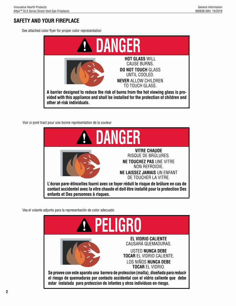
DANGER HOT GLASS WILLCAUSE BURNS.
DO NOT TOUCH GLASSUNTIL COOLED.
NEVER ALLOW CHILDRENTO TOUCH GLASS.
A barrier designed to reduce the risk of burns from the hot viewing glass is pro-vided with this appliance and shall be installed for the protection of children and other at-risk individuals.
DANGER
PELIGRO
VITRE CHAUDE RISQUE DE BRÛLURES.
NE TOUCHEZ PAS UNE VITRE NON REFROIDIE.
NE LAISSEZ JAMAIS UN ENFANTDE TOUCHER LA VITRE.
EL VIDRIO CALIENTECAUSARÁ QUEMADURAS.
USTED NUNCA DEBETOCAR EL VIDRIO CALIENTE.
LOS NIÑOS NUNCA DEBETOCAR EL VIDRIO.
L’écran pare-étincelles fourni avec ce foyer réduit le risque de brûlure en cas de contact accidentel avec la vitre chaude et doit être installé pour la protection Des enfants et Des personnes à risques.
Se provee con este aparato una barrera de proteccion (malla), diseñada para reducir el riesgo de quemaduras por contacto accidental con el vidrio caliente que debe estar instalada para proteccion de infantes y otros individuos en riesgo.
Vea el volante adjunto para la representación de color adecuado
See attached color flyer for proper color representation
Voir ci-joint tract pour une bonne représentation de la couleur
SAFETY AND YOUR FIREPLACE

General Information900636-00H, 10/2018
Innovative Hearth ProductsAltair™ DLX Series Direct-Vent Gas Fireplaces
3
Afin d’éviter les brûlures graves ou les blessures, ne pas retirer l’écran de protection de la foyer qui empêche tout contact direct avec la vitre.
Suivez les instructions de sécurité ci-dessous et veillez à ce que tous les membres de votre famille soient conscients du danger de brûlure encouru :
• Les surfaces de votre foyer deviennent EXTRÊMEMENT CHAUDES !
• La vitre située à l'avant du foyer atteint des températures EXTRÊMEMENT ÉLEVÉES et peut causer de graves blessures en cas de contact.
• Tenez les enfants à l'écart du foyer lorsqu'il fonctionne. Surveillez attentivement les enfants dans les pièces où un foyer est utilisé afin d'éviter qu'ils ne soient en contact avec la vitre.
• Tenez tous les vêtements, les meubles, l'essence et tout autre liquide inflammable à l'écart du foyer.
• Même après fermeture du gaz, les surfaces du foyer restent extrêmement chaudes.
Veillez à coller les Étiquettes de mise en garde relatives à la sécurité d'utilisation à l'endroit où vous utilisez le foyer, pour rappeler à tous les utilisateurs les dangers liés aux températures élevées (Page 45).
Lisez L’information de sûreté importante (Page 5).
Para evitar quemaduras y lesiones graves, no quite el protector de malla o guardia de seguridad que evita el contacto directo con el vidrio.
Siga las instrucciones de seguridad a continuación y asegúrese de que todos en su hogar sepan acerca de este peligro de quemadura:
• ¡Las superficies de la chimenea estarán EXTREMADAMANTE CALIENTES!!
• El vidrio delante de la chimenea alcanza temperaturas EXTREMADAMENTE ALTAS y puede causar quemaduras graves si se toca.
• Mantenga a los niños alejados de la chimenea en funcionamiento. Supervise en forma cercana a los niños en cualquier cuarto donde haya una chimenea funcionando para impedir el contacto con el vidrio.
• Mantenga la ropa, mobiliario, gasolina y otros líquidos inflamables alejados de la chimenea.
• Aún después de haber apagado el gas, las superficies de la chimenea permanecen extremadamente calientes.
Asegúrese de colocar las Etiquetas de advertencia de seguridad de operación en el lugar donde enciende la chimenea, para que todos recuerden los peligros asociados con las altas temperaturas (Página 45).
Lea Información importante de seguridad (Página 5).
Seguridad y su chimenea
La sécurité et votre foyer
[FRENCH][ENGLISH] [SPANISH]
Safety and Your Fireplace
To prevent severe burns and injuries, do Not remove the barrier on the appliance which prevents direct contact with the glass.
Follow the safety instructions below and be sure everyone in your household understands this burn hazard:
• The surfaces on your fireplace get EXTREMELY HOT!
• The glass on the front of the fireplace reaches EXTREMELY HIGH temperatures and can cause severe burns if touched.
• Keep children away from an operating fireplace. Closely supervise children in any room where a fireplace is operating to prevent contact with glass.
• Keep clothing, furniture, gasoline, and other flammable liquids away from the fireplace.
• Even after the gas is turned off, fireplace surfaces remain extremely hot.
Be sure to attach the enclosed Safety-in-Operation Warnings where you turn on your fireplace, to help remind everyone of the dangers associated with high temperatures (Page 45).
Read Important Safety Information (Page 5).
All parts of your IHP fireplace get EXTREMELY HOT!
Toutes les parties de votre foyer IHP deviennent
EXTRÊMEMENT CHAUDES !
¡Todas las partes de la chimenea IHP se ponen
MUY CALIENTES!
General Information900636-00H, 10/2018
Innovative Hearth ProductsAltair™ DLX Series Direct-Vent Gas Fireplaces
4
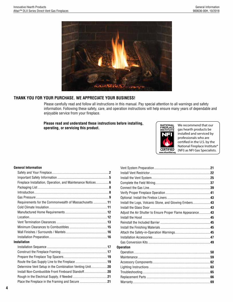
THANK YOU FOR YOUR PURCHASE. WE APPRECIATE YOUR BUSINESS!Please carefully read and follow all instructions in this manual. Pay special attention to all warnings and safety information. Following these safety, care, and operation instructions will help ensure many years of dependable and enjoyable service from your fireplace.
Please read and understand these instructions before installing, operating, or servicing this product.
We recommend that our gas hearth products be installed and serviced by professionals who are certi�ed in the U.S. by the National Fireplace Institute® (NFI) as NFI Gas Specialists.
General InformationSafety and Your Fireplace...................................................................2Important Safety Information ............................................................5Fireplace Installation, Operation, and Maintenance Notices ...............6Packaging List ...................................................................................8Introduction .......................................................................................8Gas Pressure .....................................................................................9Requirements for the Commonwealth of Massachusetts ................11Cold Climate Insulation ....................................................................11Manufactured Home Requirements .................................................12Location ...........................................................................................12Vent Termination Clearances ...........................................................13Minimum Clearances to Combustibles ............................................15Wall Finishes / Surrounds / Mantels ................................................16Installation Preparation ....................................................................16
InstallationInstallation Sequence ......................................................................17Construct the Fireplace Framing ......................................................17Prepare the Fireplace Top Spacers ...................................................19Route the Gas Supply Line to the Fireplace .....................................19Determine Vent Setup in the Combination Venting Unit ...................20Install Non-Combustible Front Fireboard Standoff ...........................20Rough in the Electrical Supply, if Needed ........................................21Place the Fireplace in the Framing and Secure ................................21
Vent System Preparation .................................................................21Install Vent Restrictor ......................................................................22Install the Vent System ....................................................................25Complete the Field Wiring ................................................................37Connect the Gas Line .......................................................................39Verify Proper Fireplace Operation ....................................................41Optional: Install the Firebox Liners ..................................................43Install the Logs, Volcanic Stone, and Glowing Embers ....................43Install the Glass Door ......................................................................43Adjust the Air Shutter to Ensure Proper Flame Appearance .............43Install the Hood ...............................................................................45Reinstall the Included Barrier ..........................................................45Install the Finishing Materials ..........................................................45Attach the Safety-in-Operation Warnings.........................................45Installation Accessories ...................................................................47Gas Conversion Kits ........................................................................49
OperationOperation .........................................................................................50Maintenance ....................................................................................59Accessory Components ...................................................................62Lighting Instructions .......................................................................63Troubleshooting ...............................................................................65Replacement Parts ..........................................................................66Warranty ..........................................................................................69

General Information900636-00H, 10/2018
Innovative Hearth ProductsAltair™ DLX Series Direct-Vent Gas Fireplaces
5
Important Safety Informa-tion1. WARNING: Do not operate appliance
with the glass front removed, cracked or broken.
2. Do not use this appliance if any part has been under water. Immediately call a qualified service technician to in-spect the appliance and to replace any part of the control system and any gas control which has been under water.
3. Due to high temperatures, the appli-ance should be located out of traffic and away from furniture and draperies.
4. Children and adults should be alerted to the hazards of high surface tem-perature and should stay away to avoid burns or clothing ignition.
5. Clothing or other flammable material should not be placed on or near the appliance.
6. Young children should be carefully supervised when they are in the same room as the appliance. Toddlers, young children, and others may be sus-ceptible to accidental contact burns. A physical barrier is recommended if there are at-risk individuals in the house. To restrict access to a fireplace or stove, install an adjustable safety gate to keep toddlers, young children, and other at-risk individuals out of the room and away from hot surfaces.
7. Any safety screen, guard or barrier removed for servicing an appliance must be replaced prior to operating the appliance.
8. Installation and repair should be done by a qualified service person. The ap-pliance should be inspected before use and at least annually by a professional service person. More frequent clean-ing may be required due to excessive lint from carpeting, bedding material, et cetera. It is imperative that control compartments, burners, and circulat-ing air passageways of the appliance be kept clean. See maintenance in-structions on Page 58.
L’information de sûreté importante1. AVERTISSEMENT. Ne pas utiliser l’appareil
si le panneau frontal en verre n’est pas en place, est craqué ou brisé.
2. Ne pas se servir de cet appareil s’il a été plongé dans l’eau, même partiellement. Faire inspecter l'appareil par un technicien qualifié et remplacer toute partie du systéme de contrôle et toute commande qui ont été plongées dans l'eau.
3. En raison des températures élevées, l’appareil devrait être installé dans un en-droit où il y a peu de circulation et loin du mobilier et des tentures.
4. Les enfants et les adultes devraient être informés des dangers que posent les tem-pératures de surface élevées et se tenir à distance afin d’éviter des brûlures ou que leurs vêtements ne s’enflamment.
5. On ne devrait pas placer de vêtements ni d’autres matières inflammables sur l’appareil ni à proximité.
6. Les jeunes enfants devraient être surveillés étroitement lorsqu’ils se trouvent dans la même pièce que l’appareil. Les tout petits, les jeunes enfants ou les adultes peuvent subir des brûlures s’ils viennent en contact avec la surface chaude. Il est recommandé d’installer une barrière physique si des personnes à risques habitent la maison. Pour empêcher l’accès à un foyer ou à un poêle, installez une barrière de sécurité ; cette mesure empêchera les tout petits, les jeunes enfants et toute autre personne à risque d’avoir accès à la pièce et aux surfaces chaudes.
7. Tout écran ou protecteur retiré pour per-mettre l’entretien de l’appareil doit être remis en place avant de mettre l’appareil en marche.
8. L’installation et la réparation devrait être confiées à un technicien qualifié. L’appareil devrait faire l’objet d’une inspection par un technicien professionnel avant d’être utilisé et au moins une fois l’an par la suite. Des nettoyages plus fréquents peuvent être nécessaires si les tapis, la literie, et cetera produisent une quantité importante de pous-sière. Il est essentiel que les compartiments abritant les commandes, les brûleurs et les conduits de circulation d’air de l’appareil soient tenus propres. Voyez les instructions d’entretien à la page 58.
Información importante de seguridad
1. ADVERTENCIA: No opere el artefacto con el frente de vidrio quitado, agrietado o roto.
2. No use este artefacto si alguna de sus partes ha estado bajo agua. Llame de inmediato a un técnico de servicio calificado para que inspeccione el artefacto y reemplace cualquier parte del sistema de control y cualquier control de gas que haya estado bajo agua.
3. Debido a las altas temperaturas, el artefacto debe situarse fuera de las áreas de tráfico y lejos del mobiliario y cortinas.
4. Se debe alertar a los niños y adultos sobre los peligros de las altas temperaturas en la superficie y que se mantengan alejados para evitar quemaduras o ignición de la ropa.
5. No debe colocarse ropa u otros materiales inflamables sobre y cerca del artefacto.
6. Se debe supervisar de cerca a los niños cuando estén en el mismo cuarto que el artefacto. Los niños pequeños, los jóvenes y otras personas pueden ser susceptibles a quemaduras por contacto accidental. Se recomienda instalar una barrera física si hay personas en riesgo en la casa. Para restringir el acceso a una chimenea o estufa, instale una puerta de seguridad ajustable para mantener a los niños pequeños, jóvenes y otras personas en riesgo fuera del cuarto y lejos de las superficies calientes.
7. Cualquier malla o resguardo de seguridad quitado para dar servicio a un artefacto, debe reinstalarse antes de operar el artefacto.
8. Una persona de servicio competente debe realizar la instalación y reparación. Una persona de servicio profesional debe inspeccionar el artefacto antes de usar al menos una vez por año. Se puede requerir limpieza más frecuente debido a la pelusa excesiva del alfombrado, del material de cobijas, etc. Es imprescindible mantener limpios los compartimientos de control, los quemadores y los pasajes de circulación del aire del artefacto. Ver las instrucciones de mantenimiento en la página 58.
IMPORTANT SAFETY INFORMATION
[English] [French] [Spanish]

General Information900636-00H, 10/2018
Innovative Hearth ProductsAltair™ DLX Series Direct-Vent Gas Fireplaces
6
APPLIANCE INSTALLATION, SERVICE, AND MAINTENANCE NOTICES
WARNING Improper installation, adjustment, alteration, service or maintenance can cause injury or property damage. Refer to this manual. For assistance or additional information consult a qualified installer, service agency or the gas supplier.
AVERTISSEMENT Une installation, un réglage,une modification, une réparation ou un entretien mal effectué peut causer des dommages matériels ou des blessures. Voir la notice de l’utilisateur qui accompagne l’appareil. Pour de l’aide ou des renseignements supplémentaires, consultez un installateur, un technicien agréé ou le fournisseur de gaz.
Only trim kit(s) supplied by the manufacturer shall be used in the installation of this fireplace.Seules des portes certifiées pour cet appareil doivent être utilisées.
These appliances must not be connected to a chimney or flue serving a separate solid fuel burning appliance.
Any change to this appliance and/or its operating controls is dangerous. Improper installation or use of this appliance can cause serious injury or death from fire, burns, explosion or carbon monoxide poisoning.
CARBON MONOXIDE POISONING: Early signs of carbon monoxide poisoning are similar to the flu with headaches, dizziness and/or nausea. If you have these signs, obtain fresh air immediately. Turn off the gas supply to the appliance and have it serviced by a qualified professional, as it may not be operating correctly. Some people are more affected by carbon monoxide than others, including pregnant women, people with heart or lung disease or anemia, those under the influence of alcohol, and those at high altitudes.
Turn off gas and electrical power to the appliance and allow it to cool before cleaning or servicing the appliance.
If the barrier becomes damaged, the barrier shall be replaced with the manufacturer’s barrier for this appliance.
Si l’écran est endommagé, il doit être remplacé par celui fournit par le fabricant de cet appareil.
For use with barrier(s) Part No(s). F1840 (40” Models), and F1903 (45” Models). Follow installation instructions.
Reinstall any barrier removed before operating the appliance. The barrier is designed to reduce the risk of burns from hot glass. Do not operate the appliance without the barrier installed.

General Information900636-00H, 10/2018
Innovative Hearth ProductsAltair™ DLX Series Direct-Vent Gas Fireplaces
7
APPLIANCE OPERATION NOTICES
WARRANTY INFORMATION
IMPORTANT SAFETY AND WARNING INFORMATION
CAUTION Hot while in operation. Do not touch. Severe Burns may result. Keep children, clothing furniture, gasoline and other liquids having flammable vapors away.
ATTENTION L’appareil est chaud lorsqu’il fonctionne. Ne pas toucher l’appareil. Risque de brûlures graves. Surveiller les enfants. Garder les vêtements, les meubles, l’essence ou autres liquides produisant des vapeur inflammables loin de l’appareil.
These fireplaces are vented gas appliances. Do not burn wood or other material in these appliances.
These appliances are designed to operate on natural gas or propane gas only. The use of other fuels or combinations of fuels will degrade the performance of this system and may be dangerous.
Provide adequate clearances around air openings and adequate accessibility clearance for service and proper operation. Never obstruct the front openings of the appliance.
These appliances are designed as supplemental heaters. Therefore, it is advisable to have an alternate primary heat source when installed in a dwelling.
Your gas appliance is covered by a limited lifetime warranty. You will find a copy of the warranty accompanying this manual. Please read the warranty to be familiar with its coverage.
Retain this manual. File it with your other documents for future reference.
Failure to comply with the installation and operating instructions provided will result in an improperly installed and operating appliance, voiding its warranty.
Do not attempt to alter or modify the construction of the appliance or its components. Any modification or alteration may void the warranty, certification, and listings of this unit.
WARNING This product can expose you to chemicals including Carbon Black, which is known to the State of California to cause cancer, and Carbon Monoxide, which is known to the State of California to cause birth defects or other reproductive harm. For more information go to www.P65Warnings.ca.gov

General Information900636-00H, 10/2018
Innovative Hearth ProductsAltair™ DLX Series Direct-Vent Gas Fireplaces
8
INSTALLATION
PACKAGING LIST
All models include
The assembled vented gas fireplace heater is packaged with:• Literature Kit (envelope in bottom compartment containing Installation and Operation Instructions (this manual),
Hot Glass Safety Flyer, and Safety-In-Operation Warning Labels)• U-Shaped Vent Restrictor (attached to Literature Kit envelope)• Hood (Inside firebox)• Remote Control and Receiver• Log Set (packaged in a carton inside the firebox)• Volcanic Stone—1 bag (in bottom compartment)• Glowing Embers—1 bag (in bottom compartment)
INTRODUCTION
These vented gas fireplace heaters are sealed combustion, air-circulating gas fireplaces designed for residential and commercial applications.Fireplaces are designed with an electronic intermittent pilot ignition system. External electrical power is required to operate these units. In the event of a power outage, four (4) AA batteries (in battery holder) provide backup power for fireplace operation (excluding the blower).
NOTE: Installation and repair should be done by a qualified service person. The fireplace should be inspected before use and at least annually by a professional service person. More frequent cleaning may be required due to excessive lint from carpeting, bedding material, etcetera. It is imperative that control compartments, burners and circulating air passageways of the fireplace be kept clean.
Remarqué : L’installation et la réparation devrait être confiées à un technicien qualifié. L’appareil devrait faire l’objet d’une inspection par un technicien professionnel avant d’être utilisé et au moins une fois l’an par la suite. Des nettoyages plus fréquents peuvent être nécessaires si les tapis, la literie, et cetera produisent une quantité importante de pous-sière. Il est essentiel que les compartiments abritant les commandes, les brûleurs et les conduits de circulation d’air de l’appareil soient tenus propres.
NOTE: Diagrams and illustrations are not necessarily shown to scale.
Approved Vent Components
These fireplaces are designed, tested and listed for operation and installation with the following vent components only:
• Secure Vent® Direct-Vent System Components,• Secure Flex® Flexible Vent Components, and • Z-FLEX® Model GA Venting Systems listed to UL1777 and ULCS635 manufactured by Flexmaster Canada
Limited.
Use only the correct size venting (4-1/2” inner and 7-1/2” outer).These approved vent system components are labeled for identification. DO NOT use any other manufacturer’s vent components with these fireplaces.
Codes and Standards
These fireplaces comply with National Safety Standards and are tested and listed by PFS Corporation (Report No. 16-120) to ANSI Z21.88 (in Canada, CSA-2.33), and CAN/CGA-2.17-M91 in both USA and Canada, as vented gas fireplace heaters.These fireplaces are listed for installation in bedrooms and manufactured homes.The installation must conform to local codes or, in the absence of local codes, with the National Fuel Gas Code, ANSI Z223.1/NFPA 54—latest edition (In Canada, the current CAN/CGA-B149.1 installation code).The fireplace, when installed, must be electrically grounded and wired in accordance with local codes or, in the absence of local codes, with the National Electrical Code, ANSI/NFPA 70—latest edition, or the Canadian Electrical Code, CSA C22.1—latest edition.

General Information900636-00H, 10/2018
Innovative Hearth ProductsAltair™ DLX Series Direct-Vent Gas Fireplaces
9
BTU Input
Table 1 - Input Rate (BTU/HR), Gas Valves
ModelsNatural Gas Propane Gas
High Rate Low Rate High Rate Low Rate
40” Models 36,000 24,000 31,000 21,000
45” Models 42,000 25,000 41,000 22,000
Table 2 - Thermal Efficiency (%)
ModelElectronic
AFUE * P4 **
40” Models 67 60
45” Models 67 65
* AFUE is a measurement of the US Department of Energy,
** Complies with CSA P.4.1-2015 “Testing Method for Measuring Annual Fireplace Efficiency. P4 (EnerGuide) is a measurement of the Canadian Office of Energy Efficiency.
Efficiencies are based on Normal input operation.
Gas Pressure
Table 3 - Inlet Line Gas PressuresFuel Minimum Maximum
Natural Gas 5” WC (1.25 kPa) 10.5” WC (2.61 kPa)
Propane 11.0” WC (2.74 kPa) 13.0” WC (3.23 kPa)
Table 4 - Manifold Outlet Gas Supply Pressure
Fuel Pressure
Natural Gas 3.5” WC (0.87 kPa)
Propane 10.0” WC (2.49 kPa)
The outlet manifold test gauge connection is provided on the valve stem of the electronic gas valve (see Figure 1A). The inlet line gas pressure test point for the electronic gas valve is shown in Figure 1B. The control valves have a 3/8” (10 mm) NPT thread inlet and outlet side of the valve.
Propane tanks are at pressures that will cause damage to valve components. Verify that the tanks have step down regulators to reduce the pressure to safe levels.
Ecoflow Electronic Gas Valve
Some parts have been removed for clarity
1/8” Inlet line gas pressure ‘test point’ plug (in control compartment)
APPLIANCES WITH ECOFLOW VALVE
Testing Inlet line Gas Pressure (Qualified Technicians Only):1. Turn off gas shutoff valve and electrical. 2. Remove 1/8” plug (shown in diagram to the right).3. Install an 1/8” nipple in place of plug.4. Connect manometer to nipple, using an 1/8” NPT air hose nipple/fitting.5. Turn on shutoff valve and check for proper inlet gas pressure.6. Reverse steps 1-5.
Figure 1B - Ecoflow INLET Line Gas Pressure Test PointFigure 1A - Gas Valve
Based on CSA P.4.1-2015
Manifold gas pressure test point (outlet)
Installation 900636-00H, 10/2018
Innovative Hearth ProductsAltair™ DLX Series Direct-Vent Gas Fireplaces
10
The appliance and its appliance main gas valve must be disconnected from the gas supply piping system during any pressure testing of that system at test pressures in excess of 1/2 psi (3.5 kPa).
The appliance must be isolated from the gas supply piping system by closing its equipment shutoff valve during any pressure testing of the gas supply piping system at test pressures equal to or less than 1/2 psi (3.5 kPa).
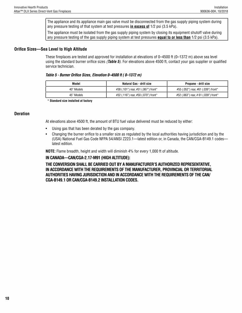
Orifice Sizes—Sea Level to High Altitude
These fireplaces are tested and approved for installation at elevations of 0–4500 ft (0–1372 m) above sea level using the standard burner orifice sizes (Table 5). For elevations above 4500 ft, contact your gas supplier or qualified service technician.
Table 5 - Burner Orifice Sizes, Elevation 0–4500 ft ( 0–1372 m)
Model Natural Gas - drill size Propane - drill size
40” Models #38 (.101”) rear, #51 (.067”) front* #55 (.052”) rear, #61 (.039”) front*
45” Models #32 (.116”) rear, #50 (.070”) front* #52 (.063”) rear, # 61 (.039”) front*
* Standard size installed at factory
Deration
At elevations above 4500 ft, the amount of BTU fuel value delivered must be reduced by either:
• Using gas that has been derated by the gas company.• Changing the burner orifice to a smaller size as regulated by the local authorities having jurisdiction and by the
(USA) National Fuel Gas Code NFPA 54/ANSI Z223.1—latest edition or, in Canada, the CAN/CGA-B149.1 codes—latest edition.
NOTE: Flame breadth, height and width will diminish 4% for every 1,000 ft of altitude.
IN CANADA—CAN/CGA-2.17-M91 (HIGH ALTITUDE):THE CONVERSION SHALL BE CARRIED OUT BY A MANUFACTURER’S AUTHORIZED REPRESENTATIVE, IN ACCORDANCE WITH THE REQUIREMENTS OF THE MANUFACTURER, PROVINCIAL OR TERRITORIAL AUTHORITIES HAVING JURISDICTION AND IN ACCORDANCE WITH THE REQUIREMENTS OF THE CAN/CGA-B149.1 OR CAN/CGA-B149.2 INSTALLATION CODES.
Installation 900636-00H, 10/2018
Innovative Hearth ProductsAltair™ DLX Series Direct-Vent Gas Fireplaces
11
COMMONWEALTH OF MASSACHUSETTS REQUIREMENTS
These appliances are approved for installation in the US state of Massachusetts if the following additional requirements are met:
• Install this appliance in accordance with Massachusetts Rules and Regulations 248 C.M.R. Sections 4.00 through 8.00.
• Installation and repair must be done by a plumber or gas fitter licensed in the Commonwealth of Massachusetts.• The flexible gas line connector used shall not exceed 36 inches (92 centimeters) in length.• The individual manual shut-off must be a T-handle type valve.
Massachusetts Horizontal Vent Requirements
In the Commonwealth of Massachusetts, horizontal terminations installed less than seven (7) feet above the finished grade must comply with the following additional requirements:
• A hard wired carbon monoxide detector with an alarm and battery back-up must be installed on the floor level where the gas fireplace is installed. The carbon monoxide detector must comply with NFPA 720, be ANSI/UL 2034 listed and be ISA certified.
A metal or plastic identification plate must be permanently mounted to the exterior of the building at a minimum height of eight (8) feet above grade and be directly in line with the horizontal termination. The sign must read, in print size no less than one-half (1/2) inch in size, GAS VENT DIRECTLY BELOW. KEEP CLEAR OF ALL OBSTRUCTIONS.
COLD CLIMATE INSULATION
For cold climate installations, seal all cracks around your fireplace with noncombustible material and wherever cold air could enter the room. It is especially important to insulate outside chase cavity between studs and under floor on which fireplace rests, if floor is above ground level. Gas line holes and other openings should be caulked or stuffed with unfaced fiberglass insulation.
NOTE: Do not use loose, or blown-in insulation in the cavity surrounding the fireplace.
If the fireplace is being installed on a cement slab in cold climates, a sheet of plywood or other raised platform can be placed underneath to prevent conduction of cold transferring to the fireplace and into the room. It also helps to seal inside surfaces and tape for maximum air tightness and caulk firestops.

Installation 900636-00H, 10/2018
Innovative Hearth ProductsAltair™ DLX Series Direct-Vent Gas Fireplaces
12
MANUFACTURED HOME REQUIREMENTS
This appliance may be installed in an aftermarket, permanently located, manufactured home (USA only) or mobile home, where not prohibited by local codes.
Cet appareil peut être installé dans une maison préfabriquée (mobile) déjà installée à demeure si les règlements locaux le permettent.
This appliance is only for use with the type of gas indicated on the rating plate. This appliance is not convertible for use with other gases, unless a certified kit is used.
Cet appareil doit être utilisé uniquement avec le type de gaz indiqué sur la plaque signalétique. Cet appareil ne peut être converti à d’autres gaz, sauf si une trousse de conversion est utilisée.
CAUTION Ensure that the cross members are not cut or weakened during installation. The structural integrity of the manufactured home floor, wall, and ceiling / roof must be maintained.
CAUTION This appliance must be grounded to the chassis of the manufactured home in accordance with local codes or in the absence of local codes, with the National Electrical Code ANSI / NFPA 70—latest edition or the Canadian Electrical Code CSA C22.1—latest edition.
LOCATION
In selecting the location, the aesthetic and functional use of the fireplace are primary concerns. However, vent system routing to the exterior and access to the fuel supply are also important.
Due to high temperatures, the fireplace should be located out of traffic and away from furniture and draperies.
En raison des températures élevées, l’appareil devrait être installé dans un endroit où il y a peu de circulation et loin du mobilier et des tentures.
The location should also be free of electrical, plumbing or other heating/air conditioning ducting.
These direct-vent fireplaces are uniquely suited for installations requiring a utility shelf positioned directly above the fireplace. Utility shelves like these are commonly used for locating television sets and decorative plants.
Be aware that this is a heat producing fireplace. Objects placed above the unit are exposed to elevated temperatures. Do not insulate the space between the fireplace and the area above it.
The minimum height from the base of the fireplace to the underside of combustible materials used to construct a utility shelf in this fashion is shown in Table 9.
Figure 2 - Typical Locations and Venting
Vertical Vent(Rear Vent)
HORIZONTAL VENT(Rear Vent Application with a chase)
HORIZONTAL VENT(Top Vent Application)
VERTICAL VENT(Top Vent Application)
(Rear Vent Application)VERTICAL VENT
(Rear Vent Application without a chase)HORIZONTAL VENT
HORIZONTAL VENT(Rear Vent Application with a chase)
HORIZONTAL VENT(Top Vent Application)
VERTICAL VENT(Top Vent Application)
(Rear Vent Application)VERTICAL VENT
(Rear Vent Application without a chase)HORIZONTAL VENT
Horizontal Vent(Top Vent)
Vertical Vent(Top Vent)
HORIZONTAL VENT(Rear Vent Application with a chase)
HORIZONTAL VENT(Top Vent Application)
VERTICAL VENT(Top Vent Application)
(Rear Vent Application)VERTICAL VENT
(Rear Vent Application without a chase)HORIZONTAL VENT
HORIZONTAL VENT(Rear Vent Application with a chase)
HORIZONTAL VENT(Top Vent Application)
VERTICAL VENT(Top Vent Application)
(Rear Vent Application)VERTICAL VENT
(Rear Vent Application without a chase)HORIZONTAL VENT
Horizontal Vent(Rear Vent with chase)
HORIZONTAL VENT(Rear Vent Application with a chase)
HORIZONTAL VENT(Top Vent Application)
VERTICAL VENT(Top Vent Application)
(Rear Vent Application)VERTICAL VENT
(Rear Vent Application without a chase)HORIZONTAL VENTHorizontal Vent
(Rear Vent without chase)
NOTE: 45” Models are Top Vent Only.
Top Vent
Top Vent
Top V
ent
Top
Vent
Top
Vent
Top
Vent
Rear
Ven
t
Rear Vent
Recessed Installation
NOTE: Installations against side walls must meet requirements shown in Figure 5, Page 16.

Installation 900636-00H, 10/2018
Innovative Hearth ProductsAltair™ DLX Series Direct-Vent Gas Fireplaces
13
VENT TERMINATION CLEARANCES
These instructions should be used as a guideline and do not supersede local codes in any way. Install venting according to local codes, these instructions, the current National Fuel Gas Code (ANSI Z223.1/NFPA 54) in the USA or the current standards of CAN/CGA-B149.1 in Canada.
Vertical Vent Termination Clearances
Terminate multiple vent terminations according to the installation codes listed above and Figure 3.
Figure 3 - Multiple Terminations
6”(153 mm)
12”(305 mm)minimum
Terminate single vent caps relative to building components according to Table 6.
Table 6 - Termination Heights for Vents above Flat or Sloped Roofs (NFPA 54 / ANSI Z223.1)—Gas Vent RuleRoof Pitch Termination Height *
Flat to 6/12 1.0 ft (0.3 m)
6/12 to 7/12 1.25 ft (0.38 m)
7/12 to 8/12 1.5 ft (0.46 m)
8/12 to 9/12 2.0 ft (0.61 m)
9/12 to 10/12 2.5 ft (0.76 m)
10/12 to 11/12 3.25 ft (0.99 m)
11/12 to 12/12 4.0 ft (1.22 m)
12/12 to 14/12 5.0 ft (1.52 m)
14/12 to 16/12 6.0 ft (1.83 m)
16/12 to 18/12 7.0 ft (2.13 m)
18/12 to 20/12 7.5 ft (2.29 m)
20/12 to 21/12 8.0 ft (2.44 m)
12X
Roof pitch is X/12
2 ftminimum2 ft minimum
Lowestdischargeopening
H*
*H = minimum height from roof tolowest discharge opening of vent
Horizontal overhang
Verticalwall
Venttermination
Storm collar
Concentricvent pipe
Flashing
1” (26mm) minimumclearance to combustibles
TERMINATION HEIGHTS FOR VENTS ABOVEFLAT OR SLOPED ROOFS
Horizontal Vent Termination Clearances
The horizontal vent termination must have a minimum of 6” (152 mm) clearance to any overhead combustible projection of 2-1/2” (64 mm) or less (Figure 4). For projections exceeding 2-1/2” (64 mm) (Figure 4). For additional vent location restrictions refer to Table 7.All horizontal terminations may be located as close as 6” (152mm) to any (non-combustible and combustible) exterior sidewall. This distance may be decreased to 2” (51mm) for noncombustible exterior sidewalls with all approved terminations (Table 7).
Figure 4 - Horizontal Vent Termination Clearances
Combustible projection 2-1/2” or less in length
Combustible projection greater than 2-1/2” in length
Ventilated soffit - 18” (457 mm)u
Unventilated soffit - 12”
(305 mm) v
6 (152)
Termination kit
Termination kit
6”
uIf vinyl siding is present, 22” (559 mm) is recommended.
vIf vinyl siding is present, 16” (407 mm) is recommended.

Installation 900636-00H, 10/2018
Innovative Hearth ProductsAltair™ DLX Series Direct-Vent Gas Fireplaces
14
Table 7 - Horizontal vent termination clearances for buildings with combustible and noncumbustible exteriors
FixedClosed Openable Fixed
Closed
V
V
V V
V
V
X
X
V X
G
G
JF
B
B
K
H
I
A
E
L
D
B
M
C
B
V
V
A
G
G
B
TERMINATION CAP AIR SUPPLY INLET GAS METER RESTRICTED AREA(TERMINATION PROHIBITED)
Openable
See Table 6
V
V
Inside Corner
V V
Outside Corner Recessed Location
Balcony with No Side Wall
V
Balcony with Perpendicular Side Wall
G
F
MM
NP
OQ
U.S. Installation ** Canadian Installation *
A Clearance above grade, veranda, porch, desk, or balcony 12” (300 mm) ** 12” (300 mm) *
B Clearance to window or door that may be opened 6” (150 mm) for fireplaces < 10,000 Btu/h (3 kW), 9” (230 mm) for fireplaces > 10,000 Btu/h (3 kW), and < 50,000 Btu/h (15 kW), 12” (300 mm) for fireplaces > 50,000 Btu/h (15 kW) **
6” (150 mm) for fireplaces < 10,000 Btu/h (3 kW), 12” (300 mm) for fireplaces > 10,000 Btu/h (3 kW)
C Clearance to permanently closed window 9” (229 mm) recommended to prevent window condensation
12” (305 mm) recommended to prevent window condensation
D Vertical clearance to ventilated soffit located above the termination within a horizontal distance of 18” (458 mm)
18” (458 mm) 18” (458 mm)
E Clearance to unventilated soffit 12” (305 mm) 12” (305 mm)
F Clearance to outside corner 5” (127 mm) minimum
5” (127 mm) minimum
G Clearance to inside corner 6” (152 mm) minimum 6” (152 mm) minimum
H Clearance to each inside of center line extended above meter / regulator assembly
36” (910 mm) within a height of 15 ft above the meter / regulator assembly **
36” (910 mm) within a height of 15 ft above the meter / regulator assembly *
I Clearance to service regulator vent outlet 36” (910 mm)** 36” (910 mm)*
J Clearance to nonmechanical air supply inlet to building or the combustion air inlet to any other fireplace
6” (150 mm) for fireplaces < 10,000 Btu/h (3 kW), 9” (230 mm) for fireplaces > 10,000 Btu/h (3 kW) and < 50,000 Btu/h (15 kW), 12” (300 mm) for fireplaces > 50,000 Btu/h (15 kW)**
6” (150 mm) for fireplaces < 10,000 Btu/h (3 kW), 12” (300 mm) for fireplaces > 10,000 Btu/h (3 kW)
K Clearance to a mechanical air supply inlet 36” (910 mm) above if within 10 ft (3 m) horizontally ** 72” (1830 mm) *
L Clearance above paved sidewalk or paved driveway located on public property
84” (2130 mm) ‡ 84” (2130 mm) ‡
M Clearance under veranda, porch, deck or balcony 12” (300 mm) *‡ 12” (300 mm) *‡
N Depth of alcove (maximum) 72” (1830 mm) ** 72” (1830 mm) *
O Clearance to termination (alcove) 6” (15.2 mm) ** 6” (15.2 mm)*
P Width of alcove (minimum) 36” (910 mm) ** 36” (910 mm) *
Q Clearance to combustible above (alcove) 18” (457 mm) ** 18” (457 mm) *
***‡
*‡
In accordance with the current CAN/CGA-B149.1 National Gas And Propane Installation CodeIn accordance with the current ANSI Z223.1/NFPA 54 National Fuel Gas CodesA vent shall not terminate directly above a sidewalk or paved driveway which is located between two single family dwellings and serves both dwellingsOnly permitted if veranda, porch, deck, or balcony is fully-open on a minimum two sides beneath the floor

Installation 900636-00H, 10/2018
Innovative Hearth ProductsAltair™ DLX Series Direct-Vent Gas Fireplaces
15
MINIMUM CLEARANCES TO COMBUSTIBLES
Fireplace And Vent Clearances
The fireplace is approved with zero clearance to combustible materials on all sides (Table 8), with the following exception: The unit may not be recessed (allowance made for mantel legs / side trim in Figure 5). When the unit is installed with one side flush with a wall, the wall on the other side of the unit must not extend beyond the front edge of the unit (Figure 5).
Table 8 - Minimum Clearances *
Back ***1-1/2” (38mm) to wrapper;
0” (0 mm) to Spacers
Sides 1/2” (13 mm) to wrapper 0” (0 mm) to Spacers **
Top Standoffs 0” (0 mm) to top standoffs
Floor 0” (0 mm)
From Bottom of Unit to Ceiling 64” (1626 mm)
Vent 3” (77 mm)—Top * 1” (26 mm)—Sides and Bottom
Front Service Clearance— clearance immediately in front of viewing area(s) 36” (914 mm)
* 3” (77 mm) above any horizontal/inclined vent component.** See Page 21 for clearance requirements to the nailing flange located at each side of the unit and any screw heads adjacent to it.*** When in top vent mode; no combustible material shall be allowed to contact the rear flue cap/cover.
The fireplace must be mounted on a fully supported base extending the full width and depth of the unit. The fireplace may be located on or near conventional construction materials. However, if installed on combustible materials, such as carpeting, vinyl tile or other combustible material other than wood flooring, the appliance shall be installed on a metal or wood panel extending the full width and depth of the appliance.
Hearth Extension
A hearth extension is not required with this fireplace. If a hearth extension is used, do not block the lower control compartment door. Any hearth extension used is for appearance only and does not have to conform to standard hearth extension installation requirements.
Shelf Height
To provide for the lowest possible shelf surface, use the rear vent model. For top vent models, the venting attached to the top vent should be routed in a way to minimize obstructions to the space above the fireplace. Do not insulate the space between the fireplace and the area above it (Table 9). The minimum height from the base of the fireplace to the underside of combustible materials used to construct a utility shelf in this fashion is shown in Table 9.
Table 9 - Combustible Shelf Height—Top Vent
* Includes 3” clearance to combustibles (required above vent components)
** In alternative, Rear Vent applications, Top Vent will be sealed as detailed in Installation Sequence Step 4 (Page 20).
*** 40” models may connect an elbow directly to the top flue collar. 45” models must use, at a minimum, a 1 foot vertical section before connecting an elbow.
Shelf Height (see table)
No combustibles or insulation in the shaded area between the appliance and the shelf above it.
Elbow ***
ModelTop Vent with 90° Elbow *** Alternative Rear Vent
applications
Secure Vent®
(using rigid elbow)Secure Flex®
(using flex elbow) Secure Vent®
40” Models 52” (1321 mm) * 54” (1372 mm) * 46” (1169 mm)**
45” Models 62-1/2” (1588 mm) * 64-1/2” (1639 mm) * N/A (top vent only)
Installation 900636-00H, 10/2018
Innovative Hearth ProductsAltair™ DLX Series Direct-Vent Gas Fireplaces
16
Wall Finishes / Surrounds / Mantels
NOTE: Combustible wall finish materials and/or surround materials must not be allowed to encroach the area defined by the fireplace front face (black sheet metal). Never allow combustible materials to be positioned in front of or overlapping the fireplace face (Figure 39, Page 45).
Non-combustible materials, such as surrounds and other fireplace trim, may be installed on the fireplace face, but they must not cover any portion of the removable glass panel or control compartment.
Vertical installation clearances to combustible mantels vary according to the depth of the mantel (Figure 6). Mantels constructed of non-combustible materials may be installed at any height above the fireplace opening. However, do not allow anything to hang below the fireplace hood.
Minimum clearance requirements include any projections such as shelves, window sills, mantels, etc. above the fireplace.
NOTE: To avoid heat-related finish damage, we recommend the use of high temperature paint (rated 175° F or higher) on the underside of the mantel.
INSTALLATION PREPARATIONThe fireplace is shipped with all gas controls and components installed and pre-wired. Before installing the fireplace, follow these steps: 1. Remove the shipping carton, and retain the front of the carton (used to protect the fireplace during construction).2. Remove the shipping pad, exposing the front glass door.3. Remove the glass door (Pages 57–58). NOTE: Place the glass door on the shipping carton to protect its surface.
Figure 5 - Combustible Side Clearances Figure 6 - Mantel Height
3 1/2 in. (89 mm)
6 in.(152 mm)
Top View of Fireplace
45o
Combustible mantel legs may project beyond either side of the fireplace opening as long as they are kept within the shaded area illustrated here.
Combustible Materials Allowed In Shaded Area “Safe Zone”
Combustible Walls shown in dark gray
At 6 in. minimum side wall clearance, a combustible wall can project to any length.
Top View of Fireplace
45o
6”(152 mm)
Combustible materials allowed in shaded area “Safe Zone”.
Combustible walls shown in dark gray
Combustible mantel legs may project beyond either side of the fireplace opening as long as they are kept within the shaded area illustrated here.
At 6” (153 mm) minimum side wall clearance, a combustible wall can project to any length.
3-1/2”(89 mm)
4. IMPORTANT: Remove the cardboard from beneath each pressure relief plate (see Diagram A). To remove, squeeze cardboard and pull down (be careful not to damage the white gasket). Suggestion: On some models, you may wish to remove the baffle (3 screws), for easier access. If removed, reinstall baffle after cardboard is removed.
Diagram A
Remove Cardboard (2 places) Before Using Appliance
12 (305)
10 (254)
8 (203)
6 (152)
4 (102)
2 (51)in. (mm)
HoodFireplace
Mantel depth
12 (305)
14 (356)
16 (406)
18 (457)
20 (508)
22 (559)

Installation 900636-00H, 10/2018
Innovative Hearth ProductsAltair™ DLX Series Direct-Vent Gas Fireplaces
17
INSTALLATION SEQUENCE
The typical sequence of installation is outlined below; however, each installation is unique and may result in variations to the steps described.See the pages referenced in the following steps for detailed instructions.
Framing
1. Construct the Fireplace Framing (Page 17).
2. Prepare the Fireplace Top Spacers (Page 19).
3. Route the Gas Supply Line to the Fireplace (Page 19).
4. Determine Venting in Combination Venting Fireplaces (Page 20) *.
5. Install Non-Combustible Front Fireboard Standoff (Page 20)
6. Rough in the Electrical Supply, if Needed (Page 21).
7. Place the Fireplace in the Framing and Secure (Page 21).Venting
8. Select a Horizontal or Vertical Vent System (Page 21).
9. Install the Vent Restrictor (if necessary) (Page 22).
10. Connecting the Vent Pipe (Page 23).
11. Install the Vent System (Page 25).Electrical Connection
12. Complete the Field Wiring (Page 37).Gas Connection
13. Connect the Gas Line (Page 38).
14. Verify Proper Fireplace Operation (Page 41).Remote Control
15. Initialize the Remote Control System for the First Time (Page 40)Finishing
16. Optional: Install the Firebox Liners (Page 42).
17. Install the Logs, Volcanic Stone, and Glowing Embers (Page 42).
18. Install the Glass Door (Page 42).
19. Adjust the Air Shutter to Ensure Proper Flame Appearance (Page 42).
20. Install the Hood (Page 44).
21. Reinstall the Included Barrier (Page 44).
22. Install the Finishing Materials (Page 44).
23. Attach the Safety-in-Operation Warning Labels (Page 44).
* The 45” models are top vent only.
1. Construct the Fireplace Framing
1. Frame the fireplace as illustrated in Table 10. For corner framing installations, use Table 11. All framing details must allow for a minimum clearance to combustible framing members as shown in Table 8.
2. If the fireplace is to be elevated above floor level, a solid continuous platform must be constructed below the fireplace.
NOTE: Headers may be in direct contact with the fireplace top standoff spacers when they are bent up vertically, maintaining the 4” clearance to the fireplace top, but must not be supported by them or notched to fit around them. All construction above the fireplace must be self-supporting. DO NOT use the fireplace for structural support.

Installation 900636-00H, 10/2018
Innovative Hearth ProductsAltair™ DLX Series Direct-Vent Gas Fireplaces
18
Model A B C D (door) E F G H I J K
40” Models 37-1/8 (943) 33-1/4 (845) 27-1/4 (692) 37-3/8 (949) 40-1/4 (1022) 30 (762) 15 (381) 37-7/8 (962) 6-7/8 (175) 21 (534) 12-3/8 (315)
45”Models 37-1/8 (943) 33-1/4 (845) 27-1/4 (692) 42-3/8 (1076) 45-1/4 (1149) 35 (889) 17-1/2 (445) 42-7/8 (1089) 6-7/8 (175) 21 (534) 12-3/8 (315)
Top View Front View Left Side View Right Side View
A B
CD
EF
G
H
Blower access panel
Hood
Junction box access
Gas line access
I
K
J K
Model A * B C D** E
40” Models 40-3/4(1035)
41-1/4 (1048)
43-3/4 (1111)
22-1/2 (572)
28-1/4 (717)
45” Models 45-3/4(1162)
41-1/4 (1048)
55-3/4 (1417)
22-1/2 (572)
N/A(top vent only)
C = Minimum height of top vent installations
E = Minimum height of rear vent installations
* Minimum opening size; additional 1/8” per side is recommended.
NOTE: Framing specifications do NOT apply for flexible venting. When using flexible venting, refer to the kit requirements for framing specifications.
NOTE: When in top vent mode - No combustible material shall be allowed to contact the rear flue cap/cover.
Model A B C D E
40” 40-3/4(1035)
78-1/4(1988)
45-3/8 (1153)
40-1/2 (1029)
15-7/8 (404)
45” 45-3/4(1162)
85-7/8(2182)
61(1550)
40-1/2 (1029)
17-1/2 (445)
Table 10 - Fireplace Framing Specifications
Table 12 - Fireplace Specifications
Table 11 - Fireplace Framing Specifications - Corner Installation with Horizontal Termination
B
A
C
D
E
Back wall of chase/enclosure (including finishing materials)
7 (178)
Front to rear with 1” distance to wall
Inches (millimeters)
NOTE: When in top vent mode, No combustible material shall be allowed to contact the rear flue cap/cover.
Vent Framing—Top Vent with One 90° Elbow
**NOTE: Dimension “D” is the required framing depth when units are installed with the fireplace face flush to framing
Inches (millimeters)
Framing construction to be 2 x 4, or larger.
BC
D
A
1/2 A
5-1/8 (130)
5-1/8 (130)
7 (178)
7 (178)
12-1/8 (308)
10-1/2 (267)
E

Installation 900636-00H, 10/2018
Innovative Hearth ProductsAltair™ DLX Series Direct-Vent Gas Fireplaces
19
2. Prepare the Fireplace Top Spacers1. The two (2) 4” standoff spacers on top of the fireplace cabinet are shipped flat. Remove the screw adjacent to the
detached end (Figure 7).2. Bend the standoffs as shown (Figure 8):3. Align the hole in the standoff with the hole in the fireplace top, and secure with the screw that was removed in
Step 1 (Figure 8).
Figure 7 - Unassembled standoff Figure 8 - Assembled standoffs
Positioned flat as shipped from the factory
Fireplace Front
Top StandoffScrew
Configuration for 1/2" finish materials
Fireplace Front
Top Standoff
Fireplace Front
Top Standoff
Configuration for 5/8" finish materials
3. Route the Gas Supply Line to the Fireplace
1. Route a 1/2” (13 mm) gas line to the left side of the fireplace (Figure 9).
NOTE: Gas lines must be routed, assembled, and made of materials that are in strict accordance with local codes and regulations. All fireplaces are factory-equipped with a flexible gas line connector and a 1/2” shutoff valve (Pages 39–40).
Figure 9 - Routing the gas line - 40” and 45” Models
Left side front corner of fireplace framing
Pipe coupling (recommended)
7-5/8” (195 mm)
3” (77 mm)
Proper Sizing of Gas Line
Properly size and route the gas supply line from the supply regulator to the area where the appliance is to be installed per requirements outlined in the National Fuel Gas Code, NFPA 54—latest edition (USA) or CAN/CGA-B149.1—latest edition (Canada).The gas supply line should not be connected to the appliance until step 12. Connect the Gas Line (Page 39).
NOTE: • All fireplaces are factory-equipped with a flexible gas line connector and 1/2” shutoff valve (Figure 32, Page 40).• See Massachusetts Horizontal Vent Requirements for additional requirements for installations in the state of
Massachusetts in the USA.• A pipe joint compound rated for gas should be used on the threaded joints. Ensure propane-resistant compounds
are used in propane applications. Be very careful that the pipe compound does not get inside the pipe.• A sediment trap in the supply line as close as possible to the fireplace is recommended.• Check with the local building official for local code requirements (e.g., Are below grade penetrations of the gas
line allowed?, etc).
CAUTION If propane is used, be aware that with a tank that is too small (i.e., under 100 lbs, if this is the only gas appliance in the dwelling—see NPFA 58), there may be a loss of pressure. This can result in insufficient fuel delivery that can cause sooting, delayed ignition, or other malfunctions. Any damage resulting from an improper installation is not covered by the limited warranty.

Installation 900636-00H, 10/2018
Innovative Hearth ProductsAltair™ DLX Series Direct-Vent Gas Fireplaces
20
Step 1: Remove the eight (8) screws holding the top vent cover plate and gasket.
Step 4: Make sure insulation disc is still in the round cover. Remove the flue plug from the top flue.
Step 5: Bend tabs out on round flue cover.
Step 6: Secure the round flue cover (provided) to the wrapper over the rear venting outlet. Use two (2) 3/4” long sheet metal screws
Separate and note metal side (2) and center (1) brackets.
Step 1: Remove two screws from the top and side of the unit. Bend the side bracket securing tab over the edge of the unit and secure. Secure bracket to the top through the clearance screw hole.
Step 2: Remove the three screws that align with the clearance screw holes from the top of the unit. Secure the center bracket to the top center of the fireplace
Step 3: Top of front fireboard standoff should be flush with top standoffs (not shown).
Step 4: Fireboard standoff can be secured to the capture screw holes.
4. Determining Vent Setup in the Combination Venting Unit* Combination venting units are shipped with rear venting setup nearly ready for install. If this is the type of vent you require, remove all insulation packing and flue plug block off from rear venting and proceed with fireplace installation.
If you require a top-vented unit, use the following steps to convert the fireplace before use.
Step 2: Remove the round flue cover from the top venting outlet.
Step 3: Remove insulation from inside flue pipe.
5. Installing Non-Combustible Front Fireboard Standoff A non-combustible standoff board is provided with the fireplace to prevent overlap of drywall or other material of portions of the fireplace that may be prone to the buildup of heat. It is supported by a middle bracket and two side brackets.
* 45” Models are Top Vent Only.
Step 7. Remove the 2 screws holding the block off plate and gasket to top vent flue. Retain screws as they will be re-used.
Step 8. Remove the 4 screws around the rear vent and use to Re-install block off plate and gasket over the rear vent flue.

Installation 900636-00H, 10/2018
Innovative Hearth ProductsAltair™ DLX Series Direct-Vent Gas Fireplaces
21
6. Rough in the Electrical Supply, if Needed As necessary, rough in the fireplace electrical supply per NEC and local codes.
7. Place the Fireplace in the Framing and Secure
NOTE: Nailing flanges, combustible members, and screw heads in areas directly adjacent to the nailing flanges are EXEMPT from the 1/2” clearance to combustible requirements for the firebox outer wrapper.
NOTE: Combustible framing may be in direct contact with the nailing flanges and may be located within 1/2” of screw heads and the firebox wrapper in areas adjacent to the nailing flanges.
Frame the opening to the exact dimensions specified in the framing details in this manual.
1. Bend out the appropriate nailing flanges for the drywall / finish material to be used (Figure 10). Nailing flanges are provided for:• flush framing,• 1/2”, and• 5/8” framing depths.
2. Secure the fireplace to the side framing members using the unit’s nailing flanges —one top and bottom on each side of the fireplace front (Figure 10). Use 8d nails or the equivalent.
Figure 10 - Nailing Flanges
Side framing
Unit nailing flange(no clearance to combustible framing is required)
VENT SYSTEM PREPARATION
8. Select a Horizontal or Vertical Vent System
1. With the fireplace secured in the framing, determine the vent route and identify the exterior termination location. The following sections describe vertical (roof) and horizontal (exterior wall) vent applications. Use only approved vent components. See Pages 28–29 (vertical) and Pages 33–35 (horizontal).
NOTE: This fireplace must be vented directly to the outside.
WARNING The vent system may not service multiple appliances, and must never be connected to a flue serving a separate solid fuel burning appliance.
NOTE: The vent pipe is tested to be run inside an enclosed wall. There is no requirement for inspection openings in the enclosing wall at any of the joints in the vent pipe.
Installation 900636-00H, 10/2018
Innovative Hearth ProductsAltair™ DLX Series Direct-Vent Gas Fireplaces
22
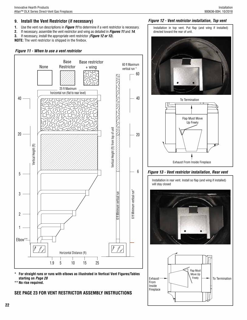
9. Install the Vent Restrictor (if necessary)1. Use the vent run descriptions in Figure 11 to determine if a vent restrictor is necessary.2. If necessary, assemble the vent restrictor and wing as detailed in Figures 11 and 14.3. If necessary, install the appropriate vent restrictor (Figure 12 or 13).NOTE: The vent restrictor is shipped in the firebox.
Figure 11 - When to use a vent restrictor
BaseRestrictor
1
3
20
40
6
20
40
25 ft Maximumhorizontal run (flat to near level)
60 ft Maximumvertical run *
60
1.9 25
Horizontal Distance (ft)
Verti
cal H
eight
(ft)
from
top
of u
nit
Verti
cal H
eight
(ft)
2
5
Elbow**
5 10 15
Base restrictor+ wing
6 ft M
inim
um ve
rtica
l run
*
6 ft M
inim
um ve
rtica
l run
None
*
* For straight runs or runs with elbows as illustrated in Vertical Vent Figures/Tables starting on Page 28
** No rise required.
Figure 12 - Vent restrictor installation, Top vent
Figure 13 - Vent restrictor installation, Rear vent
Installation in top vent. Put flap (and wing if installed) directed toward the rear of unit.
Installation in rear vent. Install so flap (and wing if installed) will stay closed
To Termination
Flap Must Move Up Freely
Exhaust From Inside Fireplace
To Termination
Flap Must Move Up
FreelyExhaust From Inside Fireplace
SEE PAGE 23 FOR VENT RESTRICTOR ASSEMBLY INSTRUCTIONS

Installation 900636-00H, 10/2018
Innovative Hearth ProductsAltair™ DLX Series Direct-Vent Gas Fireplaces
23
10. Connecting the Vent PipeSecure Vent® SV4.5 direct-vent system components are unitized concentric pipe components featuring positive twist lock connections (Figures 15–16). All of the fireplaces covered in this document are fitted with collars having locking inclined channels. The dimpled end of the vent components fit over the fireplace/vent collar to create the positive twist lock connection.1. Align the dimpled end over the collar, adjusting the radial alignment until the four (4) locking dimples are aligned
with the inlet of the four (4) inclined channels on the collar (Figures 15–16). 2. Push the vent component against the collar until it fully engages, then twist the component clockwise, running
the dimples down and along the incline channels until they seat at the end of the channels.NOTE: The unitized design of the Secure Vent® components will engage and seal both the inner and outer vent pipe.
3. If desired, a #6 x 1/2” sheet metal screw can be used at the joint, but is not required as the pipe will securely lock when twisted (Figure 16).
Where required, a telescopic vent section (SV4.5LA) may be used to provide the installer with an option to install in tight and confined spaces, or where the vent run made up of fixed length pieces develops a joint in a undesirable location, or will not build up to the required length. The SV4.5LA Telescopic Vent Section has an effective length of from 1-1/2 to 7” (38 to 178 mm). The SV4.5LA is fitted with a locking inclined channel end (identical to a normal vent section component) and a plain end with three (3) pilot holes. Slip the plain end over the locking channel end of a standard SV4.5 vent component the required distance and secure with three (3) screws.Figure 15 - Connecting vent
componentsFigure 16 - Connected vent
componentsFigure 17 - Elbow Dimensions
Dimple
Locking Incline Channel
Arrow
Appliance Collar or Vent Section
Dimple
Locking Incline
ChannelArrow
SV4.5E90(90° Elbow)
8 1/8 in.(206 mm)
Swivel Joint(360° swivel)
4 13/16 in.(122 mm)
SV4.5E45(45° Elbow)
Swivel Joint(360° swivel)
4-13/16” (122 mm)
8-1/8” (206 mm)
Swivel Joint (360°)
Swivel Joint (360°)
SV4.5E45 (45° elbow)
SV4.5E90 (90° elbow)
Vent Restrictor with Vertical TerminationsWhen vertically terminating the vent system through the roof and using the vent restrictor, install the vent restrictor in the top vent of the fireplace outlet.
If installing more than 6 ft of vertical venting, install the restrictor (Figure 12), from inside or outside the unit, in the inner fireplace collar. The vent restrictor is held in place by friction.
Vent Restrictor with Horizontal TerminationsWhen horizontally terminating a vent system with a vertical vent run up to 4 ft through an exterior wall, no vent restrictor is required.
If installing more than 6 ft of vertical venting, install the restrictor (Figure 13), from inside or outside the unit, in the inner fireplace collar. The vent restrictor is held in place by friction.
Figure 14 - Vent restrictor assembly
Base Restrictor
Base Restrictor+ Wing
Wing
Base
Base
Model Effective LengthSV4.5L6 4-1/2”SV4.5L12 10-1/2”SV4.5L24 22-1/2”
Vent elbows
Vent elbows are available in 90° and 45° configurations. Refer to Figure 17 for the SV4.5E45 and SV4.5E90 elbow dimensions. The elbows feature a twist section to allow them to be routed about the center axis of their initial collar section to align with the required direction of the next vent run element.
1. Rotate the elbow in a clockwise direction (to avoid the possibility of unlocking any of the previously connected vent sections) for proper alignment (Figure 17). See Connecting the vent pipe for more information.
Table 13 - Effective Vent Length
Model Effective LengthSV4.5L36 34-1/2”SV4.5L48 46-1/2”

Installation 900636-00H, 10/2018
Innovative Hearth ProductsAltair™ DLX Series Direct-Vent Gas Fireplaces
24
Vent section length table
Table 14 will assist calculating how many vent sections are needed for the planned vent configuration. When a vent section is engaged with another section, its effective length will be 1-1/2” shorter.
Table 14 - Vent Section LengthNominal Section
Length (in.) 6 12 24 36 48
Tota
l Qty
Nominal Section Length (in.) 6 12 24 36 48
Tota
l QtyNet Section Length
(in.) 4.5 10.5 22.5 34.5 46.5 Net Section Length (in.) 4.5 10.5 22.5 34.5 46.5
Height of VentNumber of Vent Sections
Height of VentNumber of Vent Sections
in. ft in. ft
4.5 0.375 1 0 0 0 0 1 252 21 0 1 0 7 0 8
9 0.75 2 0 0 0 0 2 276 23 0 0 0 8 0 8
10.5 0.875 0 1 0 0 0 1 279 23.25 0 0 0 0 6 6
15 1.25 1 1 0 0 0 2 280.5 23.375 1 0 0 8 0 9
22.5 1.875 0 0 1 0 0 1 289.5 24.125 0 1 0 0 6 7
31.5 2.625 0 3 0 0 0 3 301.5 25.125 0 0 1 0 6 7
34.5 2.875 0 0 0 1 0 1 310.5 25.875 0 0 0 9 0 9
37.5 3.125 1 1 1 0 0 3 325.5 27.125 0 0 0 0 7 7
43.5 3.625 0 2 1 0 0 3 330 27.5 1 0 0 0 7 8
45 3.75 0 0 2 0 0 2 345 28.75 0 0 0 10 0 10
46.5 3.875 0 0 0 0 1 1 349.5 29.125 1 0 0 10 0 11
51 4.25 1 0 0 0 1 2 372 31 0 0 0 0 8 8
55.5 4.625 0 1 2 0 0 3 379.5 31.625 0 0 0 11 0 11
57 4.75 0 0 1 1 0 2 418.5 34.875 0 0 0 0 9 9
67.5 5.625 0 0 3 0 0 3 465 38.75 0 0 0 0 10 10
69 5.75 0 0 0 2 0 2 475.5 39.625 0 1 0 0 10 11
73.5 6.125 1 0 0 2 0 3 480 40 1 1 0 0 10 12
79.5 6.625 0 1 0 2 0 3 492 41 1 0 1 0 10 12
81 6.75 0 0 0 1 1 2 499.5 41.625 0 0 0 1 10 11
91.5 7.625 0 0 2 0 1 3 504 42 1 0 0 1 10 12
93 7.75 0 0 0 0 2 2 511.5 42.625 0 0 0 0 11 11
97.5 8.125 1 0 0 0 2 3 520.5 43.375 0 2 0 1 11 14
103.5 8.625 0 0 0 3 0 3 531 44.25 0 2 2 0 11 15
108 9 1 0 0 3 0 4 538.5 44.875 1 0 0 2 11 14
117 9.75 1 0 5 0 0 6 549 45.75 1 0 2 1 11 15
118.5 9.875 1 1 0 3 0 5 558 46.5 0 0 0 0 12 12
126 10.5 0 0 1 3 0 4 562.5 46.875 1 0 0 0 12 13
130.5 10.875 1 0 1 3 0 5 568.5 47.375 0 1 0 0 12 13
135 11.25 0 0 6 0 0 6 573 47.75 1 1 0 0 12 14
139.5 11.625 0 0 0 0 3 3 580.5 48.375 0 0 1 0 12 13
142.5 11.875 1 0 0 4 0 5 589.5 49.125 0 1 2 2 10 15
144 12 1 0 0 0 3 4 595.5 49.625 1 1 1 0 12 15
154.5 12.875 1 1 0 0 3 5 604.5 50.375 0 0 0 0 13 13
160.5 13.375 0 2 0 0 3 5 615 51.25 0 1 0 0 13 14
172.5 14.375 0 0 0 5 0 5 625.5 52.125 0 2 0 0 13 15
177 14.75 1 0 0 5 0 6 631.5 52.625 1 0 1 0 13 15
186 15.5 0 0 0 0 4 4 637.5 53.125 0 1 1 0 13 15
196.5 16.375 0 1 0 0 4 5 651 54.25 0 0 0 0 14 14
207 17.25 0 0 0 6 0 6 655.5 54.625 1 0 0 0 14 15
211.5 17.625 1 0 0 6 0 7 672 56 0 2 0 0 14 16
217.5 18.125 0 1 0 6 0 7 678 56.5 1 0 1 0 14 16
229.5 19.125 0 0 1 6 0 7 688.5 57.375 1 1 1 0 14 17
232.5 19.375 0 0 0 0 5 5 697.5 58.125 0 0 0 0 15 15
241.5 20.125 0 0 0 7 0 7 702 58.5 1 0 0 0 15 16
246 20.5 1 0 0 7 0 8 712.5 59.375 1 1 0 0 15 17
720 60 0 0 1 0 15 16
Installation 900636-00H, 10/2018
Innovative Hearth ProductsAltair™ DLX Series Direct-Vent Gas Fireplaces
25
Clearance to combustiblesMaintain the minimum clearance to combustibles (e.g., framing, attic, ceiling insulation, etc.).For all vertical runs: • 1” (26 mm) from all sidesNOTE: Attic insulation shield (H3907, see Page 47) must be installed when blown or loose-fill insulation is used, and is required for all attic installations.NOTE: When in top vent mode, No combustible material shall be allowed to contact the rear flue cap/cover.For all horizontal/inclined runs: • 3” (77 mm) from the top• 1” (26 mm) from the sides• 1” (26 mm) from the bottom
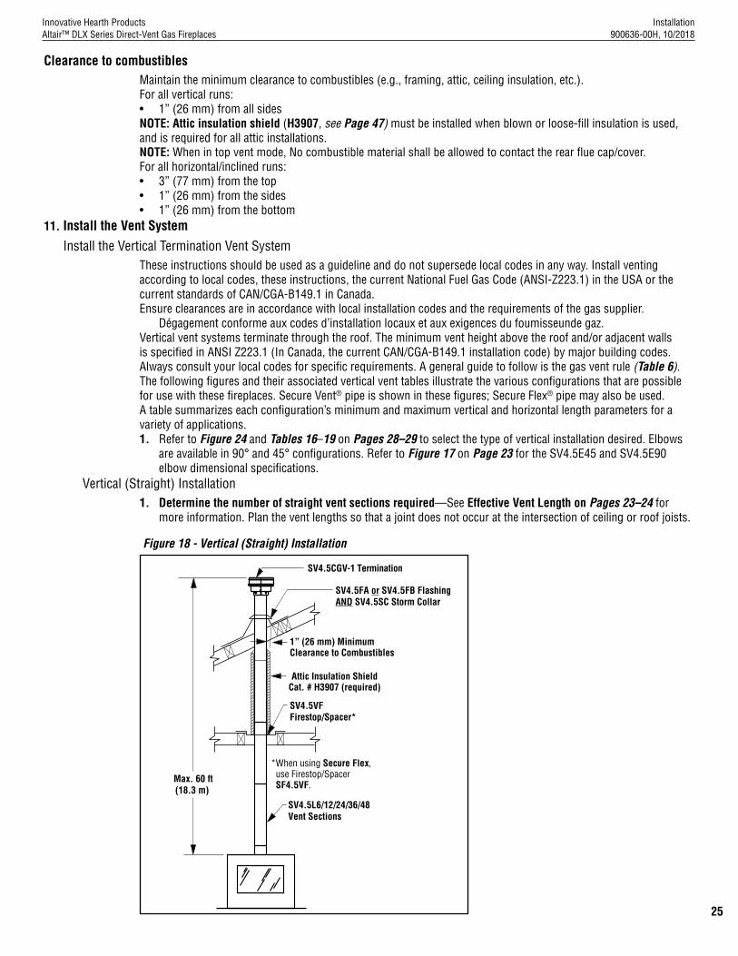
11. Install the Vent SystemInstall the Vertical Termination Vent System
These instructions should be used as a guideline and do not supersede local codes in any way. Install venting according to local codes, these instructions, the current National Fuel Gas Code (ANSI-Z223.1) in the USA or the current standards of CAN/CGA-B149.1 in Canada. Ensure clearances are in accordance with local installation codes and the requirements of the gas supplier.
Dégagement conforme aux codes d’installa tion locaux et aux exigences du foumisseunde gaz.Vertical vent systems terminate through the roof. The minimum vent height above the roof and/or adjacent walls is specified in ANSI Z223.1 (In Canada, the current CAN/CGA-B149.1 installation code) by major building codes. Always consult your local codes for specific requirements. A general guide to follow is the gas vent rule (Table 6).The following figures and their associated vertical vent tables illustrate the various configurations that are possible for use with these fireplaces. Secure Vent® pipe is shown in these figures; Secure Flex® pipe may also be used. A table summarizes each configuration’s minimum and maximum vertical and horizontal length parameters for a variety of applications.1. Refer to Figure 24 and Tables 16–19 on Pages 28–29 to select the type of vertical installation desired. Elbows
are available in 90° and 45° configurations. Refer to Figure 17 on Page 23 for the SV4.5E45 and SV4.5E90 elbow dimensional specifications.
Vertical (Straight) Installation1. Determine the number of straight vent sections required—See Effective Vent Length on Pages 23–24 for
more information. Plan the vent lengths so that a joint does not occur at the intersection of ceiling or roof joists.
Figure 18 - Vertical (Straight) Installation
SV4.5FA or SV4.5FB FlashingAND SV4.5SC Storm Collar
SV4.5VFFirestop/Spacer*
1” (26 mm) MinimumClearance to Combustibles
SV4.5CGV-1 Termination
SV4.5L6/12/24/36/48Vent Sections
*When using Secure Flex, use Firestop/Spacer SF4.5VF.
Max. 60 ft(18.3 m)
Attic Insulation Shield Cat. # H3907 (required)

Installation 900636-00H, 10/2018
Innovative Hearth ProductsAltair™ DLX Series Direct-Vent Gas Fireplaces
26
Vertical (Offset) Installation
1. Analyze the vent route and determine the number of vent sections and elbows required—See Effective Vent Length on Pages 23-24 for more information. Plan the venting so that a joint does not occur in the ceiling or roof joists. Allow for elbows (Figure 17, Page 23). Maintain clearances to combustibles equal to or greater than minimum specified in these instructions (Page 25).
2. Frame the ceiling opening—Use a plumb line from the ceiling above the fireplace to locate the center of the vertical run. Cut and/or frame an opening, 10-1/2 x 10-1/2” (267 x 267 mm) inside dimensions, about this center mark (Figure 19).
Figure 19 - Framing the ceiling opening
minimum 10 1/2 in. (267 mm)
minimum 10 1/2 in. (267 mm)
Roof Framing
Ceiling Framing
Plumb Bob
10-1/2” (267 mm) minimum
10-1/2” (267 mm)minimum
Figure 1 - Rear vent gasket
3. Attach the vent components to the fireplace—See Connecting the vent pipe on Page 23.
4. Attach the vent components to each other—See Connecting the vent pipe on Page 23.
5. Install firestop/spacer at ceiling—When using Secure Vent®, use SV4.5VF firestop/spacer at ceiling joists; when using Secure Flex®, use SF4.5VF firestop/spacer. If there is living space above the ceiling level, the firestop/spacer must be installed on the bottom side of the ceiling. If attic space is above the ceiling, the firestop/spacer must be installed on the top side of the joist. Route the vent sections through the framed opening and secure the firestop/spacer with 8d nails or other appropriate fasteners at each corner.Remember to maintain 1” (26 mm) clearance to combustibles, framing members, and attic or ceiling insulation when running vertical chimney sections. The gap between the vent pipe and a vertical firestop can be sealed with non-combustible caulking.
NOTE: Attic Insulation Shield (H3907) must be installed when blown or loose-fill insulation is used, and is required for all attic installations.
6. Support the vertical vent run sections—Support the vertical portion of the venting system every 8 ft (2.4 m) above the fireplace vent outlet. One method of support is by utilizing field provided support straps (conventional plumber’s tape). Secure the plumber’s tape to the framing members with nails or screws. Loop the tape around the vent, securing the ends of the tape to the framing. If desired, sheet metal screws #6 x 1/2” length may be used to secure the support straps to the vent pipe (Figure 21).
NOTE: Proper venting support is very important.
Figure 21 - Supporting the Vertical Vent Run
Blocking
Support straps (plumber’s tape)
8 ft (2.4 m) maximum
0” (0 mm) to Spacers
Installation 900636-00H, 10/2018
Innovative Hearth ProductsAltair™ DLX Series Direct-Vent Gas Fireplaces
27
7. Change vent direction of horizontal/inclined run—Install the SV4.5E45 and SV4.5E90 elbows in the same manner as the straight vent sections. See Vent elbows on Page 23 for more information.
8. Continue installation of horizontal/inclined sections—Continue with the installation of the straight vent sections in horizontal/inclined run. Install support straps every 5 ft (1.52 m) along horizontal/inclined vent runs using conventional plumber’s tape in a direction away from the fireplace.
Rise per foot run ratios are acceptable all the way to level. For best results, maintain the horizontal/inclined run in a straight (no dips), slightly elevated plane of approximately 1/4” per 1 ft (20 mm per 1 m).
Maintain the required clearances to combustibles (Page 25).
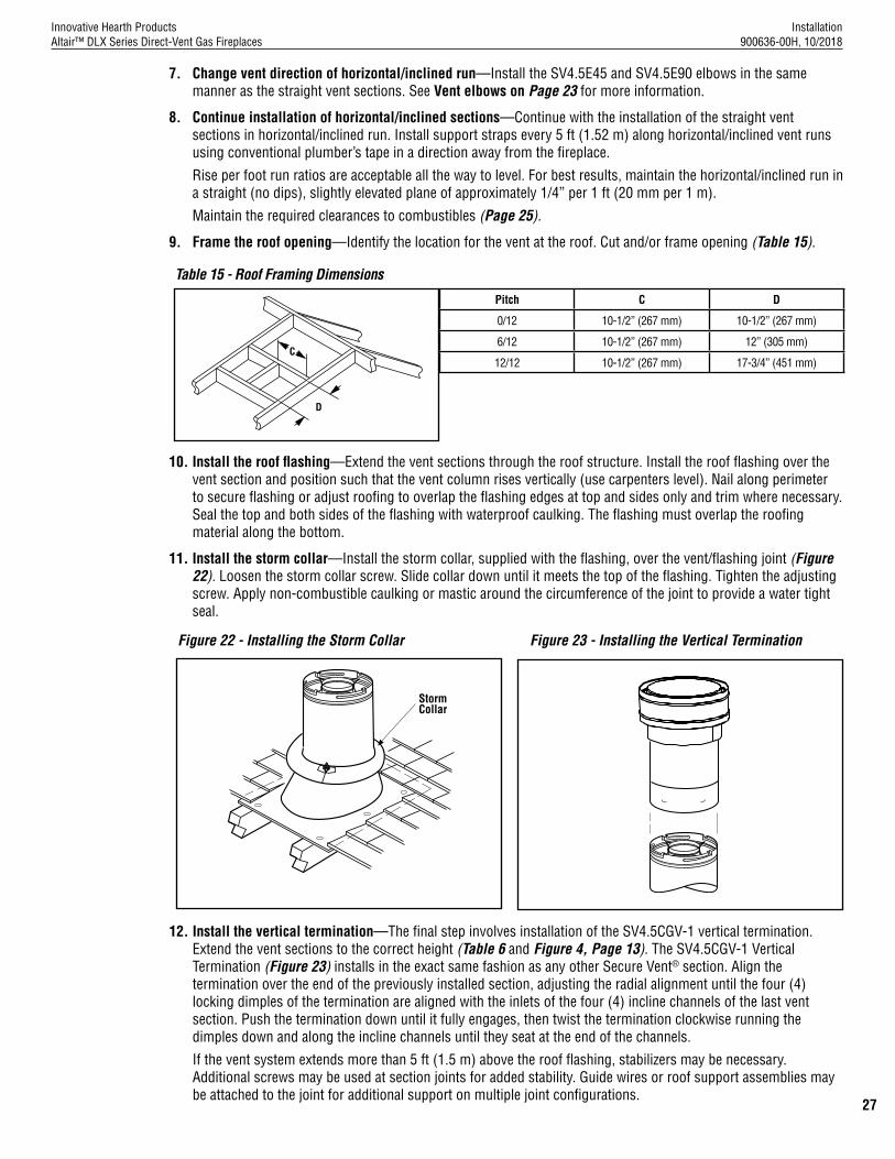
9. Frame the roof opening—Identify the location for the vent at the roof. Cut and/or frame opening (Table 15).
Pitch C D
0/12 10-1/2” (267 mm) 10-1/2” (267 mm)
6/12 10-1/2” (267 mm) 12” (305 mm)
12/12 10-1/2” (267 mm) 17-3/4” (451 mm)C
D
10. Install the roof flashing—Extend the vent sections through the roof structure. Install the roof flashing over the vent section and position such that the vent column rises vertically (use carpenters level). Nail along perimeter to secure flashing or adjust roofing to overlap the flashing edges at top and sides only and trim where necessary. Seal the top and both sides of the flashing with waterproof caulking. The flashing must overlap the roofing material along the bottom.
11. Install the storm collar—Install the storm collar, supplied with the flashing, over the vent/flashing joint (Figure 22). Loosen the storm collar screw. Slide collar down until it meets the top of the flashing. Tighten the adjusting screw. Apply non-combustible caulking or mastic around the circumference of the joint to provide a water tight seal.
Figure 22 - Installing the Storm Collar Figure 23 - Installing the Vertical Termination
StormCollar
12. Install the vertical termination—The final step involves installation of the SV4.5CGV-1 vertical termination. Extend the vent sections to the correct height (Table 6 and Figure 4, Page 13). The SV4.5CGV-1 Vertical Termination (Figure 23) installs in the exact same fashion as any other Secure Vent® section. Align the termination over the end of the previously installed section, adjusting the radial alignment until the four (4) locking dimples of the termination are aligned with the inlets of the four (4) incline channels of the last vent section. Push the termination down until it fully engages, then twist the termination clockwise running the dimples down and along the incline channels until they seat at the end of the channels.
If the vent system extends more than 5 ft (1.5 m) above the roof flashing, stabilizers may be necessary. Additional screws may be used at section joints for added stability. Guide wires or roof support assemblies may be attached to the joint for additional support on multiple joint configurations.
Table 15 - Roof Framing Dimensions

Installation 900636-00H, 10/2018
Innovative Hearth ProductsAltair™ DLX Series Direct-Vent Gas Fireplaces
28
Vertical Vent Figures/Tables
NOTE: Secure Vent® rigid vent pipe is shown in the figures; Secure Flex® flexible vent pipe may also be used.
NOTE: Rise per foot run ratios are acceptable all the way to level. For best results, maintain the horizontal/inclined run in a straight (no dips), slightly elevated plane of approximately 1/4” per 1 ft (20 mm per 1 m).
NOTE: SV4.5VF (Secure Vent), SF4.5VF (Secure Flex) firestop/spacer must be used anytime vent pipe passes through a combustible floor or ceiling. SV4.5HF (Secure Vent), SF4.5HF (Secure Flex)firestop/spacer must be used anytime vent pipe passes through a combustible wall.
NOTE: Two (2) 45° elbows may be used in place of one (1) 90° elbow. The same rise to run ratios, as shown in the venting figures for 90° elbows, must be followed if 45° elbows are used.
WARNING Do NOT join separate sections of concentric flexible vent pipe.
Figure 24 - Top Vent—Straight Table 16 - Rear Vent—One 90° Elbow
Ceiling firestop/
spacer SV4.5VF *
When using Secure Flex®, use ceiling firestop/spacer SF4.5VF.
*
60 ft (18.3 m)maximum
H Maximum V Minimum
feet meters feet meters
5 0.610 1 0.305
10 1.219 2 0.610
15 1.829 3 0.914
20 2.438 4 1.219
Ceiling firestop/spacer SV4.5VF *
When using Secure Flex®, use ceiling firestop/spacer SF4.5VF.
*
H
V
Install the U-shaped vent restrictor in any vent run with more than 6 ft of vertical rise. See Page 22 for more information.
Minimum 6 ft and maximum of 60 ft of vertical venting.
V + H = 60 ft (18.3 m) maximumH = 8 ft (2.4 m) maximumInstall the U-shaped vent restrictor in any vent run with more than 6 ft of vertical rise. See Page 22 for more information.
If 8 ft of (H) horizontal vent run is needed, then 4 ft (straight section) minimum of (V) vertical vent will be required.This table shows a 1 (V) to 5 (H) ratio. For every 1 ft of (V) vertical, you are allowed 2 ft of (H) horizontal run, up to a maximum horizontal run of 8 ft.Minimum 6 ft of vertical venting.
40” MODELS ONLY
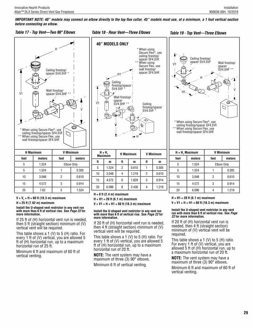
Installation 900636-00H, 10/2018
Innovative Hearth ProductsAltair™ DLX Series Direct-Vent Gas Fireplaces
29
Table 17 - Top Vent—Two 90° Elbows
H Maximum V Minimum
feet meters feet meters
5 1.524 Elbow Only
5 1.524 1 0.305
10 3.048 2 0.610
15 4.572 3 0.914
25 7.62 5 1.524
Ceiling firestop/spacer SV4.5VF *
Wall firestop/spacer SV4.5HF **
When using Secure Flex®, use ceiling firestop/spacer SF4.5VF.When using Secure Flex, use wall firestop/spacer SF4.5HF.
*
**
V1
H
V
V + V1 + H = 60 ft (18.3 m) maximumH = 25 ft (7.62 m) maximumInstall the U-shaped vent restrictor in any vent run with more than 6 ft of vertical rise. See Page 22 for more information.
If 25 ft of (H) horizontal vent run is needed, then 5 ft (straight section) minimum of (V) vertical vent will be required.This table shows a 1 (V) to 5 (H) ratio. For every 1 ft of (V) vertical, you are allowed 5 ft of (H) horizontal run, up to a maximum horizontal run of 25 ft.Minimum 6 ft and maximum of 60 ft of vertical venting.
Table 18 - Rear Vent—Three Elbows
H + H1 Maximum H Maximum V Minimum
ft m ft m ft m
5 1.524 2 0.610 1 0.305
10 3.048 4 1.219 2 0.610
15 4.572 6 1.829 3 0.914
20 6.096 8 2.438 4 1.219
VV
Ceiling firestop/spacer SV4.5VF *
Wall firestop/spacer SV4.5HF **
When using Secure Flex®, use ceiling firestop/spacer SF4.5VF.When using Secure Flex, use wall firestop/spacer SF4.5HF.
*
**
V1
H
Ceiling firestop/spacer SV4.5VF *
H1
H = 8 ft (2.4 m) maximumH + H1 = 20 ft (6.1 m) maximumV + V1 + H + H1 = 60 ft (18.3 m) maximum
Install the U-shaped vent restrictor in any vent run with more than 6 ft of vertical rise. See Page 22 for more information.
If 20 ft of (H) horizontal vent run is needed, then 4 ft (straight section) minimum of (V) vertical vent will be required.This table shows a 1 (V) to 5 (H) ratio. For every 1 ft of (V) vertical, you are allowed 5 ft of (H) horizontal run, up to a maximum horizontal run of 20 ft.NOTE: The vent system may have a maximum of three (3) 90° elbows.Minimum 6 ft of vertical venting.
Table 19 - Top Vent—Three Elbows
H + H1 Maximum V Minimum
feet meters feet meters
5 1.524 Elbow Only
5 1.524 1 0.305
10 3.048 2 0.610
15 4.572 3 0.914
20 6.096 4 1.219
Ceiling firestop/spacer SV4.5VF *
Wall firestop/spacer SV4.5HF **
When using Secure Flex®, use ceiling firestop/spacer SF4.5VF.When using Secure Flex, use wall firestop/spacer SF4.5HF.
*
**
V1
H
VH1
H + H1 = 20 ft (6.1 m) maximumV + V1 + H + H1 = 60 ft (18.3 m) maximum
Install the U-shaped vent restrictor in any vent run with more than 6 ft of vertical rise. See Page 22 for more information.
If 20 ft of (H) horizontal vent run is needed, then 4 ft (straight section) minimum of (V) vertical vent will be required.This table shows a 1 (V) to 5 (H) ratio. For every 1 ft of (V) vertical, you are allowed 5 ft of (H) horizontal run, up to a maximum horizontal run of 20 ft.NOTE: The vent system may have a maximum of three (3) 90° elbows.Minimum 6 ft and maximum of 60 ft of vertical venting.
40” MODELS ONLY
IMPORTANT NOTE: 40” models may connect an elbow directly to the top flue collar. 45” models must use, at a minimum, a 1 foot vertical section before connecting an elbow.

Installation 900636-00H, 10/2018
Innovative Hearth ProductsAltair™ DLX Series Direct-Vent Gas Fireplaces
30
Install the Horizontal Termination Vent System
These instructions should be used as a guideline and do not supersede local codes in any way. Install venting according to local codes, these instructions, the current National Fuel Gas Code (ANSI-Z223.1) in the USA or the current standards of CAN/CGA-B149.1 in Canada. Ensure clearances are in accordance with local installation codes and the requirements of the gas supplier.
Dégagement conforme aux codes d’installa tion locaux et aux exigences du foumisseunde gaz.Horizontal vent systems terminate through an outside wall. Building Codes limit or prohibit terminating in specific areas (Table 7, Page 14).The following figures and their associated horizontal vent tables illustrate the various configurations that are possible for use with these fireplaces. Secure Vent® pipe is shown in these figures; Secure Flex® pipe may also be used. A table summarizes each configuration’s minimum and maximum vertical and horizontal length parameters for a variety of applications. For more information on connecting the vent pipe, see Page 23.Assure that adequate space between the bottom of the horizontal run and the attic is provided so that blown in insulation does not contact the vent.
Figure 25 - Typical Horizontal Vent Installation
Support bracket spacingevery 5 ft (1.52 m)
Firestop/Spacer
Vertical Vent
Fireplace
VerticalRise
Ceiling
SV4.5E90Elbow
SupportBrackets
BuildingSupportFraming
Horizontal / Inclined Run
40” Models = Elbow only allowed45” Models = Requires 1 ft. section before elbow
Termination
Termination
ExteriorWall
SV4.5L6/12/24/36/48Vent Sections
1. Analyze the vent route and determine the number of vent sections and elbows required—See Effective Vent Length on Pages 23–24 for more information. Plan the venting so that a joint does not occur in the ceiling or roof joists. Allow for elbows (Figure 17, Page 23). Maintain clearances to combustibles equal to or greater than minimum specified in these instructions (Page 25).
2. Frame the exterior wall opening—Locate the center of the vent outlet on the exterior wall (Table 10, Page 18). Cut and/or frame an opening, 10-1/2 x 12-1/8” (267 x 308 mm) inside dimensions, about this center.
3. Frame the ceiling opening—If the vertical route is to penetrate a ceiling, use plumb line to locate the center above the fireplace. Cut and/or frame an opening, 10-1/2 x 10-1/2” (267 x 267 mm) inside dimensions, about this center (Figure 19, Page 26).
4. Attach the vent components to the fireplace—See Connecting the vent pipe on Page 23.
5. Attach the vent components to each other—See Connecting the vent pipe on Page 23.

Installation 900636-00H, 10/2018
Innovative Hearth ProductsAltair™ DLX Series Direct-Vent Gas Fireplaces
31
6. Install the firestop/spacer at the ceiling—When using Secure Vent®, use SV4.5VF firestop/spacer at ceiling joists; when using Secure Flex®, use SF4.5VF firestop/spacer. If there is living space above the ceiling level, the firestop/ spacer must be installed on the bottom side of the ceiling. If attic space is above the ceiling, the firestop/spacer must be installed on the top side of the joist. Route the vent sections through the framed opening and secure the firestop/spacer with 8d nails or other appropriate fasteners at each corner.Maintain 1” (26 mm) clearance to combustibles, framing members, and attic or ceiling insulation when running vertical chimney sections.
7. Support the vertical run sections—On the vertical run, support the venting system every 8 ft (2.4 m) above the fireplace vent outlet with field provided support straps (Plumber’s tape). Attach the straps to the vent pipe and secure to the framing members with nails or screws (Figure 21, Page 26).
8. Change vent direction—At transition from or to a horizontal/inclined run, install SV4.5E45 or SV4.5E90 elbows in the same manner as the straight vent sections. The elbows feature a twist section to allow them to be routed about the center axis of their initial collar section to align with the required direction of the next vent run element. Twist elbow sections in a clockwise direction only so as to avoid the possibility of unlocking any of the previously connected vent sections (Figure 17).
9. Continue installation of horizontal/inclined sections—Continue with the installation of the straight vent sections in horizontal/inclined run. Install support straps every 5 ft. (1.52 m) along horizontal/inclined vent runs using conventional plumber’s tape (Figure 25). Maintain the horizontal/inclined run in a straight (no dips), slightly elevated plane. The recommended incline is approximately 1/4” per 1 ft (20 mm per 1 m) horizontal, in a direction away from the fireplace. Smaller rise per foot run ratios are acceptable all the way to at or near level. Use a carpenter’s level to measure from a constant surface and adjust the support straps as necessary. Maintain the required clearances to combustibles (Page 30).
10. Assemble the vent run to the exterior wall—If not previously measured, locate the center of the vent at the exterior wall. Prepare the opening. Assemble the vent system until the terminus of the last section is within 7” (178 mm) to 11-1/4” (286 mm) inboard of the exterior surface to which the SV4.5HT termination is to be attached (Figure 26). If the terminus of the last section is not within this distance, use the telescopic vent section SV4.5LA, as the last vent section. Table 20 lists the additional venting components needed (in addition to the termination and adaptor) for a range of wall thicknesses.
11. Attach the termination adaptor—Attach the adaptor (SV4.5RCH, provided with the termination) to the vent section or telescoping vent section, elbow or fireplace collar (Figure 26).
12. Install the firestop/spacer at the exterior wall—When using the square termination, install SV4.5HF (Secure Vent), SF4.5HF (Secure Flex) Firestop/Spacer over the opening at the exterior side of the framing, long side up, with the 3” spacer clearance at the top (Figure 26) and nail into place.
NOTE: The firestop/spacer may also be installed over the opening at the interior side of the framing.
13. Install the termination (SV4.5HT-2)—From outside the exterior wall, slide the collars of the termination onto the adaptor (the outer over the outer and the inner inside the inner) until the termination seats against the exterior wall surface to which it will be attached. Orient the housing of the termination with the arrow pointed upwards. Secure the termination to the exterior wall. The horizontal termination must not be recessed into the exterior wall or siding by more than the 1-1/4” (32 mm) (Figure 27).
NOTE: If the venting exits the building below grade, or close to grade, see Installation Accessories on Page 47 for available snorkel terminations. The termination must be above grade and above the expected level of snow accumulation.
NOTE: The vent termination is hot while in operation and for a period of time following the use of the fireplace. To prevent contact with hot surfaces, use a horizontal termination guard; available for purchase at your local dealer.
The horizontal terminations have been designed to perform in a wide range of weather conditions. Our terminations meet or exceed industry standards.
When selecting the locations of your horizontal terminations, do not place the termination where water from eaves and adjoining rooflines may create a heavy flow of cascading water onto the termination cap. If the cap must be placed where the possibility of cascading water exists, it is the responsibility of the builder to direct the water away from the termination cap by using gutters or other means.
Take care to carefully follow the installation instructions for the termination, including the use of silicone caulking where required.

Installation 900636-00H, 10/2018
Innovative Hearth ProductsAltair™ DLX Series Direct-Vent Gas Fireplaces
32
Firestop/Spacer (SV4.5HF) shownon the exterior side of the wall. It
may also be installed on theinterior side.
TypicalTermination
Shown
7”(178)
5-1/8”(130 mm)
12-1/8”(308 mm)
Note: Centerline of Vent Piping isNOT the Same as the Centerline of
the Frame Opening.
6” to 48” Vent Section,Telescopic vent section,
Elbow or Appliance Collar Base of Appliance
3”(77 mm)
1”(26 mm)Adaptor
SV4.5RCH
10-1/2”(267 mm)
*
To help minimize water infiltration it is recommended that the Fire-stop/ Spacer (SV4.5HF) be installed on the exterior side of the wall.
*Recommended IHP termination kit: H1968. **With termination kit only, 6 to 9-1/4”
**
See Table 10 for the minimum distance to the base of the fireplace.
Figure 26 - Installing the Horizontal Termination
NOTE: To help minimize water infiltration install the firestop/spacer (SV4.5HF) on the exterior side of the wall. The firestop may be caulked with mill base caulk (such as 10K81) or high-temperature silicone.
Figure 27 - Venting Connection and Exterior Wall Recessing of the Horizontal Termination H1968
* Use silicone caulking to seal the top and sides of the termination, up to the under-layment, stucco, or masonry wall surface.
AdaptorSV4.5RCH
**For thicknesses greater than 9-1/4" (235mm), see Table 20.
SV4.5HT-2Square Termination
Maximum Wall Thickness 9-1/4" (235 mm)**
Exterior Surface of Siding
Exterior Surface ofFraming
6" to 9-1/4"(152 to 235 mm)**
1-1/4" Maximum Recess of the Square Termination into Exterior Finishing Material
SV4.5HT-2Square Termination
*Caulk
*Caulk
Stucco
Siding
Interior Surface ofFinished Wall
Last Vent Section. Use Telescopic Vent Section (SV4.5LA), If Necessary
Maximum Extent of Vent Run Sections Relative to Exterior Surface of Framing

Installation 900636-00H, 10/2018
Innovative Hearth ProductsAltair™ DLX Series Direct-Vent Gas Fireplaces
33
Table 20 - Venting Components Required for Various Exterior Wall Thicknesses, when using Typical Termination Kits
Vent Components Required Exterior Wall Thickness
Termination Kit Only 6 to 9-1/4” (152 to 235 mm)
Termination Kit and 6” Vent Section (SV4.5L6) 10-3/4 to 14” (273 to 356 mm)
Termination Kit and 12” Vent Section (SV4.5L12) 16-3/4 to 20” (426 to 508 mm)
Termination Kit and Telescopic Section (SV4.5LA)and 6” vent section (SV4.5L6) 11-3/4 to 20” (299 to 508 mm)
Horizontal Vent Figures/Tables
NOTE: Secure Vent® rigid vent pipe and terminal are shown in the figures. Secure Flex® flexible vent pipe and terminal may also be used.
NOTE: Two (2) 45° elbows may be used in place of one (1) 90° elbow. The same rise to run ratios, as shown in the venting figures for 90° elbows, must be followed if 45° elbows are used.
NOTE: Maintain the horizontal/inclined run in a straight (no dips), slightly elevated plane. The recommended incline is approximately 1/4” per 1 ft (20 mm per 1 m) horizontal, in a direction away from the fireplace. Smaller rise per foot run ratios are acceptable all the way to at or near level. Use a carpenter’s level to measure from a constant surface and adjust the support straps as necessary.
NOTE: SV4.5VF (Secure Vent), SF4.5VF (Secure Flex) firestop/spacer must be used any time vent pipe passes through a combustible floor or ceiling. SV4.5HF (Secure Vent), SF4.5HF (Secure Flex) firestop/spacer must be used any time vent pipe passes through a combustible wall.
WARNING Do not join separate sections of concentric flexible vent together.
Table 21 - Rear Vent—No Elbows
See Table 20 as an aid in venting component selection for a particular range of exterior wall thicknesses.
NOTE: “H” is horizontal distance from rear of unit to outer wall surface.
H
H = 28 in. (711 mm) Maximum
**When using Secure Flex, use Wall Firestop/Spacer SF4.5HF.
When using Secure Flex®, use wall firestop/spacer SF4.5HF, and install venting with a minimum of 12” rise. (Page 47).
H = 21” (533 mm) maximum
27-1/2” (699 mm) to outside
of termination
Table 22 - Top Vent—One 90° Elbow, Elbow Connection at Fireplace
H Maximum V Minimum
feet meters feet meters
3 0.91 Elbow only
Install the U-shaped vent restrictor in any vent run with more than 4 ft of vertical rise. See Page 22 for more information.See Table 20 as an aid in venting component selection for a particular range of exterior wall thicknesses.NOTE: Only in top vent where elbow is connected at fireplace collar is it allowed to count elbow as 1 ft. vertical (V) rise. Wall
firestop/spacer SV4.5HF *
When using Secure Flex®, use wall firestop/spacer SF4.5HF.
*
H
V
40” MODELS ONLY
40” MODELS ONLY

Installation 900636-00H, 10/2018
Innovative Hearth ProductsAltair™ DLX Series Direct-Vent Gas Fireplaces
34
Table 23 - Top Vent—One 90° Elbow, Elbow Connection NOT at Fireplace
H Maximum V Minimum
feet meters feet meters
5 1.524 1 0.305
10 3.048 2 0.610
15 4.572 3 0.914
25 7.62 5 1.524
Install the U-shaped vent restrictor in any vent run with more than 4 ft of vertical rise. See Page 22 for more information.See Table 20 as an aid in venting component selection for a particular range of exterior wall thicknesses.If 25 ft of (H) horizontal vent run is needed, then 5 ft minimum of (V) vertical vent will be required.This table shows a 1 (V) to 5 (H) ratio. For every 1 ft of (V) vertical, you are allowed 5 ft of (H) horizontal run, up to a maximum horizontal run of 25 ft (7.62 m).
H
V
When using Secure Flex,use Firestop/Spacer
SF4.5VF.
CeilingFirestop/Spacer
(SV4.5VF)
When using Secure Flex,use Firestop/Spacer
SF4.5HF.
Wall Firestop/Spacer(SV4.5HF)
Min. OneFoot VentSection
Required
When using Secure Flex®, use ceiling firestop/spacer SF4.5VF.When using Secure Flex, use wall firestop/spacer SF4.5HF.
*
**
Wall firestop/spacer SV4.5HF **
Ceiling firestop/
spacer SV4.5VF *
H
V
Table 24 - Rear Vent—Two 90° Elbows
H + H1 Maximum H Maximum V Minimum
feet meters feet meters feet meters
5 1.524 2 0.610 1 0.305
10 3.048 4 1.219 2 0.610
15 4.572 6 1.829 3 0.914
25 7.62 10 3.048 5 1.524
V + H + H1 = 60 ft (18.288 m) maximumH = 8 ft (2.438 m) maximumH + H1 = 25 ft (7.62 m) maximumInstall the U-shaped vent restrictor in any vent run with more than 4 ft of vertical rise. See Page 22 for more information.See Table 20 as an aid in venting component selection for a particular range of exterior wall thicknesses.If 25 ft of (H) horizontal vent run is needed, then 5 ft minimum of (V) vertical vent will be required.This table shows a 1 (V) to 5 (H) ratio. For every 1 ft of (V) vertical, you are allowed 5 ft of (H) horizontal run, up to a maximum horizontal run of 25 ft (7.62 m).
*When using Secure Flex , use Ceiling Firestop/Spacer SF4.5VF.**When using Secure Flex, use Wall Firestop/Spacer SF4.5HF.
Wall Firestop/Spacer SV4.5HF**
CeilingFirestop/SpacerSV4.5VF*
®
V
HH1
When using Secure Flex®, use ceiling firestop/spacer SF4.5VF.When using Secure Flex, use wall firestop/spacer SF4.5HF.
*
**
Wall firestop/spacer
SV4.5HF **
Ceiling firestop/spacer SV4.5VF *
H
V
H1
Table 25 - Top Vent—Two 90° Elbows
H + H1 Maximum V Minimum
feet meters feet meters
3 0.91 Elbow only
5 1.524 1 0.305
10 3.048 2 0.610
15 4.572 3 0.914
25 7.62 5 1.524
V + H + H1 = 60 ft (18.288 m) maximumH + H1 = 25 ft (7.62 m) maximum
Install the U-shaped vent restrictor in any vent run with more than 4 ft of vertical rise. See Page 22 for more information.See Table 20 as an aid in venting component selection for a particular range of exterior wall thicknesses.If 25 ft of (H) horizontal vent run is needed, then 5 ft minimum of (V) vertical vent will be required.This table shows a 1 (V) to 5 (H) ratio. For every 1 ft of (V) vertical, you are allowed 5 ft of (H) horizontal run, up to a maximum horizontal run of 25 ft (7.62 m).
V
H
H1
�Wall Firestop/Spacer(SV4.5HF)
�When using Secure Flex,use Firestop/Spacer
SF4.5HF.
�CeilingFirestop/Spacer
(SV4.5VF)
�Note - When usingSecure FlexTM, use
Firestop/Spacer SF4.5VF.
�WallFirestop/Spacer
(SV4.5HF)
Min. One Foot VentSection Required
When using Secure Flex®, use ceiling firestop/spacer SF4.5VF.When using Secure Flex, use wall firestop/spacer SF4.5HF.
*
**
Wall firestop/spacer
SV4.5HF **Ceiling firestop/
spacer SV4.5VF *
H
VH1
Wall firestop/spacer SV4.5HF **
40” MODELS ONLY

Installation 900636-00H, 10/2018
Innovative Hearth ProductsAltair™ DLX Series Direct-Vent Gas Fireplaces
35
Table 26 - Rear Vent—Three 90° Elbows
H + H1 + H2 Maximum H Maximum V Minimum
feet meters feet meters feet meters
5 1.524 2 0.610 1 0.305
10 3.048 4 1.219 2 0.610
15 4.572 6 1.829 3 0.914
20 6.096 8 2.438 4 1.219
V + H + H1 + H2 = 60 ft (18.288 m) maximumH = 8 ft (2.438 m) maximumH + H1 + H2 = 25 ft (7.62 m) maximum
Install the U-shaped vent restrictor in any vent run with more than 4 ft of vertical rise. See Page 22 for more information.See Table 20 as an aid in venting component selection for a particular range of exterior wall thicknesses.If 20 ft of (H) horizontal vent run is needed, then 4 ft minimum of (V) vertical vent will be required.This table shows a 1 (V) to 5 (H) ratio. For every 1 ft of (V) vertical, you are allowed 5 ft of (H) horizontal run, up to a maximum horizontal run of 20 ft (6.096 m).
V
Wall Firestop/Spacer SV4.5HF**
CeilingFirestop/Spacer
SV4.5VF*
H
1
H
H
2
When using Secure Flex®, use ceiling firestop/spacer SF4.5VF.When using Secure Flex, use wall firestop/spacer SF4.5HF.
*
**
Wall firestop/spacer SV4.5HF **
Ceiling firestop/spacer
SV4.5VF *
H
V
H1
H2
Table 27 - Top Vent—Three 90° Elbows
H Maximum V Minimum
feet meters feet meters
5 1.524 Elbow only
5 1.524 1 0.305
10 3.048 2 0.610
15 4.572 3 0.914
20 6.096 4 1.219
H + H1 = 25 ft (7.62 m) maximumV + V1 + H + H1 = 60 ft (18.288 m) maximum
Install the U-shaped vent restrictor in any vent run with more than 4 ft of vertical rise. See Page 22 for more information.See Table 20 as an aid in venting component selection for a particular range of exterior wall thicknesses.If 20 ft of (H) horizontal vent run is needed, then 4 ft minimum of (V) vertical vent will be required.This table shows a 1 (V) to 5 (H) ratio. For every 1 ft of (V) vertical, you are allowed 5 ft of (H) horizontal run, up to a maximum horizontal run of 20 ft (6.096 m).
*When using Secure Flex, use Ceiling Firestop/Spacer SF4.5VF.**When using Secure Flex, use Wall Firestop/Spacer SF4.5HF.
CeilingFirestop/SpacerSV4.5VF*
Wall Firestop/Spacer SV4.5HF**
V
H
V1
Wall Firestop/Spacer SV4.5HF**
1H
Wall firestop/spacer SV4.5HF **
When using Secure Flex®, use ceiling firestop/spacer SF4.5VF.When using Secure Flex, use wall firestop/spacer SF4.5HF.
*
**
Wall firestop/spacer SV4.5HF **
Ceiling firestop/spacer SV4.5VF *
H
V
H1
V1
40” MODELS ONLY

Installation 900636-00H, 10/2018
Innovative Hearth ProductsAltair™ DLX Series Direct-Vent Gas Fireplaces
36
Vertical or Horizontal Venting Using Secure Flex® Kits and Components
When Secure Flex® kits are used in a rear flue, horizontal termination installation, at least 1 ft of vertical rise is required.Secure Flex® venting kits and components may be used in any other vent installation where rigid Secure Vent® (SV4.5) direct-vent components can be used. All restrictions, clearances and allowances pertaining to rigid vent also apply to flexible vent. Do NOT modify Secure Flex kits . Also, do NOT join separate sections of flex vent together. Secure Flex kits can be installed on the end of a Secure Vent (SV4.5) rigid vent run, provided that doing so does not violate any of the venting length, height, routing, horizontal to vertical ratio requirements, or clearance considerations detailed in this manual. When combined, a rigid vent should not be installed between two flexible vents.Secure Flex kits come with an included adaptor that can be installed on the fireplace collar or the inclined channel end of the last Secure Vent (SV4.5) vent section in a rigid system in the exact same fashion as any other Secure Vent section. Align the dimpled end of the adaptor over the previously installed section or fireplace collar, adjusting the radial alignment until the four locking dimples of the adaptor are aligned with the inlets of the four incline channels of the last vent section or collar. Push on the adaptor until it is fully engaged, then twist the adaptor clockwise running the dimples down and along the incline channels until they seat at the end of the channels.
Figure 28 - Flexible Vent Adaptor Figure 29 - Flexible Vent
1. Install the Inner Flex Pipe. a. Install the small gear clamp loosely around the inner flexible vent, then push it back out of the way.b. Apply a bead of Mill-Pac Black (700 °F) high temperature sealant (P/N 10K81) to the inner adaptor collar,
approximately 1/2” from the end.c. Pull and extend the inner flexible vent. d. Slide the inner flex vent over the adaptor collar at least 1-3/4”.NOTE: Ensure the flex vent is free from damage or tears. e. Slide the gear clamp down and tighten it fully to secure the flexible vent to the adaptor inner collar
approximately 3/4” from the end of the flex.f. Install three (3) sheet metal screws 120° apart through the flexible vent and into the adaptor collar just below
the gear clamp to provide additional security to the connection.2. Install the outer Flex Pipe.
a. Install the large gear clamp loosely around the outer flexible vent pipe, then push it back out of the way.b. Apply a bead of Mill-Pac Black (700 °F) high temperature sealant (P/N 10K81) to the outer adaptor collar.
Cover to the grooves of the collar that extend approximately 1” from the end and to the flat surface, approximately 1 3/8” from the end.
c. Pull and extend the outer flexible vent.d. Slide the outer flexible vent over the adaptor collar. Ensure the flexible vent completely engages the adaptor collar
1-3/4” from the end, and that it is free from damage or tears.e. Slide the gear clamp down and tighten it fully to secure the flexible vent to the adaptor outer collar
approximately 3/4” from the end of the flexible vent.
Flexible vent section
5” (127 mm) radius minimum
Shown here: 36” Flex Connector Kit (H7748)
36” of flex with two adaptors for mating two rigid sections of vent
together.
Apply ONLY MIL-PAC BLACK HIGH TEMPERATURE
SEALANT (P/N 10K81) to the outside surface of both
collars of the adaptor (fill the grooves of the outer collar to
be covered by the flexible pipe) and slide the flexible vent over
the inner and outer adaptor collars
NOTE: Outer vent pipe is pulled away to show inner vent pipe details.
Adaptor (SV4.5RF)
Attach adaptor to vent collar or Secure Vent sections
1-3/4” (44 mm) flexible vent and adaptor inner collar overlap
Securing screws in three (3) places through perforation and into the pipe
Gear clamps
Flexible vent
1-3/4” (44 mm) flexible vent and adaptor outer
collar overlap
Securing screws in three (3) places through perforation and into the pipe

Installation 900636-00H, 10/2018
Innovative Hearth ProductsAltair™ DLX Series Direct-Vent Gas Fireplaces
37
f. Install three (3) sheet metal screws 120° apart through the flexible vent and into the adaptor collar just below the gear clamp to provide additional security to the connection.
3. Route the flexible vent.
NOTE: Ensure that the flexible vent is properly routed to provide the required clearance. Do NOT allow the flexible vent to bend in a radius tighter than 5” (127 mm) (Figure 29). Place the internal flexible vent spacers evenly and avoid kinking the inner vent. Support horizontal sections of flexible vent with metal straps at 2 ft (0.61 m) intervals.
4. Install firestop/spacers at ceiling and wall penetrations. • SF4.5VF firestop/spacer for ceilings • SF4.5HF firestop/spacer for walls
NOTE: See the appropriate sections and figures shown throughout the venting section for installation requirements.
5. Attach the flexible vent to the termination.
NOTE: Secure Flex® components can be purchased separately and attached to bulk lengths of Secure Flex flexible vent cut to size at the job site. Attach the flexible vent to the Secure Flex terminations as it was attached to the adaptor (Figure 28).
NOTE: Attach Secure Flex vent to Secure Flex terminations only. Do NOT substitute Secure Vent® terminations or Secure Vent adaptor for Secure Flex components. Secure Flex termination and adaptor collars are a different circumference than Secure Vent collars. Secure Flex vent has an longer center tube to improve ease-of-installation.
12. Complete the Field Wiring
CAUTION The ground supply lead must be connected to the wire attached to the green ground screw located on the outlet box (see wiring diagrams). Failure to do so will result in a potential safety hazard. The appliance must be electrically grounded in accordance with local codes or, in the absence of local codes, the National Electrical Code, ANSI/NFPA 70—latest edition (in Canada, the current CSA C22.1 Canadian Electrical Code).
CAUTION Label all wires prior to disconnection when servicing controls. Wiring errors can cause improper and dangerous operation.
ATTENTION Au moment de l’entretien des commandes, étiquetez tous les fils avant de les débrancher. Des erreurs de cáblage peuvent entraîner un fonctionnement inadéquat et dangereux.
Verify proper operation after servicing.S’assurer que l’appareil fonctionne adéquatement une fois l’entretien terminé.
The gas valve is set in place and pre-wired at the factory.
Electronic Wiring
One of the following optional controls must be used:
• Unit-Mounted ON/OFF Control Switch• Remote Control.
See the Operation section on Page 50 for more details.
NOTE: Electronic models must be connected to the main power supply.
1. Route a 3-wire, 120 Vac, 60 Hz, 1 ph power supply to the fireplace junction box.
2. Remove the electrical inlet cover plate from the side of the unit by removing the plate’s securing screws (Table 12).
3. If unit is not supplied with a strain relief, remove the cover plate knockout. Then, feed the power supply wire through the knockout opening and into the unit junction box.
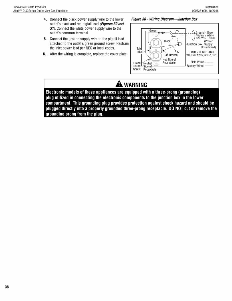
Installation 900636-00H, 10/2018
Innovative Hearth ProductsAltair™ DLX Series Direct-Vent Gas Fireplaces
38
4. Connect the black power supply wire to the lower outlet’s black and red pigtail lead (Figures 30 and 31). Connect the white power supply wire to the outlet’s common terminal.
5. Connect the ground supply wire to the pigtail lead attached to the outlet’s green ground screw. Restrain the inlet power lead per NEC or local codes.
6. After the wiring is complete, replace the cover plate.
WARNING Electronic models of these appliances are equipped with a three-prong (grounding) plug utilized in connecting the electronic components to the junction box in the lower compartment. This grounding plug provides protection against shock hazard and should be plugged directly into a properly grounded three-prong receptacle. DO NOT cut or remove the grounding prong from the plug.
Figure 30 - Wiring Diagram—Junction Box
Green Ground Screw
Red
Black
Hot Side of Receptacle
Tab Broken
Tab Intact
GreenWhite
Neutral Side of Receptacle
120 VAC - BlackNeutral - WhiteGround - Green
J-BOX / RECEPTACLE WIRING 120V, 60HZ, 1PH
Junction Box
Field WiredFactory Wired
(Power Supply
Unswitched)
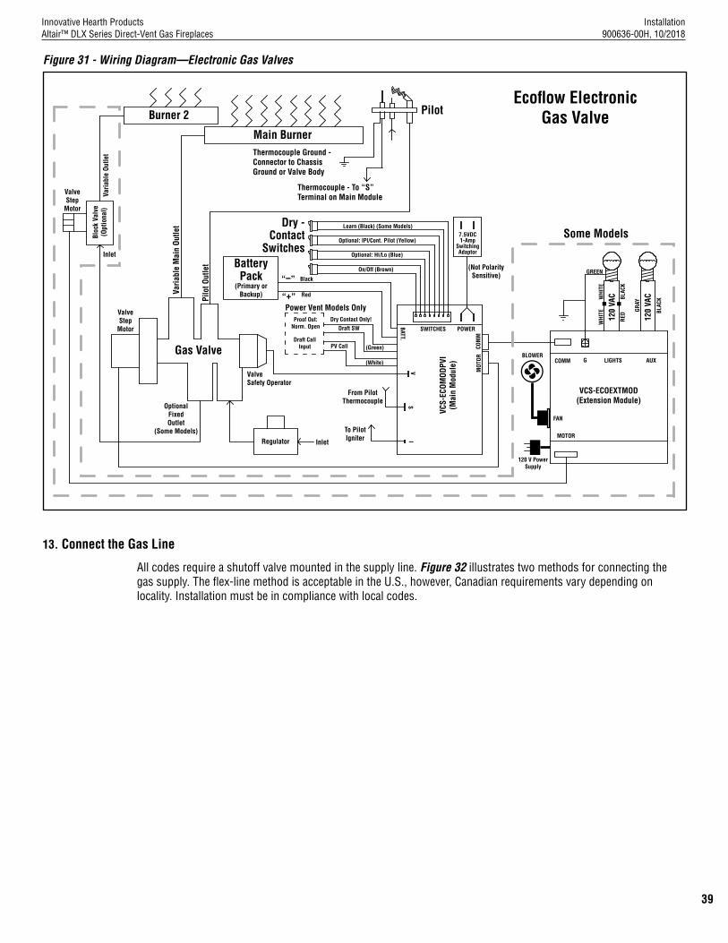
Installation 900636-00H, 10/2018
Innovative Hearth ProductsAltair™ DLX Series Direct-Vent Gas Fireplaces
39
Burner 2 Pilot
Thermocouple Ground -Connector to ChassisGround or Valve Body
(Not PolaritySensitive)
VCS-ECOEXTMOD(Extension Module)
VCS-
ECOM
ODPV
I(M
ain
Mod
ule)
On/Off (Brown)
Optional: Hi/Lo (Blue)
Optional: IPI/Cont. Pilot (Yellow)
Learn (Black) (Some Models)
ValveSafety Operator
OptionalFixedOutlet
(Some Models)
MOT
ORCO
MM
120
VAC
120
VAC
POWER
AUXLIGHTS
WHI
TE
RED
WHI
TE
BLAC
K
GRAY
BLAC
K
MOTOR
FAN
GCOMM
SWITCHES
Power Vent Models Only
(Green)Draft Call
Input
BATT.
VS
I
(White)
PV Call
Proof Out: Norm. Open Draft SW
Dry Contact Only!
Varia
ble
Mai
n Ou
tlet
Pilo
t Out
let
Thermocouple - To “S” Terminal on Main Module
Main Burner
Battery Pack
(Primary or Backup)
Dry -Contact
Switches7.5VDC 1-Amp
Switching Adaptor
“–”
“+”
To PilotIgniter
From PilotThermocouple
Regulator Inlet
Gas Valve
ValveStep
Motor
ValveStep
Motor
Varia
ble
Outle
tBl
ock
Valv
e (O
ptio
nal)
Inlet
Some Models
GREEN
BLOWER
120 V PowerSupply
Black
Red
Figure 31 - Wiring Diagram—Electronic Gas Valves
Ecoflow ElectronicGas Valve
13. Connect the Gas Line
All codes require a shutoff valve mounted in the supply line. Figure 32 illustrates two methods for connecting the gas supply. The flex-line method is acceptable in the U.S., however, Canadian requirements vary depending on locality. Installation must be in compliance with local codes.

Installation 900636-00H, 10/2018
Innovative Hearth ProductsAltair™ DLX Series Direct-Vent Gas Fireplaces
40
NOTE: A sediment trap is recommended in the gas piping within the home to prevent moisture and debris in the line from damaging the valve.
NOTE: Secure all joints tightly using appropriate tools and sealing compounds (ensure propane resistant compounds are used in propane applications). Seal around the gas line to prevent cold air leakage. Gas line holes and other openings can be caulked or stuffed with unfaced fiberglass insulation.Figure 32 - Gas Line Connection
(Optional) flexible gas line connector
Gas valve
3/8” Nipple3/8” Union
3/8” Close nipple3/8” Shutoff valve
3/8 NPT x 3/8” Flare fitting
1/2 x 3/8” Flare shutoff valve
3/8” Flex tubing
Gas stub
1/2 x 3/8” Reducer
These fireplaces are equipped with a gas flex line for use (where permitted) in connecting the unit to the gas line. A gas flex line is provided to aid in attaching the direct-vent fireplace to the gas supply. The gas flex line can only be used where local codes permit. The flex line is rated for both natural and propane gas. A manual shut off valve is also provided with the flex line.The gas control valve is located in the lower control compartment (Figure 1, Page 9).
Access the Control Compartment
See Page 52 for instructions on Accessing the Control Compartment.Secure all joints tightly using appropriate tools and sealing compounds (ensure propane resistant compounds are used in propane applications). Optionally, seal around the gas line to prevent cold air leakage. Gas line holes and other openings can be caulked or stuffed with unfaced fiberglass insulation.All codes require a shutoff valve mounted in the supply line. The orientation of the shutoff valve should face the front. Figure 32 illustrates two methods for connecting the gas supply. A sediment trap is recommended to prevent moisture and debris in the gas line from damaging the valve.
Test Factory and Field Connections for Gas Leaks
WARNING Never use an open flame to check for leaks.
Turn on gas supply and test for gas leaks, using a gas leak test solution—also known as bubble leak solution.
NOTE: Using a soapy water solution is an effective leak test solution but it is not recommended, because the soap residue that is left on the pipes/fittings can result in corrosion over time.
1. Light the fireplace (refer to the lighting instructions label in the control compartment or Page 61-66).
2. Brush all joints and connections with the gas leak test solution to check for leaks. If bubbles are formed, or gas odor is detected, turn the control switch or remote control to the OFF position. Either tighten or refasten the leaking connection, and then retest as described above.
3. When the gas lines are tested and leak free, rinse off the leak testing solution

Installation 900636-00H, 10/2018
Innovative Hearth ProductsAltair™ DLX Series Direct-Vent Gas Fireplaces
41
Figure 33 - Electronic Pilot
14. Initialize the Remote Control System for the First Time1. Install the four (4) AAA batteries.
NOTE: Check the polarity (+/-) of the batteries and insert them into the battery bay as indicated on the battery cover.NOTE: See Operation Instructions provided with the remote control.
Figure 34 - Remote Control
MODE Zone
SET TEMP Zone
ROOM TEMP Zone
LIGHT Zone
FLAME Zone
TIME/PROG Zone
AUX Zone
FAN Zone
DOWN Button
MODE/SET Button
UP Button
MODE/SET
BACK
Cont.
S M T W T F S
AMPM
ROOM
SET
P1
A B
P2P2
AUX
P2
Pilot
:
OFFON
°°
u
PROGRAM
USB
MODE/SET
BATTERYCOMPARTMENT
BACK
14. Verify Proper Fireplace Operation
1. With the gas line installed, inspect the system before closing the front of the unit.
2. Follow the pilot lighting instructions: • Electronic Systems (Pages 61-64)
NOTE: When lighting the fireplace for the first time, it will take a few minutes for the gas line to purge itself of air. When purged, the pilot and burner will light and operate as indicated. Subsequent lighting of the fireplace will not require purging. Inspect the pilot flame (carefully remove logs, if necessary).
Electronic Fireplace Inspection
To light the burner, turn ON the wall or remote control switch. Ensure the igniter lights the pilot. The pilot flame should engulf the thermocouple. Pilot should have two flames, one that engulfs the thermocouple and one that lights the burner (Figure 33, Page 41).
PilotHood
Sensor
IgnitorIgniter
Pilot Hood
Thermocouple
Pilot Hood
Thermocouple
Igniter

Installation 900636-00H, 10/2018
Innovative Hearth ProductsAltair™ DLX Series Direct-Vent Gas Fireplaces
42
THERMOSTAT OFF LCD Displays:
• MODE Zone: THERMO and OFF is displayed• ROOM TEMP Zone: Measured temperature is displayed• SET TEMP Zone: SET TEMP is displayed• LIGHT Zone: LIGHT and light setting level is displayed• FAN Zone: Blank• TIME/PROG Zone: Current day indicator and current time is displayed• AUX Zone: AUX and AUX setting is displayed• FLAME Zone: Blank
THERMOSTAT ON LCD Displays:• MODE Zone: THERMO and ON are displayed• ROOM TEMP Zone: Measured temperature is displayed• SET TEMP Zone: SET TEMP is displayed• LIGHT Zone: LIGHT and light setting level is displayed• FAN Zone: FAN and fan setting level is displayed• TIME/PROG Zone: Current day indicator and current time is displayed• AUX Zone: AUX and AUX setting is displayed• FLAME Zone: A Flame Icon and flame setting level number is displayed
Program OFF LCD Displays:• MODE Zone: OFF• ROOM TEMP Zone: Measured temperature is displayed• SET TEMP Zone: Blank• LIGHT Zone: LIGHT and light setting level is displayed• FAN Zone: Blank• TIME/PROG Zone: Current day indicator, current time, and Program status (P1-OFF or P2-OFF) is displayed• AUX Zone: AUX and AUX setting is displayed• FLAME Zone: Blank
Program ON LCD Displays:• MODE Zone: THERMO and either ON or OFF is displayed• ROOM TEMP Zone: Measured temperature is displayed• SET TEMP Zone: SET TEMP is displayed• LIGHT Zone: LIGHT and light setting level is displayed• FAN Zone:
• If Thermostat is ON, FAN and fan setting number is displayed• If Thermostat is OFF, display is blank.
• TIME/PROG Zone: Current day indicator, current time, and Program status (P1-ON or P2-ON) is displayed• AUX Zone: AUX and AUX setting is displayed• FLAME Zone:
• If Thermostat is ON, A Flame Icon and flame setting level number is displayed.• If Thermostat is OFF, display is blank.
Remote Control Display

Installation 900636-00H, 10/2018
Innovative Hearth ProductsAltair™ DLX Series Direct-Vent Gas Fireplaces
43
16. Required Accessory: Install the Firebox Liners
1. See Page 53 for instructions: Installing the Firebox Liners.
17. Install the Logs, Volcanic Stone, and Glowing Embers
1. See Pages 54–56 for instructions on Installing the logs, volcanic stone, and glowing embers.
18. Install the Glass Door
1. See Pages 57–58 for instructions on Installing and removing the glass door.
19. Adjust the Air Shutter to Ensure Proper Flame Appearance
WARNING • Air shutter adjustment should only be performed by a qualified professional service technician.• Ensure glass door is in place and sealed during adjustment.
CAUTION • Soot will be produced if the air shutter is closed too much. Any damage due to sooting,
resulting from improperly setting the air shutter, is not covered under the warranty.• The air shutter rod and nearby appliance surfaces are hot. Exercise caution to avoid injury
while adjusting flame appearance.
Flame Appearance and Sooting
The flame should be blue at the base, and yellow-orange in the body of the flame.When the fireplace is first lit, the entire flame may be blue and will gradually turn yellow-orange during the first 15 minutes of operation. If the flame remains blue, or if the flame is orange with evidence of sooting (black tip), the air shutter opening may need to be adjusted.If the air shutter opening is closed too far, sooting may develop. Sooting is indicated by black puffs developing at the tips of very long orange flames. Sooting results in black deposits forming on the logs, fireplace inside surfaces, and on exterior surfaces adjacent to the vent termination.Sooting is caused by incomplete combustion in the flames and lack of combustion air entering the air shutter opening. To achieve a warm yellow-orange flame with an orange body that does not soot, the shutter opening must be adjusted between these two extremes.
Air Shutter Adjustment Guidelines• If smoke or soot is present, first check the log set positioning to ensure that the flames are not impinging on any
of the logs. If the log set is properly positioned and a sooting condition persists, then the air shutter should be opened more.
• The more offsets in the vent system, the wider the air shutter will need to be opened.• An fireplace operated with the air shutter opened too far may have flames that appear blue and transparent.
These weak, blue, and transparent flames are termed anemic.• Propane models may exhibit flames that candle or appear stringy. If this condition is present and persists, adjust
the air shutter to a more closed position, then operate the fireplace for a few more minutes to ensure that the flame normalizes and the flames do not appear sooty. The following chart is provided to help achieve the correct air shutter adjustment for your installation.
Table 28 - Air Shutter Adjustment GuidelinesAmount of Primary
Air Flame Color Air Shutter Adjustment
If air shutter is closed too far
Flame will be orange Air shutter gap should be increased
If air shutter is open too far
Flame will be blue Air shutter gap should be decreased

Installation 900636-00H, 10/2018
Innovative Hearth ProductsAltair™ DLX Series Direct-Vent Gas Fireplaces
44
1. Adjust the air shutters per instructions in Figures 35A and 35B and Table 29.
2. Light the fireplace. Follow the lighting procedure on the lighting label in the control compartment or Pages 61-64.
3. Allow the burner to operate for at least fifteen (15) minutes while observing the flame continuously to ensure that the proper flame appearance is achieved (Figure 38). If the following conditions are present, adjust accordingly.• If flame appears sooty, adjust the air shutter, incrementally, to a more open position until the proper flame
appearance is achieved.• If flame remains blue, adjust the air shutter, incrementally, to a more closed position until the proper flame
appearance is achieved.
4. When satisfied that the burner flame appearance is normal, reinstall the lower control compartment door, then proceed to finish the installation.
Figure 36 - Burner Flame Appearance
Table 29 - Main Burner Shutter Opening—Factory Setting
Air Shutter
Adjustment Rod Down
(Fully-Open Position)
Burner Tube
Adjustment Rod Up (Fully-Closed Position)
Adjustment Set-Screw
Figure 35A - FRONT Air Shutter Setting Figure 35B - REAR Air Shutter Setting
The adjustment rod for the front air shutter is located in the lower control compartment. See Table 29 for the standard adjustment setting.
Closed
Open
ModelsNatural Gas Propane
Front Air Shutter Rear Air Shutter Front Air Shutter Rear Air Shutter
All 1/16” (1.6 mm)
1/8” (3.2 mm)
1/8” (3.2 mm)
1/8” (3.2 mm)
The adjustment lever for the rear air shutter is located in the lower control compartment. See Tables 28 and 29 for the proper adjustment setting.
Closed
Open
Rear Air Shutter Adjustment Lever

Installation 900636-00H, 10/2018
Innovative Hearth ProductsAltair™ DLX Series Direct-Vent Gas Fireplaces
45
20. Install the Hood
NOTE: All models must have a hood installed prior to operation.
21. Reinstall the Included Barrier
WARNING Reinstall any barrier removed before operating the fireplace. The barrier is designed to reduce the risk of burns from hot glass. Do not operate the fireplace without the barrier installed.
NOTE: All models must have a barrier installed prior to operation.
1. Open the control compartment door (Page 52).
2. Hold the barrier in front of the glass door and slide it up into the slots above the glass door and under the hood.
3. Slide the barrier bottom down into the slots below the glass door, securing it in place.
22. Install the Finishing Materials
1. Complete finished interior wall.
NOTE: To install the fireplace facing flush with the finished wall, position framework to accommodate the thickness of the finished wall.
Figure 37 - Combustible Wall Framing
Top Of Appliance
3” (77 mm)
This Area Must Remain Clear of Combustible Materials
1” Min. (26 mm)
4” Clearance MinimumHood
Standoff Provides
Space From Combustible
Materials
Stand Off Must Be Bent
To Vertical Position
Combustible Finished Wall
Materials
NOTE: See Cold Climate Insulation on Page 11 and Vent Termination Clearances on Page 13.
23. Attach the Safety-in-Operation Warning Labels
1. Attach the furnished safety instruction labels at all fireplace operation and control points (Page 46).
NOTE: The installer MUST ensure these warnings are properly attached during installation. The warning labels are a critical means of informing consumers of safe operation practices.
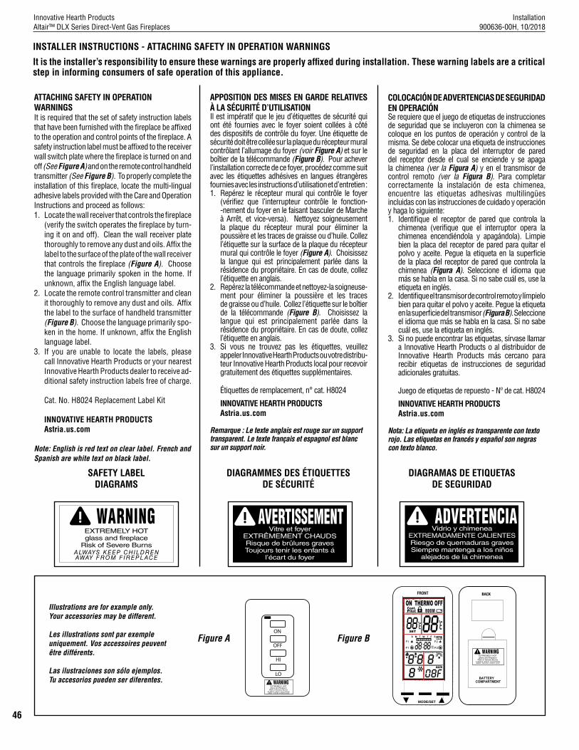
Installation 900636-00H, 10/2018
Innovative Hearth ProductsAltair™ DLX Series Direct-Vent Gas Fireplaces
46
ATTACHING SAFETY IN OPERATION WARNINGSIt is required that the set of safety instruction labels that have been furnished with the fireplace be affixed to the operation and control points of the fireplace. A safety instruction label must be affixed to the receiver wall switch plate where the fireplace is turned on and off (See Figure A) and on the remote control handheld transmitter (See Figure B). To properly complete the installation of this fireplace, locate the multi-lingual adhesive labels provided with the Care and Operation Instructions and proceed as follows:1. Locate the wall receiver that controls the fireplace
(verify the switch operates the fireplace by turn-ing it on and off). Clean the wall receiver plate thoroughly to remove any dust and oils. Affix the label to the surface of the plate of the wall receiver that controls the fireplace (Figure A). Choose the language primarily spoken in the home. If unknown, affix the English language label.
2. Locate the remote control transmitter and clean it thoroughly to remove any dust and oils. Affix the label to the surface of handheld transmitter (Figure B). Choose the language primarily spo-ken in the home. If unknown, affix the English language label.
3. If you are unable to locate the labels, please call Innovative Hearth Products or your nearest Innovative Hearth Products dealer to receive ad-ditional safety instruction labels free of charge.
Cat. No. H8024 Replacement Label Kit
INNOVATIVE HEARTH PRODUCTSAstria.us.com
Note: English is red text on clear label. French and Spanish are white text on black label.
APPOSITION DES MISES EN GARDE RELATIVES À LA SÉCURITÉ D’UTILISATIONIl est impératif que le jeu d’étiquettes de sécurité qui ont été fournies avec le foyer soient collées à côté des dispositifs de contrôle du foyer. Une étiquette de sécurité doit être collée sur la plaque du récepteur mural contrôlant l’allumage du foyer (voir Figure A) et sur le boîtier de la télécommande (Figure B). Pour achever l’installation correcte de ce foyer, procédez comme suit avec les étiquettes adhésives en langues étrangères fournies avec les instructions d’utilisation et d’entretien :1. Repérez le récepteur mural qui contrôle le foyer
(vérifiez que l’interrupteur contrôle le fonction --nement du foyer en le faisant basculer de Marche à Arrêt, et vice-versa). Nettoyez soigneusement la plaque du récepteur mural pour éliminer la poussière et les traces de graisse ou d’huile. Collez l’étiquette sur la surface de la plaque du récepteur mural qui contrôle le foyer (Figure A). Choisissez la langue qui est principalement parlée dans la résidence du propriétaire. En cas de doute, collez l’étiquette en anglais.
2. Repérez la télécommande et nettoyez-la soigneuse-ment pour éliminer la poussière et les traces de graisse ou d’huile. Collez l’étiquette sur le boîtier de la télécommande (Figure B). Choisissez la langue qui est principalement parlée dans la résidence du propriétaire. En cas de doute, collez l’étiquette en anglais.
3. Si vous ne trouvez pas les étiquettes, veuillez appeler Innovative Hearth Products ou votre distribu-teur Innovative Hearth Products local pour recevoir gratuitement des étiquettes supplémentaires.
Étiquettes de remplacement, n° cat. H8024
INNOVATIVE HEARTH PRODUCTSAstria.us.com
Remarque : Le texte anglais est rouge sur un support transparent. Le texte français et espagnol est blanc sur un support noir.
COLOCACIÓN DE ADVERTENCIAS DE SEGURIDAD EN OPERACIÓNSe requiere que el juego de etiquetas de instrucciones de seguridad que se incluyeron con la chimenea se coloque en los puntos de operación y control de la misma. Se debe colocar una etiqueta de instrucciones de seguridad en la placa del interruptor de pared del receptor desde el cual se enciende y se apaga la chimenea (ver la Figura A) y en el transmisor de control remoto (ver la Figura B). Para completar correctamente la instalación de esta chimenea, encuentre las etiquetas adhesivas multilingües incluidas con las instrucciones de cuidado y operación y haga lo siguiente:1. Identifique el receptor de pared que controla la
chimenea (verifique que el interruptor opera la chimenea encendiéndola y apagándola). Limpie bien la placa del receptor de pared para quitar el polvo y aceite. Pegue la etiqueta en la superficie de la placa del receptor de pared que controla la chimenea (Figura A). Seleccione el idioma que más se habla en la casa. Si no sabe cuál es, use la etiqueta en inglés.
2. Identifique el transmisor de control remoto y límpielo bien para quitar el polvo y aceite. Pegue la etiqueta en la superficie del transmisor (Figura B). Seleccione el idioma que más se habla en la casa. Si no sabe cuál es, use la etiqueta en inglés.
3. Si no puede encontrar las etiquetas, sírvase llamar a Innovative Hearth Products o al distribuidor de Innovative Hearth Products más cercano para recibir etiquetas de instrucciones de seguridad adicionales gratuitas.
Juego de etiquetas de repuesto - Nº de cat. H8024
INNOVATIVE HEARTH PRODUCTSAstria.us.com
Nota: La etiqueta en inglés es transparente con texto rojo. Las etiquetas en francés y español son negras con texto blanco.
INSTALLER INSTRUCTIONS - ATTACHING SAFETY IN OPERATION WARNINGS
It is the installer’s responsibility to ensure these warnings are properly affixed during installation. These warning labels are a critical step in informing consumers of safe operation of this appliance.
SAFETY LABEL DIAGRAMS
DIAGRAMAS DE ETIQUETAS DE SEGURIDAD
DIAGRAMMES DES ÉTIQUETTES DE SÉCURITÉ
MODE/SET
Cont.
S M T W T F S
AMPM
ROOM
SET
P1
A B
P2P2
AUX
P2
Pilot
:
OFFON
°°
u
PROGRAM
USB
MODE/SET
BATTERYCOMPARTMENT
BACKFRONT
Figure A Figure B
Illustrations are for example only. Your accessories may be different.
Les illustrations sont par exemple uniquement. Vos accessoires peuvent être différents.
Las ilustraciones son sólo ejemplos. Tu accesorios pueden ser diferentes.
ON
OFF
HI
LO

Installation 900636-00H, 10/2018
Innovative Hearth ProductsAltair™ DLX Series Direct-Vent Gas Fireplaces
47
Cat. No. Model Description
H1968 SV4.5HT-2Horizontal Square Termination with Firestop/Spacer (H2246),
and Adaptor (74L61)
H2152 SV4.5CGV-1 Vertical Termination Cap, High Wind
H8914 SV4.5TK90HT2 Horizontal Termination Kit HT-2 with 90° elbow
Vent Sections (Rigid)
77L70 SV4.5L6 6” (152 mm)
77L71 SV4.5L12 12” (305 mm)
77L72 SV4.5L24 24” (610 mm)
77L73 SV4.5L36 36” (914 mm)
77L74 SV4.5L48 48” (1219 mm)
77L75 SV4.5LA Telescopic Length Slip Section (2 to 7-1/2” rigid)
77L76 SV4.5E45 45° Elbow
77L77 SV4.5E90 90° Elbow
H5816 750,247M
SV4.5-TWSK10
Through Wall Shield Kit (to shield direct-vent pipe from
blown insulation)(see 750247M)
96K93 SV4.5SU Support Strap
99L02 SV4.5HRK14 Horizontal Riser Kit, 14”(see 750146M)
99L03 SV4.5HRK36 Horizontal Riser Kit, 36”(see 750146M)
Cat. No. Model Description
H6183 SV4.5HF5 Firestop Spacer, 5”, rigid
H6184 SF4.5HF5 Firestop Spacer, 5”, flex
H2246 SV4.5HF-10 Firestop/Spacer-Horizontal, rigid (3-1-1 spacing), 10 Pack
H2247 SV4.5VF-10 Firestop/Spacer-Vertical, rigid (1-1-1 spacing), 10 Pack
96K92 SV4.5SP Support Plate
87L02 SV4.5HGS
Termination Guard for Horizontal Square Termination
(Deluxe)(1 pack) (see 750055M)
H5820 SV4.5HTSK
Termination Shroud (Guard) for Horizontal Square Termination (1 pack)
(see 750246M)
H3907 SV4.5ARSA Attic Insulation Shield with adjustable height, 12 to 22”
Sealant
10K81 SFMP Mill-Pac, Black, High-Temperature Sealant
89L40 SFMP-12Mill-Pac, Black, High-Temperature Sealant
(bulk 12-pack)
F3191 SV4.5AdaptorKit
Secure Flex Adaptor KitIncludes rigid to flex adaptor
and flex to rigid adaptor(flex not included)
Listed Secure Vent® Components
INSTALLATION ACCESSORIES IMPORTANT NOTE: The installation accessories shown in this section are part of the safety agency listing for the product models represented in this manual.

Installation 900636-00H, 10/2018
Innovative Hearth ProductsAltair™ DLX Series Direct-Vent Gas Fireplaces
48
INSTALLATION ACCESSORIES (continued)
Cat. No. Model Description
60L10 SF-18 18 ft (5.49 m)* compressed flex (see 750053M)
98K03 SF-12 12 ft (3.66 m)*compressed flex(see 750052M)
H2248 SF4.5HF-10 Firestop/Spacer, Horizontal, flex(3-1-1 spacing), 10 Pack
H2249 SF4.5VF-10 Firestop/Spacer, Vertical, flex(1-1-1 spacing),10 Pack
H1969 SF4.5HT-2 Horizontal Square Termination for flex (without flex)
77L87 SFKIT12S Square Term. for flex with 12” (305 mm)* compressed flex
77L88 SFKIT18S Square Term. for flex with 18” (457 mm)* compressed flex
77L89 SFKIT24S Square Term. for flex with 24” (610 mm)* compressed flex
77L90 SFKIT36S Square Term. for flex with 36” (914 mm)* compressed flex
77L91 SFKIT48S Square Term. for flex with 48” (1219 mm)* compressed flex
91L66 SFGC4-6 Gear Clamp 4.5” (114 mm) for flex (6-pack)
91L67 SFGC7-6 Gear Clamp 7.5” (190.5 mm) for flex (6 pack)
Listed Secure Flex® Components
*All compressed flex vents can be expanded up to two times.
Cat. No. Model Description
56L74 SFVT30
Vertical Termination for flex (flat to 6/12) with flex adaptor, section of rigid vent, roof support collar
assembly, roof flashing and storm collar. (see 750052M)
56L75 SFVT45
Vertical Termination for flex (6/12 to 12/12) with flex adaptor, section
of rigid vent, roof support collar assembly, roof flashing and storm
collar. (see 750052M)
H7748 H7748
36” Flex Connector Kit. 36” of flex with two adaptors for mating two rigid sections of vent
together.

Installation 900636-00H, 10/2018
Innovative Hearth ProductsAltair™ DLX Series Direct-Vent Gas Fireplaces
49
GAS CONVERSION KITS
WARNING This conversion kit shall be installed by a qualified service agency in accordance with the manufacturer’s instructions and all applicable codes and requirements of the authority having jurisdiction. If the information in these instructions is not followed exactly, a fire, explosion, or the production of carbon monoxide may result; causing property damage, personal injury, or loss of life. The qualified service agency is responsible for the proper installation of this kit. The installation is not proper and complete until the operation of the converted appliance is checked as specified in the manufacturer’s instructions supplied with the kit. The qualified service agency performing this installation assumes responsibility for this conversion.
AVERTISSEMENT Cette trousse de conversion doit être installée par un technicien agréé, selon les instructions du fabricant et selon toutes les exigences et tous les codes pertinents de l’autorité compétente. Assurez-vous de bien suivre les instructions dans cette notice pour réduire au minimum le risque d’incendie, d’explosion ou la production de monoxyde de carbone pouvant causer des dommages matériels, des blessures ou la mort. Le tecnicien agréé est responsable de l’installation de cette trousse. L’installation n’est pas adéquate ni complète tant que le bon fonctionnement de l’appareil converti n’a pas été vérifié selon les instructions du fabricant fournies avec la trousse. Le fournisseur de service qualifié ayant réalisé l’installation assume les responsabilités liées à la conversion.
In Canada:
The conversion shall be carried out in accordance with the requirements of the provincial authorities having jurisdiction and in accordance with the requirements of the CAN/CGA-B149.1 Installation code.
La conversion devra être effectuée conformément aux recommandations des autorités provinciales ayant juridiction et conformément aux exigences du code d’installation CAN/CGA-B149.1.
Gas conversion kits are available to adapt your fireplace from the use of one type of gas to the use of another. These kits contain all the necessary components needed to complete the task including labeling that must be affixed to ensure safe operation.
Refer to the instructions provided with the conversion kit when performing any gas conversion.
Fireplace Models Model Catalog Number
40” Models GCK-SKT556151NP F2904
45” Models GCK-SKT526151NP F2906
Table 33A - Electronic Systems, Natural Gas To Propane Gas Conversion Kits (Ecoflow Fireplaces)
Fireplace Models Model Catalog Number
40” Models GCK-SKT385131PN F2905
45” Models GCK-SKT325031PN F2907
Table 33B - Electronic Systems, Propane Gas To Natural Gas Conversion Kits (Ecoflow Fireplaces)
Install gas conversion kits per instruction provided in kits.

Operation 900636-00H, 10/2018
Innovative Hearth ProductsAltair™ DLX Series Direct-Vent Gas Fireplaces
50
OPERATION
WARNING Young children should be carefully supervised when they are in the same room as the appliance. Toddlers, young children and others may be susceptible to accidental contact burns. A physical barrier is recommended if there are at risk individuals in the house. To restrict access to a fireplace or stove, install an adjustable safety gate to keep toddlers, young children and other at risk individuals out of the room and away from hot surfaces.
AVERTISSEMENT Les jeunes enfants devraient être surveillés étroitement lorsqu’ils se trouvent dans la même pièce que l’appareil. Les tout petits, les jeunes enfants ou les adultes peuvent subir des brûlures s’ils viennent en contact avec la surface chaude. Il est recommandé d’installer une barrière physique si des personnes à risques habitent la maison. Pour empêcher l’accès à un foyer ou à un poêle, installez une barrière de sécurité; cette mesure empêchera les tout petits, les jeunes enfants et toute autre personne à risque d’avoir accès à la pièce et aux surfaces chaudes.
WARNING Reinstall any barrier removed before operating the fireplace. The barrier is designed to reduce the risk of burns from hot glass. Do not operate the fireplace without the barrier installed.
WARNING Do not operate the fireplace if:• The glass front is removed, cracked, or broken• The surround trim assembly and screen are not installed
CARBON MONOXIDE POISONING: Early signs of carbon monoxide poisoning are similar to the flu with headaches, dizziness and/or nausea. If you have these signs, obtain fresh air immediately. Turn off the gas supply to the appliance and have it serviced by a qualified professional, as it may not be operating correctly. Some people are more affected by carbon monoxide than others, including pregnant women, people with heart or lung disease or anemia, those under the influence of alcohol, and those at high altitudes.
NOTE: Do not place furniture or other combustible materials within 36” of the front of viewing area(s).
NOTE: Children and adults should be alerted to the hazards of high surface temperature and should stay away to avoid burns or clothing ignition.
Remarqué : Les enfants et les adultes devraient être infor-més des dangers que posent les températures de surface élevées et se tenir à distance afin d’éviter des brûlures ou que leurs vêtements ne s’enflamment.
NOTE: Installation and repair should be done by a qualified service person. The fireplace should be inspected before use and at least annually by a professional service person. More frequent cleaning may be required due to excessive lint from carpeting, bedding material, etcetera. It is imperative that control compartments, burners and circulating air passageways of the fireplace be kept clean.
Remarqué : L’installation et la réparation devrait être confiées à un technicien qualifié. L’appareil devrait faire l’objet d’une inspection par un technicien professionnel avant d’être utilisé et au moins une fois l’an par la suite. Des nettoyages plus fréquents peuvent être nécessaires si les tapis, la literie, et cetera produisent une quantité importante de pous-sière. Il est essentiel que les compartiments abritant les commandes, les brûleurs et les conduits de circulation d’air de l’appareil soient tenus propres.
NOTE: Do not use these fireplaces if any part has been under water. Immediately call a qualified, professional service technician to inspect the fireplace and to replace any parts of the control system and any gas control which have been under water.
Remarqué : Ne pas utiliser cet appareil s’il a été plongé, même partiellement, dans l’eau. Appeler un technicien qualifié pour inspecter l’appareil et remplacer toute partie du système de commande et toute commande qui a été plongée dans l’eau.

Operation 900636-00H, 10/2018
Innovative Hearth ProductsAltair™ DLX Series Direct-Vent Gas Fireplaces
51
MODE/SET
Cont.
S M T W T F S
AMPM
ROOM
SET
P1
A B
P2P2
AUX
P2
Pilot
:
OFFON
°°
u
PROGRAM
USB
MODE/SET
BATTERYCOMPARTMENT
BACKFRONT
Figure A Figure B
Illustrations are for example only. Your accessories may be different.
Les illustrations sont par exemple uniquement. Vos accessoires peuvent être différents.
Las ilustraciones son sólo ejemplos. Tu accesorios pueden ser diferentes.
ON
OFF
HI
LO
ATTACHING SAFETY IN OPERATION WARN-INGS
Your fireplace has been furnished with safety instruc-tion labels that are to be affixed to the operation and control points of the fireplace. A safety instruction label should be affixed to the receiver wall switch plate where the fireplace is turned on and off (See Figure A) and the remote control handheld transmitter (Figure B). The warnings should already have been put in place when the fireplace initial set-up was completed. If they are not affixed at these spots, locate the multi-lingual adhesive labels provided with these instructions and proceed as follows:1. Locate the wall receiver that controls the fireplace
(verify the switch operates the fireplace by turn-ing it on and off). Clean the wall receiver plate thoroughly to remove any dust and oils. Affix the label to the surface of the plate of the wall receiver that controls the fireplace (Figure A). Choose the language primarily spoken in the home.
2. Locate the remote control transmitter and clean it thoroughly to remove any dust and oils. Affix the label to the surface of handheld transmitter (Figure B). Choose the language primarily spoken in the home.
3. If you are unable to locate the labels, please call Innovative Hearth Products or your nearest Innovative Hearth Products dealer to receive ad-ditional safety instruction labels free of charge.
Cat. No. H8024 Replacement Label Kit
INNOVATIVE HEARTH PRODUCTSAstria.us.com
Note: English is red text on clear label. French and Spanish are white text on black label.
APPOSITION DES MISES EN GARDE RELATIVES À LA SÉCURITÉ D’UTILISATION
Votre foyer a été livré avec des étiquettes de sécurité qui doivent être collées à côté des dispositifs de contrôle du foyer. Une étiquette de sécurité devrait être collée sur la plaque du récepteur mural contrôlant l’allumage du foyer (voir Figure A) et sur le boîtier de la télécommande (Figure B). Les mises en garde auraient dû être collées au moment de l’installation initiale du foyer. Si ce n’est pas le cas, prenez les étiquettes adhésives multilingues fournies avec ces instructions et procédez comme suit:1. Repérez le récepteur mural qui contrôle le foyer
(vérifiez que l’interrupteur contrôle le fonction-nement du foyer en le faisant basculer de Marche à Arrêt, et vice-versa). Nettoyez soigneusement la plaque du récepteur mural pour éliminer la poussière et les traces de graisse ou d’huile. Collez l’étiquette sur la surface de la plaque du récepteur mural qui contrôle le foyer (Figure A). Choisissez la langue qui est principalement parlée dans la résidence du propriétaire.
2. Repérez la télécommande et nettoyez-la soigneuse-ment pour éliminer la poussière et les traces de graisse ou d’huile. Collez l’étiquette sur le boîtier de la télécommande (Figure B). Choisissez la langue qui est principalement parlée dans la résidence du propriétaire.
3. Si vous ne trouvez pas les étiquettes, veuillez appeler Innovative Hearth Products ou votre distribu teur Innovative Hearth Products local pour recevoir gratuitement des étiquettes supplémentaires.
Étiquettes de remplacement, n° cat. H8024
INNOVATIVE HEARTH PRODUCTSAstria.us.com
Remarque : Le texte anglais est rouge sur un support transparent. Le texte français et espagnol est blanc sur un support noir.
COLOCACIÓN DE ADVERTENCIAS DE SEGURIDAD EN OPERACIÓN
Su chimenea incluye etiquetas de instrucciones de seguridad que deben colocarse en los puntos de operación y control de la chimenea. Se debe colocar una etiqueta de instrucciones de seguridad en la placa del interruptor de pared del receptor desde el cual se enciende y se apaga la chimenea (ver la Figura A) y en el transmisor de control remoto (Figura B). Las advertencias ya deben haberse colocado cuando se completó la instalación inicial de la chimenea. Si no están colocadas en estos lugares, encuentre las etiquetas adhesivas multilingües proporcionadas con estas instrucciones y prosiga de la siguiente manera:1. Identifique el receptor de pared que controla la
chimenea (verifique que el interruptor opera la chimenea encendiéndola y apagándola). Limpie bien la placa del receptor de pared para quitar el polvo y aceite. Pegue la etiqueta en la superficie de la placa del receptor de pared que controla la chimenea (Figura A). Seleccione el idioma que más se habla en la casa.
2. Identifique el transmisor de control remoto y límpielo bien para quitar el polvo y aceite. Pegue la etiqueta en la superficie del transmisor (Figura B). Seleccione el idioma que más se habla en la casa.
3. Si no puede encontrar las etiquetas, sírvase llamar a Innovative Hearth Products o al distribuidor de Innovative Hearth Products más cercano para recibir etiquetas de instrucciones de seguridad adicionales gratuitas.
Juego de etiquetas de repuesto - Nº de cat. H8024
INNOVATIVE HEARTH PRODUCTSAstria.us.com
Nota: La etiqueta en inglés es transparente con texto rojo. Las etiquetas en francés y español son negras con texto blanco.
HOMEOWNER’S INSTRUCTIONS - ATTACHING SAFETY IN OPERATION WARNINGS
SAFETY LABEL DIAGRAMS DIAGRAMAS DE ETIQUETAS DE SEGURIDAD
DIAGRAMMES DES ÉTIQUETTES DE SÉCURITÉ

Operation 900636-00H, 10/2018
Innovative Hearth ProductsAltair™ DLX Series Direct-Vent Gas Fireplaces
52
Burn-in Period
The first few times this fireplace is operated, there will be an odor from the curing of paint and the burning off of the lubricants used in the manufacturing process. Depending on usage, the burn-in period may take a few hours or a few days.
NOTE: Ventilate the site during the burn-in period. The resulting odor and haze may set off a smoke detector. Do not operate the blower during the burn-in period.
A white film may develop on the glass front during the first few fires as part of the burn-in period. The glass should be kept clean during the burn-in period to prevent the film from baking on—making it very difficult to remove (Cleaning the glass door on Page 58).
Accessing the Control Compartment
Opening the Control Compartment Door
1. Grasp the top of the control compartment door and gently pull it to release the door from the magnet. Lower the door until it stops (see Figure 38).
Closing the Control Compartment Door
1. Swing the control compartment door gently up until the magnet engages the door in the closed position.
Removing the Control Compartment Door
1. Open the lower control compartment door (see instructions above).
2. Remove the control compartment door by sliding the hinge pin, located at the door’s left side, to the right until it disengages from the left corner post hole. Pull the door diagonally to the left, away from the fireplace (see Figure 38).
Figure 38 - Control compartment door
Electronic Fireplaces
Detailed lighting instructions are found on Page 62. Also, electronic fireplace lighting instructions are found on the pull-out lighting instructions attached to the gas control valve.If the electronic fireplace is equipped with an remote wall switch or remote control, the fireplace main burner can be turned ON/OFF with the wall switch or remote control.
To light the fireplace in a power outage:
1. Confirm that batteries are installed in the Wall Switch
2. Set the unit-mounted switch, or wall switch to the ON Position.
3. The unit should spark at the pilot and light.
NOTE: If there is no spark, replace the batteries.
4. Operate the fireplace normally.
Control CompartmentAccess Door
Magnet
ControlCompartment
Hinge Pin
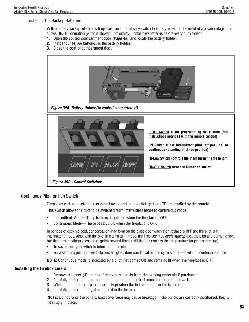
Operation 900636-00H, 10/2018
Innovative Hearth ProductsAltair™ DLX Series Direct-Vent Gas Fireplaces
53
Installing the Backup Batteries
With a battery backup, electronic fireplaces can automatically switch to battery power. In the event of a power outage, this allows ON/OFF operation (without blower functionality). Install new batteries before every burn season. 1. Open the control compartment door (Page 40), and locate the battery holder.2. Install four (4) AA batteries in the battery holder.3. Close the control compartment door.
Continuous Pilot Ignition Switch
Fireplaces with an electronic gas valve have a continuous pilot ignition (CPI) controlled by the remote
This switch allows the pilot to be switched from intermittent mode to continuous mode:
• Intermittent Mode—The pilot is extinguished when the fireplace is OFF.• Continuous Mode—The pilot stays ON when the fireplace is OFF.
In periods of extreme cold, condensation may form on the glass door when the fireplace is OFF and the pilot is in intermittent mode. Also, with the pilot in intermittent mode, the fireplace may cycle startup (i.e., the pilot and burner ignite, but the burner extinguishes and reignites several times until the flue reaches the temperature for proper drafting).• To save energy—switch to intermittent mode. • For a standing pilot that will help prevent glass door condensation and cycle startup—switch to continuous mode.
NOTE: Continuous mode is indicated by a pilot that comes ON and remains lit when the fireplace is OFF.
Installing the Firebox Liners1. Remove the three (3) optional firebox liner panels from the packing materials if purchased.2. Carefully position the rear panel, upper edge first, in the firebox against the rear wall.3. While holding the rear panel, carefully position the left side panel in the firebox. 4. Carefully position the right side panel in the firebox.
NOTE: Do not force the panels. Excessive force may cause breakage. If the panels are correctly positioned, they will fit snugly in place.
Figure 39A- Battery Holder (in control compartment)
Learn Switch is for programming the remote (see instructions provided with the remote control)
IPI Switch is for intermittent pilot (off position) or continuous / standing pilot (on position)
Hi-Low Switch controls the main burner flame height
ON/OFF Switch turns the burner on and off
Figure 39B - Control Switches

Operation 900636-00H, 10/2018
Innovative Hearth ProductsAltair™ DLX Series Direct-Vent Gas Fireplaces
54
Install the Logs, Volcanic Stone, and Glowing Embers
WARNING • Turn OFF all gas and electricity to the appliance before installing the volcanic stone, embers, and logs.• Do NOT install the logs until the appliance has been completely installed, the gas line connected and
tested for leaks, and the initial burner operation has been confirmed.• Use of an unapproved log set in the fireplace will void the warranty and will result in incomplete
combustion, sooting, and poor flame quality.• Logs get very hot and remain hot for up to one hour after the gas supply is turned OFF. Handle the logs
only when cool. • This appliance is not designed to burn wood. Any attempt to do so could cause irreparable damage to
appliance and prove hazardous.• If the logs are not installed according to these instructions, improper combustion could occur. This could
result in the excessive production of soot and/or the colorless, odorless, toxic gas carbon monoxide (CO).
NOTE: It is important to ensure proper log placement per the manual when installing these units. Verify pilot flame is not obstructed. See Verifying Appliance Operation on Page 41.
NOTE: If applicable, install the firebox liner before placing the stone. Logs can be installed after the volcanic stone.
Installing the volcanic stone, and glowing embers
1. If necessary, remove the glass door (Page 57-58).
2. Spread the decorative volcanic stone in a pleasing pattern on the firebox floor along the slope and to the back right and left sides of the burner (Figure 40).
NOTE: Do not place stone on the burner.
3. Separate and fluff the glowing embers into pieces approximately the size of a quarter (Figure 41).
Figure 40 - Install volcanic stone Figure 41 - Separate glowing embers
4. Position the separated glowing embers over the small holes on the burner surface as shown in Figure 42. Do NOT cover the large burner slots.
Figure 42 - Install glowing embers
NOTE: Enough glowing ember material is provided for several applications. For best glowing effect, replace the ember material annually.
VolcanicStone
Glowing Embers

Operation 900636-00H, 10/2018
Innovative Hearth ProductsAltair™ DLX Series Direct-Vent Gas Fireplaces
55
Installing the Altair™ DLX Series 40” and 45” logsThe logs have notches/tabs to assist proper positioning. Upper logs rest on lower logs via notches/tabs. Proper log placement is critical to prevent sooting. Place the logs in the gaps between flame peaks, so they do not impinge the flames. Follow the log placement instructions precisely.
NOTE: Do not cover the burner ports.
1. If necessary, remove the glass door (Pages 57-58).
2. Position the rear log #1 (Figures 44) on the two rear setting pins shown in Figures 43.
Figure 43 - Locate log setting pins Figure 44 - Place log #1
3. Place the left rear log #2 (Figure 45) over the 2 left pins on log #1 (Figure 44).
4. Place the upper right rear log #3 (Figure 46) over the 2 right pins on log #1 (Figure 44).
Figure 45 - Place log #2 Figure 46 - Place log #3
Table 34 - 40” and 45” Log Sets
Log Number Description
1 Bottom Rear Log
2 Upper Left Rear Log3 Upper Right Rear Log4 Middle Left Log5 Front Left Log
6 Front Right Forked Log
7 Upper Right Forked Log
Catalog number for the entire set:J8300 - 40”; J8302 - 45”
4
1
2 3
5 7
6
The setting pins, indicated by the arrows, are for the middle and rear log.
1Grate
2 3

Operation 900636-00H, 10/2018
Innovative Hearth ProductsAltair™ DLX Series Direct-Vent Gas Fireplaces
56
5. Place the middle left log #4 (Figure 47) on the setting pins in the middle of the grate (Figure 43).
6. Place the front left forked log #5 over log #4 as shown in Figure 48. One foot will rest between the 2nd and 3rd bar from the left on the grate.
Figure 47 - Place log #4 Figure 48 - Place log #5
Figure 49 - Place log #6
7. The front right forked log #6 will roll back onto log #4 (Figure 49). It has a setting pin which should face out from the rest of the logs.
8. The upper right forked log #7 is the final log in this process (Figure 50). It rests on the 4th bar, on the setting pin of log #6 and on log #3.
Figure 50 - Place log #7
4
5
67

Operation 900636-00H, 10/2018
Innovative Hearth ProductsAltair™ DLX Series Direct-Vent Gas Fireplaces
57
WARNING • Do not attempt to substitute the materials used on these doors, or replace cracked or broken glass. • Handle this glass with extreme care! Glass is susceptible to damage—Do not scratch or handle roughly
while reinstalling the glass door frame.• The glass door of this appliance must only be replaced as a complete unit as provided by the
manufacturer. Do not attempt to replace broken, cracked or chipped glass separately. • Do not attempt to touch the front enclosure glass with your hands while the fireplace is in use.
WARNING A barrier designed to reduce the risk of burns from the hot viewing glass is provided with this appliance and shall be installed.
AVERTISSEMENT Une barrière conçue pour réduire le risque de brûlure par le hublot chaude est fournie avec l’appareil et doit être installé.
WARNING Do not operate appliance with the glass front removed, cracked, or broken.
AVERTISSEMENT Ne pas utiliser l’appareil si le panneau frontal en verre n’est pas en place, est craqué, ou brisé.
WARNING Any safety screen, guard or barrier removed for servicing an appliance must be replaced prior to operating the appliance.
AVERTISSEMENT Tout écran ou protecteur retiré pour permettre l’entretien de l’appareil doit être remis en place avant de mettre l’appareil en marche.
Only doors certified with the fireplace shall be used. Seules des portes certifiées pour cet appareil doivent être utilisées.
Installing and removing the glass door
WARNINGDo NOT abuse the glass door by striking it or slamming it shut.
WARNINGThe door should easily close without needing to be pressed down. If it has to be pressed down to close, the gasket in the top of the door should be dressed so it lays on the glass.

Operation 900636-00H, 10/2018
Innovative Hearth ProductsAltair™ DLX Series Direct-Vent Gas Fireplaces
58
Installing the glass door
1. Visually inspect the gasket on the backside of the glass door.
NOTE: The gasket surface must be clean, free of irregularities, and seated firmly. Ensure it is properly located. Make sure the bead is not rolled into the channel at the top of the door, but remains flat against the top of the glass.
2. Position the door in front of the firebox opening with the bottom of the door held away from the fireplace at a 45° angle (Figure 55). Hook the top flange of the door frame over the top of the firebox frame.
NOTE: Ensure the glass door is centered—with even spacing on each side.
3. Let the bottom of the glass door swing gently in towards the fireplace ensuring that the gasket seats evenly as the door draws shut. Securely fasten the two (2) latches beneath the firebox floor to the door V-flange.
4. Install the barrier.
5. Close the control compartment door.
Removing the glass door
1. Open the control compartment door (Page 51).
NOTE: If necessary, remove the door and place it in a safe location for later reinstallation.
2. Remove the barrier. Place the barrier in a safe location for later reinstallation.
3. Detach the two (2) door latches beneath the firebox floor.
4. Swing the bottom of the glass door away from the fireplace to a 45° angle (Figure 55)
5. Carefully grip the door at the top and bottom, and remove it from the fireplace. Place the door in a safe location for later reinstallation.
Figure 51 - Glass Door Figure 52 - Barrier
Latch
Control Compartment
Door
Glass Door
Hood
NOTICE: All Altair™ DLX Series fireplaces include a barrier to reduce the risk of burns from hot viewing glass. This barrier in the fireplace is a screen shown below;
40” Barrier F184045” Barrier F1903

Operation 900636-00H, 10/2018
Innovative Hearth ProductsAltair™ DLX Series Direct-Vent Gas Fireplaces
59
MAINTENANCE
Refer to the Maintenance Schedule on Page 61 for maintenance tasks, procedures, frequency, and a listing of by whom the tasks should be performed. Always verify proper fireplace operation after servicing.
WARNING Turn OFF gas and electrical power to the fireplace and allow it to cool before cleaning or servicing the appliance.
CAUTION Wear gloves and safety glasses for protection while doing required maintenance.
Verify proper operation after servicing.S’assurer que l’appareil fonctionne adéquatement une fois l’entretien terminé.
Always turn OFF gas before cleaning. Before relighting, refer to the lighting instructions in this manual. Instructions are also found on a pull-out panel located in the control compartment.Always keep the appliance area clear and free from combustible materials, gasoline and other flammable liquids.
NOTE: Prior to the first use of the fireplace and each burn season and periodically during the burn season, inspect the horizontal termination for debris such as bird nests, leaves, paper or branches. Remove any items from the surfaces of the termination prior to use. Also be aware of shrubs and plantings that may encroach on the termination.
Inspecting the venting system
The fireplace and venting system should be thoroughly inspected before initial use and at least annually by a qualified service technician. Inspection should include ensuring that exhaust or intake passages are unobstructed and vent components are properly assembled and not damaged. The homeowner must contact a qualified service technician at once if any abnormal condition is observed.If the venting system is disassembled for any reason, a qualified service technician should follow vent installation instructions for proper reassembly and proper sealing of the venting system components. However, more frequent periodic inspections and cleanings should be performed by the homeowner.
NOTE: Inspect exhaust termination for blockage or obstruction such as plants, bird nests, leaves, snow, debris, etc.
NOTE: Prior to the first use of the fireplace and each burn season and periodically during the burn season, inspect the horizontal termination for debris such as bird nests, leaves, paper or branches. Remove any items from the surfaces of the termination prior to use. Also be aware of shrubs and plantings that may encroach on the termination.
Inspect burner flame and pilot flame appearance
Periodically inspect the burner and pilot flame. Ensure that the burner flame appearance resembles the flame shown in Figure 36 on Page 44 and as described in Flame Appearance and Sooting on Page 43. Any necessary burner flame adjustments must be performed by qualified personnel only (Page 43). Refer to Page 41 for more information about the pilot flame appearance. Contact a qualified service technician at once if any abnormal condition is observed.
Cleaning the glass door
WARNING Do not use abrasive cleaners on glass. Never clean the glass when it is hot.
Clean the glass during the Burn-in Period, and then only when necessary and when the fireplace is cool. Wipe the surface with a clean, dampened, soft cloth. Follow with a dry, soft towel as desired. Take care not to scratch the glass surface. Periodically, remove any build-up caused by the following:• During start-up, it is normal for condensation to form on the inside of the glass (this condensation and fog will
usually disappear in a few minutes). The moisture can cause lint, dust and other airborne particles to cling to the glass surface.
• Initial curing of the high temperature paint and burning off of lubricants used in the manufacturing process may result in a film on the glass.
• A white coating may form on the glass as a result of impurities and minerals in the fuel. Clean the glass two or three times each heating season, depending on the circumstances present. The following cleaning solutions are approved for use:• Non-ammonia based glass cleaner• Gas fireplace/stove glass cleaner

Operation 900636-00H, 10/2018
Innovative Hearth ProductsAltair™ DLX Series Direct-Vent Gas Fireplaces
60
Inspecting the glass gasket
Visually inspect the gasket on the backside of the glass door. The gasket surface must be clean, free of irregularities, and seated firmly.
Cleaning the control compartment
Keep the control compartment clean by vacuuming or brushing it out at least twice a year. More frequent cleaning may be required due to excessive lint from carpeting, bedding material, etcetera. It is imperative that control compartments, burners and circulating air passageways of the appliance be kept clean.
Touching up paint in small areas
Only use a factory-supplied paint kit for any touch-ups. Paint is available at your local IHP dealer. Never attempt to paint a hot fireplace. Do not attempt to repaint the fireplace until the finish is completely cured (Burn-in Period on Page 52). If the surface becomes stained or marred, it may be lightly sanded and touched up.
Logs
Removing and cleaning the logs
CAUTION The fiber logs become very fragile after curing.
Carefully remove the logs. Clean carbon from the logs using a vacuum cleaner, or a soft bristle brush (e.g., paint brush).
Reinstalling the embers and logs
Carefully follow the placement instructions (Pages 54–56). All logs should fit onto the corresponding pins and/or log stoppers. This will ensure proper flame and safe combustion.
NOTE: Improper positioning of logs can create carbon build-up and will alter the performance of the fireplace.
Replacing the logs
If the logs become damaged and need replacement, use only the proper replacement logs from manufacturer (Page 66).
Cleaning the burner
Carefully remove the logs/media. Vacuum out any foreign matter on the burner (e.g., lint, carbon, etc.). Ensure the burner ports are free of debris.
NOTE: Improper positioning of logs/media can create carbon build-up and will alter the performance of the fireplace.
Inspecting the wiring
Refer to the wiring diagram (Figure 31, Page 39).
CAUTION When servicing controls, label all wires prior to disconnection. Wiring errors can cause improper and dangerous operation. Verify proper operation after servicing.
ATTENTION Au moment de l’entretien des commandes, étiquetez tous les fils avant de les débrancher. Des erreurs de cáblage peuvent entraîner un fonctionnement inadéquat et dangereux.
Inspect and clean all wire connections. Ensure that there is no wire melting or damage. The inspection should include:
• Terminals at the valve• ON/OFF switch• Remote control, or unit-mounted switch

Operation 900636-00H, 10/2018
Innovative Hearth ProductsAltair™ DLX Series Direct-Vent Gas Fireplaces
61
MAINTENANCE SCHEDULE
See the tables below for detailed information about required maintenance, both regular and annual.
Maintenance Performed Annually—Before the Burning Season
Maintenance Task Performed By Procedure
Inspecting/Cleaning Burner, Logs, and Controls
Qualified Service Technician Inspect valve and ensure it is properly operating. Check piping for leaks. Vacuum the control compartment, fireplace logs and burner area.
Check Flame Patterns and Flame Height Qualified Service Technician Verify the flame pattern and height displayed by the appliance. Flames must not impinge on the logs.
Inspecting/Cleaning Pilot and Burner Qualified Service Technician Remove any surface build-up on pilot and burner assembly. Wipe the pilot nozzles, ignitor/flame rod and hood. Ensure the pilot flame engulfs the flame sensor as shown.
Checking Vent System Qualified Service Technician Inspect the vent system at the top and at the base (within the firebox) for signs of blockage or obstruction. Look for any signs of dislocation of the vent components.
Appliance Inspection Qualified Service Technician Perform the appropriate appliance inspection procedure detailed in this manual.
Replacing Glowing Embers Material Homeowner/Qualified Services Technician Remove old ember materials and vacuum the glowing embers (rockwool) placement area. Place new glowing embers as described in this document.
Maintenance Performed Periodically—After the Burning Season
Maintenance Task Performed By Procedure
Cleaning Firebox Interior Homeowner Carefully remove logs and glowing embers (rockwool). Vacuum out interior of the firebox. Clean firebox walls and log grate. Replace logs and glowing embers as detailed in this manual.
Check Flame Patterns and Flame Height Homeowner Verify the flame pattern and height displayed by the appliance. Flames must not impinge on the logs.
Checking Vent System Homeowner Inspect the vent system at the top and at the base (within the firebox) for signs of blockage or obstruction. Look for any signs of dislocation of the vent components.
Cleaning Front Glass Door Homeowner Clean as necessary following the directions provided in this manual.
Do not touch or attempt to clean the glass while hot.

Operation 900636-00H, 10/2018
Innovative Hearth ProductsAltair™ DLX Series Direct-Vent Gas Fireplaces
62
ACCESSORY COMPONENTS
Touch-Up Paint Kits
Repair minor scratches and discoloration of the fireplace black painted surfaces with the touch-up paint kits.
Cat. No. Model Description
F3373 --- Black touch-up paint, firebox interior
F1882 SCTPSAB Black touch-up paint, powder coat exterior
Cat. No. Model Description
88L53 FGE Bag of Glowing Embers
H8312 PGE Bag of Platinum Embers
80L42 FDVS Bag of Volcanic Stone
PA I N T
Bag of Glowing EmbersBag of Platinum EmbersBag of Volcanic StoneReplacement ember materials or volcanic stone are available for use with these ap-pliances. Order kits as part of the periodic maintenance of the appliance.
Black Reflective Porcelain Firebox Liner Kits
Firebox Liner Kits
Cat. No. Model Description Used on
F2914 BPLK40-DVA Black Reflective 40” Models
F2915 BPLK45-DVA Black Reflective 45” Models
Table 2 - Black Reflective Porcelain Liner Kit
Cat. No. Model Description Used on
F2908 EBLK40OTR-S Old Town RedCeramic Stacked
40” Models
F2910 EBLK40BT-S Black TieCeramic Stacked
F2909 EBLK40BWN-S Heritage BrownCeramic Stacked
F3428 EBLK40OTR-H Tacoma RedCeramic Herringbone
F2914 BPLK40-DVA Black Reflective Porcelain
F2911 EBLK45OTR-S Old Town RedCeramic Stacked
45” Models
F2913 EBLK45BT-S Black TieCeramic Stacked
F2912 EBLK45BWN-S Heritage BrownCeramic Stacked
F3429 EBLK45OTR-H Tacoma RedCeramic Herringbone
F2915 BPLK45-DVA Black Reflective Porcelain
Deluxe Termination Guard
(fits 94L10 and H1968)
Termination Shroud (fits H1968)
Cat. No. Model Description
H5820 4.5HTSK Termination Shroud
87L02 SV4.5HGS Termination Guard, Deluxe
Table 3 - Termination Guard Kits
Termination Guard Kits
The vent termination guards may be used to minimize exposure to the hot surface of the termination.
Table 4 - Glowing Embers, Platinum Embers and Volcanic Stone
Table 5 - Touch-Up Paint Kit
Old Town Red - Stacked
Black Tie - Stacked
Tacoma Red - Herringbone
Heritage Brown - Stacked
Black Reflective - Porcelain
Firebox Liner Kit

Operation 900636-00H, 10/2018
Innovative Hearth ProductsAltair™ DLX Series Direct-Vent Gas Fireplaces
63
LIGHTING INSTRUCTIONS, ELECTRONIC ECOFLOW - ENGLISH
1. Turn the wall switch or ON/OFF switch to "OFF.2. (if applicable) Press ON/OFF button on remote control transmitter to
"OFF."
P/N 900426-00, Rev. 4
FOR YOUR SAFETY READ BEFORE OPERATING
WARNING: If you do not follow these instructions exactly, a fire or explosion may result causing property damage, personal injury or loss of life.
A. This appliance is equipped with an ignition device which automatically lights the pilot. Do not try to light the pilot by hand.
B. BEFORE OPERATING smell all around the appliance area for gas. Be sure to smell next to the floor because some gas is heavier than air and will settle on the floor.
WHAT TO DO IF YOU SMELL GAS:
• Do not try to light any appliance.• Do not touch any electric switch; do not use any phone in your building.
OPERATING INSTRUCTIONS
TO TURN OFF GAS TO APPLIANCE
• Immediately call your gas supplier from a neighbor’s phone. Follow the gas supplier’s instructions.
• If you cannot reach your gas supplier, call the fire department.
C. If any portion of this appliance does not operate as the instructions indicate, do not try to repair it, call a qualified service technician. Do not use tools. Force or attempted repair may result in a fire or explosion.
D. Do not use this appliance if any part has been under water. Immediately call a qualified service technician to inspect the appliance and to replace any part of the control system and any gas control which has been under water.
Copreci Gas Valve
SwitchesElectronic PilotAssembly
3. Turn off all electric power to the appliance if service is to be performed. Note: The control may have a battery backup (remove batteries, if installed).
4. Close the main line gas shut-off valve.
1. STOP! Read the safety information above on this label.2. Read the Care and Operation manual including the section on "Remote
Control System," (if applicable).3. Turn the remote control, wall switch or ON/OFF switch to "OFF."4. Turn "OFF" all electric power to the appliance. Note: The control may
have a battery backup (remove batteries, if installed).5. This appliance is equipped with an ignition device which automatically
lights the pilot. Do not try to light the pilot by hand.6. Wait five (5) minutes to clear out any gas. Then smell for gas,
including near the floor. If you smell gas, STOP! Follow “B” in the safety information above on this label. If you don’t smell gas, go to the next step.
7. Turn on all electric power to the appliance. Note: The control may have a battery backup (install batteries, if applicable).
8. Turn the remote control, wall switch or ON/OFF switch to "ON."9. (if applicable) Set thermostat on remote control to desired setting.10. If the appliance will not operate, follow the instructions "To Turn Off
Gas To Appliance" and call your service technician or gas supplier.
DANGER HOT GLASS WILLCAUSE BURNS.
DO NOT TOUCH GLASSUNTIL COOLED.
NEVER ALLOW CHILDRENTO TOUCH GLASS.
A barrier designed to reduce the risk of burns from the hot viewing glass is provided with this appliance and shall be installed for the protection of children and other at-risk individuals.
Optional: Hi/Lo
Optional: IPI/Cont. Pilot
Learn (Some Models)
Yellow Wires
Blue Wires
Black Wires
On/Off
Brown Wires

Operation 900636-00H, 10/2018
Innovative Hearth ProductsAltair™ DLX Series Direct-Vent Gas Fireplaces
64
LIGHTING INSTRUCTIONS, ELECTRONIC ECOFLOW - FRENCH
P/N 900427-00, Rev. 4
AVERTISSEMENT. Quiconque ne respecte pas à la lettre les instructions dans la présente notice risque de déclencher un incendie ou une explosion entraînant des dommages, des blessures ou la mort.
A. Cet appareil est muni d’un dispositi f d’allumage qui allume automatiquement la veilleuse. Ne tentez pas d’allumer la veilleuse manuellement.
B. AVANT DE FAIRE FONCTIONNER, reniflez tout autour de l’appareil pour déceler une odeur de gaz. Reniflez près du plancher, car certains gaz sont plus lourds que l’air et peuvent s’accumuler au niveau du sol.
QUE FAIRE SI VOUS SENTEZ UNE ODEUR DE GAZ :• Ne pas tenter d’allumer d’appareil.• Ne touchez à aucun interrupteur; ne pas vous servir des téléphones se
trouvant dans le bâtiment.
COMMENT COUPER L’ADMISSION DE GAZ DE L’APPAREIL
• Appelez immédiatement votre fournisseur de gaz depuis un voisin. Suivez les instructions du fournisseur.
• Si vous ne pouvez rejoindre le fournisseur, appelez le service des incendies.C. Si un élément de cette unité ne fonctionne pas tel que décrit dans les
instructions, n’essayez pas de le réparer, appelez un technicien qualifié. N’utilisez-pas d’outils. Le fait de forcer la manette ou de la réparer peut déclencher une explosion ou un incendie.
D. N’utilisez pas cet appareil s’il a été plongé dans l’eau, même partiellement. Faites inspecter l’appareil par un technicien qualifié et remplacez toute partie du système de contrôle et toute commande qui ont été plongés dans l’eau.
POUR PLUS DE SÉCURITÉ LIRE AVANT DE METTRE EN MARCHE
Valve électronique -Copreci
Module de veilleuseélectronique
INSTRUCTIONS DE MISE EN MARCHE
DANGER VITRE CHAUDE
RISQUE DE BRÛLURES.NE TOUCHEZ PAS UNE VITRE
NON REFROIDIE.NE LAISSEZ JAMAIS UN ENFANT
DE TOUCHER LA VITRE.
L'écran pare-étincelles fourni avec ce foyer réduit le risque de brûlure en cas de contact accidentel avec la vitre chaude et doit être installé pour la protection Des enfants et Des personnes à risques.
Interupteurs
Option : Hi/Lo
MARCHE/ARRÊT
Option : IPI - Mode Intermittent Veilleuse
Apprenez (Quelques modèles)
Jaune
Bleu
Brun
fil noir
1. ARRÊTEZ ! Lisez les avertissements de sécurité à l’endos de cette étiquette.2. Lisez le manuel d’utilisation et d’entretien incluant la section « Système de télécommande » (si applicable).3. Placez télécommande, l’interrupteur mural ou "on/off" en position "off."4. Coupez l’alimentation électrique de l’appareil. Note: Le contrôleur peut avoir une
batterie de secours (retirer les batteries au besoin).5. Cet appareil est muni d’un dispositif d’allumage qui allume automatiquement la
veilleuse. Ne tentez pas d’allumer la veilleuse manuellement.6. Attendre cinq (5) minutes pour laisser échapper tout le gaz. Reniflez tout autour de
l’appareil, y compris près du plancher, pour déceler une odeur de gaz. Si vous sentez une odeur de gaz, ARRÊTEZ ! Passez à l’étape B des instructions de sécurité sur la portion supérieure de cette étiquette. S’il n’y a pas d’odeur de gaz, passez à l’étape suivante.
7. Mettez l’appareil sous tension. Note: Le contrôleur peut avoir une batterie de secours (installer les batteries au besoin).
8. Placez télécommande, l’interrupteur mural ou "on/off" en position "on."9. (Si applicable) Ajustez le thermostat sur la télécommande à l’ajustement désiré.10. Si l’appareil ne se met pas en marche, suivez les instructions intitulées « Comment
couper l’admission de gaz de l’appareil » et appelez un technicien qualifié ou le fournisseur de gaz.
1. Placez, l’interrupteur mural ou "on/off" en position "off." 2. (Si applicable) Sélectionnez OFF sur le récepteur.
3. Coupez l’alimentation électrique de l’appareil s’il faut procéder à l’entretien. Note: Le contrôleur peut avoir une batterie de secours (retirer les batteries au besoin).
4. Fermer la valve de gaz principale.

Operation 900636-00H, 10/2018
Innovative Hearth ProductsAltair™ DLX Series Direct-Vent Gas Fireplaces
65
TROUBLESHOOTING - ELECTRONIC SYSTEMS
Before troubleshooting, ensure that the fireplace main line gas shutoff valve and the wall switch are in the ON position. The following troubleshoots the fireplace only to an elementary level. For detailed remote and ignition system troubleshooting, refer to the instructions provided with the remote.
Detailed valve system troubleshooting should only be performed by a qualified service technician.
SYMPTOM POSSIBLE CAUSES CORRECTIVE ACTION1. Nothing happens
when the fireplace is turned ON/OFF.
a. Remote is not functioning properly. Operate the fireplace from the wall plate switch.
Replace batteries in remote control and/or battery holder in control compartment.
b. Gas is not reaching the fireplace. Check the gas supply and gas shutoff valves. *
c. Unit is not receiving power. Check/replace backup batteries behind the wall plate.
Replace unit battery backup.
Check building circuit breakers to ensure power is ON to the fireplace.
2. The main burner does not light and the igniter is sparking.
a. Gas is not reaching the fireplace. Check the gas supply and gas shutoff valves.
b. Loose wires to the valve. Check control compartment for any obviously loose wiring (call a service technician, if necessary).
c. Loose wires to ignition module. Check control compartment for any obviously loose wiring (call a service technician, if necessary).
d. Air in the gas line. Purge gas line of air (call a service technician if required).
e. Unit is not receiving power. Replace unit battery backup.
3. The main Burner comes on but then goes out.
a. Gas is not reaching the fireplace. Check the gas supply and gas shutoff valves.
b. Loose wires to the valve or ignition module.
Check control compartment for any obviously loose wiring (call a service technician, if necessary).
c. Pilot flame is not engulfing the sensor. Call a service technician.
d. Obstructed vent system. Call a service technician.
4. Soot is present on the logs and glass.
a. Excessive flame impingement on the logs. Properly position the logs as detailed on Pages 54-56.
b. Initial fireplace operation. A white film may develop on the glass during the first few fires as part of the burn-in process.
The first few times you use the fireplace, clean the glass after each use (AFTER THE GLASS HAS COMPLETELY COOLED); otherwise, the white film will bake onto the glass and become difficult to remove.
See glass cleaning instructions in the MAINTENANCE section of this manual.
c. Improper vent restrictor setting. Open the air shutter by adjusting the air shutter adjustment lever according to the instructions in this manual.
d. Improper air shutter opening. Open the air shutter by pushing in the rod.
5. Poor flame and/or blue flame.
a. Door seal is not properly aligned, causing gaps and air leaks.
Remove and realign the door so the gasket seal is fully engaged around the door frame.
*The unit may have multiple gas supply shutoffs (the main gas supply valve in the house, the gas supply valve in the fireplace control compartment, and/or an additional shutoff valve near the fireplace).
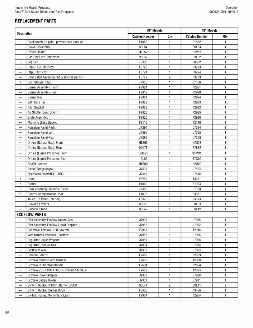
Operation 900636-00H, 10/2018
Innovative Hearth ProductsAltair™ DLX Series Direct-Vent Gas Fireplaces
66
REPLACEMENT PARTS
Description40” Models 45” Models
Catalog Number Qty Catalog Number Qty
--- Black touch-up paint, powder coat exterior F1882 1 F1882 1--- Blower Assembly 80L84 1 80L84 1--- Orifice Holder H7257 1 H7257 1--- Gas Flex Line Connector 93L32 1 93L32 13 Log Set J8300 1 J8302 1--- Base, Flue Restrictor F3723 1 F3723 1--- Flap, Restrictor F3724 1 F3724 1--- Door Latch Assembly Kit (2 latches per kit) F3789 2 F3789 24 Vent Stopper Plug J7356 1 J7356 15 Burner Assembly, Front F2921 1 F2921 1--- Burner Assembly, Rear F2919 1 F2920 1--- Burner Rod F2924 1 F2924 1--- 3/8” Flare Tee F2923 1 F2923 1--- Pilot Bracket F2922 1 F2922 1--- Air Shutter Control Arm F2925 1 F2925 1--- Grate Assembly F2926 1 F2926 1--- Manning Glass Gasket F2116 1 F2116 1--- Porcelain Panel Right J7394 1 J7394 1--- Porcelain Panel Left J7395 1 J7395 1--- Porcelain Panel Rear J7396 1 J7398 1--- Orifice (Natural Gas), Front H8303 1 H4873 1--- Orifice (Natural Gas), Rear 99K76 1 37L82 1
--- Orifice (Liquid Propane), Front 35M91 1 35M91 1
--- Orifice (Liquid Propane), Rear 19L52 1 37G00 1--- On/Off Jumper H8809 1 H8809 1--- Astria® Badge (logo) J7593 1 J7593 1--- Fiberboard Standoff 4” - RNC J7440 1 J7448 17 Hood F3260 1 F3261 18 Barrier F1840 1 F1903 19 Door Assembly, Ceramic Glass J7389 1 J7390 110 Control Compartment Door F1836 1 F3631 1--- Touch-Up Paint (Interior) F3373 1 F3373 1--- Glowing Embers 88L53 1 88L53 1--- Volcanic Stone 80L42 1 80L42 1
ECOFLOW PARTS--- Pilot Assembly, Ecoflow, Natural Gas J7935 1 J7935 1--- Pilot Assembly, Ecoflow, Liquid Propane J7962 1 J7962 1--- Gas Valve, Ecoflow, .120” low rate F2918 1 F2918 1--- Wire harness Traditional, Ecoflow J7956 1 J7956 1--- Regulator, Liquid Propane J7958 1 J7958 1--- Regulator, Natural Gas J7934 1 J7934 1--- Ecoflow V Wire J7933 1 J7933 1--- Remote Control F2689 1 F2689 1--- Ecoflow Remote wire harness F2690 1 F2690 1--- Ecoflow RF Control Module F2694 1 F2694 1--- Ecoflow VCS-ECOEXTMOD Extension Module F2693 1 F2693 1--- Ecoflow Power Adaptor J7930 1 J7930 1--- Ecoflow Battery Holder J7931 1 J7931 1 --- Switch, Rocker, IPI/CPI, Burner On/Off 80L41 2 80L41 2--- Switch, Rocker, Burner Hi/Lo F3456 1 F3456 1--- Switch, Rocker, Momentary, Learn F2964 1 F2964 1
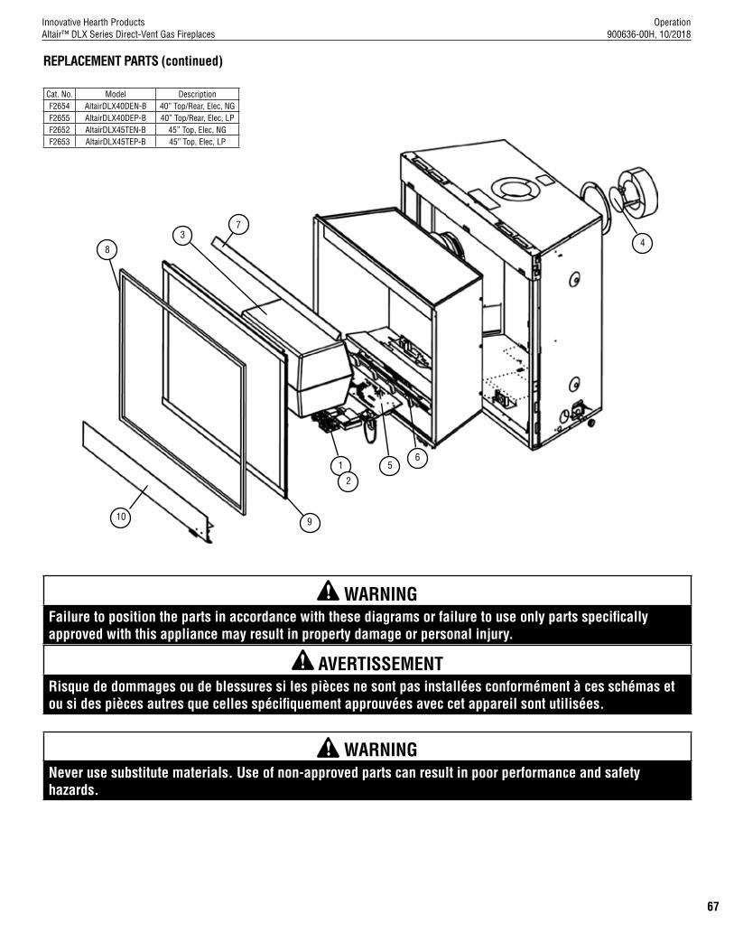
Operation 900636-00H, 10/2018
Innovative Hearth ProductsAltair™ DLX Series Direct-Vent Gas Fireplaces
67
WARNING Never use substitute materials. Use of non-approved parts can result in poor performance and safety hazards.
37
1
2
48
910
65
REPLACEMENT PARTS (continued)
WARNING Failure to position the parts in accordance with these diagrams or failure to use only parts specifically approved with this appliance may result in property damage or personal injury.
AVERTISSEMENT Risque de dommages ou de blessures si les pièces ne sont pas installées conformément à ces schémas et ou si des pièces autres que celles spécifiquement approuvées avec cet appareil sont utilisées.
Cat. No. Model DescriptionF2654 AltairDLX40DEN-B 40” Top/Rear, Elec, NGF2655 AltairDLX40DEP-B 40” Top/Rear, Elec, LPF2652 AltairDLX45TEN-B 45” Top, Elec, NGF2653 AltairDLX45TEP-B 45” Top, Elec, LP

Operation 900636-00H, 10/2018
Innovative Hearth ProductsAltair™ DLX Series Direct-Vent Gas Fireplaces
68
NOTES______________________________________________________________________________________________________________________________________________________________________________________________________________________________________________________________________________________________________________________________________________________________________________________________________________________________________________________________________________________________________________________________________________________________________________________________________________________________________________________________________________________________________________________________________________________________________________________________________________________________________________________________________________________________________________________________________________________________________________________________________________________________________________________________________________________________________________________________________________________________________________________________________________________________________________________________________________________________________________________________________________________________________________________________________________________________________________________________________________________________________________________________________________________________________________________________________________________________________________________________________________________________________________________________________________________________________________________________________________________________________________________________________________________________________________________________________________________________________________________________________________________________________________________________________________
NOTES

69Printed in U.S.A. © 2013 Innovative Hearth Products
P/N 900199-00, Rev. C 02/2018Innovative Hearth Products1769 East Lawrence Street • Russellville, AL 35654
Innovative Hearth ProductsAstria® Brand Gas FireplaceLimited Lifetime Warranty
THE WARRANTYInnovative Hearth Products ("IHP") Limited Lifetime Warranty warrants your Astria® brand gas fireplace ("Product") to be free from defects in materials and workmanship at the time of manufacture. The product body, firebox and barrier carry the Limited Lifetime Warranty. Ceramic glass carries the Limited Lifetime Warranty against thermal breakage only. After installation, if covered components manufactured by IHP are found to be defective in materials or workmanship during the Limited Lifetime Warranty period and while the Product remains at the site of the original installation, IHP will, at its option, repair or replace the covered components. If repair or replacement is not commercially practical, IHP will, at its option, refund the purchase price or wholesale price of the IHP product, whichever is applicable. IHP will also pay IHP prevailing labor rates, as determined in its sole discretion, incurred in repairing or replacing such components for up to five years. THERE ARE EXCLUSIONS AND LIMITATIONS to this Limited Lifetime Warranty as described herein.
COVERAGE COMMENCEMENT DATEWarranty coverage begins on the date of purchase. In the case of new home construction, warranty coverage begins on the date of first occupancy of the dwelling or six months after the sale of the Product by an independent IHP dealer/distributor, whichever occurs earlier. The warranty shall commence no later than 24 months following the date of product shipment from IHP, regardless of the installation or occupancy date.
EXCLUSIONS AND LIMITATIONSThis Limited Lifetime Warranty applies only if the Product is installed in the United States or Canada and only if operated and maintained in accordance with the printed instructions accompanying the Product and in compliance with all applicable installation and building codes and good trade practices.
This warranty is non-transferable and extends to the original owner only. The Product must be purchased through a listed supplier of IHP and proof of purchase must be provided. The product body, firebox and barrier carry the Limited Lifetime Warranty from the date of installation. Vent components, trim components and paint are excluded from this Limited Lifetime Warranty. The following do not carry the Limited Lifetime Warranty but are warranted as follows:
Burner – Repair or replacement for five years from the date of installationGas components & electrical components – Repair or replacement for one year from the date of installationGaskets – Repair or replacement for one year from the date of installationGold & nickel plating - Replacement for two years from date of installation. Excludes tarnishing Labor coverage – Prevailing IHP labor rates apply for the warranty period of the component Light bulbs & batteries – Replacement for 90 days from the date of installationLogs – Replacement for five years from the date of installation against thermal breakage onlyOptional blowers & remote controls – Repair or replacement for one year from the date of installationOptional glass doors & optional glass accessories – Repair or replacement for 90 days from the date of installationOptional surrounds – Stone/Natural Materials: Replacement for one year against cracking or breakage due to thermal stress. Other Materials: Replacement for one year. Excludes surface and hairline cracks and scratches or slight color changes that do not affect the operation or safety of the unitTempered Glass -Replacement for one year from the date of installation
Parts not otherwise listed carry a 90 day warranty from the date of installation.
Whenever practicable, IHP will provide replacement parts, if available, for a period of 10 years from the last date of manufacture of the Product.
IHP will not be responsible for: (a) damages caused by normal wear and tear, accident, riot, fire, flood or acts of God; (b) damages caused by abuse, negligence, misuse, or unauthorized alteration or repair of the Product affecting its stability or performance (The Product must be subjected to normal use. The Product is designed to burn either natural or propane gas only. Burning conventional fuels such as wood, coal or any other solid fuel will cause damage to the Product, will produce excessive temperatures and could result in a fire hazard.); (c) damages caused by failing to provide proper maintenance and service in accordance with the instructions provided with the Product; (d) damages, repairs or inefficiency resulting from faulty installation or application of the Product.
IHP is not responsible for inadequate fireplace system draft caused by air conditioning and heating systems, mechanical ventilation systems, or general construction conditions which may generate negative pressure in the room in which the appliance is installed. Additionally IHP assumes no responsibility for drafting conditions caused by venting configurations, adjoining trees or buildings, adverse wind conditions or unusual environmental factors and conditions that affect the operation of the unit.
This Limited Lifetime Warranty covers only parts and labor as provided herein. In no case shall IHP be responsible for materials, components or construction, which are not manufactured or supplied by IHP or for the labor necessary to install, repair or remove such materials, components or construction. Additional utility bills incurred due to any malfunction or defect in equipment are not covered by this warranty. All replacement or repair components will be shipped F.O.B. from the nearest stocking IHP factory.
LIMITATION ON LIABILITYIt is expressly agreed and understood that IHP’s sole obligation and the purchaser’s exclusive remedy under this warranty, under any other warranty, expressed or implied, or in contract, tort or otherwise, shall be limited to replacement, repair, or refund, as specified herein.
In no event shall IHP be liable for any incidental or consequential damages caused by defects in the Product, whether such damage occurs or is discovered before or after repair or replacement, and whether such damage is caused by IHP’s negligence. IHP has not made and does not make any representation or warranty of fitness for a particular use or purpose, and there is no implied condition of fitness for a particular use or purpose.
IHP makes no expressed warranties except as stated in this Limited Lifetime Warranty. The duration of any implied warranty is limited to the duration of this expressed warranty.
No one is authorized to change this Limited Lifetime Warranty or to create for IHP any other obligation or liability in connection with the Product. Some states and provinces do not allow the exclusion or limitation of incidental or consequential damages, so the above limitations or exclusions may not apply to you. The provisions of this Limited Lifetime Warranty are in addition to and not a modification of or subtraction from any statutory warranties and other rights and remedies provided by law.
INVESTIGATION OF CLAIMS AGAINST WARRANTYIHP reserves the right to investigate any and all claims against this Limited Lifetime Warranty and to decide, in its sole discretion, upon the method of settlement.
To receive the benefits and advantages described in this Limited Lifetime Warranty, the appliance must be installed and repaired by a licensed contractor approved by IHP.
Contact IHP at the address provided herein to obtain a listing of approved dealers/distributors. IHP shall in no event be responsible for any warranty work done by a contractor that is not approved without first obtaining IHP's prior written consent.
HOW TO REGISTER A CLAIM AGAINST WARRANTYIn order for any claim under this warranty to be valid, you must contact the IHP dealer/distributor from which you purchased the product. If you cannot locate the dealer/distributor, then you must notify IHP in writing. IHP must be notified of the claimed defect in writing within 90 days of the date of failure. Notices should be directed to the IHP Warranty Department at 1769 East Lawrence Street; Russellville, AL 35654 or visit our website at WWW.ASTRIA.US.COM.

Installation and Operation Instructions900636-00H, 10/2018
Innovative Hearth ProductsAltair™ DLX Series Direct-Vent Gas Fireplaces
Astria.us.comRecord the following important information about your fireplace:
Fireplace model number
Fireplace serial number
Date fireplace was Installed
Type of gas fireplace uses
Dealer name
Innovative Hearth Products (IHP) reserves the right to make changes at any time, without notice, in design, materials, specifications, prices and also to discontinue colors, styles and products. Consult your local distributor for fireplace code information.
Printed in U.S.A. © 2016 Innovative Hearth ProductsP/N 900636-00 Rev. H 10/2018 1769 East Lawrence Street • Russellville, AL 35654
P900636-00