Embed Size (px)
Citation preview
Form 43471000
Dec 2017
INSTALLATION AND OPERATION INSTRUCTIONS
OWNER / INSTALLER: For your safety this manual must be carefully and thoroughly read and
understood before installing, operating or servicing this heater.
COLD BLOCKER
INFRARED RADIANT TUBE HEATER Single and Two Stage Pull Through System (Negative Pressure)
Models: CB20, CB30, CB40, CB50 – (N5/L5)
CB40, CB50 – (N7/L7)
!INSTALLER: This manual is the property of the owner. Please present this manual to the
owner when you leave the job site.
▲WARNING: Improper installation, adjustment, alteration, service, or maintenance can
cause property damage, injury or death. Read the installation, operation and maintenance
instructions thoroughly before installing or servicing this equipment.
IF YOU SMELL GAS: FOR YOUR SAFETY
! DO NOT try to light any appliance.
! DO NOT touch any electrical switch; DO NOT use any
telephone in your building.
! IMMEDIATELY call your gas supplier from a neighbor's
telephone. Follow the gas supplier's instructions. If you
cannot reach your gas supplier, call the fire department.
DO NOT store or use gasoline or other
flammable vapors and liquids in the vicinity of
this or any other appliance.
!IMPORTANT: SAVE THIS MANUAL FOR FUTURE REFERENCE.
SPACE-RAY Post Office Box 36485 (28236) • 305 Doggett Street (28203) • Charlotte, North Carolina
Phone (704) 372-6391 • Fax (704) 332-5843 • www.spaceray.com • email: [email protected]
Form 43471000
Dec 2017 -1-
TABLE OF CONTENTS
SECTION DESCRIPTION PAGE
1.0) Safety ................................................................................................................................................... 2 2.0) Installer Responsibility ...................................................................................................................... 2 3.0) General Information ........................................................................................................................... 2 4.0) Minimum Clearances to Combustibles ........................................................................................... 4 5.0) Specifications...................................................................................................................................... 5 6.0) Packing List ......................................................................................................................................... 5 6.1) Accessory Packages .......................................................................................................................... 6 7.0) Dimensions – CB Series .................................................................................................................... 8 8.0) Heater Assembly Overview ............................................................................................................... 9 9.0) Typical Suspension Methods .......................................................................................................... 10 10.0) Heater Assembly .............................................................................................................................. 11 11.0) Gas Connections and Regulations ................................................................................................. 14 12.0) Instructions for Pressure Test Gauge Connection ....................................................................... 16 13.0) Electrical Connections ..................................................................................................................... 18 13.1) Single Stage (N5/L5) – Internal and Thermostat Connections ................................................ 18 13.2) Two Stage (N7/L7) – Internal and Thermostat Connections .................................................... 21 14.0) Venting ............................................................................................................................................... 25 15.0) Air for Combustion ........................................................................................................................... 30 15.1) Direct Outside Air for Combustion ................................................................................................. 30 16.0) Lighting and Shutdown Instructions .............................................................................................. 32 17.0) Sequence of Operation – Single Stage (N5/L5) .......................................................................... 32
17.1) Sequence of Operation – Two Stage (N7/L7) .............................................................................. 32
18.0) Control Component Location .......................................................................................................... 34 19.0) Cleaning and Annual Maintenance ............................................................................................... 35 20.0) Troubleshooting Guide – Single Stage (N5/L5) .......................................................................... 36 20.1) Troubleshooting Guide – Two Stage (N7/L7) .............................................................................. 39 21.0) Replacing Parts ................................................................................................................................ 43 21.1) Removal of Spark Electrode ........................................................................................................... 43 21.2) Removing Main Burner and Gas Valve ......................................................................................... 44 21.3) Air Switch Pressure Check .............................................................................................................. 44 21.4) Ignition System Checks ................................................................................................................... 45 21.5) Motor and Blower Wheel Check ..................................................................................................... 46 22.0) Installation Data ............................................................................................................................... 46 23.0) Replacement Parts Guide ............................................................................................................... 47 24.0) Warnings Card .................................................................................................................................. 51
This heater complies with ANSI Z83.20 (current standard) and CSA 2.34. Copies of the National Fuel Gas Code (ANSI
Z223.1-latest edition) are available from the CSA at 8501 East Pleasant Valley Road, Cleveland, Ohio 44131 or 55 Scarsdale
Road, Don Mills, Ontario M3B 2R3. All NFPA codes are available from the National Fire Protection Association, Batterymarch
Park, Quincy, Massachusetts 02269.
For installations with mounting heights less than 10 feet, install the
heater at the highest possible height for the best radiant energy
distribution.
This product can expose you to chemicals including ceramic fibers, which
are known to the State of California to cause cancer, and carbon monoxide,
which is known to the State of California to cause birth defects or other
reproductive harm. For more information go to www.p65warnings.ca.gov.
Form 43471000
-2- Dec 2017
1.0) SAFETY
This heater is a self-contained infrared radiant tube heater. Safety information required during installation and
operation of this heater is provided in this manual and the labels on the product. The installation, service and
maintenance of this heater must be performed by a contractor qualified in the installation and service of gas
fired heating equipment.
All personnel in contact with the heater must read and understand all safety information, instructions and labels
before operation. The following symbols will be used in this manual to indicate important safety information.
SAFETY REQUIREMENTS
The heater area must be kept clear and free from combustible materials, gasoline and other flammable
vapors and liquids.
This heater is designed for use with one type of gas (LPG or Natural). Make sure that the type of gas to be
supplied to this heater matches that shown on the heater rating plate.
DO NOT install this heater directly onto an LPG container or propane cylinder without directions from your
propane company. LPG containers (propane cylinders) must not be stored indoors or in the vicinity of any
gas-burning appliance.
Children and adults should be alerted to the hazards of high surface temperatures and should stay away to
avoid burns or clothing ignition.
Clothing or other flammable materials should not be hung from the heater or placed on or near the heater.
Young children should be carefully supervised when they are in the same space as the heater.
NEVER attempt to service the heater while it is plugged in, operating or hot. Any guard or other protective
device removed for servicing a heater must be replaced prior to operating the heater.
Warning instructions must be followed to prevent or avoid hazards which
may cause serious injury, property damage or death.
Caution instructions must be followed to prevent incorrect operation or
installation of the heater which may cause minor injury or property
damage.
2.0) INSTALLER RESPONSIBILITY
The installer is responsible for the following:
The heater and venting, as well as electrical and gas supplies must be installed in accordance with these
installation instructions and any applicable codes and regulations.
Every heater shall be located with respect to building construction and other equipment so as to permit
access to the heater.
Each installer must follow the clearances to combustible materials for the heaters.
Install the heater so that the supports and hangers are correctly spaced in accordance with these
instructions. The heater must be supported by materials having a working load limit of at least 115lbs.
Supply the owner with a copy of these Installation and Operation Instructions.
Where unvented heaters are used, gravity or mechanical means shall be provided to supply and exhaust at
least 4 CFM per 1,000 Btu/hr input of installed heaters.
Never use the heater as a support for a ladder or other access equipment. Do not hang anything from the
heater.
Supply all installation materials necessary that are not included with the heater.
Check the nameplate to make sure that the burner is correct for the gas type in the building and the
installation altitude.
3.0) GENERAL INFORMATION
This heater is a self-contained infrared radiant tube heater for use in locations where flammable gases or vapors
are not generally present (as defined by OSHA acceptable limits) and is intended for space heating of garages,
vestibules and entry ways, workshops, enclosed patios, golf practice ranges and most industrial and commercial
applications. DO NOT install this heater in residential bedrooms or bathrooms, mobile homes or recreational
vehicles.
Form 43471000
Dec 2017 -3-
INSTALLATION REQUIREMENTS
The installation must conform to local building codes or in the absence of local codes, with the National Fuel Gas
Code ANSI Z223.1/NFPA54 or the Natural Gas and Propane Installation Code CSA B149.1. Heaters shall be
installed by a licensed contractor or licensed installer. Clearances to combustibles as outlined in this manual
should always be observed. In areas used for storage of combustible materials where they may be stacked
below the heater, NFPA54 requires that the installer must post signs that will “specify the maximum permissible
stacking height to maintain the required clearances from the heater to combustibles.”
Every heater shall be located with respect to building construction and other equipment so as to permit access
to the heater. Each installer shall use quality installation practices when locating the heater and must give
consideration to clearances to combustible materials, vehicles parked below, lights, overhead doors, storage
areas with stacked materials, sprinkler heads, gas and electrical lines and any other possible obstructions or
hazards. Consideration also must be given to service accessibility.
The heater, when installed without the Lower Mounting Height Kit (Part #43515000), MUST NOT BE MOUNTED
LOWER THAN 8 FT. above the finished floor. When the heater is installed with the Lower Mounting Height Kit
(this kit consists of the Emitter Guard Kit and the Draft Inducer Guard Kit), it MUST NOT BE MOUNTED LOWER
THAN 6 FT. above the finished floor. For installations above 8 ft., the Lower Mounting Height Kit is not required,
but the Emitter Guard Kit (Part #43485000) may be used for decorative purposes if desired. For installat ion of
these kits, refer to the separate installation instructions packaged in each kit.
The heater, when installed in aircraft hangars and public garages, must be installed in accordance with
ANSI/NFPA 409-latest edition (Standard for Aircraft Hangars), ANSI/NFPA 88a-latest edition (Standard for
Parking Structures), and ANSI/NFPA 88b-latest edition (Standard for Repair Garages) with the following
clearances:
a. At least 10 feet above the upper surfaces of wings or engine enclosures of the highest aircraft that may be
housed in the hangar and at least 8 feet above the floor in shops, offices, and other sections of hangars
communicating with aircraft storage or service areas.
b. At least 8 feet above the floor in public garages. ▲WARNING: Minimum clearances marked on the heater
must be maintained from vehicles parked below the heater.
(FOR CANADA ONLY)
a. Installation of this appliance is to be in accordance with latest edition of CSA B149.1 (Natural Gas and
Propane Installation Code).
b. For installation in public garages or aircraft hangars, the minimum clearances from the bottom of the
infrared heater to the upper surface of the highest aircraft or vehicle shall be 50 percent greater than the
certified minimum clearance, but the clearance shall not be less than 8 feet.
Although these heaters may be used in many applications other than space heating (e.g., process heating),
Space-Ray will not recognize the warranty for any use other than space heating.
This heater is for Indoor Installation and Covered Patio Installation only and can be used in either Vented or
Unvented mode. The term Unvented actually means Indirect Vented. While the products of combustion are
expelled into the building, national codes require ventilation in the building to dilute these products of
combustion. This ventilation may be provided by gravity or mechanical means.
This heater is not an explosion proof heater. Where the possibility of exposure to volatile and low flash point
materials exists, it could result in property damage or death. This heater must not be installed in a spray booth
where the heater can operate during the spraying process. Consult your local fire marshal or insurance company.
High Altitude:
Appliances are supplied as standard for altitudes of O to 2,000 feet (0-610 m). High-altitude ratings are obtained
by a change in the orifice size. When ordered for high altitude installations, burners are supplied by the factory
ready for high altitude installation. Check the nameplate for altitude before proceeding with the installation. In
Canada the adjustment for altitude is made in accordance with Standard CGA 2.17, Gas-Fired Appliances for Use
at High Altitudes.
Form 43471000
-4- Dec 2017
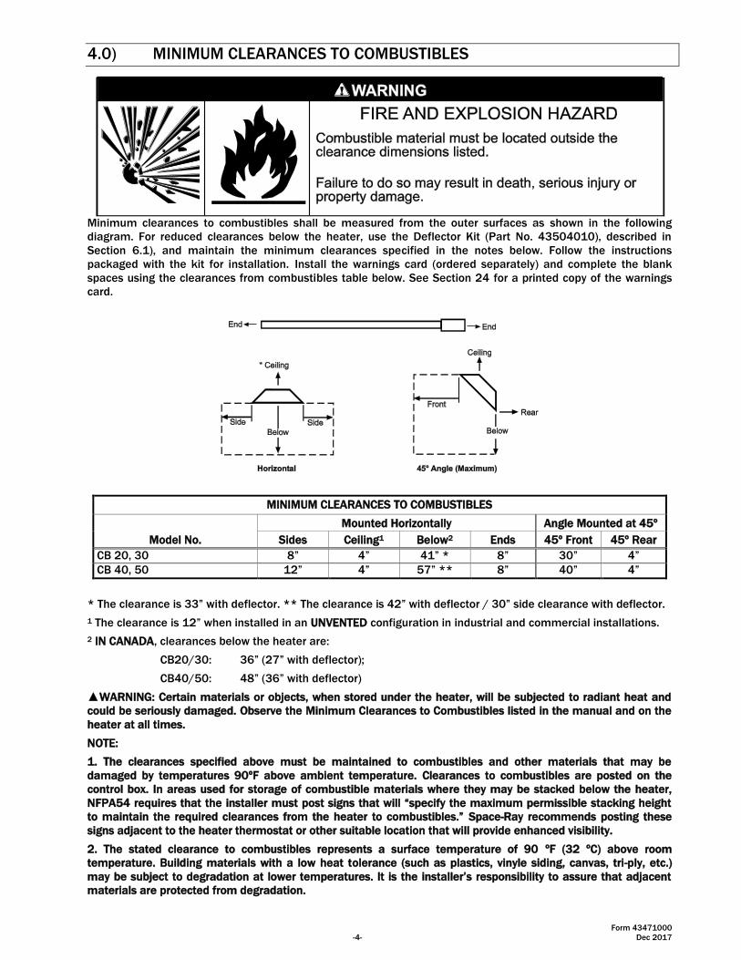
4.0) MINIMUM CLEARANCES TO COMBUSTIBLES
Minimum clearances to combustibles shall be measured from the outer surfaces as shown in the following
diagram. For reduced clearances below the heater, use the Deflector Kit (Part No. 43504010), described in
Section 6.1), and maintain the minimum clearances specified in the notes below. Follow the instructions
packaged with the kit for installation. Install the warnings card (ordered separately) and complete the blank
spaces using the clearances from combustibles table below. See Section 24 for a printed copy of the warnings
card.
MINIMUM CLEARANCES TO COMBUSTIBLES
Model No.
Mounted Horizontally Angle Mounted at 45º
Sides Ceiling1 Below2 Ends 45º Front 45º Rear
CB 20, 30 8” 4” 41” * 8” 30” 4”
CB 40, 50 12” 4” 57” ** 8” 40” 4”
* The clearance is 33” with deflector. ** The clearance is 42” with deflector / 30” side clearance with deflector.
1 The clearance is 12” when installed in an UNVENTED configuration in industrial and commercial installations.
2 IN CANADA, clearances below the heater are:
CB20/30: 36” (27” with deflector);
CB40/50: 48” (36” with deflector)
▲WARNING: Certain materials or objects, when stored under the heater, will be subjected to radiant heat and
could be seriously damaged. Observe the Minimum Clearances to Combustibles listed in the manual and on the
heater at all times.
NOTE:
1. The clearances specified above must be maintained to combustibles and other materials that may be
damaged by temperatures 90ºF above ambient temperature. Clearances to combustibles are posted on the
control box. In areas used for storage of combustible materials where they may be stacked below the heater,
NFPA54 requires that the installer must post signs that will “specify the maximum permissible stacking height
to maintain the required clearances from the heater to combustibles.” Space-Ray recommends posting these
signs adjacent to the heater thermostat or other suitable location that will provide enhanced visibility.
2. The stated clearance to combustibles represents a surface temperature of 90 ºF (32 ºC) above room
temperature. Building materials with a low heat tolerance (such as plastics, vinyle siding, canvas, tri-ply, etc.)
may be subject to degradation at lower temperatures. It is the installer’s responsibility to assure that adjacent
materials are protected from degradation.
Form 43471000
Dec 2017 -5-
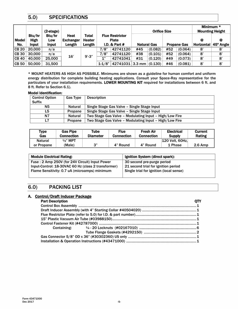
5.0) SPECIFICATIONS
Model
No.
Btu/hr
High
Input
(2-stage)
Btu/hr
Low
Input
Heat
Exchanger
Length
Total
Heater
Length
Flue Restrictor
Plate
I.D. & Part #
Orifice Size
Minimum *
Mounting Height
Natural Gas Propane Gas
@
Horizontal
@
45º Angle
CB 20 20,000 n/a
16’ 9’-3”
7/8” 42741120 #45 (0.082) #52 (0.064) 8’ 8’
CB 30 30,000 n/a 7/8” 42741120 #38 (0.101) #52 (0.064) 8’ 8’
CB 40 40,000 25,000 1” 42741041 #31 (0.120) #49 (0.073) 8’ 8’
CB 50 50,000 31,500 1-1/8” 42741031 3.3 mm (0.130) #46 (0.081) 8’ 8’
* MOUNT HEATERS AS HIGH AS POSSIBLE. Minimums are shown as a guideline for human comfort and uniform
energy distribution for complete building heating applications. Consult your Space-Ray representative for the
particulars of your installation requirements. LOWER MOUNTING KIT required for installations between 6 ft. and
8 ft. Refer to Section 6.1).
Model Identification:
Control Option
Suffix
Gas Type Description
N5 Natural Single Stage Gas Valve – Single Stage Input
L5 Propane Single Stage Gas Valve – Single Stage Input
N7 Natural Two Stage Gas Valve – Modulating Input – High/Low Fire
L7 Propane Two Stage Gas Valve – Modulating Input – High/Low Fire
Type
Gas
Gas Pipe
Connection
Tube
Diameter
Flue
Connection
Fresh Air
Connection
Electrical
Supply
Current
Rating
Natural
or Propane
½” MPT
(Male) 3” 4” Round 4” Round
120 Volt, 60Hz,
1 Phase 2.6 Amp
Module Electrical Rating: Ignition System (direct spark):
Fuse : 2 Amp 250V (for 24V Circuit) Input Power
Input-Control: 18-30VAC 60 Hz (class 2 transformer)
Flame Sensitivity: 0.7 uA (microamps) minimum
30 second pre-purge period
21 second trial for ignition period
Single trial for ignition (local sense)
6.0) PACKING LIST
A. Control/Draft Inducer Package Part Description QTY
Control Box Assembly .............................................................................................................................. 1
Draft Inducer Assembly (with 4” Starting Collar #40504020) .......................................................... 1
Flue Restrictor Plate (refer to 5.0) for I.D. & part number) ................................................................. 1
15” Plastic Vacuum Air Tube (#03988150) .......................................................................................... 1
Control Fastener Kit (#42787000) ........................................................................................................ 1
Containing: ¼ - 20 Locknuts (#02167010) ............................................................. 6
Tube Flange Gaskets (#4292150) ........................................................ 2
Gas Connector 5/8” OD x 36” (#30302360) US only ......................................................................... 1
Installation & Operation Instructions (#43471000) ........................................................................... 1
Form 43471000
-6- Dec 2017
CONTROL/DRAFT INDUCER PACKAGE NUMBERS
1-STAGE CONTROLS 2-STAGE CONTROLS
MODEL NO. PART NO. GAS TYPE MODEL NO. PART NO. GAS TYPE
CB20-N5 43467010 NATURAL CB40-N7 43467550 NATURAL
CB30-N5 43467030 NATURAL CB50-N7 43467570 NATURAL
CB40-N5 43467050 NATURAL CB40-L7 43467560 PROPANE
CB50-N5 43467070 NATURAL CB50-L7 43467580 PROPANE
CB20-L5 43467020 PROPANE
CB30-L5 43467040 PROPANE
CB40-L5 43467060 PROPANE
CB50-L5 43467080 PROPANE
B. Body Package Descriptions
6.1) ACCESSORY PACKAGES
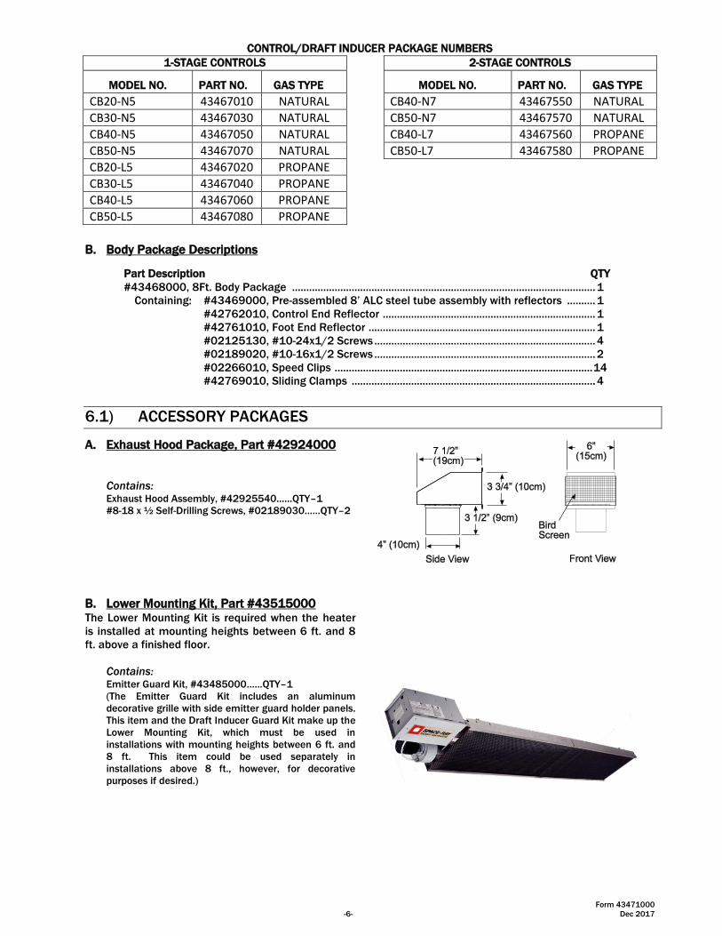
A. Exhaust Hood Package, Part #42924000
Contains: Exhaust Hood Assembly, #42925540……QTY–1
#8-18 x ½ Self-Drilling Screws, #02189030……QTY–2
B. Lower Mounting Kit, Part #43515000 The Lower Mounting Kit is required when the heater
is installed at mounting heights between 6 ft. and 8
ft. above a finished floor.
Contains: Emitter Guard Kit, #43485000……QTY–1
(The Emitter Guard Kit includes an aluminum
decorative grille with side emitter guard holder panels.
This item and the Draft Inducer Guard Kit make up the
Lower Mounting Kit, which must be used in
installations with mounting heights between 6 ft. and
8 ft. This item could be used separately in
installations above 8 ft., however, for decorative
purposes if desired.)
Part Description QTY
#43468000, 8Ft. Body Package ........................................................................................................... 1
Containing: #43469000, Pre-assembled 8’ ALC steel tube assembly with reflectors .......... 1
#42762010, Control End Reflector ........................................................................... 1
#42761010, Foot End Reflector ................................................................................ 1
#02125130, #10-24x1/2 Screws .............................................................................. 4
#02189020, #10-16x1/2 Screws .............................................................................. 2
#02266010, Speed Clips ........................................................................................... 14
#42769010, Sliding Clamps ...................................................................................... 4
Form 43471000
Dec 2017 -7-
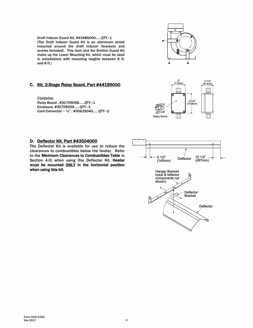
Draft Inducer Guard Kit, #43486000……QTY–1
(The Draft Inducer Guard Kit is an aluminum shield
mounted around the draft inducer (brackets and
screws included). This item and the Emitter Guard Kit
make up the Lower Mounting Kit, which must be used
in installations with mounting heights between 6 ft.
and 8 ft.)
C. Kit, 2-Stage Relay Board, Part #44195000
Contains: Relay Board , #30709058……QTY–1
Enclosure, #30709059……QTY–1
Cord Connector – ½” , #30635040……QTY–2
D. Deflector Kit, Part #43504000 The Deflector Kit is available for use to reduce the
clearances to combustibles below the heater. Refer
to the Minimum Clearances to Combustibles Table in
Section 4.0) when using this Deflector Kit. Heater
must be mounted ONLY in the horizontal position
when using this kit.
Form 43471000
-8- Dec 2017
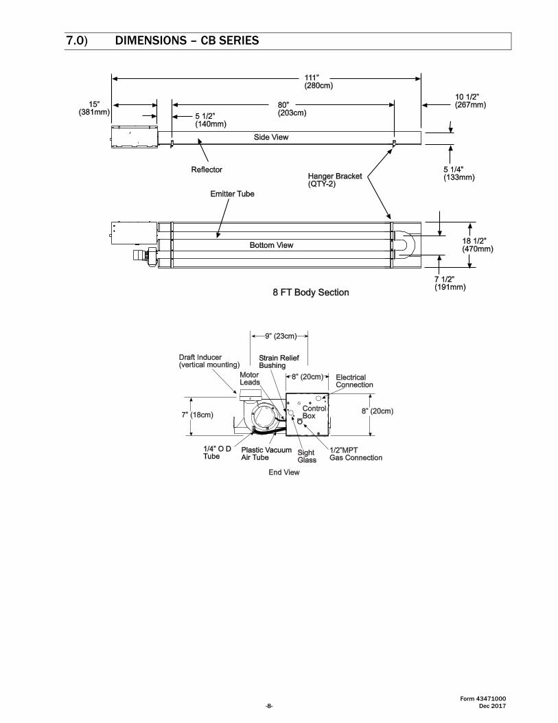
7.0) DIMENSIONS – CB SERIES

Form 43471000
Dec 2017 -9-
8.0) HEATER ASSEMBLY OVERVIEW
Form 43471000
-10- Dec 2017
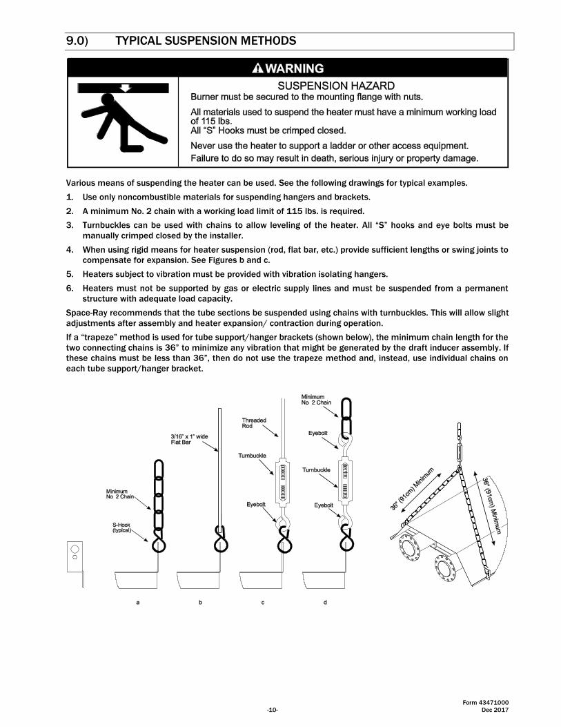
9.0) TYPICAL SUSPENSION METHODS
Various means of suspending the heater can be used. See the following drawings for typical examples.
1. Use only noncombustible materials for suspending hangers and brackets.
2. A minimum No. 2 chain with a working load limit of 115 lbs. is required.
3. Turnbuckles can be used with chains to allow leveling of the heater. All “S” hooks and eye bolts must be
manually crimped closed by the installer.
4. When using rigid means for heater suspension (rod, flat bar, etc.) provide sufficient lengths or swing joints to
compensate for expansion. See Figures b and c.
5. Heaters subject to vibration must be provided with vibration isolating hangers.
6. Heaters must not be supported by gas or electric supply lines and must be suspended from a permanent
structure with adequate load capacity.
Space-Ray recommends that the tube sections be suspended using chains with turnbuckles. This will allow slight
adjustments after assembly and heater expansion/ contraction during operation.
If a “trapeze” method is used for tube support/hanger brackets (shown below), the minimum chain length for the
two connecting chains is 36” to minimize any vibration that might be generated by the draft inducer assembly. If
these chains must be less than 36”, then do not use the trapeze method and, instead, use individual chains on
each tube support/hanger bracket.
Form 43471000
Dec 2017 -11-
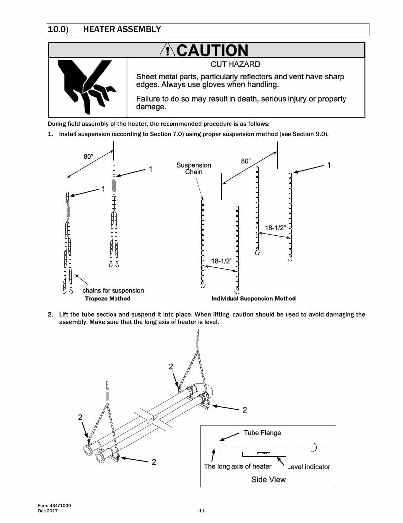
10.0) HEATER ASSEMBLY
During field assembly of the heater, the recommended procedure is as follows:
1. Install suspension (according to Section 7.0) using proper suspension method (see Section 9.0).
Trapeze Method Individual Suspension Method
2. Lift the tube section and suspend it into place. When lifting, caution should be used to avoid damaging the
assembly. Make sure that the long axis of heater is level.
Form 43471000
-12- Dec 2017
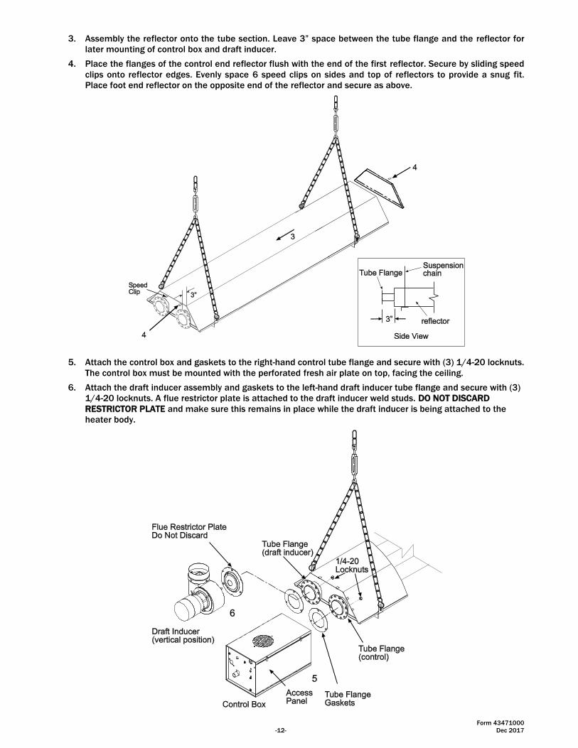
3. Assembly the reflector onto the tube section. Leave 3” space between the tube flange and the reflector for
later mounting of control box and draft inducer.
4. Place the flanges of the control end reflector flush with the end of the first reflector. Secure by sliding speed
clips onto reflector edges. Evenly space 6 speed clips on sides and top of reflectors to provide a snug fit.
Place foot end reflector on the opposite end of the reflector and secure as above.
5. Attach the control box and gaskets to the right-hand control tube flange and secure with (3) 1/4-20 locknuts.
The control box must be mounted with the perforated fresh air plate on top, facing the ceiling.
6. Attach the draft inducer assembly and gaskets to the left-hand draft inducer tube flange and secure with (3)
1/4-20 locknuts. A flue restrictor plate is attached to the draft inducer weld studs. DO NOT DISCARD
RESTRICTOR PLATE and make sure this remains in place while the draft inducer is being attached to the
heater body.
Form 43471000
Dec 2017 -13-
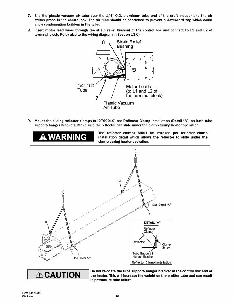
7. Slip the plastic vacuum air tube over the 1/4” O.D. aluminum tube end of the draft inducer and the air
switch probe in the control box. The air tube should be shortened to prevent a downward sag which could
allow condensation build-up in the tube.
8. Insert motor lead wires through the strain relief bushing of the control box and connect to L1 and L2 of
terminal block. Refer also to the wiring diagram in Section 13.0).
9. Mount the sliding reflector clamps (#42769010) per Reflector Clamp Installation (Detail “A”) on both tube
support/hanger brackets. Make sure the reflector can slide under the clamp during heater operation.
The reflector clamps MUST be installed per reflector clamp
installation detail which allows the reflector to slide under the
clamp during heater operation.
Do not relocate the tube support/hanger bracket at the control box end of
the heater. This will increase the weight on the emitter tube and can result
in premature tube failure.
Form 43471000
-14- Dec 2017
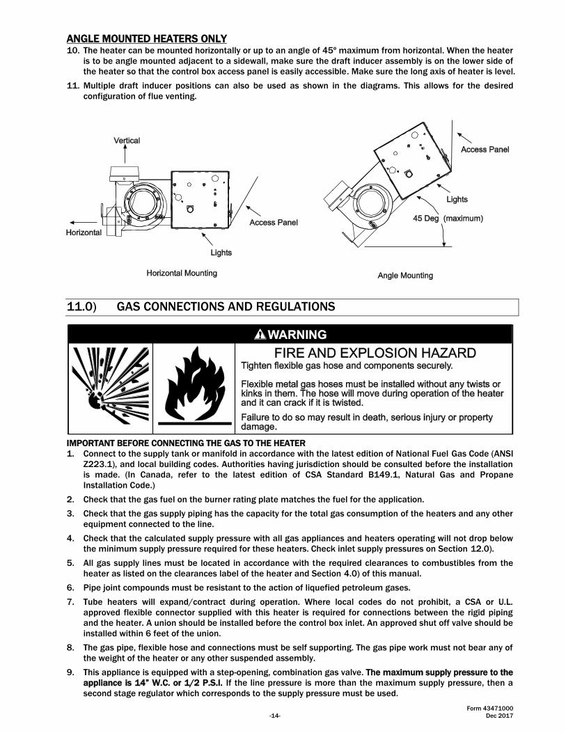
ANGLE MOUNTED HEATERS ONLY 10. The heater can be mounted horizontally or up to an angle of 45º maximum from horizontal. When the heater
is to be angle mounted adjacent to a sidewall, make sure the draft inducer assembly is on the lower side of
the heater so that the control box access panel is easily accessible. Make sure the long axis of heater is level.
11. Multiple draft inducer positions can also be used as shown in the diagrams. This allows for the desired
configuration of flue venting.
11.0) GAS CONNECTIONS AND REGULATIONS
IMPORTANT BEFORE CONNECTING THE GAS TO THE HEATER
1. Connect to the supply tank or manifold in accordance with the latest edition of National Fuel Gas Code (ANSI
Z223.1), and local building codes. Authorities having jurisdiction should be consulted before the installation
is made. (In Canada, refer to the latest edition of CSA Standard B149.1, Natural Gas and Propane
Installation Code.)
2. Check that the gas fuel on the burner rating plate matches the fuel for the application.
3. Check that the gas supply piping has the capacity for the total gas consumption of the heaters and any other
equipment connected to the line.
4. Check that the calculated supply pressure with all gas appliances and heaters operating will not drop below
the minimum supply pressure required for these heaters. Check inlet supply pressures on Section 12.0).
5. All gas supply lines must be located in accordance with the required clearances to combustibles from the
heater as listed on the clearances label of the heater and Section 4.0) of this manual.
6. Pipe joint compounds must be resistant to the action of liquefied petroleum gases.
7. Tube heaters will expand/contract during operation. Where local codes do not prohibit, a CSA or U.L.
approved flexible connector supplied with this heater is required for connections between the rigid piping
and the heater. A union should be installed before the control box inlet. An approved shut off valve should be
installed within 6 feet of the union.
8. The gas pipe, flexible hose and connections must be self supporting. The gas pipe work must not bear any of
the weight of the heater or any other suspended assembly.
9. This appliance is equipped with a step-opening, combination gas valve. The maximum supply pressure to the
appliance is 14” W.C. or 1/2 P.S.I. If the line pressure is more than the maximum supply pressure, then a
second stage regulator which corresponds to the supply pressure must be used.
Form 43471000
Dec 2017 -15-
10. After all gas connections have been made, make sure the heater and all gas outlets are turned off before
the main gas supply is turned on slowly. Turn the gas supply pressure on and check for leaks. To check for
leaks, check by one of the methods listed in Appendix D of the National Fuel Gas Code.
11. If a 2nd stage regulator is used, the ball valve down stream in the supply line must be closed when purging
the gas lines to prevent gas seeping through it. If initial gas pressure is higher than 14” w.c. the redundant
combination gas valve is designed to lock out. Pressure build-up in the supply lines prior to the heater must
be released before proper heater operation.
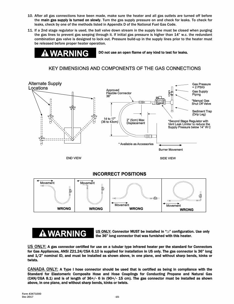
DO not use an open flame of any kind to test for leaks.
US ONLY: Connector MUST be installed in “” configuration. Use only
the 36” long connector that was furnished with this heater.
US ONLY: A gas connector certified for use on a tubular type infrared heater per the standard for Connectors
for Gas Appliances, ANSI Z21.24/CSA 6.10 is supplied for installation in US only. The gas connector is 36” long
and 1/2” nominal ID, and must be installed as shown above, in one plane, and without sharp bends, kinks or
twists.
CANADA ONLY: A Type I hose connector should be used that is certified as being in compliance with the
Standard for Elastomeric Composite Hose and Hose Couplings for Conducting Propane and Natural Gas
(CAN/CGA 8.1) and is of length of 36+/- 6 in (90+/- 15 cm). The gas connector must be installed as shown
above, in one plane, and without sharp bends, kinks or twists.
Form 43471000
-16- Dec 2017
12.0) INSTRUCTIONS FOR PRESSURE TEST GAUGE CONNECTION
SUPPLY PRESSURE
1. The installer will provide a 1/8” N.P.T. tapped plug, accessible for test gauge connection immediately
upstream of the gas supply connection to the heater.
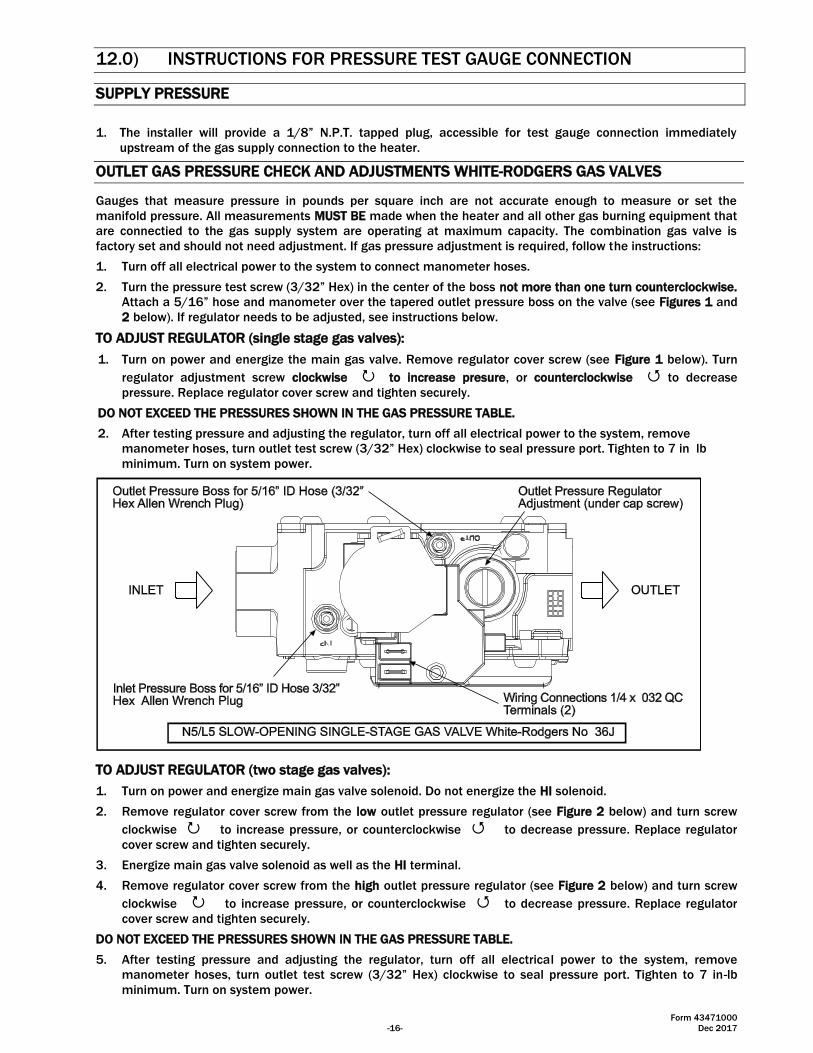
OUTLET GAS PRESSURE CHECK AND ADJUSTMENTS WHITE-RODGERS GAS VALVES
Gauges that measure pressure in pounds per square inch are not accurate enough to measure or set the
manifold pressure. All measurements MUST BE made when the heater and all other gas burning equipment that
are connectied to the gas supply system are operating at maximum capacity. The combination gas valve is
factory set and should not need adjustment. If gas pressure adjustment is required, follow the instructions:
1. Turn off all electrical power to the system to connect manometer hoses.
2. Turn the pressure test screw (3/32” Hex) in the center of the boss not more than one turn counterclockwise.
Attach a 5/16” hose and manometer over the tapered outlet pressure boss on the valve (see Figures 1 and
2 below). If regulator needs to be adjusted, see instructions below.
TO ADJUST REGULATOR (single stage gas valves):
1. Turn on power and energize the main gas valve. Remove regulator cover screw (see Figure 1 below). Turn
regulator adjustment screw clockwise to increase presure, or counterclockwise to decrease
pressure. Replace regulator cover screw and tighten securely.
DO NOT EXCEED THE PRESSURES SHOWN IN THE GAS PRESSURE TABLE.
2. After testing pressure and adjusting the regulator, turn off all electrical power to the system, remove
manometer hoses, turn outlet test screw (3/32” Hex) clockwise to seal pressure port. Tighten to 7 in lb
minimum. Turn on system power.
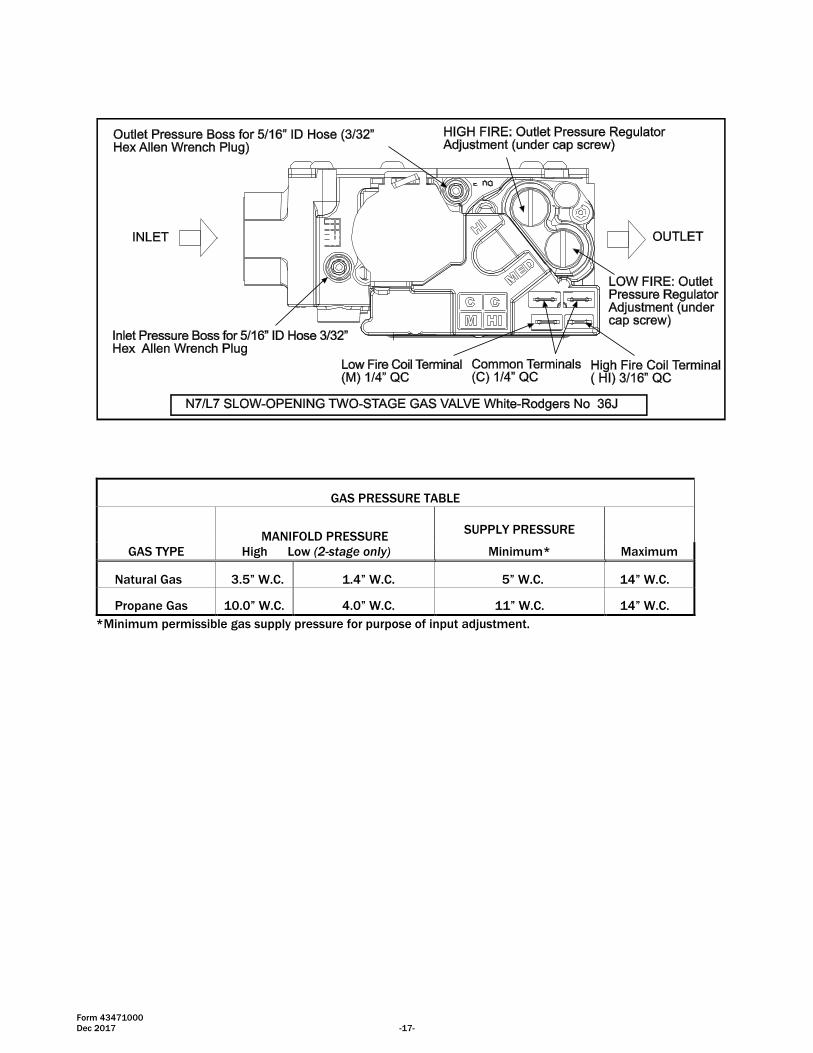
TO ADJUST REGULATOR (two stage gas valves):
1. Turn on power and energize main gas valve solenoid. Do not energize the HI solenoid.
2. Remove regulator cover screw from the low outlet pressure regulator (see Figure 2 below) and turn screw
clockwise to increase pressure, or counterclockwise to decrease pressure. Replace regulator
cover screw and tighten securely.
3. Energize main gas valve solenoid as well as the HI terminal.
4. Remove regulator cover screw from the high outlet pressure regulator (see Figure 2 below) and turn screw
clockwise to increase pressure, or counterclockwise to decrease pressure. Replace regulator
cover screw and tighten securely.
DO NOT EXCEED THE PRESSURES SHOWN IN THE GAS PRESSURE TABLE.
5. After testing pressure and adjusting the regulator, turn off all electrical power to the system, remove
manometer hoses, turn outlet test screw (3/32” Hex) clockwise to seal pressure port. Tighten to 7 in-lb
minimum. Turn on system power.
Form 43471000
Dec 2017 -17-
*Minimum permissible gas supply pressure for purpose of input adjustment.
GAS PRESSURE TABLE
GAS TYPE
MANIFOLD PRESSURE
High Low (2-stage only)
SUPPLY PRESSURE
Minimum* Maximum
Natural Gas 3.5” W.C. 1.4” W.C. 5” W.C. 14” W.C.
Propane Gas 10.0” W.C. 4.0” W.C. 11” W.C. 14” W.C.
Form 43471000
-18- Dec 2017
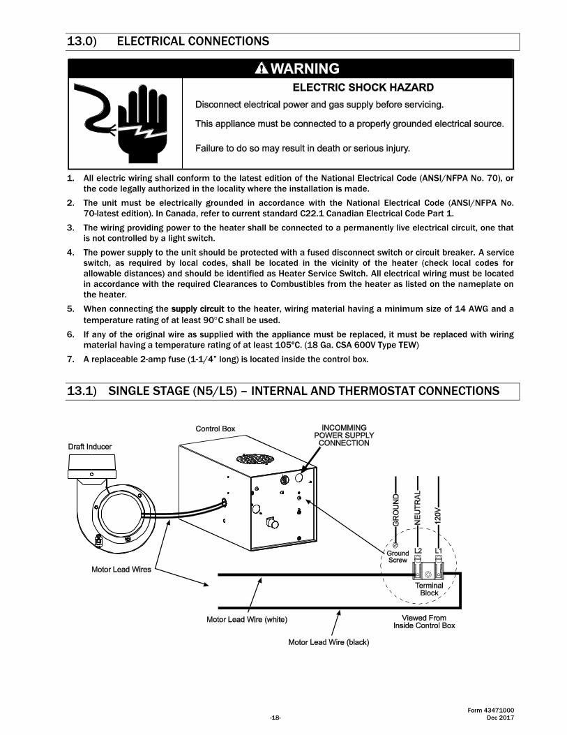
13.0) ELECTRICAL CONNECTIONS
1. All electric wiring shall conform to the latest edition of the National Electrical Code (ANSI/NFPA No. 70), or
the code legally authorized in the locality where the installation is made.
2. The unit must be electrically grounded in accordance with the National Electrical Code (ANSI/NFPA No.
70-latest edition). In Canada, refer to current standard C22.1 Canadian Electrical Code Part 1.
3. The wiring providing power to the heater shall be connected to a permanently live electrical circuit, one that
is not controlled by a light switch.
4. The power supply to the unit should be protected with a fused disconnect switch or circuit breaker. A service
switch, as required by local codes, shall be located in the vicinity of the heater (check local codes for
allowable distances) and should be identified as Heater Service Switch. All electrical wiring must be located
in accordance with the required Clearances to Combustibles from the heater as listed on the nameplate on
the heater.
5. When connecting the supply circuit to the heater, wiring material having a minimum size of 14 AWG and a
temperature rating of at least 90C shall be used.
6. If any of the original wire as supplied with the appliance must be replaced, it must be replaced with wiring
material having a temperature rating of at least 105ºC. (18 Ga. CSA 600V Type TEW)
7. A replaceable 2-amp fuse (1-1/4” long) is located inside the control box.
13.1) SINGLE STAGE (N5/L5) – INTERNAL AND THERMOSTAT CONNECTIONS
Form 43471000
Dec 2017 -19-
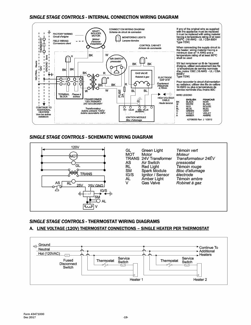
SINGLE STAGE CONTROLS - INTERNAL CONNECTION WIRING DIAGRAM
SINGLE STAGE CONTROLS - SCHEMATIC WIRING DIAGRAM
SINGLE STAGE CONTROLS - THERMOSTAT WIRING DIAGRAMS
A. LINE VOLTAGE (120V) THERMOSTAT CONNECTIONS – SINGLE HEATER PER THERMOSTAT
Form 43471000
-20- Dec 2017
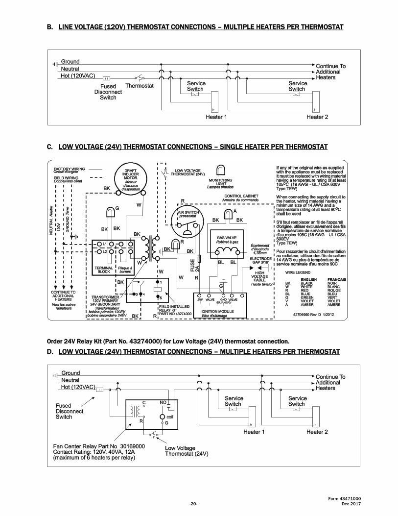
B. LINE VOLTAGE (120V) THERMOSTAT CONNECTIONS – MULTIPLE HEATERS PER THERMOSTAT
C. LOW VOLTAGE (24V) THERMOSTAT CONNECTIONS – SINGLE HEATER PER THERMOSTAT
Order 24V Relay Kit (Part No. 43274000) for Low Voltage (24V) thermostat connection.
D. LOW VOLTAGE (24V) THERMOSTAT CONNECTIONS – MULTIPLE HEATERS PER THERMOSTAT
Form 43471000
Dec 2017 -21-
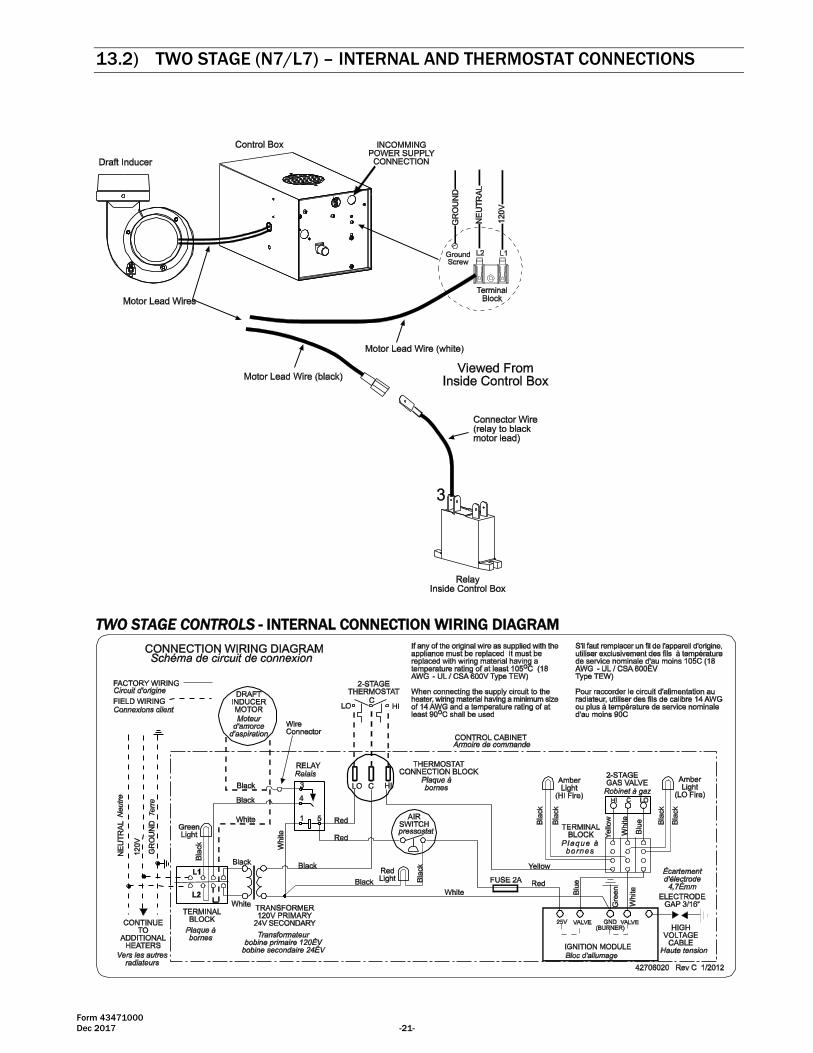
13.2) TWO STAGE (N7/L7) – INTERNAL AND THERMOSTAT CONNECTIONS
TWO STAGE CONTROLS - INTERNAL CONNECTION WIRING DIAGRAM

Form 43471000
-22- Dec 2017
TWO STAGE CONTROLS - SCHEMATIC WIRING DIAGRAM
TWO STAGE CONTROLS - THERMOSTAT WIRING DIAGRAMS
A. LOW VOLTAGE (24V) THERMOSTAT CONNECTIONS – SINGLE HEATER PER THERMOSTAT
Form 43471000
Dec 2017 -23-
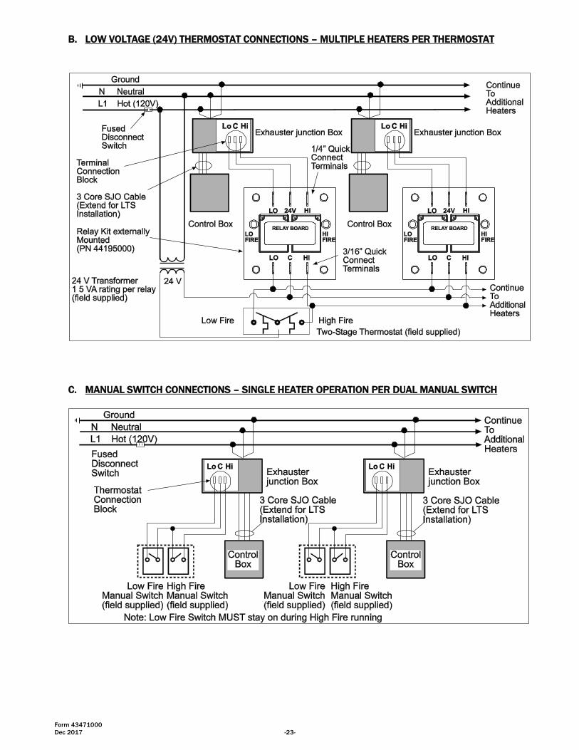
B. LOW VOLTAGE (24V) THERMOSTAT CONNECTIONS – MULTIPLE HEATERS PER THERMOSTAT
C. MANUAL SWITCH CONNECTIONS – SINGLE HEATER OPERATION PER DUAL MANUAL SWITCH
Form 43471000
-24- Dec 2017
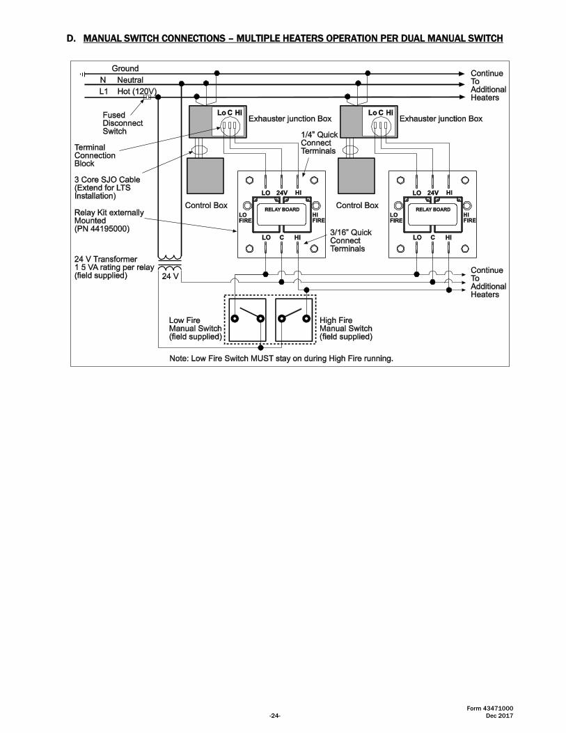
D. MANUAL SWITCH CONNECTIONS – MULTIPLE HEATERS OPERATION PER DUAL MANUAL SWITCH
Form 43471000
Dec 2017 -25-
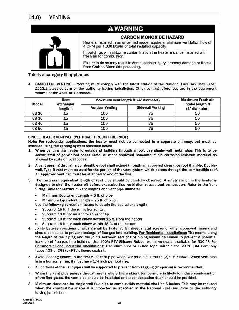
14.0) VENTING
This is a category lll appliance.
A. BASIC FLUE VENTING — Venting must comply with the latest edition of the National Fuel Gas Code (ANSI
Z223.1-latest edition) or the authority having jurisdiction. Other venting references are in the equipment
volume of the ASHRAE Handbook.
SINGLE HEATER VENTING (VERTICAL THROUGH THE ROOF)
Note: For residential applications, the heater must not be connected to a separate chimney, but must be
installed using the venting system specified below.
1. When venting the heater to outside of building through a roof, use single-wall metal pipe. This is to be
constructed of galvanized sheet metal or other approved noncombustible corrosion-resistant material as
allowed by state or local codes.
2. A vent passing through a combustible roof shall extend through an approved clearance roof thimble. Double-
wall, Type B vent must be used for the portion of the vent system which passes through the combustible roof.
An approved vent cap must be attached to end of the flue.
3. The maximum equivalent length of vent pipe should be carefully observed. A safety switch in the heater is
designed to shut the heater off before excessive flue restriction causes bad combustion. Refer to the Vent
Sizing Table for maximum vent lengths and vent pipe diameter.
Minimum Equivalent Length = 5 ft. of pipe
Maximum Equivalent Length = 75 ft. of pipe
Use the following correction factors to obtain the equivalent length:
Subtract 15 ft. if the run is horizontal.
Subtract 10 ft. for an approved vent cap.
Subtract 10 ft. for each elbow beyond 15 ft. from the heater.
Subtract 15 ft. for each elbow within 15 ft. of the heater.
4. Joints between sections of piping shall be fastened by sheet metal screws or other approved means and
should be sealed to prevent leakage of flue gas into building. For Residential Installations: The seams along
the length of the piping and the joints between sections of piping should be sealed to prevent a potential
leakage of flue gas into building. Use 100% RTV Silicone Rubber Adhesive sealant suitable for 500 ºF. For
Commercial and Industrial Installations: Use aluminum or Teflon tape suitable for 550ºF (3M Company
tapes 433 or 363) or RTV silicone sealant.
5. Avoid locating elbows in the first 5’ of vent pipe whenever possible. Limit to (2) 90 elbows. When vent pipe
is in a horizontal run, it must have 1/4 inch per foot rise.
6. All portions of the vent pipe shall be supported to prevent from sagging (6’ spacing is recommended).
7. When the vent pipe passes through areas where the ambient temperature is likely to induce condensation
of the flue gases, the vent pipe should be insulated and a condensation drain should be provided.
8. Minimum clearance for single-wall flue pipe to combustible material shall be 6 inches. This may be reduced
when the combustible material is protected as specified in the National Fuel Gas Code or the authority
having jurisdiction.
Model
Heat
exchanger
length ft
Maximum vent length ft. (4” diameter) Maximum Fresh air
intake length ft
(4” diameter) Vertical Venting Sidewall Venting
CB 20 15 100 75 50
CB 30 15 100 75 50
CB 40 15 100 75 50
CB 50 15 100 75 50
Form 43471000
-26- Dec 2017
9. Single-wall metal pipe shall not originate in any unoccupied attic or concealed space and shall not pass
through any attic, inside wall or concealed space, or through any floor. For the installation of a single-wall
metal pipe through an exterior combustible wall, refer to latest edition of the National Fuel Gas Code or the
authority having jurisdiction.
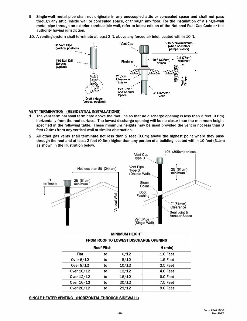
10. A venting system shall terminate at least 3 ft. above any forced air inlet located within 10 ft.
VENT TERMINATION (RESIDENTIAL INSTALLATIONS)
1. The vent terminal shall terminate above the roof line so that no discharge opening is less than 2 feet (0.6m)
horizontally from the roof surface. The lowest discharge opening will be no closer than the minimum height
specified in the following table. These minimum heights may be used provided the vent is not less than 8
feet (2.4m) from any vertical wall or similar obstruction.
2. All other gas vents shall terminate not less than 2 feet (0.6m) above the highest point where they pass
through the roof and at least 2 feet (0.6m) higher than any portion of a building located within 10 feet (3.1m)
as shown in the illustration below.
MINIMUM HEIGHT
FROM ROOF TO LOWEST DISCHARGE OPENING
Roof Pitch H (min)
Flat to 6/12 1.0 Feet
Over 6/12 to 8/12 1.5 Feet
Over 8/12 to 10/12 2.5 Feet
Over 10/12 to 12/12 4.0 Feet
Over 12/12 to 16/12 6.0 Feet
Over 16/12 to 20/12 7.5 Feet
Over 20/12 to 21/12 8.0 Feet
SINGLE HEATER VENTING (HORIZONTAL THROUGH SIDEWALL)
Form 43471000
Dec 2017 -27-
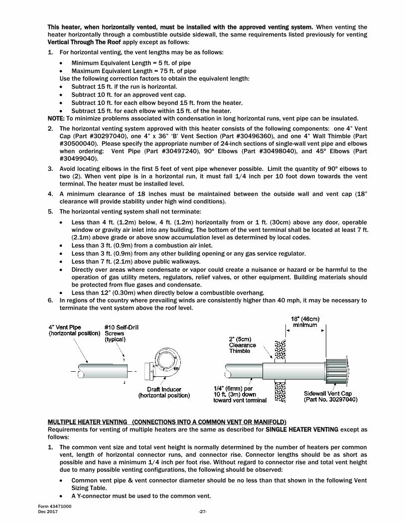
This heater, when horizontally vented, must be installed with the approved venting system. When venting the
heater horizontally through a combustible outside sidewall, the same requirements listed previously for venting
Vertical Through The Roof apply except as follows:
1. For horizontal venting, the vent lengths may be as follows:
Minimum Equivalent Length = 5 ft. of pipe
Maximum Equivalent Length = 75 ft. of pipe
Use the following correction factors to obtain the equivalent length:
Subtract 15 ft. if the run is horizontal.
Subtract 10 ft. for an approved vent cap.
Subtract 10 ft. for each elbow beyond 15 ft. from the heater.
Subtract 15 ft. for each elbow within 15 ft. of the heater.
NOTE: To minimize problems associated with condensation in long horizontal runs, vent pipe can be insulated.
2. The horizontal venting system approved with this heater consists of the following components: one 4” Vent
Cap (Part #30297040), one 4” x 36” ‘B’ Vent Section (Part #30496360), and one 4” Wall Thimble (Part
#30500040). Please specify the appropriate number of 24-inch sections of single-wall vent pipe and elbows
when ordering: Vent Pipe (Part #30497240), 90º Elbows (Part #30498040), and 45º Elbows (Part
#30499040).
3. Avoid locating elbows in the first 5 feet of vent pipe whenever possible. Limit the quantity of 90º elbows to
two (2). When vent pipe is in a horizontal run, it must fall 1/4 inch per 10 foot down towards the vent
terminal. The heater must be installed level.
4. A minimum clearance of 18 inches must be maintained between the outside wall and vent cap (18”
clearance will provide stability under high wind conditions).
5. The horizontal venting system shall not terminate:
Less than 4 ft. (1.2m) below, 4 ft. (1.2m) horizontally from or 1 ft. (30cm) above any door, operable
window or gravity air inlet into any building. The bottom of the vent terminal shall be located at least 7 ft.
(2.1m) above grade or above snow accumulation level as determined by local codes.
Less than 3 ft. (0.9m) from a combustion air inlet.
Less than 3 ft. (0.9m) from any other building opening or any gas service regulator.
Less than 7 ft. (2.1m) above public walkways.
Directly over areas where condensate or vapor could create a nuisance or hazard or be harmful to the
operation of gas utility meters, regulators, relief valves, or other equipment. Building materials should
be protected from flue gases and condensate.
Less than 12” (0.30m) when directly below a combustible overhang.
6. In regions of the country where prevailing winds are consistently higher than 40 mph, it may be necessary to
terminate the vent system above the roof level.
MULTIPLE HEATER VENTING (CONNECTIONS INTO A COMMON VENT OR MANIFOLD)
Requirements for venting of multiple heaters are the same as described for SINGLE HEATER VENTING except as
follows:
1. The common vent size and total vent height is normally determined by the number of heaters per common
vent, length of horizontal connector runs, and connector rise. Connector lengths should be as short as
possible and have a minimum 1/4 inch per foot rise. Without regard to connector rise and total vent height
due to many possible venting configurations, the following should be observed:
Common vent pipe & vent connector diameter should be no less than that shown in the following Vent
Sizing Table.
A Y-connector must be used to the common vent.
Form 43471000
-28- Dec 2017
2. Material for connectors and Y-connectors should be constructed of galvanized sheet metal or other approved
noncombustible corrosion resistant material as allowed by state or local codes. All common vent pipe
should be insulated flue pipe or double-wall, Type B vent.
3. Avoid unnecessary bends. Limit to two (2) 90º elbows.
4. The entire length of vent connector shall be readily accessible for inspection, cleaning and replacement.
5. Groups of heaters with a common vent must be controlled by a common thermostat.
If any heater connected to a common vent system for multiple
heaters is found inoperative, the heater should be disconnected from
the vent system and its entrance into the vent system capped.
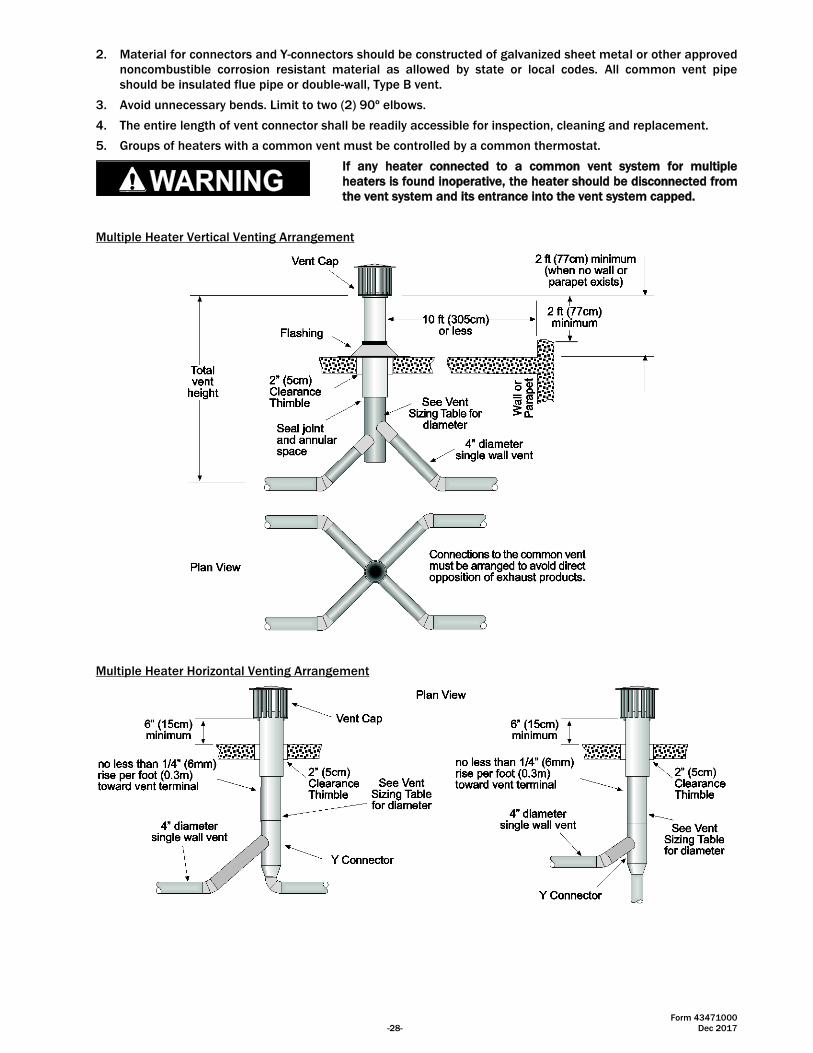
Multiple Heater Vertical Venting Arrangement
Multiple Heater Horizontal Venting Arrangement
Form 43471000
Dec 2017 -29-
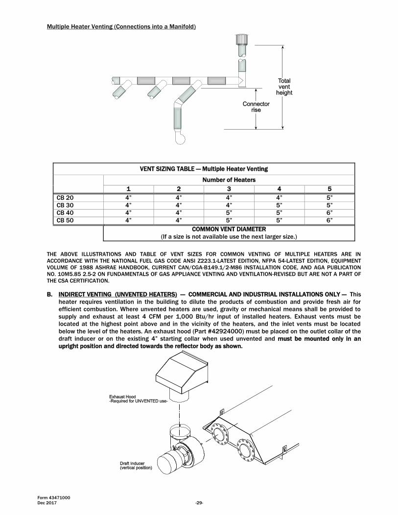
Multiple Heater Venting (Connections into a Manifold)
VENT SIZING TABLE — Multiple Heater Venting
Number of Heaters
1 2 3 4 5
CB 20 4” 4” 4” 4” 5”
CB 30 4” 4” 4” 5” 5”
CB 40 4” 4” 5” 5” 6”
CB 50 4” 4” 5” 5” 6”
COMMON VENT DIAMETER
(If a size is not available use the next larger size.)
THE ABOVE ILLUSTRATIONS AND TABLE OF VENT SIZES FOR COMMON VENTING OF MULTIPLE HEATERS ARE IN
ACCORDANCE WITH THE NATIONAL FUEL GAS CODE ANSI Z223.1-LATEST EDITION, NFPA 54-LATEST EDITION, EQUIPMENT
VOLUME OF 1988 ASHRAE HANDBOOK, CURRENT CAN/CGA-B149.1/2-M86 INSTALLATION CODE, AND AGA PUBLICATION
NO. 10M5.85 2.5-2 ON FUNDAMENTALS OF GAS APPLIANCE VENTING AND VENTILATION-REVISED BUT ARE NOT A PART OF
THE CSA CERTIFICATION.
B. INDIRECT VENTING (UNVENTED HEATERS) — COMMERCIAL AND INDUSTRIAL INSTALLATIONS ONLY — This
heater requires ventilation in the building to dilute the products of combustion and provide fresh air for
efficient combustion. Where unvented heaters are used, gravity or mechanical means shall be provided to
supply and exhaust at least 4 CFM per 1,000 Btu/hr input of installed heaters. Exhaust vents must be
located at the highest point above and in the vicinity of the heaters, and the inlet vents must be located
below the level of the heaters. An exhaust hood (Part #42924000) must be placed on the outlet collar of the
draft inducer or on the existing 4” starting collar when used unvented and must be mounted only in an
upright position and directed towards the reflector body as shown.
Form 43471000
-30- Dec 2017
15.0) AIR FOR COMBUSTION
If indoor combustion air is to be supplied for a tightly enclosed area, one square inch of free area opening shall
be provided below the heater for each 1,000 Btu/hr per hour of heater input. When outside air is used, the
opening below the heater shall be one square inch of free area for each 4,000 Btu/hr of heater input. In
contaminated atmospheres or high humidity areas, optional outside air for combustion is recommended.
Adequate clearances around the perforated fresh air plate must be maintained at all times. In larger open areas
of buildings, infiltration normally is adequate to provide air for combustion.
15.1) DIRECT OUTSIDE AIR FOR COMBUSTION
Outside combustion air should be supplied directly to the heater when the building is subject to negative
pressure, or when contaminants or high humidity are present in the building air. These contaminants include
paints, solvents, corrosive vapors or any other foreign particles that may cause damage to the heater or result in
poor combustion.
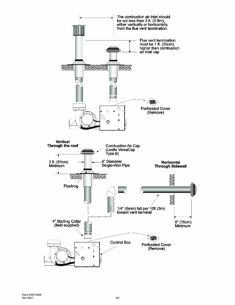
Outside combustion air can be brought directly to the heater by a 4” diameter duct less than 50 ft. long or
equivalent (see table in Section 14.0) based on selected model and heat exchanger lengths). This is attached to
the 4” diameter starting collar. The starting collar is fitted to the top of the control box cabinet after first
removing and discarding the perforated cover. An approved vent cap must be placed directly on the end of the
outside combustion air inlet pipe. The combustion air inlet should be not less than 3 ft. (0.9m), either vertically
or horizontally, from the flue vent termination. The air intake terminal must be located not less than 1 ft. (30cm)
above grade. It is good installation practice to supply combustion air from the same pressure zone as the vent
outlet. Avoid bringing combustion air to the heater from an attic space. There is no guarantee that adequate
combustion air will be supplied.
In colder climates, where necessary, insulate the outside combustion air duct. Avoid locating the outside
combustion air duct directly above the control box. Provide a capped cleanout T as necessary. In high humidity
applications, the control box should be sealed with silicone sealer.
In multiple heater applications, the combustion air intake may be ducted individually or common ducted in the
same configuration as shown for venting in Section 14.0). For combustion air intake duct sizing, please refer to
the Vent Sizing Table and use the diameter indicated, based on the number of heaters per duct.
All vent terminations and Combustion Air Intake Terminations must
be at least 6” higher than anticipated snow depth.
Form 43471000
Dec 2017 -31-
Form 43471000
-32- Dec 2017
16.0) LIGHTING AND SHUTDOWN INSTRUCTIONS
1. Turn on the gas and electrical supply. Rotate the gas valve knob counter-clockwise to the “ON” position.
2. Set the thermostat to call for heat. The blower motor will energize.
3. Ignition should occur after the 30-second air pre-purge.
4. If ignition fails, the unit will spark for approximately 21 seconds and go into safety lockout. Turn the
thermostat (power) off for 60 seconds to take the system out of lockout.
5. If the heater does not light, manually reset the thermostat or shut off power completely for 5 minutes before
attempting to relight.
6. To permanently shut down the heater, rotate the gas valve knob clockwise to the “OFF” position and turn
off the gas and electrical supply.
NOTE: The lighting and shutdown instructions are also shown on the permanent nameplate label attached to the
heater control box.
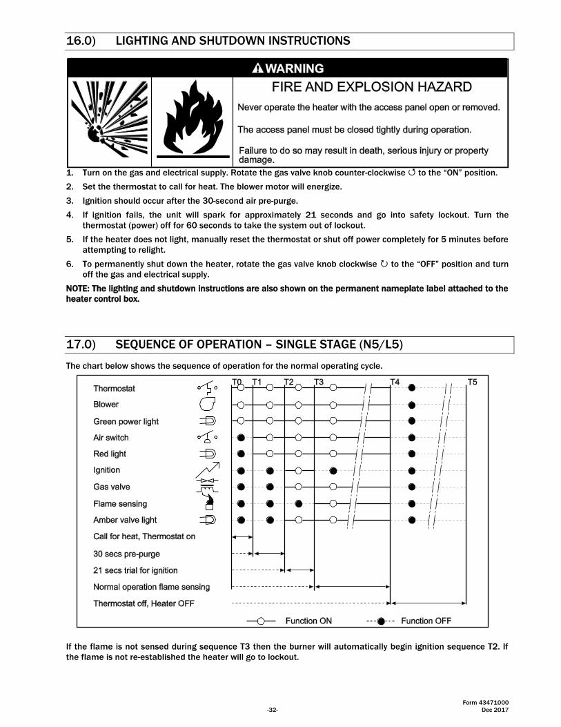
17.0) SEQUENCE OF OPERATION – SINGLE STAGE (N5/L5)
The chart below shows the sequence of operation for the normal operating cycle.
If the flame is not sensed during sequence T3 then the burner will automatically begin ignition sequence T2. If
the flame is not re-established the heater will go to lockout.
Form 43471000
Dec 2017 -33-
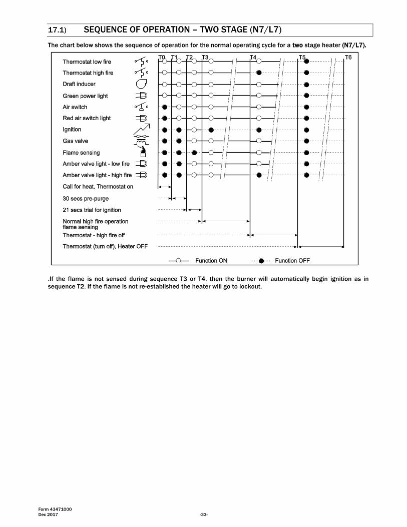
17.1) SEQUENCE OF OPERATION – TWO STAGE (N7/L7)
The chart below shows the sequence of operation for the normal operating cycle for a two stage heater (N7/L7).
.If the flame is not sensed during sequence T3 or T4, then the burner will automatically begin ignition as in
sequence T2. If the flame is not re-established the heater will go to lockout.
Form 43471000
-34- Dec 2017
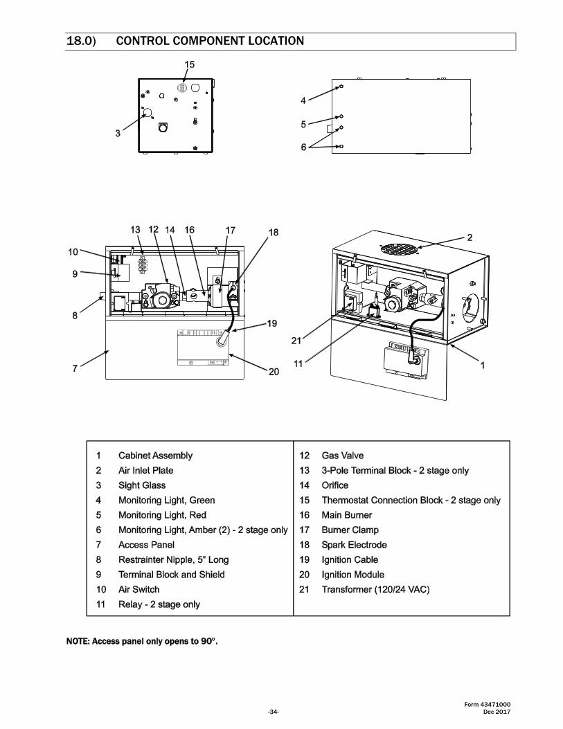
18.0) CONTROL COMPONENT LOCATION
NOTE: Access panel only opens to 90.
Form 43471000
Dec 2017 -35-
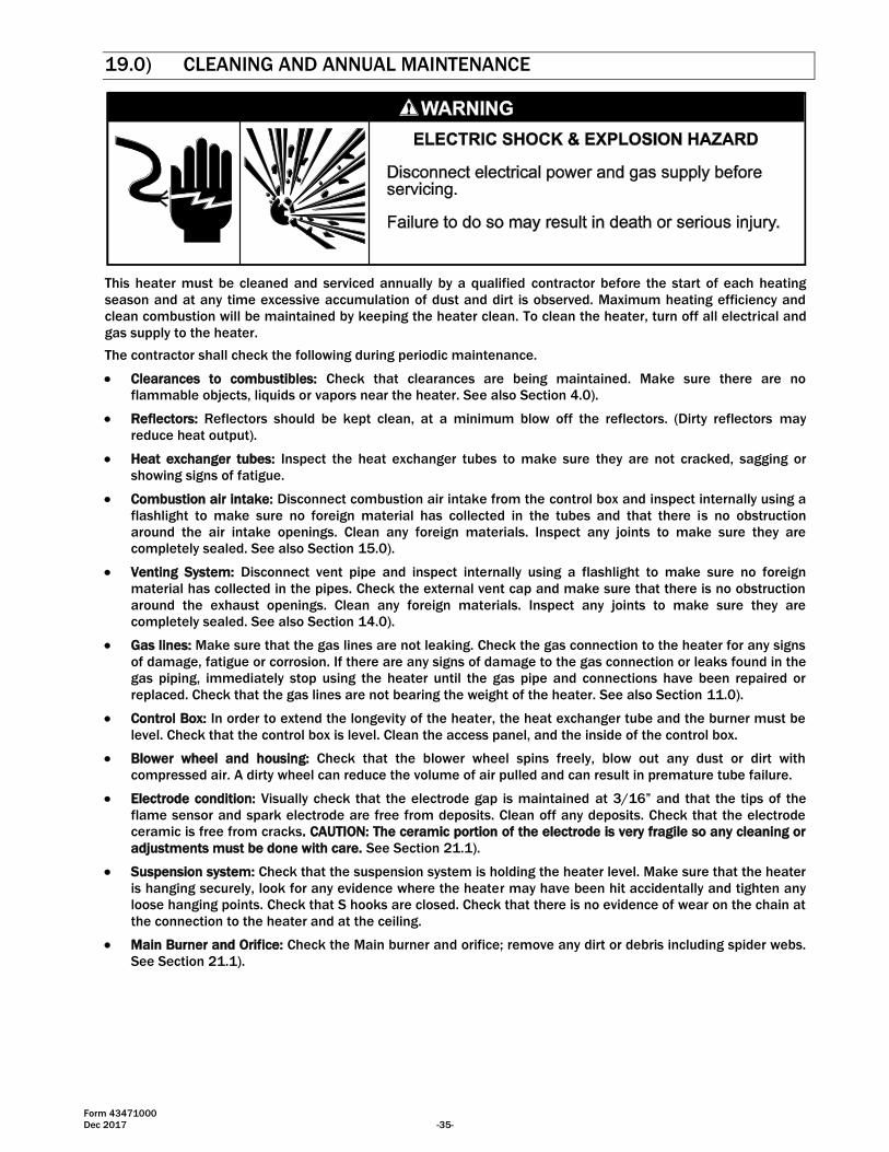
19.0) CLEANING AND ANNUAL MAINTENANCE
This heater must be cleaned and serviced annually by a qualified contractor before the start of each heating
season and at any time excessive accumulation of dust and dirt is observed. Maximum heating efficiency and
clean combustion will be maintained by keeping the heater clean. To clean the heater, turn off all electrical and
gas supply to the heater.
The contractor shall check the following during periodic maintenance.
Clearances to combustibles: Check that clearances are being maintained. Make sure there are no
flammable objects, liquids or vapors near the heater. See also Section 4.0).
Reflectors: Reflectors should be kept clean, at a minimum blow off the reflectors. (Dirty reflectors may
reduce heat output).
Heat exchanger tubes: Inspect the heat exchanger tubes to make sure they are not cracked, sagging or
showing signs of fatigue.
Combustion air intake: Disconnect combustion air intake from the control box and inspect internally using a
flashlight to make sure no foreign material has collected in the tubes and that there is no obstruction
around the air intake openings. Clean any foreign materials. Inspect any joints to make sure they are
completely sealed. See also Section 15.0).
Venting System: Disconnect vent pipe and inspect internally using a flashlight to make sure no foreign
material has collected in the pipes. Check the external vent cap and make sure that there is no obstruction
around the exhaust openings. Clean any foreign materials. Inspect any joints to make sure they are
completely sealed. See also Section 14.0).
Gas lines: Make sure that the gas lines are not leaking. Check the gas connection to the heater for any signs
of damage, fatigue or corrosion. If there are any signs of damage to the gas connection or leaks found in the
gas piping, immediately stop using the heater until the gas pipe and connections have been repaired or
replaced. Check that the gas lines are not bearing the weight of the heater. See also Section 11.0).
Control Box: In order to extend the longevity of the heater, the heat exchanger tube and the burner must be
level. Check that the control box is level. Clean the access panel, and the inside of the control box.
Blower wheel and housing: Check that the blower wheel spins freely, blow out any dust or dirt with
compressed air. A dirty wheel can reduce the volume of air pulled and can result in premature tube failure.
Electrode condition: Visually check that the electrode gap is maintained at 3/16” and that the tips of the
flame sensor and spark electrode are free from deposits. Clean off any deposits. Check that the electrode
ceramic is free from cracks. CAUTION: The ceramic portion of the electrode is very fragile so any cleaning or
adjustments must be done with care. See Section 21.1).
Suspension system: Check that the suspension system is holding the heater level. Make sure that the heater
is hanging securely, look for any evidence where the heater may have been hit accidentally and tighten any
loose hanging points. Check that S hooks are closed. Check that there is no evidence of wear on the chain at
the connection to the heater and at the ceiling.
Main Burner and Orifice: Check the Main burner and orifice; remove any dirt or debris including spider webs.
See Section 21.1).
Form 43471000
-36- Dec 2017
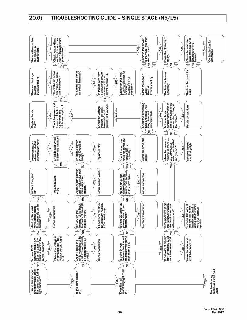
20.0) TROUBLESHOOTING GUIDE – SINGLE STAGE (N5/L5)
Form 43471000
Dec 2017 -37-
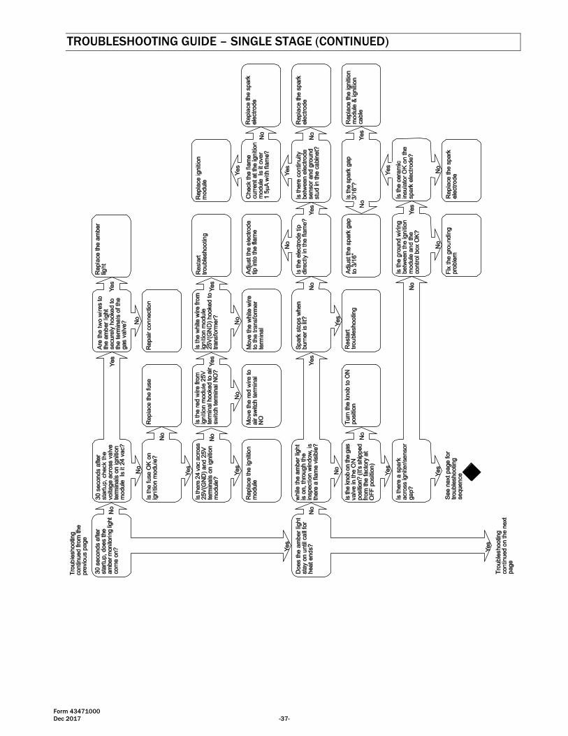
TROUBLESHOOTING GUIDE – SINGLE STAGE (CONTINUED)
Form 43471000
-38- Dec 2017
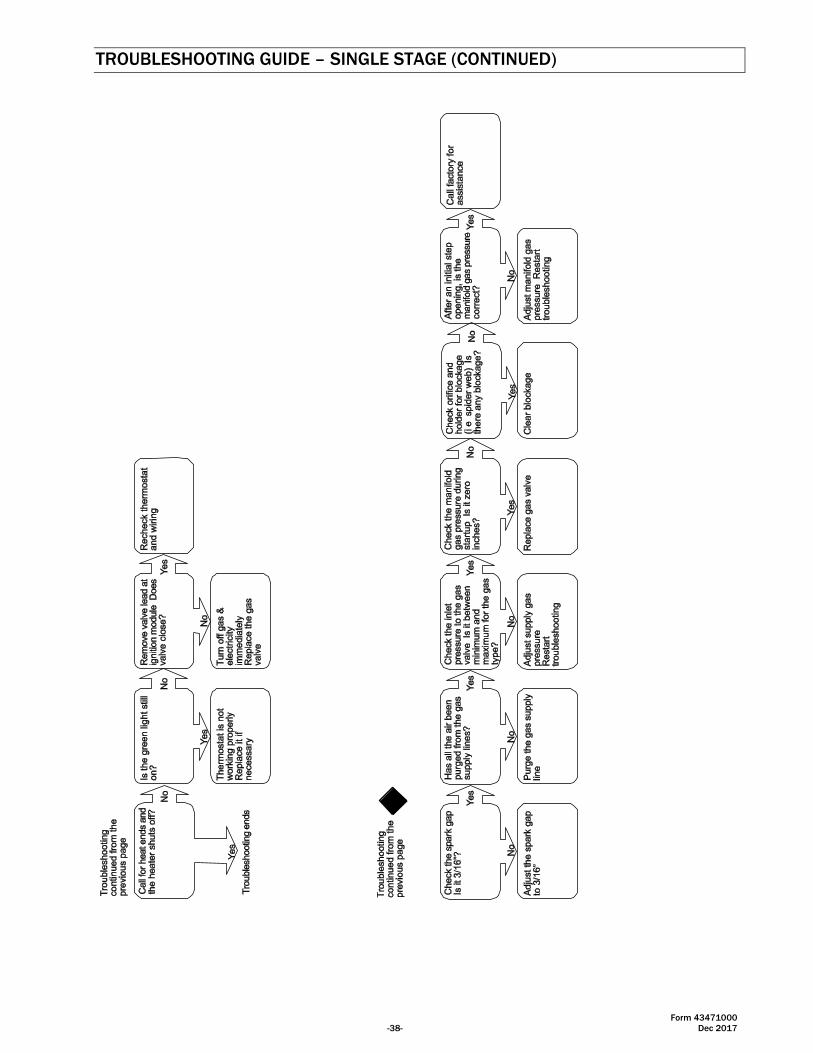
TROUBLESHOOTING GUIDE – SINGLE STAGE (CONTINUED)
Form 43471000
Dec 2017 -39-
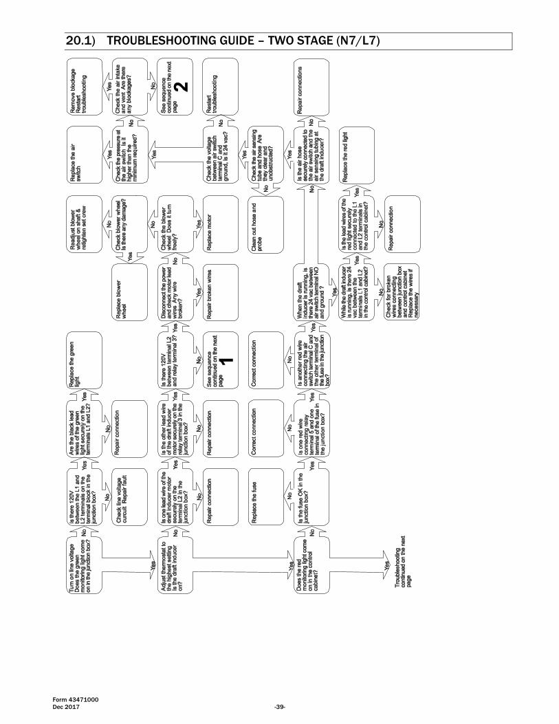
20.1) TROUBLESHOOTING GUIDE – TWO STAGE (N7/L7)
Form 43471000
-40- Dec 2017
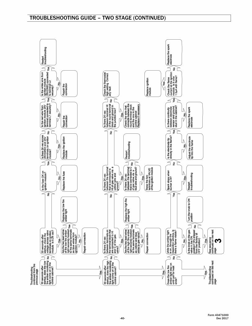
TROUBLESHOOTING GUIDE – TWO STAGE (CONTINUED)
Form 43471000
Dec 2017 -41-
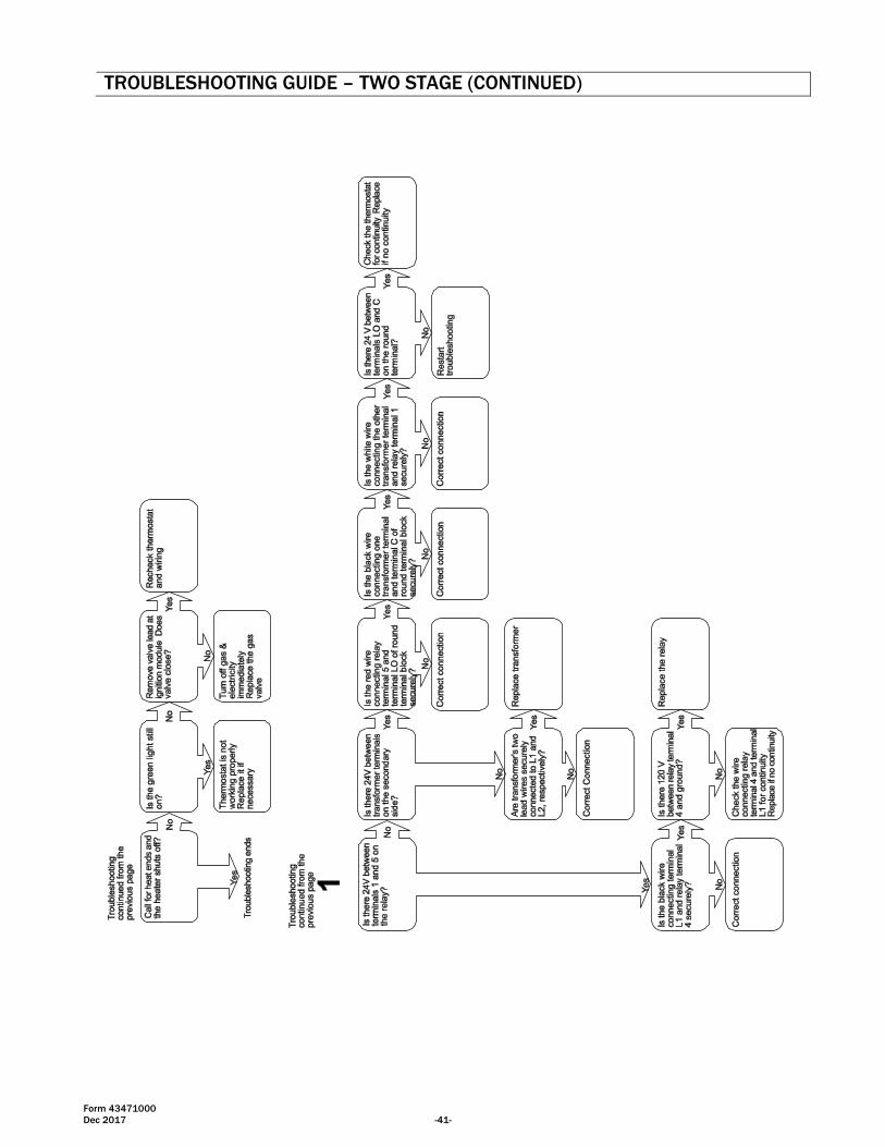
TROUBLESHOOTING GUIDE – TWO STAGE (CONTINUED)
Form 43471000
-42- Dec 2017
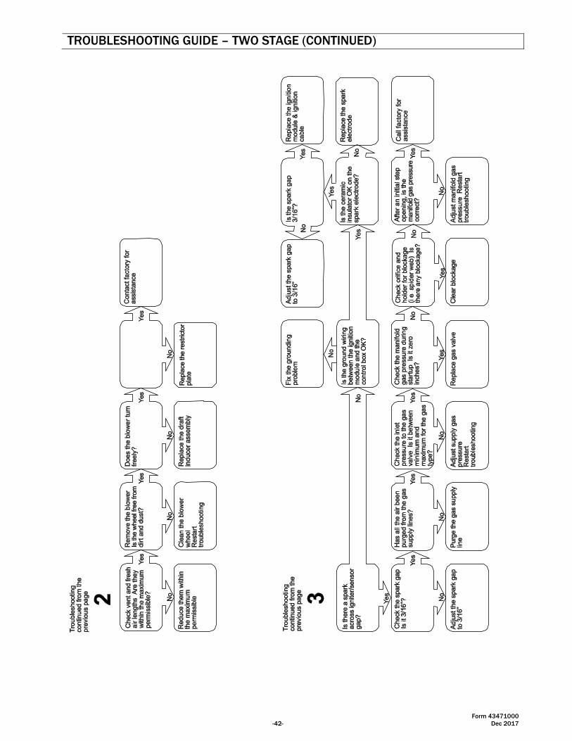
TROUBLESHOOTING GUIDE – TWO STAGE (CONTINUED)
Form 43471000
Dec 2017 -43-
21.0) REPLACING PARTS
Only use genuine Space-Ray replacement parts. Parts are available from the factory for replacement by a
licensed person. Refer to the Replacement Parts Guide in Section 23.0) for all replacement parts.
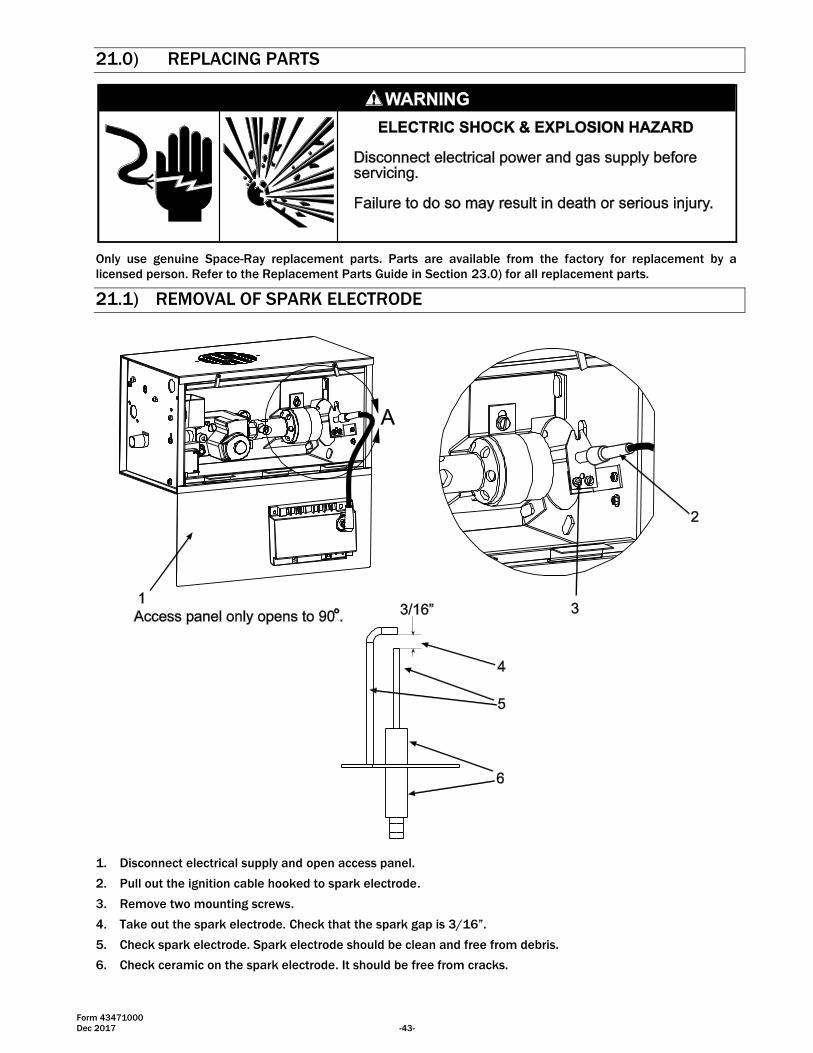
21.1) REMOVAL OF SPARK ELECTRODE
1. Disconnect electrical supply and open access panel.
2. Pull out the ignition cable hooked to spark electrode.
3. Remove two mounting screws.
4. Take out the spark electrode. Check that the spark gap is 3/16”.
5. Check spark electrode. Spark electrode should be clean and free from debris.
6. Check ceramic on the spark electrode. It should be free from cracks.
Form 43471000
-44- Dec 2017
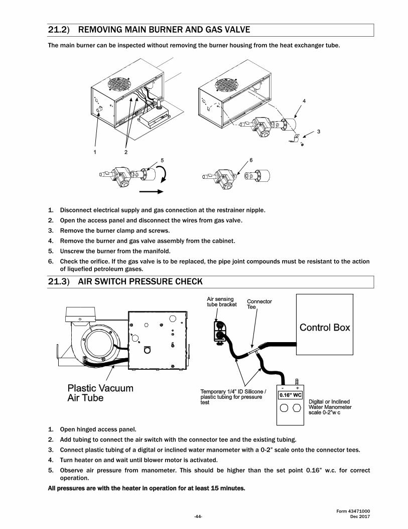
21.2) REMOVING MAIN BURNER AND GAS VALVE
The main burner can be inspected without removing the burner housing from the heat exchanger tube.
1. Disconnect electrical supply and gas connection at the restrainer nipple.
2. Open the access panel and disconnect the wires from gas valve.
3. Remove the burner clamp and screws.
4. Remove the burner and gas valve assembly from the cabinet.
5. Unscrew the burner from the manifold.
6. Check the orifice. If the gas valve is to be replaced, the pipe joint compounds must be resistant to the action
of liquefied petroleum gases.
21.3) AIR SWITCH PRESSURE CHECK
1. Open hinged access panel.
2. Add tubing to connect the air switch with the connector tee and the existing tubing.
3. Connect plastic tubing of a digital or inclined water manometer with a 0-2” scale onto the connector tees.
4. Turn heater on and wait until blower motor is activated.
5. Observe air pressure from manometer. This should be higher than the set point 0.16” w.c. for correct
operation.
All pressures are with the heater in operation for at least 15 minutes.
Form 43471000
Dec 2017 -45-
21.4) IGNITION SYSTEM CHECKS
TO CHECK IGNITION CABLE.
a. Make sure that the ignition cable does not touch any metal surface.
b. Make sure that connections to the stud terminal and the igniter/sensor are clean and tight.
c. Make sure that the ignition cable provides good electrical continuity.
TO CHECK IGNITION SYSTEM GROUNDING.
(Nuisance shutdowns are often caused by a poor or erratic ground.) A common ground is required for the module,
igniter, flame sensor and main burner.
a. Check for good metal-to-metal contact between the igniter bracket and the main burner.
b. Check the ground lead from the GND (BURNER) terminal on the module to the igniter bracket. Make sure
connections are clean and tight. If the wire is damaged or deteriorated, replace it.
c. Replace igniter/sensor with factory replacement part if insulator is cracked.
TO CHECK SPARK IGNITION CIRCUIT.
▲WARNING: The ignition circuit generates a 20,000 Volt open circuit and electrical shock can result.
a. Check ignition cable.
b. Check external fuse located inside the control box.
c. Verify power (24V) at module input terminals and output terminal to gas valve.
d. Replace spark module if fuse and power are OK.
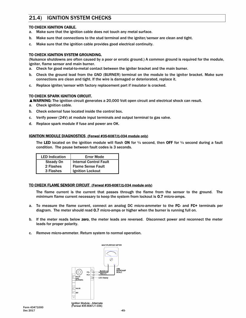
IGNITION MODULE DIAGNOSTICS (Fenwal #35-6087J1-034 module only)
The LED located on the ignition module will flash ON for ¼ second, then OFF for ¼ second during a fault
condition. The pause between fault codes is 3 seconds.
LED Indication Error Mode
Steady On Internal Control Fault
2 Flashes Flame Sense Fault
3 Flashes Ignition Lockout
TO CHECK FLAME SENSOR CIRCUIT (Fenwal #35-6087J1-034 module only)
The flame current is the current that passes through the flame from the sensor to the ground. The
minimum flame current necessary to keep the system from lockout is 0.7 micro-amps.
a. To measure the flame current, connect an analog DC micro-ammeter to the FC- and FC+ terminals per
diagram. The meter should read 0.7 micro-amps or higher when the burner is running full on.
b. If the meter reads below zero, the meter leads are reversed. Disconnect power and reconnect the meter
leads for proper polarity.
c. Remove micro-ammeter. Return system to normal operation.
Form 43471000
-46- Dec 2017
21.5) MOTOR AND BLOWER WHEEL CHECK
If draft inducer motor fails to run:
a. Check power supply to junction box.
b. Check for loose or broken motor lead wire.
c. Check to see that blower wheel turns freely and is not rubbing housing. Blower wheel may have worked
loose from shaft and jammed against housing.
d. Check for blower wheel damage; replace if necessary. If no damage, readjust blower wheel on shaft &
retighten set screw.
e. If all above does not correct, replace motor.
22.0) INSTALLATION DATA
Date of
Installation:
# of Heaters in
System:
Serial
No.
Model: CB
N = Natural Gas
L = Propane Gas
Form 43471000
Dec 2017 -47-
23.0) REPLACEMENT PARTS GUIDE
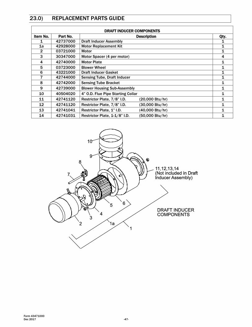
DRAFT INDUCER COMPONENTS
Item No. Part No. Description Qty.
1 42737000 Draft Inducer Assembly 1
1a 42928000 Motor Replacement Kit 1
2 03721000 Motor 1
3 30347000 Motor Spacer (4 per motor) 4
4 42740000 Motor Plate 1
5 03723000 Blower Wheel 1
6 43221000 Draft Inducer Gasket 1
7 42744000 Sensing Tube, Draft Inducer 1
8 42742000 Sensing Tube Bracket 1
9 42739000 Blower Housing Sub-Assembly 1
10 40504020 4” O.D. Flue Pipe Starting Collar 1
11 42741120 Restrictor Plate, 7/8” I.D. (20,000 Btu/hr) 1
12 42741120 Restrictor Plate, 7/8” I.D. (30,000 Btu/hr) 1
13 42741041 Restrictor Plate, 1” I.D. (40,000 Btu/hr) 1
14 42741031 Restrictor Plate, 1-1/8” I.D. (50,000 Btu/hr) 1
Form 43471000
-48- Dec 2017
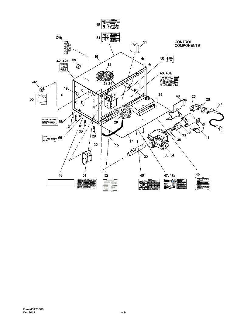
CONTROL COMPONENTS
Item No. Part No. Description Qty.
15 03988150 Plastic Vacuum Air Tube, 15” long 1
16 42750000 Cabinet Assembly 1
17 42751000 Access Panel 1
18 42752000 Air Inlet Plate (Perforated) 1
19 42447000 Sight Glass 1
20 42837040 Air Switch Kit, set @0.11” W.C., #NS2-0307-00 1
21 30383000 Relay, 24V SPST-NO (2-stage controls) 1
22 30279980 Transformer, AT120B1051 1
23 42709000 Terminal Block Shield 1
24 30281000 Terminal Block, EK-204 1
24a 30743000 Terminal Block, EL-3008 (2-stage controls) 1
24b 30738030 Thermostat Connection Block – 3 Pole (2-stage controls) 1
25 42759000 Electrode Bracket 1
26 30295000 Electrode PSE-GF1 (Igniter/Sensor) 1
27 30314070 Ignition Cable, 7” long 1
28 44010010 Kit, Spark Module – Fenwal #35-608711-034 1
29 42398040 Monitoring Light, Green 1
30 42398060 Monitoring Light, Red 1
31 42398050 Monitoring Light, Amber (2 each for 2-stage controls) 1
32 42757000 Restrainer Nipple, 5” long 1
33 44010250 Kit, Gas Valve – WR #36J23-203B1 Single Stage (natural gas) 1
33a 44010260 Kit, Gas Valve – WR #36J23-204B1 Single Stage (propane gas) 1
34 44010310 Kit, Gas Valve – WR #36J58-201B1 Two Stage (natural gas) 1
34a 44010320 Kit, Gas Valve – WR #36J58-202B1 Two Stage (propane gas) 1
35 42701000 Orifice Fitting – ½” NPT x 7/16-27 1
37 03259xxx Orifice for CB20-50 (State Model & Gas Type for Size) 1
38 42700000 Main Burner 1
39 30148000 Universal Bushing, 7/8” 1
40 42755000 Burner Bracket Sub-Assembly 1
41 42753000 Burner Clamp 1
Labels / Manual
Item No. Part No. Description Qty.
42 42785000 Label, Wire Diagram – Ladder (1-stage controls) 1
42a 42785030 Label, Wire Diagram – Ladder (2-stage controls) 1
43 42706000 Label, Wire Diagram – Connections (1-stage controls) 1
43a 42706020 Label, Wire Diagram – Connections (2-stage controls) 1
44 43471000 Installation and Operation Instructions (not shown) 1
45 43344050 Label, Gas Connector Warning 1
46 43470000 Label, Clearance to Combustibles 1
47 42848030 Label, Nameplate (1-stage controls) 1
47a 42848190 Label, Nameplate (2-stage controls)
48 42013000 Label, “Space-Ray” Logo 1
49 43470030 Label, Warning (residential) 1
50 42834000 Label, 120V Caution 1
51 42875000 Label, Warning 1
52 43470040 Label, Operating Instructions 1
53 43470050 Label, Caution/Attention 1
54 43470060 Label, Horizontal Venting 1
55 43269060 Label, 24V Thermostat Connection – (2-stage controls) 1
56 43269070 Label, Low/High Fire (2-stage controls) 1
Form 43471000
Dec 2017 -49-
Form 43471000
-50- Dec 2017
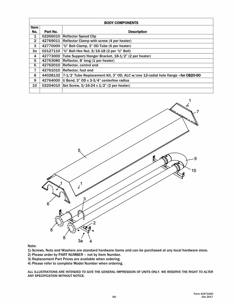
BODY COMPONENTS
Item
No. Part No. Description
1 02266010 Reflector Speed Clip
2 42769011 Reflector Clamp with screw (4 per heater)
3 42770000 “U” Bolt Clamp, 3” OD Tube (6 per heater)
3a 02127110 “U” Bolt Hex Nut, 5/16-18 (2 per “U” Bolt)
4 42773000 Tube Support/Hanger Bracket, 18-1/2” (2 per heater)
5 42763080 Reflector, 8’ long (1 per heater)
6 42762010 Reflector, control end
7 42761010 Reflector, foot end
8 44028132 7-1/2’ Tube Replacement Kit, 3” OD, ALC w/one 12-radial hole flange –for CB20-50
9 42764000 U Bend, 3” OD x 3-3/4” centerline radius
10 02254010 Set Screw, 5/16-24 x 1/2” (2 per heater)
Note:
1) Screws, Nuts and Washers are standard hardware items and can be purchased at any local hardware store.
2) Please order by PART NUMBER – not by Item Number.
3) Replacement Part Prices are available when ordering.
4) Please refer to complete Model Number when ordering.
ALL ILLUSTRATIONS ARE INTENDED TO GIVE THE GENERAL IMPRESSION OF UNITS ONLY. WE RESERVE THE RIGHT TO ALTER
ANY SPECIFICATION WITHOUT NOTICE.
Form 43471000
Dec 2017 -51-
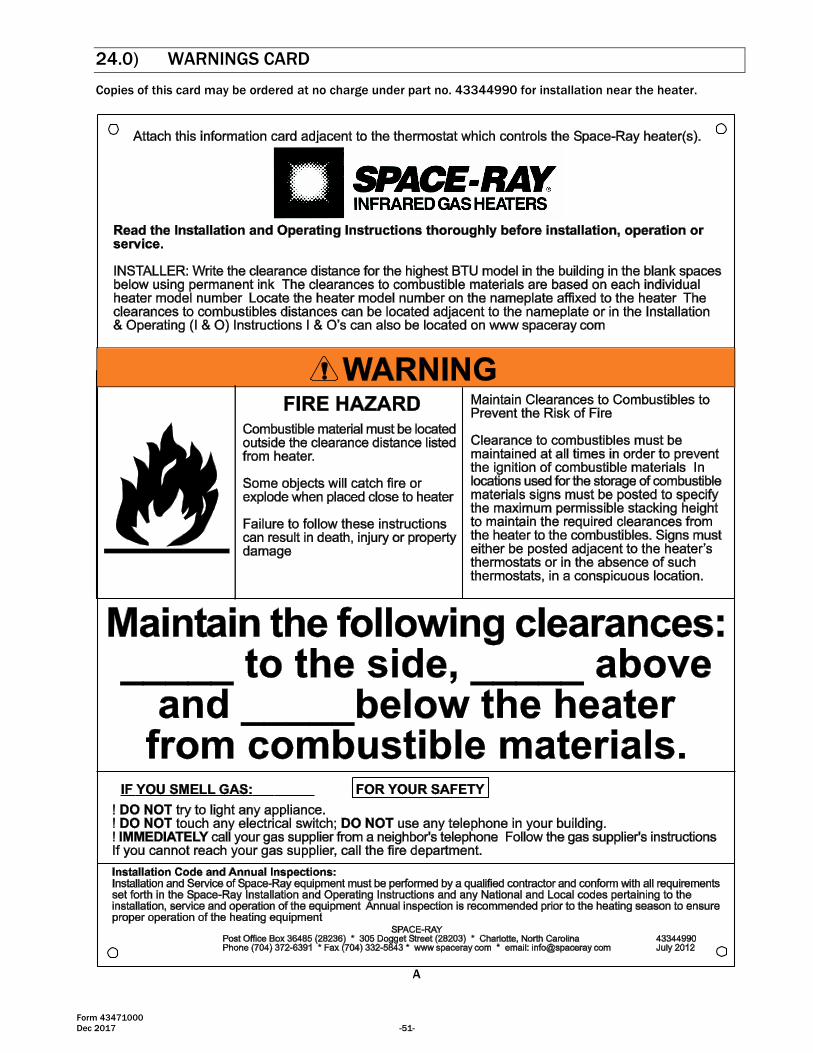
24.0) WARNINGS CARD
Copies of this card may be ordered at no charge under part no. 43344990 for installation near the heater.
A


![Caliper Operation Instructions[1]](https://img.pdfslide.net/doc/110x75/577cc5701a28aba7119c6424/caliper-operation-instructions1.jpg)