Embed Size (px)
Citation preview
WOOD BOILER INSTRUCTIONS Page 1 Copyright © 2011 Seton Wood Boilers all rights reserved
NEVER OPERATE WITH THE FEED DOOR OPEN!! THE SETON BOILER MUST BE INSTALLED IN A ENCLOSED, INSULATED ROOM.
IT SHOULD BE REMOTE FROM THE LIVING SPACE.
Installation and Operation Instructions for W-90E W-130E W-180E
SAFETY INSTRUCTIONS Safety Notice: If this is not properly installed, a house/building fire may result. For your safety, contact local building or fire officials about permits, restrictions, and installation requirements for your area.
NEVER BLOCK DRAFT IN OPEN POSITION
Do not open the feed door until the wood has burned down some. Avoid trying to see how the fire is burning shortly after you fill it. All wood burning appliances will smoke if you open the feed door
when it is full of wood. Do not over-fire the boiler.
Over-firing will occur if the feed door is left open or the draft is blocked open during operation.
Such actions can result in very dangerous operating conditions.
Because of the very high efficiency of the Seton boiler the flue gas exhaust temperatures can be low enough to cause condensation in the chimney. This condensation may, over
time, damage a masonry chimney. If you have condensation in your chimney, a insulated stainless steel chimney liner should be installed inside the flue
SETON WOOD BURNING PRODUCTS 406-295-9902 24 RIVERVIEW DR. TROY MT 59935
Seton Wood Boilers Seton Wood Boilers Seton Wood Boilers There is no substitute for doing it right.There is no substitute for doing it right.There is no substitute for doing it right.There is no substitute for doing it right.
PLUMB BOTH RELIEF VALVES TO A SAFE LOCATION PIPE MUST RUN DOWN HILL ITS FULL LENGTH. PLUMB TO AN OUTSIDE AREA., DO NOT
ALLOW THE PIPE TO EXTEND OUTSIDE FAR ENOUGH TO FREE ZE. O NOT REDUCE THE PIPE SIZE. DO NOT PUT THREADS ON THE OPEN END OF THE DRAIN PIPE
DO NOT JOIN THE TWO DRAINS TOGETHER
WARNING!! ATOMIZED POLYPROPYLENE GLYCOL AT HIGH TEMPERATURES CAN CAUSE AN EXPLOSION!!
WOOD BOILER INSTRUCTIONS Page 2 Copyright © 2011 Seton Wood Boilers all rights reserved
BOILER INSTALLATION IMPORTANT NOTES Seton Wood Burning Products
Certificate of Boiler Efficiency
Eligibility for the American Recovery and Reinvestment Act of 2009
Internal Revenue Service Tax Credit
We are pleased to inform you that as a part of the recent stimulus package, The Seton Wood Burning Products Boilers qualify for a $1,500.00 federal tax credit. It is not necessary to submit this certificate with your tax return, however, please keep this certificate for your records as
required by the IRS. Please consult your tax professional to determine if you are eligible for this credit.
The following “Biomass Burning Stoves” are “qualified energy property” as defined in Section 2.03(c) of the Internal Revenue Service Notice 2009-53:
Boiler Manufacturer: Seton Wood Burning Products Models: Seton Boiler Design, W-90-E, W-130-E and W-180-E
Under penalties of perjury, I declare that I have examined this certification statement, and to the best of my knowledge and belief, the facts are true, correct and complete.
Signed______________________ Fred Seton, OWNER
Seton Wood Burning Products
8775 Hwy 2 N. Troy MT 59935
Office 406-295-9902 www.rohor.com
WOOD BOILER INSTRUCTIONS Page 3 Copyright © 2011 Seton Wood Boilers all rights reserved
BOILER INSTALLATION IMPORTANT NOTES
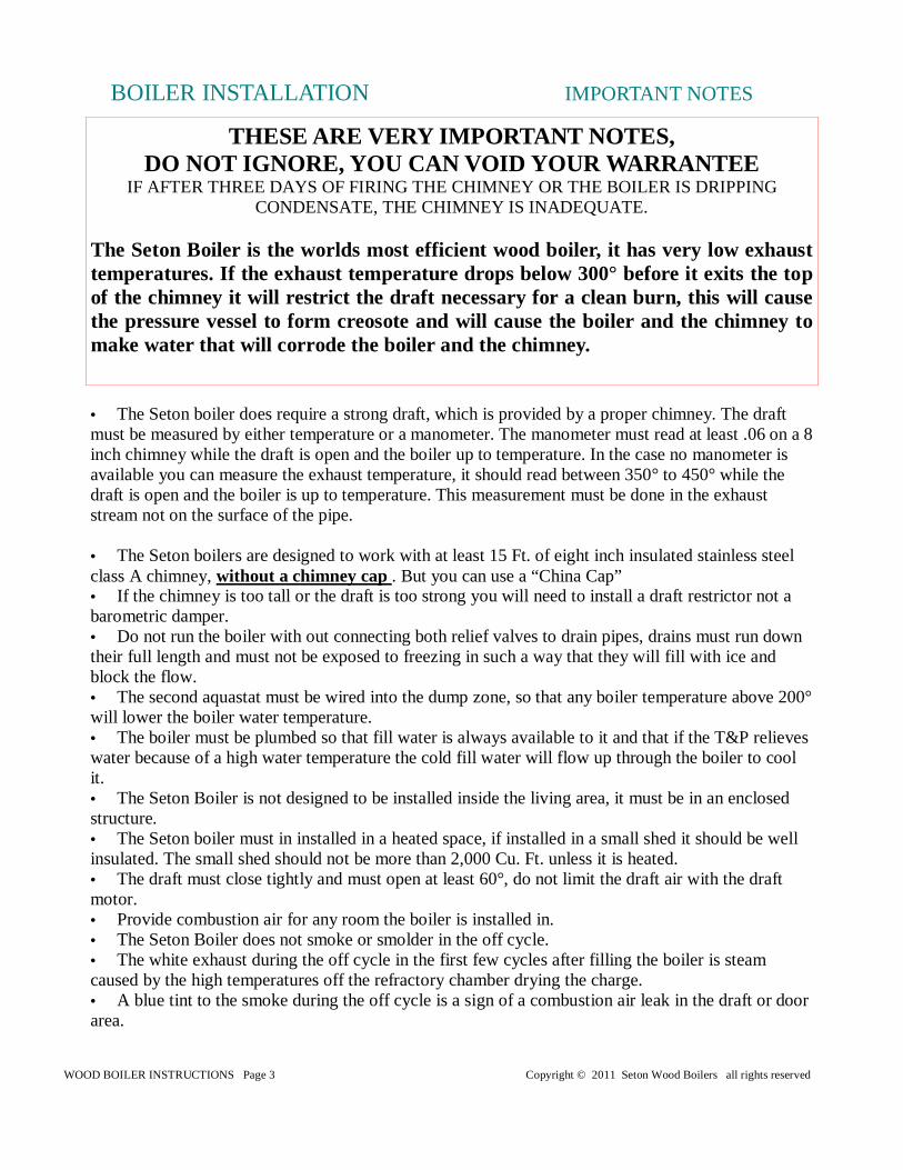
• The Seton boiler does require a strong draft, which is provided by a proper chimney. The draft must be measured by either temperature or a manometer. The manometer must read at least .06 on a 8 inch chimney while the draft is open and the boiler up to temperature. In the case no manometer is available you can measure the exhaust temperature, it should read between 350° to 450° while the draft is open and the boiler is up to temperature. This measurement must be done in the exhaust stream not on the surface of the pipe. • The Seton boilers are designed to work with at least 15 Ft. of eight inch insulated stainless steel class A chimney, without a chimney cap . But you can use a “China Cap” • If the chimney is too tall or the draft is too strong you will need to install a draft restrictor not a barometric damper. • Do not run the boiler with out connecting both relief valves to drain pipes, drains must run down their full length and must not be exposed to freezing in such a way that they will fill with ice and block the flow. • The second aquastat must be wired into the dump zone, so that any boiler temperature above 200° will lower the boiler water temperature. • The boiler must be plumbed so that fill water is always available to it and that if the T&P relieves water because of a high water temperature the cold fill water will flow up through the boiler to cool it. • The Seton Boiler is not designed to be installed inside the living area, it must be in an enclosed structure. • The Seton boiler must in installed in a heated space, if installed in a small shed it should be well insulated. The small shed should not be more than 2,000 Cu. Ft. unless it is heated. • The draft must close tightly and must open at least 60°, do not limit the draft air with the draft motor. • Provide combustion air for any room the boiler is installed in. • The Seton Boiler does not smoke or smolder in the off cycle. • The white exhaust during the off cycle in the first few cycles after filling the boiler is steam caused by the high temperatures off the refractory chamber drying the charge. • A blue tint to the smoke during the off cycle is a sign of a combustion air leak in the draft or door area.
THESE ARE VERY IMPORTANT NOTES, DO NOT IGNORE, YOU CAN VOID YOUR WARRANTEE
IF AFTER THREE DAYS OF FIRING THE CHIMNEY OR THE BOILER IS DRIPPING CONDENSATE, THE CHIMNEY IS INADEQUATE.
The Seton Boiler is the worlds most efficient wood boiler, it has very low exhaust temperatures. If the exhaust temperature drops below 300° before it exits the top of the chimney it will restrict the draft necessary for a clean burn, this will cause the pressure vessel to form creosote and will cause the boiler and the chimney to make water that will corrode the boiler and the chimney.
WOOD BOILER INSTRUCTIONS Page 4 Copyright © 2011 Seton Wood Boilers all rights reserved
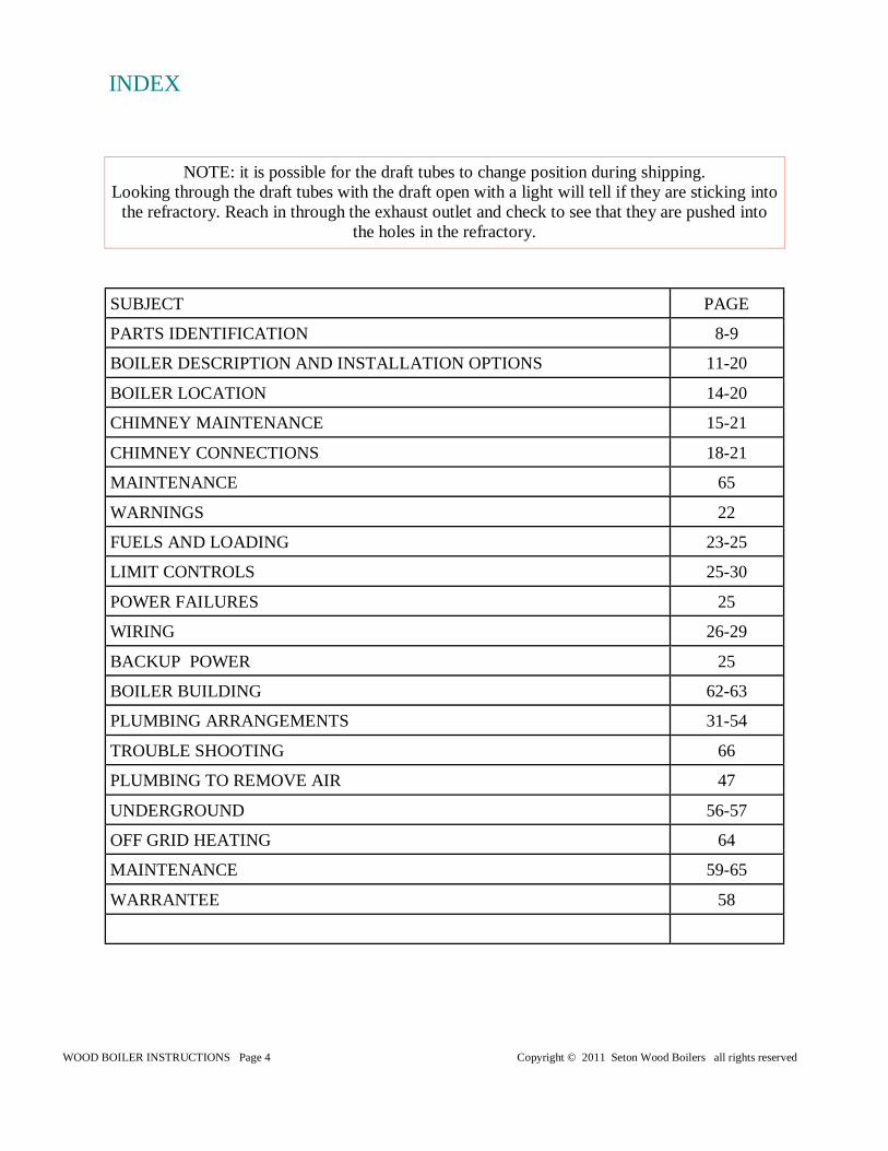
INDEX
SUBJECT PAGE
PARTS IDENTIFICATION 8-9
BOILER DESCRIPTION AND INSTALLATION OPTIONS 11-20
BOILER LOCATION 14-20
CHIMNEY MAINTENANCE 15-21
CHIMNEY CONNECTIONS 18-21
MAINTENANCE 65
WARNINGS 22
FUELS AND LOADING 23-25
LIMIT CONTROLS 25-30
POWER FAILURES 25
WIRING 26-29
BACKUP POWER 25
BOILER BUILDING 62-63
PLUMBING ARRANGEMENTS 31-54
TROUBLE SHOOTING 66
PLUMBING TO REMOVE AIR 47
UNDERGROUND 56-57
OFF GRID HEATING 64
MAINTENANCE 59-65
WARRANTEE 58
NOTE: it is possible for the draft tubes to change position during shipping. Looking through the draft tubes with the draft open with a light will tell if they are sticking into
the refractory. Reach in through the exhaust outlet and check to see that they are pushed into the holes in the refractory.
WOOD BOILER INSTRUCTIONS Page 5 Copyright © 2011 Seton Wood Boilers all rights reserved
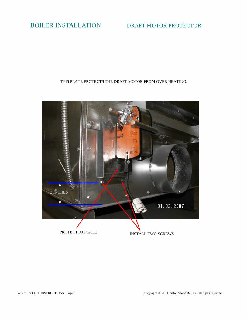
BOILER INSTALLATION DRAFT MOTOR PROTECTOR
PROTECTOR PLATE INSTALL TWO SCREWS
3 INCHES
THIS PLATE PROTECTS THE DRAFT MOTOR FROM OVER HEATING.
WOOD BOILER INSTRUCTIONS Page 6 Copyright © 2011 Seton Wood Boilers all rights reserved
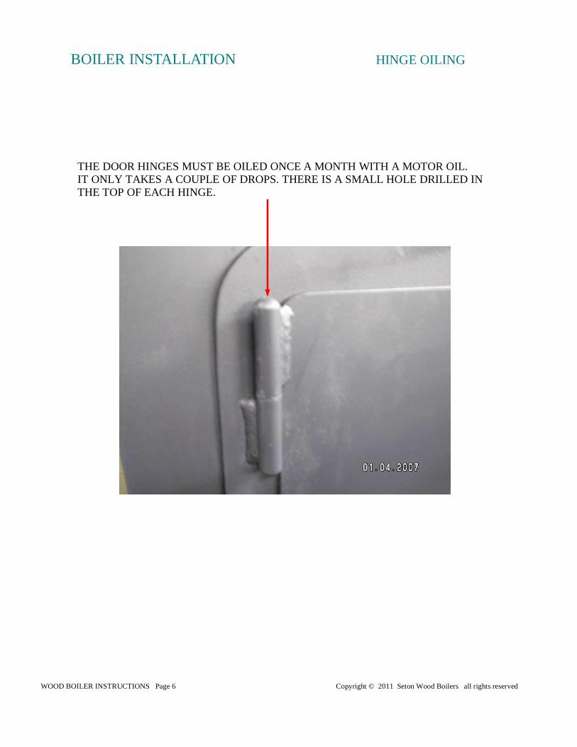
BOILER INSTALLATION HINGE OILING
THE DOOR HINGES MUST BE OILED ONCE A MONTH WITH A MOTOR OIL. IT ONLY TAKES A COUPLE OF DROPS. THERE IS A SMALL HOLE DRILLED IN THE TOP OF EACH HINGE.
WOOD BOILER INSTRUCTIONS Page 7 Copyright © 2011 Seton Wood Boilers all rights reserved
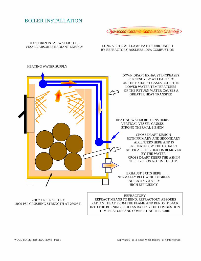
Advanced Ceramic Combustion Chamber
DOWN DRAFT EXHAUST INCREASES EFFICIENCY BY AT LEAST 15%.
AS THE EXHAUST GASES COOL THE LOWER WATER TEMPERATURES
OF THE RETURN WATER CAUSES A GREATER HEAT TRANSFER
TOP HORIZONTAL WATER TUBE VESSEL ABSORBS RADIANT ENERGY
CROSS DRAFT DESIGN BOTH PRIMARY AND SECONDARY
AIR ENTERS HERE AND IS PREHEATED BY THE EXHAUST
AFTER ALL THE HEAT IS REMOVED BY THE WATER
CROSS DRAFT KEEPS THE ASH IN THE FIRE BOX NOT IN THE AIR.
EXHAUST EXITS HERE NORMALLY BELOW 300 DEGREES
INDICATING A VERY HIGH EFFICIENCY
HEATING WATER RETURNS HERE. VERTICAL VESSEL CAUSES STRONG THERMAL SIPHON
HEATING WATER SUPPLY
LONG VERTICAL FLAME PATH SURROUNDED BY REFRACTORY ASSURES 100% COMBUSTION
REFRACTORY REFRACT MEANS TO BEND, REFRACTORY ABSORBS
RADIANT HEAT FROM THE FLAME AND BENDS IT BACK INTO THE BURNING PROCESS RAISING THE COMBUSTION
TEMPERATURE AND COMPLETING THE BURN
2800° + REFRACTORY 3000 PSI. CRUSHING STRENGTH AT 2500° F.
BOILER INSTALLATION
WOOD BOILER INSTRUCTIONS Page 8 Copyright © 2011 Seton Wood Boilers all rights reserved
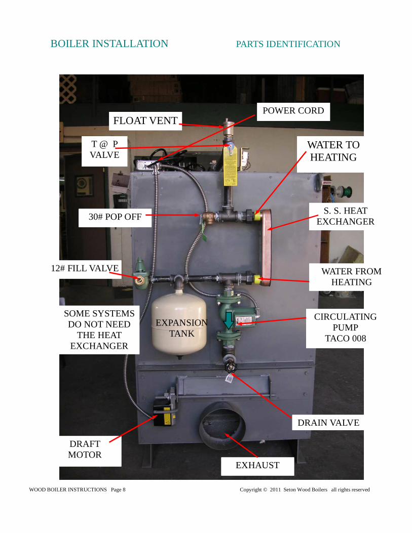
BOILER INSTALLATION PARTS IDENTIFICATION
EXPANSION TANK
DRAFT MOTOR
WATER TO HEATING
WATER FROM HEATING
EXHAUST
CIRCULATING PUMP
TACO 008
FLOAT VENT
30# POP OFF
12# FILL VALVE
POWER CORD
T @ P VALVE
DRAIN VALVE
S. S. HEAT EXCHANGER
SOME SYSTEMS DO NOT NEED
THE HEAT EXCHANGER
WOOD BOILER INSTRUCTIONS Page 9 Copyright © 2011 Seton Wood Boilers all rights reserved
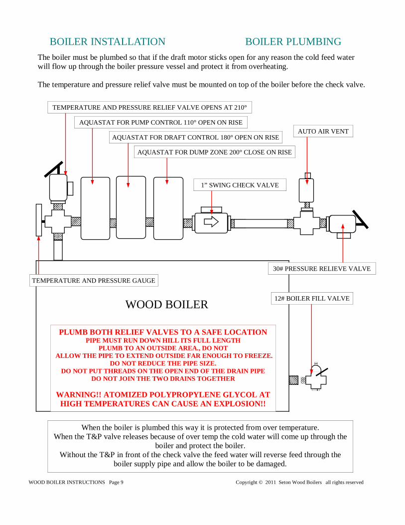
BOILER INSTALLATION BOILER PLUMBING The boiler must be plumbed so that if the draft motor sticks open for any reason the cold feed water will flow up through the boiler pressure vessel and protect it from overheating. The temperature and pressure relief valve must be mounted on top of the boiler before the check valve.
WOOD BOILER
TEMPERATURE AND PRESSURE GAUGE
TEMPERATURE AND PRESSURE RELIEF VALVE OPENS AT 210°
AQUASTAT FOR DRAFT CONTROL 180° OPEN ON RISE
AQUASTAT FOR DUMP ZONE 200° CLOSE ON RISE
1” SWING CHECK VALVE
30# PRESSURE RELIEVE VALVE
AUTO AIR VENT
When the boiler is plumbed this way it is protected from over temperature. When the T&P valve releases because of over temp the cold water will come up through the
boiler and protect the boiler. Without the T&P in front of the check valve the feed water will reverse feed through the
boiler supply pipe and allow the boiler to be damaged.
12# BOILER FILL VALVE
AQUASTAT FOR PUMP CONTROL 110° OPEN ON RISE
PLUMB BOTH RELIEF VALVES TO A SAFE LOCATION PIPE MUST RUN DOWN HILL ITS FULL LENGTH
PLUMB TO AN OUTSIDE AREA., DO NOT ALLOW THE PIPE TO EXTEND OUTSIDE FAR ENOUGH TO FREE ZE.
DO NOT REDUCE THE PIPE SIZE. DO NOT PUT THREADS ON THE OPEN END OF THE DRAIN PIPE
DO NOT JOIN THE TWO DRAINS TOGETHER
WARNING!! ATOMIZED POLYPROPYLENE GLYCOL AT HIGH TEMPERATURES CAN CAUSE AN EXPLOSION!!
WOOD BOILER INSTRUCTIONS Page 10 Copyright © 2011 Seton Wood Boilers all rights reserved
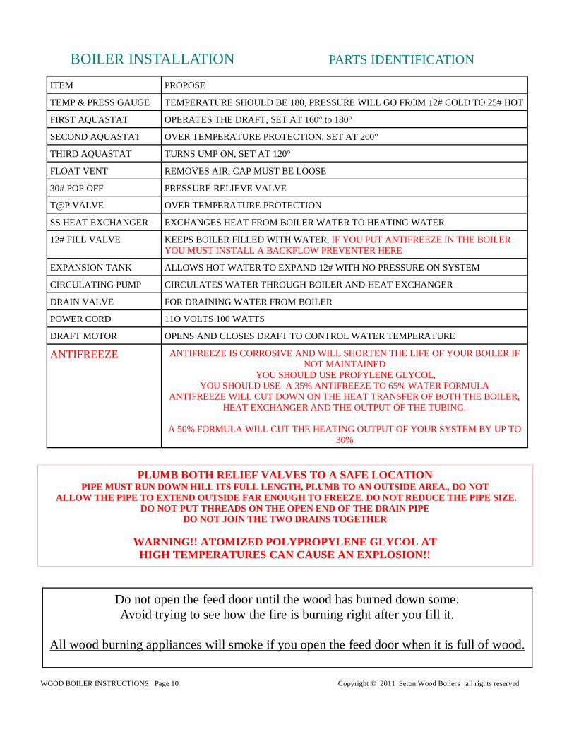
BOILER INSTALLATION PARTS IDENTIFICATION
ITEM PROPOSE
TEMP & PRESS GAUGE TEMPERATURE SHOULD BE 180, PRESSURE WILL GO FROM 12# COLD TO 25# HOT
FIRST AQUASTAT OPERATES THE DRAFT, SET AT 160° to 180°
SECOND AQUASTAT OVER TEMPERATURE PROTECTION, SET AT 200°
THIRD AQUASTAT TURNS UMP ON, SET AT 120°
FLOAT VENT REMOVES AIR, CAP MUST BE LOOSE
30# POP OFF PRESSURE RELIEVE VALVE
T@P VALVE OVER TEMPERATURE PROTECTION
SS HEAT EXCHANGER EXCHANGES HEAT FROM BOILER WATER TO HEATING WATER
12# FILL VALVE KEEPS BOILER FILLED WITH WATER, IF YOU PUT ANTIFREEZE IN THE BOILER YOU MUST INSTALL A BACKFLOW PREVENTER HERE
EXPANSION TANK ALLOWS HOT WATER TO EXPAND 12# WITH NO PRESSURE ON SYSTEM
CIRCULATING PUMP CIRCULATES WATER THROUGH BOILER AND HEAT EXCHANGER
DRAIN VALVE FOR DRAINING WATER FROM BOILER
POWER CORD 11O VOLTS 100 WATTS
DRAFT MOTOR OPENS AND CLOSES DRAFT TO CONTROL WATER TEMPERATURE
ANTIFREEZE ANTIFREEZE IS CORROSIVE AND WILL SHORTEN THE LIFE OF YOUR BOILER IF NOT MAINTAINED
YOU SHOULD USE PROPYLENE GLYCOL, YOU SHOULD USE A 35% ANTIFREEZE TO 65% WATER FORMULA
ANTIFREEZE WILL CUT DOWN ON THE HEAT TRANSFER OF BOTH THE BOILER, HEAT EXCHANGER AND THE OUTPUT OF THE TUBING.
A 50% FORMULA WILL CUT THE HEATING OUTPUT OF YOUR SYSTEM BY UP TO
30%
Do not open the feed door until the wood has burned down some. Avoid trying to see how the fire is burning right after you fill it.
All wood burning appliances will smoke if you open the feed door when it is full of wood.
PLUMB BOTH RELIEF VALVES TO A SAFE LOCATION PIPE MUST RUN DOWN HILL ITS FULL LENGTH, PLUMB TO AN OUTSIDE AREA., DO NOT
ALLOW THE PIPE TO EXTEND OUTSIDE FAR ENOUGH TO FREE ZE. DO NOT REDUCE THE PIPE SIZE. DO NOT PUT THREADS ON THE OPEN END OF THE DRAIN PIPE
DO NOT JOIN THE TWO DRAINS TOGETHER
WARNING!! ATOMIZED POLYPROPYLENE GLYCOL AT HIGH TEMPERATURES CAN CAUSE AN EXPLOSION!!
WOOD BOILER INSTRUCTIONS Page 11 Copyright © 2011 Seton Wood Boilers all rights reserved
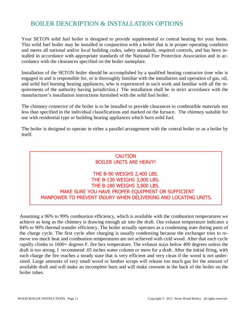
Your SETON solid fuel boiler is designed to provide supplemental or central heating for your home. This solid fuel boiler may be installed in conjunction with a boiler that is in proper operating condition and meets all national and/or local building codes, safety standards, required controls, and has been in-stalled in accordance with appropriate standards of the National Fire Protection Association and in ac-cordance with the clearances specified on the boiler nameplate. Installation of the SETON boiler should be accomplished by a qualified heating contractor (one who is engaged in and is responsible for, or is thoroughly familiar with the installation and operation of gas, oil, and solid fuel burning heating appliances, who is experienced in such work and familiar with all the re-quirements of the authority having jurisdiction.) The installation shall be in strict accordance with the manufacturer’s installation instructions furnished with the solid fuel boiler. The chimney connector of the boiler is to be installed to provide clearances to combustible materials not less than specified in the individual classifications and marked on the furnace. The chimney suitable for use with residential type or building heating appliances which burn solid fuel. The boiler is designed to operate in either a parallel arrangement with the central boiler or as a boiler by itself.
BOILER DESCRIPTION & INSTALLATION OPTIONS
CAUTION BOILER UNITS ARE HEAVY!
THE B-90 WEIGHS 2,400 LBS. THE B-130 WEIGHS 3,000 LBS. THE B-180 WEIGHS 3,800 LBS.
MAKE SURE YOU HAVE PROPER EQUIPMENT OR SUFFICIENT MANPOWER TO PREVENT INJURY WHEN DELIVERING AND LOCATING UNITS.
Assuming a 96% to 99% combustion efficiency, which is available with the combustion temperatures we achieve as long as the chimney is drawing enough air into the draft. Our exhaust temperature indicates a 84% to 90% thermal transfer efficiency. The boiler actually operates as a condensing state during parts of the charge cycle. The first cycle after charging is usually condensing because the exchanger tries to re-move too much heat and combustion temperatures are not achieved with cold wood. After that each cycle rapidly climbs to 1600+ degrees F. fire box temperature. The exhaust stays below 400 degrees unless the draft is too strong. I recommend .05 inches water column or more for a draft. After the initial firing, with each charge the fire reaches a steady state that is very efficient and very clean if the wood is not under-sized. Large amounts of very small wood or lumber scraps will release too much gas for the amount of available draft and will make an incomplete burn and will make creosote in the back of the boiler on the boiler tubes.
WOOD BOILER INSTRUCTIONS Page 12 Copyright © 2011 Seton Wood Boilers all rights reserved
Before starting the installation of a new boiler and heating system it is beneficial to become informed about the boiler so that the proper unit is selected to properly supply your heating needs. Learning about boiler location, positioning and set-up before beginning installation will lead to a better, more efficient installation.
1. The installation of this boiler must comply with your local building code rulings. Do observe the clearances to combustibles. 2. Do not install this boiler in a mobile home or trailer. Install the boiler outside and pipe the hot water into the home. 3. Always connect this boiler to a chimney and vent to the outside. NEVER vent to another room or inside a building. 4. DO NOT CONNECT to an aluminum Type B gas vent. This is not safe. Use approved masonry or a UL 103 HT Listed Residential Type and Building Heating Appliance Chimney. Use an 8” diameter chimney that is high enough to provide required draft. DO NOT USE A CHIMNEY CAP . You can use a (China Cap) 5. Be sure that your chimney is safely constructed and in good repair. Have the chimney inspected by the fire department or a qualified inspector. 6. Inspect flue pipes, pipe joints, and flue pipe seals regularly to ensure that smoke and flue gasses are not drawn into and circulated by the air circulation system. 7. Cleanout of heat exchanger, flue pipe, chimney, and draft inducer (if used) is especially important at the end of the heating season. Accumulated ash may cause corrosion during the summer months. 8. Creosote or soot may build up in the chimney connector and chimney and cause a house/building fire. Inspect the chimney connector and chimney once monthly during the heating season and clean if necessary. 9. To prevent injury, do not allow anyone to use this boiler who is unfamiliar with the correct operation of the boiler. 10. Do not operate boiler while under the influence of drugs or alcohol. 11. For further information on using your furnace safely, obtain a copy of the National Fire Protection Association (NFPA) publication, “Using Coal and Wood Furnaces Safely” NFPA No,. HS-10-1978. The ad-dress of the NFPA is: Battery March Park, Quincy, MA 02269. 12. Ashes should not be allowed to accumulate higher than the draft holes. Dispose of ashes in a metal container with a tight-fitting lid. Keep the closed container on a noncombustible floor or on the ground, well away from all combustible materials. Keep the ashes in the closed container until all cinders have thoroughly cooled. The ashes may be buried in the ground or picked up by a refuse collector. 13. Paint discoloration will occur if boiler is over-fired. 14. This boiler has a painted surface which is durable but it will not stand rough handling or abuse. When installing your boiler, use care in handling. Clean with soap and water when boiler is not hot. 15. While boiler is in operation, all persons, especially young children should be alerted to the hazards from high surface temperatures and should be kept away to avoid burns or clothing ignition. Small children should be carefully supervised when they are in the same room with the boiler. 16. Keep boiler area clear and free from all combustible materials, gasoline, and other flammable vapors and liquids. 17. To prevent burns, always wear protective clothing, leather hearth gloves and eye protection, while tending the fire. 18. While in operation, keep the feed door, ash door, and cabinet door closed and secured at all times ex-cept while tending the fire.
BOILER INSTALLATION
WOOD BOILER INSTRUCTIONS Page 13 Copyright © 2011 Seton Wood Boilers all rights reserved
NOTE: Installation should be made by a qualified heating equipment installer (one who is engaged in
and is responsible for, or is thoroughly familiar with the installation and operation of gas, oil, and solid fuel burn-ing heating appliances, who is experienced in such work and familiar with all the building requirements and/or fire codes of the authority having local jurisdiction.) 1. The installation is to be completed in accordance with National Fire Protection Association NFPA) installation
standards No. 89M, 90B, 211, 70 (National Electrical Code) and Uniform Mechanical Code 913, 6-4 in states where applicable (where code offers making flue pipe connections into an existing chimney with other fuel burning appliances).
2. Wood-burning appliances need air for combustion and circulation to the house. Provision must be made to pro-
vide make-up air so as not to starve the central heating system of combustion air. Have the local regulating authority determine that make-up air supply is adequate. Reference NFPA standards No. 30 & 54, Code for Installation of Gas and Oil Equipment.
3. Position the boiler according to clearances (see page 4) 4. Make flue pipe connections to the chimney with 24-gauge pipe and elbows (not included with boiler) maintain-
ing proper clearances. Seal the flue pipe in the chimney with furnace cement. Chimney connections must be securely supported and joints fastened with sheet metal screws or rivets. 5. Make electrical supply connections in the electrical junction box and connect power supply wires to des-ignated wires using wire nuts (see wiring diagram page 19 & 21) The power cord supplied may be used for in-stallation if local codes and regulations permit. If not permitted, power supply wiring must be minimum of 18-ga. AWG copper and rated for 90 deg. Centigrade installed in a metal cable or conduit. Power connections should be made by a qualified installer to comply with NFPA Standard No. 70 and all local codes and regulations.
CAUTION: Keep furnishings and other combustible materials away from the boiler.
BOILER INSTALLATION
ANTIFREEZE, Do no install antifreeze in the boiler for a few weeks, in case of boiler problems that would blow the antifreeze out. Also it is best to drain the boiler at least three times with hot water in it to remove any residual oil or impurities in it. PRESSURE RELIEF VALVE (POP-OFF), The relief valve must be exercised at least once a year, to prevent chemical buildup in the valve that will prevent it from operating properly. Replace the relieve valve immediately if it starts to leak or drip. Never block relieve valves. Relieve valves should have an air gap so you can see if they are leaking. Drain lines must slope down so they do not collect water and to prevent freezing.
WOOD BOILER INSTRUCTIONS Page 14 Copyright © 2011 Seton Wood Boilers all rights reserved
The boiler must be placed on noncombustible floor solid concrete or masonry floor is preferable. Observe the clearances to combustible materials. The boiler must have its own flue. Do not Connect this unit to a chimney flue serving other appli-ances. Install exhaust pipe, elbows, and thimble as required, utilizing either a recently cleaned and inspected 8”
masonry chimney or an 8” I.D. class - A listed chimney. THE ONLY APPROVED CHIMNEY CAP IS THE CHINA HAT TYPE OF CHIMNEY CAP.
Use 8” round stove pipe. Secure each pipe section and/or elbow joint with three (3) sheet metal screws
per joint to firmly hold the sections together. Re-check clearances from the boiler, connector stove pipe, and corner clearances using the illustrations in
your local building codes or fire protection ordinances. DO NOT install this boiler in a mobile home or trailer. The clearances provided are minimum dimensions determined by the manufacturer’s testing facility. In-
stallation of this boiler must comply with the latest edition of NFPA 211 for reduced clearances and/or your local building code rulings (use whichever minimum dimensions are LARGEST).
BOILER LOCATION
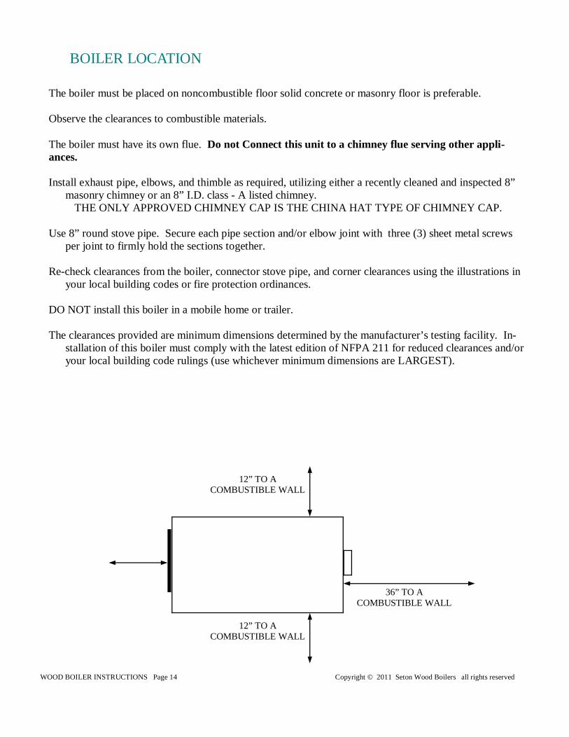
12” TO A COMBUSTIBLE WALL
12” TO A COMBUSTIBLE WALL
36” TO A COMBUSTIBLE WALL
WOOD BOILER INSTRUCTIONS Page 15 Copyright © 2011 Seton Wood Boilers all rights reserved
CHIMNEY DRAFT: The Seton Boiler is designed to burn wood without creating creosote; you can get a dirty burn by not having enough draft. This is normally caused by a poor chimney or burning small pieces of wood which releases more gas than the draft can produce oxygen for. Do not expect the boiler to draw. Draft is a function of the chimney, not the boiler. Smoke spillage into the house or excessive buildup of condensation or soot in the chimney are warnings that the chimney is NOT functioning properly. Correct the prob-lem before using the boiler. Following are some possible causes for improper draft. 1. Do not push the connector stove pipe into the chimney too far; it will plug the chimney and stop the draft. DO NOT USE A CHIMNEY CAP. 2. If the chimney is operating too cool, water will condense in the chimney and run back into the boiler. Soot formation will be rapid and may block the chimney. Operate the boiler at a high enough fire level to keep the chimney warm, preventing this condensation. Water temperature control should be set at 180°. 3. If the fire burns well but sometimes smokes or burns slowly, it may be caused by the chimney top being lower than an-other part of the house or a nearby tree. The wind blowing over a house or tree, falls on top of the chimney like water over a dam, beating down the smoke. The top of the chimney should be at least three (3) feet above the roof and be at least two (2) feet higher than any point of the roof within ten (10) feet.
NOTE: A draft reading of 0.06 to 0.07 W.C. (Water Column) is required for proper burning of this boiler.
CREOSOTE - Formation and Removal When wood is burned slowly, it produces tar and other organic vapors which combine with expelled moisture to form creo-sote. The creosote vapors condense in the relatively cool chimney flue of a slow-burning fire. As a result, creosote residue accumulates on the flue lining. If ignited, this creosote creates an extremely hot fire which may ignite surrounding materials resulting in a building fire. The chimney connector and chimney should be inspected at least once a month during the heating season to determine if a creosote buildup has occurred. If creosote has accumulated, it should be removed. Failure to remove creosote may result in ignition and may cause a house/building fire. Creosote may be removed using a chimney brush or other commonly available materials from your local hard-ware retailer. Chimney fires burn very hot. If the chimney connector should glow red, immediately call the fire department, then reduce the fire by closing the inlet air control and pour a large quantity of coarse salt, baking soda, or cool ashes on top of the fire in the firebox.
CAUTION: A chimney fire may cause ignition of wall studs or rafters which were assumed to be a safe distance from the chimney.
If a chimney fire has occurred, have your chimney inspected by a qualified person before using again.
CHIMNEY MAINTENANCE
NOTE: Any chimney that has been used before should be inspected by a qualified person be-fore this boiler is connected to it
WOOD BOILER INSTRUCTIONS Page 16 Copyright © 2011 Seton Wood Boilers all rights reserved
CHIMNEY MAINTENANCE
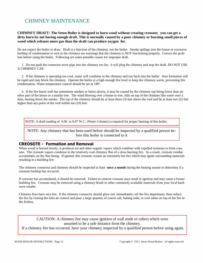
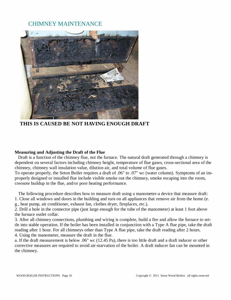
Measuring and Adjusting the Draft of the Flue Draft is a function of the chimney flue, not the furnace. The natural draft generated through a chimney is dependent on several factors including chimney height, temperature of flue gases, cross-sectional area of the chimney, chimney wall insulation value, dilution air, and total volume of flue gases. To operate properly, the Seton Boiler requires a draft of .06" to .07" wc (water column). Symptoms of an im-properly designed or installed flue include visible smoke out the chimney, smoke escaping into the room, creosote buildup in the flue, and/or poor heating performance. The following procedure describes how to measure draft using a manometer-a device that measure draft: 1. Close all windows and doors in the building and turn on all appliances that remove air from the home (e.g., heat pump, air conditioner, exhaust fan, clothes dryer, fireplaces, etc.). 2. Drill a hole in the connector pipe (just large enough for the tube of the manometer) at least 1 foot above the furnace outlet collar. 3. After all chimney connections, plumbing and wiring is complete, build a fire and allow the furnace to set-tle into stable operation. If the boiler has been installed in conjunction with a Type A flue pipe, take the draft reading after 1 hour. For all chimneys other than Type A flue pipe, take the draft reading after 2 hours. 4. Using the manometer, measure the draft in the flue. a. If the draft measurement is below .06" wc (12.45 Pa), there is too little draft and a draft inducer or other corrective measures are required to avoid air-starvation of the boiler. A draft inducer fan can be mounted in the chimney.
THIS IS CAUSED BE NOT HAVING ENOUGH DRAFT
WOOD BOILER INSTRUCTIONS Page 17 Copyright © 2011 Seton Wood Boilers all rights reserved
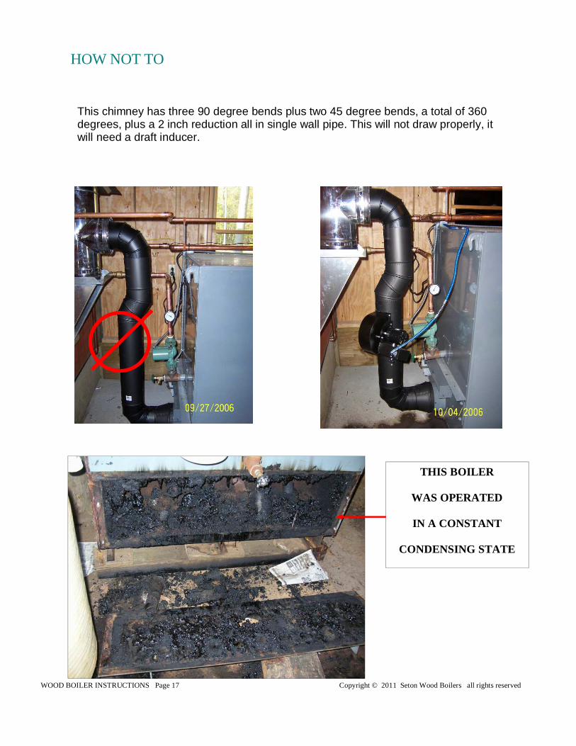
This chimney has three 90 degree bends plus two 45 degree bends, a total of 360 degrees, plus a 2 inch reduction all in single wall pipe. This will not draw properly, it will need a draft inducer.
HOW NOT TO
THIS BOILER
WAS OPERATED
IN A CONSTANT
CONDENSING STATE
WOOD BOILER INSTRUCTIONS Page 18 Copyright © 2011 Seton Wood Boilers all rights reserved
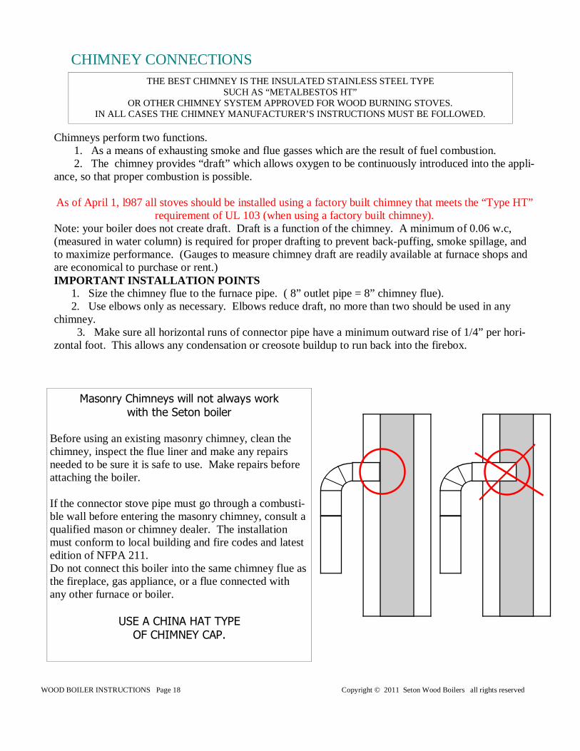
Chimneys perform two functions. 1. As a means of exhausting smoke and flue gasses which are the result of fuel combustion. 2. The chimney provides “draft” which allows oxygen to be continuously introduced into the appli-ance, so that proper combustion is possible. As of April 1, l987 all stoves should be installed using a factory built chimney that meets the “Type HT”
requirement of UL 103 (when using a factory built chimney). Note: your boiler does not create draft. Draft is a function of the chimney. A minimum of 0.06 w.c, (measured in water column) is required for proper drafting to prevent back-puffing, smoke spillage, and to maximize performance. (Gauges to measure chimney draft are readily available at furnace shops and are economical to purchase or rent.) IMPORTANT INSTALLATION POINTS 1. Size the chimney flue to the furnace pipe. ( 8” outlet pipe = 8” chimney flue). 2. Use elbows only as necessary. Elbows reduce draft, no more than two should be used in any chimney. 3. Make sure all horizontal runs of connector pipe have a minimum outward rise of 1/4” per hori-zontal foot. This allows any condensation or creosote buildup to run back into the firebox.
Masonry Chimneys will not always work with the Seton boiler
Before using an existing masonry chimney, clean the chimney, inspect the flue liner and make any repairs needed to be sure it is safe to use. Make repairs before attaching the boiler. If the connector stove pipe must go through a combusti-ble wall before entering the masonry chimney, consult a qualified mason or chimney dealer. The installation must conform to local building and fire codes and latest edition of NFPA 211. Do not connect this boiler into the same chimney flue as the fireplace, gas appliance, or a flue connected with any other furnace or boiler.
USE A CHINA HAT TYPE OF CHIMNEY CAP.
CHIMNEY CONNECTIONS THE BEST CHIMNEY IS THE INSULATED STAINLESS STEEL TYPE
SUCH AS “METALBESTOS HT” OR OTHER CHIMNEY SYSTEM APPROVED FOR WOOD BURNING STOVES.
IN ALL CASES THE CHIMNEY MANUFACTURER’S INSTRUCTIONS MUST BE FOLLOWED.
WOOD BOILER INSTRUCTIONS Page 19 Copyright © 2011 Seton Wood Boilers all rights reserved
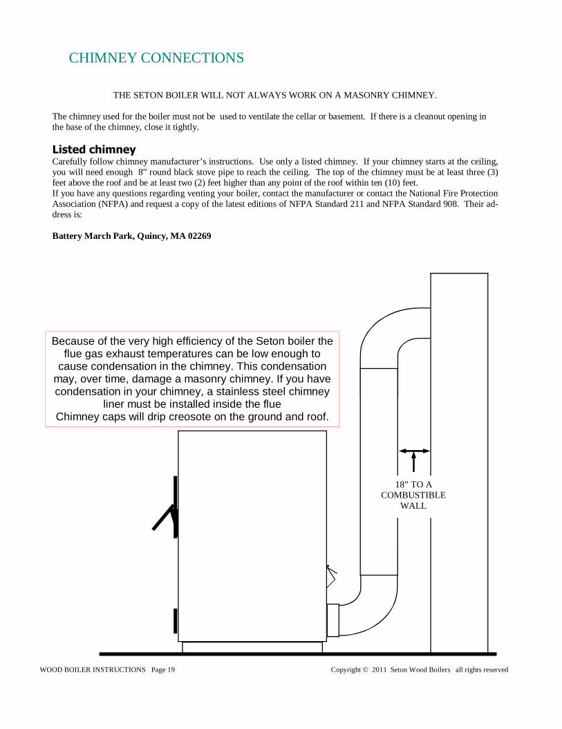
THE SETON BOILER WILL NOT ALWAYS WORK ON A MASONRY CHIMNEY. The chimney used for the boiler must not be used to ventilate the cellar or basement. If there is a cleanout opening in the base of the chimney, close it tightly. Listed chimney Carefully follow chimney manufacturer’s instructions. Use only a listed chimney. If your chimney starts at the ceiling, you will need enough 8” round black stove pipe to reach the ceiling. The top of the chimney must be at least three (3) feet above the roof and be at least two (2) feet higher than any point of the roof within ten (10) feet. If you have any questions regarding venting your boiler, contact the manufacturer or contact the National Fire Protection Association (NFPA) and request a copy of the latest editions of NFPA Standard 211 and NFPA Standard 908. Their ad-dress is: Battery March Park, Quincy, MA 02269
CHIMNEY CONNECTIONS
Because of the very high efficiency of the Seton boiler the flue gas exhaust temperatures can be low enough to
cause condensation in the chimney. This condensation may, over time, damage a masonry chimney. If you have condensation in your chimney, a stainless steel chimney
liner must be installed inside the flue Chimney caps will drip creosote on the ground and roof.
18” TO A COMBUSTIBLE
WALL
WOOD BOILER INSTRUCTIONS Page 20 Copyright © 2011 Seton Wood Boilers all rights reserved
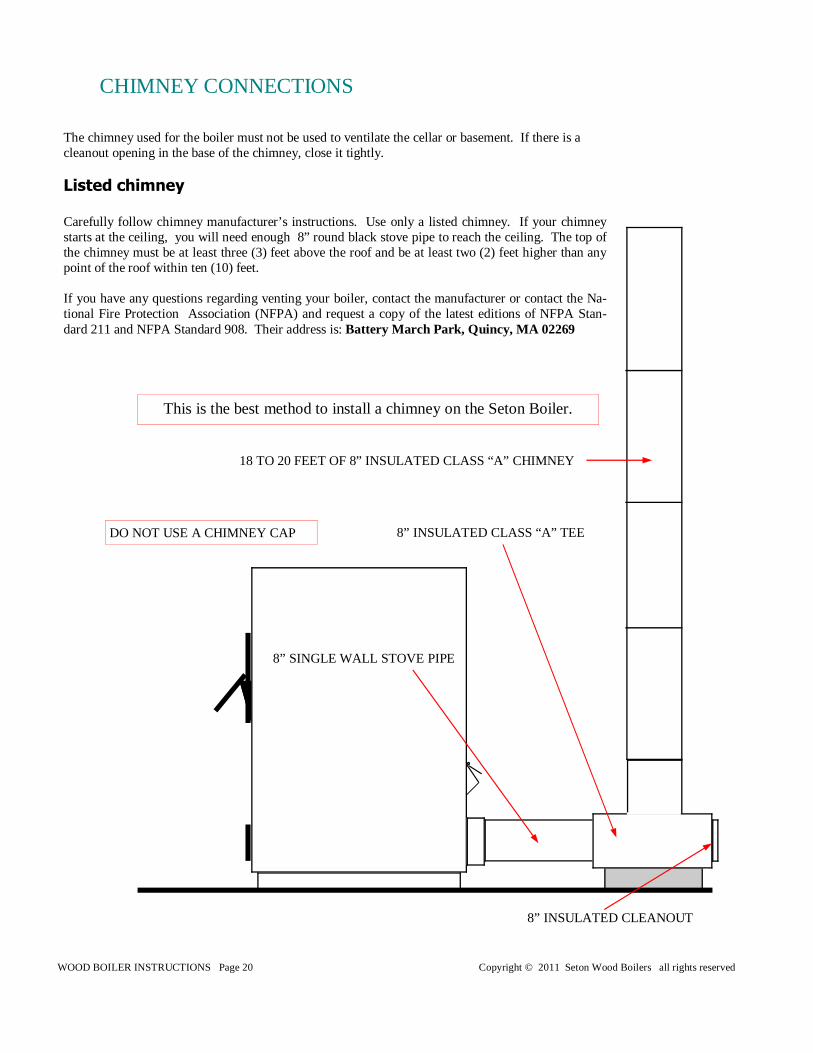
This is the best method to install a chimney on the Seton Boiler.
CHIMNEY CONNECTIONS
The chimney used for the boiler must not be used to ventilate the cellar or basement. If there is a cleanout opening in the base of the chimney, close it tightly. Listed chimney Carefully follow chimney manufacturer’s instructions. Use only a listed chimney. If your chimney starts at the ceiling, you will need enough 8” round black stove pipe to reach the ceiling. The top of the chimney must be at least three (3) feet above the roof and be at least two (2) feet higher than any point of the roof within ten (10) feet. If you have any questions regarding venting your boiler, contact the manufacturer or contact the Na-tional Fire Protection Association (NFPA) and request a copy of the latest editions of NFPA Stan-dard 211 and NFPA Standard 908. Their address is: Battery March Park, Quincy, MA 02269
8” SINGLE WALL STOVE PIPE
18 TO 20 FEET OF 8” INSULATED CLASS “A” CHIMNEY
8” INSULATED CLASS “A” TEE
8” INSULATED CLEANOUT
DO NOT USE A CHIMNEY CAP
WOOD BOILER INSTRUCTIONS Page 21 Copyright © 2011 Seton Wood Boilers all rights reserved
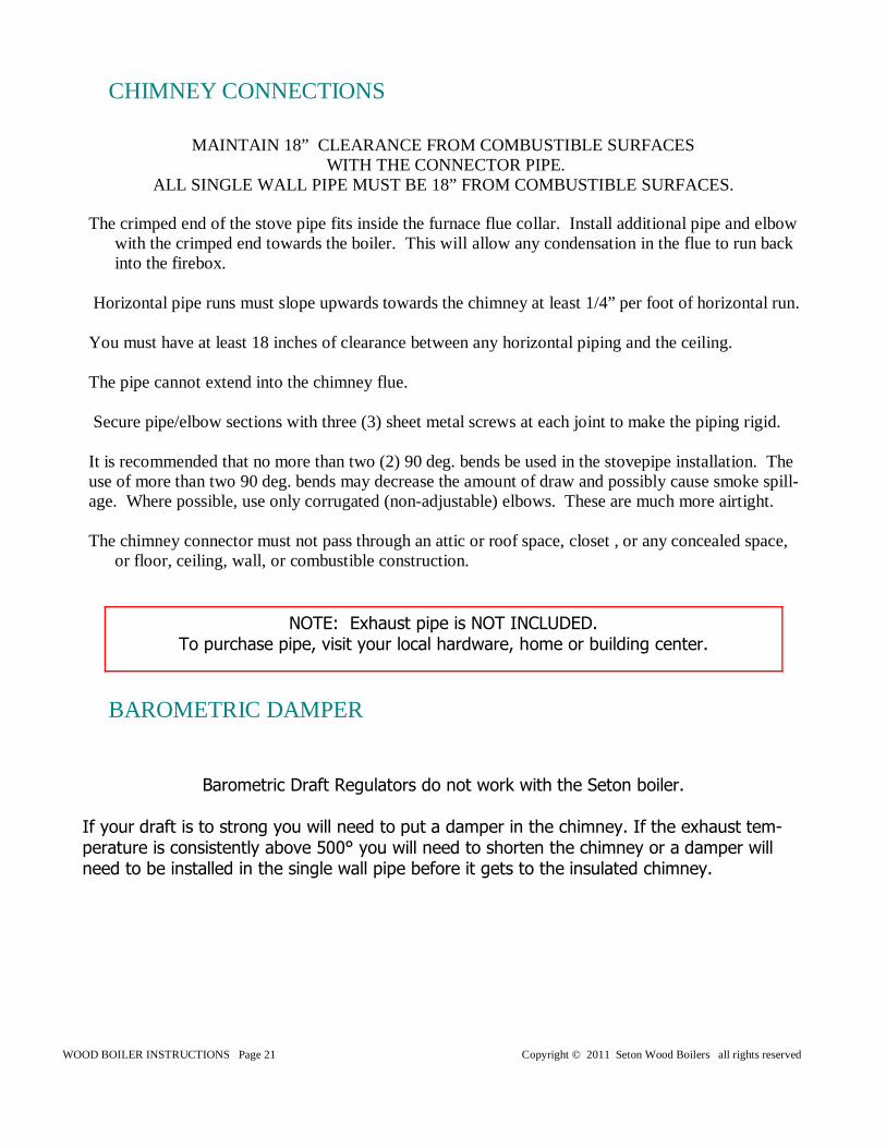
The crimped end of the stove pipe fits inside the furnace flue collar. Install additional pipe and elbow with the crimped end towards the boiler. This will allow any condensation in the flue to run back into the firebox.
Horizontal pipe runs must slope upwards towards the chimney at least 1/4” per foot of horizontal run. You must have at least 18 inches of clearance between any horizontal piping and the ceiling. The pipe cannot extend into the chimney flue. Secure pipe/elbow sections with three (3) sheet metal screws at each joint to make the piping rigid. It is recommended that no more than two (2) 90 deg. bends be used in the stovepipe installation. The use of more than two 90 deg. bends may decrease the amount of draw and possibly cause smoke spill-age. Where possible, use only corrugated (non-adjustable) elbows. These are much more airtight. The chimney connector must not pass through an attic or roof space, closet , or any concealed space,
or floor, ceiling, wall, or combustible construction.
NOTE: Exhaust pipe is NOT INCLUDED. To purchase pipe, visit your local hardware, home or building center.
Barometric Draft Regulators do not work with the Seton boiler. If your draft is to strong you will need to put a damper in the chimney. If the exhaust tem-perature is consistently above 500° you will need to shorten the chimney or a damper will need to be installed in the single wall pipe before it gets to the insulated chimney.
CHIMNEY CONNECTIONS
BAROMETRIC DAMPER
MAINTAIN 18” CLEARANCE FROM COMBUSTIBLE SURFACES WITH THE CONNECTOR PIPE.
ALL SINGLE WALL PIPE MUST BE 18” FROM COMBUSTIBLE SURFACES.
WOOD BOILER INSTRUCTIONS Page 22 Copyright © 2011 Seton Wood Boilers all rights reserved
CAUTION: HOUSE FIRE HAZARDS • Gasses emitted from freshly added fuel must be burned or they will cause creosote to accumulate in the
chimney. Never smother a fire when adding fresh fuel. • Never use COAL as a fuel in this boiler. It is not designed to burn any type of coal or coal fuel products.
• DOOR IS HOT while in operation. Keep children, clothing, and furniture away. Contact may cause skin burns.
WARNING: Explosion Hazard
• Never use chemicals, gasoline, gasoline-type lantern fuel, kerosene, charcoal lighter fluid, or similar flam-
mable liquids to start or “freshen-up” a fire in the boiler. • Keep all flammable liquids, especially gasoline, out of the vicinity of the boiler—whether in use or in stor-
age. • Inspect and clean flue pipe every 90 days. Replace immediately if flue pipe is rusting or leaking smoke
into the room. • Do not operate boiler with a draft less than 0.05” W.C. (water column)
WARNINGS
NEVER BLOCK DRAFT IN OPEN POSITION NEVER OPERATE WITH FEED DOOR OPEN
ANTIFREEZE, Do no install antifreeze in the boiler for a few weeks, in case of boiler problems that would blow the antifreeze out. Also it is best to drain the boiler at least three times with hot water in it to remove any residual oil or impurities in it. PRESSURE RELIEF VALVE (POP-OFF), The relief valve must be exercised at least once a year, to prevent chemical buildup in the valve that will prevent it from operating properly. Replace the relieve valve immediately if it starts to leak or drip. Never block relieve valves. Relieve valves should have an air gap so you can see if they are leaking. Drain lines must slope down so they do not collect water and to prevent freezing.
Do not open the feed door until the wood has burned down some. Avoid trying to see how the fire is burning right after you fill it.
All wood burning appliances will smoke if you open the feed door when it is full of wood.
Do not over-fire the boiler. Over-firing will occur if the feed door is left open
or the draft is blocked open during operation. Such actions can result in very dangerous operating conditions.
WOOD BOILER INSTRUCTIONS Page 23 Copyright © 2011 Seton Wood Boilers all rights reserved
FUELS Do not burn garbage or flammable fluids. Do not burn tires or treated wood or wood with heavy creosote in it. Store wood in dry, well-ventilated area. Round un-split blocks work best LIGHTING 1. Open the feed door and place paper and kindling on the back of fire box. 2. Light fire, close and secure the feed door. A small amount of charcoal starter will help. 3. Add wood after fire is burning briskly. Use care not to smother the kindling fire when adding wood. ADDING FUEL Push coals to back before putting fuel in. Try to let fire burn down before refilling, to prevent too much smoke escaping from the door. When adding fuel put logs in crosswise, place logs on door frame and roll into the fire box. Do not put logs into firebox that are longer than the door opening. Do not put logs in end first; it can damage the refrac-tory. Add fresh kindling if the bed of coals are gone. Normally you can just stir the coals and put the wood in. Empty ash regularly. Do not allow ashes to pile up over the draft holes. If ashes build above the draft
holes it will restrict the air flow and cause a dirty burn. OPERATING SAFETY PRECAUTIONS 1. Never over-fire. If boiler stovepipe begins to glow or turn red, you are over firing the boiler. 3. HOT while in operation. Keep children, clothing, and furniture away. Contact may cause skin burns.
Do not touch the boiler after firing until it has cooled. 4. Provide make-up air into the room for proper combustion.
FUELS AND LOADING
WOOD BOILER INSTRUCTIONS Page 24 Copyright © 2011 Seton Wood Boilers all rights reserved
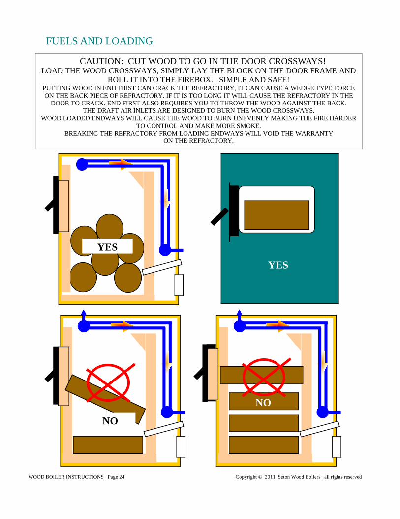
CAUTION: CUT WOOD TO GO IN THE DOOR CROSSWAYS! LOAD THE WOOD CROSSWAYS, SIMPLY LAY THE BLOCK ON THE DOOR FRAME AND
ROLL IT INTO THE FIREBOX. SIMPLE AND SAFE! PUTTING WOOD IN END FIRST CAN CRACK THE REFRACTORY, IT CAN CAUSE A WEDGE TYPE FORCE ON THE BACK PIECE OF REFRACTORY. IF IT IS TOO LONG IT WILL CAUSE THE REFRACTORY IN THE
DOOR TO CRACK. END FIRST ALSO REQUIRES YOU TO THROW THE WOOD AGAINST THE BACK. THE DRAFT AIR INLETS ARE DESIGNED TO BURN THE WOOD CROSSWAYS.
WOOD LOADED ENDWAYS WILL CAUSE THE WOOD TO BURN UNEVENLY MAKING THE FIRE HARDER TO CONTROL AND MAKE MORE SMOKE.
BREAKING THE REFRACTORY FROM LOADING ENDWAYS WILL VOID THE WARRANTY ON THE REFRACTORY.
FUELS AND LOADING
YES
YES
NO
NO
WOOD BOILER INSTRUCTIONS Page 25 Copyright © 2011 Seton Wood Boilers all rights reserved
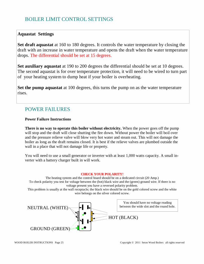
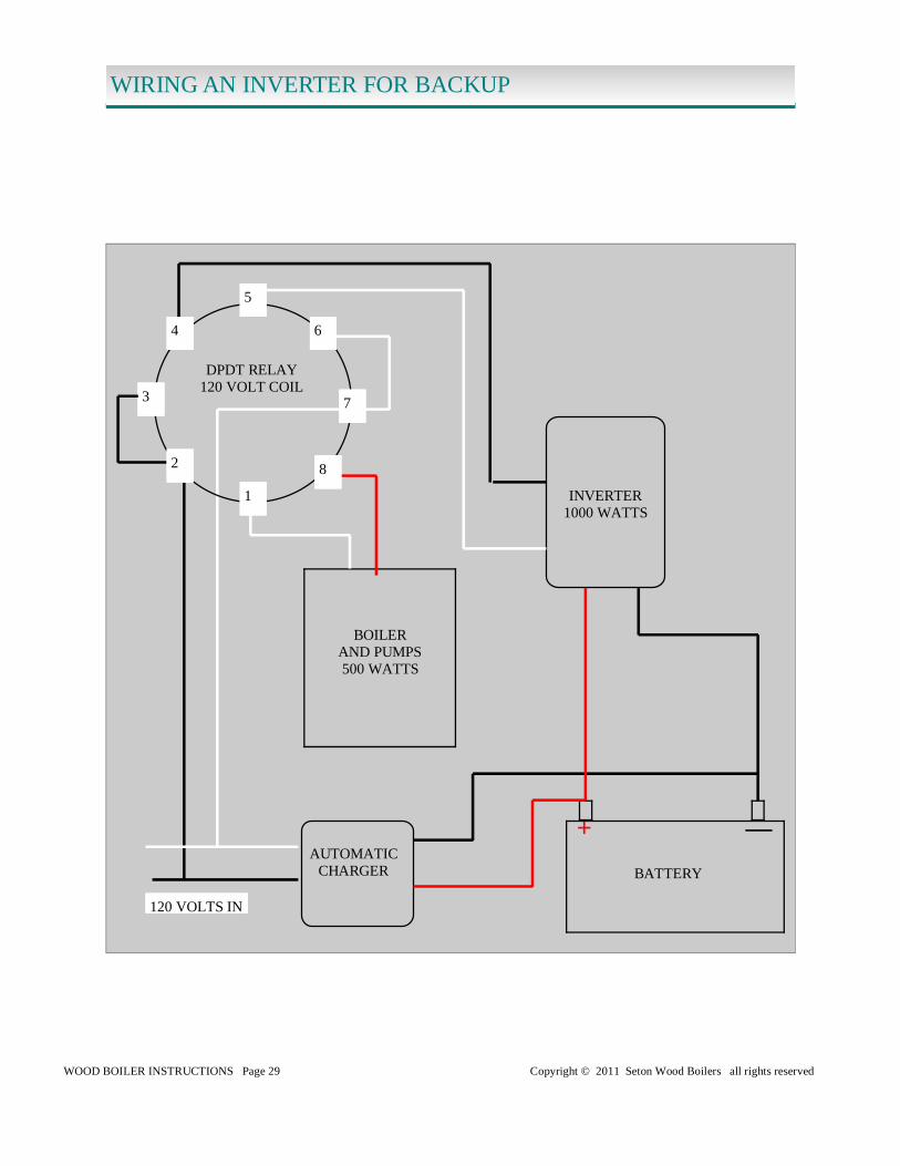
Power Failure Instructions There is no way to operate this boiler without electricity. When the power goes off the pump will stop and the draft will close shutting the fire down. Without power the boiler will boil over and the pressure relieve valve will blow very hot water and steam out. This will not damage the boiler as long as the draft remains closed. It is best if the relieve valves are plumbed outside the wall in a place that will not damage life or property. You will need to use a small generator or inverter with at least 1,000 watts capacity. A small in-verter with a battery charger built in will work.
POWER FAILURES
BOILER LIMIT CONTROL SETTINGS
Aquastat Settings Set draft aquastat at 160 to 180 degrees. It controls the water temperature by closing the draft with an increase in water temperature and opens the draft when the water temperature drops. The differential should be set at 15 degrees. Set auxiliary aquastat at 190 to 200 degrees the differential should be set at 10 degrees. The second aquastat is for over temperature protection, it will need to be wired to turn part of your heating system to dump heat if your boiler is overheating. Set the pump aquastat at 100 degrees, this turns the pump on as the water temperature rises.
CHECK YOUR POLARITY! The heating system and the control board should be on a dedicated circuit (20 Amp.)
To check polarity you test for voltage between the (hot) black wire and the (green) ground wire. If there is no voltage present you have a reversed polarity problem.
This problem is usually at the wall receptacle; the black wire should be on the gold colored screw and the white wire belongs on the silver colored screw.
NEUTRAL (WHITE)
HOT (BLACK)
GROUND (GREEN)
You should have no voltage reading between the wide slot and the round hole.
WOOD BOILER INSTRUCTIONS Page 26 Copyright © 2011 Seton Wood Boilers all rights reserved
WIRING DIAGRAM AQUASTAT OPERATION
R
B
W
DRAFT MOTOR
110 VOLTS
B W
DRAFT
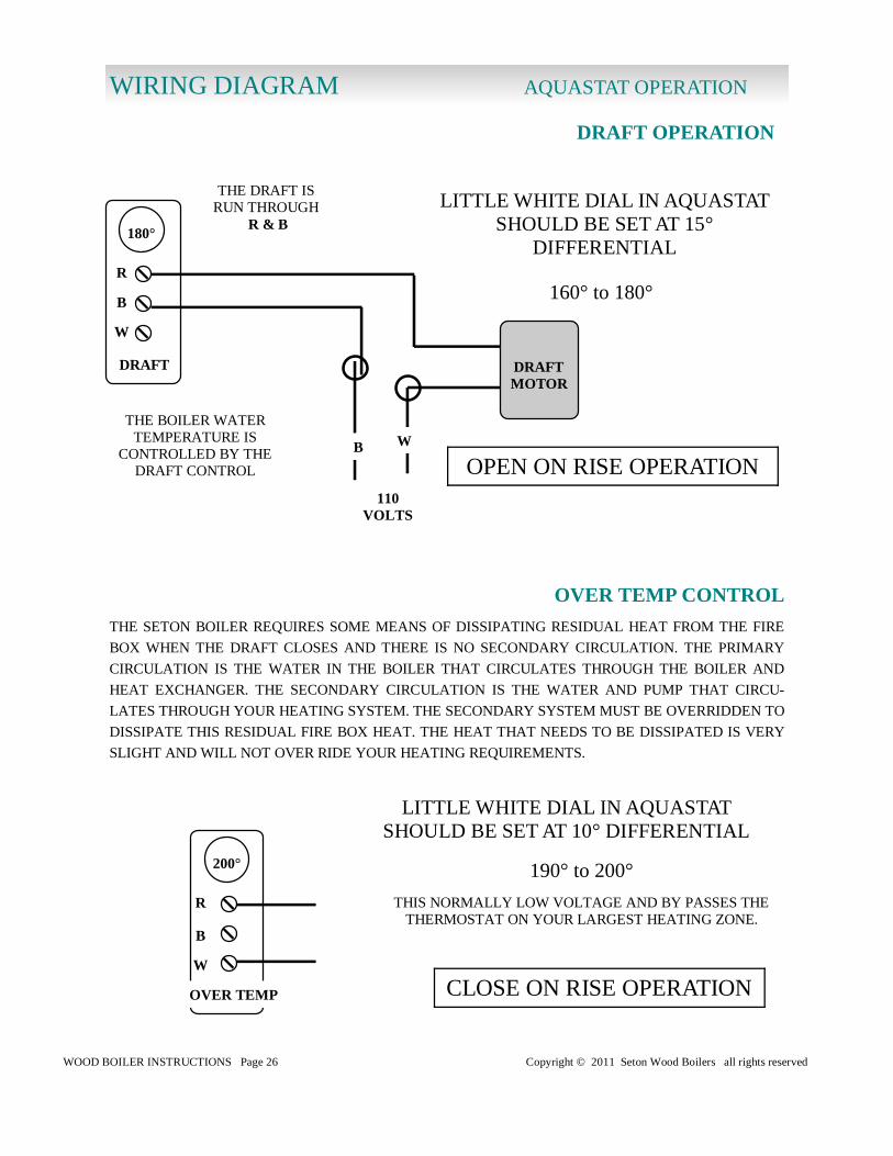
180°
THE BOILER WATER TEMPERATURE IS
CONTROLLED BY THE DRAFT CONTROL
LITTLE WHITE DIAL IN AQUASTAT SHOULD BE SET AT 15°
DIFFERENTIAL
THE DRAFT IS RUN THROUGH
R & B
DRAFT OPERATION
OPEN ON RISE OPERATION
R
B
W
OVER TEMP
200°
THE SETON BOILER REQUIRES SOME MEANS OF DISSIPATING RESIDUAL HEAT FROM THE FIRE
BOX WHEN THE DRAFT CLOSES AND THERE IS NO SECONDARY CIRCULATION. THE PRIMARY
CIRCULATION IS THE WATER IN THE BOILER THAT CIRCULATES THROUGH THE BOILER AND
HEAT EXCHANGER. THE SECONDARY CIRCULATION IS THE WATER AND PUMP THAT CIRCU-
LATES THROUGH YOUR HEATING SYSTEM. THE SECONDARY SYSTEM MUST BE OVERRIDDEN TO
DISSIPATE THIS RESIDUAL FIRE BOX HEAT. THE HEAT THAT NEEDS TO BE DISSIPATED IS VERY
SLIGHT AND WILL NOT OVER RIDE YOUR HEATING REQUIREMENTS.
CLOSE ON RISE OPERATION
LITTLE WHITE DIAL IN AQUASTAT SHOULD BE SET AT 10° DIFFERENTIAL
THIS NORMALLY LOW VOLTAGE AND BY PASSES THE THERMOSTAT ON YOUR LARGEST HEATING ZONE.
OVER TEMP CONTROL
160° to 180°
190° to 200°
WOOD BOILER INSTRUCTIONS Page 27 Copyright © 2011 Seton Wood Boilers all rights reserved
WIRING DIAGRAM AQUASTAT OPERATION
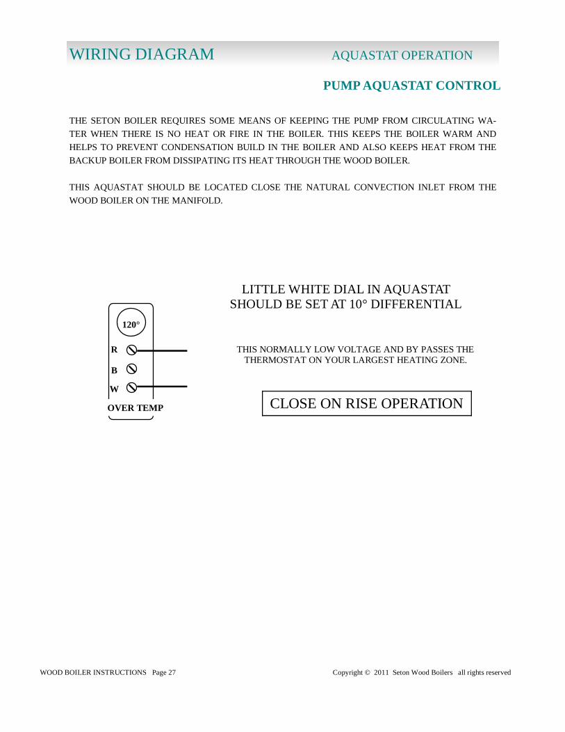
PUMP AQUASTAT CONTROL
R
B
W
OVER TEMP
120°
CLOSE ON RISE OPERATION
LITTLE WHITE DIAL IN AQUASTAT SHOULD BE SET AT 10° DIFFERENTIAL
THIS NORMALLY LOW VOLTAGE AND BY PASSES THE THERMOSTAT ON YOUR LARGEST HEATING ZONE.
THE SETON BOILER REQUIRES SOME MEANS OF KEEPING THE PUMP FROM CIRCULATING WA-
TER WHEN THERE IS NO HEAT OR FIRE IN THE BOILER. THIS KEEPS THE BOILER WARM AND
HELPS TO PREVENT CONDENSATION BUILD IN THE BOILER AND ALSO KEEPS HEAT FROM THE
BACKUP BOILER FROM DISSIPATING ITS HEAT THROUGH THE WOOD BOILER.
THIS AQUASTAT SHOULD BE LOCATED CLOSE THE NATURAL CONVECTION INLET FROM THE
WOOD BOILER ON THE MANIFOLD.
WOOD BOILER INSTRUCTIONS Page 28 Copyright © 2011 Seton Wood Boilers all rights reserved
W
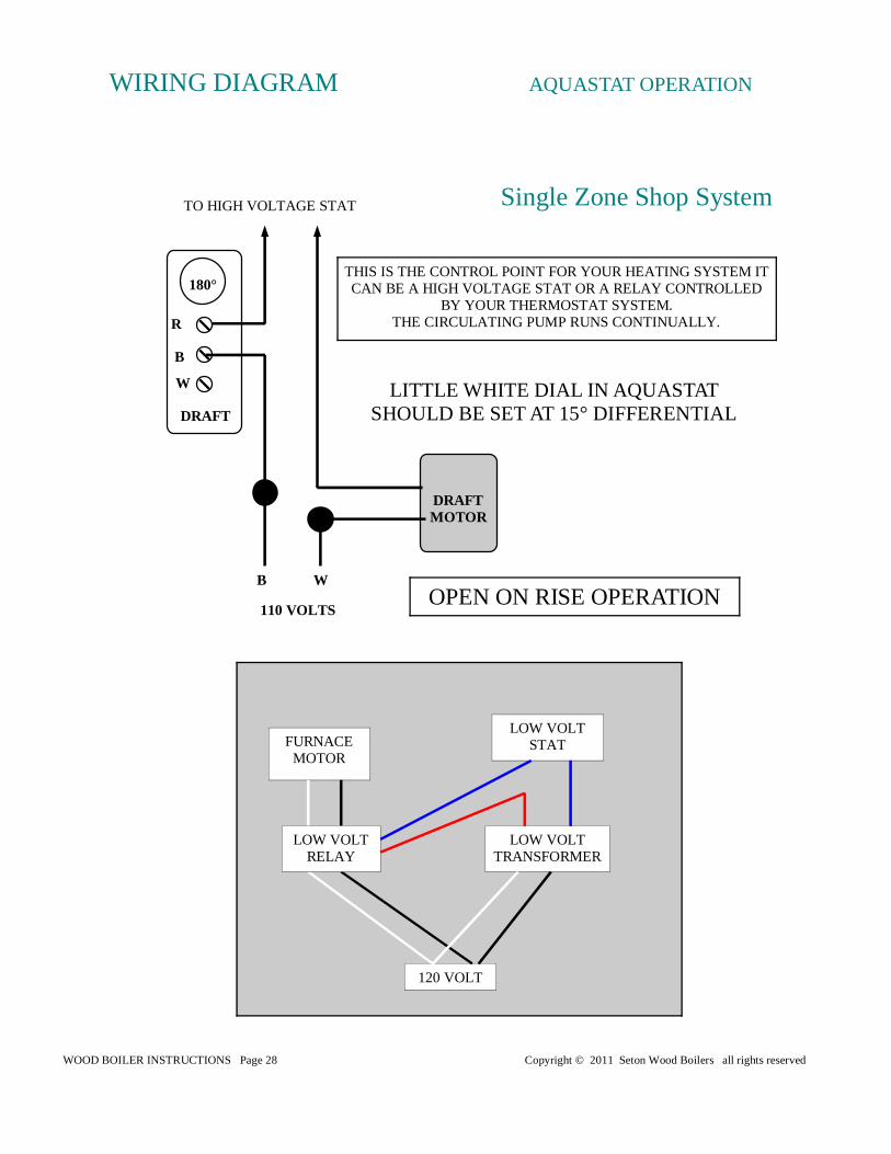
TO HIGH VOLTAGE STAT
THIS IS THE CONTROL POINT FOR YOUR HEATING SYSTEM IT CAN BE A HIGH VOLTAGE STAT OR A RELAY CONTROLLED
BY YOUR THERMOSTAT SYSTEM. THE CIRCULATING PUMP RUNS CONTINUALLY.
DRAFT MOTOR
110 VOLTS
B W
DRAFT
180°
R
B
WIRING DIAGRAM AQUASTAT OPERATION
Single Zone Shop System
OPEN ON RISE OPERATION
LITTLE WHITE DIAL IN AQUASTAT SHOULD BE SET AT 15° DIFFERENTIAL
FURNACE MOTOR
LOW VOLT STAT
LOW VOLT TRANSFORMER
120 VOLT
LOW VOLT RELAY
WOOD BOILER INSTRUCTIONS Page 29 Copyright © 2011 Seton Wood Boilers all rights reserved
PLUMBING RADIANT SYSTEM WIRING AN INVERTER FOR BACKUP
— +
DPDT RELAY 120 VOLT COIL
INVERTER 1000 WATTS
AUTOMATIC CHARGER BATTERY
BOILER AND PUMPS 500 WATTS
120 VOLTS IN
1
2
3
4
5
6
7
8
WOOD BOILER INSTRUCTIONS Page 30 Copyright © 2011 Seton Wood Boilers all rights reserved
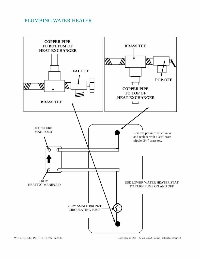
Remove pressure relief valve and replace with a 3/4” brass nipple, 3/4” brass tee.
PLUMBING WATER HEATER
POP-OFF
BRASS TEE
COPPER PIPE TO TOP OF
HEAT EXCHANGER
FAUCET
BRASS TEE
COPPER PIPE TO BOTTOM OF
HEAT EXCHANGER
VERY SMALL BRONZE CIRCULATING PUMP
FROM HEATING MANIFOLD
TO RETURN MANIFOLD
USE LOWER WATER HEATER STAT TO TURN PUMP ON AND OFF
WOOD BOILER INSTRUCTIONS Page 31 Copyright © 2011 Seton Wood Boilers all rights reserved
RETURN
RETURN
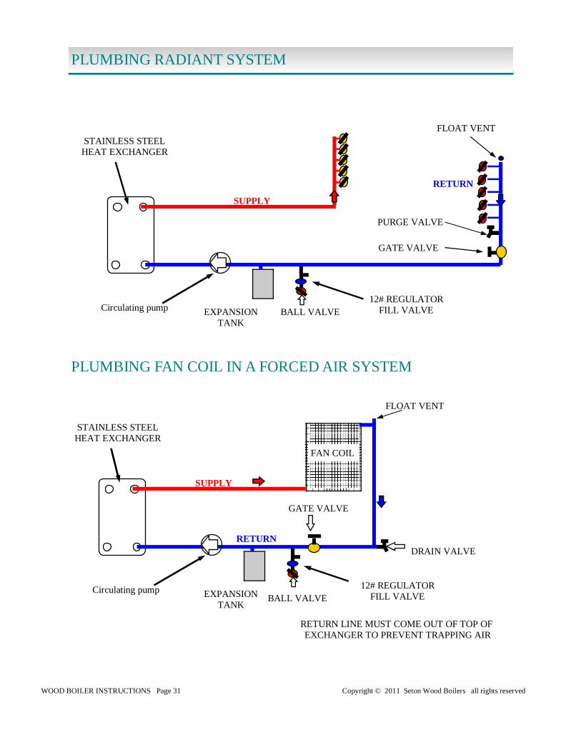
PLUMBING RADIANT SYSTEM
Circulating pump
Circulating pump
DRAIN VALVE
FAN COIL
PLUMBING FAN COIL IN A FORCED AIR SYSTEM
RETURN LINE MUST COME OUT OF TOP OF EXCHANGER TO PREVENT TRAPPING AIR
PLUMBING RADIANT SYSTEM
STAINLESS STEEL HEAT EXCHANGER
STAINLESS STEEL HEAT EXCHANGER
SUPPLY
SUPPLY
EXPANSION TANK
EXPANSION TANK
12# REGULATOR FILL VALVE
12# REGULATOR FILL VALVE BALL VALVE
BALL VALVE
FLOAT VENT
FLOAT VENT
PURGE VALVE
GATE VALVE
GATE VALVE
WOOD BOILER INSTRUCTIONS Page 32 Copyright © 2011 Seton Wood Boilers all rights reserved
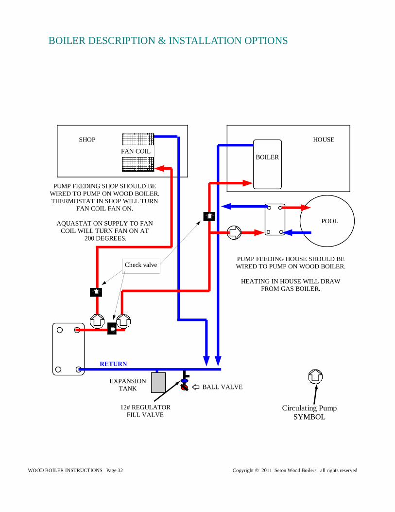
RETURN
BOILER DESCRIPTION & INSTALLATION OPTIONS
Circulating Pump SYMBOL
HOUSE SHOP
POOL
BOILER FAN COIL
PUMP FEEDING SHOP SHOULD BE WIRED TO PUMP ON WOOD BOILER. THERMOSTAT IN SHOP WILL TURN
FAN COIL FAN ON.
AQUASTAT ON SUPPLY TO FAN COIL WILL TURN FAN ON AT
200 DEGREES.
PUMP FEEDING HOUSE SHOULD BE WIRED TO PUMP ON WOOD BOILER.
HEATING IN HOUSE WILL DRAW
FROM GAS BOILER.
Check valve
EXPANSION TANK
12# REGULATOR FILL VALVE
BALL VALVE
WOOD BOILER INSTRUCTIONS Page 33 Copyright © 2011 Seton Wood Boilers all rights reserved
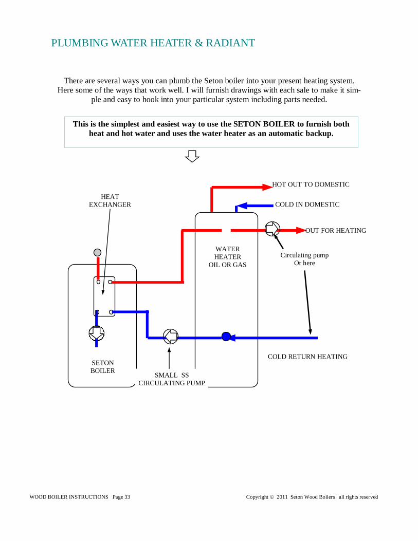
WATER HEATER
OIL OR GAS
Circulating pump Or here
SETON BOILER
SMALL SS CIRCULATING PUMP
HEAT EXCHANGER
HOT OUT TO DOMESTIC
COLD IN DOMESTIC
OUT FOR HEATING
COLD RETURN HEATING
There are several ways you can plumb the Seton boiler into your present heating system. Here some of the ways that work well. I will furnish drawings with each sale to make it sim-
ple and easy to hook into your particular system including parts needed.
This is the simplest and easiest way to use the SETON BOILER to furnish both heat and hot water and uses the water heater as an automatic backup.
PLUMBING WATER HEATER & RADIANT
WOOD BOILER INSTRUCTIONS Page 34 Copyright © 2011 Seton Wood Boilers all rights reserved
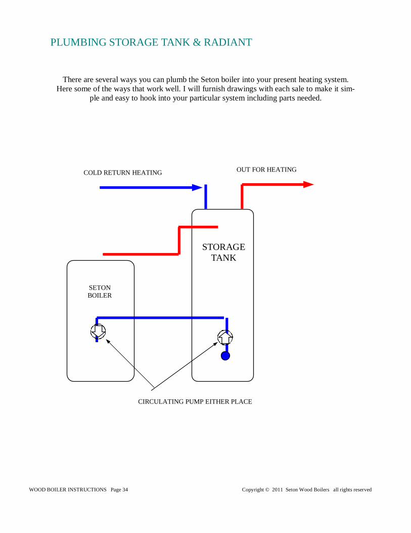
STORAGE TANK
SETON BOILER
CIRCULATING PUMP EITHER PLACE
OUT FOR HEATING COLD RETURN HEATING
There are several ways you can plumb the Seton boiler into your present heating system. Here some of the ways that work well. I will furnish drawings with each sale to make it sim-
ple and easy to hook into your particular system including parts needed.
PLUMBING STORAGE TANK & RADIANT
WOOD BOILER INSTRUCTIONS Page 35 Copyright © 2011 Seton Wood Boilers all rights reserved
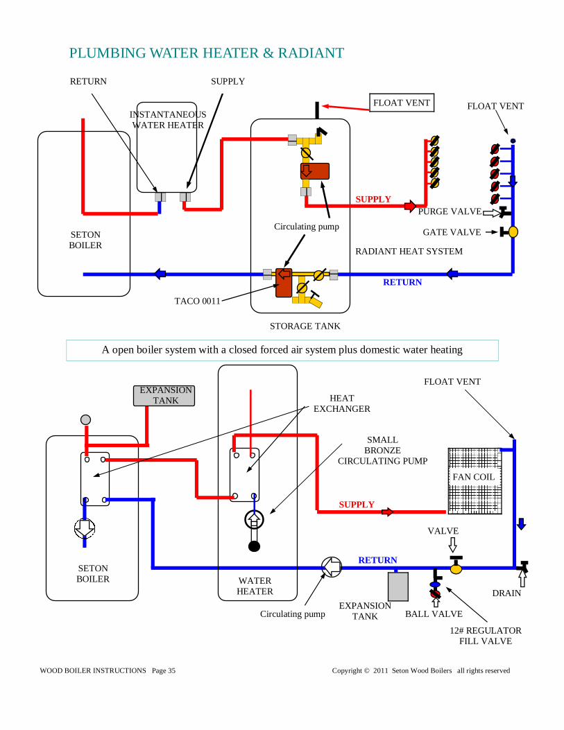
RETURN
A open boiler system with a closed forced air system plus domestic water heating
WATER HEATER
Circulating pump
SETON BOILER
SMALL BRONZE
CIRCULATING PUMP
HEAT EXCHANGER
DRAIN
VALVE
FAN COIL
INSTANTANEOUS WATER HEATER
Circulating pump
STORAGE TANK
FLOAT VENT
TACO 0011
FLOAT VENT
SETON BOILER
RADIANT HEAT SYSTEM
RETURN SUPPLY
PLUMBING WATER HEATER & RADIANT
SUPPLY
SUPPLY
RETURN
EXPANSION TANK
EXPANSION TANK
12# REGULATOR FILL VALVE
BALL VALVE
FLOAT VENT
PURGE VALVE
GATE VALVE
WOOD BOILER INSTRUCTIONS Page 36 Copyright © 2011 Seton Wood Boilers all rights reserved
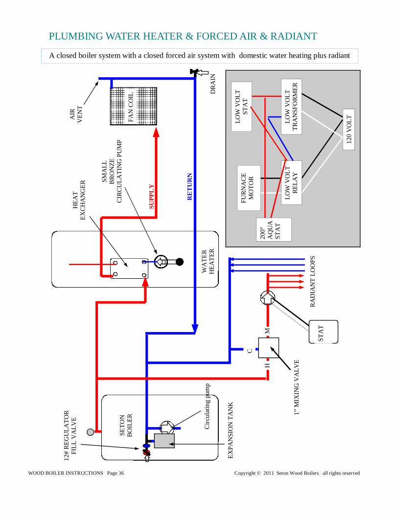
A closed boiler system with a closed forced air system with domestic water heating plus radiant
PLUMBING WATER HEATER & FORCED AIR & RADIANT
WA
TE
R
HE
AT
ER
C
ircu
latin
g pu
mp
SE
TO
N B
OIL
ER
SM
ALL
B
RO
NZ
E
CIR
CU
LAT
ING
PU
MP
HE
AT
E
XC
HA
NG
ER
DR
AIN
FA
N C
OIL
EX
PA
NS
ION
TA
NK
12#
RE
GU
LAT
OR
F
ILL
VA
LVE
SU
PP
LY
RE
TU
RN
AIR
V
EN
T
RA
DIA
NT
LO
OP
S
ST
AT
FU
RN
AC
E
MO
TO
R
LOW
VO
LT
ST
AT
LOW
VO
LT
TR
AN
SF
OR
ME
R
120
VO
LT
LOW
VO
LT
RE
LAY
200°
A
QU
A
ST
AT
M
C
H
1” M
IXIN
G V
ALV
E
WOOD BOILER INSTRUCTIONS Page 37 Copyright © 2011 Seton Wood Boilers all rights reserved
HIG
H
VO
LT
ST
AT
HIG
H
VO
LT
ST
AT
HIG
H
VO
LT
ST
AT
HIG
H
VO
LT
ST
AT
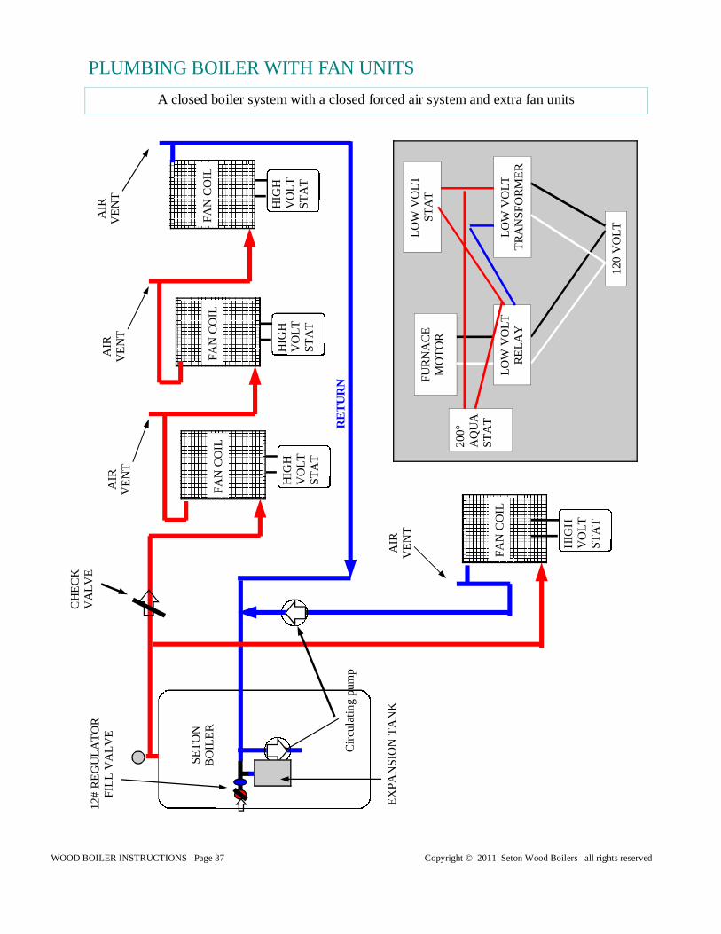
A closed boiler system with a closed forced air system and extra fan units
Cir
cula
ting
pum
p
SE
TO
N B
OIL
ER
CH
EC
K
VA
LVE
FA
N C
OIL
EX
PA
NS
ION
TA
NK
12#
RE
GU
LAT
OR
F
ILL
VA
LVE
RE
TU
RN
AIR
V
EN
T
FU
RN
AC
E
MO
TO
R
LOW
VO
LT
ST
AT
LOW
VO
LT
TR
AN
SF
OR
ME
R
120
VO
LT
LOW
VO
LT
RE
LAY
200°
A
QU
A
ST
AT
FA
N C
OIL
AIR
V
EN
T
FA
N C
OIL
AIR
V
EN
T
FA
N C
OIL
AIR
V
EN
T
PLUMBING BOILER WITH FAN UNITS
WOOD BOILER INSTRUCTIONS Page 38 Copyright © 2011 Seton Wood Boilers all rights reserved
RETURN
Circulating pump
Circulating pump
VALVE
DRAIN VALVE
FAN COIL
SETON BOILER
SETON BOILER
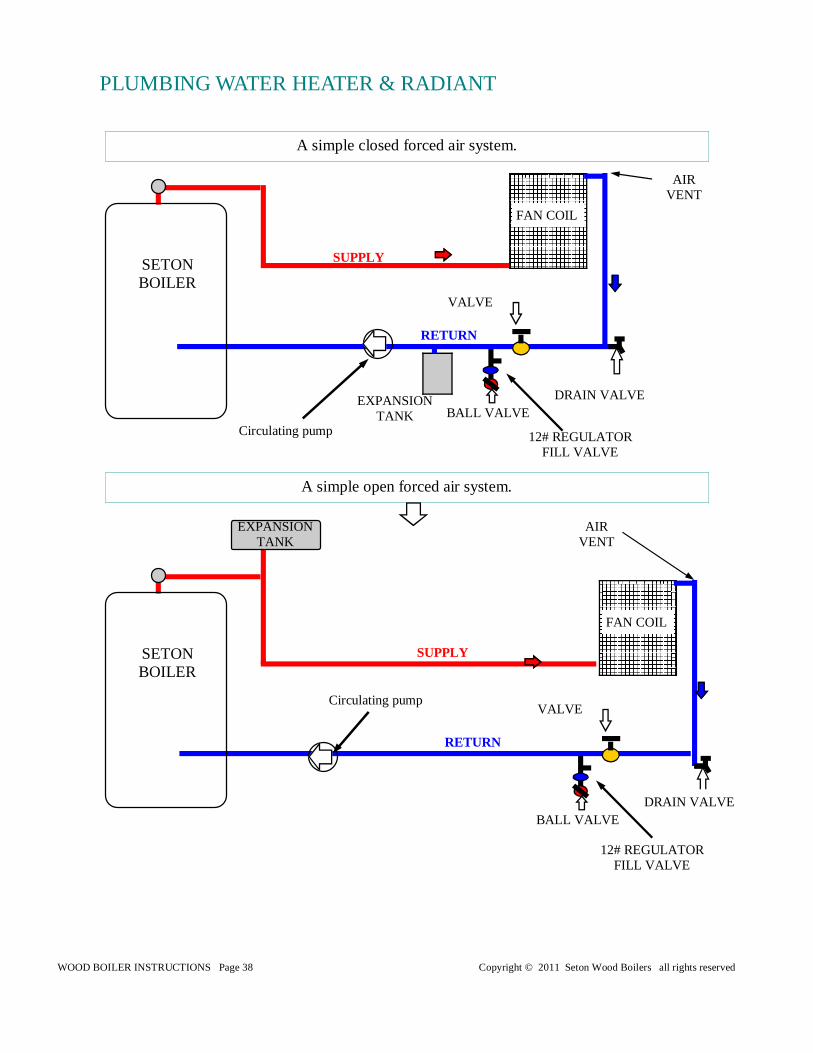
A simple closed forced air system.
A simple open forced air system.
VALVE
DRAIN VALVE
FAN COIL
PLUMBING WATER HEATER & RADIANT
AIR VENT
AIR VENT
SUPPLY
SUPPLY
RETURN
EXPANSION TANK
12# REGULATOR FILL VALVE
12# REGULATOR FILL VALVE
BALL VALVE
BALL VALVE
EXPANSION TANK
WOOD BOILER INSTRUCTIONS Page 39 Copyright © 2011 Seton Wood Boilers all rights reserved
RETURN
DRAIN VALVE
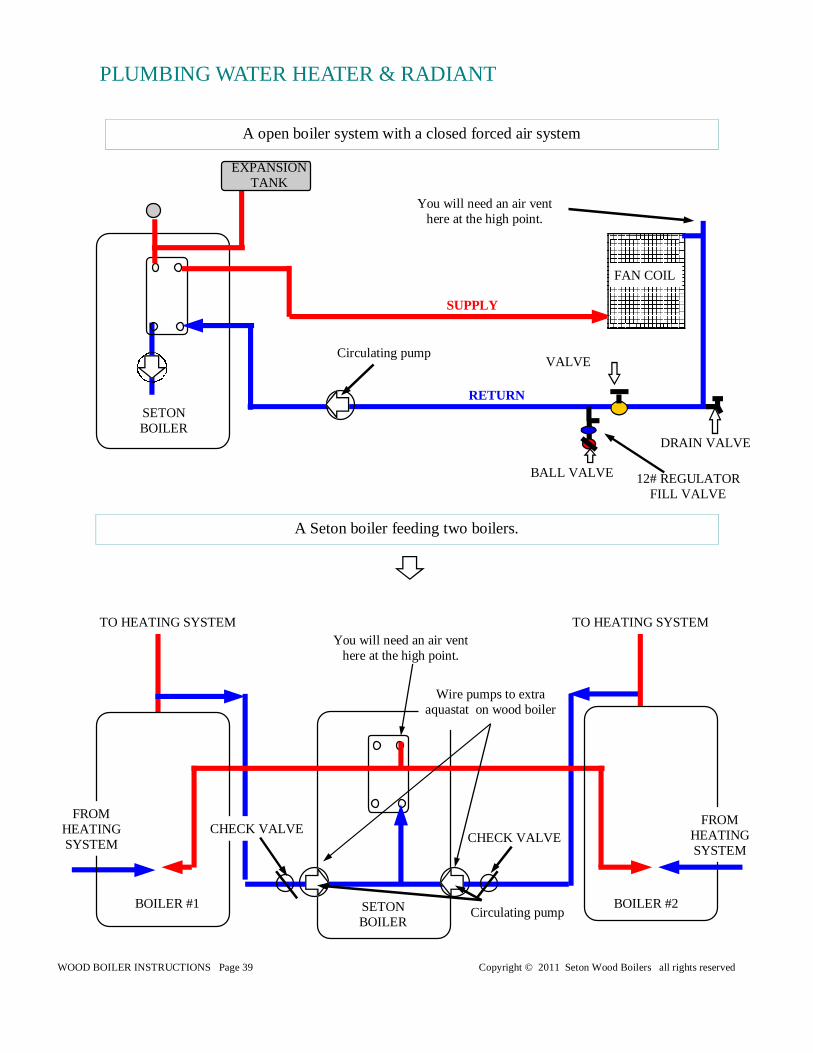
A open boiler system with a closed forced air system
SETON BOILER
Circulating pump VALVE
FAN COIL
SETON BOILER
Circulating pump BOILER #2 BOILER #1
CHECK VALVE CHECK VALVE
TO HEATING SYSTEM TO HEATING SYSTEM
FROM HEATING SYSTEM
FROM HEATING SYSTEM
A Seton boiler feeding two boilers.
You will need an air vent here at the high point.
Wire pumps to extra aquastat on wood boiler
PLUMBING WATER HEATER & RADIANT
You will need an air vent here at the high point.
SUPPLY
12# REGULATOR FILL VALVE
BALL VALVE
EXPANSION TANK
WOOD BOILER INSTRUCTIONS Page 40 Copyright © 2011 Seton Wood Boilers all rights reserved
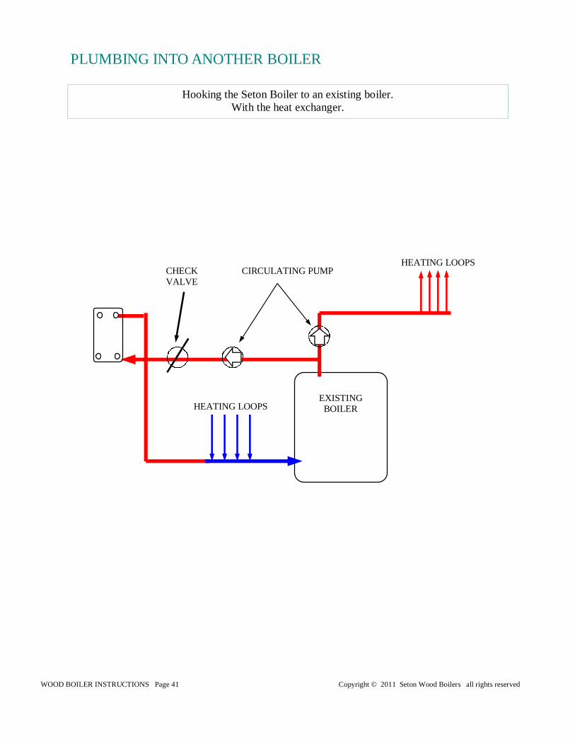
HEATING LOOPS
HEATING LOOPS
EXISTING BOILER
CIRCULATING PUMP
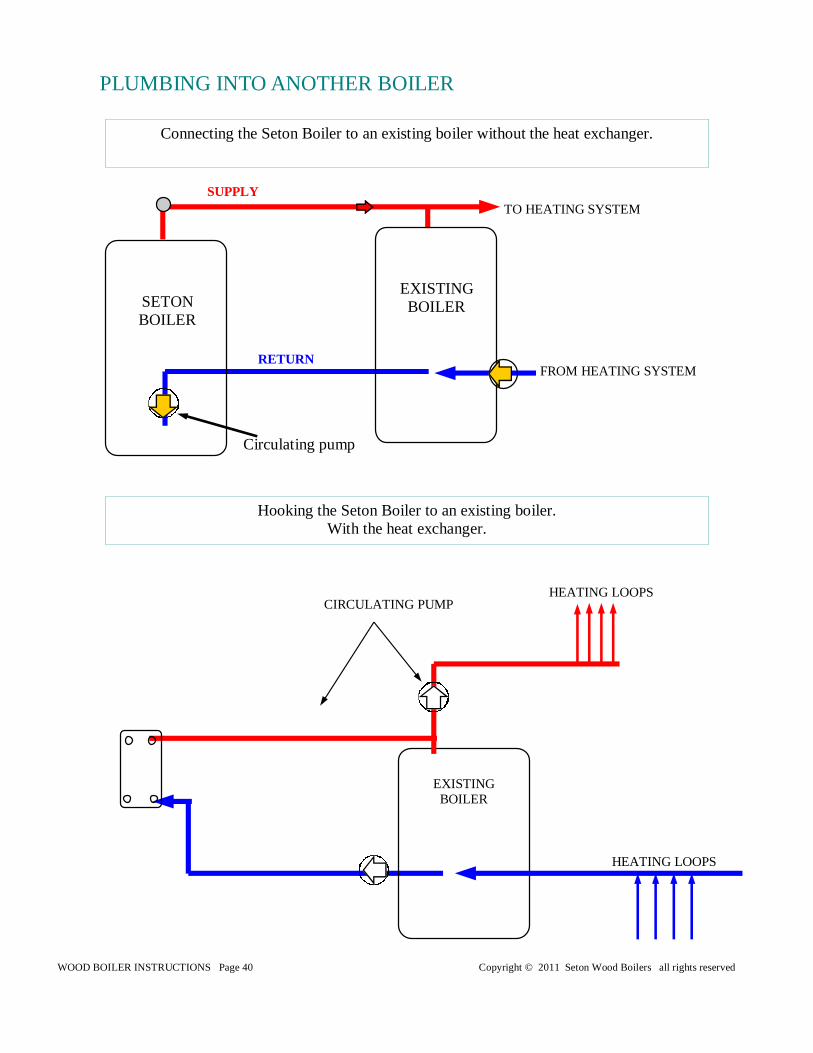
Hooking the Seton Boiler to an existing boiler. With the heat exchanger.
PLUMBING INTO ANOTHER BOILER
Connecting the Seton Boiler to an existing boiler without the heat exchanger.
Circulating pump
SETON BOILER
EXISTING BOILER
SUPPLY
RETURN
TO HEATING SYSTEM
FROM HEATING SYSTEM
WOOD BOILER INSTRUCTIONS Page 41 Copyright © 2011 Seton Wood Boilers all rights reserved
HEATING LOOPS
HEATING LOOPS
EXISTING BOILER
CHECK VALVE
CIRCULATING PUMP
Hooking the Seton Boiler to an existing boiler. With the heat exchanger.
PLUMBING INTO ANOTHER BOILER
WOOD BOILER INSTRUCTIONS Page 42 Copyright © 2011 Seton Wood Boilers all rights reserved
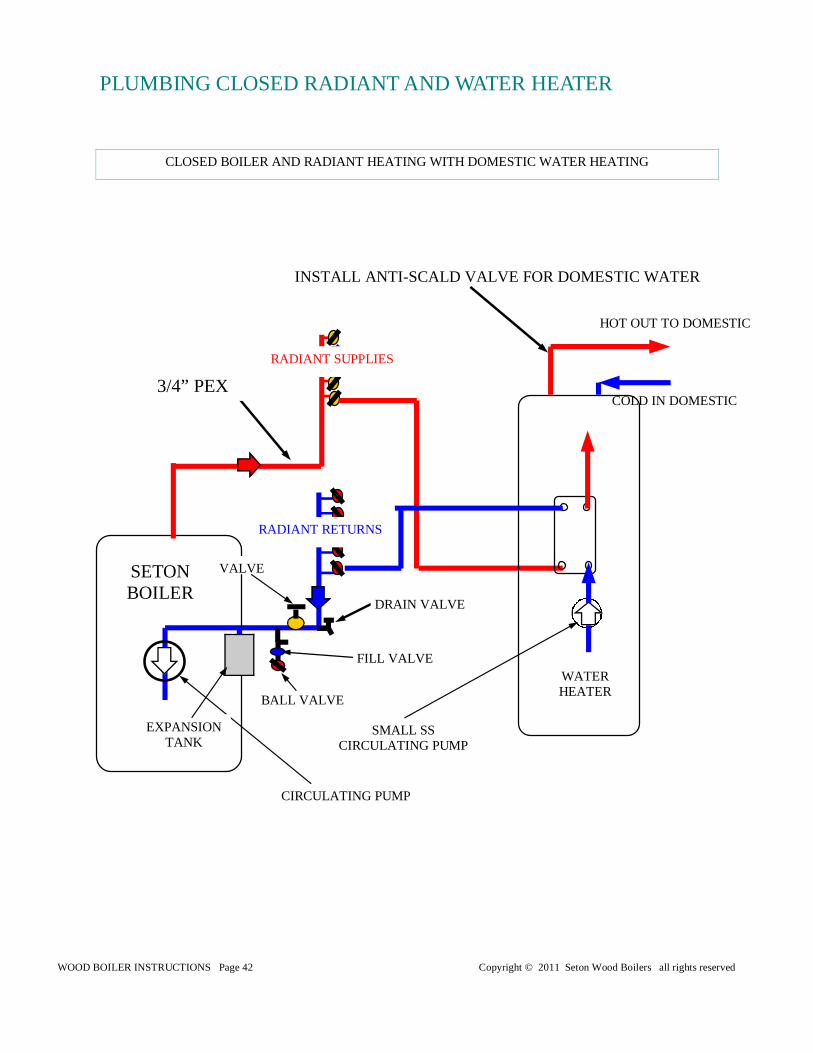
CIRCULATING PUMP
INSTALL ANTI-SCALD VALVE FOR DOMESTIC WATER
RADIANT SUPPLIES
RADIANT RETURNS
3/4” PEX
WATER HEATER
SMALL SS CIRCULATING PUMP
HOT OUT TO DOMESTIC
COLD IN DOMESTIC
SETON BOILER
VALVE
DRAIN VALVE
EXPANSION TANK
FILL VALVE
BALL VALVE
CLOSED BOILER AND RADIANT HEATING WITH DOMESTIC WATER HEATING
PLUMBING CLOSED RADIANT AND WATER HEATER
WOOD BOILER INSTRUCTIONS Page 43 Copyright © 2011 Seton Wood Boilers all rights reserved
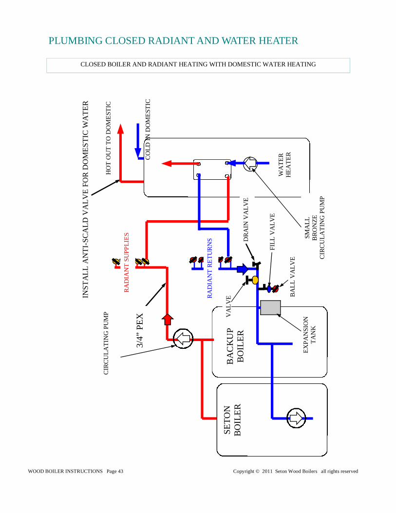
CLOSED BOILER AND RADIANT HEATING WITH DOMESTIC WATER HEATING
PLUMBING CLOSED RADIANT AND WATER HEATER
CIR
CU
LAT
ING
PU
MP
INS
TA
LL A
NT
I-S
CA
LD V
ALV
E F
OR
DO
ME
ST
IC W
AT
ER
RA
DIA
NT
SU
PP
LIE
S
RA
DIA
NT
RE
TU
RN
S
3/4”
PE
X
WA
TE
R
HE
AT
ER
SM
ALL
B
RO
NZ
E
CIR
CU
LAT
ING
PU
MP
HO
T O
UT
TO
DO
ME
ST
IC
CO
LD I
N D
OM
ES
TIC
BA
CK
UP
B
OIL
ER
VA
LVE
DR
AIN
VA
LVE
EX
PA
NS
ION
T
AN
K
FIL
L V
ALV
E
BA
LL
VA
LVE
SE
TO
N
BO
ILE
R
WOOD BOILER INSTRUCTIONS Page 44 Copyright © 2011 Seton Wood Boilers all rights reserved
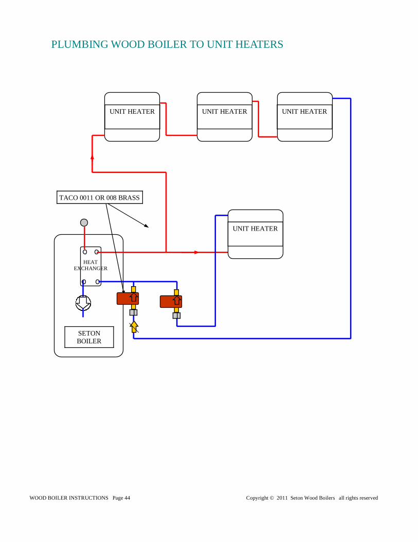
SETON BOILER
TACO 0011 OR 008 BRASS
UNIT HEATER UNIT HEATER UNIT HEATER
UNIT HEATER
PLUMBING WOOD BOILER TO UNIT HEATERS
HEAT EXCHANGER
WOOD BOILER INSTRUCTIONS Page 45 Copyright © 2011 Seton Wood Boilers all rights reserved
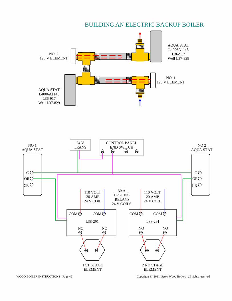
BUILDING AN ELECTRIC BACKUP BOILER
AQUA STAT L4006A1145
L36-917 Well L37-829
NO. 2 120 V ELEMENT
NO. 1 120 V ELEMENT
NO NO
110 VOLT 20 AMP
24 V COIL
110 VOLT 20 AMP
24 V COIL
CONTROL PANEL END SWITCH
CR
OR
C
30 A DPST NO RELAYS
24 V COILS
COM COM COM COM
NO NO
1 ST STAGE ELEMENT
2 ND STAGE ELEMENT
NO 1 AQUA STAT
24 V TRANS
CR
OR
C
NO 2 AQUA STAT
L38-291 L38-291
AQUA STAT L4006A1145
L36-917 Well L37-829
WOOD BOILER INSTRUCTIONS Page 46 Copyright © 2011 Seton Wood Boilers all rights reserved
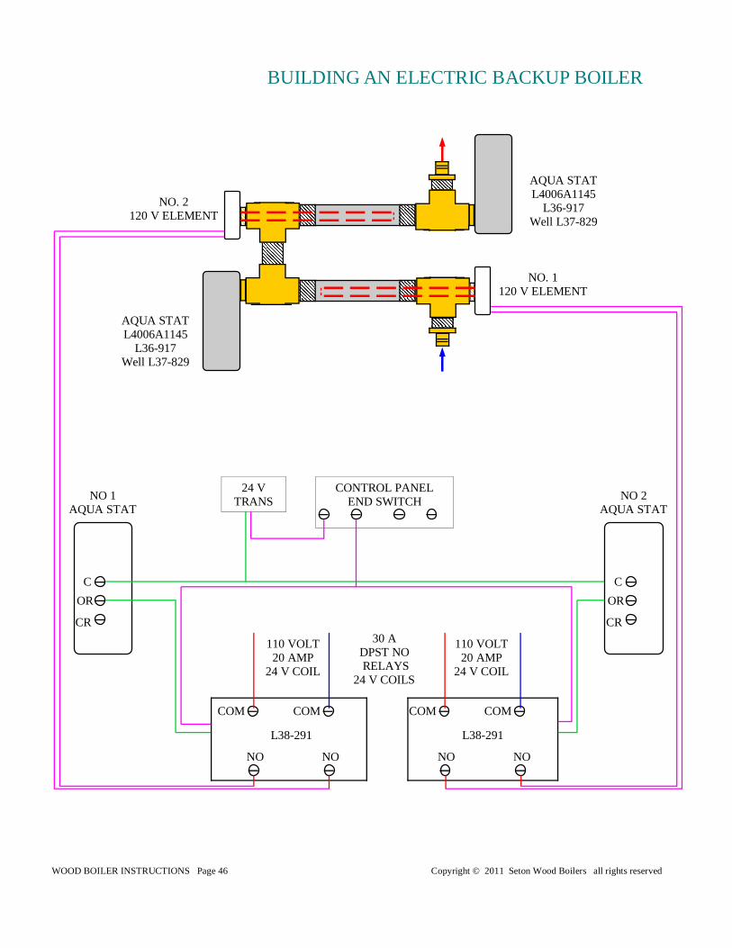
BUILDING AN ELECTRIC BACKUP BOILER
AQUA STAT L4006A1145
L36-917 Well L37-829
NO. 2 120 V ELEMENT
NO. 1 120 V ELEMENT
NO NO
110 VOLT 20 AMP
24 V COIL
110 VOLT 20 AMP
24 V COIL
CONTROL PANEL END SWITCH
CR
OR
C
30 A DPST NO RELAYS
24 V COILS
COM COM COM COM
NO NO
NO 1 AQUA STAT
24 V TRANS
CR
OR
C
NO 2 AQUA STAT
L38-291 L38-291
AQUA STAT L4006A1145
L36-917 Well L37-829
WOOD BOILER INSTRUCTIONS Page 47 Copyright © 2011 Seton Wood Boilers all rights reserved
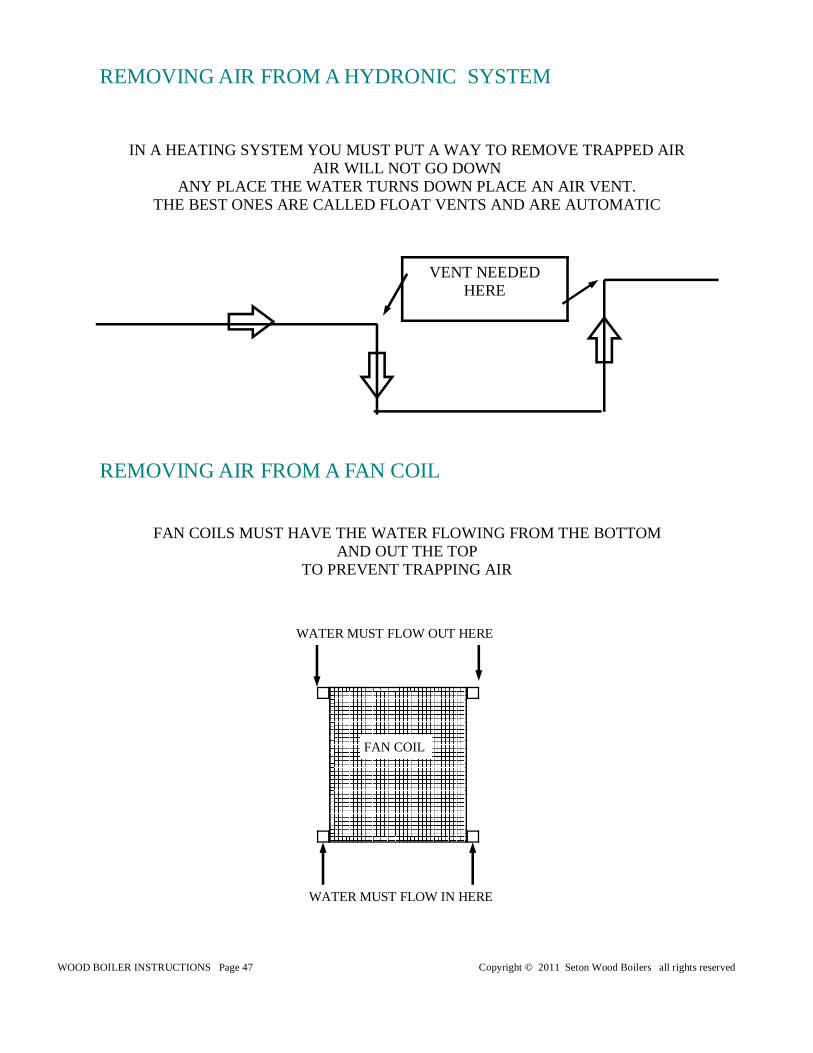
FAN COIL
IN A HEATING SYSTEM YOU MUST PUT A WAY TO REMOVE TRAPPED AIR AIR WILL NOT GO DOWN
ANY PLACE THE WATER TURNS DOWN PLACE AN AIR VENT. THE BEST ONES ARE CALLED FLOAT VENTS AND ARE AUTOMATIC
REMOVING AIR FROM A HYDRONIC SYSTEM
VENT NEEDED HERE
REMOVING AIR FROM A FAN COIL
FAN COILS MUST HAVE THE WATER FLOWING FROM THE BOTTOM AND OUT THE TOP
TO PREVENT TRAPPING AIR
WATER MUST FLOW OUT HERE
WATER MUST FLOW IN HERE
WOOD BOILER INSTRUCTIONS Page 48 Copyright © 2011 Seton Wood Boilers all rights reserved
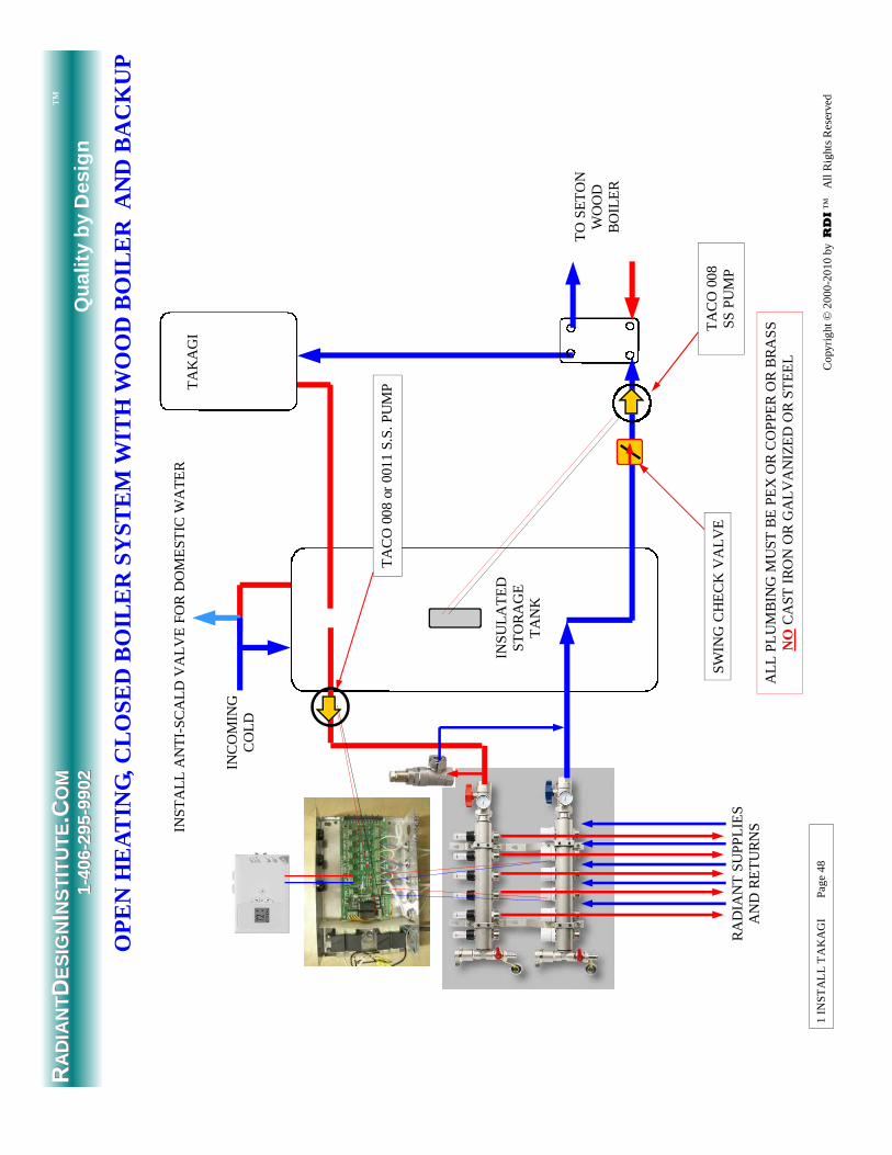
1 IN
ST
AL
L T
AK
AG
I
P
ag
e 4
8
RA
DIA
NT
SU
PP
LIE
S
AN
D R
ET
UR
NS
TO
SE
TO
N
WO
OD
B
OIL
ER
OP
EN
HE
AT
ING
, CLO
SE
D B
OIL
ER
SY
ST
EM
WIT
H W
OO
D B
OIL
ER
AN
D B
AC
KU
P
TA
KA
GI
ALL
PL
UM
BIN
G M
US
T B
E P
EX
OR
CO
PP
ER
OR
BR
AS
S
NO
CA
ST
IR
ON
OR
GA
LVA
NIZ
ED
OR
ST
EE
L
INS
ULA
TE
D
ST
OR
AG
E
TA
NK
TA
CO
008
S
S P
UM
P
SW
ING
CH
EC
K V
ALV
E
RRA
DIA
NT
AD
IAN
TDD
ES
IGN
ES
IGN
II NS
TIT
UT
EN
ST
ITU
TE
.C.CO
MO
M
11-- 4
0640
6-- 2
9529
5-- 9
902
99
02
Qu
alit
y b
y D
esig
n
™
Co
pyri
ght
© 2
00
0-2
01
0 b
y RDI ™
A
ll R
ight
s R
ese
rve
d
TA
CO
008
or
0011
S.S
. PU
MP
INS
TA
LL A
NT
I-S
CA
LD V
ALV
E F
OR
DO
ME
ST
IC W
AT
ER
INC
OM
ING
C
OLD
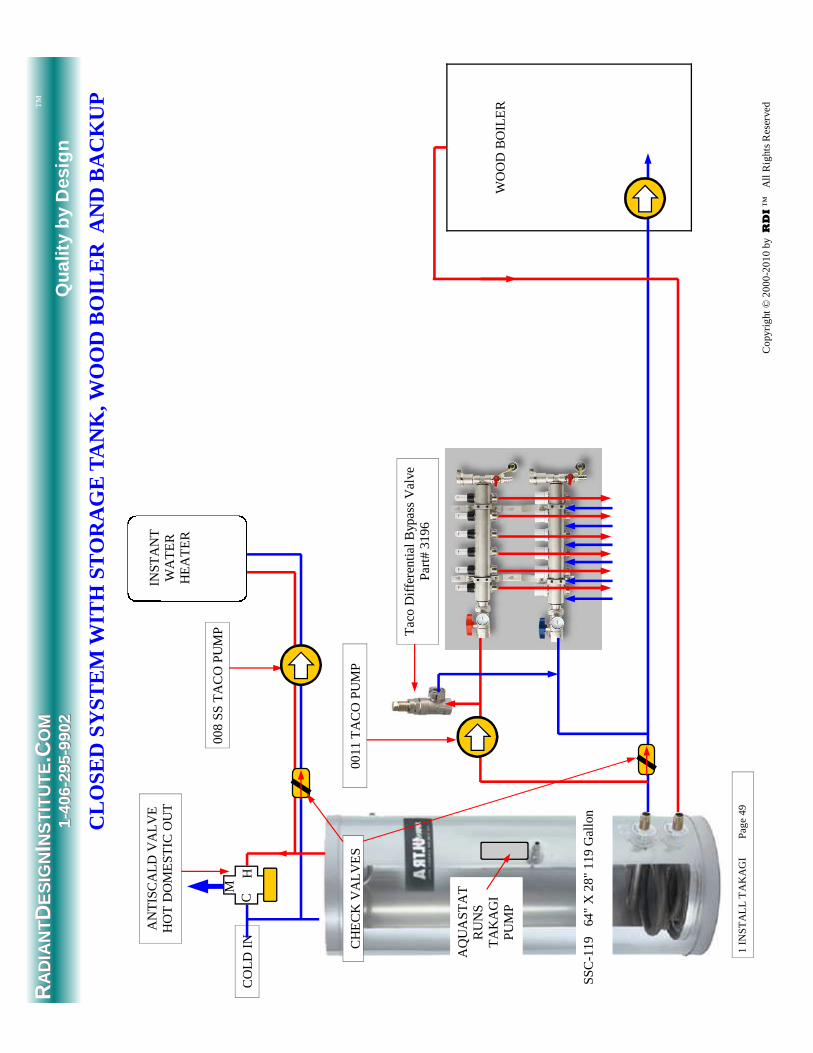
WOOD BOILER INSTRUCTIONS Page 49 Copyright © 2011 Seton Wood Boilers all rights reserved
1 IN
ST
AL
L T
AK
AG
I
P
ag
e 4
9
CLO
SE
D S
YS
TE
M W
ITH
ST
OR
AG
E T
AN
K, W
OO
D B
OIL
ER
AN
D B
AC
KU
P
RRA
DIA
NT
AD
IAN
TDD
ES
IGN
ES
IGN
II NS
TIT
UT
EN
ST
ITU
TE
.C.CO
MO
M
11-- 4
0640
6-- 2
9529
5-- 9
902
99
02
Qu
alit
y b
y D
esig
n
™
WO
OD
BO
ILE
R
AN
TIS
CA
LD V
ALV
E
HO
T D
OM
ES
TIC
OU
T
0011
TA
CO
PU
MP
INS
TA
NT
W
AT
ER
H
EA
TE
R
CO
LD I
N
008
SS
TA
CO
PU
MP
CH
EC
K V
ALV
ES
M
C
SS
C-1
19
64"
X 2
8" 1
19 G
allo
n
Ta
co D
iffer
entia
l Byp
ass
Va
lve
P
art
# 31
96
Co
pyri
ght
© 2
00
0-2
01
0 b
y RDI ™
A
ll R
ight
s R
ese
rve
d
H
AQ
UA
ST
AT
R
UN
S
TA
KA
GI
PU
MP
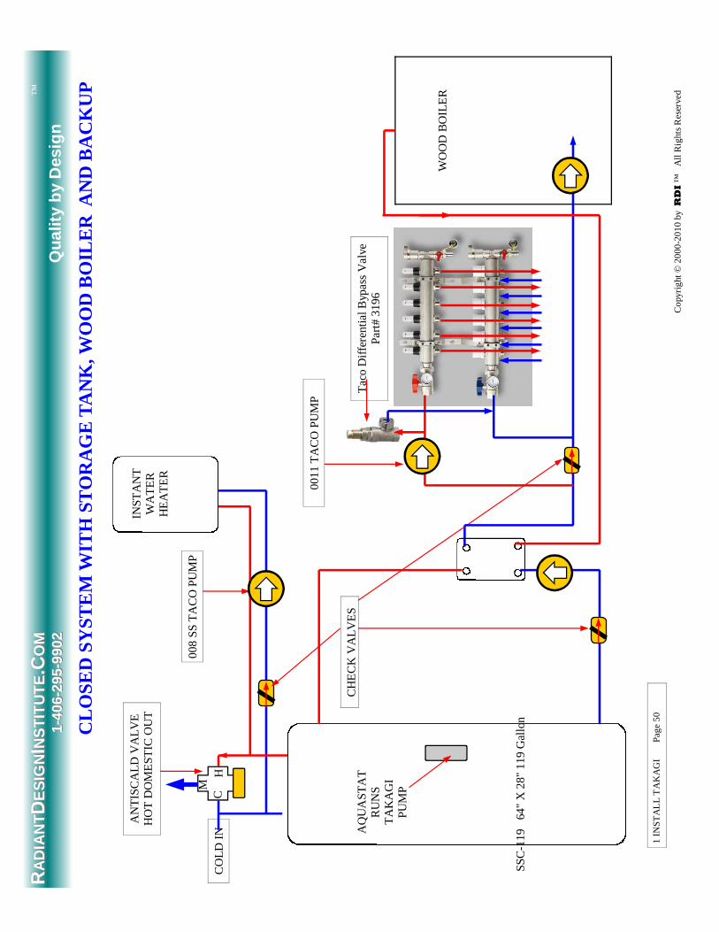
WOOD BOILER INSTRUCTIONS Page 50 Copyright © 2011 Seton Wood Boilers all rights reserved
1 IN
ST
AL
L T
AK
AG
I
P
ag
e 5
0
CLO
SE
D S
YS
TE
M W
ITH
ST
OR
AG
E T
AN
K, W
OO
D B
OIL
ER
AN
D B
AC
KU
P
RRA
DIA
NT
AD
IAN
TDD
ES
IGN
ES
IGN
II NS
TIT
UT
EN
ST
ITU
TE
.C.CO
MO
M
11-- 4
0640
6-- 2
9529
5-- 9
902
99
02
Qu
alit
y b
y D
esig
n
™
WO
OD
BO
ILE
R
AN
TIS
CA
LD V
ALV
E
HO
T D
OM
ES
TIC
OU
T
0011
TA
CO
PU
MP
INS
TA
NT
W
AT
ER
H
EA
TE
R
CO
LD I
N
008
SS
TA
CO
PU
MP
CH
EC
K V
ALV
ES
M
C
SS
C-1
19
64"
X 2
8" 1
19 G
allo
n
Ta
co D
iffer
entia
l Byp
ass
Va
lve
P
art
# 31
96
Co
pyri
ght
© 2
00
0-2
01
0 b
y RDI ™
A
ll R
ight
s R
ese
rve
d
H
AQ
UA
ST
AT
R
UN
S
TA
KA
GI
PU
MP
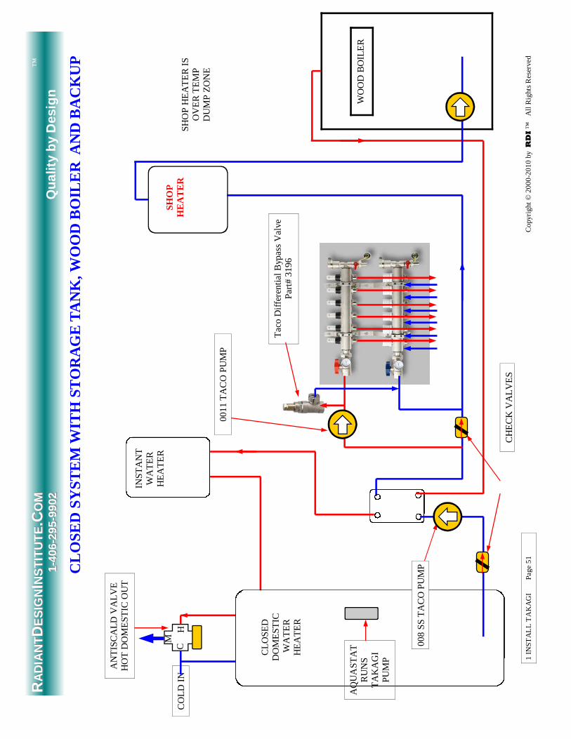
WOOD BOILER INSTRUCTIONS Page 51 Copyright © 2011 Seton Wood Boilers all rights reserved
1 IN
ST
AL
L T
AK
AG
I
P
ag
e 5
1
CLO
SE
D S
YS
TE
M W
ITH
ST
OR
AG
E T
AN
K, W
OO
D B
OIL
ER
AN
D B
AC
KU
P
RRA
DIA
NT
AD
IAN
TDD
ES
IGN
ES
IGN
II NS
TIT
UT
EN
ST
ITU
TE
.C.CO
MO
M
11-- 4
0640
6-- 2
9529
5-- 9
902
99
02
Qu
alit
y b
y D
esig
n
™
WO
OD
BO
ILE
R
AN
TIS
CA
LD V
ALV
E
HO
T D
OM
ES
TIC
OU
T
0011
TA
CO
PU
MP
INS
TA
NT
W
AT
ER
H
EA
TE
R
CO
LD I
N
CH
EC
K V
ALV
ES
M
C
CLO
SE
D
DO
ME
ST
IC
WA
TE
R
HE
AT
ER
Ta
co D
iffer
entia
l Byp
ass
Va
lve
P
art
# 31
96
Co
pyri
ght
© 2
00
0-2
01
0 b
y RDI ™
A
ll R
ight
s R
ese
rve
d
H
AQ
UA
ST
AT
R
UN
S
TA
KA
GI
PU
MP
SH
OP
H
EA
TE
R
SH
OP
HE
AT
ER
IS
O
VE
R T
EM
P
DU
MP
ZO
NE
008
SS
TA
CO
PU
MP
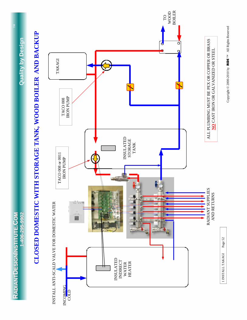
WOOD BOILER INSTRUCTIONS Page 52 Copyright © 2011 Seton Wood Boilers all rights reserved
1 IN
ST
AL
L T
AK
AG
I
P
ag
e 5
2
RA
DIA
NT
SU
PP
LIE
S
AN
D R
ET
UR
NS
TO
W
OO
D
BO
ILE
R
CLO
SE
D D
OM
ES
TIC
WIT
H S
TO
RA
GE
TA
NK
, WO
OD
BO
ILE
R A
ND
BA
CK
UP
INS
TA
LL A
NT
I-S
CA
LD V
ALV
E F
OR
DO
ME
ST
IC W
AT
ER
T
AC
O 0
08 o
r 00
11
IRO
N P
UM
P
INS
ULA
TE
D
IND
IRE
CT
W
AT
ER
H
EA
TE
R
TA
KA
GI
INC
OM
ING
C
OLD
ALL
PL
UM
BIN
G M
US
T B
E P
EX
OR
CO
PP
ER
OR
BR
AS
S
NO
CA
ST
IR
ON
OR
GA
LVA
NIZ
ED
OR
ST
EE
L
1 IN
ST
AL
L T
AK
AG
I
P
ag
e 5
2
INS
ULA
TE
D
ST
OR
AG
E
TA
NK
TA
CO
008
IR
ON
PU
MP
RRA
DIA
NT
AD
IAN
TDD
ES
IGN
ES
IGN
II NS
TIT
UT
EN
ST
ITU
TE
.C.CO
MO
M
11-- 4
0640
6-- 2
9529
5-- 9
902
99
02
Qu
alit
y b
y D
esig
n
™
Co
pyri
ght
© 2
00
0-2
01
0 b
y RDI ™
A
ll R
ight
s R
ese
rve
d
WOOD BOILER INSTRUCTIONS Page 53 Copyright © 2011 Seton Wood Boilers all rights reserved
TO
W
OO
D
BO
ILE
R
DO
ME
ST
IC O
UT
TA
KA
GI
B
OIL
ER
Ta
co D
iffer
ent
ial B
ypa
ss V
alv
e P
art
# 3
19
6
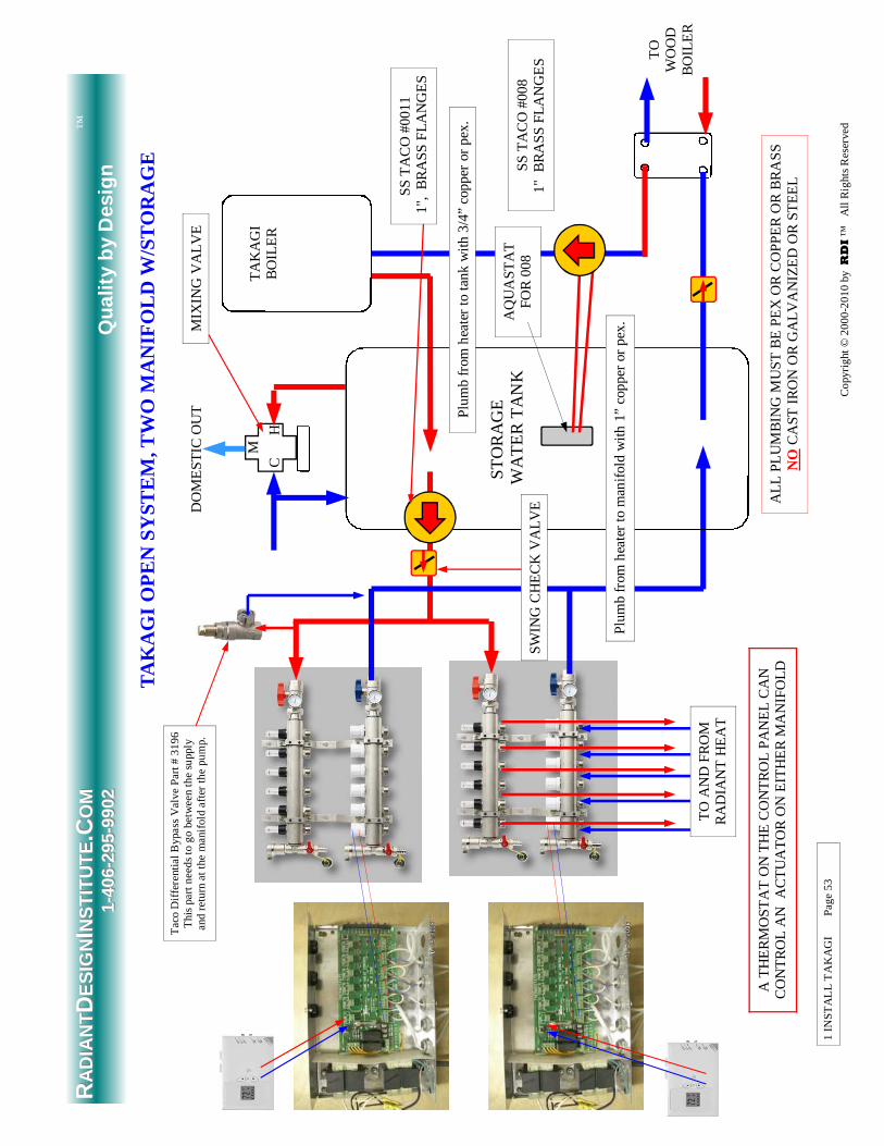
Thi
s pa
rt n
ee
ds
to g
o be
twe
en
the
supp
ly
and
re
turn
at
the
ma
nifo
ld a
fter
the
pum
p.
SS
TA
CO
#00
11
1",
BR
AS
S F
LAN
GE
S
TAK
AG
I OP
EN
SY
ST
EM
, TW
O M
AN
IFO
LD W
/ST
OR
AG
E
ST
OR
AG
E
WA
TE
R T
AN
K
C M
H
MIX
ING
VA
LVE
TO
AN
D F
RO
M
RA
DIA
NT
HE
AT
Plu
mb
from
hea
ter
to t
ank
with
3/4
” co
pper
or
pex.
SS
TA
CO
#00
8 1"
B
RA
SS
FLA
NG
ES
ALL
PL
UM
BIN
G M
US
T B
E P
EX
OR
CO
PP
ER
OR
BR
AS
S
NO
CA
ST
IR
ON
OR
GA
LVA
NIZ
ED
OR
ST
EE
L
AQ
UA
ST
AT
F
OR
008
Plu
mb
from
hea
ter
to m
anifo
ld w
ith 1
” co
pper
or
pex.
A T
HE
RM
OS
TA
T O
N T
HE
CO
NT
RO
L P
AN
EL
CA
N
CO
NT
RO
L A
N
AC
TU
AT
OR
ON
EIT
HE
R M
AN
IFO
LD
1 IN
ST
AL
L T
AK
AG
I
P
ag
e 5
3
SW
ING
CH
EC
K V
ALV
E
RRA
DIA
NT
AD
IAN
TDD
ES
IGN
ES
IGN
II NS
TIT
UT
EN
ST
ITU
TE
.C.CO
MO
M
11-- 4
0640
6-- 2
9529
5-- 9
902
99
02
Qu
alit
y b
y D
esig
n
™
Co
pyri
ght
© 2
00
0-2
01
0 b
y RDI ™
A
ll R
ight
s R
ese
rve
d
WOOD BOILER INSTRUCTIONS Page 54 Copyright © 2011 Seton Wood Boilers all rights reserved
What's the Negative Air Problem? Negative indoor pressure results when more air is leaving your home than is coming in, creat-ing a partial vacuum. In winter, the heated indoor air rises up through the structure and escapes from upper level leaks. At the same time, we force air out of the house with kitchen and bath fans, clothes dryers, furnaces, fireplaces and water heaters, all of which contribute to the nega-tive pressure problem, which is a lack of "make-up air." Sometimes this can lead to annoying situations, such as a fireplace or stove that leaks smoke (or that won't draw at all). At other times, a more dangerous situation can result, such as a flow reversal in a furnace chimney that spills carbon monoxide into the house. Many building scien-tists now advise make-up air systems for all new homes, and it is general practice now to re-quire make-up air in new European houses. Many people ask if ventilating in cold weather isn't an energy wasting practice. The fact is, most heated homes will leak some air due to pressure differences and the natural stack effect of the house. (Stack Effect means your whole house works like a chimney, with heated air rising up the stairways, for example.) If you crack open a window, you will usually feel air coming in to the house rather than blowing out. Without planned ventilation, this negative pressure will suck air in at uncontrolled points. One way to address this negative pressurization is to ventilate with Condar's ASV-90 Air Supply Ventilator. When you control ventilation, you determine when and where air enters your home, getting the maximum benefit from the least amount of air. While no one product can deal with every house pressure problem, there is an easy test you can perform to check whether the ASV-90 will work for you. Once you've identified a pressure problem, such as a fireplace or stove that won't draw well, try cracking open a window in the room. If that helps the draw, this product will do the job when properly positioned and installed.
http://www.condar.com/
Also a good place for stack thermometers.
NEGATIVE AIR PROBLEMS
WOOD BOILER INSTRUCTIONS Page 55 Copyright © 2011 Seton Wood Boilers all rights reserved
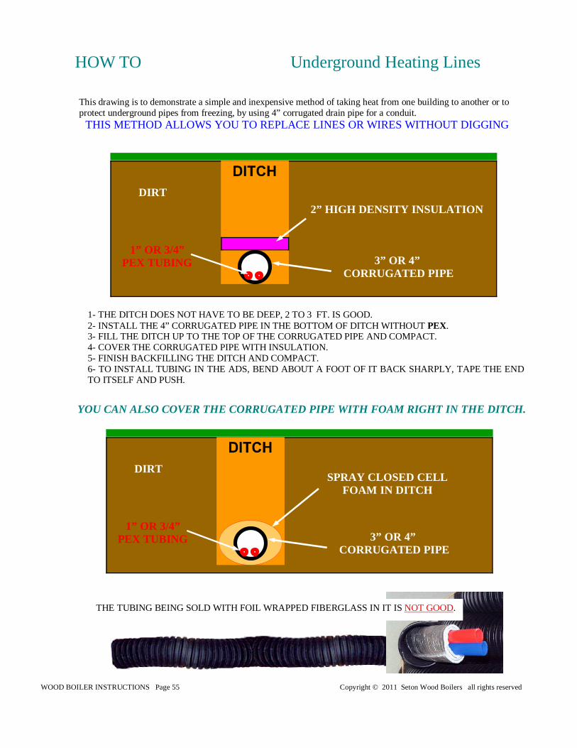
HOW TO Underground Heating Lines
This drawing is to demonstrate a simple and inexpensive method of taking heat from one building to another or to protect underground pipes from freezing, by using 4” corrugated drain pipe for a conduit.
THIS METHOD ALLOWS YOU TO REPLACE LINES OR WIRES WITHOUT DIGGING
1- THE DITCH DOES NOT HAVE TO BE DEEP, 2 TO 3 FT. IS GOOD. 2- INSTALL THE 4” CORRUGATED PIPE IN THE BOTTOM OF DITCH WITHOUT PEX. 3- FILL THE DITCH UP TO THE TOP OF THE CORRUGATED PIPE AND COMPACT. 4- COVER THE CORRUGATED PIPE WITH INSULATION. 5- FINISH BACKFILLING THE DITCH AND COMPACT. 6- TO INSTALL TUBING IN THE ADS, BEND ABOUT A FOOT OF IT BACK SHARPLY, TAPE THE END TO ITSELF AND PUSH.
YOU CAN ALSO COVER THE CORRUGATED PIPE WITH FOAM RIGHT IN THE DITCH.
DIRT
1” OR 3/4” PEX TUBING
SPRAY CLOSED CELL FOAM IN DITCH
3” OR 4” CORRUGATED PIPE
DIRT
2” HIGH DENSITY INSULATION
3” OR 4” CORRUGATED PIPE
1” OR 3/4” PEX TUBING
THE TUBING BEING SOLD WITH FOIL WRAPPED FIBERGLASS IN IT IS NOT GOOD.
WOOD BOILER INSTRUCTIONS Page 56 Copyright © 2011 Seton Wood Boilers all rights reserved
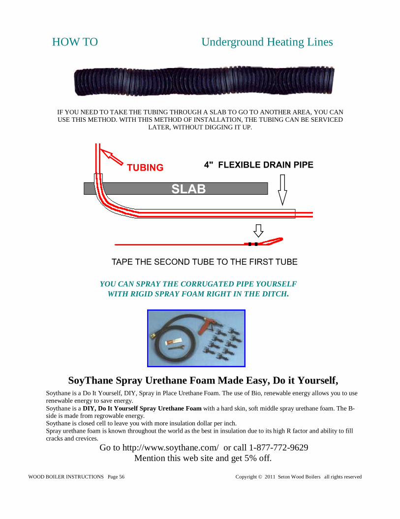
IF YOU NEED TO TAKE THE TUBING THROUGH A SLAB TO GO TO ANOTHER AREA, YOU CAN USE THIS METHOD. WITH THIS METHOD OF INSTALLATION, THE TUBING CAN BE SERVICED
LATER, WITHOUT DIGGING IT UP.
HOW TO Underground Heating Lines
YOU CAN SPRAY THE CORRUGATED PIPE YOURSELF WITH RIGID SPRAY FOAM RIGHT IN THE DITCH.
SoyThane Spray Urethane Foam Made Easy, Do it Yourself, Soythane is a Do It Yourself, DIY, Spray in Place Urethane Foam. The use of Bio, renewable energy allows you to use renewable energy to save energy. Soythane is a DIY, Do It Yourself Spray Urethane Foam with a hard skin, soft middle spray urethane foam. The B-side is made from regrowable energy. Soythane is closed cell to leave you with more insulation dollar per inch. Spray urethane foam is known throughout the world as the best in insulation due to its high R factor and ability to fill cracks and crevices.
Go to http://www.soythane.com/ or call 1-877-772-9629 Mention this web site and get 5% off.
WOOD BOILER INSTRUCTIONS Page 57 Copyright © 2011 Seton Wood Boilers all rights reserved
WARRANTEE
1110 YEAR WARRANTEE0 YEAR WARRANTEE0 YEAR WARRANTEE Seton Manufacturing Inc. warrantees the Seton boiler that it manufactures for twelve years un-der the following conditions. Any time within twenty four years if the refractory or pressure vessel, fails we will replace that part at the cost of that part minus 1/12 the cost of that part times the number of years you have owned the boiler plus shipping costs. This does not cover parts we do not manufacture, such as but not limited to the S.S. heat ex-changer, draft motor, gauges, aquastats, pumps, pressure reducing valves and pop offs. Failure to follow the instructions furnished with the Seton boiler will void the warrantee.
Some of the things that are not covered are:
• Burning fuels that are not approved, such as but not limited to, tires, pressure treated wood,
railroad ties, garbage, plastics, oil, any liquid, paper products and cardboard except paper for starting a fire.
• Damage from holding or forcing the draft open or running the boiler with the feed door
open . • Using a chimney that is not approved. • Using a chimney that will not maintain a minimum of .06 inches water column. • Firing the boiler without water in the pressure vessel. • Operating the boiler in a constant condensing state because of an inadequate chimney or
low boiler water temperature settings • Any damage created by electrical outages or loss or electrical power.
WOOD BOILER INSTRUCTIONS Page 58 Copyright © 2011 Seton Wood Boilers all rights reserved
Step 1 Flush system with clean water. Add Prep Solution 102™ per directions.
Step 2 Drain and flush thoroughly.
Step 3 Refill and add required amount of Treatment Solution 101™ per directions. System is ready to use.
Step 4 Test chemical level biannually, adding as necessary to always maintain a proper chemical level.
Step 5 Add Biological Solution per instructions every third season or as necessary to control biological growth.
The Successful Plan - Pressurized "Closed" Outdoor Wood Boiler
BOILER MAINTENANCE
Step 1 Clean and passivate system with required amount of Prep Solution 102™ per directions for new boiler.
Step 2 Drain and flush thoroughly.
Step 3 Refill and add required amount of Treatment Solution 101™. System is ready for use.
Step 4 Test chemical level each month and add accordingly to always maintain a proper chemical level.
Step 5 Prior to the end of the heating season and draining add Lay -Up Solution 103™ per directions.
Step 6 Drain and flush thoroughly.
Step 7 Refill and add required amount of Treatment Solution 101™. Add required amount of Biological Solution
Step 8 Repeat Steps 4 - 7.
** If necessary use Scale-Out Solution 115™ per directions at Step 5 in place of Lay-Up Solution 103™. (FLUSH THOROUGHLY) Following Scale-Out repeat steps beginning with Step 1.
New Non-Pressurized "Open" Outdoor Wood Boiler
Step 1 Address and remove existing scale deposits if any exist following directions and dosages for Scale-Out Solution . (FLUSH THOROUGHLY)
Step 2 Clean and passivate system with required amount of Prep Solution 102™ per directions for an existing boiler.
Step 3 Follow Steps 2-8 for a new outdoor wood boiler.
Existing Non-Pressurized "Open" Outdoor Wood Boiler
There is lots of “stuff” in your water, especially well water (municipalities treat water to some varying degree in relation to our purposes, therefore problems are lessened with "city" water supplies), all which pose problems for your system. Examples: calcium (lime), iron, oxygen. That is why you treat the water. A "closed" system is no exception. Without proper treatment of the water in your system you are allowing corrosion and scale deposition to destroy the metals and destroy the efficiency and longevity of your system. Scaling issues are decreased considerably but oxygen remains a threat to your system. "Closed" systems are by no means air tight. Your outdoor wood boiler has basic treatment requirements in regard to properly and effectively using water as a medium for heat exchange as its larger industrial cousins. Same kinds of problems, same kind of medicine. Regardless of the metals used to construct your particular brand boiler they ALL need treatment EQUALLY. Water treatment is an ongoing preventative maintenance process, NOT a one time “dump a jug in and I’m done” process. You change the oil in your car periodically even if the dipstick says full don’t you?! Water treatment maintenance is lessened for a "closed" system compared to an "open".
WOOD BOILER INSTRUCTIONS Page 59 Copyright © 2011 Seton Wood Boilers all rights reserved
Hot Water Boiler Preventive Maintenance The following only refers to boiler systems in general and is for educational purposes only. Refer to your owners' manual or consult with your local boiler technician for proper maintenance procedures and operation of your heating system. The procedures described here should only perform by a qualified technician. Serious injury or death could result if improperly handled. Boiler Pressure: Look for a temperature Pressure Gauge on the front of your boiler. Normally just above the burners or on side manifold. For most residential and small commercial systems this pressure should be 12-15 pounds. Read the gauge when the boiler is cold and the circulating pump is off. This will show the static water pressure of your boiler set by the water feed regulator. If the pressure is too high the regu-lator may be set too high or leaking through the regulator. If the feed regulator bypasses even a small amount of water from scale or sediment trapped in the seat the pressure on the system will creep up to the pressure relief set point and blow off water. Expansion tank: As water is heated it will expand and occupy a larger volume. The expansion tank should allow sufficient volume to allow for expansion. There are two types of expansion tanks. A Dia-phragm Tank, which uses a bladder, filled with compressed air, or a steel holding tank, which traps air in the top, half. The diaphragm tank is charged with air to the same operating pressure of the boiler set by the feed regulator. Do not release or add air to the diaphragm tank is connected the boiler system or it will not function properly. Tap on the tank and it should sound hollow through out. If the bladder has leaked the tank will completely fill with water. If the tank is not properly charged with air, the diaphragm tank will fill 1/2 way with water. For the steel holding tanks there should be a sight glass on the front of the tank to indicate the water level in the tank. The tank should be about half full. If the tank is filled near the top or completely filled the water will have to be drained off. Turn the boiler off and attach a hose to the drain valve of the expansion tank. Close the valve that connects the expansion tank to the boiler and open the drain valve. Drain the tank until it is empty. Then close the drain valve and open the valve to the boiler system. The expansion tank should filled to the half way mark or less and trap air in the top of the tank. If the tank fills again after a few days then there is an air leak in the tank. Pressure Relief Valve: Every boiler has at least one pressure relief valve. If the pressure climbs too high on your boiler it will open and blow off the excessive pressure and close again when the pressure falls be-low the setpoint. There should be a tag on the valve to tell you at what pressure it will open. Most residen-tial boilers will be set to 30#. If your boiler is operating close to this setpoint the pressure relief valve will leak slowly. The cause of the high boiler pressure needs to found. At least once a year this valve should be open to blow off water and make sure it has not plugged up with sediment and scale. Check the boiler pressure before you begin, if it is close to the setpoint the relief valve will not close right away. The outlet of the relief valve should be piped to 6" above the floor and to a place where it will not cause water dam-age if opened. This makes annual blow down on the relief valve easy. It can be piped directly to a floor drain, but the outlet should be open so any leakage can be detected. If the unit is not piped to a drain use a bucket to catch the water if needed. Make sure you know where the boiler feed water shut off is, just in case. With the boiler off and cold, lift the manual lever and blow off some water for a few seconds and let the lever snap back. There should be a good gush that comes out and be fairly clear water. If the valve has small leaks after wards, just open it again and let some more water out, sediment can become trapped in the seat causing minor leakage. If the valve will not close at all shut the boiler water feed off and remove and replace the relief valve. If no water comes out, then the valve is plugged or there is no water in the boiler. In either case do not use the boiler until the problem is identified and repaired.
BOILER MAINTENANCE
WOOD BOILER INSTRUCTIONS Page 60 Copyright © 2011 Seton Wood Boilers all rights reserved
BOILER MAINTENANCE
Cir culating Pump: Some of the older style boiler pumps require lubrication for the motor and the pump. The motor normally requires a few drops and the pump bearing should have and oil port. This needs to be filled to keep the oil wicks wet. Refer to the manufacturer instructions for lubrication procedure for you pump. There maybe more than one pump on you system. Some of the smaller cartridge style pumps do not require any maintenance. The volume of water circulated by the pump is very important to the boiler operation. Too little water will boil inside the heating coil and plug it with scale. This will sound like a crackling sound inside the boiler when the burner is operating. A single pres-sure gauge piped across the pump inlet and outlet is the best way to monitor pump performance. As the pressure dif-ference increases across the pump the lower the volume. The lower the pressure differences the higher the volume. Another way to check water flow is by temperature. When the burner is operating check the temperature rise through the boiler. Most are designed for a 10%F TD with nominal water flow. If the TD is higher 25%F or more the water flow is too low and can start to boil off in the heating coil. Temperature Setpoint: There could be up 4 temperature controller on a hot water boiler system. Room Thermostat, Boiler Water Temperature Control, Circulation pump temperature control, and the safety high limit control. Operating set point is normally an external control to the boiler. It controls the temperature of the circulating water. This can be a fixed setpoint set around 160°F to 180°F. Outdoor reset controls are not recommended. Circulation thermostats are used to start and stop the circulation pump and can be combined in the same control as the high limit. Normally the circ pump should be set around 100°F. On atmospheric boiler with draft hoods after the burner shuts down the continued draft starts to cool the water .Air from inside the boiler room is cooler then the water temperature in the boiler system. By shutting down the boiler circuit pump after the water cools helps to reduce this heat loss. High limit control is a safety limit switch that will shut the burner off if the water temperature gets too high. Check with the boiler manufacturer for the proper set point for your system. These are normally around 200°F but can be higher or lower. I have often found these being used as the operating control for the boiler because they are shipped with the boiler and the installer does not add the external operating control leaving the boiler without a safety high limit control. Coil Cleaning: Atmospheric boilers are used extensively in residential and small commercial applications for space heating, potable hot water and for pool and spas. The coils on these units plug up externally from the flue gas passing between the tubes. This reduces heat transfer and causes flue gas to spill out the front of the boiler. Every few years the top needs to be removed and the coil needs to be cleaned. If you notice staining on the face of the boiler or can feel hot flue gas spilling out the front of the boiler then the tubes is likely starting to plug up.
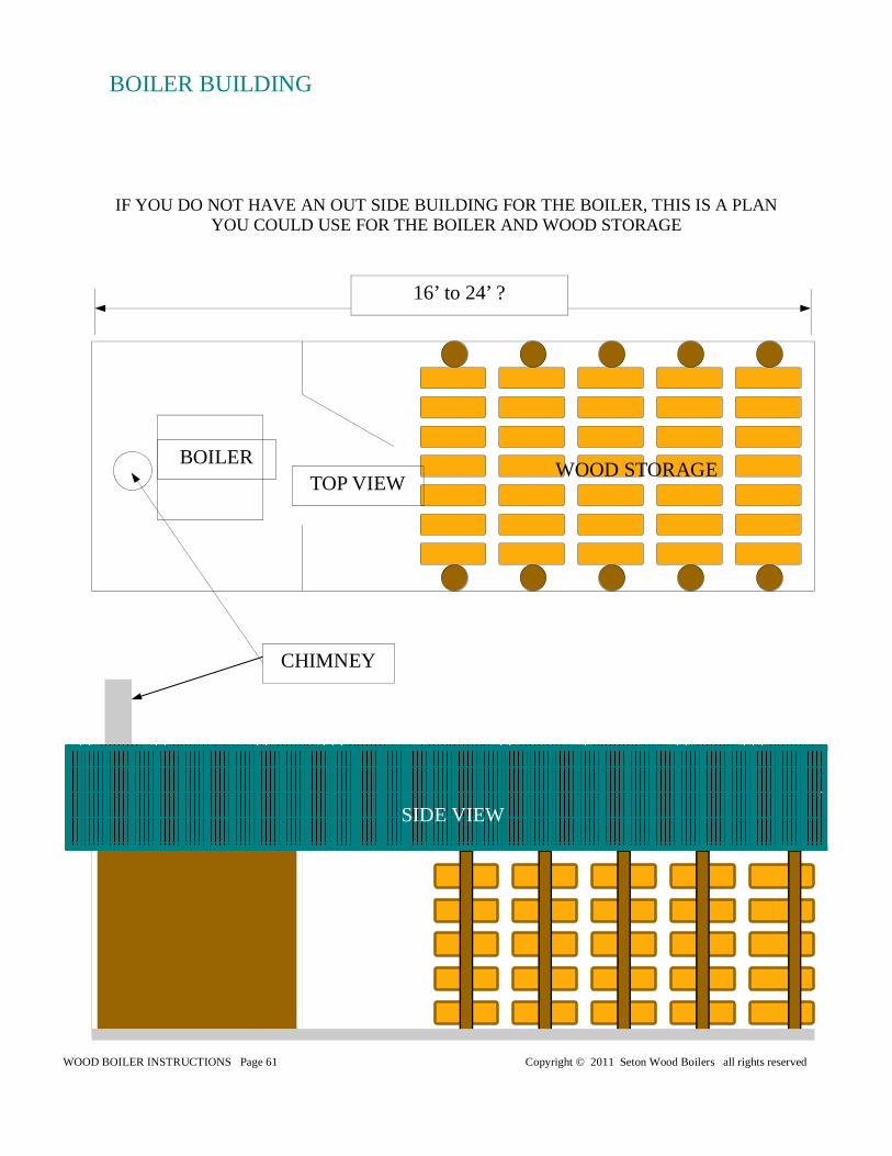
WOOD BOILER INSTRUCTIONS Page 61 Copyright © 2011 Seton Wood Boilers all rights reserved
IF YOU DO NOT HAVE AN OUT SIDE BUILDING FOR THE BOILER, THIS IS A PLAN YOU COULD USE FOR THE BOILER AND WOOD STORAGE
SIDE VIEW
TOP VIEW BOILER
CHIMNEY
16’ to 24’ ?
WOOD STORAGE
BOILER BUILDING
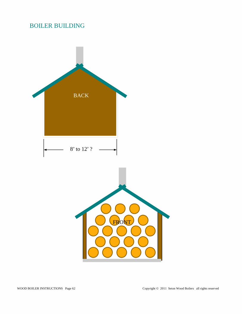
WOOD BOILER INSTRUCTIONS Page 62 Copyright © 2011 Seton Wood Boilers all rights reserved
BACK
FRONT
8’ to 12’ ?
BOILER BUILDING
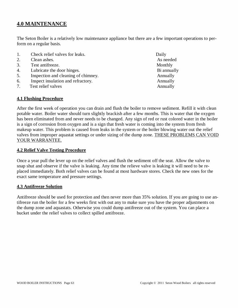
WOOD BOILER INSTRUCTIONS Page 63 Copyright © 2011 Seton Wood Boilers all rights reserved
4.0 MAINTENANCE The Seton Boiler is a relatively low maintenance appliance but there are a few important operations to per-form on a regular basis. 1. Check relief valves for leaks. Daily 2. Clean ashes. As needed 3. Test antifreeze. Monthly 4. Lubricate the door hinges. Bi annually 5. Inspection and cleaning of chimney. Annually 6. Inspect insulation and refractory. Annually 7. Test relief valves Annually
4.1 Flushing Procedure After the first week of operation you can drain and flush the boiler to remove sediment. Refill it with clean potable water. Boiler water should turn slightly brackish after a few months. This is water that the oxygen has been eliminated from and never needs to be changed. Any sign of red or rust colored water in the boiler is a sign of corrosion from oxygen and is a sign that fresh water is coming into the system from fresh makeup water. This problem is caused from leaks in the system or the boiler blowing water out the relief valves from improper aquastat settings or under sizing of the dump zone. THESE PROBLEMS CAN VOID YOUR WARRANTEE. 4.2 Relief Valve Testing Procedure Once a year pull the lever up on the relief valves and flush the sediment off the seat. Allow the valve to snap shut and observe if the valve is leaking. Any time the relieve valve is leaking it will need to be re-placed immediately. Both relief valves can be found at most hardware stores. Check the new ones for the exact same temperature and pressure settings. 4.3 Antifreeze Solution Antifreeze should be used for protection and then never more than 35% solution. If you are going to use an-tifreeze run the boiler for a few weeks first with out any to make sure you have the proper adjustments on the dump zone and aquastats. Otherwise you could dump antifreeze out of the system. You can place a bucket under the relief valves to collect spilled antifreeze.
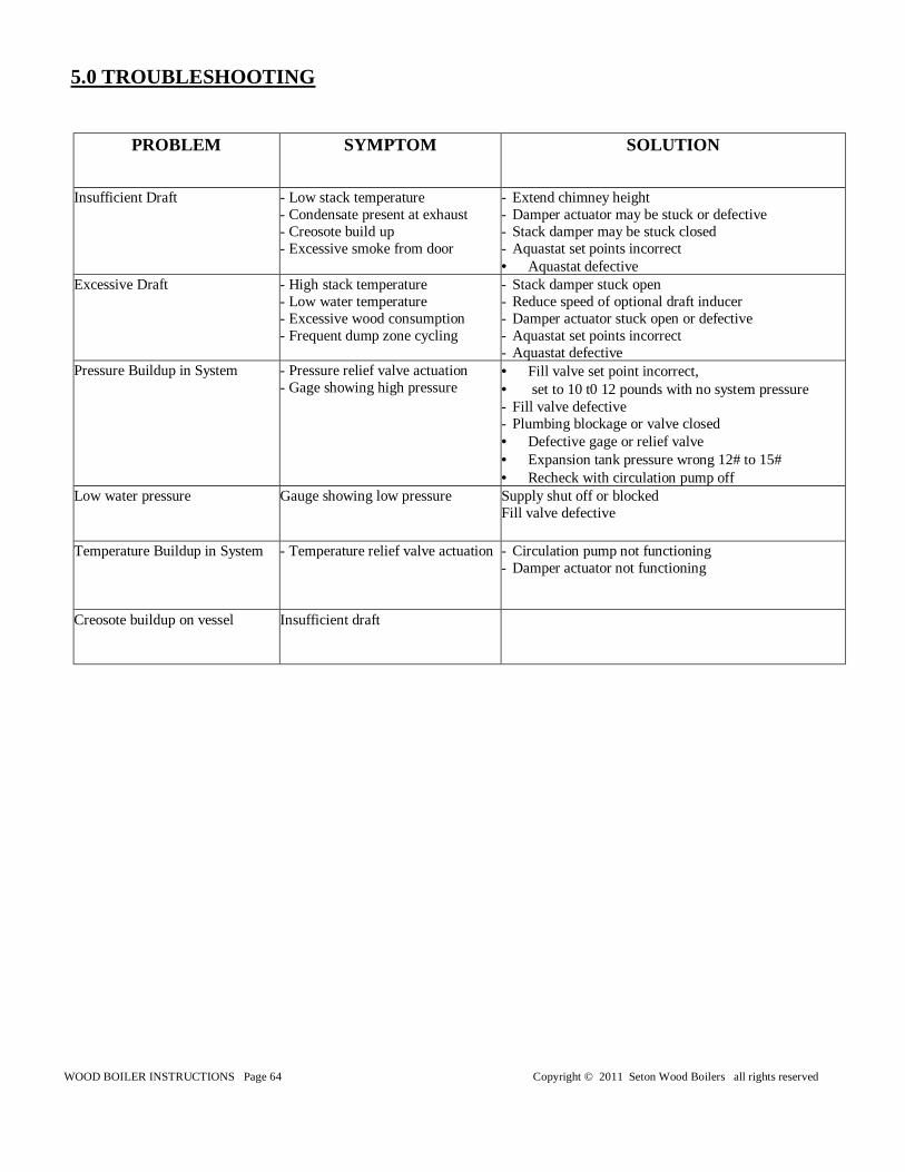
WOOD BOILER INSTRUCTIONS Page 64 Copyright © 2011 Seton Wood Boilers all rights reserved
5.0 TROUBLESHOOTING
PROBLEM SYMPTOM SOLUTION
Insufficient Draft - Low stack temperature - Condensate present at exhaust - Creosote build up - Excessive smoke from door
- Extend chimney height - Damper actuator may be stuck or defective - Stack damper may be stuck closed - Aquastat set points incorrect • Aquastat defective
Excessive Draft - High stack temperature - Low water temperature - Excessive wood consumption - Frequent dump zone cycling
- Stack damper stuck open - Reduce speed of optional draft inducer - Damper actuator stuck open or defective - Aquastat set points incorrect - Aquastat defective
Pressure Buildup in System - Pressure relief valve actuation - Gage showing high pressure
• Fill valve set point incorrect, • set to 10 t0 12 pounds with no system pressure - Fill valve defective - Plumbing blockage or valve closed • Defective gage or relief valve • Expansion tank pressure wrong 12# to 15# • Recheck with circulation pump off
Low water pressure Gauge showing low pressure Supply shut off or blocked Fill valve defective
Temperature Buildup in System - Temperature relief valve actuation - Circulation pump not functioning - Damper actuator not functioning
Creosote buildup on vessel Insufficient draft


![Caliper Operation Instructions[1]](https://img.pdfslide.net/doc/110x75/577cc5701a28aba7119c6424/caliper-operation-instructions1.jpg)