Embed Size (px)
Citation preview

1645 Lemonwood Dr. Santa Paula, CA, 93060 USA
Toll Free (888) 977-8225 Tel: (805) 933-9970 autostacker.com
Autostacker™ Parking Lift
Installation and Operation Manual Manual P/N 5900002 — Manual Revision D1 — October 2019
Models:
• PL-6SR
• PL-6SRX
U.S. Design Patent No. D814,736
Autostacker is designed and engineered by BendPak Inc. in Southern California, USA. Made in China.
DANGER ؍Read the entire contents of this Manual before using this product. Failure to follow the instructions and safety precautions in this manual can result in serious injury or death. Make sure all other operators also read this manual. Keep the manual near the product for future reference. By proceeding with setup and operation, you agree that you fully understand the contents of this manual.

Manual. Autostacker Parking Lift, Installation and Operation Manual, Manual P/N 5900002, Manual Revision D1, Released October 2019.
Copyright. Copyright © 2019 by BendPak Inc. All rights reserved. You may make copies of this document if you agree that: you will give full attribution to BendPak Inc., you will not make changes to the content, you do not gain any rights to this content, and you will not use the copies for commercial purposes.
Trademarks. BendPak and the BendPak logo are registered trademarks of BendPak Inc. Autostacker is a trademark of BendPak Inc. All other company, product, and service names are used for identification only. All trademarks and registered trademarks mentioned in this manual are the property of their respective owners.
Limitations. Every effort has been made to ensure complete and accurate instructions are included in this manual. However, product updates, revisions, and/or changes may have occurred since this manual was published. BendPak reserves the right to change any information in this manual without incurring any obligation for equipment previously or subsequently sold. BendPak is not responsible for typographical errors in this manual. You can always find the latest version of the manual for your product on the Autostacker website.
Warranty. The Autostacker warranty is more than a commitment to you: it is also a commitment to the value of your new product. For full warranty details, contact your nearest Autostacker dealer or visit autostacker.com/support/warranty.
Safety. Your product was designed and manufactured with safety in mind. Your safety also depends on proper training and thoughtful operation. Do not set up, operate, maintain, or repair the unit without reading and understanding this manual and the labels on the unit; do not use this product unless you can do so safely!
Owner Responsibility. In order to ensure operator safety and maintain your product properly, it is the responsibility of the product owner to read and follow these instructions: • Follow all setup, operation, and maintenance instructions. • Make sure product setup conforms to all applicable local, state, and federal codes, rules, and regulations,
such as state and federal OSHA regulations and electrical codes. • Read and follow all safety instructions. Keep them readily available for operators. • Make sure all operators are properly trained, know how to safely operate the unit, and are properly supervised. • Do not operate the product until you are certain that all parts are in place and operating correctly. • Carefully inspect the product on a regular basis and perform all maintenance as required. • Service and maintain the unit only with approved replacement parts. • Keep all instructions permanently with the product and make sure all labels are clean and visible. • Only use this product if it can be used safely! Unit Information. Enter the Model Number, Serial Number, and the Date of Manufacture from the label on your unit. This information is required for part or warranty issues. Model: Serial: Date of Manufacture:

Autostacker™ Parking Lift 3 P/N 5900002 — Rev. D1 — October 2019
Table of Contents Introduction 3 Installation 13 Shipping Information 4 Operation 41 Safety Considerations 4 Maintenance 47 FAQ 6 Troubleshooting 48 Specifications 7 Multi-Autostacker 51 Components 8 Wiring Diagrams 68 Will My Cars Fit? 10 Labels 74 Orientation 11 Parts Diagrams 80 Installation Checklist 12
Introduction This manual describes both Autostacker versions, which can easily and quickly raise a Vehicle so that you can park a second Vehicle underneath.
Autostacker raises Vehicles up to 6,000 lbs (2,722 kg). For more information about Autostacker, visit autostacker.com.
Autostacker is available in two versions:
• PL-6SR. Parking Lift that allows you to make a parking spot that holds just one Vehicle into a parking spot that holds two Vehicles, lifting vehicles up to 6,000 lbs (2,722 kg).
• PL-6SRX. Wide version of the PL-6SR, with an extra 8 inches of width for your Vehicles.
Autostacker is available in a Multi-Lift configuration, where you can control up to 12 Lifts using a single Master Power Unit.
Unless specifically stated, the setup for each Autostacker in a Multi-Lift configuration follows the same installation process as a single Autostacker. The main differences include separate procedures for routing the Hydraulic Hoses and Return Line to a Master Power Unit, in addition to installing a Control Stand to each Lift that allows you to operate a specific Lift in your lineup; see Multi-Autostacker towards the end of this manual for those modified procedures and any additional information.
After you have completed those modified procedures, continue the remainder of the installation as you would with a single Autostacker; see the Installation Checklist for an overview of the installation process.
This Manual is mandatory reading for all Autostacker Lift installers and users.

Autostacker™ Parking Lift 4 P/N 5900002 — Rev. D1 — October 2019
;DANGER Be very careful when setting up, operating, maintaining, or repairing this equipment ؍failure to do so could result in property damage, product damage, injury, or (in very rare cases) death. Make sure only authorized personnel operate this equipment. All repairs must be performed by an authorized technician. Do not make modifications to the unit; this voids the warranty and increases the chances of injury or property damage. Make sure to read and follow the instructions on the labels on the unit.
Keep this manual on or near the equipment so that anyone who uses or services it can read it.
Technical support for your product is available directly from your distributor or you can contact autostacker.com/support or [email protected]. You can also ask for replacement parts (please have the serial number and model number of your unit available).
Shipping Information Your equipment was carefully checked before shipping. Nevertheless, you should always thoroughly inspect the shipment before you sign to acknowledge that you received it.
When you sign the bill of lading, it tells the carrier that the items on the invoice were received in good condition. Do not sign the bill of lading until after you have inspected the shipment. If any of the items listed on the bill of lading are missing or damaged, do not accept the shipment until the carrier makes a notation on the bill of lading that lists the missing and/or damaged goods.
If you discover missing or damaged goods after you receive the shipment and have signed the bill of lading, notify the carrier at once and request the carrier to make an inspection. If the carrier will not make an inspection, prepare a signed statement to the effect that you have notified the carrier (on a specific date) and that the carrier has failed to comply with your request.
It is difficult to collect for loss or damage after you have given the carrier a signed bill of lading. If this happens to you, file a claim with the carrier promptly. Support your claim with copies of the bill of lading, freight bill, invoice, and photographs, if available. Our willingness to assist in helping you process your claim does not make us responsible for collection of claims or replacement of lost or damaged materials.
Safety Considerations Read this manual carefully before using your new product. Do not set up or operate the product until you are familiar with all operating instructions and warnings. Do not allow anyone else to operate the product until they are also familiar with all operating instructions and warnings.
General Safety Information Please note the following:
• The product is a Parking Lift. Use it only for its intended purpose. Do not make any modifications.
• The product must only be operated by authorized personnel. • Always wear appropriate protective clothing when installing, servicing, or repairing your
Autostacker.
Autostacker™ Parking Lift 5 P/N 5900002 — Rev. D1 — October 2019
• Keep loads centered and balanced on the Platform. Do not overload the rear side; Autostacker is designed to support an equal load.
• Use caution when driving onto the Platform with a Vehicle with wet tires. • When the product is in use, keep all body parts away from it. • Do not leave the area or the Autostacker without confirming that each Leg Base is secured on a
Safety Lock. • Make sure all operators read and understand the Installation and Operation Manual. Keep the
manual near the device at all times. • Make a visual inspection of the product before using it. Check for damaged or missing parts. Do
not use the product if you find any issues. Instead, take it out of service, then contact your distributor, or Autostacker at autostacker.com/support or [email protected].
• Make a thorough inspection of the product at least once a year. Replace any damaged or severely worn parts, decals, or warning labels.
Symbols Following are the symbols used in this manual:
.DANGER Calls attention to an immediate hazard that will result in injury or death ؍
.WARNING Calls attention to a hazard or unsafe practice that could result in injury or death ؍
CAUTION Calls attention to a hazard or unsafe practice that could result in minor personal ؍injury, product, or property damage.
NOTICE Calls attention to a situation that, if not avoided, could result in product or property damage.
Tip Calls attention to information that can help you use your product better.
Liability Information BendPak Inc. assumes no liability for damages resulting from:
• Use of the product for purposes other than those described in this manual.
• Modifications to the equipment without prior, written permission from BendPak Inc.
• Damage to the equipment from external influences.
• Incorrect operation of the equipment.

Autostacker™ Parking Lift 6 P/N 5900002 — Rev. D1 — October 2019
Frequently Asked Questions Question: What kinds of Vehicles is Autostacker designed for? Answer: Autostacker is designed for cars, light trucks, and SUVs.
Q: Why is the Platform angled? A: The angled Platform allows low-profile Vehicles to drive directly onto the Platform without scraping.
Q: How high does my garage ceiling have to be to use Autostacker? A: Autostacker works great with ceilings as low as 10 feet. However, the height of the ceiling does impact what cars you can park on the Lift. Refer to Will My Car Fit? for complete information.
Q: Can I put the Console on either side of the Autostacker? A: Yes. The included Hydraulic Hoses are long enough to support the Console being up to 30 inches away on either side. If you want, you could go to your local hydraulics shop and get longer, custom-made Hydraulic Hoses that give you greater latitude for where you put your Console. Remember that the operator must be able to see both the Autostacker and the area around it, for safety purposes. Make sure to cover the Hydraulic Hoses once they are installed.
Q: Does it matter if I drive my vehicles in straight or back them in? A: No, Autostacker works great either way. For the Vehicle on the Platform, make sure the wheels are in the Tire Trough, whichever direction you drive it on. For the Vehicle under the Platform, put it in whichever direction makes it easier to open the doors. Note that it is not required that you drive your under Vehicle all the way underneath the Platform; for some Vehicles, opening the doors is easier if you only drive part way in.
Q: Can Autostacker be installed outside? A: Yes, but the Lift is designed for indoor installation, so there are some additional things you will need to do; cover the Console, put a canopy over the Lift, keep it clean and dry, and increase maintenance. Contact BendPak Customer Service (via the web bendpak.com/support, via email [email protected], or via phone (800) 253-2363 for additional information.
Q: How long can I leave a Vehicle raised on the Autostacker? A: As long as you want, if it is engaged on a Safety Lock. Autostacker is great for storage in any condition, long or short-term.
Q: Can I change the oil on the Vehicle raised on the Autostacker? A: Yes; the optional Access Panel gives you access to the underside of the Vehicle that is raised, making your parking lift into a service lift as well. Each Access Panel works in place of three Platform sections and you can install up to two access panels per Autostacker.
Q: How many Lifts can be supported by the Master Power Unit? A: The Master Power Unit can support up to 12 Autostacker Lifts, although only one Lift can be raised and lowered at a time.

Autostacker™ Parking Lift 7 P/N 5900002 — Rev. D1 — October 2019
Specifications
Specifications PL-6SR PL-6SRX
Lifting capacity 6,000 lbs. / 2,722 kg
A Total width 103" (8.6 feet) / 2,620 mm 111" (9.3 feet) / 2.815 mm
B Platform width 83.75" (7 feet) / 2,127 mm 91.75" (7.7 feet) / 2,331 mm
C Drive-thru width 83" (7 feet) / 2,112 mm 90.75" (7.7 feet) / 2,305 mm
D Overall length 143" (12 feet) / 3,630 mm
E Platform plus ramp 141" (11.9 feet) / 3,580 mm
Platform only 124" (10.4 feet) / 3,150 mm
Maximum wheelbase 132" (11 feet) / 3,352 mm
Maximum underclearance 80" (6.7 feet) / 2,032 mm
Top Safety Lock 81" (6.9 feet) / 2,057 mm
Ramp height 2" / 50.75 mm
Rise/Lower Speed 55 seconds / 35 seconds
Motor • 220 VAC at 50 Hz, 208-230 VAC at 60 Hz, 1 Ph • 380 VAC at 50 Hz, 3 Ph • 110 VAC at 50/60Hz, 1 Ph
If you have a Multi-Lift setup, see Multi-Autostacker for modified specifications.
Autostacker™ Parking Lift 8 P/N 5900002 — Rev. D1 — October 2019
Components Autostacker components include:
• Console. Hosts the Controls for your Autostacker and the Power Unit. The Console is designed to go on either side of the front of the Autostacker. The included Hydraulic Hoses let you put the Console up to 30 inches away from the Autostacker. For a Single-Lift setup.
• Platform. Angled metallic deck that holds Vehicles. The Platform has the Tire Trough at one end (the front) and the Drive-Up Ramp at the other end (the back).
• Drive-Up Ramp. Gives you access to the Platform. Note that the Tires of the Vehicle you are parking on the Platform can be placed on the Drive-Up Ramp.
• Tire Trough. Lowered section of the Platform that holds the Vehicle’s tires. The Tire Trough functions as tire chocks, so it is very important that the wheels of the Vehicle sit fully in the Tire Trough.
• Patented Door-sentry™ car door protectors. Protects the car doors of the Vehicle parked under the Platform. You should carefully open the car doors of the Vehicle parked under the Platform, but the car-door protectors are there in case of contact.
• Leg Assemblies. The Autostacker comes partially assembled, making installation easier and faster. There are two Leg Assemblies, left and right. Each Leg Assembly has a Platform Arm, Leg, Cylinder, and Base. Note that the two Leg Assemblies are heavy and can damage materials like tile, sandstone, and brick if not handled correctly; you must use a lifting device like a Forklift or Shop Crane to move the Leg Assemblies.
• Left and Right Legs. Part of a Leg Assembly, they raise and lower the Platform. • Safety Locks. Hold the Platform in place while it is raised. Multiple Safety Locks let you select
the right Platform height for your needs. Only leave your Autostacker on the ground or on the Safety Locks.
• Top Safety Lock. Provides the most space for the Vehicle under the Platform. The heights of all six Safety Locks are listed in Raising a Vehicle.
• Lowest Safety Lock. Provides the most space for the Vehicle on the Platform. • Left and right Cylinders. Also part of a Leg Assembly, they move the Legs up and down using
hydraulic power. The Cylinders are synchronized so that raising and lowering the Platform is even, smooth, and rapid.
• Top and Bottom Connector Tubes. Located at the front of the Lift, the Connector Tubes hold the Autostacker superstructure together. The Bottom Connector Tube is hollow; the Hydraulic Hoses and the Return Lines are routed to the Console through the Bottom Connector Tube.
• Hydraulic Hoses. The Hydraulic Hoses provide hydraulic power to the Hydraulic Cylinders, which they use to raise and lower the Lift.
• Return Line. Returns extra Hydraulic Fluid to the reservoir on the Power Unit. Connect to the top of the Hydraulic Cylinders.
• Velocity Fuse. Prevents the Hydraulic System from failing in the event of a sudden, catastrophic loss of Hydraulic Fluid pressure; if a Hydraulic Hose were accidentally cut, for example, while the Platform was raised with a Vehicle on it.
• Rubber Padding. Offers padded protection if you accidentally bump your head into the Platform Arm when passing underneath the Platform. One per Leg Assembly.
• Conduit Tube. Not shown. Used for routing electrical wiring if you have a Control Stand at the Rear of the Lift. For a Multi-Autostacker setup; see Multi-Autostacker for additional information.
• Control Stand. Not shown. Holds the Controls to operate a specific Lift in a Multi-Lift setup, and can be placed at the Front or Rear of the Lift. See Multi-Autostacker for additional information.
• Safety Placard. Not shown. Includes safety and operation instructions; attaches to the Control Stand. See Multi-Autostacker additional information.

Autostacker™ Parking Lift 9 P/N 5900002 — Rev. D1 — October 2019
The following drawing shows the two possible locations for the Lift Controls: The Console for a Single-Lift configuration versus the Control Stand for a Multi-Lift configuration.
Console:
Control Stand:

Autostacker™ Parking Lift 10 P/N 5900002 — Rev. D1 — October 2019
Will My Cars Fit? The Autostacker accommodates a wide variety of cars, light trucks, and SUVs. This section describes how to get wider, longer, and taller Vehicles onto your Autostacker.
Width Considerations for Vehicle width include:
• Platform width. The width from the outside of the left tires to the outside of the right tires cannot exceed the width of the Platform. The tires must fit on the Autostacker Platform.
• Mirrors. Mirrors and other accessories may mean that some parts of a Vehicle are much wider than the tires of the Vehicle. This is generally not a problem on a raised Vehicle, but should be taken into consideration for Vehicles being parked under the Autostacker.
• Doors. Opening car doors makes the Vehicle wider while they are open. If opening Vehicle doors is an issue, try driving in the Vehicle in the other direction. Autostacker Legs have Door-sentry car door protectors, which limit problems if a door does contact an Autostacker Leg.
Length Considerations for Vehicle length include:
• Vehicle wheelbase. Vehicles that get raised on the Platform must have one set of wheels in the Tire Trough and the other set on the Platform itself.
• Overhang. If a Vehicle’s wheelbase fits on the Platform, then any overhanging parts of the Vehicle outside the wheelbase are not an issue.
Height Considerations for Vehicle height include:
• Ceiling height. The height of the ceiling determines how much space you have for the two Vehicles. If you want to park both a tall Vehicle on and under your Autostacker, your ceiling needs to be higher than if you want to park two low-slung Vehicles.
• Formula. There’s a formula for figuring out how high a ceiling you need.
Height of Vehicle on Platform + 16 inches + Safety Lock height
For example: Say you have a 2017 Camaro and a 2017 Toyota Camry. The Camry is 58 inches high, the Camaro is 53 inches. If you want the Camry under the Platform and the Camaro on it, the formula would be 53 + 16 + 65.75 (fourth Safety Lock) = 134.75 inches. If you have a 12 foot high ceiling, you have 144 inches to use, so this combination would fit fine.
The 16 inch figure includes the height of the Platform plus the height needed to raise the Lift off of the Safety Lock. Note this figure is a rough estimate, for calculation purposes only.
CAUTION We recommend double checking your ceiling and Vehicle heights before raising a ؍Vehicle on the Autostacker Platform. Be especially vigilant the first time you raise a particular Vehicle! No one wants to see the roof of their Vehicle make contact with the ceiling. Use the Emergency Stop button if necessary.

Autostacker™ Parking Lift 11 P/N 5900002 — Rev. D1 — October 2019
Orientation The following diagram shows the Console on the right side; it can be placed on either side up to 30 inches away from the Lift.
Not all components are shown. Drawing not necessarily to scale.

Autostacker™ Parking Lift 12 P/N 5900002 — Rev. D1 — October 2019
Installation Checklist Following are the steps needed to install an Autostacker; perform them in this order.
տ 1. Review the installation Safety Rules.
տ 2. Make sure you have the necessary Tools.
տ 3. Plan for Electrical Work.
տ 4. Select the installation site.
տ 4. Check Clearances around the Lift.
տ 5. Create a floor plan.
տ 6. Position the Leg Assemblies and other components.
տ 7. Attach the Bottom and Top Connector Tubes.*
տ 8. Anchor the Bases to the ground.
տ 9. Set up the Console and attach the Power Unit.*
տ 10. Connect the Hydraulic Hoses.*
տ 11. Connect the Return Lines.*
տ 12. Connect the Power Unit.*
տ 12. Attach the Conduit Tube.*
տ 12. Install the Control Stands.*
տ 13. Wiring a Power Disconnect Switch.
տ 14. Install a Thermal Disconnect Switch.
տ 15. Test the Autostacker.
տ 16. Add the Tire Trough and Tire Stops.
տ 17. Add the Platform sections and Drive-Up Ramp.
տ 18. Lubricate the Autostacker.
տ 19. Review the Final Checklist.
*Procedures modified and/or specific to a Multi-Lift configuration only. See Multi-Autostacker for more information.

Autostacker™ Parking Lift 13 P/N 5900002 — Rev. D1 — October 2019
Installation This section describes how to install your Autostacker. Perform the steps in the order listed.
WARNING Only use the factory-supplied parts that came with your Lift. If you ؍use parts from a different source, you void your warranty and compromise the safety of everyone who installs or uses the Lift. If you are missing parts, visit autostacker.com/support or call (888) 977-8225.
Safety Rules When installing your Autostacker, your safety depends on proper training and thoughtful operation.
.WARNING Do not install this equipment unless you have automotive lift installation training ؍Always use proper lifting tools, such as a Forklift or Shop Crane, to lift heavy components. Do not install this equipment without reading and understanding this manual and the safety labels on the unit.
Only fully trained personnel should be involved in installing this equipment. Pay attention at all times. Use appropriate tools and lifting equipment, when needed. Stay clear of moving parts.
BendPak recommends referring to the current version of the ANSI/ALI ALIS Standard Safety Requirements for Installation and Service for more information about safely installing, using, and servicing your Lift.
WARNING You must wear appropriate protective equipment at all times during ؍installation: gloves, steel-toed work boots, eye protection, back belts, and hearing protection.
Tools You may need some or all of the following tools:
• Rotary hammer drill or similar
• 3/4", 3/8" masonry bits
• Hammer and crow bar
• Open-end wrench set
• Socket and ratchet set
• Medium crescent wrench
• Chalk line and tape measure
• Medium flat screwdriver
• Forklift or Shop Crane

Autostacker™ Parking Lift 14 P/N 5900002 — Rev. D1 — October 2019
Electrical Work You will need to have a licensed, certified Electrician available at some point during the installation.
.DANGER All wiring must be performed by a licensed, certified Electrician ؍
The Electrician needs to do these things:
• Connect the selected power source to the bottom of the Power Disconnect Switch. Required. This is generally done when the Power Unit is being connected.
• Connect the Power Unit to the top of the Power Disconnect Switch. Required. This is generally done when the Power Unit is being connected.
• Install a Thermal Disconnect Switch. Optional. BendPak recommends connecting a Thermal Disconnect Switch or overload device (not supplied) to make sure the equipment shuts down in the event of an overload or an overheated motor. Refer to Install a Thermal Disconnect Switch for more information.
Select a Site Keep the following in mind when selecting a site for your Autostacker:
• Enough space. Make sure there is adequate space for the Autostacker on all four sides, plus enough height for the Vehicles you will be lifting. If architectural plans are available, use them to make sure there is adequate space for your planned layout.
• No overhead obstructions. Make sure the site is free of overhead obstructions such as heaters, building supports, electrical lines, lights, and so on.
• Concrete specifications. Do not install the lift on cracked or defective Concrete. Make sure the concrete is at least 4.25 inches thick, 3,000 psi, and cured for at least 28 days if recently poured. Make sure the floor is defect-free, dry, and level.
WARNING Do not install your Autostacker on a surface with 3° or more of slope. A 3° degree ؍slope or greater could lead to property damage, personal injury, or death.
• Power. You will need a power source available near the Console. For a 220 VAC, single-phase circuit, use a 25 amp or greater fuse. For a 380 VAC, three-phase circuit, use a 20 amp or greater fuse.
• Operating temperature. Autostacker is designed to be used between temperatures of 0°F to 104°F (-20°C to 40°C).
• Indoor installation. Autostacker is designed for indoor installations. • Outdoor installation. Autostacker is not designed for outdoor use. It has an operating ambient
temperature range of 0ºF to 104ºF (-20ºC to 40ºC). If operation below this temperature is required, contact autostacker.com/support for more information. Do not operate your Autostacker in rain or extremely damp locations. It is water resistant, not waterproof, and water damage is not covered under the warranty. Outdoor installations can be accommodated in certain regions if optional moisture preventative devices are ordered and installed. Coastal locations often require additional maintenance due to highly corrosive airborne ocean salt. Although parts of your Lift are made of galvanized metal and protected by commercial-grade powder coat, take additional precautions by damp washing all exposed surfaces approximately every three months. Do not allow grass clippings, leaves, or other debris to accumulate on your Autostacker. If you use your Autostacker outdoors, clean it daily and lubricate it every week.
• Second floor installs. Do not install the Autostacker on a second floor or elevated floor without first consulting the building architect and getting their approval.

Autostacker™ Parking Lift 15 P/N 5900002 — Rev. D1 — October 2019
• Dress properly. Wear protective gear (like safety goggles, helmet, heavy gloves, suitable working clothes, safety boots, ear protection, and so on) when installing Autostacker. Do not wear loose clothing or jewelry; contain long hair; keep hair and clothing away from moving parts.
.WARNING Always wear appropriate protective gear when working on the Autostacker ؍
Important: Your Autostacker Lift is supplied with installation instructions and concrete fasteners that meet the criteria set by the current American National Standard “Automotive Lifts – Safety Requirements for Construction, Testing, and Validation” ANSI/ALI ALCTV. Lift buyers are responsible for any special regional, structural, or seismic anchoring requirements specified by any other agencies or codes, such as the Uniform Building Code or International Building Code.
Create a Floor Plan You need to plan out, in advance, where the Autostacker is going to go. Be sure to work with the Autostacker owner on this:
• Access. The Autostacker is a Parking Lift, so be sure you can drive Vehicles onto it. • Side clearance. Consider whether or not you want enough room on the sides for people to walk
around the Autostacker. • Front clearance. Vehicles parked on the Autostacker Platform may extend over the front. If the
Vehicle you want to place on the Platform is longer than average (a light truck or a Cadillac, for example), make sure you have enough room between the Autostacker and any obstacles (such as a wall).
• Rear clearance. You are not required to park the Vehicle under the Autostacker all the way underneath the Platform. Depending on the Vehicle, it may be easier to get in to and out of the Vehicle if you only go partway under the Platform, as shown below. If this is a consideration, make sure to allow adequate room at the rear of the Autostacker (the drive-up end) for you to park the Vehicle and for the garage door to close.
This image shows an Autostacker using some of the space at the rear (by the garage door) for the Vehicle underneath the Platform to be only partway in.

Autostacker™ Parking Lift 16 P/N 5900002 — Rev. D1 — October 2019
• Console. The Console must be located near the Autostacker; the Hydraulic Hoses that come with the Autostacker are optimized for up to 30 inches between the Autostacker and the Console.
Tip If you want the Console further than 30 inches from the Autostacker, you can use custom Hydraulic Hoses. Keep in mind that the Console must have a full, unobstructed view of the Autostacker and be near the power source.
• Operator. The operator at the Console must have a full, unobstructed view of the Autostacker. • Power. The Console must also be positioned near the power source.

Autostacker™ Parking Lift 17 P/N 5900002 — Rev. D1 — October 2019
Create Chalk Lines Guides Using Chalk Line Guides makes it easy to position the Autostacker components for installation.
Note: The front of the Autostacker is the end opposite the Drive-Up Ramp. The Tire Trough is at the front of the Autostacker and the Drive-Up Ramp is at the back.

Autostacker™ Parking Lift 18 P/N 5900002 — Rev. D1 — October 2019
To add Chalk Line Guides:
1. Decide where you want to place the Autostacker.
2. Create an Alignment Chalk Line where you want the front of the Autostacker.
Make the Alignment Chalk Line longer than the Total Width setting for the Autostacker.
3. Create two perpendicular chalk lines at 90° angles to the Alignment Chalk Line.
Make the distance between the Left Side Chalk Line and the Right Side Chalk Line the distance of the Total Width setting for the Autostacker, found in Specifications.
For a Multi-Lift setup, see Multi-Autostacker for modified specifications. If you plan to position the Control Stand at the Rear of the Lift, use the Total Width (A); do not use the A1 figure.
4. When you want to move the components into position, put the Bottom Connector Tube against the Alignment Chalk Line and between the Left and Right Side Chalk Lines.
Put the Leg Assemblies up against the Bottom Connector Tube and inside the Left and Right Side Chalk Lines, respectively.
The Leg Assemblies are not interchangeable; the Door Sentry car-door protectors go on the inside.

Autostacker™ Parking Lift 19 P/N 5900002 — Rev. D1 — October 2019
Position the Autostacker Components When the Lift components are delivered to the site, try to have them placed near where you will be installing the unit. For example, if you are installing Autostacker in a garage, you might want to have the components unloaded on the garage’s driveway or inside the garage.
,CAUTION Some of the Autostacker components are heavy and can damage materials like tile ؍sandstone, and brick if not handled correctly. Try to handle the Autostacker components only twice: once when delivered and once when moved into position.
Once delivered, remove the packaging and prepare for installation.
WARNING Some of the Autostacker components are very heavy. You must have a Forklift or ؍Shop Crane to move them into position. Use care when moving them around.
Autostacker components include:
• Two Leg Assemblies: Each Leg Assembly includes a Base, Leg, Hydraulic Cylinder, and Platform Arm.
• Bottom Connector Tube: Connects to the Leg Assembly Bases. The Hydraulic Hoses and the Return Line are routed through the hollow Bottom Connector Tube.
• Top Connector Tube: Connects to the Leg Assembly Platform Arms. Also attaches to the Tire Trough.
• Tire Trough: A single piece with a lowered portion (to hold the Vehicle’s tires from moving, which holds the Vehicle in place). Attaches to the Top Connector Tube and the first Platform section at the front of the Autostacker.
• Platform: Made up of galvanized steel sections that are bolted together. • Ramp: A single piece, angled for easy drive-up.
To move the Leg Assemblies into position:
1. Use a Forklift or Shop Crane to move the Leg Assembles into position based on the Chalk Lines. The Leg Assemblies go on the inside of the Chalk Lines.
,CAUTION Some of the Autostacker components are heavy and can damage materials like tile ؍sandstone, and brick if not handled correctly. Move the Leg Assemblies with care so that you do not cause damage to the surface.
2. Double check to make sure the Leg Assemblies are correctly positioned with the Door-Sentry car-door protectors on the inside; the Leg Assemblies are not interchangeable.
Autostacker™ Parking Lift 20 P/N 5900002 — Rev. D1 — October 2019
Attach the Bottom and Top Connector Tubes The Bottom Connector Tube holds the bottom of the Autostacker structure together. It is hollow, allowing the Hydraulic Hoses and the Return Line to be routed through it.
Each end of the Bottom Connector Tube connects to the corresponding end of a Leg Assembly base.
The Top Connector Tube holds the top of the Autostacker structure together. Each end of the Top Connector Tube connects to the corresponding end of a Platform arm.
If you have a Multi-Autostacker setup and plan to position the Control Stand at the Rear of the Lift, the Bottom Connector Tube has a Window on one end that needs to be oriented correctly to fit your floor plan; see Multi-Autostacker for more information.
To attach the Bottom and Top Connector Tubes:
1. Move the Bottom Connector Tube into position: on the ground at the front of the Lift.
The Bolt locations on the Bottom Connector Tube need to line up with the holes on the Base of each Leg Assembly.
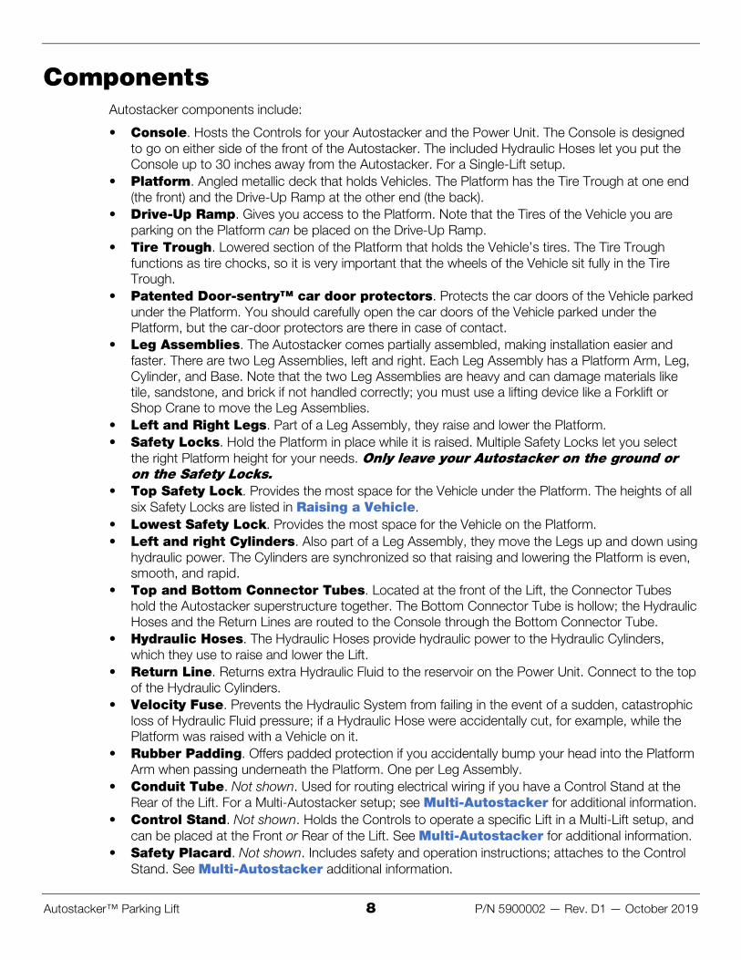
Important: The Bottom Connector Tube must be oriented so that the smaller gap (from the top Bolts to the top of the tube) must be at the top and the larger gap (from the bottom Bolts to the bottom of the tube) must be at the bottom. If you cannot push the Bolts through the Bottom Connector Tube and into the holes on the base of the Leg Assembly, it is probably because you have the Bottom Connector Tube oriented wrong.
Not all components shown. View is front of Autostacker facing towards Rear. 2. Take four Bolts from the Parts Box, then use them to connect one end of the Bottom Connector
Tube to the base of one of the Leg Assemblies.
3. Take four more Bolts from the Parts Box, then use them to connect the other end of the Bottom Connector Tube to the base of the other Leg Assembly.
4. Use a Forklift or Shop Crane to lift the two Leg Assemblies onto the lowest Safety Lock.
Raising the Leg Assemblies gives you some extra room as you continue installing the Autostacker.
5. Take three Bolts from the Parts Box, then use them to connect one end of the Top Connector Tube to the corresponding end of a Platform arm.
Tip The Top Connector Tube is heavy; you need at least two people to connect it (one person to hold the tube in place, one to connect the tube using the Bolts) or use a Forklift or Shop Crane to hold it in place while you connect it.
6. Take three more Bolts and use them to connect the other end of the Top Connector Tube to the corresponding end of a Platform Arm.

Autostacker™ Parking Lift 21 P/N 5900002 — Rev. D1 — October 2019
Anchor Bases to the Ground Both Autostacker Bases have three holes in them for anchoring the base to the ground, with two holes placed in the front of each Leg Assembly and one located in the back.
Tip If you prefer, you can defer anchoring the Autostacker Bases into place until later in the installation. Simply return to this section when you are ready.
Before you anchor your Autostacker, make sure the Leg Assemblies are correctly aligned.
CAUTION Poor alignment can affect how the Autostacker raises and lowers. Take the time ؍now, before you anchor the Autostacker in place, to make sure it is correctly aligned.

Autostacker™ Parking Lift 22 P/N 5900002 — Rev. D1 — October 2019
To check your Autostacker alignment prior to anchoring:
1. Using the drawing as a guide, measure A and B to make sure your Leg Assemblies are parallel. If the values are different, adjust as necessary.
2. Measure 1 and 2 to check your diagonal measurements. If the values are different, adjust as necessary.
3. When you believe your Leg Assemblies are parallel and the diagonals are correct, check your measurements again!
Important: Poor alignment can affect how your Autostacker raises and lowers. Re-aligning the Leg Assemblies after you anchor them into place is difficult. It is well worth your time to align your Autostacker correctly before you anchor it into place.
Concrete specifications are:
• Depth: 4.25 inches • PSI: 3,000 PSI, minimum • Cured: 28 days, minimum
Anchor Bolt specifications are:
• Length: 4.75 inches • Diameter: .75 inch • Anchor torque: 85 – 95 pound feet
The following drawing shows the locations of the Anchor Bolt holes in the bases. Other components have been removed so you can focus on the holes.

Autostacker™ Parking Lift 23 P/N 5900002 — Rev. D1 — October 2019
To anchor your Autostacker to the ground:
1. Double check to make sure the Autostacker Bases are where you want them.
Once Anchor Bolts are torqued into position, they are not easily removed.
Make sure the Leg Assemblies are correct before anchoring.
2. Using the holes in the Autostacker Bases as guides, drill the holes 4 inches deep.
Go in straight; do not let the drill wobble.
CAUTION Do not drill all the way through the Concrete; if you punch completely through the ؍slab, you could compromise the holding strength of the Anchor Bolt.
Use a carbide bit (conforming to the current ANSI B212.15).
The diameter of the drill bit must be the same as the diameter of the Anchor Bolt. So if you are using a ¾ inch diameter Anchor Bolt, for example, use a ¾ inch diameter drill bit.
3. Clean each hole.
Use a wire brush, vacuum, hand pump, or compressed air.
Do not ream the hole. Do not make the hole any wider than the drill bit made it.

Autostacker™ Parking Lift 24 P/N 5900002 — Rev. D1 — October 2019
Important: The holding strength of an Anchor Bolt is partly based on how cleanly the Expansion Sleeve presses against the Concrete. If the hole is dirty, the Expansion Sleeve does not press as cleanly. If the hole is too wide, the Expansion Sleeve does not press with as much force. Both result in less holding strength.
4. Make sure the Washer and Nut are in place, then insert the Anchor Bolt into the hole.
The Expansion Sleeve of the Anchor Bolt may prevent the Anchor Bolt from passing through the hole in the Base; this is normal. Use a hammer or mallet to get the Expansion Sleeve through the Base and into the hole.
Even using a hammer or mallet, the Anchor Bolt should only go into the Hole part of the way; this is normal. If the Anchor Bolt goes all the way in with little or no resistance, the hole is too wide.
Once past the hole in the Base, the Anchor Bolt eventually stops going down into the hole as the Expansion Sleeve contacts the sides of the hole; this is normal.
5. Hammer or mallet the Wedge Anchor the rest of the way down into the hole.
Stop hammering when the Washer is snug against the Base.
6. Wrench each Nut clockwise to the recommended installation torque, 85 – 95 pound feet, using a Torque Wrench.
Important: Do not use an impact wrench to torque the Anchor Bolts.
Wrenching the Nut forces the Wedge up, pushing out the Expansion Sleeve and pressing it tightly against the Concrete.

Autostacker™ Parking Lift 25 P/N 5900002 — Rev. D1 — October 2019
Assemble the Console and Attach the Power Unit The Console can go on either side of the front of the Autostacker. The Console only works with Single-Lift configurations.
Note: The Console comes unassembled from the factory. This section describes how to assemble the Console and attach the Power Unit inside the Console.
Tip If you wish to place the Console further than 30 inches from your Autostacker, you will need to get Hydraulic Hoses that are long enough to reach the Autostacker from where you want to put the Console. These should be relatively easy to obtain from the local hydraulics shop, once you know how long you need the Hoses. You will also need a longer Return Line.
The following drawing shows the components that make up the Console.

Autostacker™ Parking Lift 26 P/N 5900002 — Rev. D1 — October 2019
The following procedure includes instructions for anchoring the Console into place. If you prefer, you can defer anchoring the Console into place for later. Simply return to this section when you want to anchor the Console into place.
To assemble the Console and attach the Power Unit:
1. Select a site for the Console that permits operators to have a full, unobstructed view of the Lift.
If you are going to use the included Hydraulic Hoses, the Console needs to be near the front of the Autostacker; it can go on either side, up to 30 inches away.
2. Arrange all of the Console components near where you are going to assemble it.
3. Lay the Back Plate flat on the ground, with the Mounting Bracket for the Power Unit facing up.
4. Put the Grommets into place in the Grommet Holes on the bottom of the Left and Right sides.
5. Put the Left Side on the left and the Right Side on the right, then attach both of them to the Back.
Note that the Flanges on the bottoms of both sides need to be on the inside and the Back attaches on the outside of the two sides.
Do not attach the Nuts at the top of the sides or the Back at this point; these will be attached later when you are ready to attach to the Top of the Console.
6. Remove the Power Unit from its packing material.
7. Stand up the Console, then using the supplied Nuts and Bolts, attach the Power Unit to the Power Unit Plate.
8. Attach the Power Disconnect Switch; one piece goes on the inside of the Right Side, the clear piece goes on the outside of the Right Side; use four screws to connect the clear piece on the outside to the inside piece, then add the red/yellow switch on the outside using a single screw.
Important: All of the components of the Console are now in place, but they are not all connected. To connect the Hydraulic Hoses, Return Lines, and the other connections to the Power Unit, you are going to need to remove both the Top of the Console and the Front. See Connect the Power Unit for more information.
9. If you are ready to anchor the Console in place, find the four holes in the bottom of the Console base (on the inside) and mark the locations; the four Anchor Bolts go in those holes.
10. Move the Console out of the way.
It is much easier to drill the holes for the Anchor Bolts if the Console is out of the way.
11. Drill four holes 3/8" wide by 2.5" deep in the concrete floor at the locations you just marked.
Go in straight; do not let the drill wobble. Use a carbide bit (conforming to the current ANSI B212.15).
12. Remove all dust from the Holes.
Use a wire brush, vacuum, hand pump, or compressed air. Do not ream the Hole. Do not make the hole any wider than the drill bit made it.
13. Move the Console over the four holes.
14. Insert an Anchor Bolt with Washer into each hole, then tap it down into the hole.
15. Wrench the Anchor Bolt clockwise to the recommended installation torque, 85-95 pound feet, using a Torque Wrench.

Autostacker™ Parking Lift 27 P/N 5900002 — Rev. D1 — October 2019
Connect the Hydraulic Hoses Hydraulic Hoses provide hydraulic power to the Hydraulic Cylinders, which is used to raise and lower the lift.
If you have a Multi-Lift setup, this procedure will be different for you; see Multi-Autostacker towards the end of this manual for modified instructions.
The Autostacker comes with two Hydraulic Hoses, of different lengths:
• Short Hydraulic Hose. Goes from the Power Unit to the Hydraulic Cylinder closest to the Console.
• Long Hydraulic Hose. Goes from the Power Unit to the Hydraulic Cylinder furthest from the Console.
Both Hydraulic Hoses are routed through the Bottom Connector Tube, which is hollow.
The following drawing shows how the Hydraulic Hoses are routed to the Hydraulic Cylinders.
The following drawing is a close-up of the connections to make to the Hydraulic Cylinders.

Autostacker™ Parking Lift 28 P/N 5900002 — Rev. D1 — October 2019
To connect the Hydraulic Hoses:
1. Locate the two Hydraulic Hoses that come with your Lift.
2. Starting near the Console, route the Long Hydraulic Hose through the Bottom Connector Tube and pull it out at the Hydraulic Cylinder that is furthest away from the Console.
Leave enough Hose on the Console end to allow the Long Hydraulic Hose to be connected to the Power Unit up through one of the openings at the bottom of the Console.
Pull out enough of the Hydraulic Hose to reach the Connector with Two Nuts when it is time to put all of the components together.
3. Starting near the Console, route the short Hydraulic Hose through the Bottom Connector Tube and pull it out at the Hydraulic Cylinder nearest to the Console.
Leave enough of the Hydraulic Hose on the Console end to allow the Short Hydraulic Hose to be connected to the Power Unit up through one of the openings at the bottom of the Console.
Pull out enough of the Hydraulic Hose to reach the Connector with Two Nuts when it is time to put all of the components together.
4. For both Hydraulic Cylinders, install Velocity Fuses in the connectors near the bottom of each Hydraulic Cylinder. Finger tighten the connection.
Refer to About Velocity Fuses for more information.
5. For both Hydraulic Cylinders, remove one Nut from the Connector with Two Nuts, put the Connector with Two Nuts into the Connector Weldment, put the Nut you just removed back onto the Connector with Two Nuts, and finger tighten both Nuts around the Connector Weldment.
6. For both Hydraulic Cylinders, connect the Hydraulic Line Assembly to the top end of the Connector with Two Nuts and the other end to the top end of the Velocity Fuse.
Finger tighten all connections.
7. For both Hydraulic Cylinders, connect the Hydraulic Hose to the bottom end of the Connector with Two Nuts.
Finger tighten the connections.
8. Attach two 90° connectors (FTB ELB -04 JIC -06L ORB) to both Hydraulic Power connectors on the Power Unit.
There are two Hydraulic Power connectors on a Power Unit, in varying locations (depending on the Power Unit you have). Refer to Connect the Power Unit to identify your layout.
9. Route the two Hydraulic Hoses, one at a time, through an opening along the bottom of the Console and up to one of the 90° connectors, then connect them. It does not matter which Hydraulic Line goes to which Hydraulic Power connector.
10. Once all connections have been made, use the appropriate tools to fully tighten all of the finger-tightened connections.

Autostacker™ Parking Lift 29 P/N 5900002 — Rev. D1 — October 2019
Connect the Return Lines The Return Lines take extra Hydraulic Fluid from the Hydraulic Cylinders and returns it to the Power Unit’s Hydraulic Fluid Reservoir; it also allows air to move in and out of the Hydraulic Cylinders.
One end of the Return Line connects to the Power Unit (where it goes into the Reservoir). There are two other ends; they attach to Return Line connectors, which are near the top of each Hydraulic Cylinder.
The Return Line comes as one long roll of tubing; you need to cut it into sections of the right length.
If you have a Multi-Lift setup, this procedure will be slightly different for you; see Multi-Autostacker for modified instructions.
The following diagram shows how the Return Lines should be arranged.
Tip If you want, you can use zip ties (also called cable ties, not supplied) to hold the Return Lines in place once they are connected.
You are going to need three Return Line segments of varying length:
• From the Power Unit to the T connector • From the T connector to the Return Line connector on the Hydraulic Cylinder nearest the Console • From the T connector to the Return Line connector on the Hydraulic Cylinder furthest from the
Console

Autostacker™ Parking Lift 30 P/N 5900002 — Rev. D1 — October 2019
Working with Return Lines and Compression Fittings Autostacker uses Return Lines made of a roll of ¼ inch, polyethylene Tubing (also called Poly-Flo®) that is used with Compression Fittings to attach to the Air Cylinders and the Return Line Connectors.
The components involved with Compression Fittings include:
• ¼ inch, black, polyethylene Tubing. The Return Lines require several lengths of tubing to make the necessary connections back to the Console.
• Elbow Compression Fittings (also called a 90° fitting). The Return Lines use Elbow Fittings to attach to each Hydraulic Cylinder and one that connects to the Console.
• Tee Compression Fitting. The two Return Lines hooked up to the Hydraulic Cylinders connect to a Tee Compression Fitting that goes back to the Power Unit.
• Nuts, Ferrules, Rods, and Threads. Each connector on Elbow and Tee Compression Fittings have a Nut, Ferrule, Rod, and Threads. The Nut holds the tubing and Fitting together. The Ferrule compresses when you tighten the Nut on the Threads to make a secure connection. The Rod goes inside the Tubing so that there are no leaks.
The following drawing shows the components of a connector on a Tee Compression Fitting
Important: Ferrules can only be tightened once. When you tighten the Nuts on the Threads, the Ferrules get compressed; it changes shapes and cannot be used again.
To connect the Return Lines:
1. Attach a 90° Fitting (Elbow Fitting -04 COMP x -06 NPT) to one of the two Return Line connectors on the Power Unit.
There are two Hydraulic Return connectors on the Power Unit, one on each side; they work the same, so choose the one that is best for you. You only need to use one, not both. They are shown in the drawing in Connect the Power Unit.
2. Attach a 90° Fitting (Elbow Fitting -04 COMP x -04 NPT) to both Return Line Connectors near the top of each Hydraulic Cylinder.
3. Locate a T Connector and put it near the bottom of the Hydraulic Cylinder closest to the Console.
4. Locate the Return Line tubing.
5. Cut a piece of tubing of appropriate length for each of the three Return Line segments.
6. Connect a Return Line between the Power Unit and the T Connector.
7. Connect a Return Line between the T Connector and the Return Line connector on the Hydraulic Cylinder nearest the Console.
8. Connect the final Return Line to the T Connector, route it through the Bottom Connector Tube, then connect it to the Return Line connector on the Hydraulic Cylinder furthest from the Console.

Autostacker™ Parking Lift 31 P/N 5900002 — Rev. D1 — October 2019
Connect the Power Unit The Power Unit comes assembled from the factory. You need to attach it to the back of the Console and then connect it properly, described in this section.
If you have a Multi-Lift setup, this procedure will be different for you; see Multi-Autostacker for more information.
The Power Units that can be used with your Autostacker include either 110 VAC, 220 VAC at 50/60 Hz, 1 Ph or 380 VAC at 50 Hz, 3 Ph.
.DANGER All wiring must be performed by a licensed, certified Electrician ؍
Refer to Wiring Diagrams for wiring information.
.CAUTION The Power Unit’s motor is not thermally protected ؍
The Power Unit has multiple connections:
• Two Hydraulic Hoses and One Return Line. Already in place and connected. • Power Cable. The Power Cable on the Power Unit connects to the top of the Power Disconnect
Switch. A licensed, certified Electrician is required for this connection. • Power Source. The Power Source connects to the bottom of the Power Disconnect Switch.
Also requires a licensed, certified Electrician. • Controls. The Female (Molex™) Connector on the Power Unit connects to a Male Connector
coming down from the Controls in the Top of the Console.
The following diagram shows a sample Autostacker Power Unit.
Autostacker™ Parking Lift 32 P/N 5900002 — Rev. D1 — October 2019
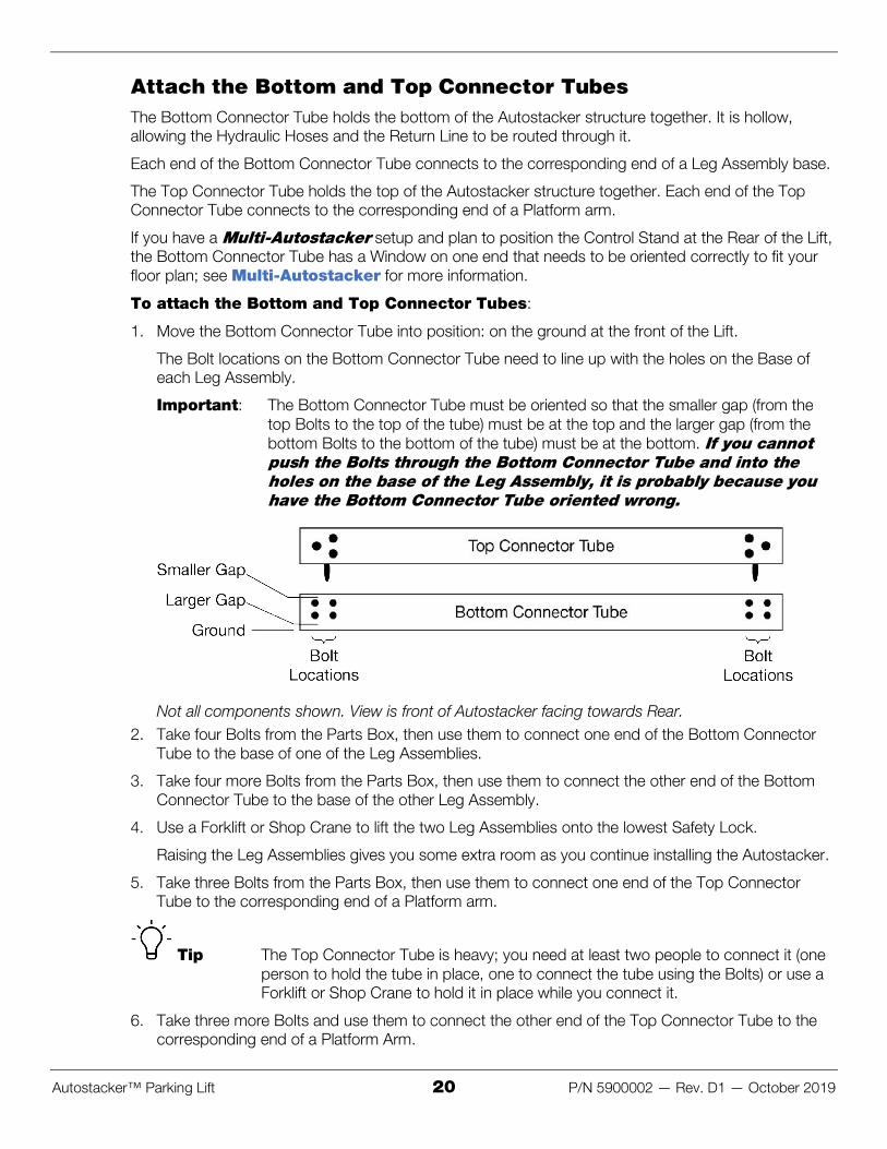
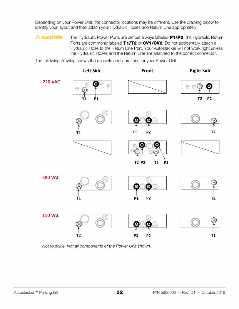
Depending on your Power Unit, the connector locations may be different. Use the drawing below to identify your layout and then attach your Hydraulic Hoses and Return Line appropriately.
CAUTION The Hydraulic Power Ports are almost always labeled P1/P2; the Hydraulic Return ؍Ports are commonly labeled T1/T2 or CV1/CV2. Do not accidentally attach a Hydraulic Hose to the Return Line Port. Your Autostacker will not work right unless the Hydraulic Hoses and the Return Line are attached to the correct connector.
The following drawing shows the possible configurations for your Power Unit.
Not to scale. Not all components of the Power Unit shown.

Autostacker™ Parking Lift 33 P/N 5900002 — Rev. D1 — October 2019
To make connections to the Power Unit and add Hydraulic Fluid:
1. Remove the Top and Front of the Console if they are currently in place.
2. Locate the Female (Molex™) Connector on the Power Unit and attach it to the Male Connector that comes from the Controls in the Top of the Console.
Make sure to orient the two Connectors correctly.
3. Have an Electrician connect the Power Cable on the Power Unit to the top of the Power Disconnect Switch.
4. Have an Electrician connect your selected VAC power source to the bottom of the Power Disconnect Switch.
Refer to Wiring Diagrams for proper wiring information. Note that the cord from the power source to the bottom of the Power Disconnect Switch is not supplied.
DANGER All wiring must be performed by a licensed, certified Electrician. Do not perform ؍any maintenance or installation on the lift without first making sure that main electrical power has been disconnected from the lift and cannot be re-energized until all procedures are complete.
Important electrical information:
• Improper electrical installation can damage the Power Unit motor; this damage is not covered under warranty.
• Use a separate circuit breaker for each Power Unit. • Protect each circuit with a time-delay fuse or circuit breaker.
– For a 220 VAC, single phase circuit, use a 25 amp or greater fuse. – For a 380 VAC, three-phase circuit, use a 20 amp or greater fuse.
• Position the Power Unit near the circuit breaker and incoming power source; for Power Units placed at a larger distance away, consult your Electrician.
• Use the proper wire size for your Power Unit. – For 220 VAC, 50 Hz, 1 Ph or 208-230 VAC, 60 HZ, 1 Ph, 2 HP, use a minimum 12 AWG
wire. – For a 380 VAC, 50 Hz, 3 Ph, 2 HP, use a minimum 12 AWG wire. – For a 110 VAC, 50/60 Hz, 1 Ph, use a minimum 10 AWG wire.
5. Have an Electrician check all connections for loose wiring.
6. Fill the Hydraulic Fluid reservoir.
The Power Unit’s Hydraulic Fluid reservoir must be filled with Hydraulic Fluid or Automatic Transmission Fluid before you begin operation. When you receive it, the reservoir is empty; the Power Unit will not work correctly until it is filled with approved fluids.
Approved fluids are any general purpose ISO-32, ISO-46, or ISO-68 hydraulic oil or approved automatic transmission fluids such as Dexron III, Dexron VI, Mercon V, Mercon LV, or any synthetic multi-vehicle automatic transmission fluid.
WARNING Do not run your Power Unit without Hydraulic Fluid; you will damage it. Keep the ؍Power Unit dry; damage to the Power Unit caused by water, detergents, acid, and other liquids is not covered by the warranty.

Autostacker™ Parking Lift 34 P/N 5900002 — Rev. D1 — October 2019
Wiring a Power Disconnect Switch
DANGER All wiring must be performed by a licensed, certified Electrician. Do not perform ؍any maintenance or installation on the Lift without first making sure that main electrical power has been disconnected from the lift and cannot be re-energized until all procedures are complete.
WARNING User-supplied wiring connects to the wiring inside the Electrical Box; remove the ؍front cover to access the inside. Do not accidentally connect to the electrical components on the underside of the Console Top.
The following diagram shows the components related to installing a Power Disconnect Switch.
Drawing not to scale. Not all components shown. Only connect Molex connectors to each other.

Autostacker™ Parking Lift 35 P/N 5900002 — Rev. D1 — October 2019
DANGER Do not perform the following procedure until you are certain the Power Unit is ؍disconnected from power and cannot be re-energized. All electrical work must be performed by a licensed, certified Electrician. If your organization has Lockout/Tagout policies, make sure to implement them after connecting to a power source.
To install the Power Disconnect Switch on an Autostacker:
1. Remove the two screws from the sides of the Electrical Box and remove the cover.
2. Locate the three available wires: Black (Hot), White (Hot), and Green (Ground).
3. Connect the three available wires to a User-supplied wiring.
4. Connect the two Hot wires, Black and White, to the top of the Power Disconnect Switch.
5. Route the Green (Ground) wire around the Power Disconnect Switch to the User-Supplied Power Cord.
6. Attach the Brown (Hot) and Blue (Hot) wires in the User-Supplied Power Cord to the bottom of the Power Disconnect Switch.
7. Replace the cover of the Electrical Box and screw it back on.
8. Attach a Cable Clip to the inside of the Console, to hold the Power Cord securely; Cable Clips also help support the weight of the Power Cord.
Cable Clips are not supplied with the Power Unit.
9. Connect the User-Supplied Power Cord to an appropriate power source.
Install a Thermal Disconnect Switch
WARNING The Autostacker comes with a Power Disconnect Switch, but the Autostacker ؍motor has no thermal overload protection.
Have an Electrician connect a Thermal Disconnect Switch or overload device that will make sure the equipment shuts down in the event of an overload or an overheated motor.
DANGER Installing a Thermal Disconnect Switch must be performed by a licensed, certified ؍Electrician. Do not perform any maintenance or installation on the lift without first making sure that main electrical power has been disconnected from the lift and cannot be re-energized until all procedures are complete.
High running amps that exceed the motor’s full load amps (FLA) rating may result in permanent damage to the motor.
Autostacker strongly recommends you not exceed the rated duty cycle of the Autostacker motor.

Autostacker™ Parking Lift 36 P/N 5900002 — Rev. D1 — October 2019
Test the Autostacker Before putting your Autostacker into normal operation, we recommend breaking it in by raising and lowering it a few times. This will help you get a feel for how to operate it and also helps to get any residual air out of the hydraulic system.
Tip Residual air in the hydraulic system can cause the Autostacker to shake, move erratically, or squeak; this is normal. If it happens to you, do not worry; it will go away quickly as the Autostacker is self-bleeding.
Neither the Platform nor the Drive-On Ramp need to be installed to test the lift. You also do not need weight on the Lift.
Note: The Autostacker lowers a little slower with no weight on it.
To test your Autostacker:
1. Check the area around and above the Autostacker for obstructions.
Move them if you find any.
2. Insert the key and move it to the On position.
3. Press and hold Up.
The Autostacker starts rising.
4. Before reaching the first Safety Lock, release Up.
The Autostacker stops rising.
5. Press and hold Down.
The Autostacker starts lowering.
6. When the Autostacker gets to the ground, it stops lowering; release Down.
7. Wait for one minute.
WARNING The Autostacker’s Power Unit is not a constant duty motor; it cannot be run ؍continuously.
8. Repeat the process, this time raising the Autostacker just past the first Safety Lock.
You can tell when the Autostacker passes a Safety Lock: when the Lock Hood goes past a Lock Block, it hits the base and makes an audible click. Refer to About Safety Locks for more information.
9. If the Autostacker is working without shaking, moving erratically, or squeaking, there is no need to repeat the procedure.
If the Autostacker is shaking, moving erratically, or squeaking, repeat the procedure one more time, raising the Autostacker to the second Safety Lock.
It is normal for the Autostacker to shake, move erratically, or squeak when you first get it. Using it a few times almost always fixes those issues.
If your Autostacker continues to have problems well past the break-in period, refer to Troubleshooting for additional information.

Autostacker™ Parking Lift 37 P/N 5900002 — Rev. D1 — October 2019
Add the Tire Trough and Tire Stops The Tire Trough is a lowered section of the Platform that holds the tires of the Vehicle. The Tire Stops attach to the top of the Tire Trough and add a bit of extra height for holding Vehicles with larger tires.
Important: The Tire Trough functions as a tire chock; the forward wheels of the Vehicle on the Platform should always be sitting fully in the Tire Trough.
The Tire Trough is installed at the front of the Autostacker; it attaches to the Top Connector Tube.
The Tire Stops are optional but recommended. They attach to the Top Connector Tube using the same Nuts, Bolts, and Washers as the Tire Trough.
WARNING The Tire Trough is heavy. Move it into position using a lifting device such as a ؍Forklift or Shop Crane. If this is not an option, have at least two people to move it. Do not allow just one person to move the Tire Trough; they could be injured.
To install the Tire Trough and Tire Stops:
1. Move the Tire Trough into position next to the Top Connector Tube.
A section of the Tire Trough rests on the Top Connector Tube. This is where the Tire Stops go and where you attach the Tire Trough to the Top Connector Tube.
2. Get the necessary Bolts (4), Nuts (4), and Washers (8) from the Parts Bag.
3. Put the Tire Stops on top of the Tire Trough; align the holes in the bottom of the Tire Stops with the holes in the Tire Trough and the Top Connector Tube.
Orient the Tire Stops so that the vertical portion is on the Tire Trough side.
4. Push a Washer into place on the Bolt, then slide the Bolt through the Tire Stop, the Tire Trough, and the Top Connector Tube.
5. Put the second Washer on the Bolt, at the bottom, then add and tighten the Nut.
The following drawing is a side view of how these components go together.
6. Repeat steps 4 and 5 for each of the other holes.

Autostacker™ Parking Lift 38 P/N 5900002 — Rev. D1 — October 2019
Add the Platform Sections and the Drive-Up Ramp The Platform sections, when installed, create the Platform. The Drive-Up Ramp lets you drive a vehicle onto the Platform. The Platform sections are most easily installed from underneath. Raise the Autostacker to a height that is good for you.
.WARNING Do not go under the Autostacker until it is securely on a Safety Lock ؍
Start next to the Tire Trough. Add one Platform section at a time. Put each one in place, then use the Nuts and Bolts to secure them. There are three Nuts and Bolts per Platform section: one on each end, to connect the Platform section to the structure, and one in the middle, to attach the Platform section to the previous section.
When you get to the Drive-Up Ramp, it secures only on the sides, not in the middle.
To add the Platform sections and the Drive-Up Ramp:
1. Starting next to the Tire Trough, put a Platform section next to the Tire Trough and then slide the end closest to the Tire Trough under it slightly; bolt the ends of the Platform section into the Platform Arm.
2. Put the next Platform section into place against the first one.
You know the two are oriented correctly when the holes line up.
3. Attach the Platform sections to each other by putting in a Nut and Bolt in their center holes.
It is not necessary to put in all of the Nuts and Bolts now; wait until all of the sections are in place.
4. Attach the rest of the Platform sections to each other, one at a time, keeping them in place by putting a Nut and Bolt in the center holes.
5. When the last Platform section is in place, move the Drive-Up Ramp into place.
If it makes installation easier, you can lower the lift to a more appropriate height.
WARNING The Drive-Up Ramp is heavy. Move it into position using a lifting device such as a ؍forklift or crane. If this is not an option, use at least two people to move it. Do not allow just one person to move the Drive-Up Ramp; they could be injured.
The end of the last Platform section and the top of the Drive-Up Ramp need to overlap.
6. When the Drive-Up Ramp is correctly oriented, connect it to the Platform Arm using three Nuts and Bolts on each side.
7. Check to make sure all of the Platform pieces and the Drive-Up Ramp are correctly positioned.
8. Put in the rest of the Nuts and Bolts that attach the Platform sections to each other.
9. Push the Rubber Padding up into place along the outside Rail of each Leg, at the Rear of the Lift.
The Rubber Padding help in case you bump your head when passing underneath the Platform; they come in the Parts Box and are about 38 inches long.
Not all components shown. Drawing is a side view of the Platform. One Rubber Edge per Leg.

Autostacker™ Parking Lift 39 P/N 5900002 — Rev. D1 — October 2019
Lubricate the Lift The Autostacker has eight Lubrication Points, four on each Leg Assembly.
You must grease the Threaded Grease Fitting at the Lubrication Points before you start normal operation of your Autostacker. Refer to Maintenance for more information about how often to grease the Lubrication Points after the start of normal operation.
Tip Autostacker recommends using white lithium grease, or similar, and a grease gun with an appropriate tip (a Lube-Link™, for example) when lubricating your lift.
The Threaded Grease Fittings / Lubrication Points on each Leg Assembly are:
• Where the bottom of the Cylinder meets the Base • Where the top of the Cylinder meets the Leg • On the underside where the two Legs cross • Where the Leg meets the Top Connector Tube
Autostacker™ Parking Lift 40 P/N 5900002 — Rev. D1 — October 2019
Final Checklist Make sure these things have been done before using your lift:
• Review the Installation Checklist to make sure all steps have been performed. • Make sure the Power Unit is getting power from the power source. • Check the Power Unit’s Hydraulic Fluid reservoir; it must be full of approved Hydraulic Fluid or
automatic transmission fluid. You can harm the motor by running it without enough fluid. • Check the Hydraulic System for leaks. • Check to see that all Anchor Bolts are properly tightened. • Make sure that all Safety Locks are cleared and free. • Make sure a copy of the Installation and Operation Manual is left with the equipment, so that it is
available to all operators, and make sure all labels are visible. • Raise the Autostacker to each of the six Safety Locks and measure the space between the ground
and the bottom of the Drive-Up Ramp. Check these values against the values shown in Raising a Vehicle. These are the actual values that you should use to determine what Vehicles you want to put where.
• Perform an operational test of the Lift with a typical Vehicle.
During the operational test, observe all operating components and check for proper installation and operation. Do not raise any additional vehicles until a thorough operational check has been performed with a typical Vehicle.
If the Autostacker fails the operational test, take it out of service, then consult Troubleshooting to begin addressing the problem.

Autostacker™ Parking Lift 41 P/N 5900002 — Rev. D1 — October 2019
Operation This section describes how to operate your Autostacker.
WARNING Always use care when you are around the Autostacker. When it is lowered, be ؍careful not to trip over it. When it is raised, be careful not to bang your head on the Drive-Up Ramp or Platform. When the Autostacker is moving, keep all people, animals, and objects at least 30 feet away from it.
Preparing to Raise or Lower a Vehicle Before you raise or lower a Vehicle using Autostacker, do the following:
• Check the Autostacker. Check the Autostacker for any missing, heavily worn, or damaged parts. Do not operate the Autostacker if you find any issues; instead, take the Lift out of service, then contact your Autostacker dealer, visit autostacker.com/support, email [email protected], or call Autostacker at (888) 977-8225.
• Check the area. Check the area around the Autostacker for obstructions; anything that might block the lift. Do not forget to check above the Autostacker. If you find an obstruction, move it out of the way. Do not allow people or animals within 30 feet of the Autostacker while it is in motion.
• Check the operators. Make sure that everyone who is going to operate the Autostacker has been trained in its use, has read the labels on the unit, and has read the manual. Only the operator at the Console should be within 30 feet of the Autostacker when it is in motion.
• Check for safety. Make sure everyone who is going to be walking near the Autostacker is aware of its presence and takes appropriate safety measures. Only put Vehicles on the Platform. When raising the Autostacker, do not leave it until it is on a Safety Lock. When lowering the Autostacker, do not leave it until it is on the ground. Do not allow children to operate the Lift. Do not allow anyone under the influence of drugs or alcohol to operate the Lift.
The Autostacker Console Your Autostacker is controlled via its Console.
The parts of the Autostacker Console are:
• Emergency Stop button. Press to immediately stop the Autostacker from moving. This button is for use in unexpected or dangerous situations.
• On/Off key. Insert the key and turn it to On when you want to raise or lower the Lift. Set it to Off and remove the key when the Lift is not in use. Do not leave the key in all the time; this is a security and safety risk.
• Up button. Press and hold Up to raise the Lift. Release Up to stop the Lift from going up. • Down button. Press and hold Down to lower the Lift. Release Down to stop the Lift from going
down. The alert sound goes on automatically when the Lift is moving down.

Autostacker™ Parking Lift 42 P/N 5900002 — Rev. D1 — October 2019
Raising a Vehicle This section describes how to position a Vehicle on the Autostacker and raise it.
To raise a Vehicle:
1. Make sure the Platform is fully lowered, then drive the Vehicle onto the Platform, either nose first or backed in.
CAUTION When driving a Vehicle onto or off of the Platform, keep to the middle of the ؍Platform. Also, be careful driving onto the Platform with a Vehicle that has wet tires, it can be difficult for the wheels to gain traction.
2. Put the Vehicle’s forward wheels into the Tire Trough. The wheels must be in the Tire Trough.
3. Put the Vehicle in park, put on the parking brake, and turn off the Vehicle.
If the Vehicle is a manual transmission, put it into first gear before turning off the Vehicle.
4. Get out of the Vehicle and make sure the forward wheels are securely in the Tire Trough.
If the forward wheels are not situated correctly in the Tire Trough, get back into the Vehicle and reposition the wheels; the Rear Wheels must fit on the Platform or Drive-up Ramp.
5. Double check that there are no obstructions that will interfere with the raising of the Lift.
6. At the Console, insert your key, turn it to On, then press and hold the Up button.
7. Watch the Vehicle and the lift as they rise.
If the Lift becomes unstable or the Vehicle starts moving on the Platform, press the red Emergency Stop button.
8. When the Platform passes the desired height, release the Up button. The Lift stops rising.
9. Press the Down button to move the Lift down onto the most recently passed Safety Lock.
Tip If you move the Lift too far past a Safety Lock, it will not catch on the way back down. If this happens, simply move the Lift back up again, just past the Safety Lock, and then lower it back down onto the Safety Lock.
The Safety Lock heights are:
– Top Safety Lock: 81" / 6.9' / 2,057 mm of space under Platform
– Second Safety Lock: 76.25" / 6.4' / 1,936 mm of space under Platform
– Third Safety Lock: 71.25" / 5.11' / 1,809 mm of space under Platform
– Fourth Safety Lock: 65.5" / 5.5' / 1,663 mm of space under Platform
– Fifth Safety Lock:: 59" / 4.11' / 1,498 mm of space under Platform
– Lowest Safety Lock: 51.75" / 4.4' / 1,314 mm of space under Platform
Using the top Safety Lock frees up more space for the Vehicle you are parking under the Platform; using the lowest Safety Lock frees up more space for the Vehicle you are parking on the Platform.
Note: Depending on the installation, these figures can vary 1/2 an inch in either direction. If your measurements indicate that your Vehicle is too close to these heights, raise the Lift to the next Safety Lock. If the Platform is already on the highest Safety Lock, and there is still not enough space available, you cannot park that particular Vehicle underneath the Platform.

Autostacker™ Parking Lift 43 P/N 5900002 — Rev. D1 — October 2019
About Safety Locks Each Leg Base has six Safety Locks; they serve two important functions:
• Safety. Safety locks hold the Platform in place. Once your Autostacker is on the Safety Lock Blocks, the weight of the Vehicle pressing down holds the Platform in place without requiring any energy. If you turn the Power Unit off or if the power goes out, the Safety Locks holds the Platform, and anything on it, in place.
WARNING Do not walk under your Autostacker or leave the area until you have confirmed that ؍both Safety Locks are secured in place. Although rare, it is possible for hydraulic fluid in the Cylinders to leak, causing the Lift to slowly come down. When you are operating an Autostacker, only leave it on the ground or on the Safety Locks.
• Space. As described above, putting your Autostacker into the top Safety Lock gives you the most space under the Platform for another Vehicle. When you use the lowest Safety Lock, you have more available space for a larger Vehicle on the Platform.
To put your Autostacker onto a Safety Lock:
1. Press Up to raise the Platform.
The following drawing shows the Lock Cam and Lock Hood passing over a Lock Block.
The Lock Hood is partway over the Lock Block; the Lift would not go on a Safety Lock at this point.
:WARNING ؍
Do not walk under the Lift or leave the area until you have confirmed both Safety Locks are securely on a locking position. Failure to do so could result in personal injury and/or product damage.
2. When the Lock Hood goes past a Lock Block, it makes an audible click when it hits the base.
The following drawing shows the Lock Cam and the Lock Hood at different places in relation to the Lock Block.
The Lock Hood is at the same level as the Lock Block; if you were to start backing down at this point, the Lift would go onto a Safety Lock.

Autostacker™ Parking Lift 44 P/N 5900002 — Rev. D1 — October 2019
3. To use that Safety Lock, keep pressing Up for another half a second, then release Up.
4. Press Down for a few seconds; the Lock Hood moves into a locked position on the Lock Block it just passed.
The Lock Hood is securely on the Lock Block.
5. If you miss the desired Safety Lock, there’s no problem; just try it again until you get it right.
Parking a Vehicle Under Autostacker This section describes how to park a Vehicle under the Autostacker Platform.
To park a Vehicle under the Platform:
1. Check the height of the Vehicle against the amount of space that is available under the Autostacker Platform; there needs to be enough space to accommodate the height of the Vehicle.
2. If necessary, raise the Autostacker Platform to a higher Safety Lock.
If the Autostacker Platform is already on the highest Safety Lock, and there still is not enough space available, you cannot park that particular Vehicle under the Autostacker Platform.
If desired, lower the Vehicle’s antenna and fold in any side mirrors.
3. Drive the Vehicle into the center of the space under the Autostacker Platform.
4. Put the Vehicle in park, put on the parking brake, and turn off the Vehicle.
If the Vehicle is a manual transmission, put it into first gear before turning off the Vehicle.
5. Open the car door(s) carefully, making sure not to bang the door against the Autostacker Legs.
Although the Autostacker comes with Patented Door-sentry™ car door protectors, you should always carefully open the car doors when exiting a Vehicle parked underneath the Platform.
6. Exit the Vehicle, taking care not to bump your head on the Autostacker Platform or trip over the Autostacker Bases.
7. To get the parked Vehicle back out again, simply reverse this process.

Autostacker™ Parking Lift 45 P/N 5900002 — Rev. D1 — October 2019
Lowering a Vehicle This section describes how to get a Vehicle off of the Autostacker Platform.
To lower a Vehicle:
1. Check the items listed in Preparing to Raise or Lower a Vehicle.
If you find any issues, resolve them before lowering the Vehicle.
2. At the Console, insert your key and turn it to On.
3. Press and hold the Up button to raise the Lift off of the Safety Lock.
The Lock Hood and Lock Cam move nearly to the next Lock Block in order to disengage completely from the Safety Lock Block it was secured on.
4. Once disengaged from the Lock Block, the Lock Cam will be facing down, as shown above.
Press and hold the Down button.
5. When the Autostacker Platform is resting on the ground, release the Down button.
6. Carefully drive the Vehicle off the Autostacker Platform.
7. Turn the key on the Console to Off, then remove it.
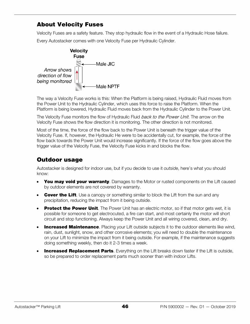
Autostacker™ Parking Lift 46 P/N 5900002 — Rev. D1 — October 2019
About Velocity Fuses Velocity Fuses are a safety feature. They stop hydraulic flow in the event of a Hydraulic Hose failure.
Every Autostacker comes with one Velocity Fuse per Hydraulic Cylinder.
The way a Velocity Fuse works is this: When the Platform is being raised, Hydraulic Fluid moves from the Power Unit to the Hydraulic Cylinder, which uses this force to raise the Platform. When the Platform is being lowered, Hydraulic Fluid moves back from the Hydraulic Cylinder to the Power Unit.
The Velocity Fuse monitors the flow of Hydraulic Fluid back to the Power Unit. The arrow on the Velocity Fuse shows the flow direction it is monitoring. The other direction is not monitored.
Most of the time, the force of the flow back to the Power Unit is beneath the trigger value of the Velocity Fuse. If, however, the Hydraulic He were to be accidentally cut, for example, the force of the flow back towards the Power Unit would increase significantly. If the force of the flow goes above the trigger value of the Velocity Fuse, the Velocity Fuse kicks in and blocks the flow.
Outdoor usage Autostacker is designed for indoor use, but if you decide to use it outside, here’s what you should know:
x You may void your warranty. Damages to the Motor or rusted components on the Lift caused by outdoor elements are not covered by warranty.
x Cover the Lift. Use a canopy or something similar to block the Lift from the sun and any precipitation, reducing the impact from it being outside.
x Protect the Power Unit. The Power Unit has an electric motor, so if that motor gets wet, it is possible for someone to get electrocuted, a fire can start, and most certainly the motor will short circuit and stop functioning. Always keep the Power Unit and all wiring covered, clean, and dry.
x Increased Maintenance. Placing your Lift outside subjects it to the outdoor elements like wind, rain, dust, sunlight, snow, and other corrosive elements; you will need to double the maintenance on your Lift to minimize the impact from it being outside. For example, if the maintenance suggests doing something weekly, then do it 2-3 times a week.
x Increased Replacement Parts. Everything on the Lift breaks down faster if the Lift is outside, so be prepared to order replacement parts much sooner than with indoor Lifts.

Autostacker™ Parking Lift 47 P/N 5900002 — Rev. D1 — October 2019
Maintenance DANGER: Before performing any maintenance on your Autostacker, make sure it is ؍
completely disconnected from power. If your organization uses Lockout/Tagout policies, make sure to implement them after connecting to a power source.
To maintain your Autostacker:
• Daily: Keep the Autostacker clean. Wipe up any spills, clean any dirt. • Daily: Make a visual inspection of all moving parts and check for damage or excessive wear.
Replace any damaged or worn parts before using the Lift. • Daily: Make sure Safety Locks are in good working condition. Do not use your Autostacker if the
Safety Locks are damaged or excessively worn. • Twice a Week: Sweep the Bases, removing all debris. Pay special attention to the Safety Locks
and the wheel tracks; if these areas are dirty, the Lift may not work normally. • Weekly: After cleaning the wheel tracks, apply a lubricant (WD-40®, for example) to the wheel
tracks to help them roll easily. The wheels are self-lubricating. • Weekly: Check all controls, including emergency stop, to make sure they are functioning
normally. • Weekly: Check all labels on the Autostacker. Replace them if they are illegible or missing. • Every Two Weeks: Lubricate the grease fittings on the Lift. There are four Grease Fittings on
each side of the Autostacker: one where the bottom of the Cylinder meets the Base, one where the top of the Cylinder meets the Leg, one on the underside where the two Legs cross, and one where the Leg meets the Top Connector Tube. We recommend using white lithium grease or similar.
• Monthly: Check the Hydraulic Fluid levels. Refill if low. • Every two months: Check all Bolts to make sure they are tight. If not, tighten them. • Every three months: Damp wash all exposed surfaces to protect against corrosive debris. • Every six months. Check the electrical wiring for loose connections; if you find any, secure
them.
,WARNING: Do not operate your Autostacker if you find issues; instead, take it out of service ؍then contact your Autostacker dealer, visit autostacker.com/support, email [email protected], or call (888) 977-8225.

Autostacker™ Parking Lift 48 P/N 5900002 — Rev. D1 — October 2019
Troubleshooting This section describes how to troubleshoot your Lift.
Note: If your Lift is not functioning correctly, you must take it out of service until it is fixed.
Important: All repair work must be done by qualified personnel.
Issue Action to Take
Platform moves erratically or squeaks when in use.
Move the Platform up and down a few times, with a break between each; there could be residual air in the Hydraulic Hoses.
Platform does not go up or down.
Make sure there is sufficient Hydraulic Fluid in the reservoir.
Make sure there is no air in the Hydraulic System.
Make sure none of the Hydraulic Lines are pinched or leaking.
Make sure the Power Unit is getting power.
If the Hydraulic Fluid is dirty, replace it with clean Hydraulic Fluid.
Make sure lift is not overloaded.
Lowering value may be clogged. Remove the valve, then check the valve opening for blockage; clear blockage if found.
Hydraulic Fluid is dirty. Replace the dirty fluid with clean, approved Hydraulic Fluids, such as Dexron III, Dexron VI, Mercon V, Mercon LV, Shell Tellus S4 / S3 / S2, or comparable.
Lift makes odd noises. Lubricate hinge points using white lithium grease.
The Platform is slowly lowering.
Make sure the Autostacker is on a Safety Lock (if not, Hydraulic Fluid could be leaking out, lowering the Platform).
Motor not running. Check connection to power source.
Check the wiring diagram.
If your Autostacker continues to have issues, contact your Autostacker dealer, visit autostacker.com/support, email [email protected], or call (888) 977-8225.

Autostacker™ Parking Lift 49 P/N 5900002 — Rev. D1 — October 2019
Optional Access Panel The optional Autostacker Access Panel gives you access to the underside of the Vehicle that is raised on an Autostacker, making it into a Service Lift in addition to a Parking Lift.
You can install up to two Access Panels per Autostacker.
An Access Panel is made up of two pieces:
• The Structure. Is bolted to the Autostacker in place of three Platform sections. Holds the Removable Panel.
• The Removable Panel. Sits in the Structure. Remove to access the underside of a Vehicle parked on the Platform. Dimensions are 35 inches by 53 inches.
WARNING: The Removable Panel does not take up the entire width of the Platform; when ؍parking a Vehicle on the Platform, try to keep the tires off the Removable Panel—keep them on the Structure instead.
The following image shows the major parts of the Access Panel.

Autostacker™ Parking Lift 50 P/N 5900002 — Rev. D1 — October 2019
To install an Access Panel:
1. If you have already installed the Platform sections, remove them.
2. Put the Access Panel in the general location where you want it.
3. Starting next to the Tire Trough, put a Platform section next to the Tire Trough and then slide the end closest to the Tire Trough under it slightly.
4. Keep adding Platform sections the same way until you get to the Access Panel.
5. Move the Access Panel next to the last Platform section you added, then slide the end closest to the Platform section under it slightly.
6. Add the remaining Platform sections.
Each Access Panel takes the place of three Platform sections.
7. When the last Platform section is in place, move the Drive-Up Ramp into place.
The end of the last Platform section and the top of the Drive-Up Ramp need to overlap.
WARNING The Drive-Up Ramp is heavy. You should move it into position using a lifting device ؍such as a Forklift or Shop Crane. If this is not an option, use at least two people to move it. Do not allow just one person to move the Drive-Up Ramp; they could be injured.
8. When the Drive-Up Ramp is correctly oriented, connect it to the Platform Arm using three Nuts and Bolts on each side.
9. Check to make sure all of the Platform pieces and the Drive-Up Ramp are correctly positioned.
10. Put in the rest of the Nuts and Bolts that attach the Platform sections and the Access Panel to each other.

Autostacker™ Parking Lift 51 P/N 5900002 — Rev. D1 — October 2019
Multi-Autostacker Autostacker is available in a Multi-Lift configuration where you can control up to 12 Lifts with one Master Power Unit; however, only one Lift can be raised or lowered at a time.
The installation for each Autostacker in a Multi-Lift setup is similar to that of a single Autostacker. The main differences include separate procedures for routing the Hydraulic Hoses and the Return Line to a Master Power Unit, in addition to installing a Control Stand for each Lift that allows you to operate a specific Autostacker in your setup. The following pages describe those procedures.
For a Multi-Lift setup, you will need the following:
• Autostacker Lifts. You decide how many Lifts you want in your setup. • Control Kits. Connects the Control Stand and Hydraulic Hoses to the Lift. One Kit per Lift. • MPU (Master Power Unit). Provides the Hydraulic force needed to operate the Lifts. One MPU for
up to 12 Lifts. • MPU Plumbing Kit. Connects the Master Power Unit to the first Lift. One Kit total. • MPU Enclosure. Optional. Protects the Power Unit from the outdoor elements. Not included.
The following drawing shows the Control Stands at the Front of the Lifts.
Not necessarily to scale. Not all components are shown. The Front of the Lift is where the Front of the Vehicle commonly faces once driven onto the Platform.

Autostacker™ Parking Lift 52 P/N 5900002 — Rev. D1 — October 2019
Specifications
Control Stand – Front of the Lift
PL-6SR PL-6SRX
A Total width 103" (8.6 feet) / 2,616 mm 111" (9.3 feet) / 2,815 mm
B Platform width 83.75" (7 feet) / 2,127 mm 91.75" (7.7 feet) / 2,331 mm
C Drive-thru width 83" (7 feet) / 2,112 mm 90.75" (7.7 feet) / 2,305 mm
Control Stand – Rear of the Lift
PL-6SR PL-6SRX
A Total width 103" (8.6 feet) / 2,616 mm 111" (9.3 feet) / 2,815 mm
A1 Total width (with Window in Bottom Connector Tube)
106" (9 feet) / 2,695 mm 114" (9.6 feet) / 2,898 mm
B Platform width 83.75" (7 feet) / 2,127 mm 91.75" (7.7 feet) / 2,331 mm
C Drive-thru width 83" (7 feet) / 2,112 mm 90.75" (7.7 feet) / 2,305 mm
Rise/Lower speed 30 seconds
Motor 220 VAC at 60 Hz, 5 HP, 1 Ph 208-230/460 VAC at 50/60 Hz, 10 HP, 3 Ph
*For installations placing the Control Stand at the Rear of the Lift, use total width measurement (A) for creating Chalk Line Guides; do not use the A1 measurement.

Autostacker™ Parking Lift 53 P/N 5900002 — Rev. D1 — October 2019
Positioning the Bottom Connector Tube If you want to position the Control Stand at the Rear end of Lift (the Drive-up end), make sure the Window for routing the Control Stand wires through the Bottom Connector Tube is on the same side of the Lift where the Control Stand will go.
If you want to place the Control Stand at the Front of the Lift, continue to the next section.
The Window for the Control Stand wiring can go on either side of the Lift, as long as the small gap on the Bottom Connector Tube (from the top Bolts to the top of the Tube) remains at the top and the large gap (from the bottom Bolts to the bottom of the Tube) is at the bottom, as shown below.
The Power Unit must also be near the Front of the first Lift (the Lift closest to the Power Unit); it can go on either side of your setup, up to 30 inches away.
The following drawing shows the general arrangement for the Bottom Connector Tube.

Autostacker™ Parking Lift 54 P/N 5900002 — Rev. D1 — October 2019
Installing the Hydraulic Hoses In a Multi-Lift configuration, Hydraulic Fluid moves from the Reservoir, goes past a number of Lifts, then reaches the two Hydraulic Cylinders of the Lift you want to use. To install the Hydraulic Hoses, you will use parts from two separate kits: The MPU Plumbing Kit and the Control Kit.
To connect the Power Unit to the first Lift, you will need from the MPU Plumbing Kit:
• One Medium Hydraulic Hose (80 inches). Goes to the Hydraulic Cylinder closest to the Power Unit.
• One Extra-Long Hydraulic Hose (180 inches). Goes to the Cylinder furthest from the Power Unit (on the same Lift).
• Two Steel Hydraulic Lines (JIC) .The JIC end connects to a Nipple Fitting and the other end connects to the Power Unit.
• Two Hydraulic Nipple Fittings (JIC x JIC). Connects the Steel Hydraulic Lines to the Hydraulic Hoses.
• Two Hydraulic Elbow Fittings (JIC x ORB). The JIC connector attaches to the Steel Hydraulic Line, and the ORB end goes to the Power Unit.
The following drawing shows the major connections to make to your Hydraulic System.
Not necessarily to scale. Not all components shown. Some components exaggerated or not shown for easier understanding.
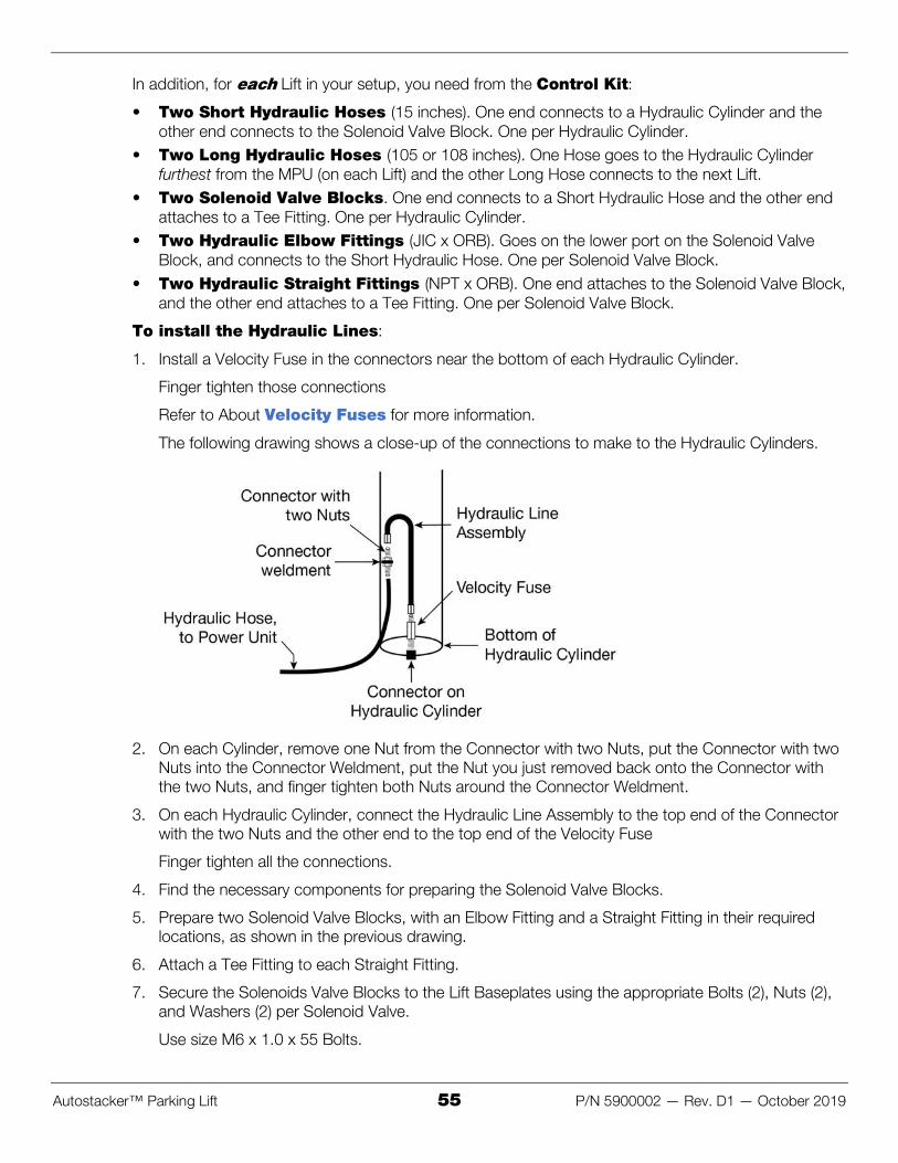
Autostacker™ Parking Lift 55 P/N 5900002 — Rev. D1 — October 2019
In addition, for each Lift in your setup, you need from the Control Kit:
• Two Short Hydraulic Hoses (15 inches). One end connects to a Hydraulic Cylinder and the other end connects to the Solenoid Valve Block. One per Hydraulic Cylinder.
• Two Long Hydraulic Hoses (105 or 108 inches). One Hose goes to the Hydraulic Cylinder furthest from the MPU (on each Lift) and the other Long Hose connects to the next Lift.
• Two Solenoid Valve Blocks. One end connects to a Short Hydraulic Hose and the other end attaches to a Tee Fitting. One per Hydraulic Cylinder.
• Two Hydraulic Elbow Fittings (JIC x ORB). Goes on the lower port on the Solenoid Valve Block, and connects to the Short Hydraulic Hose. One per Solenoid Valve Block.
• Two Hydraulic Straight Fittings (NPT x ORB). One end attaches to the Solenoid Valve Block, and the other end attaches to a Tee Fitting. One per Solenoid Valve Block.
To install the Hydraulic Lines:
1. Install a Velocity Fuse in the connectors near the bottom of each Hydraulic Cylinder.
Finger tighten those connections
Refer to About Velocity Fuses for more information.
The following drawing shows a close-up of the connections to make to the Hydraulic Cylinders.
2. On each Cylinder, remove one Nut from the Connector with two Nuts, put the Connector with two Nuts into the Connector Weldment, put the Nut you just removed back onto the Connector with the two Nuts, and finger tighten both Nuts around the Connector Weldment.
3. On each Hydraulic Cylinder, connect the Hydraulic Line Assembly to the top end of the Connector with the two Nuts and the other end to the top end of the Velocity Fuse
Finger tighten all the connections.
4. Find the necessary components for preparing the Solenoid Valve Blocks.
5. Prepare two Solenoid Valve Blocks, with an Elbow Fitting and a Straight Fitting in their required locations, as shown in the previous drawing.
6. Attach a Tee Fitting to each Straight Fitting.
7. Secure the Solenoids Valve Blocks to the Lift Baseplates using the appropriate Bolts (2), Nuts (2), and Washers (2) per Solenoid Valve.
Use size M6 x 1.0 x 55 Bolts.

Autostacker™ Parking Lift 56 P/N 5900002 — Rev. D1 — October 2019
8. Attach a Short Hydraulic Hose to each Hydraulic Line Assembly, then attach the other end of each Hose to the Elbow Fitting on the Solenoid Valve Blocks.
The Solenoid Valve Blocks are not labeled S1 through S4; they are only labeled here to distinguish between the various components.
The following drawing shows the hydraulic connections between two Autostackers.
9. Remove the Power Unit from its packaging, then place the Power Unit near the first Lift.
10. Attach an Elbow Fitting (-04 JIC x -06 ORB) from the MPU Plumbing Kit to each Hydraulic Out Port on the Power Unit.
11. Connect the two Steel Hydraulic Lines from the MPU Plumbing Kit to the Hydraulic Elbow Fittings you just connected to the Power Unit.
12. Find the Medium and Extra-Long Hydraulic Hose from the MPU Plumbing Kit and connect them to the Steel Hydraulic Lines using two Nipple Fittings.
13. Connect the other end of the Medium Hydraulic Hose to the Tee Fitting attached to S1.
14. Connect the other end of the Extra-Long Hydraulic Hose to the Tee Fitting attached to S2.
15. Take a Long Hydraulic Hose from the Control Kit and connect it to the unattached end of the Tee Fitting on S1.
16. Using the components from the Control Kit for the next Lift, prepare the next set of Hydraulic Cylinders.
Refer to steps 1-8 for additional instruction.
17. Using the same Long Hose attached to S1 on the first Lift, connect the other end to the Tee Fitting on S3 on the next Lift.
18. Connect the second Long Hydraulic Hose to the Tee Fitting on S2 on the first Lift, then connect the other end of the same Hose to the Tee Fitting connected to S4 on the next Lift.
19. If there are no further Lifts to connect to, secure the unattached ends of the Tee Fittings with a Cap Fitting, as shown in the following drawing.

Autostacker™ Parking Lift 57 P/N 5900002 — Rev. D1 — October 2019
The following drawing shows the connections to make to the last Tee Fittings.
Not drawn to scale. Some components are exaggerated or not shown for easier understanding.
20. If there are additional Lifts to connect the Hydraulic Hoses to, continue repeating steps 1 through 18 until you reach your ideal configuration, then complete step 19.
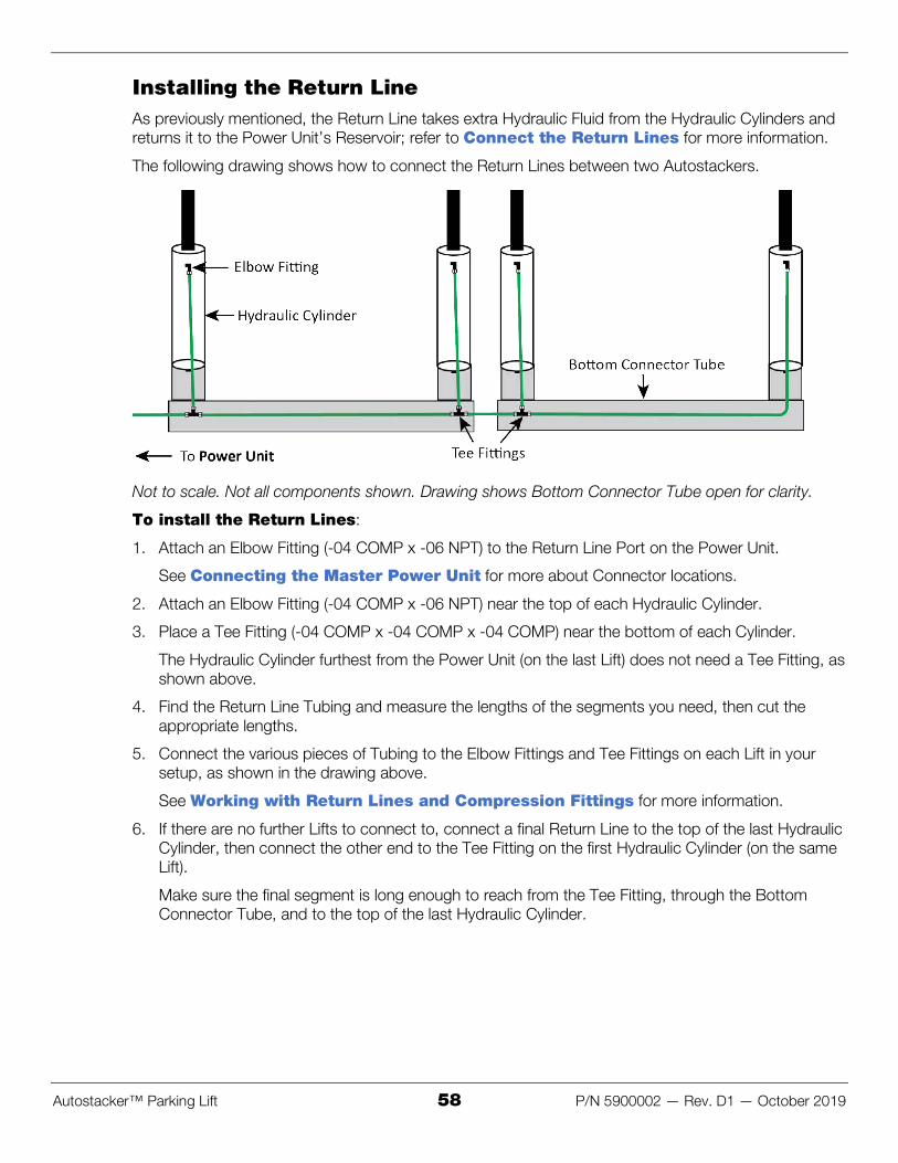
Autostacker™ Parking Lift 58 P/N 5900002 — Rev. D1 — October 2019
Installing the Return Line As previously mentioned, the Return Line takes extra Hydraulic Fluid from the Hydraulic Cylinders and returns it to the Power Unit’s Reservoir; refer to Connect the Return Lines for more information.
The following drawing shows how to connect the Return Lines between two Autostackers.
Not to scale. Not all components shown. Drawing shows Bottom Connector Tube open for clarity.
To install the Return Lines:
1. Attach an Elbow Fitting (-04 COMP x -06 NPT) to the Return Line Port on the Power Unit.
See Connecting the Master Power Unit for more about Connector locations.
2. Attach an Elbow Fitting (-04 COMP x -06 NPT) near the top of each Hydraulic Cylinder.
3. Place a Tee Fitting (-04 COMP x -04 COMP x -04 COMP) near the bottom of each Cylinder.
The Hydraulic Cylinder furthest from the Power Unit (on the last Lift) does not need a Tee Fitting, as shown above.
4. Find the Return Line Tubing and measure the lengths of the segments you need, then cut the appropriate lengths.
5. Connect the various pieces of Tubing to the Elbow Fittings and Tee Fittings on each Lift in your setup, as shown in the drawing above.
See Working with Return Lines and Compression Fittings for more information.
6. If there are no further Lifts to connect to, connect a final Return Line to the top of the last Hydraulic Cylinder, then connect the other end to the Tee Fitting on the first Hydraulic Cylinder (on the same Lift).
Make sure the final segment is long enough to reach from the Tee Fitting, through the Bottom Connector Tube, and to the top of the last Hydraulic Cylinder.

Autostacker™ Parking Lift 59 P/N 5900002 — Rev. D1 — October 2019
Attach the Conduit Tube In order to place the Control Stand at the Rear of the Lift, you need to first attach the Conduit Tube to the Bottom Connector Tube.
If you plan to position the Control Stand at the Front of the Lift, continue to the next section.
As mentioned in Positioning the Bottom Connector Tube, there is a Window on the Bottom Connector Tube used for routing the Control Stand wiring. The Conduit Tube protects the Control Stand wiring from being exposed and damaged.
The components involved include:
• Conduit Cover Plate. Attaches to the Window on the Bottom Connector Tube, facing the Rear of the Lift.
• Solid Cover Plate. Attaches to the Window on the Bottom Connector Tube, facing the Front of the Lift.
• Conduit Fitting. Attaches to the Conduit Cover Plate and holds one side of the Conduit Tube. • Conduit Tube. Attaches to the Conduit Fitting. Used for routed the Control Stand wiring.
The following drawing shows how to attach the Conduit Tube to the Bottom Connector Tube.
Not to scale. Not all components are shown. Side view.
To attach the Conduit Tube:
1. Find the Conduit Cover Plate, Solid Cover Plate, and the Conduit Fitting.
2. Attach the Conduit Fitting to the Conduit Cover Plate, then attach the Conduit Cover Plate to the Window on the Bottom Connector Tube.
Use two M6 x 1 x 10 Screws.
3. Attach the Solid Cover Plate to the Window on the Connector Tube facing to the front of the Lift.
Use two more M6 x 1 x 10 Screws.
4. Connect the Conduit Tube to the Conduit Fitting, then adjust the screw on the Fitting to hold the Tube securely in place.

Autostacker™ Parking Lift 60 P/N 5900002 — Rev. D1 — October 2019
Installing the Control Stands The Control Stand holds the Controls to operate a Lift in your setup; each Lift has its own Control Stand. The Control Stand can be placed at the Front or Rear of the Lift, although the installation for either orientation is different. Those procedures are described here.
Each Control Stand comes with a Placard containing operation instructions.
The following steps explain how to install, but not make the connections to, the Controls for each Lift. An Electrician is not needed to install the Controls, only to connect them to the Power Unit.
DANGER Do not connect the wires to the Power Unit at this point; that task is for an ؍Electrician. All wiring connections made to the Power Unit must be performed by a licensed, certified Electrician.
The following drawing shows the Control Stand at the Front of the Lift.
Not necessarily to scale. Not all components shown. Drawing shows the Stand at the Front of the Lift.
To install the Control Stand at the Front of the Lift:
1. Find the Control Box, Control Stand, and the three rolls of Electrical Cables from the Control Kit (14 AWG-4, 16 AWG-2, and 16 AWG-6).
2. By the Power Unit, route the 14-4 Cable through the Bottom Connector Tube.
Let the wires hang out of the Window you want to use.
3. Place the Control Stand nearby the selected Window, with the opening at the bottom of the Control Stand facing towards the Lift.
4. Remove the Screws from the Control Box to have access to the wiring inside.
5. Connect the 16-6 Cable to the Controls, then route the Cable through the Stand.
Refer to Wiring Diagrams for wiring information.
6. Connect the two Solenoids on each Lift together with the 16-2 Cable, then attach the 16-2 cable to the 16-6 Cable.
Refer to Wiring Diagrams for wiring information.

Autostacker™ Parking Lift 61 P/N 5900002 — Rev. D1 — October 2019
7. Connect the remaining 16-6 wires to the 14-4 wires coming out of the Bottom Connector Tube.
Refer to Wiring Diagrams for wiring information.
8. Attach the Control Box to the Stand using a Bolt, Washer, and Nut in each hole, placing the Safety Placard Bracket between the Control Stand Plate and a Washer.
Use size M6 X 1 X 25 Bolts.
Position the Control Box so that the Buzzer is facing down, to protect from the outdoor elements.
The following drawing shows how to orient the Placard Bracket on the Control Stand.
Not necessarily to scale. Not all components shown. Side view.
9. Attach the Key Ring and Safety Placard to the Bracket.
10. Connect the Control Stand to the Bottom Connector Tube using the supplied Bolts.

Autostacker™ Parking Lift 62 P/N 5900002 — Rev. D1 — October 2019
The following drawing shows the Control Stands at the Rear of the Lift.
To install the Control Stand at the Rear of the Lift:
1. Find the 14-4 Cable and route it through the Bottom Connector Tube to the Conduit Fitting.
2. Use the 16-2 Cable to connect the Solenoids near the bottom of each Hydraulic Cylinder (two per Lift).
Refer to Wiring Diagrams for wiring information.
3. Route the 16-6 Cable all the way through the Conduit Tube, then attach the wires to the wiring coming out of the Bottom Connector Tube.
Refer to Wiring Diagrams for wiring information.
4. Remove the Cover of the Control Box to have access to the wiring inside.
5. Find the Control Stand, then route the other end of the 16-6 wire through the opening in the Control Stand.
6. Connect the 16-6 wire to the Controls inside the Control Box.
Refer to Wiring Diagrams for wiring information.
DANGER Do not connect the wires to the Power Unit at this point; that task is for an ؍Electrician. All wiring connections made to the Power Unit must be performed by a licensed, certified Electrician.
7. Attach the Placard to the Control Stand, as described in the previous procedure.
8. Secure the Control Box to the Control Stand using a Screw, Washer, and Nut in each hole.
9. When you are ready to anchor the Control Stand, use the two holes on the Control Stand Base to mark the locations on the ground.

Autostacker™ Parking Lift 63 P/N 5900002 — Rev. D1 — October 2019
10. Move the Control Stand out of the way, then drill two holes 3/8" wide by 4" (102 mm) deep in the concrete floor at the locations you marked.
Go in straight; do not let the drill wobble. Use a carbide bit (conforming to the current ANSI B212.15).
11. Remove all dust from the holes.
12. Use a wire brush, vacuum, hand pump, or compressed air. Do not ream the hole. Do not make the hole any wider than the drill made it.
13. Move the Control Stand in place over the two holes, then insert an Anchor Bolt with a Washer into each hole, tapping it down into the hole.
14. Wrench the Anchor Bolt clockwise to the recommended installation torque, 85-95 pound feet, using a Torque Wrench.

Autostacker™ Parking Lift 64 P/N 5900002 — Rev. D1 — October 2019
Contacting the Electrician As mentioned previously, there are installation tasks that require a licensed, certified Electrician.
DANGER All wiring must be performed by a licensed, certified Electrician. If someone who is ؍not a certified Electrician attempts these tasks, they could damage the Lift or be electrocuted, resulting in serious injury or even death.
The Electrician needs to:
x Connect a power source to the Master Power Unit. A power source is required. The Power Unit comes with a pigtail for wiring to a power source. Have your Electrician connect a power cord with plug on the electrical box on the Lift (for connection to a power outlet) or have them wire it directly into the electrical system at the Lift location.
x Connect the Control Stands to the MPU. A power source is required.
x Install a Power Disconnect Switch. Ensures you can quickly and completely interrupt electrical power to the Lift in the event of an electrical circuit fault, emergency situation, or when equipment is undergoing service or maintenance.
x Install a Thermal Disconnect Switch. Optional. Ensures the equipment shuts down in the event of an overload or an overheated motor. Refer to Install a Thermal Disconnect Switch for more information. The motor on the Power Unit that comes with the Lift is not thermally protected.
The Electrician is responsible for providing:
x an appropriate plug to attach to the Power Unit x an appropriate Power Cord that goes from the power source to the plug on the Power Unit x a Thermal Disconnect Switch
Important electrical information:
– 220 VAC, 60 Hz, single phase, 5 HP requires a minimum 8 AWG wire
– 208-230 VAC, 50/60 Hz, three phase, 10 HP requires a minimum 8 AWG wire
– 460 VAC, 60 Hz, three phase, 10 HP requires a minimum 10 AWG wire
DANGER Risk of explosion: This equipment has internal arcing or parts that may spark and ؍should not be exposed to flammable vapors. The Power Unit’s motor should not be located in a recessed area or below floor level. Never expose the motor to rain or other damp environments; damage to the motor caused by water is not covered by the warranty.

Autostacker™ Parking Lift 65 P/N 5900002 — Rev. D1 — October 2019
Connecting the Master Power Unit The Power Unit for your Lift setup is either 220 VAC, 60Hz, 1Ph or 208-230/460 VAC, 50/60 Hz, 3 Ph. The Power Unit must be connected to an appropriate power source.
BendPak offers an optional MPU Enclosure that protects the Power Unit from the outdoor elements. Call (800) 253-2363 for more information.
.DANGER All wiring must be performed only by a licensed, certified Electrician ؍
Refer to Wiring Diagrams for wiring information.
.CAUTION The Power Unit’s Motor is not thermally protected ؍
The Master Power Unit has multiple connections:
• Two Hydraulic Lines and One Return Line. Already in place and connected. • Control Stand Cable. Connects the Control Stands to the power source. • Power Cable. Connects the Power Unit to the power source. • Power Source. A power source is needed to operate the Lifts.
CAUTION The Hydraulic Power Ports are almost always labeled P1/P2; the Hydraulic Return ؍Ports are commonly labeled T1/T2, CV1/CV2, or G. Do not accidentally attach a Hydraulic Hose to the Return Line Port. Your Autostacker will not work right unless the Hydraulic Hoses and the Return Line are attached to the correct connector.
The following drawing shows the connections to make to your Master Power Unit.
Drawing not to scale. Not all components shown. Drawing shows top view and side view of the same area. The Hydraulic Return Port is on the side of the Valve Block.
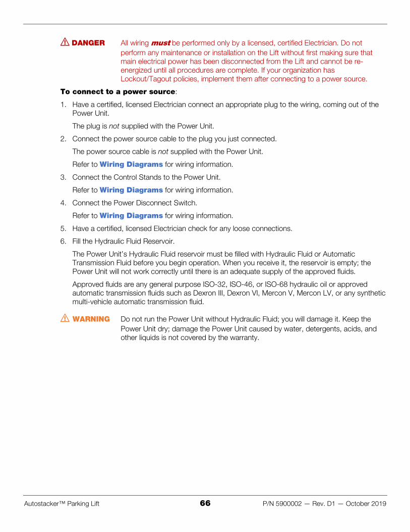
Autostacker™ Parking Lift 66 P/N 5900002 — Rev. D1 — October 2019
DANGER All wiring must be performed only by a licensed, certified Electrician. Do not ؍perform any maintenance or installation on the Lift without first making sure that main electrical power has been disconnected from the Lift and cannot be re-energized until all procedures are complete. If your organization has Lockout/Tagout policies, implement them after connecting to a power source.
To connect to a power source:
1. Have a certified, licensed Electrician connect an appropriate plug to the wiring, coming out of the Power Unit.
The plug is not supplied with the Power Unit.
2. Connect the power source cable to the plug you just connected.
The power source cable is not supplied with the Power Unit.
Refer to Wiring Diagrams for wiring information.
3. Connect the Control Stands to the Power Unit.
Refer to Wiring Diagrams for wiring information.
4. Connect the Power Disconnect Switch.
Refer to Wiring Diagrams for wiring information.
5. Have a certified, licensed Electrician check for any loose connections.
6. Fill the Hydraulic Fluid Reservoir.
The Power Unit’s Hydraulic Fluid reservoir must be filled with Hydraulic Fluid or Automatic Transmission Fluid before you begin operation. When you receive it, the reservoir is empty; the Power Unit will not work correctly until there is an adequate supply of the approved fluids.
Approved fluids are any general purpose ISO-32, ISO-46, or ISO-68 hydraulic oil or approved automatic transmission fluids such as Dexron III, Dexron VI, Mercon V, Mercon LV, or any synthetic multi-vehicle automatic transmission fluid.
WARNING Do not run the Power Unit without Hydraulic Fluid; you will damage it. Keep the ؍Power Unit dry; damage the Power Unit caused by water, detergents, acids, and other liquids is not covered by the warranty.

Autostacker™ Parking Lift 67 P/N 5900002 — Rev. D1 — October 2019
Operation Before operating an Autostacker in your Multi-Autostacker lineup, make sure to check the Lift and the surrounding area for safety. Refer to Preparing to Raise or Lower a Vehicle for a safety checklist and operation instructions.
The Controls Your Autostacker is operated via the Controls; the Controls used in your Multi-Lift setup are similar to the Controls used with a standard Autostacker. Refer to The Autostacker Console for more information.
WARNING Only one Autostacker can be raised or lowered at a time. Do not attempt to operate ؍more than one Lift at the same time; you will damage the Power Unit.
The following graphics show the Controls for a standard Autostacker and the Controls for each Lift in a Multi-Lift configuration.
The Controls for a single Autostacker:
The Controls for multiple Autostackers (one per Lift):

Autostacker™ Parking Lift 68 P/N 5900002 — Rev. D1 — October 2019
Wiring Diagrams

Autostacker™ Parking Lift 69 P/N 5900002 — Rev. D1 — October 2019
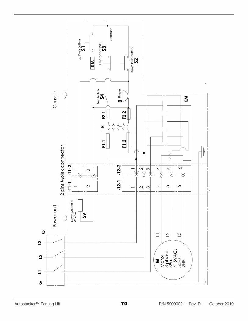
Autostacker™ Parking Lift 70 P/N 5900002 — Rev. D1 — October 2019

Autostacker™ Parking Lift 71 P/N 5900002 — Rev. D1 — October 2019
Multi-Autostacker Each Control Stand requires three Electrical Cables, of varying gauges:
• #14 AWG. Four wires; Green, Red, Black, and White. One end of the Cable goes to the Power Unit, and the other end goes through the Bottom Connector Tube, connecting to each Lift.
• #16 AWG. Two wires; Black and Blue. Interlinks the two Solenoids on each Lift, and connects to the Blue and Orange wire coming from the Control Stand.
• #16 AWG. Six wires; Green, Red, Black, White, Blue, and Orange. One end connects to the Control Box (on Control Stand), and the other end connects to the Cable that is routed through the Bottom Connector Tube.
The following graphic shows the various connections to make to your Electrical system.
Not drawn to scale. Some components are missing or exaggerated for easier understanding.

Autostacker™ Parking Lift 72 P/N 5900002 — Rev. D1 — October 2019

Autostacker™ Parking Lift 73 P/N 5900002 — Rev. D1 — October 2019

Autostacker™ Parking Lift 74 P/N 5900002 — Rev. D1 — October 2019
Labels

Autostacker™ Parking Lift 75 P/N 5900002 — Rev. D1 — October 2019

Autostacker™ Parking Lift 76 P/N 5900002 — Rev. D1 — October 2019

Autostacker™ Parking Lift 77 P/N 5900002 — Rev. D1 — October 2019

Autostacker™ Parking Lift 78 P/N 5900002 — Rev. D1 — October 2019

Autostacker™ Parking Lift 79 P/N 5900002 — Rev. D1 — October 2019

Autostacker™ Parking Lift 80 P/N 5900002 — Rev. D1 — October 2019
Parts Diagrams
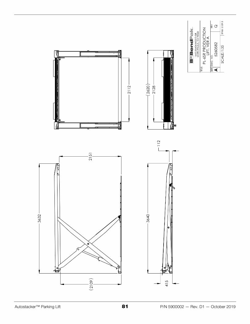
Autostacker™ Parking Lift 81 P/N 5900002 — Rev. D1 — October 2019

Autostacker™ Parking Lift 82 P/N 5900002 — Rev. D1 — October 2019

Autostacker™ Parking Lift 83 P/N 5900002 — Rev. D1 — October 2019

Autostacker™ Parking Lift 84 P/N 5900002 — Rev. D1 — October 2019

Autostacker™ Parking Lift 85 P/N 5900002 — Rev. D1 — October 2019

Autostacker™ Parking Lift 86 P/N 5900002 — Rev. D1 — October 2019

Autostacker™ Parking Lift 87 P/N 5900002 — Rev. D1 — October 2019

Autostacker™ Parking Lift 88 P/N 5900002 — Rev. D1 — October 2019

Autostacker™ Parking Lift 89 P/N 5900002 — Rev. D1 — October 2019

Autostacker™ Parking Lift 90 P/N 5900002 — Rev. D1 — October 2019

Autostacker™ Parking Lift 91 P/N 5900002 — Rev. D1 — October 2019

Autostacker™ Parking Lift 92 P/N 5900002 — Rev. D1 — October 2019

Autostacker™ Parking Lift 93 P/N 5900002 — Rev. D1 — October 2019

Autostacker™ Parking Lift 94 P/N 5900002 — Rev. D1 — October 2019

Autostacker™ Parking Lift 95 P/N 5900002 — Rev. D1 — October 2019

Autostacker™ Parking Lift 96 P/N 5900002 — Rev. D1 — October 2019

Autostacker™ Parking Lift 97 P/N 5900002 — Rev. D1 — October 2019

Autostacker™ Parking Lift 98 P/N 5900002 — Rev. D1 — October 2019

Autostacker™ Parking Lift 99 P/N 5900002 — Rev. D1 — October 2019

Autostacker™ Parking Lift 100 P/N 5900002 — Rev. D1 — October 2019

Autostacker™ Parking Lift 101 P/N 5900002 — Rev. D1 — October 2019

Autostacker™ Parking Lift 102 P/N 5900002 — Rev. D1 — October 2019

Autostacker™ Parking Lift 103 P/N 5900002 — Rev. D1 — October 2019

1645 Lemonwood Drive
Santa Paula, CA 93060 USA © 2019 BendPak Inc. All rights reserved. bendpak.com