Embed Size (px)
Citation preview

INS_CLFE4+1SMS[POE](C,U)_REV– 10/27/11 PAGE 1TECH SUPPORT: 1.888.678.9427
INSTALLATION AND OPERATION MANUAL
CLFE4+1SMS[POE](C,U) Series 10/100 4TX+1EX ETHERNET SELF-MANAGED SWITCH WITH POWER OVER ETHERNET (POE+)
The ComNet CopperLine® CLFE4+1SMS[POE](C,U) is a five-port Ethernet switch with uplink management functionality and provides 4 copper ports operating at 10/100Mbps and is designed to combine four electrical ports into a single electrical Cat5, UTP or Coax CopperLine port that forwards this data to the next network device. There is no programming required to use this product. The ComNet CLFE4+1SMS comes pre-programmed, preventing network video flooding with DIP switch selection of the fifth electrical port as uplink or as an unmanaged switch. Ports 1–4 of the CLFE4+1SMSPOE can supply up to thirty (30) watts of Power over Ethernet (PoE) and incorporate PoE+ features based on the IEEE 802.3at standard. It is “Plug-and-Play”.
Bi-color (Red/Green) LED indicators are provided for rapidly ascertaining equipment operating status. Table 2 on Page 7 describes the LED indicators for each light on the unit.
These units are interchangeable between stand-alone or card mount configurations, or may be DIN-rail mounted by the addition of ComNet model DINBKT1 or DINBKT4 adaptor plate. See Figure A on Page 10 for mounting instructions.
This manual serves the following ComNet Model Numbers:
CLFE4+1SMSC
CLFE4+1SMSU
CLFE4+1SMSPOEC
CLFE4+1SMSPOEU

INS_CLFE4+1SMS[POE](C,U)_REV– 10/27/11 PAGE 2
INSTALLATION AND OPERATION MANUAL CLFE4+1SMS[POE](C,U) SERIES
TECH SUPPORT: 1.888.678.9427
FIGURE 1 – CLFE4+1SMSPOEC FOUR CHANNEL SURFACE OR RACK MOUNT COAX UNIT WITH POE
FIGURE 2 – CLFE4+1SMSPOEC FOUR CHANNEL SURFACE OR RACK MOUNT COAX UNIT WITH POE
EXTENDED DISTANCE
PORT 4 ETHERNET
PORT 3ETHERNET
PORT 2ETHERNET
PORT 1 ETHERNET
Operating Power: 9 to 12 VDC (non-PoE), 48 to 56VDC (PoE)Power Consumption: 10W (non-PoE), 130W (Max PoE)
Black (GND) Black w/ White Stripe (+Vin)
POE–POE+
10/100 data rate DIP switchLocal/Remote DIP switchManaged/Unmanaged DIP switchSee Installation Instructions
CLFE4+1SMSPOEC Front Panel CLFE4+1SMSPOEC Rear Panel
Do not use for POE Applications.

INS_CLFE4+1SMS[POE](C,U)_REV– 10/27/11 PAGE 3
INSTALLATION AND OPERATION MANUAL CLFE4+1SMS[POE](C,U) SERIES
TECH SUPPORT: 1.888.678.9427
EXTENDED DISTANCE
PORT 4 ETHERNET
PORT 3 ETHERNET
PORT 2 ETHERNET
PORT 1 ETHERNET
FIGURE 3 – CLFE4+1SMSPOEU FOUR CHANNEL SURFACE OR RACK MOUNT UTP UNIT WITH POE
FIGURE 4 – CLFE4+1SMSPOEU FOUR CHANNEL SURFACE OR RACK MOUNT UTP UNIT WITH POE
Operating Power: 9 to 12 VDC (non-PoE), 48 to 56VDC (PoE)Power Consumption: 10W (non-PoE), 130W (Max PoE)
Black (GND) Black w/ White Stripe (+Vin)
Do not use for POE Applications.
POE–POE+
10/100 data rate DIP switchLocal/Remote DIP switchManaged/Unmanaged DIP switch1 Pair/4 Pair DIP switchSee Installation Instructions
CLFE4+1SMSPOEU Front Panel CLFE4+1SMSPOEU Rear Panel

INS_CLFE4+1SMS[POE](C,U)_REV– 10/27/11 PAGE 4
INSTALLATION AND OPERATION MANUAL CLFE4+1SMS[POE](C,U) SERIES
TECH SUPPORT: 1.888.678.9427
FIGURE 5 – CLFE4+1SMSC FOUR CHANNEL SURFACE OR RACK MOUNT COAX UNIT
FIGURE 6 – CLFE4+1SMSC FOUR CHANNEL SURFACE OR RACK MOUNT COAX UNIT
EXTENDED DISTANCE
PORT 4 ETHERNET
PORT 3 ETHERNET
PORT 2ETHERNET
PORT 1 ETHERNET
Operating Power: 9 to 15 VDCPower Consumption: 10W
Black (GND) Black w/ White Stripe (+Vin)
CLFE4+1SMSC Front Panel CLFE4+1SMSC Rear Panel
10/100 data rate DIP switchLocal/Remote DIP switchManaged/Unmanaged DIP switchSee Installation Instructions

INS_CLFE4+1SMS[POE](C,U)_REV– 10/27/11 PAGE 5
INSTALLATION AND OPERATION MANUAL CLFE4+1SMS[POE](C,U) SERIES
TECH SUPPORT: 1.888.678.9427
EXTENDED DISTANCE
PORT 4 ETHERNET
PORT 3 ETHERNET
PORT 2ETHERNET
PORT 1 ETHERNET
FIGURE 7 – CLFE4+1SMSU FOUR CHANNEL SURFACE OR RACK MOUNT COAX UNIT
FIGURE 8 – CLFE4+1SMSU FOUR CHANNEL SURFACE OR RACK MOUNT UTP UNIT
Operating Power: 9 to 15 VDCPower Consumption: 10W
Black (GND) Black w/ White Stripe (+Vin)
CLFE4+1SMSU Front Panel CLFE4+1SMSU Rear Panel
10/100 data rate DIP switchLocal/Remote DIP switchManaged/Unmanaged DIP switch1 Pair/4 Pair DIP switchSee Installation Instructions

INS_CLFE4+1SMS[POE](C,U)_REV– 10/27/11 PAGE 6
INSTALLATION AND OPERATION MANUAL CLFE4+1SMS[POE](C,U) SERIES
TECH SUPPORT: 1.888.678.9427
IMPORTANT NOTE. PLEASE READ. The applications are shown as general representations only and are not intended to show detailed network topologies. Your actual network will differ, requiring changes or perhaps additional network equipment to accommodate the systems as illustrated. Please contact ComNet’s Design Center to discuss your specific requirements.
Ethernet Connection
PoE PowerExtended Connection
PoE Camera
PoE Camera
PoE Camera
PoE Camera
Ethernet Switch
Local Remote
CLFE1EO(C,U) CLFE4+1SMSPOE(C,U)
Power
48V to 56V
Power
IP Camera
Power
IP Camera
Power
IP Camera
Power
IP Camera
Ethernet Switch
Local Remote
CLFE1EO(C,U)
CLFE4+1SMS(C,U)Power
9V to 15V
APPLICATION DIAGRAMNote: Coaxial applications use the CLFE4+1SMS[POE]C and CLFE1EOC; UTP applications use the CLFE4+1SMS[POE]U and CLFE1EOU.
Remote PoE Injection Mode
Non-PoE Mode

INS_CLFE4+1SMS[POE](C,U)_REV– 10/27/11 PAGE 7
INSTALLATION AND OPERATION MANUAL CLFE4+1SMS[POE](C,U) SERIES
TECH SUPPORT: 1.888.678.9427
INSTALLATION INSTRUCTIONS1 - SET DATA RATE DIP SWITCHES
Locate the 10/100 data rate DIP switch on the unit. Set the data rate according to bandwidth required. The default setting for the data rate DIP switch is 100Mbps.NOTE: The data rate must be set the same on both the local and remote units.
2 - SET WIRE PAIR DIP SWITCHES (UTP MODELS ONLY, FOR COAX MODELS SKIP TO STEP 3)Locate the wire pair DIP switch on the unit. Set the pair according to number of twisted wire pairs used (1 or 4). The default setting for the wire pair DIP switch is 4 pair.NOTE: The number of pairs selected must be set the same on both the local and remote units.
3 - SET LOCAL/REMOTE DIP SWITCHESSet the Local/Remote switch to Local (L) for Local (head end) devices or Remote (R) for Remote (field end) devices. The default setting for this switch is Remote.
4 - SET MANAGED/UNMANAGED DIP SWITCHESSet the Managed/Unmanaged switch to the “Managed” position. The default setting for this switch is Managed.NOTE: In most cases, you will want to set the unit to “Managed” to prevent port flooding.
5 - CONNECT EXTENDED WIRINGConnect Extended Distance Port to field wiring.
6 - CONNECT NETWORK WIRINGUsing CAT5/5e, connect Local unit to network and Remote unit to camera.
7 - CONNECT POWERConnect power to unit per the following table:
Table 1 – Power Connections per Use Case Non-PoE PoE
Operating Voltage 9 to 15 VDC (9 VDC † when in C1 or C2)† 48 to 56 VDC
Use Power Connectors GND and +Vin POE+ and POE-
Note: For the PoE models only use the PoE power connectors.
† Contact the ComNet Design Center, or refer to the appropriate installation and operation manual when configuring and specifying power for a deployment.
8 - VERIFY FUNCTIONALITYSee LED table below and Troubleshooting Guide if corrective action is needed.
Table 2 – Indicating LEDsPWR POE Link (Ethernet Port) Activity (Ethernet Port) EXT LNK
GREEN Power Applied PoE Applied – – 10M or 100M Link DetectedYELLOW – – Link Detected – –OFF Power Off No PoE Present No Link – No LinkBLINK – – – Data Activity Data Activity
For 1-pair mode, use the first pair of pins (pins 1 and 2) of the “Extended Ethernet” RJ-45 port.
INS_CLFE4+1SMS[POE](C,U)_REV– 10/27/11 PAGE 8
INSTALLATION AND OPERATION MANUAL CLFE4+1SMS[POE](C,U) SERIES
TECH SUPPORT: 1.888.678.9427
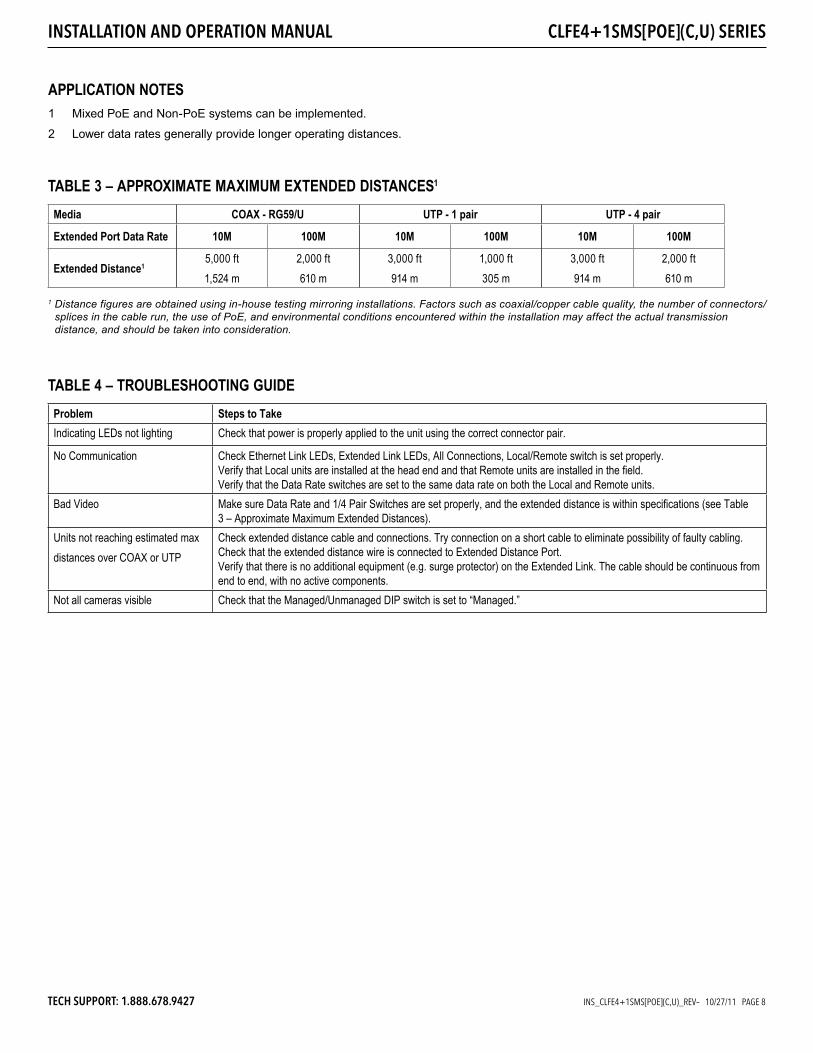
TABLE 4 – TROUBLESHOOTING GUIDEProblem Steps to TakeIndicating LEDs not lighting Check that power is properly applied to the unit using the correct connector pair.
No Communication Check Ethernet Link LEDs, Extended Link LEDs, All Connections, Local/Remote switch is set properly. Verify that Local units are installed at the head end and that Remote units are installed in the field.Verify that the Data Rate switches are set to the same data rate on both the Local and Remote units.
Bad Video Make sure Data Rate and 1/4 Pair Switches are set properly, and the extended distance is within specifications (see Table 3 – Approximate Maximum Extended Distances).
Units not reaching estimated max distances over COAX or UTP
Check extended distance cable and connections. Try connection on a short cable to eliminate possibility of faulty cabling.Check that the extended distance wire is connected to Extended Distance Port.Verify that there is no additional equipment (e.g. surge protector) on the Extended Link. The cable should be continuous from end to end, with no active components.
Not all cameras visible Check that the Managed/Unmanaged DIP switch is set to “Managed.”
TABLE 3 – APPROXIMATE MAXIMUM EXTENDED DISTANCES1
Media COAX - RG59/U UTP - 1 pair UTP - 4 pair
Extended Port Data Rate 10M 100M 10M 100M 10M 100M
Extended Distance15,000 ft 1,524 m
2,000 ft 610 m
3,000 ft 914 m
1,000 ft 305 m
3,000 ft 914 m
2,000 ft 610 m
1 Distance figures are obtained using in-house testing mirroring installations. Factors such as coaxial/copper cable quality, the number of connectors/splices in the cable run, the use of PoE, and environmental conditions encountered within the installation may affect the actual transmission distance, and should be taken into consideration.
1 Mixed PoE and Non-PoE systems can be implemented.
2 Lower data rates generally provide longer operating distances.
APPLICATION NOTES

INS_CLFE4+1SMS[POE](C,U)_REV– 10/27/11 PAGE 9
INSTALLATION AND OPERATION MANUAL CLFE4+1SMS[POE](C,U) SERIES
TECH SUPPORT: 1.888.678.9427
Recommended part is Wurth Part 742 711 32 S (Not included). Equivalent parts may be substituted.
LOOPING THE POWER CABLE AROUND THE FERRITE CORE
Attaching the ferrite core to the power cord of the unit helps prevent RF interference from radio signals.
1. Pull the fixing tab of the ferrite core to open it.
2. Make three loops around the core with the power cable of the unit.
3. Attach the ferrite core to the unit power cord as shown and press it until it clicks.
Lift up to release the lock and open the core.
Closed Open
Make three loops around the core with the power cable.
Start winding 5 to 10 cm (2 to 3.9 in) away from the power connection.
Close the lock. You may now operate the unit according to instructions.
ATTACHING THE FERRITE CORE TO THE POWER CORD OF THE UNIT (Ferrite core not included, must be purchased separately) When using v48VDC Power Supplies

INS_CLFE4+1SMS[POE](C,U)_REV– 10/27/11 PAGE 10
INSTALLATION AND OPERATION MANUAL CLFE4+1SMS[POE](C,U) SERIES
FIGURE ADimensions are for a ComFit module
8.38cm[3.3in]
2.7cm[1.06in]
4.19cm[1.65in]
0.8cm[0.31in]
0.4cm[0.16in]
0.62cm[0.24in]
6.37cm[2.50in]
13.2cm[5.2in]
11.9cm[4.7in]
15cm[5.9in]
7.5cm[2.9in]0.63cm
[0.25in]
2.75cm[1.1in]
44.45cm[17.50in]
48.26cm[19.0in]
15.44cm[6.08in]
1.9cm[0.75in]
4.37cm[1.72in]
1.9cm[0.75in]
INSTALLATION CONSIDERATIONS These units are supplied as Standalone/Rack mounted module. Units should be installed in dry locations protected from extremes of temperature and humidity.
WARNING: Unit is to be used with a Listed Class 2 power supply. Although the units may be mounted inside a ComNet rack the PoE models cannot be powered from the built-in rack PSU; they must be powered by an external 48-56VDC PSU.
IMPORTANT SAFEGUARDS: A) Elevated Operating Ambient - If installed in a closed or multi-unit rack
assembly, the operating ambient temperature of the rack environment may be greater than room ambient. Therefore, consideration should be given to installing the equipment in an environment compatible with the maximum ambient temperature (Tma) specified by the manufacturer.
B) Reduced Air Flow - Installation of the equipment in a rack should be such that the amount of air flow required for safe operation of the equipment is not compromised.
© 2016 Communication Networks. All Rights Reserved. “ComNet,” the “ComNet Logo,” “CopperLine,” and the “CopperLine Logo” are registered trademarks of Communication Networks.
3 CORPORATE DRIVE | DANBURY, CONNECTICUT 06810 | USA | T: 203.796.5300 | F: 203.796.5303 | TECH SUPPORT: 1.888.678.9427 | [email protected]
8 TURNBERRY PARK ROAD | GILDERSOME | MORLEY | LEEDS, UK LS27 7LE | T: +44 (0)113 307 6400 | F: +44 (0)113 253 7462 | [email protected]