Embed Size (px)
Citation preview
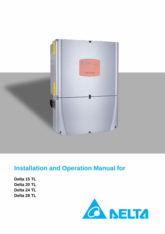
Installation and Operation Manual for
Delta 15 TL
Delta 20 TL
Delta 24 TL
Delta 28 TL
1
Contents
1. General information .................................................................................. 3
1.1 Intend of use .............................................................................. 3
1.2 System ........................................................................................ 3
2. Safety instructions .................................................................................... 3
2.1 Safety and Advisory Symbols ..................................................... 4
2.2 Inverter safety Labels ................................................................. 5
2.3 Safety Instructions...................................................................... 5
3. Product information .................................................................................. 6
3.1 Technical structure of the solar inverter .................................... 6
3.2 Inverter Type Labels ................................................................... 7
3.3 Equipment overview .................................................................. 9
3.4 Technical data .......................................................................... 11
3.5 Transport and storage .............................................................. 13
3.6 Certificate ................................................................................. 13
3.7 Warranty .................................................................................. 14
4. Installation .............................................................................................. 14
4.1 Visual inspection ...................................................................... 14
4.2 Installation location .................................................................. 14
4.3 Mounting the inverter .............................................................. 15
5. Electrical connection and wiring ............................................................. 20
5.1 General safety and information ............................................... 20
5.2 Opening the wiring box cover and conduit plugs .................... 20
5.3 Input connection to the PV array (DC side) ............................. 21
5.4 Selecting PV string fuse(s) ........................................................ 23
5.5 Output connection to grid (AC side) ........................................ 23
5.6 Grounding electrode conductor (GET) ..................................... 27
5.7 Connecting Communications Cables ........................................ 27
2
5.8 Multiple inverters ..................................................................... 28
5.9 Required screw torques ........................................................... 29
6. Commissioning ........................................................................................ 29
6.1 Status LEDs ............................................................................... 29
6.2 Inverter turn-on procedure ...................................................... 29
6.3 Inverter turn-off procedure ..................................................... 30
6.4 Settings ..................................................................................... 30
7. Diagnosis and Maintenance .................................................................... 30
7.1 Scheduled maintenance ........................................................... 30
7.2 Troubleshooting ....................................................................... 31
7.3 Disassembling and packing ...................................................... 31
8. Glossary ................................................................................................... 32
3
IMPORTANT SAFETY INSTRUCTIONS
SAVE THESE INSTRUCTIONS
1. General information
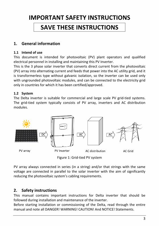
1.1 Intend of use This document is intended for photovoltaic (PV) plant operators and qualified electrical personnel in installing and maintaining this PV Inverter. This is the 3 phase solar inverter that converts direct current from the photovoltaic (PV) array into alternating current and feeds that power into the AC utility grid, and it is transformerless type without galvanic isolation, so the inverter can be used only with ungrounded photovoltaic modules, and can be connected to the electricity grid only in countries for which it has been certified/approved.
1.2 System The Delta inverter is suitable for commercial and large scale PV grid-tied systems. The grid-tied system typically consists of PV array, inverters and AC distribution modules.
Figure 1: Grid-tied PV system
PV array always connected in series (in a string) and/or that strings with the same voltage are connected in parallel to the solar inverter with the aim of significantly reducing the photovoltaic system’s cabling requirements.
2. Safety instructions This manual contains important instructions for Delta inverter that should be followed during installation and maintenance of the inverter. Before starting installation or commissioning of the Delta, read through the entire manual and note all DANGER! WARNING! CAUTION! And NOTICE! Statements.
4
All US electrical installations must comply and be in accordance with all the state, local, utility regulations, and National Electrical Code ANSI/NFPA 70. For installations in Canada, please ensure these are done in accordance with applicable Canadian standards.
2.1 Safety and Advisory Symbols
DANGER DANGER indicates a hazardous situation which, if not avoided, will result in death or serious injury.
WARNING WARNING indicates a hazardous situation which, if not avoided, could result in death or serious injury.
CAUTION CAUTION indicates a hazardous situation which, if not avoided, could result in minor or moderate injury.
NOTICE NOTICE indicates a situation that can result in property damage if not avoided.
HIGH VOLTAGE WARNING! Indicates hazardous high voltages are present, which, if not avoided, will result in death or serious injury. Thus, only authorized and trained personnel should install and/or maintain this product.
Hot surface
Equipment grounding conductor
Wait for a prescribed amount of time before engaging in the indicated action.
5
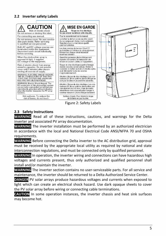
2.2 Inverter safety Labels
Figure 2: Safety Labels
2.3 Safety Instructions WARNING Read all of these instructions, cautions, and warnings for the Delta inverter and associated PV array documentation. WARNING The inverter installation must be performed by an authorized electrician in accordance with the local and National Electrical Code ANSI/NFPA 70 and OSHA requirements. WARNING Before connecting the Delta inverter to the AC distribution grid, approval must be received by the appropriate local utility as required by national and state interconnection regulations, and must be connected only by qualified personnel. WARNING In operation, the inverter wiring and connections can have hazardous high voltages and currents present, thus only authorized and qualified personnel shall install and/or maintain the inverter. WARNING The inverter section contains no user-serviceable parts. For all service and maintenance, the inverter should be returned to a Delta Authorized Service Center. DANGER PV solar arrays produce hazardous voltages and currents when exposed to light which can create an electrical shock hazard. Use dark opaque sheets to cover the PV solar array before wiring or connecting cable terminations. CAUTION In some operation instances, the inverter chassis and heat sink surfaces may become hot.
6
3. Product information
3.1 Technical structure of the solar inverter
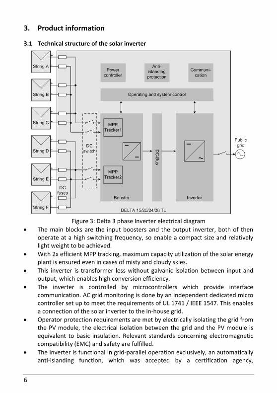
Figure 3: Delta 3 phase Inverter electrical diagram
The main blocks are the input boosters and the output inverter, both of then operate at a high switching frequency, so enable a compact size and relatively light weight to be achieved.
With 2x efficient MPP tracking, maximum capacity utilization of the solar energy plant is ensured even in cases of misty and cloudy skies.
This inverter is transformer less without galvanic isolation between input and output, which enables high conversion efficiency.
The inverter is controlled by microcontrollers which provide interface communication. AC grid monitoring is done by an independent dedicated micro controller set up to meet the requirements of UL 1741 / IEEE 1547. This enables a connection of the solar inverter to the in-house grid.
Operator protection requirements are met by electrically isolating the grid from the PV module, the electrical isolation between the grid and the PV module is equivalent to basic insulation. Relevant standards concerning electromagnetic compatibility (EMC) and safety are fulfilled.
The inverter is functional in grid-parallel operation exclusively, an automatically anti-islanding function, which was accepted by a certification agency,
7
guarantees secure disconnection in case of circuit isolation or interruptions in power supply and avoid isolated operation.
The DC arc-fault circuit interrupt (AFCI) is integrated, complies the requirement as Type 1 device in UL1699B standard, series arc faults can be detected.
The inverter is designed for indoor and outdoor application, the high-quality aluminum die-casting case corresponds to protection degree NEMA 4 / IP65 (water-jet proof and dust-proof) and is protected by an anti-corrosion finish.
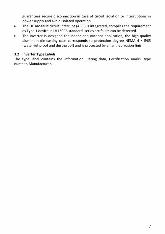
3.2 Inverter Type Labels The type label contains the information: Rating data, Certification marks, type number, Manufacturer.
8
Figure 4: Inverter type labels
9
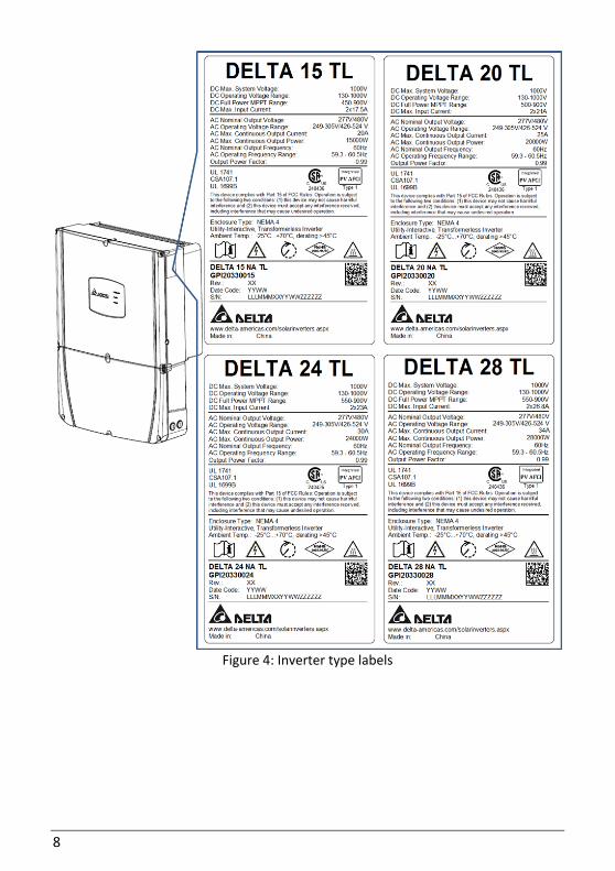
3.3 Equipment overview
Figure 5: Exterior view of inverter
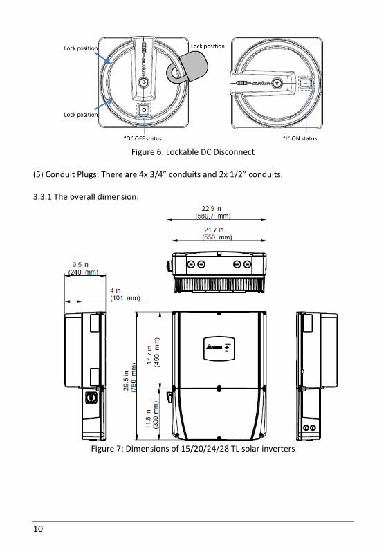
Description of the equipment features: (1) LED indicator lights: Indicate the status of inverter (2) Inverter Main box: This section is sealed at the factory and there are no user-serviceable parts inside. (3) Wiring box: The compartment where all the wiring for the inverter are done. (4) Lockable DC Disconnect: The DC disconnect is lockable and allows for the DC power to be switched off, the symbols "I" and "O" in the indication window represent the "On" and "Off" position of the switch.
10
Figure 6: Lockable DC Disconnect
(5) Conduit Plugs: There are 4x 3/4” conduits and 2x 1/2” conduits. 3.3.1 The overall dimension:
Figure 7: Dimensions of 15/20/24/28 TL solar inverters
11
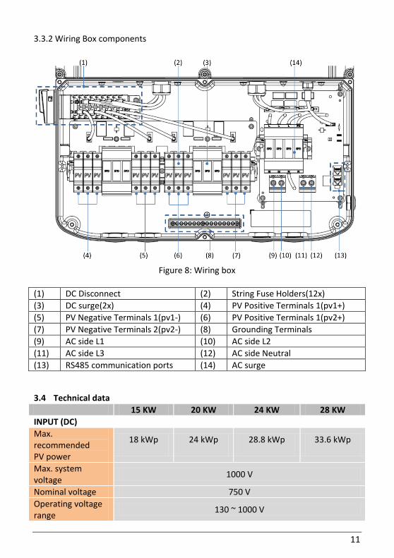
3.3.2 Wiring Box components
Figure 8: Wiring box
(1) DC Disconnect (2) String Fuse Holders(12x)
(3) DC surge(2x) (4) PV Positive Terminals 1(pv1+)
(5) PV Negative Terminals 1(pv1-) (6) PV Positive Terminals 1(pv2+)
(7) PV Negative Terminals 2(pv2-) (8) Grounding Terminals
(9) AC side L1 (10) AC side L2
(11) AC side L3 (12) AC side Neutral
(13) RS485 communication ports (14) AC surge
3.4 Technical data
15 KW 20 KW 24 KW 28 KW
INPUT (DC)
Max. recommended PV power
18 kWp 24 kWp 28.8 kWp 33.6 kWp
Max. system voltage
1000 V
Nominal voltage 750 V
Operating voltage range
130 ~ 1000 V
12
15 KW 20 KW 24 KW 28 KW
Full power MPP range
450 ~ 900 V 500 ~ 900 V 550 ~ 900 V
Max. input current 18.5 A per
MPP tracker 22 A per
MPP tracker 24.2 A per
MPP tracker 28.3 A per
MPP tracker
Max. short circuit current
23 A 27 A 29 A 34 A
Max. allowed imbalance power
10.8 kW 14.6 kW 17.1 kW 20 kW
DC disconnect Internal
MPP tracker 2
MPP efficiency >99.9%(Static), >99.6%(Dynamic)
Max. strings 6
DC Surge Arrestor SPD II optional
OUTPUT (AC)
Nominal power 15kW 20kW 24kW 28kW
Max. continuous output power
15 kW 20 kW 24 KW 28 KW
Nominal voltage 277/480 V
Operating voltage range
-12%/+10%
Nominal current 20.0 A 25.0 A 30.0 A 34.0 A
Max. continuous output current
20.0 A 26.0 A 30.0 A 34.0 A
Max. output overcurrent protection
40 A 40 A 50 A 50 A
Nominal frequency 60 Hz
Operating frequency range
59.3-60.5 Hz
Night consumption < 1.5 W
Total harmonic distortion @nominal power
< 3%
Power factor@ nominal power
> 0.99
Reactive Capacity 0.8 c ~ 0.8 i
AC Surge Arrestor SPC III optional
Communication
Communication Interface
RS485, Bluetooth
13
GENERAL SPECIFICATION
15 KW 20 KW 24 KW 28 KW
Max. efficiency 98.5% 99%
CEC efficiency 98.0 % 98.5 %
Operating temperature
-40 ~ 158°F (-40 ~ 70°C) | Derating above 113°F (45°C)
Storage temperature
-40 ~ 185°F (-40 ~ 85°C)
Humidity 0 ~ 100%
Max. operating altitude
2000m above sea level
MECHANICAL DESIGN
Dimensions L x W x D inches (L x W x D) mm
29.5 x 21.7 x 9.5 in (750 x 550 x 240 mm)
Weight 110 lbs (49.5 kg)
Cooling Natural Convection Internal Fan
AC connectors Screw terminals
DC connectors Screw terminals
Enclosure material Aluminum alloy
3.5 Transport and storage Always transport and store the solar power inverter in the original packaging or packaging of the same quality, observe the specifications relating to storage conditions (Temperature and humidity) described in “Technical data”. NOTICE A maximum of 5 inverters can be stacked.
3.6 Certificate Please check our web site at: http://www.delta-americas.com/SolarInverters.aspx for the most recent certificates.
Item STANDARDS / DIRECTIVES
Enclosure Protection Rating NEMA 4X, IEC 60068-2-11 (Salt mist)
Safety UL 1741, CSA 22.2 No. 107-01
SW Approval UL 1998
Isolation Monitor Interrupt (IMI) NEC 2014 article 690.35, UL1741 CRD
Anti-islanding protection IEEE 1547, IEEE 1547.1
EMC FCC part 15 Class B, ICES-003
AFCI UL1699B (Type 1), NEC 2014 690.11
14
3.7 Warranty The Delta 15KW/20KW/24KW/28KW 3-phase grid-tied inverter includes a standard 10-year warranty in effect from the time your inverter is commissioned. For the return procedures, please refer to our web site at http://www.delta-americas.com/SolarInverters.aspx for further information. For assistance with warranty repairs or returns you may contact our North America support hotline at: 1-877-442-4832 or via email at [email protected].
4. Installation
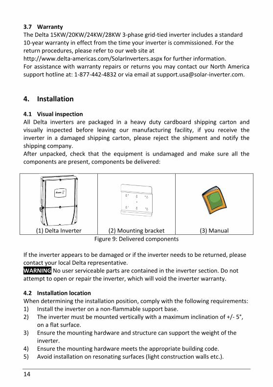
4.1 Visual inspection All Delta inverters are packaged in a heavy duty cardboard shipping carton and visually inspected before leaving our manufacturing facility, if you receive the inverter in a damaged shipping carton, please reject the shipment and notify the shipping company. After unpacked, check that the equipment is undamaged and make sure all the components are present, components be delivered:
(1) Delta Inverter (2) Mounting bracket (3) Manual
Figure 9: Delivered components
If the inverter appears to be damaged or if the inverter needs to be returned, please contact your local Delta representative. WARNING No user serviceable parts are contained in the inverter section. Do not attempt to open or repair the inverter, which will void the inverter warranty.
4.2 Installation location When determining the installation position, comply with the following requirements: 1) Install the inverter on a non-flammable support base. 2) The inverter must be mounted vertically with a maximum inclination of +/- 5°,
on a flat surface. 3) Ensure the mounting hardware and structure can support the weight of the
inverter. 4) Ensure the mounting hardware meets the appropriate building code. 5) Avoid installation on resonating surfaces (light construction walls etc.).
15
6) Choose inverter ambient temperature within -40°F to +113°F (-40°C to +45°C) for optimal efficiency of the PV system.
7) Avoid installation location where exceed the temperature limits specified in the inverter data sheet or overheat inverter, which will cause power limitation and efficiency drop.
8) Chose a mounting height for easy viewing of the display. 9) Despite having a NEMA 4x/ IP65 enclosure, the inverter must not be exposed to
heavy soiling. 10) The inverter should be installed in well ventilated environment to ensure good
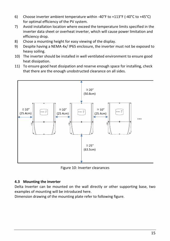
heat dissipation. 11) To ensure good heat dissipation and reserve enough space for installing, check
that there are the enough unobstructed clearance on all sides.
Figure 10: Inverter clearances
4.3 Mounting the inverter Delta Inverter can be mounted on the wall directly or other supporting base, two examples of mounting will be introduced here. Dimension drawing of the mounting plate refer to following figure.
16
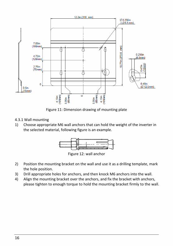
Figure 11: Dimension drawing of mounting plate
4.3.1 Wall mounting 1) Choose appropriate M6 wall anchors that can hold the weight of the inverter in
the selected material, following figure is an example.
Figure 12: wall anchor
2) Position the mounting bracket on the wall and use it as a drilling template, mark
the hole position. 3) Drill appropriate holes for anchors, and then knock M6 anchors into the wall. 4) Align the mounting bracket over the anchors, and fix the bracket with anchors,
please tighten to enough torque to hold the mounting bracket firmly to the wall.
17
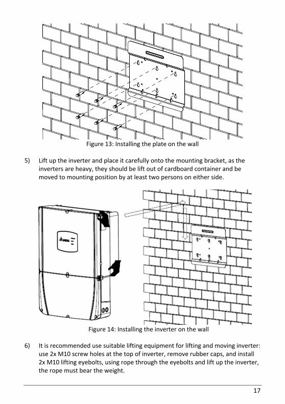
Figure 13: Installing the plate on the wall
5) Lift up the inverter and place it carefully onto the mounting bracket, as the
inverters are heavy, they should be lift out of cardboard container and be moved to mounting position by at least two persons on either side.
Figure 14: Installing the inverter on the wall
6) It is recommended use suitable lifting equipment for lifting and moving inverter: use 2x M10 screw holes at the top of inverter, remove rubber caps, and install 2x M10 lifting eyebolts, using rope through the eyebolts and lift up the inverter, the rope must bear the weight.
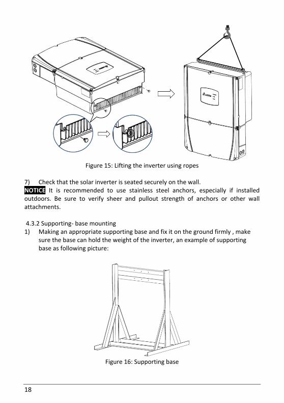
18
Figure 15: Lifting the inverter using ropes
7) Check that the solar inverter is seated securely on the wall. NOTICE It is recommended to use stainless steel anchors, especially if installed outdoors. Be sure to verify sheer and pullout strength of anchors or other wall attachments. 4.3.2 Supporting- base mounting 1) Making an appropriate supporting base and fix it on the ground firmly , make
sure the base can hold the weight of the inverter, an example of supporting base as following picture:
Figure 16: Supporting base
19
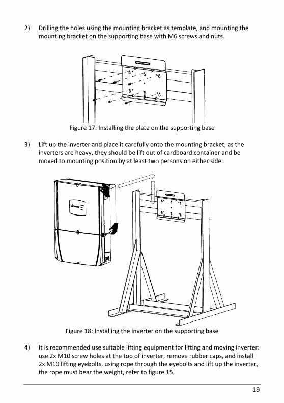
2) Drilling the holes using the mounting bracket as template, and mounting the mounting bracket on the supporting base with M6 screws and nuts.
Figure 17: Installing the plate on the supporting base
3) Lift up the inverter and place it carefully onto the mounting bracket, as the
inverters are heavy, they should be lift out of cardboard container and be moved to mounting position by at least two persons on either side.
Figure 18: Installing the inverter on the supporting base
4) It is recommended use suitable lifting equipment for lifting and moving inverter:
use 2x M10 screw holes at the top of inverter, remove rubber caps, and install 2x M10 lifting eyebolts, using rope through the eyebolts and lift up the inverter, the rope must bear the weight, refer to figure 15.
20
5) Check that the solar inverter is seated securely on the wall. NOTICE It is recommended to use stainless steel screws and nuts, especially if
installed outdoors. Be sure to verify sheer and pullout strength of screws.
5. Electrical connection and wiring
5.1 General safety and information WARNING Read all of these instructions, cautions, and warnings for the Delta inverter and associated PV array documentation. WARNING Installation and commissioning must be performed by a licensed electrician in accordance with local, state, and National Electrical Code ANSI/NFPA 70 requirements. WARNING Before connecting the Delta SOLIVIA inverter to the AC distribution grid, approval must be received by appropriate local utility as required by national and state interconnection regulations, and must be connected only by qualified personnel. DANGER PV solar arrays produce hazardous voltages and currents when exposed to light which can create an electrical shock hazard. Using dark opaque sheets cover the PV solar array before wiring or connecting cable terminations. CAUTION Use 10 AWG or greater, 90ºC (194 ºF), copper solid or stranded wire for all DC and AC wiring to Delta inverter to optimize system efficiency. CAUTION Do not attempt to open or repair the inverter as the inverter is factory sealed to maintain its NEMA 4X / IP65 rating and will void the inverter warranty.
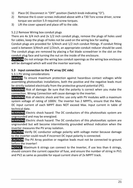
5.2 Opening the wiring box cover and conduit plugs WARNING Ensure no live voltages are present on PV input and AC output circuits, and verify that the DC disconnect, AC disconnect, and dedicated AC branch circuit breaker are in the “OFF” position, before inverter installation. 5.2.1 Opening wiring box cover
Figure 19: Removing the wiring box cover
21
1) Place DC Disconnect in “OFF” position (Switch knob indicating “O”). 2) Remove the 6 cover screws indicated above with a T30 Torx screw driver, screw
torque see section 5.9 required screw torques. 3) Lift the cover upward and place off to the side. 5.2.2 Remove Wiring box conduit plugs There are 4x 3/4 inch and 2x 1/2 inch conduit plugs, remove the plugs of holes used for cables, keep the plugs of holes not be used on the wiring box for sealing. Conduit plugs are provided for 3/4inch and 1/2 inch conduit fittings. If conduit fitting used is between 3/4inch and 1/2inch, an appropriate conduit reducer should be used. The conduit plugs are removed by placing a flat blade screwdriver in the slot on the conduit plug face and turning the nut on the inside of the enclosure. CAUTION Do not enlarge the wiring box conduit openings as the wiring box enclosure will be damaged which will void the inverter warranty.
5.3 Input connection to the PV array (DC side) 5.3.1 PV string considerations DANGER To ensure maximum protection against hazardous contact voltages while assembling photovoltaic installations, both the positive and the negative leads must be strictly isolated electrically from the protective ground potential (PE). WARNING Risk of damage: Be sure that the polarity is correct when you make the connection. Wrong Connection will cause damage to the inverter. WARNING Risk of electric shock and fire: use only with PV modules with a maximum system voltage of rating of 1000V. The inverter has 2 MPPTs, ensure that the Max. DC input current of each MPPT does NOT exceed Max. Input current in table of technical date. WARNING Electric shock hazard: The DC conductors of this photovoltaic system are ungrounded and may be energized. WARNING Electric shock hazard: The DC conductors of this photovoltaic system are ungrounded but will become intermittently grounded without indication when the inverter measures the PV array isolation. CAUTION Verify DC conductor voltage polarity with voltage meter because damage to the inverter could result if incorrect DC input polarity is connected. CAUTION The PV Array positive or negative leads must not be connected to ground before the inverter! NOTICE Maximum 6 strings can connect to the Inverter, if use less than 6 strings, should concern the current capacitor of fuse, and ensure the number of string in PV1 and PV2 as same as possible for equal current share of 2x MPPT track.
22
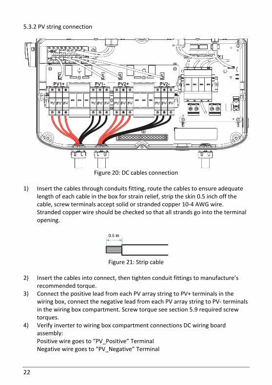
5.3.2 PV string connection
Figure 20: DC cables connection
1) Insert the cables through conduits fitting, route the cables to ensure adequate
length of each cable in the box for strain relief, strip the skin 0.5 inch off the cable, screw terminals accept solid or stranded copper 10-4 AWG wire. Stranded copper wire should be checked so that all strands go into the terminal opening.
Figure 21: Strip cable
2) Insert the cables into connect, then tighten conduit fittings to manufacture’s
recommended torque. 3) Connect the positive lead from each PV array string to PV+ terminals in the
wiring box, connect the negative lead from each PV array string to PV- terminals in the wiring box compartment. Screw torque see section 5.9 required screw torques.
4) Verify inverter to wiring box compartment connections DC wiring board assembly: Positive wire goes to “PV_Positive” Terminal Negative wire goes to “PV_Negative” Terminal
23
5.4 Selecting PV string fuse(s) NOTICE The maximum acceptable string fuse for the Inverter is 20 A (SPF020). Use of larger fuses will void the warranty. WARNING The string fuse rating should never exceed the Maximum Series Fuse Rating provided by the module manufacturer. This value is typically listed on the module label. 5.4.1 Calculating the minimum string fuse per NEC Article 690 Proper sizing of overcurrent protection is based on the maximum short circuit current Isc (module) and calculated in accordance with NEC Article 690 requirements:
The minimum string fuse size is calculated by multiplying the module Isc x 1.56.
The maximum acceptable string fuse for DELTA 15 TL, DELTA 20 TL, DELTA 24 TL and DELTA 28 TL is 20A. Use of larger fuses will void the warranty. The recommended type is SPF series solar fuse. Many fuse manufacturers may have compatible fuse types. The generic properties are: Fast-acting, Dimensions: 1 1/2” in length x 13/32” fuse diameter, Interrupt rating: >=10KA @ 1000 Vdc. UL and CSA approval of the PV fuse is mandatory.
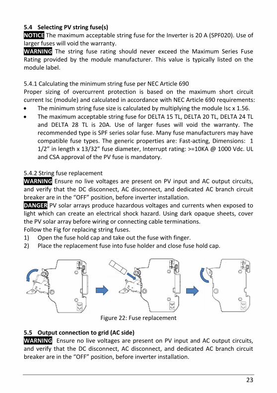
5.4.2 String fuse replacement WARNING Ensure no live voltages are present on PV input and AC output circuits, and verify that the DC disconnect, AC disconnect, and dedicated AC branch circuit breaker are in the “OFF” position, before inverter installation. DANGER PV solar arrays produce hazardous voltages and currents when exposed to light which can create an electrical shock hazard. Using dark opaque sheets, cover the PV solar array before wiring or connecting cable terminations. Follow the Fig for replacing string fuses. 1) Open the fuse hold cap and take out the fuse with finger. 2) Place the replacement fuse into fuse holder and close fuse hold cap.
Figure 22: Fuse replacement
5.5 Output connection to grid (AC side) WARNING Ensure no live voltages are present on PV input and AC output circuits, and verify that the DC disconnect, AC disconnect, and dedicated AC branch circuit breaker are in the “OFF” position, before inverter installation.
24
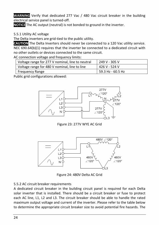
WARNING Verify that dedicated 277 Vac / 480 Vac circuit breaker in the building electrical service panel is turned-off. NOTICE The AC output (neutral) is not bonded to ground in the inverter. 5.5.1 Utility AC voltage The Delta inverters are grid-tied to the public utility. CAUTION The Delta Inverters should never be connected to a 120 Vac utility service. NEC 690.64(b)(1) requires that the inverter be connected to a dedicated circuit with no other outlets or devices connected to the same circuit. AC connection voltage and frequency limits:
Voltage range for 277 V nominal, line to neutral 249 V - 305 V
Voltage range for 480 V nominal, line to line 426 V - 524 V
Frequency Range 59.3 Hz - 60.5 Hz
Public grid configurations allowed:
Figure 23: 277V WYE AC Grid
Figure 24: 480V Delta AC Grid
5.5.2 AC circuit breaker requirements A dedicated circuit breaker in the building circuit panel is required for each Delta solar inverter that is installed. There should be a circuit breaker or fuse to protect each AC line, L1, L2 and L3. The circuit breaker should be able to handle the rated maximum output voltage and current of the inverter. Please refer to the table below to determine the appropriate circuit breaker size to avoid potential fire hazards. The

25
national Electrical Code (NEC), ANSI/NFPA 70 or applicable local electrical codes must be followed when determining maximum branch-circuit over-current protection requirements.
Inverter model Recommended AC branch protection
15KW TL 3-pole, 40 A 480 Vac
20KW TL 3-pole, 40 A 480 Vac
24KW TL 3-pole, 50 A 480 Vac
28KW TL 3-pole, 50 A 480 Vac
Please note that there is an exception to the requirement of a dedicated circuit breaker in the building circuit panel for each inverter if there exists a dedicated PV system AC subpanel that is used to combine multiple inverters. In this case, only one breaker at the main building service panel should be installed for a multiple inverter installation utilizing a dedicated PV system AC subpanel. 5.5.3 AC grid connection WARNING AC disconnect may be required by your local AHJ. Please check local regulations to determine if the AC disconnect is required for your installation. NOTICE Stranded copper wire should be checked so that all strands go into the terminal opening. NOTICE If the grid type with Neutral connection is selected, please double check whether the Neutral wire is connected reliably. The unsuccessful Neutral wire connection will make the unit fail to feed in power to the grid because of the wrong phase voltage detection.
26
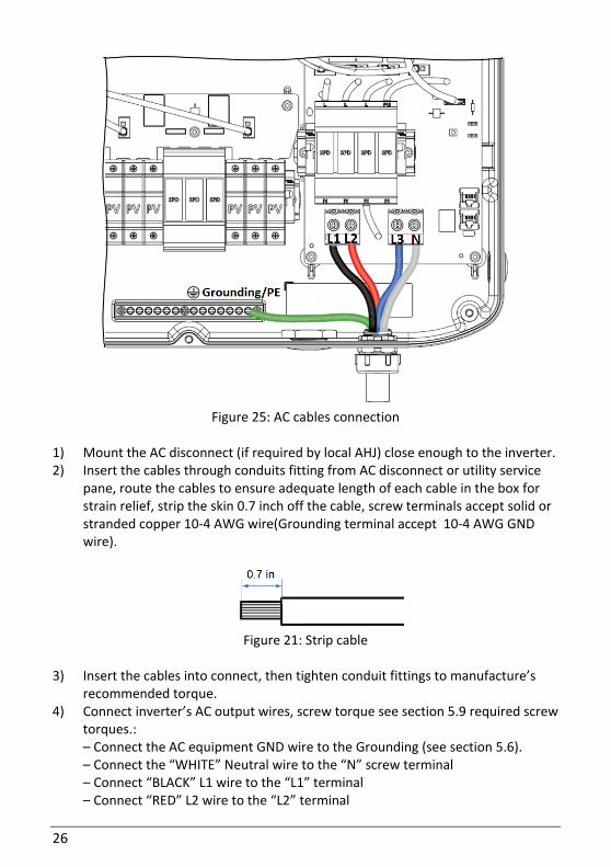
Figure 25: AC cables connection
1) Mount the AC disconnect (if required by local AHJ) close enough to the inverter. 2) Insert the cables through conduits fitting from AC disconnect or utility service
pane, route the cables to ensure adequate length of each cable in the box for strain relief, strip the skin 0.7 inch off the cable, screw terminals accept solid or stranded copper 10-4 AWG wire(Grounding terminal accept 10-4 AWG GND wire).
Figure 21: Strip cable
3) Insert the cables into connect, then tighten conduit fittings to manufacture’s
recommended torque. 4) Connect inverter’s AC output wires, screw torque see section 5.9 required screw
torques.: – Connect the AC equipment GND wire to the Grounding (see section 5.6). – Connect the “WHITE” Neutral wire to the “N” screw terminal – Connect “BLACK” L1 wire to the “L1” terminal – Connect “RED” L2 wire to the “L2” terminal
27
– Connect “BLUE” L3 wire to the “L3” terminal
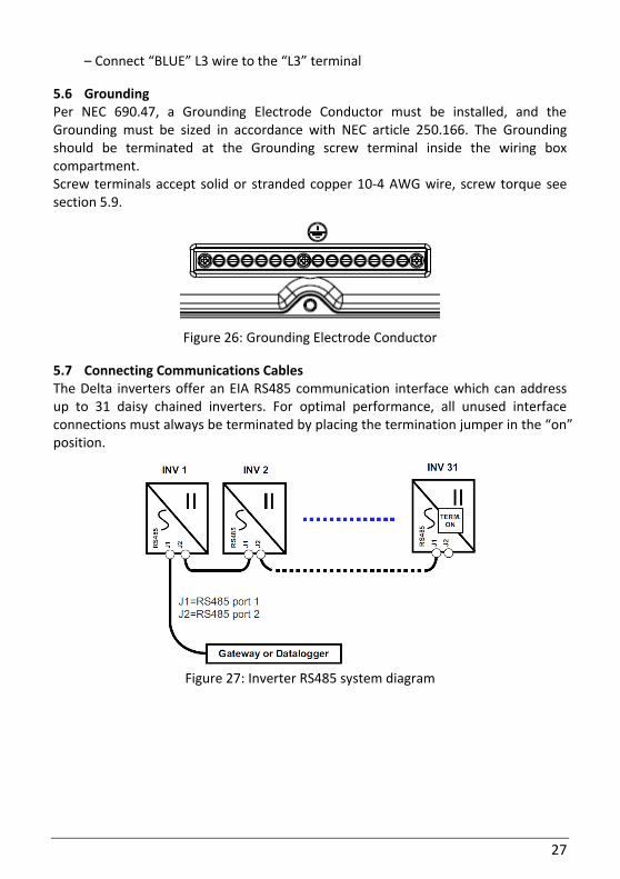
5.6 Grounding Per NEC 690.47, a Grounding Electrode Conductor must be installed, and the Grounding must be sized in accordance with NEC article 250.166. The Grounding should be terminated at the Grounding screw terminal inside the wiring box compartment. Screw terminals accept solid or stranded copper 10-4 AWG wire, screw torque see section 5.9.
Figure 26: Grounding Electrode Conductor
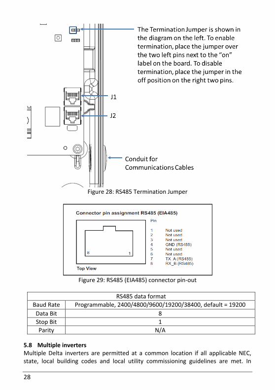
5.7 Connecting Communications Cables The Delta inverters offer an EIA RS485 communication interface which can address up to 31 daisy chained inverters. For optimal performance, all unused interface connections must always be terminated by placing the termination jumper in the “on” position.
Figure 27: Inverter RS485 system diagram
28
Figure 28: RS485 Termination Jumper
Figure 29: RS485 (EIA485) connector pin-out
RS485 data format
Baud Rate Programmable, 2400/4800/9600/19200/38400, default = 19200
Data Bit 8
Stop Bit 1
Parity N/A
5.8 Multiple inverters Multiple Delta inverters are permitted at a common location if all applicable NEC, state, local building codes and local utility commissioning guidelines are met. In
29
addition, each inverter should have its own dedicated AC branch protection circuit breaker and a dedicated PV string/array, not to exceed the inverter’s ratings.
5.9 Required screw torques
Part Description Required torque
Wiring Box Cover Screws
T30 head M6 screw(6x), for attaching the wiring box cover to the wiring box
44.4 in-lbs (5Nm)
Wiring Box Interior
Nuts
M6 nuts (6x) that secure the wiring box to the inverter stage assembly
53 in-lbs (6Nm)
PV Terminals Screws
Phil-Slot head M5 screw, for connecting PV cables terminal
30 in-lbs (3.4Nm)
AC Grid Terminals
Screws
Phil-Slot head M5 screw, for connecting AC grid cables terminal
33 in-lbs (3.7Nm)
Grounding Conductor
Slot Head 1/4-28-UNF-2B screw, for connecting grounding cables
26 in-lbs (2.9Nm)
6. Commissioning
6.1 Status LEDs The current operating state is indicated via LEDs, the designation of LEDs as following:
Label Designation Color
○ Operation Operation Green
○ Fault Failure Yellow
○ AFCI AFCI Fault Red
Normal Operating status of LEDs as following:
LED status Message category
Green Yellow Red
(ON) (OFF) (OFF)
Normal operation
Green Yellow Red
(Flash) (Flash) (OFF)
Night mode
Green Yellow Red
(Flash) (OFF) (Flash)
AFCI self-test
Failure message on the LEDs is provided in “7.2. Troubleshooting”.
6.2 Inverter turn-on procedure TBD
30
6.3 Inverter turn-off procedure TBD
6.4 Settings TBD
7. Diagnosis and Maintenance DANGER Danger of death or severe injuries from hazardous voltage: Hazardous voltage is applied to the solar power inverter during operation. Hazardous voltage is still present 5 minutes after all power sources have been disconnected. Never open the solar power inverter. The solar power inverter contains no
components that are to be maintained or repaired by the operator or installer. Opening the cover will void the warranty.
Maintenance operations must be performed after disconnected from the grid and the photovoltaic panels and waiting at least 5minute.
Disconnect the solar inverter from the grid before removing or inserting the AC connector.
DANGER Danger of death or severe injuries from hazardous voltage: Dangerous voltages can be present at the DC connections of the solar power inverter. Never disconnect the PV modules when the solar power inverter is under load.
First switch off the grid connection so that the solar power inverter cannot feed energy into the grid. Then open the DC disconnect.
Secure the DC connections against being touched. WARNING Danger of injury due to heavy weight: The solar power inverter is heavy (see technical data). Incorrect handling can lead to injuries. The solar power inverter must be lifted and carried by two people or by lift
machine.
7.1 Scheduled maintenance Scheduled maintenance are recommended to preserve the efficiency of the inverter, it is recommended maintenance operations be carried out by qualified personnel, following is Check Item of Scheduled maintenance
Inverter cleaning
Annually Clean the solar power inverter to prevent soiling of the housing, particularly heat sink is free from dust being covered.
Electrical Connection
Annually Check that cable glands and connection block screws are tight. Annually Check that cables are intact, not Scratched or broken.
System Running
Check that the inverter is operating correctly, and that no fault alarms are present. Check that the running sound is normal.
31
7.2 Troubleshooting The following table shows the failure messages and provides fault-finding and correction suggestion.
LED status Message category
Green Yellow Red
(Flash) (OFF) (OFF)
Failure
▶ Please contact Delta Support
Green Yellow Red
(Flash) (ON) (OFF)
IMI Failure
▶ Please contact Delta Support
Green Yellow Red
(Flash) (OFF) (ON)
AFCI Fault
▶ Please contact Delta Support
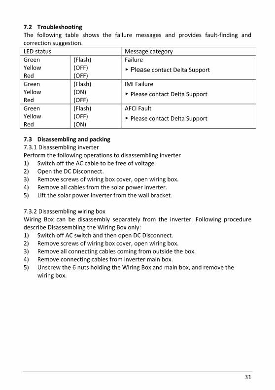
7.3 Disassembling and packing 7.3.1 Disassembling inverter Perform the following operations to disassembling inverter 1) Switch off the AC cable to be free of voltage. 2) Open the DC Disconnect. 3) Remove screws of wiring box cover, open wiring box. 4) Remove all cables from the solar power inverter. 5) Lift the solar power inverter from the wall bracket. 7.3.2 Disassembling wiring box Wiring Box can be disassembly separately from the inverter. Following procedure describe Disassembling the Wiring Box only: 1) Switch off AC switch and then open DC Disconnect. 2) Remove screws of wiring box cover, open wiring box. 3) Remove all connecting cables coming from outside the box. 4) Remove connecting cables from inverter main box. 5) Unscrew the 6 nuts holding the Wiring Box and main box, and remove the
wiring box.
32
Figure 30: Screw nuts fixing wiring box
7.3.3 Packing inverter Use the original packaging or packaging of the same quality. 7.3.4 Disposing inverter Dispose of the solar power inverter in a technically appropriate manner according to the legal requirements of your country.
8. Glossary AC Abbreviation for “Alternating Current”. AHJ Abbreviation for “Authority Having Jurisdiction”. Anti-islanding protection A unit for grid monitoring with assigned switching elements (anti-islanding protection) and is an automatic isolation point for small power generation systems (to 30 kWp). CEC Abbreviation for the California Energy Commission CEC Efficiency CEC Efficiency is the California Energy Commission Efficiency rating, a performance rating for modules and inverters based on the real environment that a system will be in. CSA Abbreviation for the Canadian Standards Association. DC Abbreviation for “Direct Current”.
33
EMC The Electro-Magnetic Compatibility (EMC) concerns the technical and legal basics of the mutual influencing of electrical devices through electromagnetic fields caused by them in electrical engineering. FCC FCC is the abbreviation for Federal Communications Commission. Galvanic isolation No conductive connection between two component parts. GET Grounding Electrode Terminal GND Ground IEEE The Institute of Electrical and Electronics Engineers or IEEE (read I-Triple-E) is an international non-profit, professional organization for the advancement of technology related to electricity. ISC Short Circuit Current MPP The Maximum Power Point is the point on the current-voltage (I-V) curve of a module, where the product of current and voltage has it’s maximum value. NEC The National Electrical Code (NEC), or NFPA 70, is a United States standard for the safe installation of electrical wiring and equipment. Nominal power Nominal power is the maximum permissible continuous power output indicated by the manufacturer for a device or a system. Usually the device is also optimized so that the efficiency is at its maximum in case of operation with nominal power. Nominal current Nominal current is the absorbed current in case of electrical devices if the device is supplied with the nominal voltage and yields its nominal power. PE In electric systems and cables a protective earth conductor is frequently employed. This is also called grounding wire, protective grounding device, soil, grounding or PE (English „protective earth“). Photovoltaics (abbr.: PV) The conversion of PV energy into electrical energy. The name is composed of the component parts: Photos - the Greek word for light - and Volta - after Alessandro Volta, a pioneer in electrical research. PV modules Part of a PV generator; converts PV energy into electrical energy. RS485 (EIA485)
34
Differential voltage interface on which the genuine signal is transmitted on one core and the negated (or negative) signal on the other core. String Designates a group of electrical PV modules switched in series. UL Stands for Underwriters Laboratory, a non-profit organization that sets standards for different product categories and tests products to make sure they meet the standards.