Embed Size (px)
Citation preview
CrystalView DVI Pro fiber ™ DVI / VGA FIBER EXTENDER
INSTALLATION AND OPERATION MANUAL
10707 Stancliff Road Phone: (281) 933-7673 Houston, Texas 77099 WWW.ROSE.COM


LIMITED WARRANTY
Copyright Rose Electronics 2006. All rights reserved. No part of this manual may be reproduced, stored in a retrieval system, or transcribed in any form or any means, electronic or mechanical, including photocopying and recording, without the prior written permission of Rose Electronics. Rose Electronics Part # MAN-CRVPF Printed In the United States of America – Revision 3.0
Rose Electronics warrants the CrystalView Pro Fiber to be in good working order for one year from the date of purchase from Rose Electronics or an authorized dealer. Should this product fail to be in good working order at any time during this one-year warranty period, Rose Electronics will, at its option, repair or replace the Unit as set forth below. Repair parts and replacement units will be either reconditioned or new. All replaced parts become the property of Rose Electronics. This limited warranty does not include service to repair damage to the Unit resulting from accident, disaster, abuse, or unauthorized modification of the Unit, including static discharge and power surges. Limited Warranty service may be obtained by delivering this unit during the one-year warranty period to Rose Electronics or an authorized repair center providing a proof of purchase date. If this Unit is delivered by mail, you agree to insure the Unit or assume the risk of loss or damage in transit, to prepay shipping charges to the warranty service location, and to use the original shipping container or its equivalent. You must call for a return authorization number first. Under no circumstances will a unit be accepted without a return authorization number. Contact an authorized repair center or Rose Electronics for further information. ALL EXPRESS AND IMPLIED WARRANTIES FOR THIS PRODUCT INCLUDING THE WARRANTIES OF MERCHANTABILITY AND FITNESS FOR A PARTICULAR PURPOSE, ARE LIMITED IN DURATION TO A PERIOD OF ONE YEAR FROM THE DATE OF PURCHASE, AND NO WARRANTIES, WHETHER EXPRESS OR IMPLIED, WILL APPLY AFTER THIS PERIOD. SOME STATES DO NOT ALLOW LIMITATIONS ON HOW LONG AN IMPLIED WARRANTY LASTS, SO THE ABOVE LIMITATION MAY NOT APPLY TO YOU. IF THIS PRODUCT IS NOT IN GOOD WORKING ORDER AS WARRANTED ABOVE, YOUR SOLE REMEDY SHALL BE REPLACEMENT OR REPAIR AS PROVIDED ABOVE. IN NO EVENT WILL ROSE ELECTRONICS BE LIABLE TO YOU FOR ANY DAMAGES INCLUDING ANY LOST PROFITS, LOST SAVINGS OR OTHER INCIDENTAL OR CONSEQUENTIAL DAMAGES ARISING OUT OF THE USE OF OR THE INABILITY TO USE SUCH PRODUCT, EVEN IF ROSE ELECTRONICS OR AN AUTHORIZED DEALER HAS BEEN ADVISED OF THE POSSIBILITY OF SUCH DAMAGES, OR FOR ANY CLAIM BY ANY OTHER PARTY. SOME STATES DO NOT ALLOW THE EXCLUSION OR LIMITATION OF INCIDENTAL OR CONSEQUENTIAL DAMAGES FOR CONSUMER PRODUCTS, SO THE ABOVE MAY NOT APPLY TO YOU. THIS WARRANTY GIVES YOU SPECIFIC LEGAL RIGHTS AND YOU MAY ALSO HAVE OTHER RIGHTS WHICH MAY VARY FROM STATE TO STATE. NOTE: This equipment has been tested and found to comply with the limits for a Class B digital device, pursuant to Part 15 of the FCC Rules. These limits are designed to provide reasonable protection against harmful interference when the equipment is operated in a commercial environment. This equipment generates, uses, and can radiate radio frequency energy and, if not installed and used in accordance with the instruction manual, may cause harmful interference to radio communications. Operation of this equipment in a residential area is likely to cause harmful interference in which case the user will be required to correct the interference at his own expense. IBM, AT, and PS/2 are trademarks of International Business Machines Corp. Microsoft and Microsoft Windows are registered trademarks of Microsoft Corp. Any other trademarks mentioned in this manual are acknowledged to be the property of the trademark owner.
FCC/IC STATEMENTS, EU DECLARATION OF CONFORMITY
FEDERAL COMMUNICATIONS COMMISSION AND INDUSTRY CANADA
RADIO-FREQUENCY INTERFERENCE STATEMENTS This equipment generates, uses and can radiate radio frequency energy and if not installed and used properly, that is in strict accordance with the manufacturer’s instructions may cause interference to radio communication. It has been tested and found to comply with the limits for a Class A digital device in accordance with the specifications of Part 15 of FCC rules, which are designed to provide reasonable protection against such interference when the equipment is operated in a commercial environment. Operation of this equipment in a residential area is likely to cause interference, in which case the user at his own expense will be required to take whatever measures may be necessary to correct the interference. Changes or modifications not expressly approved by the party responsible for compliance could void the user’s authority to operate the equipment. This digital apparatus does not exceed the Class A limits for radio noise emission from digital apparatus set out in the Radio Interference Regulation of Industry Canada. Le présent appareil numérique n’émet pas de bruits radioélectriques dépassant les limites applicables aux appareils numériques de la classe A prescrites dans le Règlement sur le brouillage radioélectrique publié par Industrie Canada.

EUROPEAN UNION DECLARATION OF CONFORMITY
CE DECLARATION OF CONFORMITY
This equipment is in conformity with the Council Directives 89/336/EEC The Declaration of Conformity is based upon compliance of the product with the following standards: EN55022: 1999 Class A EN55024: 1999 IEC61000-4-2: 2001 IEC61000-4-3: 2001 IEC61000-4.4: 2001 EN61000-3-2 2001 EN61000-3-3 2002
This equipment has been found to comply with the limits for a Class A digital device, pursuant to Part 15 of the FCC Rules. These limits are designed to provide reasonable protection against harmful interference when the equipment is operated in a commercial environment. This equipment generates, uses, and can radiate radio frequency energy and, if not installed and used in accordance with the instruction manual, may cause harmful interference to radio communications. Operation of this equipment in a residential area is likely to cause harmful interference in which case the user will be required to correct the interference at his own expense.
TABLE of CONTENTS
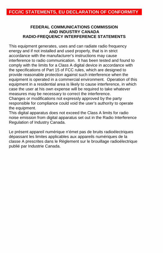
Contents Page # Disclaimer ............................................................................................... 1 System Introduction ................................................................................ 1
Features .............................................................................................. 2 Compatibility ........................................................................................... 2 DVI or VGA ............................................................................................. 3 PC Model ................................................................................................ 4 SUN Model ............................................................................................. 5 USB Model ............................................................................................. 6 Rack Model ............................................................................................. 6 Optical Elements .................................................................................... 7 Cables .................................................................................................... 7 Device Control -OSD .............................................................................. 8 OSD Menu descriptions ......................................................................... 9
Menu descriptions ............................................................................... 9 Installation ............................................................................................ 15
Transmitter to Receiver cabling ........................................................ 16 SET-UP instructions (Mixed DVI and VGA) ...................................... 17 Additional keyboard commands........................................................ 19 Applying power ................................................................................. 19
Operating instructions .......................................................................... 20 Private Mode ........................................................................................ 20 Frame Rates ......................................................................................... 20 Troubleshooting .................................................................................... 21 Service Information .............................................................................. 22
Maintenance and Repair ................................................................... 22 Technical Support ............................................................................. 22
Safety ................................................................................................... 23 Tables Page # Table 1. Timeout / switching method...................................................... 3 Table 2. Transmitter to receiver cabling ............................................... 16 Table 3. Pixel clock /phase examples .................................................. 18 Figures Page # Figure 1. PC Model ................................................................................ 4 Figure 2. SUN Model .............................................................................. 5 Figure 3. USB Model .............................................................................. 6 Figure 4. Input Select Menu ................................................................... 9 Figure 5. Scale mode menu ................................................................... 9 Figure 6. Brightness/Contrast menu..................................................... 10 Figure 7. Color / Color temp menu ....................................................... 11 Figure 8. Image menu .......................................................................... 12 Figure 9. Tools menu ........................................................................... 13 Figure 10. Save menu .......................................................................... 14 Figure 11. Typical cabling configurations ............................................. 15
INTRODUCTION
CRYSTALVIEW PRO FIBER INSTALLATION AND OPERATIONS MANUAL 1
Disclaimer While every precaution has been taken in the preparation of this manual, the manufacturer assumes no responsibility for errors or omissions. Neither does the manufacturer assume any liability for damages resulting from the use of the information contained herein. The manufacturer reserves the right to change the specifications, functions, or circuitry of the product without notice. The manufacturer cannot accept liability for damages due to misuse of the product or other circumstances outside the manufacturer’s control. The manufacturer will not be responsible for any loss, damage, or injury arising directly or indirectly from the use of this product.
System Introduction Thank you for choosing the Rose Electronics CrystalView Pro Fiber KVM station extender. The CrystalView Pro Fiber is a very versatile KVM extender. It supports the latest digital DVI as well as analog VGA. All combinations of DVI and VGA monitors and video cards are supported. With this flexibility, you can connect a VGA video card to a DVI monitor, or a DVI video card to a VGA monitor. The modular architecture design of the CrystalView Pro Fiber provides the flexibility to support PS/2 and SUN connections and different cable types such as Multimode fiber and Singlemode fiber. A serial port can be added to support Touch-Screen. Stereo audio, USB, parallel port and other custom interfaces can also be added. The system consists of two Units, a transmitter and a receiver. The transmitter connects to your CPU or a Rose switch and the receiver connects to a keyboard, video monitor and mouse or KVM station. The transmitter and receiver are connected together with industry standard multimode or singlemode fiber optic cable. The receiver can be up to 33,000 feet from the transmitter using singlemode fiber cable The CrystalView Pro Fiber is available in several models, the PC model, the Sun model and a USB model. The PC model is available with transmitter and receiver KVM access. The transmitter KVM version allows an additional KVM station to be connected to the transmitter unit. Using the CrystalView Pro Fiber to remotely access your computer has several advantages over conventional CAT-5 cable. Using fiber cable, you can extend the distance between the transmitter and receiver up to 33,000 feet. In addition, fiber cable is unaffected by electromagnetic interference, keeping your data safe from interference by lightning and over voltage transients. Computers used in hazardous industrial environments can be accessed remotely, keeping the users safe and unexposed to any hazards.
2 CRYSTALVIEW PRO FIBER INSTALLATION AND OPERATIONS MANUAL
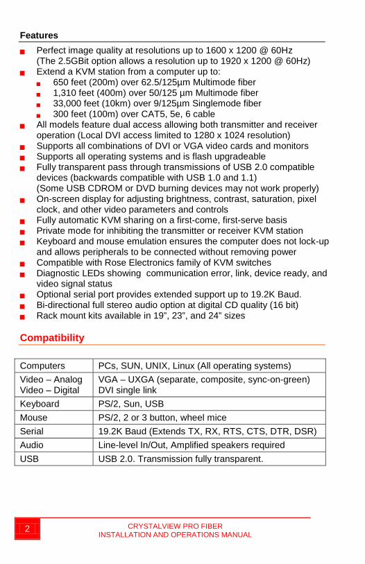
Features Perfect image quality at resolutions up to 1600 x 1200 @ 60Hz
(The 2.5GBit option allows a resolution up to 1920 x 1200 @ 60Hz) Extend a KVM station from a computer up to:
650 feet (200m) over 62.5/125µm Multimode fiber 1,310 feet (400m) over 50/125 µm Multimode fiber 33,000 feet (10km) over 9/125µm Singlemode fiber 300 feet (100m) over CAT5, 5e, 6 cable
All models feature dual access allowing both transmitter and receiver operation (Local DVI access limited to 1280 x 1024 resolution)
Supports all combinations of DVI or VGA video cards and monitors Supports all operating systems and is flash upgradeable Fully transparent pass through transmissions of USB 2.0 compatible
devices (backwards compatible with USB 1.0 and 1.1) (Some USB CDROM or DVD burning devices may not work properly)
On-screen display for adjusting brightness, contrast, saturation, pixel clock, and other video parameters and controls
Fully automatic KVM sharing on a first-come, first-serve basis Private mode for inhibiting the transmitter or receiver KVM station Keyboard and mouse emulation ensures the computer does not lock-up
and allows peripherals to be connected without removing power Compatible with Rose Electronics family of KVM switches Diagnostic LEDs showing communication error, link, device ready, and
video signal status Optional serial port provides extended support up to 19.2K Baud. Bi-directional full stereo audio option at digital CD quality (16 bit) Rack mount kits available in 19”, 23”, and 24” sizes
Compatibility Computers PCs, SUN, UNIX, Linux (All operating systems) Video – Analog Video – Digital
VGA – UXGA (separate, composite, sync-on-green) DVI single link
Keyboard PS/2, Sun, USB Mouse PS/2, 2 or 3 button, wheel mice Serial 19.2K Baud (Extends TX, RX, RTS, CTS, DTR, DSR) Audio Line-level In/Out, Amplified speakers required USB USB 2.0. Transmission fully transparent.
CRYSTALVIEW PRO FIBER INSTALLATION AND OPERATIONS MANUAL 3
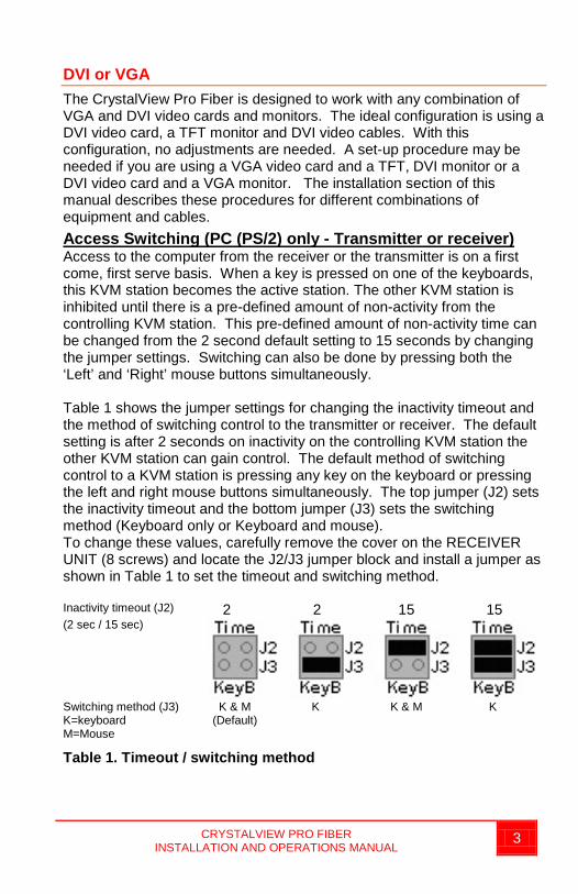
DVI or VGA The CrystalView Pro Fiber is designed to work with any combination of VGA and DVI video cards and monitors. The ideal configuration is using a DVI video card, a TFT monitor and DVI video cables. With this configuration, no adjustments are needed. A set-up procedure may be needed if you are using a VGA video card and a TFT, DVI monitor or a DVI video card and a VGA monitor. The installation section of this manual describes these procedures for different combinations of equipment and cables. Access Switching (PC (PS/2) only - Transmitter or receiver) Access to the computer from the receiver or the transmitter is on a first come, first serve basis. When a key is pressed on one of the keyboards, this KVM station becomes the active station. The other KVM station is inhibited until there is a pre-defined amount of non-activity from the controlling KVM station. This pre-defined amount of non-activity time can be changed from the 2 second default setting to 15 seconds by changing the jumper settings. Switching can also be done by pressing both the ‘Left’ and ‘Right’ mouse buttons simultaneously. Table 1 shows the jumper settings for changing the inactivity timeout and the method of switching control to the transmitter or receiver. The default setting is after 2 seconds on inactivity on the controlling KVM station the other KVM station can gain control. The default method of switching control to a KVM station is pressing any key on the keyboard or pressing the left and right mouse buttons simultaneously. The top jumper (J2) sets the inactivity timeout and the bottom jumper (J3) sets the switching method (Keyboard only or Keyboard and mouse). To change these values, carefully remove the cover on the RECEIVER UNIT (8 screws) and locate the J2/J3 jumper block and install a jumper as shown in Table 1 to set the timeout and switching method. Inactivity timeout (J2) 2 2 15 15 (2 sec / 15 sec)
Switching method (J3) K=keyboard M=Mouse
K & M (Default)
K K & M K
Table 1. Timeout / switching method
MODELS
4 CRYSTALVIEW PRO FIBERINSTALLATION AND OPERATIONS MANUAL
PC Model
Receiver
Transmitter
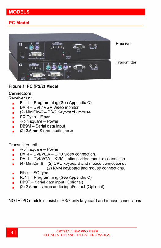
Figure 1. PC (PS/2) Model
Connectors:Receiver unit
RJ11 – Programming (See Appendix C) DVI-I – DVI / VGA Video monitor (2) MiniDin-6 – PS/2 Keyboard / mouse SC-Type – Fiber 4-pin square – Power DB9M – Serial data input (2) 3.5mm Stereo audio jacks
Transmitter unit 4-pin square – Power DVI-I – DVI/VGA – CPU video connection. DVI-I – DVI/VGA – KVM stations video monitor connection. (4) MiniDin-6 – (2) CPU keyboard and mouse connections /
(2) KVM keyboard and mouse connections. Fiber – SC-type RJ11 – Programming (See Appendix C) DB9F – Serial data input (Optional) (2) 3.5mm stereo audio input/output (Optional)
NOTE: PC models consist of PS/2 only keyboard and mouse connections
CRYSTALVIEW PRO FIBERINSTALLATION AND OPERATIONS MANUAL
5
SUN Model
Receiver
Transmitter
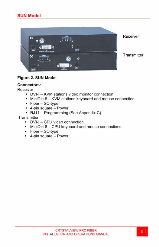
Figure 2. SUN Model
Connectors:Receiver
DVI-I – KVM stations video monitor connection. MiniDin-8 – KVM stations keyboard and mouse connection. Fiber – SC-type 4-pin square – Power RJ11 – Programming (See Appendix C)
Transmitter DVI-I – CPU video connection. MiniDin-8 – CPU keyboard and mouse connections. Fiber – SC-type 4-pin square – Power
6 CRYSTALVIEW PRO FIBERINSTALLATION AND OPERATIONS MANUAL
USB Model
Receiver
Transmitter
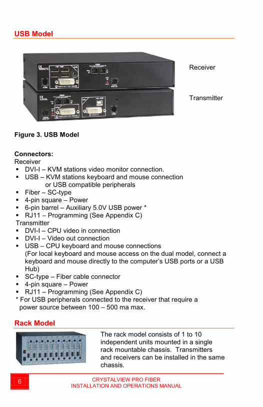
Figure 3. USB Model
Connectors:Receiver DVI-I – KVM stations video monitor connection. USB – KVM stations keyboard and mouse connection
or USB compatible peripherals Fiber – SC-type 4-pin square – Power 6-pin barrel – Auxiliary 5.0V USB power * RJ11 – Programming (See Appendix C)Transmitter DVI-I – CPU video in connection DVI-I – Video out connection USB – CPU keyboard and mouse connections
(For local keyboard and mouse access on the dual model, connect a keyboard and mouse directly to the computer’s USB ports or a USB Hub)
SC-type – Fiber cable connector 4-pin square – Power RJ11 – Programming (See Appendix C) * For USB peripherals connected to the receiver that require apower source between 100 – 500 ma max.
Rack ModelThe rack model consists of 1 to 10 independent units mounted in a single rack mountable chassis. Transmitters and receivers can be installed in the same chassis.
OPTICAL ELEMENTS / CABLES
CRYSTALVIEW PRO FIBER INSTALLATION AND OPERATIONS MANUAL 7
Optical Elements The Multimode models are Class 1 laser products and comply with IEC 825-1 and FDA 21 CFR 1040.10 and 1040.11 The Singlemode models are Class 1 laser products and comply with IEC 60825-1 and FDA 21 CFR 1040.10 and 1040.11 The optical ports of the modules must be terminated with an optical connector or with a dust plug.
Cables Transmitter to computer A CPU adapter cable connects from the transmitter to a computer’s keyboard, monitor, and mouse ports. The type of CPU adapter cable needed depends on the model, PC, Sun, or USB. Receiver to KVM station The keyboard, monitor, and mouse cables on a KVM station can connect directly to the receiver’s keyboard, monitor, and mouse ports and to these ports on the transmitter (PC model). Transmitter to Receiver cables Different fiber cable types can be used to extend the transmitter unit from the receiver unit. Extend the distance: Up to 650 feet (200m) using 62.2µm multimode fiber cable Up to 1,310 feet (400m) using 50.0µm multimode fiber cable Up to 33,000 feet (10km) using 9µm singlemode fiber cable
ON-SCREEN DISPLAY (OSD)
8 CRYSTALVIEW PRO FIBER INSTALLATION AND OPERATIONS MANUAL
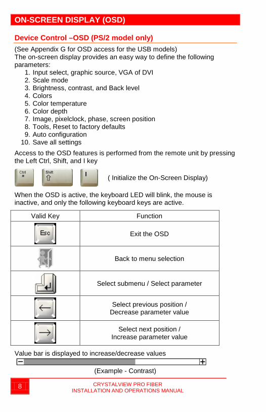
Device Control –OSD (PS/2 model only) (See Appendix G for OSD access for the USB models) The on-screen display provides an easy way to define the following parameters:
1. Input select, graphic source, VGA of DVI 2. Scale mode 3. Brightness, contrast, and Back level 4. Colors 5. Color temperature 6. Color depth 7. Image, pixelclock, phase, screen position 8. Tools, Reset to factory defaults 9. Auto configuration
10. Save all settings
Access to the OSD features is performed from the remote unit by pressing the Left Ctrl, Shift, and I key
( Initialize the On-Screen Display)
When the OSD is active, the keyboard LED will blink, the mouse is inactive, and only the following keyboard keys are active.
Valid Key Function
Exit the OSD
Back to menu selection
Select submenu / Select parameter
Select previous position / Decrease parameter value
Select next position / Increase parameter value
Value bar is displayed to increase/decrease values
(Example - Contrast)
CRYSTALVIEW PRO FIBER INSTALLATION AND OPERATIONS MANUAL 9
OSD Menu descriptions
Menu descriptions
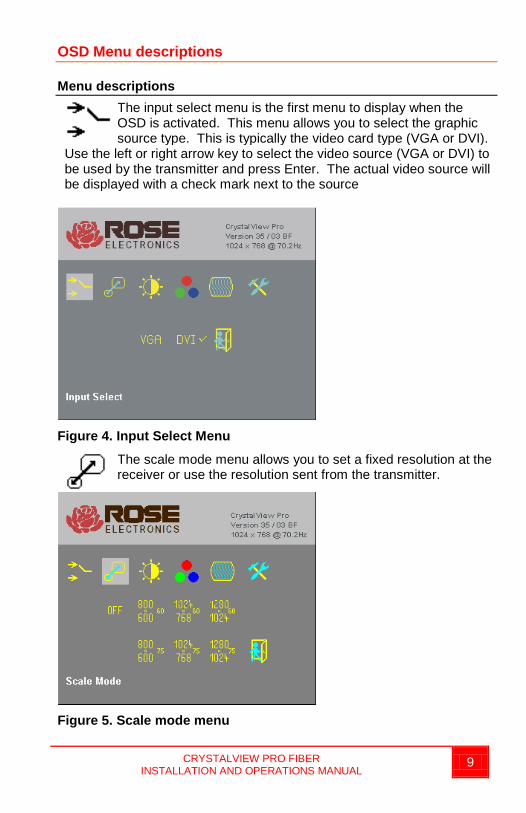
The input select menu is the first menu to display when the OSD is activated. This menu allows you to select the graphic source type. This is typically the video card type (VGA or DVI).
Use the left or right arrow key to select the video source (VGA or DVI) to be used by the transmitter and press Enter. The actual video source will be displayed with a check mark next to the source
Figure 4. Input Select Menu
The scale mode menu allows you to set a fixed resolution at the receiver or use the resolution sent from the transmitter.
Figure 5. Scale mode menu
10 CRYSTALVIEW PRO FIBER INSTALLATION AND OPERATIONS MANUAL
The receiver will always generate an exact reproduction of the source signal (up to the max resolution of the unit) if the Fixed Resolution is set to “OFF”. The fixed resolution setting should be used if the monitor resolution on the receiver is not capable of displaying the resolution sent by the transmitter. If the transmitter is connected to a KVM switch with several computers with different video resolutions, setting the receiver to a fixed resolution eliminates the need for the receiver to adjust to the sent resolution when switching between computers. The received image will display faster when switching between computers if you use a fixed resolution setting. You can increase of decrease the fixed resolution with a VGA input source but only increase the resolution with a DVI input source. Decreasing the resolution of a DVI source has no effect.
Use the arrow keys to select the needed fixed resolution and refresh rate and then press enter to accept the new setting.
NOTE: Refresh rates of 60Hz are best for LCD displays, 75Hz for CRT’s.
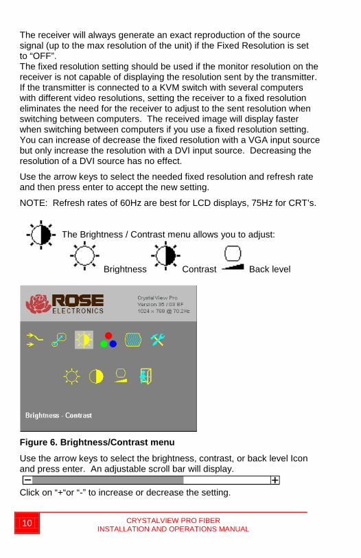
The Brightness / Contrast menu allows you to adjust:
Brightness Contrast Back level
Figure 6. Brightness/Contrast menu
Use the arrow keys to select the brightness, contrast, or back level Icon and press enter. An adjustable scroll bar will display.
Click on “+“or “-” to increase or decrease the setting.
CRYSTALVIEW PRO FIBER INSTALLATION AND OPERATIONS MANUAL 11
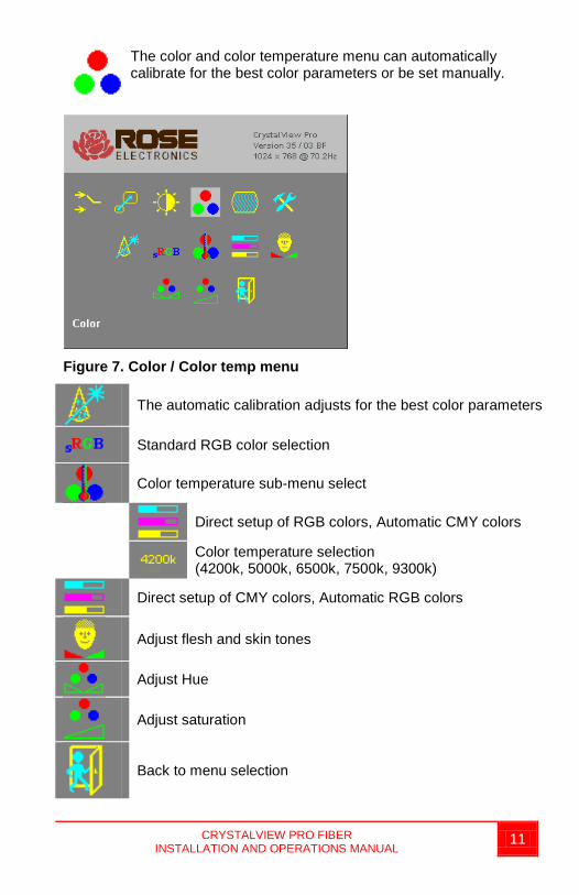
The color and color temperature menu can automatically calibrate for the best color parameters or be set manually.
Figure 7. Color / Color temp menu
The automatic calibration adjusts for the best color parameters
Standard RGB color selection
Color temperature sub-menu select
Direct setup of RGB colors, Automatic CMY colors
Color temperature selection (4200k, 5000k, 6500k, 7500k, 9300k)
Direct setup of CMY colors, Automatic RGB colors
Adjust flesh and skin tones
Adjust Hue
Adjust saturation
Back to menu selection
12 CRYSTALVIEW PRO FIBER INSTALLATION AND OPERATIONS MANUAL
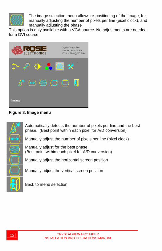
The image selection menu allows re-positioning of the image, for manually adjusting the number of pixels per line (pixel clock), and manually adjusting the phase
This option is only available with a VGA source. No adjustments are needed for a DVI source.
Figure 8. Image menu
Automatically detects the number of pixels per line and the best phase. (Best point within each pixel for A/D conversion)
Manually adjust the number of pixels per line (pixel clock)
Manually adjust for the best phase. (Best point within each pixel for A/D conversion)
Manually adjust the horizontal screen position
Manually adjust the vertical screen position
Back to menu selection
CRYSTALVIEW PRO FIBER INSTALLATION AND OPERATIONS MANUAL 13
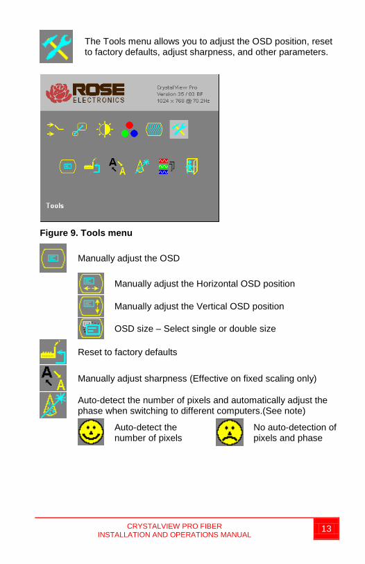
The Tools menu allows you to adjust the OSD position, reset to factory defaults, adjust sharpness, and other parameters.
Figure 9. Tools menu
Manually adjust the OSD
Manually adjust the Horizontal OSD position
Manually adjust the Vertical OSD position
OSD size – Select single or double size
Reset to factory defaults
Manually adjust sharpness (Effective on fixed scaling only)
Auto-detect the number of pixels and automatically adjust the phase when switching to different computers.(See note)
Auto-detect the number of pixels
No auto-detection of pixels and phase
14 CRYSTALVIEW PRO FIBER INSTALLATION AND OPERATIONS MANUAL
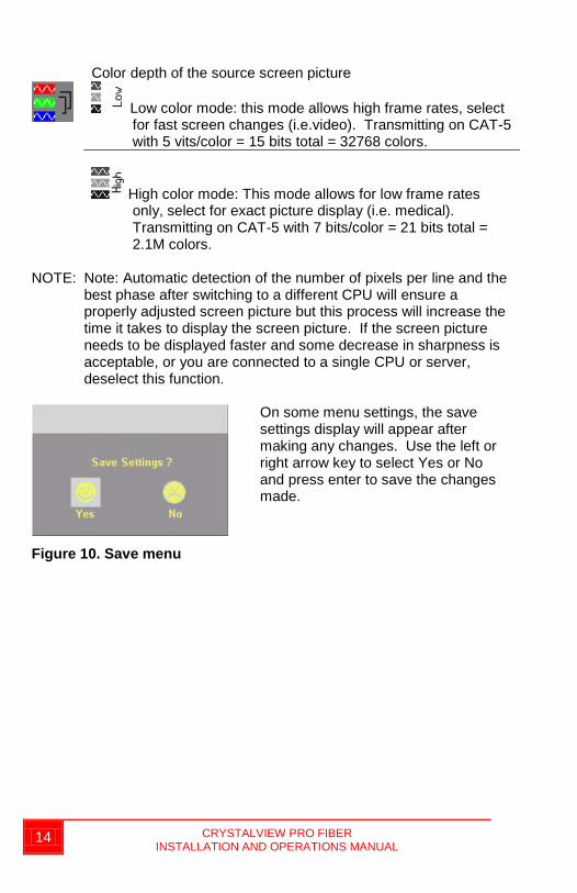
Color depth of the source screen picture
Low color mode: this mode allows high frame rates, select
for fast screen changes (i.e.video). Transmitting on CAT-5 with 5 vits/color = 15 bits total = 32768 colors.
High color mode: This mode allows for low frame rates only, select for exact picture display (i.e. medical). Transmitting on CAT-5 with 7 bits/color = 21 bits total = 2.1M colors.
NOTE: Note: Automatic detection of the number of pixels per line and the best phase after switching to a different CPU will ensure a properly adjusted screen picture but this process will increase the time it takes to display the screen picture. If the screen picture needs to be displayed faster and some decrease in sharpness is acceptable, or you are connected to a single CPU or server, deselect this function.
On some menu settings, the save settings display will appear after making any changes. Use the left or right arrow key to select Yes or No and press enter to save the changes made.
Figure 10. Save menu
INSTALLATION
CRYSTALVIEW PRO FIBER INSTALLATION AND OPERATIONS MANUAL 15
Installation Please refer to the safety section first before proceeding with any installation or configuration of the CrystalView Pro Fiber. NOTE: If your CPU uses a DVI video card and the KVM station’s monitor is a TFT (flat panel) DVI monitor, pixelclock and phase adjustments should not be needed. Refer to the set-up section for mixed VGA and DVI equipment installation. The CrystalView Pro Fiber’s design does not support plug & play on the local KVM access models. When installing the CrystalView Pro Fiber, locate the transmitter as close as possible to the CPU or switch. Keep the CPU cables as short as possible but still give some freedom of movement. Using shorter VGA cables keeps the video noise to a minimum and reduces installation costs. You can mount the CrystalView Pro Fiber in a CPU rack with the optional rack mount kit. When mounting the units in a rack, follow the instructions in Appendix D and Appendix E. Provide adequate air circulation to assure that the maximum operating temperature is not exceeded. Wherever the transmitter and receiver units are located, they should be on a secure surface and free from obstructions and objects that may cause damage to the units.
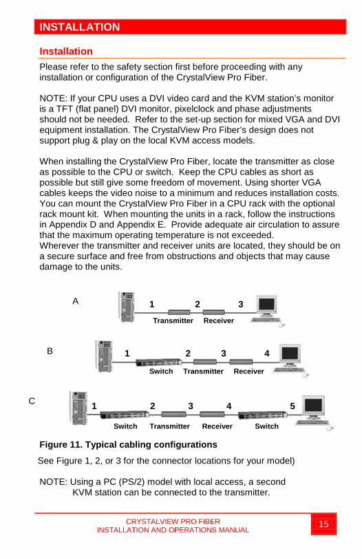
Figure 11. Typical cabling configurations
See Figure 1, 2, or 3 for the connector locations for your model)
NOTE: Using a PC (PS/2) model with local access, a second KVM station can be connected to the transmitter.
A
B
C
1 2 3 Transmitter Receiver
Switch Transmitter Receiver
Switch Transmitter Receiver Switch
1 2 3 4
1 2 3 4 5
16 CRYSTALVIEW PRO FIBER INSTALLATION AND OPERATIONS MANUAL
Refer to Figure 11 for the set-up for your system application. A. 1- Connect the appropriate CPU cable to the keyboard, video
monitor and mouse ports on the CPU and to the corresponding ports on the transmitter. 2- Connect the transmitter to the receiver with cable defined for your system (CAT-5 or Fiber optic) 3- Connect the KVM stations keyboard, video monitor, and mouse cables to the corresponding connectors on the receiver unit.
B. 1- Connect the appropriate CPU cable to the keyboard, video monitor and mouse ports on the CPU and to the appropriate CPU connector on the switch. 2- Connect the appropriate KVM cable from the KVM port on the switch to the corresponding connectors on the transmitter. 3- Connect the transmitter to the receiver with cable defined for your system (CAT-5 or Fiber optic) 4- Connect the KVM stations keyboard, video monitor, and mouse cables to the corresponding connector on the receiver unit.
C. 1- Connect the appropriate CPU cable to the keyboard, video monitor and mouse ports on the CPU and to the appropriate CPU connector on the switch. 2- Connect the appropriate KVM cable from the KVM port on the switch to the corresponding connectors on the transmitter. 3- Connect the transmitter to the receiver with cable defined for your system (CAT-5 or Fiber optic). 4- Connect the appropriate CPU cable from the CPU port on the switch to the corresponding connectors on the receiver 5-Connect the KVM stations keyboard, monitor, and mouse cables to the corresponding connector on the receiver unit.
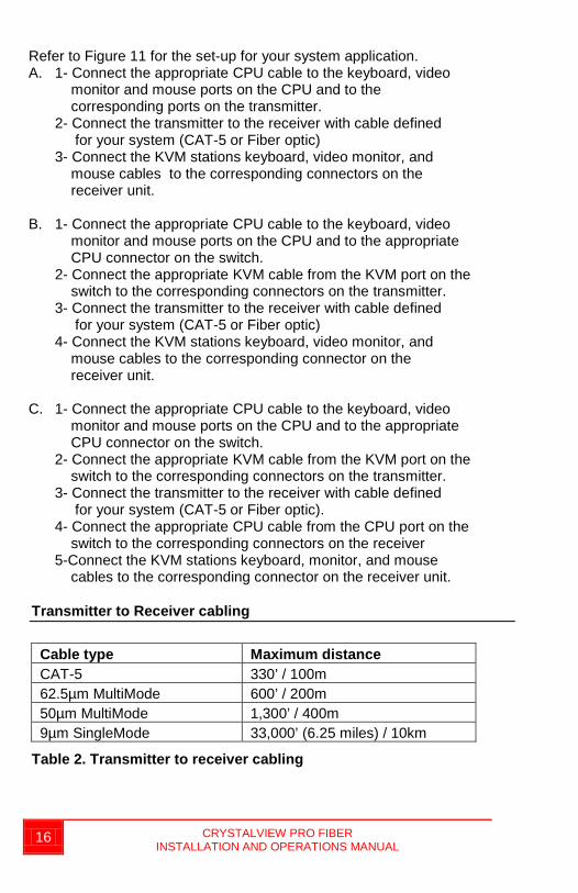
Transmitter to Receiver cabling
Cable type Maximum distance CAT-5 330’ / 100m 62.5µm MultiMode 600’ / 200m 50µm MultiMode 1,300’ / 400m 9µm SingleMode 33,000’ (6.25 miles) / 10km
Table 2. Transmitter to receiver cabling
CRYSTALVIEW PRO FIBER INSTALLATION AND OPERATIONS MANUAL 17
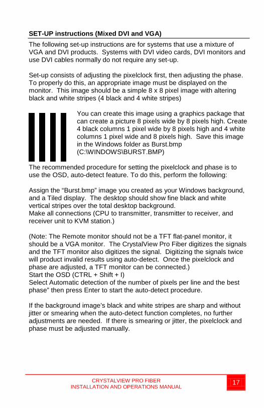
SET-UP instructions (Mixed DVI and VGA) The following set-up instructions are for systems that use a mixture of VGA and DVI products. Systems with DVI video cards, DVI monitors and use DVI cables normally do not require any set-up. Set-up consists of adjusting the pixelclock first, then adjusting the phase. To properly do this, an appropriate image must be displayed on the monitor. This image should be a simple 8 x 8 pixel image with altering black and white stripes (4 black and 4 white stripes)
You can create this image using a graphics package that can create a picture 8 pixels wide by 8 pixels high. Create 4 black columns 1 pixel wide by 8 pixels high and 4 white columns 1 pixel wide and 8 pixels high. Save this image in the Windows folder as Burst.bmp (C:\WINDOWS\BURST.BMP)
The recommended procedure for setting the pixelclock and phase is to use the OSD, auto-detect feature. To do this, perform the following: Assign the “Burst.bmp” image you created as your Windows background, and a Tiled display. The desktop should show fine black and white vertical stripes over the total desktop background. Make all connections (CPU to transmitter, transmitter to receiver, and receiver unit to KVM station.) (Note: The Remote monitor should not be a TFT flat-panel monitor, it should be a VGA monitor. The CrystalView Pro Fiber digitizes the signals and the TFT monitor also digitizes the signal. Digitizing the signals twice will product invalid results using auto-detect. Once the pixelclock and phase are adjusted, a TFT monitor can be connected.) Start the OSD (CTRL + Shift + I) Select Automatic detection of the number of pixels per line and the best phase” then press Enter to start the auto-detect procedure. If the background image’s black and white stripes are sharp and without jitter or smearing when the auto-detect function completes, no further adjustments are needed. If there is smearing or jitter, the pixelclock and phase must be adjusted manually.
18 CRYSTALVIEW PRO FIBER INSTALLATION AND OPERATIONS MANUAL
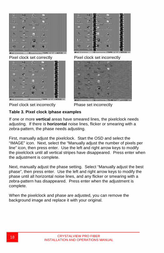
Pixel clock set correctly Pixel clock set incorrectly
Pixel clock set incorrectly Phase set incorrectly
Table 3. Pixel clock /phase examples
If one or more vertical areas have smeared lines, the pixelclock needs adjusting. If there is horizontal noise lines, flicker or smearing with a zebra-pattern, the phase needs adjusting. First, manually adjust the pixelclock. Start the OSD and select the “IMAGE” icon. Next, select the “Manually adjust the number of pixels per line” icon, then press enter. Use the left and right arrow keys to modify the pixelclock until all vertical stripes have disappeared. Press enter when the adjustment is complete. Next, manually adjust the phase setting. Select “Manually adjust the best phase”, then press enter. Use the left and right arrow keys to modify the phase until all horizontal noise lines, and any flicker or smearing with a zebra-pattern has disappeared. Press enter when the adjustment is complete. When the pixelclock and phase are adjusted, you can remove the background image and replace it with your original.
CRYSTALVIEW PRO FIBER INSTALLATION AND OPERATIONS MANUAL 19
Additional keyboard commands • Private mode - <Ctrl> + <Shift> + <Scroll Lock>
(Issue from the transmitter or receiver to disable use from the NON-issuing unit)
• Keyboard and mouse reset - <Ctrl> + <Shift> + <F4> (Issue from the transmitter or receiver to request a reset of the keyboard and mouse)
• Reset to factory defaults - <Ctrl> + <Shift> + <Esc> (Issue from the receiver only to reset the unit to factory defaults)
Applying power Plug in the provided power adapters to a 110/220-volt source and to the power connector on the transmitter and receiver Unit. Only use the power adapter provided. GND and earth should not be connected. Mount ferrite rings in the DC lines to protect against electromagnetic interference. Boot up the connected CPU and wait for it to completely boot-up. The two LEDs on each side of the fiber cable connector indicate the following: Red LED, communication status Off – no communication errors Slow blinking – one or more communication errors occurred over a 60-
minute period. Fast blinking – Several communication errors occurred over a 60-
minute period. Green LED, Link status On – power is on and link connection is locked. Blinking – Fiber cable not connected or damaged. The two LEDs next to the power connector indicate the following: Both LEDs on – system booted correctly. Only one LED on – unknown video mode being used.
OPERATING INSTRUCTIONS
20 CRYSTALVIEW PRO FIBER INSTALLATION AND OPERATIONS MANUAL
Operating instructions Once the transmitter and receiver units are connected and configured, the KVM station will function as if it were directly connected to a CPU or KVM switch. All applications, upgrades and PC configurations can be performed normally. If your transmitter is connected to a KVM switch, refer to the switches manual for the proper method of switching to different CPU ports. Operating instructions – Local KVM access The CrystalView Pro Fiber with local KVM access allows an additional KVM station to be connected to the transmitter. The CPU or KVM switch can easily be operated from the remote KVM station or the local KVM station but not simultaneously. The transmitter is active during boot-up and the connected CPUs video is displayed on both the transmitter and remote KVM stations monitor. The local monitor video displays the computer video (no DVI to VGA or VGA to DVI conversion). To activate the receiver’s KVM station, simply press any key on the KVM stations keyboard. To activate the transmitters KVM station, press any key on the KVM station’s keyboard. Private Mode On PC (PS/2) systems, a user at one console can lock out the other console by triggering a ‘Private Mode’ function. This prevents the inactive console from being used, even if the inactivity timeout period expires. To start a Private Mode session on a console, press the ‘hot’ key command sequence: <Ctrl> + <Shift> + <Scroll Lock> On the other console, to indicate that a Private Mode session has been started, the extender system: Illuminates the keyboards Num, Caps, and Scroll Lock LEDs Displays a blank image on the console’s monitor. Locks the keyboard and mouse. To end the Private Mode session, press the ‘hot’ key command sequence again. Frame Rates Normally the data rate of a DVI video card is much higher than the transfer rate of the CrystalView pro fiber modules, consequentially, not every frame of the graphic card is transferred. Stating with a recognized VS-signal, the next complete frame generated by the graphic card is digitized (VGA only) and temporally stored, transmitted to the receiver using the available net data rate and displayed. Images generated by the graphic card during the transfer are discarded (frame dropping). The resulting frame rate is approximately 15 fps. Reducing the screen resolution will increase the frame rate, increasing the screen resolution will decrease the frame rate.
TROUBLESHOOTING
CRYSTALVIEW PRO FIBER INSTALLATION AND OPERATIONS MANUAL 21
Troubleshooting The troubleshooting section is used as a guide to understanding the capabilities of the CrystalView Fiber and for general troubleshooting. If you have any problems or questions concerning the installation, operation or usage of the CrystalView Fiber that is not covered in this manual, please contact Rose Electronics for technical support.
PC boots with no error messages but keyboard does not work. Cable is loose, re-seat keyboard cable at the CPU and the transmitter. Keyboard and mouse cables reversed. Try a different model of keyboard. If the new keyboard works, the
original one may not be compatible. Some older auto-sensing keyboards may not work with this product.
Wrong or missing characters from those typed. Power down and reboot the system. PS/2 cursor appears on the screen, but mouse doesn’t work. Cable is loose, re-seat the mouse cable Keyboard and mouse cables reversed. Try a different model of mouse. Power off and on the Unit System does not detect PS/2 mouse or application cannot find mouse. Keyboard and mouse cables reversed. Cable is loose, re-seat mouse cable on the CPU and transmitter. Reboot PC.
Keyboard and Mouse have locked up. Reset PC and the receiver Unit. Check power to the receiver Unit. No picture The Fiber optical cable is not connected at the transmitter and/or the
receiver unit. One of more fibers broken. DO NOT LOOK INTO A FIBERS END
DIRECTLY WHILE IT IS CONNECTED TO THE TRANSMITTER OR RECEIVER UNIT. EYE HAZARD MAY OCCUR.
Wrong fiber type. Fiber cable must be 50µ or 62.5µ at a MultiMode unit and 9µ at a SingleMode device. Other fiber types and poly-fibers are not supported.
Horizontal jittering in picture Phase adjustment incorrect Manually or auto-detect the phase
setting. (See Figure 9) Smeared characters Pixelclock adjustment incorrect. Manually or auto-detect the pixelclock
setting (See Figure 9)
SERVICE
22 CRYSTALVIEW PRO FIBER INSTALLATION AND OPERATIONS MANUAL
Service Information Maintenance and Repair This Unit does not contain any internal user-serviceable parts. In the event a Unit needs repair or maintenance, you must first obtain a Return Authorization (RA) number from Rose Electronics or an authorized repair center. This Return Authorization number must appear on the outside of the shipping container. See Limited Warranty for more information. When returning a Unit, it should be double-packed in the original container or equivalent, insured and shipped to: Rose Electronics Attn: RA__________ 10707 Stancliff Road Houston, Texas 77099 USA Technical Support If you are experiencing problems, or need assistance in setting up, configuring or operating your unit, consult the appropriate sections of this manual. If, however, you require additional information or assistance, please contact the Rose Electronics Technical Support Department at: Phone: (281) 933-7673 E-Mail: [email protected] Web: www.rose.com Technical Support hours are from: 8:00 am to 6:00 pm CST (USA), Monday through Friday. Please report any malfunctions in the operation of this Unit or any discrepancies in this manual to the Rose Electronics Technical Support Department.
SAFETY
CRYSTALVIEW PRO FIBER INSTALLATION AND OPERATIONS MANUAL 23
Safety The CrystalView Pro Fiber KVM extender has been tested for conformance to safety regulations and requirements, and has been certified for international use. Like all electronic equipment, the CrystalView Pro Fiber should be used with care. To protect yourself from possible injury and to minimize the risk of damage to the Unit, read and follow these safety instructions. Follow all instructions and warnings marked on this Unit. Except where explained in this manual, do not attempt to service this
Unit yourself. This product is a Class 1 laser product. Do not look into a fibers end
directly while it is connected to a unit. Eye hazard may occur. Do not use this Unit near water. Assure that the placement of this Unit is on a stable surface or rack
mounted. Provide proper ventilation and air circulation. Keep power cord and connection cables clear of obstructions that
might cause damage to them. Use only power cords, power adapter and connection cables
designed for this Unit. Use only a grounded (three-wire) electrical outlet. Use only the power adapter provided with the CrystalView Fiber. Keep objects that might damage this Unit and liquids that may spill,
clear from this Unit. Liquids and foreign objects might come in contact with voltage points that could create a risk of fire or electrical shock.
Operate this Unit only when the cover is in place. Do not use liquid or aerosol cleaners to clean this Unit. Always
unplug this Unit from its electrical outlet before cleaning. Unplug this Unit from the electrical outlet and refer servicing to a
qualified service center if any of the following conditions occur: The power cord or connection cables is damaged or frayed. The Unit has been exposed to any liquids. The Unit does not operate normally when all operating
instructions have been followed. The Unit has been dropped or the case has been damaged. The Unit exhibits a distinct change in performance, indicating a
need for service.

24 CRYSTALVIEW PRO FIBER INSTALLATION AND OPERATIONS MANUAL
Safety and EMC Regulatory Statements Safety information
Documentation reference symbol. If the product is marked with this symbol, refer to the product documentation to get more information about the product.
WARNING A WARNING in the manual denotes a hazard that can
cause injury or death. CAUTION A CAUTION in the manual denotes a hazard that can
damage equipment. Do not proceed beyond a WARNING or CAUTION notice until you have understood the hazardous conditions and have taken appropriate steps. Grounding These are Safety Class I products and have protective earthing terminals. There must be an un-interruptible safety earth ground from the main power source to the product’s input wiring terminals, power cord, or supplied power cord set. Whenever it is likely that the protection has been impaired, disconnect the power cord until the ground has been restored. Servicing There are no user-serviceable parts inside these products. Only service-trained personnel must perform any servicing, maintenance, or repair. The user may adjust only items mentioned in this manual.
APPENDICES
CRYSTALVIEW PRO FIBER INSTALLATION AND OPERATIONS MANUAL 25
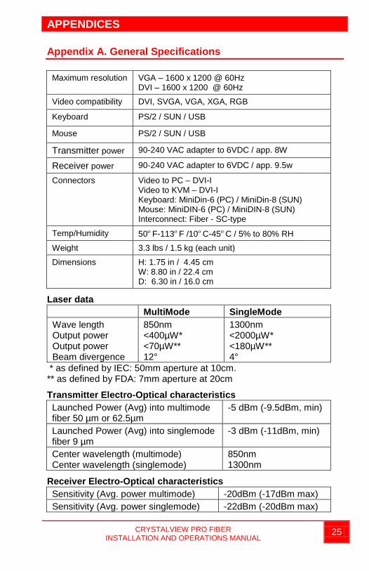
Appendix A. General Specifications
Maximum resolution VGA – 1600 x 1200 @ 60Hz DVI – 1600 x 1200 @ 60Hz
Video compatibility DVI, SVGA, VGA, XGA, RGB
Keyboard PS/2 / SUN / USB
Mouse PS/2 / SUN / USB
Transmitter power 90-240 VAC adapter to 6VDC / app. 8W
Receiver power 90-240 VAC adapter to 6VDC / app. 9.5w
Connectors Video to PC – DVI-I Video to KVM – DVI-I Keyboard: MiniDin-6 (PC) / MiniDin-8 (SUN) Mouse: MiniDIN-6 (PC) / MiniDIN-8 (SUN) Interconnect: Fiber - SC-type
Temp/Humidity 50ο F-113ο F /10ο C-45ο C / 5% to 80% RH
Weight 3.3 lbs / 1.5 kg (each unit)
Dimensions H: 1.75 in / 4.45 cm W: 8.80 in / 22.4 cm D: 6.30 in / 16.0 cm
Laser data MultiMode SingleMode Wave length Output power Output power Beam divergence
850nm <400µW* <70µW** 12°
1300nm <2000µW* <180µW** 4°
* as defined by IEC: 50mm aperture at 10cm. ** as defined by FDA: 7mm aperture at 20cm
Transmitter Electro-Optical characteristics Launched Power (Avg) into multimode fiber 50 µm or 62.5µm
-5 dBm (-9.5dBm, min)
Launched Power (Avg) into singlemode fiber 9 µm
-3 dBm (-11dBm, min)
Center wavelength (multimode) Center wavelength (singlemode)
850nm 1300nm
Receiver Electro-Optical characteristics Sensitivity (Avg. power multimode) -20dBm (-17dBm max) Sensitivity (Avg. power singlemode) -22dBm (-20dBm max)
26 CRYSTALVIEW PRO FIBER INSTALLATION AND OPERATIONS MANUAL
Appendix B. Parts and cables
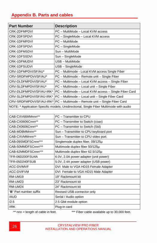
Part Number Description CRK-2DFMPDVI PC – MultiMode – Local KVM access CRK-2DFSPDVI PC – SingleMode – Local KVM access CRK-1DFMPDVI PC – MultiMode CRK-1DFSPDVI PC – SingleMode CRK-1DFMSDVI Sun – MultiMode CRK-1DFSSDVI Sun – SingleMode CRK-1DFMUDVI USB – MultiMode CRK-1DFSUDVI USB – SingleMode CRV-1DFMPDVI/SF/AU* PC – Multimode - Local KVM access Single Fiber CRV-SRDFMPDVI/SF/AU* PC – Multimode – Remote unit – Single Fiber CRV-DLDFMPDVI/SF/AU* PC – Multimode – Local KVM access – Single Fiber CRV-SLDFMPDVI/SF/AU* PC – Multimode – Local unit – Single Fiber CRV-DLDFMPDVI/SF/AU-IRK* PC – Multimode – Local KVM access – Single Fiber Card CRV-SLDFMPDVI/SF/AU-IRK* PC – Multimode – Local unit – Single Fiber Card CRV-SRDFMPDVI/SF/AU-IRK* PC – Multimode – Remote unit – Single Fiber Card NOTE: * Application Specific models, Unidirectional, Single Fiber Multimode with audio CAB-CXV66MMnnn** PC – Transmitter to CPU CAB-CX0606Cnnn** PC – Transmitter to Switch (coax) CAB-ZX0606Cnnn** PC – Transmitter to Switch (Std) CAB-MD8MMnnn** Sun – Transmitter to CPU keyboard port CAB-CXVMMnnn** Sun – Transmitter to CPU video port CAB-09SMDFSCnnn*** Singlemode duplex fiber, 09/125µ CAB-50MMDFSCnnn*** Multimode duplex fiber 50/125µ CAB-62MMDFSCnnn*** Multimode duplex fiber 62.5/125µ TFR-06D200FSU4A 6.0V, 2.0A power adapter (unit power) TFR-05D240FSUB 5.0V, 2.4A power adapter (USB power) ACC-DVIMVF DVI Male to VGA HD15 Female Adapter ACC-DVIFVM DVI Female to VGA HD15 Male Adapter RM-UM19 19” Rackmount kit RM-UM23 23” Rackmount kit RM-UM24 24” Rackmount kit “B” Part number suffix Revised USB connector only /AUD Serial / Audio option /2.5 2.5 Gbit module option /IRK Plug-in card
** nnn = length of cable in feet. *** Fiber cable available up to 30,000 feet.
CRYSTALVIEW PRO FIBER INSTALLATION AND OPERATIONS MANUAL 27
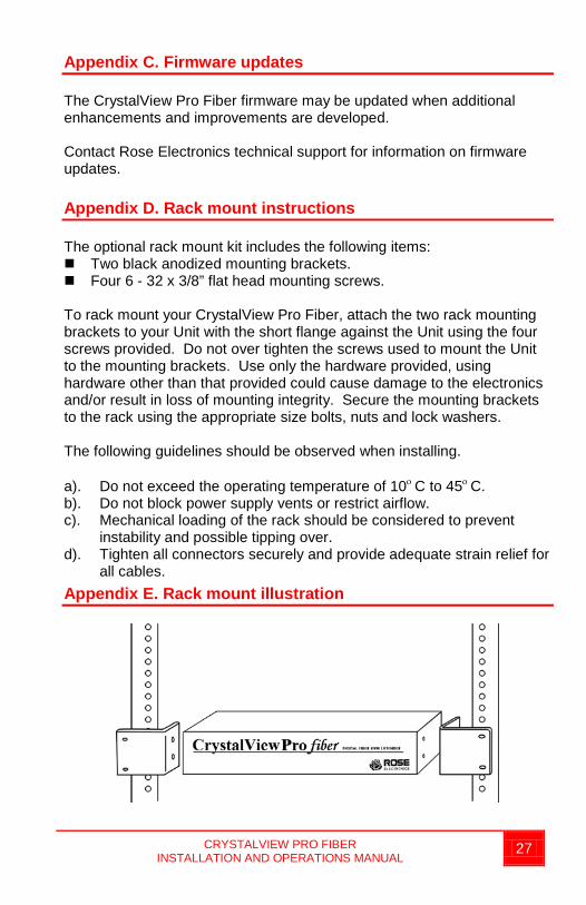
Appendix C. Firmware updates The CrystalView Pro Fiber firmware may be updated when additional enhancements and improvements are developed. Contact Rose Electronics technical support for information on firmware updates. Appendix D. Rack mount instructions The optional rack mount kit includes the following items: Two black anodized mounting brackets. Four 6 - 32 x 3/8” flat head mounting screws. To rack mount your CrystalView Pro Fiber, attach the two rack mounting brackets to your Unit with the short flange against the Unit using the four screws provided. Do not over tighten the screws used to mount the Unit to the mounting brackets. Use only the hardware provided, using hardware other than that provided could cause damage to the electronics and/or result in loss of mounting integrity. Secure the mounting brackets to the rack using the appropriate size bolts, nuts and lock washers. The following guidelines should be observed when installing. a). Do not exceed the operating temperature of 10ο C to 45ο C. b). Do not block power supply vents or restrict airflow. c). Mechanical loading of the rack should be considered to prevent
instability and possible tipping over. d). Tighten all connectors securely and provide adequate strain relief for
all cables. Appendix E. Rack mount illustration
28 CRYSTALVIEW PRO FIBER INSTALLATION AND OPERATIONS MANUAL
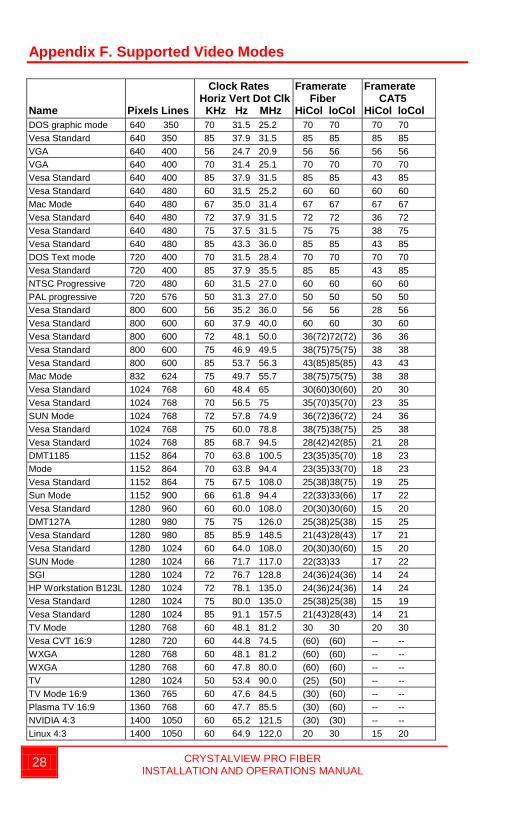
Appendix F. Supported Video Modes Name
Pixels Lines
Clock Rates Horiz Vert Dot Clk KHz Hz MHz
Framerate Fiber HiCol loCol
Framerate CAT5 HiCol loCol
DOS graphic mode 640 350 70 31.5 25.2 70 70 70 70 Vesa Standard 640 350 85 37.9 31.5 85 85 85 85 VGA 640 400 56 24.7 20.9 56 56 56 56 VGA 640 400 70 31.4 25.1 70 70 70 70 Vesa Standard 640 400 85 37.9 31.5 85 85 43 85 Vesa Standard 640 480 60 31.5 25.2 60 60 60 60 Mac Mode 640 480 67 35.0 31.4 67 67 67 67 Vesa Standard 640 480 72 37.9 31.5 72 72 36 72 Vesa Standard 640 480 75 37.5 31.5 75 75 38 75 Vesa Standard 640 480 85 43.3 36.0 85 85 43 85 DOS Text mode 720 400 70 31.5 28.4 70 70 70 70 Vesa Standard 720 400 85 37.9 35.5 85 85 43 85 NTSC Progressive 720 480 60 31.5 27.0 60 60 60 60 PAL progressive 720 576 50 31.3 27.0 50 50 50 50 Vesa Standard 800 600 56 35.2 36.0 56 56 28 56 Vesa Standard 800 600 60 37.9 40.0 60 60 30 60 Vesa Standard 800 600 72 48.1 50.0 36(72)72(72) 36 36 Vesa Standard 800 600 75 46.9 49.5 38(75)75(75) 38 38 Vesa Standard 800 600 85 53.7 56.3 43(85)85(85) 43 43 Mac Mode 832 624 75 49.7 55.7 38(75)75(75) 38 38 Vesa Standard 1024 768 60 48.4 65 30(60)30(60) 20 30 Vesa Standard 1024 768 70 56.5 75 35(70)35(70) 23 35 SUN Mode 1024 768 72 57.8 74.9 36(72)36(72) 24 36 Vesa Standard 1024 768 75 60.0 78.8 38(75)38(75) 25 38 Vesa Standard 1024 768 85 68.7 94.5 28(42)42(85) 21 28 DMT1185 1152 864 70 63.8 100.5 23(35)35(70) 18 23 Mode 1152 864 70 63.8 94.4 23(35)33(70) 18 23 Vesa Standard 1152 864 75 67.5 108.0 25(38)38(75) 19 25 Sun Mode 1152 900 66 61.8 94.4 22(33)33(66) 17 22 Vesa Standard 1280 960 60 60.0 108.0 20(30)30(60) 15 20 DMT127A 1280 980 75 75 126.0 25(38)25(38) 15 25 Vesa Standard 1280 980 85 85.9 148.5 21(43)28(43) 17 21 Vesa Standard 1280 1024 60 64.0 108.0 20(30)30(60) 15 20 SUN Mode 1280 1024 66 71.7 117.0 22(33)33 17 22 SGI 1280 1024 72 76.7 128.8 24(36)24(36) 14 24 HP Workstation B123L 1280 1024 72 78.1 135.0 24(36)24(36) 14 24 Vesa Standard 1280 1024 75 80.0 135.0 25(38)25(38) 15 19 Vesa Standard 1280 1024 85 91.1 157.5 21(43)28(43) 14 21 TV Mode 1280 768 60 48.1 81.2 30 30 20 30 Vesa CVT 16:9 1280 720 60 44.8 74.5 (60) (60) -- -- WXGA 1280 768 60 48.1 81.2 (60) (60) -- -- WXGA 1280 768 60 47.8 80.0 (60) (60) -- -- TV 1280 1024 50 53.4 90.0 (25) (50) -- -- TV Mode 16:9 1360 765 60 47.6 84.5 (30) (60) -- -- Plasma TV 16:9 1360 768 60 47.7 85.5 (30) (60) -- -- NVIDIA 4:3 1400 1050 60 65.2 121.5 (30) (30) -- -- Linux 4:3 1400 1050 60 64.9 122.0 20 30 15 20
CRYSTALVIEW PRO FIBER INSTALLATION AND OPERATIONS MANUAL 29
(Continued) Name
Pixels Lines
Clock Rates Horiz Vert Dot Clk KHz Hz MHz
Framerate Fiber HiCol loCol
Framerate CAT5 HiCol loCol
SGI 1600 1024 72 77.6 158.3 18(36)24(36) 12 18 Vesa Standard 1600 1200 60 75.0 162.0 15(30)20(30) 10 15 TV Mode 16:9 1600 900 60 55.8 118.8 (30) (30) -- -- UXGA genlocked 1600 1200 50 75.0 138.0 (25) (25) -- -- UXGA reduced blank 1600 1200 60 75.0 162.0 (30) (30) -- -- TV Mode 16:10 1680 1050 60 65.3 146.2 (30) (30) -- -- TV Mode 16:9 1920 1080 50 56.4 148.2 -- (25) -- -- TV Mode reduced blank
1920 1080
60 66.6 138.5
-- (30)
-- --
EIA861B 16:9 1920 1080 60 67.5 148.4 -- (30) -- -- WUXGA 1920 1200 60 74.0 154.0 -- (30) -- --
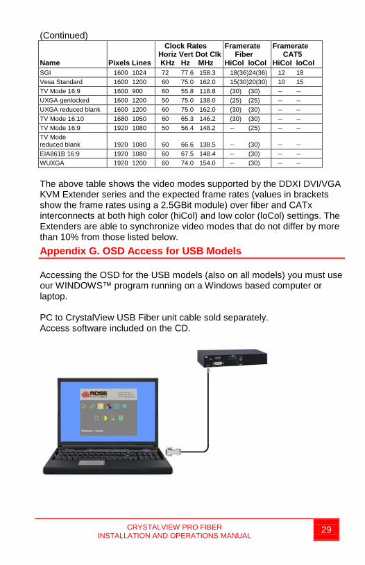
The above table shows the video modes supported by the DDXI DVI/VGA KVM Extender series and the expected frame rates (values in brackets show the frame rates using a 2.5GBit module) over fiber and CATx interconnects at both high color (hiCol) and low color (loCol) settings. The Extenders are able to synchronize video modes that do not differ by more than 10% from those listed below. Appendix G. OSD Access for USB Models Accessing the OSD for the USB models (also on all models) you must use our WINDOWS™ program running on a Windows based computer or laptop. PC to CrystalView USB Fiber unit cable sold separately. Access software included on the CD.

10707 Stancliff Road Phone: (281) 933-7673 Houston, Texas 77099 WWW.ROSE.COM