Embed Size (px)
Citation preview

Sea Tel, Inc. 4030 Nelson Avenue Concord, CA 94520 Tel: (925) 798-7979 Fax: (925) 798-7986 Web: http://www.cobham.com/seatel
Sea Tel Europe Unit 1, Orion Industrial Centre Wide Lane, Swaythling Southampton, UK S0 18 2HJ Tel: 44 (0)23 80 671155 Fax: 44 (0)23 80 671166 Web: http://www.cobham.com/seatel
Sea Tel Inc is also doing business as Cobham SATCOM - Maritime
January 20, 2014 Document. No. 136465 Revision A1
INSTALLATION AND OPERATION MANUAL
FOR SEA TEL MODEL
ST94-21 DUAL C/QUAD KU-BAND TVRO ANTENNA
ii
Sea Tel Marine Stabilized Antenna systems are manufactured in the United States of America.
Sea Tel is an ISO 9001:2008 registered company.
Certificate Number 13690 issued March 14, 2011.
R&TTE
CE
The Series 97 Family of Marine Stabilized Antenna Pedestals with DAC-97 Antenna Control Unit complied with the requirements of European Norms and European Standards EN 60945 (1997) and prETS 300 339 (1998-03) on July 20, 1999. Sea Tel document number 119360 European Union Declaration of Conformity for Marine Navigational Equipment is available on request.
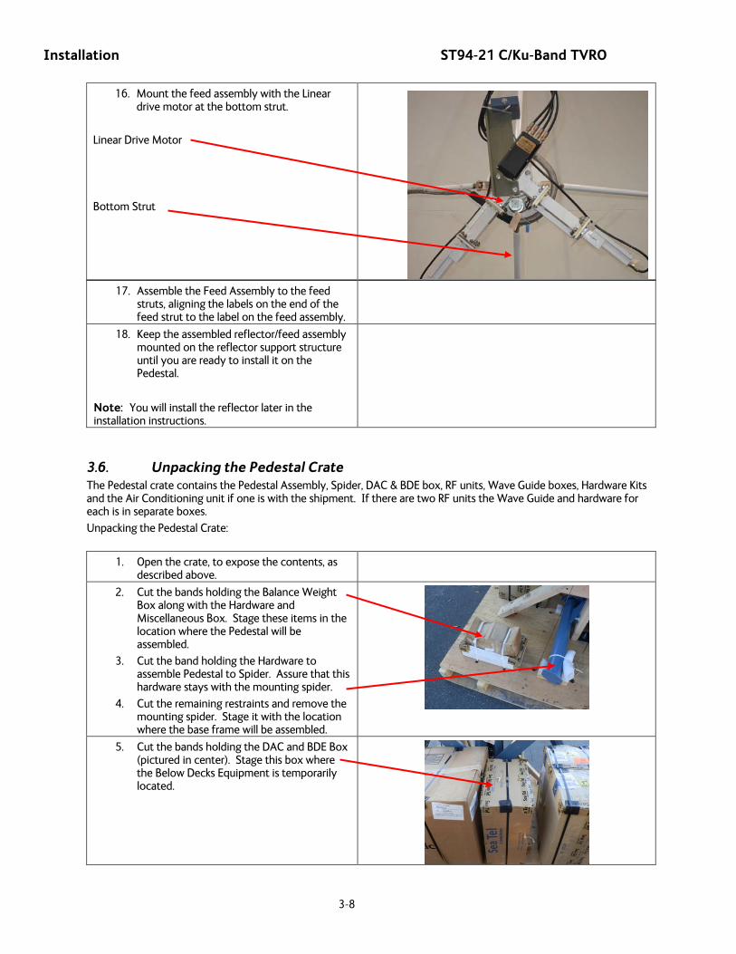
Copyright Notice
Copyright © 2012 Sea Tel Inc All Rights Reserved. The information contained in this document is proprietary to Sea Tel, Inc.. This document may not be reproduced or distributed in any form without prior written consent of Sea Tel, Inc. The information in this document is subject to change without notice. Sea Tel Inc, is also doing business as Cobham Antenna Systems.
This document has been registered with the U.S. Copyright Office.
iii
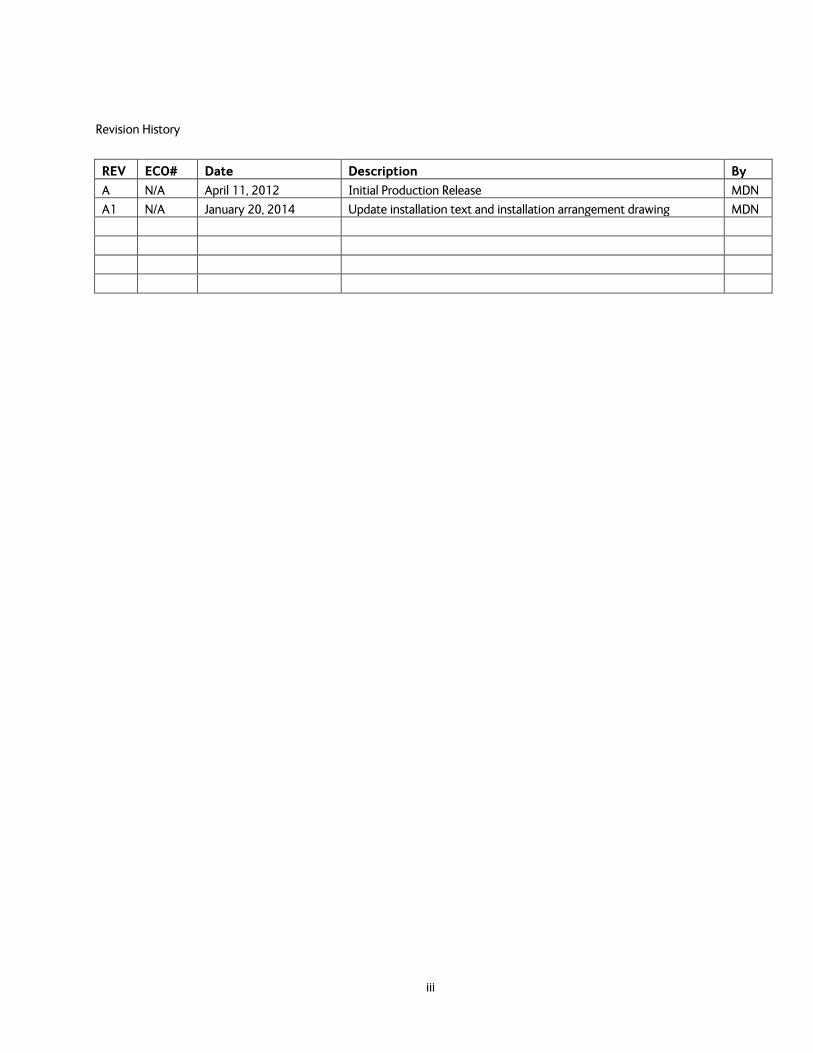
Revision History
REV ECO# Date Description By
A N/A April 11, 2012 Initial Production Release MDN
A1 N/A January 20, 2014 Update installation text and installation arrangement drawing MDN


Table of Contents
v
1. INTRODUCTION .......................................................................................................................................................................................... 1-1 1.1. GENERAL DESCRIPTION OF SYSTEM ........................................................................................................................................................... 1-1 1.2. PURPOSE .......................................................................................................................................................................................................... 1-1 1.3. SYSTEM COMPONENTS ................................................................................................................................................................................. 1-1 1.4. DUAL ANTENNA CONFIGURATION ............................................................................................................................................................. 1-2 1.5. DUAL ANTENNA ARBITRATOR ..................................................................................................................................................................... 1-3 1.6. GENERAL SCOPE OF THIS MANUAL .............................................................................................................................................................. 1-3 1.7. QUICK OVERVIEW OF CONTENTS ................................................................................................................................................................ 1-3
2. SITE SURVEY .................................................................................................................................................................................................. 2-1 2.1. SITE SELECTION ABOARD THE SHIP .......................................................................................................................................................... 2-1 2.2. ANTENNA SHADOWING (BLOCKAGE) AND RF INTERFERENCE .............................................................................................................. 2-1 2.3. MOUNTING FOUNDATION ........................................................................................................................................................................... 2-2
2.3.1. Mounting on Deck or Deckhouse ...................................................................................................................................... 2-2 2.3.2. ADE Mounting Considerations ........................................................................................................................................... 2-2 2.3.3. Sizing of the support pedestal ............................................................................................................................................ 2-2
2.4. MOUNTING HEIGHT AND FORE-AFT LOCATION ..................................................................................................................................... 2-3 2.5. MAST CONFIGURATIONS ............................................................................................................................................................................. 2-4
2.5.1. Vertical Masts .............................................................................................................................................................................. 2-4 2.5.2. Raked Masts .................................................................................................................................................................................. 2-4 2.5.3. Girder Masts ................................................................................................................................................................................. 2-5 2.5.4. Truss Mast ..................................................................................................................................................................................... 2-5
2.6. SAFE ACCESS TO THE ADE .......................................................................................................................................................................... 2-5 2.7. BELOW DECKS EQUIPMENT LOCATION ..................................................................................................................................................... 2-5 2.8. CABLES ............................................................................................................................................................................................................. 2-6
2.8.1. ADE/BDE Coaxial Cables ........................................................................................................................................................ 2-6 2.8.2. Antenna Power Cable .............................................................................................................................................................. 2-6 2.8.3. Air Conditioner Power Cable ............................................................................................................................................... 2-6 2.8.4. ACU Power Cable/Outlet ........................................................................................................................................................ 2-7 2.8.5. Gyro Compass Cable ................................................................................................................................................................ 2-7 2.8.6. Grounding ...................................................................................................................................................................................... 2-7
3. INSTALLATION ............................................................................................................................................................................................. 3-1 3.1. GENERAL CAUTIONS & WARNINGS ........................................................................................................................................................... 3-1 3.2. SITE SELECTION ABOARD SHIP ................................................................................................................................................................... 3-2 3.3. PREPARATION ................................................................................................................................................................................................. 3-2 3.4. OPENING YOUR CRATES ................................................................................................................................................................................ 3-2
3.4.1. Location of Items inside the Crates ................................................................................................................................. 3-3 3.4.2. Base Frame and Reflector Crate ........................................................................................................................................ 3-3 3.4.3. Pedestal Crate ............................................................................................................................................................................. 3-4 3.4.4. Radome Crate: ............................................................................................................................................................................. 3-5
3.5. UNPACKING THE BASE FRAME AND REFLECTOR CRATE ......................................................................................................................... 3-5 3.6. UNPACKING THE PEDESTAL CRATE ............................................................................................................................................................ 3-8 3.7. UNPACKING THE RADOME CRATE: ........................................................................................................................................................... 3-10 3.8. ASSEMBLING THE ADE ............................................................................................................................................................................... 3-11
3.8.1. Preparing for Assembly of the ADE .............................................................................................................................. 3-11 3.8.2. Sub-assemble the Base Frame Assembly ................................................................................................................... 3-11 3.8.3. Sub-assemble the bottom panels of the 144” Radome Assembly ................................................................ 3-12 3.8.4. Sub-assemble the upper panels of the 144” Radome Assembly ................................................................... 3-16
Table of Contents
vi
3.8.5. Sub-assemble the bottom panels onto the base frame ..................................................................................... 3-20 3.8.6. Sub-assemble the Antenna Pedestal ........................................................................................................................... 3-21 3.8.7. Close the 144” Radome Assembly ................................................................................................................................ 3-23
3.9. INSTALLING THE ADE ................................................................................................................................................................................ 3-24 3.9.1. Hoist .............................................................................................................................................................................................. 3-24 3.9.2. Install Antenna/Radome/Baseframe ............................................................................................................................ 3-25
3.10. INSTALLING THE BELOW DECKS EQUIPMENT. ....................................................................................................................................... 3-25 3.10.1. General Cautions & Warnings .......................................................................................................................................... 3-25 3.10.2. Preparing BDE Location ...................................................................................................................................................... 3-25 3.10.3. Installing the Below Deck Equipment ......................................................................................................................... 3-25
3.11. CONNECTING THE BELOW DECKS EQUIPMENT ..................................................................................................................................... 3-25 3.11.1. Connecting the ADE AC Power Cable ......................................................................................................................... 3-26 3.11.2. Connecting the BDE AC Power Cables ....................................................................................................................... 3-26 3.11.3. Connecting the ADE IF Coaxes ...................................................................................................................................... 3-26 3.11.4. Antenna Control Unit Connections .............................................................................................................................. 3-26 3.11.5. 13Terminal Mounting Strip (TMS) Connections .................................................................................................... 3-26 3.11.6. Other BDE connections ...................................................................................................................................................... 3-27
3.12. FINAL CHECKS.............................................................................................................................................................................................. 3-27 3.12.1. Visual/Electrical inspection ............................................................................................................................................... 3-27 3.12.2. Electrical - Double check wiring connections ......................................................................................................... 3-27
3.13. POWER-UP ................................................................................................................................................................................................... 3-28 3.14. CABLE TERMINATIONS ............................................................................................................................................................................... 3-28
3.14.1. At The Radome ........................................................................................................................................................................ 3-28 3.14.2. ACU & TMS ................................................................................................................................................................................ 3-28 3.14.3. Other BDE Equipment ......................................................................................................................................................... 3-28
3.15. FINAL ASSEMBLY ......................................................................................................................................................................................... 3-28 3.15.1. Remove Stow Braces/Restraints ..................................................................................................................................... 3-28 3.15.2. Verify all assembly and Wiring connections ............................................................................................................ 3-28
3.16. POWER-UP THE ADE ................................................................................................................................................................................. 3-28 3.16.1. Initialization .............................................................................................................................................................................. 3-28 3.16.2. Home Flag Position ............................................................................................................................................................... 3-29 3.16.3. BDE ................................................................................................................................................................................................ 3-29 3.16.4. Balancing the Antenna ........................................................................................................................................................ 3-29 3.16.5. Fine Balance and Monitoring Motor Drive Torque .............................................................................................. 3-29
3.17. SETUP ............................................................................................................................................................................................................ 3-31 4. BASIC SETUP OF THE ACU .................................................................................................................................................................. 4-1
4.1. OPERATOR SETTINGS ..................................................................................................................................................................................... 4-1 4.2. SETUP PARAMETER DISPLAY AND ENTRY MENUS. .................................................................................................................................. 4-1 4.3. TRACK DISP ................................................................................................................................................................................................. 4-1 4.4. ACU FACTORY DEFAULT PARAMETER SETTINGS – STXXX-21 SERIES ANTENNAS ....................................................................... 4-2
5. SETUP – SHIPS GYRO COMPASS ...................................................................................................................................................... 5-1 5.1. GYRO TYPE ................................................................................................................................................................................................... 5-1 5.2. UPDATING THE GYRO TYPE PARAMETER ................................................................................................................................................ 5-1 5.3. IF THERE IS NO SHIPS GYRO COMPASS .................................................................................................................................................... 5-1
6. DETERMINE INTERNAL TRACKING RECEIVER SETTINGS ............................................................................................ 6-1 6.1. IF TRACKING FREQUENCY ............................................................................................................................................................................ 6-1 6.2. BAUD RATE ...................................................................................................................................................................................................... 6-1
Table of Contents
vii
6.3. FEC .................................................................................................................................................................................................................. 6-2 6.3.1. DVB Receiver ................................................................................................................................................................................ 6-2
6.4. TONE ................................................................................................................................................................................................................ 6-2 6.4.1. TVRO Applications ..................................................................................................................................................................... 6-2
6.5. VOLT ................................................................................................................................................................................................................. 6-2 6.5.1. TVRO Application ....................................................................................................................................................................... 6-2
6.6. NID .................................................................................................................................................................................................................. 6-3 7. SETUP – HOME FLAG OFFSET ............................................................................................................................................................. 7-1
7.1. ELECTRONIC CALIBRATION OF RELATIVE ANTENNA POSITION (HOME FLAG OFFSET) ................................................................... 7-1 7.1.1. You Found a Large AZ TRIM value: .................................................................................................................................. 7-1 7.1.2. You Observe “Home” Pointing is LEFT of the Bow-line: ......................................................................................... 7-2 7.1.3. You Observe “Home” Pointing is RIGHT of the Bow-line: ..................................................................................... 7-2 7.1.4. To Enter the HFO value in the DAC_2202: ................................................................................................................... 7-3
8. SETUP – TARGETING ................................................................................................................................................................................ 8-1 8.1. AUTO TRIM ................................................................................................................................................................................................. 8-1 8.2. MANUALLY OPTIMIZING TARGETING ........................................................................................................................................................ 8-1 8.3. EL TRIM ......................................................................................................................................................................................................... 8-2 8.4. AZ TRIM ........................................................................................................................................................................................................ 8-2 8.5. SAVE NEW PARAMETERS ..................................................................................................................................................................... 8-2
9. SETUP – SEARCHING ................................................................................................................................................................................ 9-1 9.1. SEARCHING OPERATION ............................................................................................................................................................................... 9-1
9.1.1. Default Standard (Box) Search Pattern .......................................................................................................................... 9-1 9.1.2. Inclined Orbit Search Pattern ............................................................................................................................................. 9-2 9.1.3. No Gyro Search Pattern ......................................................................................................................................................... 9-3
9.2. CHANGING THE SEARCH PARAMETERS ...................................................................................................................................................... 9-4 9.2.1. AUTO THRES ................................................................................................................................................................................ 9-4 9.2.2. EL STEP SIZE ............................................................................................................................................................................... 9-4 9.2.3. AZ STEP SIZE .............................................................................................................................................................................. 9-4 9.2.4. STEP INTEGRAL .......................................................................................................................................................................... 9-4 9.2.5. SEARCH INC ................................................................................................................................................................................. 9-5 9.2.6. SEARCH LIMIT ............................................................................................................................................................................ 9-5 9.2.7. SEARCH DELAY ........................................................................................................................................................................... 9-5 9.2.8. SWEEP INC ................................................................................................................................................................................... 9-5
9.3. SAVE NEW PARAMETERS ..................................................................................................................................................................... 9-5 10. SETUP – BLOCKAGE & RF RADIATION HAZARD ZONES .............................................................................................. 10-1
10.1. RADIATION HAZARD AND BLOCKAGE MAPPING (AZ LIMIT PARAMETERS) ................................................................................... 10-1 11. SETUP ............................................................................................................................................................................................................... 11-1
11.1. OPERATOR SETTINGS .................................................................................................................................................................................. 11-1 11.2. OPTIMIZING TARGETING (AUTO TRIM) ................................................................................................................................................. 11-1 11.3. OPTIMIZING TARGETING (MANUALLY) ................................................................................................................................................... 11-1 11.4. RADIATION HAZARD AND BLOCKAGE MAPPING (AZ LIMIT PARAMETERS) ................................................................................... 11-1 11.5. TX POLARITY SETUP ................................................................................................................................................................................... 11-2 11.6. TRACK DISP ............................................................................................................................................................................................... 11-2
12. FUNCTIONAL TESTING ....................................................................................................................................................................... 12-1 12.1. ACU / ANTENNA SYSTEM CHECK ............................................................................................................................................................ 12-1 12.2. LATITUDE/LONGITUDE AUTO-UPDATE CHECK ...................................................................................................................................... 12-1 12.3. SHIP HEADING – GYRO COMPASS FOLLOWING CHECK ....................................................................................................................... 12-1
Table of Contents
viii
12.4. AZIMUTH & ELEVATION DRIVE ................................................................................................................................................................ 12-1 12.5. FOUR QUADRANT TRACKING TEST .......................................................................................................................................................... 12-1 12.6. BLOCKAGE SIMULATION TEST .................................................................................................................................................................. 12-2
13. MAINTENANCE AND TROUBLESHOOTING ........................................................................................................................... 13-1 13.1. WARRANTY INFORMATION ....................................................................................................................................................................... 13-1 13.2. RECOMMENDED PREVENTIVE MAINTENANCE ....................................................................................................................................... 13-1
13.2.1. Check ACU Parameters ....................................................................................................................................................... 13-1 13.2.2. Latitude/Longitude Auto-Update check ..................................................................................................................... 13-1 13.2.3. Heading Following ................................................................................................................................................................. 13-1 13.2.4. Azimuth & Elevation Drive ................................................................................................................................................. 13-2 13.2.5. Test Tracking ............................................................................................................................................................................ 13-2 13.2.6. Visual Inspection - Radome & Pedestal ................................................................................................................... 13-2 13.2.7. Mechanical Checks ................................................................................................................................................................ 13-2 13.2.8. Check Balance .......................................................................................................................................................................... 13-2 13.2.9. Observe Antenna Initialization ....................................................................................................................................... 13-2
13.3. 400MHZ MODEM CONFIGURATION ..................................................................................................................................................... 13-3 13.4. 400 MHZ LED INDICATORS .................................................................................................................................................................... 13-4 13.5. 400 MHZ MODEM SIGNALS .................................................................................................................................................................... 13-4
13.5.1. Pedestal M&C ........................................................................................................................................................................... 13-4 13.5.2. Radio M&C ................................................................................................................................................................................. 13-5 13.5.3. Channel Identification ........................................................................................................................................................ 13-5
13.6. TROUBLESHOOTING 400MHZ MODEM COMMUNICATION FAULTS ............................................................................................... 13-6 13.6.1. 400MHz Modem Queries: .................................................................................................................................................. 13-6 13.6.2. Modem Query Methods ..................................................................................................................................................... 13-6 13.6.3. Isolating a 400 MHz Modem Fault Procedure: ...................................................................................................... 13-8
13.7. TROUBLESHOOTING ................................................................................................................................................................................. 13-11 13.7.1. Theory Of Stabilization Operation .............................................................................................................................. 13-11 13.7.2. ST-21 Series Dual C-Band OR Quad Ku-Band TVRO RF Flow ..................................................................... 13-11 13.7.3. Antenna Initialization (ST-21 Series) ......................................................................................................................... 13-12 13.7.4. Troubleshooting using DacRemP ................................................................................................................................ 13-13 13.7.5. Antenna Loop Error Monitoring ................................................................................................................................... 13-14 13.7.6. Reference Sensor Monitoring ........................................................................................................................................ 13-15 13.7.7. Open Loop Rate Sensor Monitoring ........................................................................................................................... 13-16 13.7.8. Open Loop Motor Test ...................................................................................................................................................... 13-17 13.7.9. To Disable/Enable DishScan® ....................................................................................................................................... 13-18 13.7.10. Satellite Reference Mode ................................................................................................................................................. 13-18 13.7.11. To Read/Decode an ACU Error Code 0008 (Pedestal Function Error): ................................................... 13-18 13.7.12. Remote GPS LAT/LON Position: .................................................................................................................................... 13-21
13.8. MAINTENANCE ......................................................................................................................................................................................... 13-22 13.8.1. Balancing the Antenna ...................................................................................................................................................... 13-22 13.8.2. To Adjust Tilt: .......................................................................................................................................................................... 13-23 13.8.3. To Reset/Reinitialize the Antenna: .............................................................................................................................. 13-24
13.9. PEDESTAL CONTROL UNIT CONFIGURATION - STXXX-21 SERIES ............................................................................................... 13-25 13.9.1. To configure the PCU; ........................................................................................................................................................ 13-25 13.9.2. MODEL CONFIGURATION NUMBERS ...................................................................................................................... 13-25
13.10. ANTENNA STOWING PROCEDURE ......................................................................................................................................................... 13-26 14. ST94-21 TECHNICAL SPECIFICATIONS .................................................................................................................................. 14-1
14.1. 9497 ANTENNA REFLECTOR .................................................................................................................................................................... 14-1

Table of Contents
ix
14.2. FEED ASSEMBLIES ........................................................................................................................................................................................ 14-1 14.2.1. TVRO-21 Dual C-Band / Quad Ku-Band Feed Assembly .................................................................................... 14-1
14.3. STABILIZED ANTENNA PEDESTAL ASSEMBLY ......................................................................................................................................... 14-2 14.4. MK 2 PEDESTAL CONTROL UNIT (PCU) ............................................................................................................................................... 14-3 14.5. MK 2 MOTOR DRIVER ENCLOSURE (MDE) .......................................................................................................................................... 14-3 14.6. 400 MHZ BASE & PEDESTAL UNLIMITED AZIMUTH MODEMS (3 CHANNEL) ............................................................................... 14-4 14.7. 126” RADOME ASSEMBLY ......................................................................................................................................................................... 14-4 14.8. ENVIRONMENTAL CONDITIONS (ADE) ................................................................................................................................................... 14-5 14.9. CABLES ........................................................................................................................................................................................................... 14-5
14.9.1. Antenna Control Cable (Provided from ACU-MUX) .............................................................................................. 14-5 14.9.2. Antenna L-Band TVRO IF Coax Cables (Customer Furnished) ....................................................................... 14-5 14.9.3. AC Power Cable (Pedestal & Rf Equipment) ............................................................................................................. 14-5 14.9.4. Gyro Compass Interface Cable (Customer Furnished) ...................................................................................... 14-6 14.9.5. Fiber Optic Transmitter (CFE Optional) ...................................................................................................................... 14-6
15. MODEL ST94-21 DRAWINGS ............................................................................................................................................................ 15-1 15.1. MODEL ST94-21 SPECIFIC DRAWINGS ................................................................................................................................................ 15-1 15.2. STXXX-21 GENERAL DRAWINGS .............................................................................................................................................................. 15-1

Table of Contents
x
This Page Intentionally Left Blank

ST94-21 C/Ku-Band TVRO Introduction
1-1
1. Introduction
1.1. General Description of system Your Series 00 system is a fully stabilized antenna that has been designed and manufactured so as to be inherently reliable, easy to maintain, and simple to operate. Except for start-ups, or when changing to operate with different transponders or satellites, the equipment essentially permits unattended operation.
1.2. Purpose This shipboard Television Receive Only (TVRO) system provides you with satellite TV programming while in port or underway. Your Antenna system will receive signals of adequately high E.I.R.P. levels (see the Specifications section of this manual), in linear or circular polarization mode from any of the geosynchronous TV satellites at C-Band or Ku-band frequencies (dependent upon currently installed feed assembly). This input will be distributed to all of your satellite TV receivers which will provide the Audio/Video to your Televisions. Many satellites also provide CD quality audio programming which may also be routed to your stereo equipment.
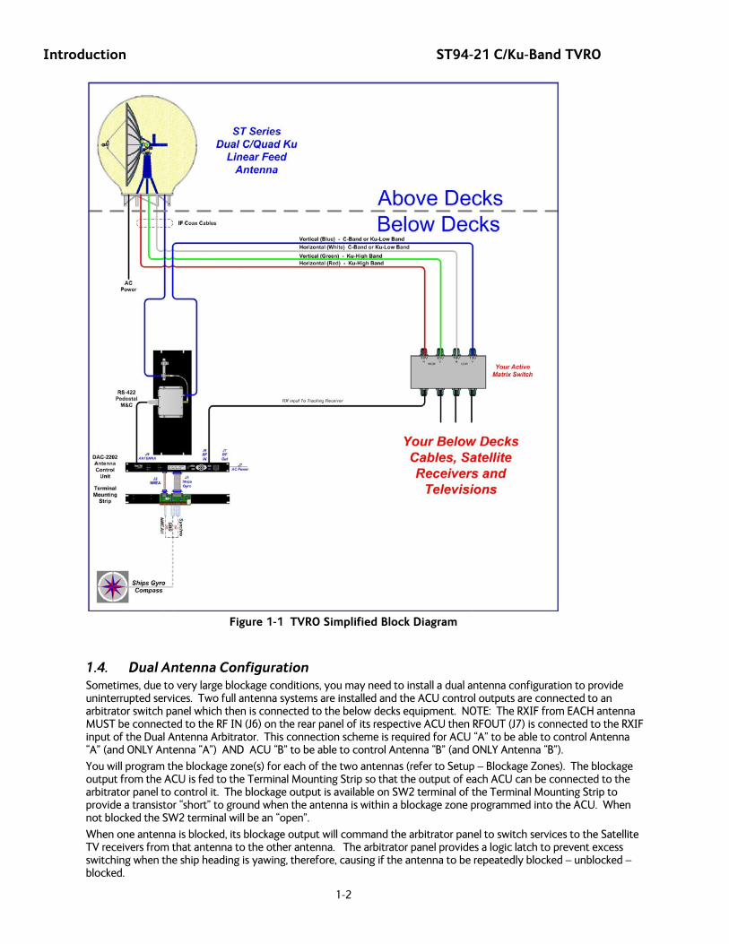
1.3. System Components Your TVRO Antenna system consists of two major groups of equipment; an above-decks group and a below-decks group. Each group is comprised of, but is not limited to, the items listed below. All equipment comprising the Above Decks is incorporated inside the radome assembly and is integrated into a single operational entity. For inputs, this system requires only an unobstructed line-of-sight view to the satellite, Gyro Compass input and AC electrical power. Video and Audio outputs from your satellite receivers are available for distribution and monitoring.
For more information about these components, refer to the Basic System Information section of this manual.
A. Above-Decks Equipment (ADE) Group
1. Stabilized antenna pedestal
2. Antenna Reflector
3. Feed Assembly with LNB(s)
4. Radome Assembly
B. Below-Decks Equipment Group
5. Antenna Control Unit
6. 2 or 4 input Matrix Switch with desired number of outputs (one output to the ACU plus enough outputs for the installed satellite receivers).
7. Satellite Video Receiver(s) & Television(s)
8. Control, RF and Video cables
Introduction ST94-21 C/Ku-Band TVRO
1-2
Figure 1-1 TVRO Simplified Block Diagram
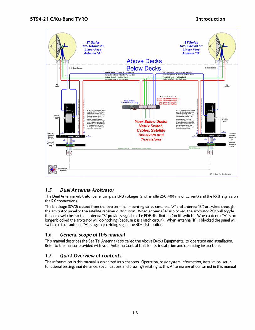
1.4. Dual Antenna Configuration Sometimes, due to very large blockage conditions, you may need to install a dual antenna configuration to provide uninterrupted services. Two full antenna systems are installed and the ACU control outputs are connected to an arbitrator switch panel which then is connected to the below decks equipment. NOTE: The RXIF from EACH antenna MUST be connected to the RF IN (J6) on the rear panel of its respective ACU then RFOUT (J7) is connected to the RXIF input of the Dual Antenna Arbitrator. This connection scheme is required for ACU “A” to be able to control Antenna “A” (and ONLY Antenna “A”) AND ACU “B” to be able to control Antenna “B” (and ONLY Antenna “B”).
You will program the blockage zone(s) for each of the two antennas (refer to Setup – Blockage Zones). The blockage output from the ACU is fed to the Terminal Mounting Strip so that the output of each ACU can be connected to the arbitrator panel to control it. The blockage output is available on SW2 terminal of the Terminal Mounting Strip to provide a transistor “short” to ground when the antenna is within a blockage zone programmed into the ACU. When not blocked the SW2 terminal will be an “open”.
When one antenna is blocked, its blockage output will command the arbitrator panel to switch services to the Satellite TV receivers from that antenna to the other antenna. The arbitrator panel provides a logic latch to prevent excess switching when the ship heading is yawing, therefore, causing if the antenna to be repeatedly blocked – unblocked – blocked.
ST94-21 C/Ku-Band TVRO Introduction
1-3
1.5. Dual Antenna Arbitrator The Dual Antenna Arbitrator panel can pass LNB voltages (and handle 250-400 ma of current) and the RXIF signals on the RX connections.
The blockage (SW2) output from the two terminal mounting strips (antenna “A” and antenna “B”) are wired through the arbitrator panel to the satellite receiver distribution. When antenna “A” is blocked, the arbitrator PCB will toggle the coax switches so that antenna “B” provides signal to the BDE distribution (multi-switch). When antenna “A” is no longer blocked the arbitrator will do nothing (because it is a latch circuit). When antenna “B” is blocked the panel will switch so that antenna “A” is again providing signal the BDE distribution.
1.6. General scope of this manual This manual describes the Sea Tel Antenna (also called the Above Decks Equipment), its’ operation and installation. Refer to the manual provided with your Antenna Control Unit for its’ installation and operating instructions.
1.7. Quick Overview of contents The information in this manual is organized into chapters. Operation, basic system information, installation, setup, functional testing, maintenance, specifications and drawings relating to this Antenna are all contained in this manual

Introduction ST94-21 C/Ku-Band TVRO
1-4
This Page Intentionally Left Blank
ST94-21 C/Ku-Band TVRO Site Survey
2-1
2. Site Survey The objective of the Site survey is to find the best place to mount the antenna & the below decks equipment, the length and routing of the cables and any other items or materials that are required to install the system and identify any other issues that must be resolved before or during the installation.
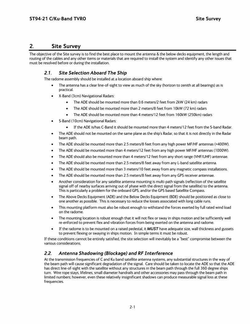
2.1. Site Selection Aboard The Ship The radome assembly should be installed at a location aboard ship where:
• The antenna has a clear line-of-sight to view as much of the sky (horizon to zenith at all bearings) as is practical.
• X-Band (3cm) Navigational Radars:
• The ADE should be mounted more than 0.6 meters/2 feet from 2kW (24 km) radars
• The ADE should be mounted more than 2 meters/8 feet from 10kW (72 km) radars
• The ADE should be mounted more than 4 meters/12 feet from 160kW (250km) radars
• S-Band (10cm) Navigational Radars:
• If the ADE is/has C-Band it should be mounted more than 4 meters/12 feet from the S-band Radar.
• The ADE should not be mounted on the same plane as the ship's Radar, so that it is not directly in the Radar beam path.
• The ADE should be mounted more than 2.5 meters/8 feet from any high power MF/HF antennas (<400W).
• The ADE should be mounted more than 4 meters/12 feet from any high power MF/HF antennas (1000W).
• The ADE should also be mounted more than 4 meters/12 feet from any short range (VHF/UHF) antennae.
• The ADE should be mounted more than 2.5 meters/8 feet away from any L-band satellite antenna.
• The ADE should be mounted more than 3 meters/10 feet away from any magnetic compass installations.
• The ADE should be mounted more than 2.5 meters/8 feet away from any GPS receiver antennae.
• Another consideration for any satellite antenna mounting is multi-path signals (reflection of the satellite signal off of nearby surfaces arriving out of phase with the direct signal from the satellite) to the antenna. This is particularly a problem for the onboard GPS, and/or the GPS based Satellite Compass.
• The Above Decks Equipment (ADE) and the Below Decks Equipment (BDE) should be positioned as close to one another as possible. This is necessary to reduce the losses associated with long cable runs.
• This mounting platform must also be robust enough to withstand the forces exerted by full rated wind load on the radome.
• The mounting location is robust enough that it will not flex or sway in ships motion and be sufficiently well re-enforced to prevent flex and vibration forces from being exerted on the antenna and radome.
• If the radome is to be mounted on a raised pedestal, it MUST have adequate size, wall thickness and gussets to prevent flexing or swaying in ships motion. In simple terms it must be robust.
If these conditions cannot be entirely satisfied, the site selection will inevitably be a “best” compromise between the various considerations.
2.2. Antenna Shadowing (Blockage) and RF Interference At the transmission frequencies of C and Ku band satellite antenna systems, any substantial structures in the way of the beam path will cause significant degradation of the signal. Care should be taken to locate the ADE so that the ADE has direct line-of-sight with the satellite without any structures in the beam path through the full 360 degree ships turn. Wire rope stays, lifelines, small diameter handrails and other accessories may pass through the beam path in limited numbers; however, even these relatively insignificant shadows can produce measurable signal loss at these frequencies.
Site Survey ST94-21 C/Ku-Band TVRO
2-2
2.3. Mounting Foundation
2.3.1. Mounting on Deck or Deckhouse While mounting the ADE on a mast is a common solution to elevate the ADE far enough above the various obstructions which create signal blockages, sometimes the best mounting position is on a deck or deckhouse top. These installations are inherently stiffer than a mast installation, if for no other reason than the design of the deck/deckhouse structure is prescribed by the ship’s classification society. In the deck/deckhouse design rules, the minimum plating and stiffener guidelines are chosen to preclude high local vibration amplitudes.
Most installations will have a base frame with multiple attachment points around the perimeter of the base frame to mount the Above Deck Equipment (ADE) onto a deck or deckhouse structure of the ship. The base frame may be mounted using the supplied legs & braces to raise the ADE above the deck for radome hatch access allow access into the radome. The base frame may be directly attached to the deck, in which case the access panel in the floor of the base frame cannot be utilized. In this case the installation must allow acces into the radome through a door in one of the side panels or an access opening directly under the hacth. Some care must be taken to ensure the mounting pedestal is properly aligned with the stiffeners under the deck plating.
Alternately, a specifically designed and stiffened mast may be used to mount the base frame above the deck; this should only be attempted if sufficient deck space high on the ship is not available.
2.3.2. ADE Mounting Considerations Mounting the radome directly on the deck, or platform prevents access to the hatch in the base of the radome unless an opening is designed into the mounting surface to allow such entry. If there is no access to the hatch the only way to service the antenna is to remove the radome top.
Ladder rungs must be provided on all mounting stanchions greater than 3-4 feet tall to allow footing for personnel safety when entering the hatch of the radome.
The recommended cable passage is through the bottom (near center) of the radome base, down through the ADE support pedestal (if used), through the deck and into the interior of the ship.
2.3.3. Sizing of the support pedestal The following should be taken into account when choosing the height of a mounting support stand:
1. The height of the pedestal should be kept as short as possible, taking into account recommendations given in other Sea Tel Guidelines.
2. The minimum height of the pedestal above a flat deck or platform to allow access into the radome for maintenance should be 0.6 meters (24 inches).
3. The connection of the ADE mounting plate to the stanchion and the connection of the pedestal to the ship should be properly braced with triangular gussets (see graphic above). Care should be taken to align the pedestal gussets to the ship’s stiffeners as much as possible. Doublers or other reinforcing plates should be considered to distribute the forces when under-deck stiffeners are inadequate.
4. The diameter of the pedestal stanchion shall not be smaller than 100 millimeters (4 inches). Where the ADE base diameter exceeds 1.5 meters (60 inches), additional stanchions (quantity greater than 3) should be placed rather than a single large stanchion.
5. Shear and bending should be taken into account in sizing the ADE mounting plate and associated gussets.
6. Shear and bending must be taken into account when sizing the pedestal to ship connection.
7. All welding should be full penetration welds –V-groove welds with additional fillet welds – with throats equivalent to the thickness of the thinnest base material.
8. For an ADE mounted greater than 0.6 meters (24 inches) above the ship’s structure, at least one (1) foot rung should be added. Additional rungs should be added for every 0.3 meter (12 inches) of pedestal height above the ship’s structure.
9. For an ADE mounted greater than 3 meters (9 feet) above the ship’s structure, a fully enclosing cage should be included in way of the access ladder, starting 2.3 meters (7 feet) above the ship’s structure.
ST94-21 C/Ku-Band TVRO Site Survey
2-3
2.4. Mounting Height and Fore-Aft Location Installations with mast or deck vibrations at frequencies between 2 and 15 Hertz have been identified by Sea Tel as causing problems with the isolation systems of the ADE. Preventing problems prior to installation due to these vibrations is one of the primary considerations in choosing where to mount the antenna.
In some installations, though, the combination of mounting height, fore-aft location and ship motion can impart significant accelerations on the entire ADE. Installations where the ADE is situated high on the ship – usually at the top of a mast – places the ADE is a position where the low frequency ship motion in roll and/or pitch creates two accelerations – tangential and radial. These accelerations vary in a periodic function, out-of-phase from the ship response to the wave motions.
Radial acceleration is the acceleration acting on the mass of the ADE pulling away from the center of the axis (roll or pitch). In this sense, it would be a force trying to ‘pull’ the ADE away from the ship. We normally are not too concerned with radial acceleration, since it must become far greater than gravity to have a detrimental effect on the ADE.
Tangential acceleration is the acceleration acting on the mass of the ADE pulling across the center of the axis (roll or pitch). This acceleration becomes a force trying to pull the ADE to the side. The tangential acceleration has an effect on both the strength of the ADE pedestal and the tracking accuracy of the control algorithm.
The effect of tangential acceleration is felt by the structure of the ADE before it truly affects the tracking accuracy. For instance, Sea Tel normally accepts that a tracking error of 0.1 degrees RMS at 0.5 G to be within acceptable error margins. A 0.5 G tangential acceleration on the ADE means that ½ of the weight of the ADE is acting sideways on the pedestal structure.
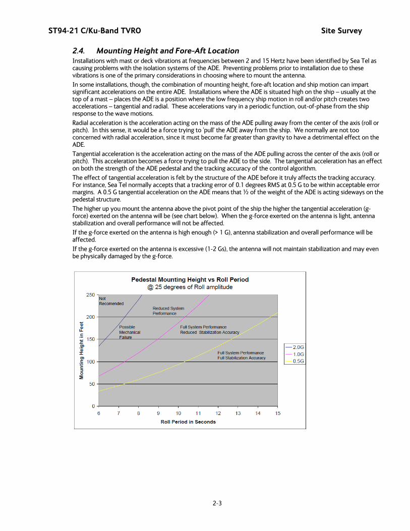
The higher up you mount the antenna above the pivot point of the ship the higher the tangential acceleration (g-force) exerted on the antenna will be (see chart below). When the g-force exerted on the antenna is light, antenna stabilization and overall performance will not be affected.
If the g-force exerted on the antenna is high enough (> 1 G), antenna stabilization and overall performance will be affected.
If the g-force exerted on the antenna is excessive (1-2 Gs), the antenna will not maintain stabilization and may even be physically damaged by the g-force.
Site Survey ST94-21 C/Ku-Band TVRO
2-4
2.5. Mast Configurations Sea Tel recommends the ADE be mounted on the ship in a location which has both a clear line-of-sight to the target satellites in all potential azimuth/elevation ranges and sufficient support against vibration excitement. If possible, mounting the ADE pedestal directly to ship deckhouse structures or other box stiffened structures is preferred. However, in many cases, this imposes limits on the clear line-of-sight the antenna system has.
Often the solution for providing the full azimuth/elevation range the antenna needs is to mount the ADE on the ship’s mast. Unfortunately, masts do not consider equipment masses in design and often have harmonic frequencies of their own.
For these large systems, the mast for the ADE should be designed specifically for the ADE. Other equipment may be mounted alongside, but the mast should be configured to accept the mass, loads and resonance of the ADE primarily. The following sections describe various mast configurations and some considerations for mast design.
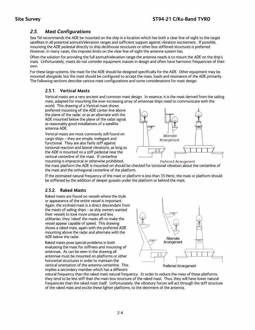
2.5.1. Vertical Masts Vertical masts are a very ancient and common mast design. In essence, it is the mast derived from the sailing mast, adapted for mounting the ever-increasing array of antennae ships need to communicate with the world. This drawing of a Vertical mast shows preferred mounting of the ADE center-line above the plane of the radar, or as an alternate with the ADE mounted below the plane of the radar signal, as reasonably good installations of a satellite antenna ADE.
Vertical masts are most commonly still found on cargo ships – they are simple, inelegant and functional. They are also fairly stiff against torsional reaction and lateral vibrations, as long as the ADE is mounted on a stiff pedestal near the vertical centerline of the mast. If centerline mounting is impractical or otherwise prohibited, the mast platform the ADE is mounted on should be checked for torsional vibration about the centerline of the mast and the orthogonal centerline of the platform.
If the estimated natural frequency of the mast or platform is less than 35 Hertz, the mast or platform should be stiffened by the addition of deeper gussets under the platform or behind the mast.
2.5.2. Raked Masts Raked masts are found on vessels where the style or appearance of the entire vessel is important. Again, the inclined mast is a direct descendant from the masts of sailing ships – as ship owners wanted their vessels to look more unique and less utilitarian, they ‘raked’ the masts aft to make the vessel appear capable of speed. This drawing shows a raked mast, again with the preferred ADE mounting above the radar and alternate with the ADE below the radar.
Raked masts pose special problems in both evaluating the mast for stiffness and mounting of antennae. As can be seen in the drawing all antennae must be mounted on platforms or other horizontal structures in order to maintain the vertical orientation of the antenna centerline. This implies a secondary member which has a different natural frequency than the raked mast natural frequency. In order to reduce the mass of these platforms, they tend to be less stiff than the main box structure of the raked mast. Thus, they will have lower natural frequencies than the raked mast itself. Unfortunately, the vibratory forces will act through the stiff structure of the raked mast and excite these lighter platforms, to the detriment of the antenna.

ST94-21 C/Ku-Band TVRO Site Survey
2-5
2.5.3. Girder Masts Girder masts are large platforms atop a pair of columns. Just like girder constructions in buildings, they are relatively stiff athwart ship – in their primary axis – but less stiff longitudinally and torsionally. An example of a girder mast is shown in this drawing, with the preferred ADE mounting outboard and above the radar directly on one of the columns and alternate with the ADE centered on the girder above the plane of the radar.
The greatest weakness of girder masts is in torsion – where the girder beam twists about its vertical centerline axis. As with all mast designs discussed so far, mounting the antenna in line with the vertical support structure will reduce the vibration tendencies. Mounting the antenna directly above the girder columns provides ample support to the antenna pedestal and locates the antenna weight where it will influence the natural frequency of the mast the least.
2.5.4. Truss Mast Truss masts are a variant on the girder mast concept. Rather than a pair of columns supporting a girder beam, the construction is a framework of tubular members supporting a platform on which the antennae and other equipment is mounted. A typical truss mast is shown in this photograph.
Like a girder mast, truss masts are especially stiff in the athwart ship direction. Unlike a girder mast, the truss can be made to be nearly as stiff in the longitudinal direction. Truss masts are particularly difficult to estimate the natural frequency – since a correct modeling includes both the truss structure of the supports and the plate/diaphragm structure of the platform. In general, though, the following guidelines apply when determining the adequate support for mounting an antenna on a truss mast:
1. Antenna ADE pedestal gussets should align with platform stiffeners which are at least 200 millimeters in depth and 10 millimeters in thickness.
2. When possible, the antenna ADE pedestal column should align with a vertical truss support.
3. For every 100 Kilograms of ADE weight over 250 Kilograms, the depth of the platform stiffeners should be increased by 50 millimeters and thickness by 2 millimeters.
Sea Tel does not have a recommended arrangement for a truss mast – the variability of truss mast designs means that each installation needs to be evaluated separately.
2.6. Safe Access to the ADE Safe access to the ADE should be provided. Provisions of the ship’s Safety Management System with regard to men aloft should be reviewed and agreed with all personnel prior to the installation. Installations greater than 3 meters above the deck (or where the access starts at a deck less than 1 meter in width) without cages around the access ladder shall be provided with means to latch a safety harness to a fixed horizontal bar or ring.
The access hatch for the ADE shall be oriented aft, or inboard, when practical. In any case, the orientation of the ADE access hatch shall comply with the SMS guidelines onboard the ship. Nets and other safety rigging under the ADE during servicing should be rigged to catch falling tools, components or fasteners.
2.7. Below Decks Equipment Location The Antenna Control Unit, Terminal Mounting Strip and Base Modem Panel are all standard 19” rack mount, therefore, preferred installation of these items would be in such a rack. The ACU mounts from the front of the rack. The Terminal Mounting Strip and Base Modem Panel mount on the rear of the rack.

Site Survey ST94-21 C/Ku-Band TVRO
2-6
The Satellite Modem, router, VIOP adapter(s), telephone equipment, fax machine, computers and any other associated equipment should also be properly mounted for shipboard use.
Plans to allow access to the rear of the ACU should be considered.
2.8. Cables During the site survey, walk the path that the cables will be installed along. Pay particular attention to how cables will be installed all along the path, what obstacles will have to have be routed around, difficulties that will be encountered and the overall length of the cables. The ADE should be installed using good electrical practice. Sea Tel recommends referring to IEC 60092-352 for specific guidance in choosing cables and installing cables onboard a ship. Within these guidelines, Sea Tel will provide some very general information regarding the electrical installation.
In general, all cable shall be protected from chaffing and secured to a cableway. Cable runs on open deck or down a mast shall be in metal conduit suitable for marine use. The conduit shall be blown through with dry air prior to passing cable to ensure all debris has been cleared out of the conduit and again after passing the cable to ensure no trapped moisture exists. The ends of the conduit shall be sealed with cable glands (preferred), mastic or low VOC silicon sealant after the cables have been passed through.
Cables passing through bulkheads or decks shall be routed through approved weather tight glands.
2.8.1. ADE/BDE Coaxial Cables The first concern about the coaxial cables installed between the ADE & BDE is length. This length is used to determine the loss of the various possible coax, Heliax or fiber-optic cables that might be used. You should always provide the lowest loss cables to provide the strongest signal level into the satellite modem.
Signal cable shall be continuous from the connection within the ADE radome, through the structure of the ship to the BDE. Splices, adapters or dummy connections will degrade the signal level and are discouraged.
Be careful of sharp bends that kink and damage the cable. Use a proper tubing bender for Heliax bends.
Penetrations in watertight bulkheads are very expensive, single cable, welded penetrations that must be pressure tested.
Always use good quality connectors that are designed to fit properly on the cables you are using. Poor quality connectors have higher loss, can allow noise into the cable , are easily damaged or fail prematurely.
In as much as is possible, don’t lay the coaxes on power cables. Try to have some separation from Inmarsat & GPS cables that are also passing L-band frequencies or Radar cables that may inject pulse repetition noise –as error bits - into your cables.
2.8.2. Antenna Power Cable Be cautious of length of the run, for voltage loss issues, and assure that the gauge of the wires is adequate for the current that is expected to be drawn (plus margin). Antenna power is not required to be from a UPS (same one that supplies power to the below decks equipment), but it is recommended.
Power cable shall comply with the provisions of IEC 60092-350 and -351 in so far as practicable. Power cable may be routed through the same conduit as the signal cable from the junction box to the base of the ADE. Power cables shall pass through separate radome penetrations from the signal cable.
The power cable shall be continuous from the UPS (or closest circuit breaker) to the ADE connections within the radome. The power circuits shall be arranged so that ‘active,’ ‘common’ and ‘neutral’ (ground) legs are all made or broken simultaneously. All circuit legs shall be carried in the same cable jacket.
2.8.3. Air Conditioner Power Cable If your system includes a marine air conditioner, run an AC power cable to it from a breaker, preferably from a different phase of the electrical system than that which supplies power to the ADE & BDE. Be EXTREMELY cautious of length of the run for voltage loss and gauge of the wires for the current that is expected to be drawn.
Power cable shall comply with the provisions of IEC 60092-350 and -351 in so far as practicable. Power cable may be routed through the same conduit as the signal cable from the junction box to the base of the ADE. Power cables shall pass through separate radome penetrations from the signal cable.
The power cable shall be continuous from the closest circuit breaker to the ADE connections within the radome. The power circuits shall be arranged so that ‘active,’ ‘common’ and ‘neutral’ (ground) legs are all made or broken simultaneously. All circuit legs shall be carried in the same cable jacket.
ST94-21 C/Ku-Band TVRO Site Survey
2-7
2.8.4. ACU Power Cable/Outlet The AC power for the ACU and other below decks equipment is not required to be from a UPS (same one that supplies power to the ADE), but it is recommended.
Power cable shall comply with the provisions of IEC 60092-350 and -351 in so far as practicable.
2.8.5. Gyro Compass Cable Use good quality shielded cable (twisted pairs, individually foil wrapped, outer foil with braid overall is best) You only need 2-wire for NMEA signal, 4-wire for Step-By-Step and 5-wire for Synchro … always use shielded cable. Be cautious of length and gauge of the run for voltage loss issues.
2.8.6. Grounding Refer to the Installation chapter for grounding/bonding information.

Site Survey ST94-21 C/Ku-Band TVRO
2-8
This Page Intentionally Left Blank

ST94-21 C/Ku-Band TVRO Installation
3-1
3. Installation This section contains instructions for unpacking, final assembly and installation of the equipment. It is highly recommended that final assembly and installation of the Antenna system be performed by trained technicians. Read this complete section before starting.
3.1. General Cautions & Warnings
WARNING: Assure that all nut & bolt assemblies are tightened according to the tightening torque values listed below:
SAE Bolt Size Inch Pounds Metric Bolt Size Kg-cm
1/4-20 75 M6 75.3
5/l6-18 132 M8 150
3/8-16 236 M10 270
1/2-13 517 M12 430
NOTE: All nuts and bolts should be assembled using the appropriate Loctite thread-locker product number for the thread size of the hardware.
Loctite # Description
222 Low strength for small fasteners.
242 Medium strength
638 High strength for Motor Shafts & Sprockets.
2760 Permanent strength for up to 1” diameter fasteners.
290 Wicking, High strength for fasteners which are already assembled.
WARNING: Hoisting with other than a webbed four-part sling may result in catastrophic crushing of the radome. Refer to the specifications and drawings for the fully assembled weight of your model Antenna/Radome and assure that equipment used to lift/hoist this system is rated accordingly.
CAUTION: The antenna/radome assembly is very light for its size and is subject to large swaying motions if hoisted under windy conditions. Always ensure that tag lines, attached to the radome base frame, are attended while the antenna assembly is being hoisted to its assigned location aboard ship.
WARNING: Electrical Hazard – Dangerous AC Voltages exist inside the Antenna Pedestal Breaker Box. Observe proper safety precautions when working inside the Pedestal Breaker Box.
WARNING: Electrical Hazard – Dangerous AC Voltages exists on the side of the Antenna Pedestal Power Supply. Observe proper safety precautions when working inside the Pedestal Power Supply.
Installation ST94-21 C/Ku-Band TVRO
3-2
3.2. Site Selection Aboard Ship The radome assembly should be installed at a location aboard ship where:
• The antenna has a clear line-of-sight to view as much of the sky (horizon to zenith at all bearings) as is practical.
• X-Band (3cm) Navigational Radars:
• The ADE should be mounted more than 0.6 meters/2 feet from 2kW (24 km) radars
• The ADE should be mounted more than 2 meters/8 feet from 10kW (72 km) radars
• The ADE should be mounted more than 4 meters/12 feet from 160kW (250km) radars
• S-Band (10cm) Navigational Radars:
• If the ADE is/has C-Band it should be mounted more than 4 meters/12 feet from the S-band Radar.
• The ADE should not be mounted on the same plane as the ship's Radar, so that it is not directly in the Radar beam path.
• The ADE should be mounted more than 2.5 meters/8 feet from any high power MF/HF antennas (<400W).
• The ADE should be mounted more than 4 meters/12 feet from any high power MF/HF antennas (1000W).
• The ADE should also be mounted more than 4 meters/12 feet from any short range (VHF/UHF) antennae.
• The ADE should be mounted more than 2.5 meters/8 feet away from any L-band satellite antenna.
• The ADE should be mounted more than 3 meters/10 feet away from any magnetic compass installations.
• The ADE should be mounted more than 2.5 meters/8 feet away from any GPS receiver antennae.
• Another consideration for any satellite antenna mounting is multi-path signals (reflection of the satellite signal off of nearby surfaces arriving out of phase with the direct signal from the satellite) to the antenna. This is particularly a problem for the onboard GPS, and/or the GPS based Satellite Compass.
• The Above Decks Equipment (ADE) and the Below Decks Equipment (BDE) should be positioned as close to one another as possible. This is necessary to reduce the losses associated with long cable runs.
• This mounting platform must also be robust enough to withstand the forces exerted by full rated wind load on the radome.
• The mounting location is robust enough that it will not flex or sway in ships motion and be sufficiently well re-enforced to prevent flex and vibration forces from being exerted on the antenna and radome.
• If the radome is to be mounted on a raised pedestal, it MUST have adequate size, wall thickness and gussets to prevent flexing or swaying in ships motion. In simple terms it must be robust.
If these conditions cannot be entirely satisfied, the site selection will inevitably be a “best” compromise between the various considerations.
3.3. Preparation It is recommended that you do not unpack the crates until you are ready to sub-assemble and install the equipment. Assure that you have a large, flat, level, open area to sub-assembly the baseframe, pedestal, dish/feed and the upper & lower sections of the radome. This area should be clean and free of debris (refer to the Installation chapters of Antenna and Antenna Control Unit manuals).
We recommend that you place the crates in the area that you have chosen to assembly each of these major components.
3.4. Opening your crates
CAUTION: To prevent items from being lost or misplaced, do not unpack this crate until you are ready to assemble and install the equipment.
ST94-21 C/Ku-Band TVRO Installation
3-3
3.4.1. Location of Items inside the Crates New packing lists for the crates make it easier to locate and unpack the items that are needed to assemble and install the Antenna System. Crate design make it easier to unpack the items from each crate. All bolts, mounting the equipment in the crate can be removed from the top side. There is no longer any need to reach under the pallet to hold nuts while the bolts are being removed!,
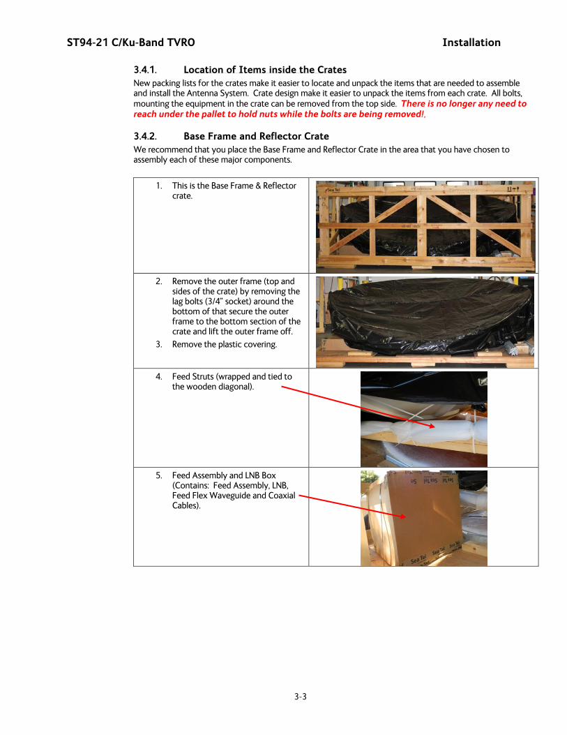
3.4.2. Base Frame and Reflector Crate We recommend that you place the Base Frame and Reflector Crate in the area that you have chosen to assembly each of these major components.
1. This is the Base Frame & Reflector crate.
2. Remove the outer frame (top and
sides of the crate) by removing the lag bolts (3/4” socket) around the bottom of that secure the outer frame to the bottom section of the crate and lift the outer frame off.
3. Remove the plastic covering.
4. Feed Struts (wrapped and tied to
the wooden diagonal).
5. Feed Assembly and LNB Box
(Contains: Feed Assembly, LNB, Feed Flex Waveguide and Coaxial Cables).
Installation ST94-21 C/Ku-Band TVRO
3-4
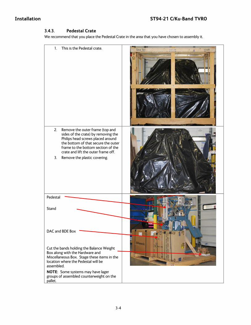
3.4.3. Pedestal Crate We recommend that you place the Pedestal Crate in the area that you have chosen to assembly it.
1. This is the Pedestal crate.
2. Remove the outer frame (top and
sides of the crate) by removing the Philips head screws placed around the bottom of that secure the outer frame to the bottom section of the crate and lift the outer frame off.
3. Remove the plastic covering.
Pedestal
Stand
DAC and BDE Box
Cut the bands holding the Balance Weight Box along with the Hardware and Miscellaneous Box. Stage these items in the location where the Pedestal will be assembled.
NOTE: Some systems may have lager groups of assembled counterweight on the pallet.

ST94-21 C/Ku-Band TVRO Installation
3-5
3.4.4. Radome Crate: We recommend that you place the Radome Crate in the area that you have chosen to assemble the Radome onto the base frame.
1. This is the Radome crate.
2. Remove the clips around the removable crate wall to expose the contents.
Radome Panels
Radome hardware kit
Silicon Adhesive
Radome Cap
3.5. Unpacking the Base Frame and Reflector Crate The Base Frame and Reflector now share the same crate. The Base Frame is on the lower deck under the Reflector support structure. The Base Frame, Legs, Feet, Supports and Hardware Kit are located on this crate. The Reflector, the Boxes containing the Feed & LNB Assembly (Assemblies if two), along with the Feed Struts and Hardware Kit are located in this crate. If there are two Feed & LNB units they will each be in separate boxes.
Unpacking the Base Fame and Reflector:
1. Open the crate, to expose the contents, as described above.

Installation ST94-21 C/Ku-Band TVRO
3-6
2. Remove the lower lag bolts from the “L” brackets (left and right) that hold the reflector support structure legs to the crate.
Note: There is one “L” bracket on each side. Only remove the lower lag bolt from the “L” brackets.
3. Lift the reflector support structure up about
2 feet.
CAUTION: Be careful not to lift the supports to more than the necessary height as this could cause the reflector to flip over.
4. Allow the drop down legs on the reflector
support to swing down to support the structure in the raised position.
ST94-21 C/Ku-Band TVRO Installation
3-7
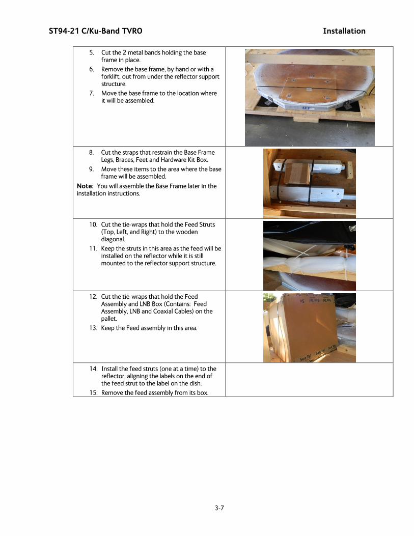
5. Cut the 2 metal bands holding the base frame in place.
6. Remove the base frame, by hand or with a forklift, out from under the reflector support structure.
7. Move the base frame to the location where it will be assembled.
8. Cut the straps that restrain the Base Frame
Legs, Braces, Feet and Hardware Kit Box.
9. Move these items to the area where the base frame will be assembled.
Note: You will assemble the Base Frame later in the installation instructions.
10. Cut the tie-wraps that hold the Feed Struts
(Top, Left, and Right) to the wooden diagonal.
11. Keep the struts in this area as the feed will be installed on the reflector while it is still mounted to the reflector support structure.
12. Cut the tie-wraps that hold the Feed
Assembly and LNB Box (Contains: Feed Assembly, LNB and Coaxial Cables) on the pallet.
13. Keep the Feed assembly in this area.
14. Install the feed struts (one at a time) to the
reflector, aligning the labels on the end of the feed strut to the label on the dish.
15. Remove the feed assembly from its box.
Installation ST94-21 C/Ku-Band TVRO
3-8
16. Mount the feed assembly with the Linear drive motor at the bottom strut.
Linear Drive Motor
Bottom Strut
17. Assemble the Feed Assembly to the feed
struts, aligning the labels on the end of the feed strut to the label on the feed assembly.
18. Keep the assembled reflector/feed assembly mounted on the reflector support structure until you are ready to install it on the Pedestal.
Note: You will install the reflector later in the installation instructions.
3.6. Unpacking the Pedestal Crate The Pedestal crate contains the Pedestal Assembly, Spider, DAC & BDE box, RF units, Wave Guide boxes, Hardware Kits and the Air Conditioning unit if one is with the shipment. If there are two RF units the Wave Guide and hardware for each is in separate boxes.
Unpacking the Pedestal Crate:
1. Open the crate, to expose the contents, as described above.
2. Cut the bands holding the Balance Weight Box along with the Hardware and Miscellaneous Box. Stage these items in the location where the Pedestal will be assembled.
3. Cut the band holding the Hardware to assemble Pedestal to Spider. Assure that this hardware stays with the mounting spider.
4. Cut the remaining restraints and remove the mounting spider. Stage it with the location where the base frame will be assembled.
5. Cut the bands holding the DAC and BDE Box (pictured in center). Stage this box where the Below Decks Equipment is temporarily located.
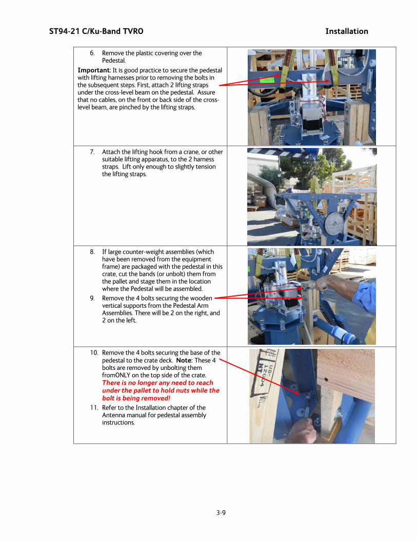
ST94-21 C/Ku-Band TVRO Installation
3-9
6. Remove the plastic covering over the Pedestal.
Important: It is good practice to secure the pedestal with lifting harnesses prior to removing the bolts in the subsequent steps. First, attach 2 lifting straps under the cross-level beam on the pedestal. Assure that no cables, on the front or back side of the cross-level beam, are pinched by the lifting straps.
7. Attach the lifting hook from a crane, or other
suitable lifting apparatus, to the 2 harness straps. Lift only enough to slightly tension the lifting straps.
8. If large counter-weight assemblies (which
have been removed from the equipment frame) are packaged with the pedestal in this crate, cut the bands (or unbolt) them from the pallet and stage them in the location where the Pedestal will be assembled.
9. Remove the 4 bolts securing the wooden vertical supports from the Pedestal Arm Assemblies. There will be 2 on the right, and 2 on the left.
10. Remove the 4 bolts securing the base of the pedestal to the crate deck. Note: These 4 bolts are removed by unbolting them fromONLY on the top side of the crate. There is no longer any need to reach under the pallet to hold nuts while the bolt is being removed!
11. Refer to the Installation chapter of the Antenna manual for pedestal assembly instructions.

Installation ST94-21 C/Ku-Band TVRO
3-10
12. After removing these 8 bolts the Pedestal Assembly is free to be removed from the crate.
13. Use a crane, or other suitable lifting apparatus, to lift the pedestal off of the crate and relocate it to the area where the pedestal will be sub-assembled.
3.7. Unpacking the Radome Crate: It is recommended that you do not unpack the crates until you are ready to sub-assemble the equipment. This crate should be place in the location that you have chosen to assemble the radome onto the base frame.
Unpacking the Radome Crate:
1. Open the crate, to expose the contents, as described above.
2. Use diagonal cutters, or shears, to cut the bands that restrain the radome panels in the crate. Do not remove the panels at this time, they will be removed during the radome assembly (refer to the Antenna Manual, Installation chapter).
3. Remove the straps that restrain the radome
cap. Leave the radome cap on the pallet with the radome panels for use during the radome assembly.
4. Use diagonal cutters, or shears, to cut the bands that restrain the Hardware kit in the crate. Leave the hardware kit on the pallet with the radome panels for use during the radome assembly.
5. Use diagonal cutters, or shears, to cut the bands that restrain the box of Silicon Adhesive in the crate. Leave the Silicon Adhesive on the pallet with the radome panels for use during the radome assembly.
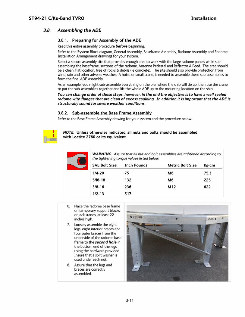
ST94-21 C/Ku-Band TVRO Installation
3-11
3.8. Assembling the ADE
3.8.1. Preparing for Assembly of the ADE Read this entire assembly procedure before beginning.
Refer to the System Block diagram, General Assembly, Baseframe Assembly, Radome Assembly and Radome Installation Arrangement drawings for your system.
Select a secure assembly site that provides enough area to work with the large radome panels while sub-assembling the baseframe, sections of the radome, Antenna Pedestal and Reflector & Feed. The area should be a clean, flat location, free of rocks & debris (ie concrete). The site should also provide protection from wind, rain and other adverse weather. A hoist, or small crane, is needed to assemble these sub-assemblies to form the final ADE Assembly.
As an example, you might sub-assemble everything on the pier where the ship will tie up, then use the crane to put the sub-assemblies together and lift the whole ADE up to the mounting location on the ship.
You can change order of these steps, however, in the end the objective is to have a well sealed radome with flanges that are clean of excess caulking. In addition it is important that the ADE is structurally sound for severe weather conditions.
3.8.2. Sub-assemble the Base Frame Assembly Refer to the Base Frame Assembly drawing for your system and the procedure below.
NOTE: Unless otherwise indicated, all nuts and bolts should be assembled with Loctite 2760 or its equivalent.
WARNING: Assure that all nut and bolt assemblies are tightened according to the tightening torque values listed below:
SAE Bolt Size Inch Pounds Metric Bolt Size Kg-cm
1/4-20 75 M6 75.3
5/l6-18 132 M6 225
3/8-16 236 M12 622
1/2-13 517
6. Place the radome base frame on temporary support blocks, or jack stands, at least 22 inches high.
7. Loosely assemble the eight legs, eight interior braces and four outer braces from the underside of the radome base frame to the second hole in the bottom end of the legs using the hardware provided. Insure that a split washer is used under each nut.
8. Assure that the legs and braces are correctly assembled.
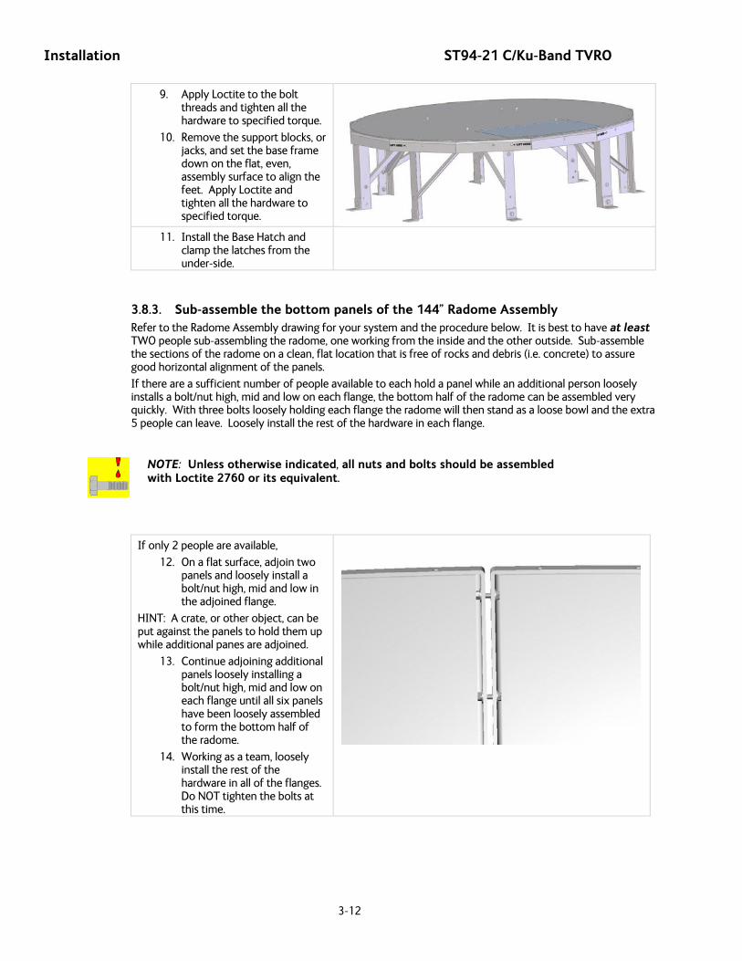
Installation ST94-21 C/Ku-Band TVRO
3-12
9. Apply Loctite to the bolt threads and tighten all the hardware to specified torque.
10. Remove the support blocks, or jacks, and set the base frame down on the flat, even, assembly surface to align the feet. Apply Loctite and tighten all the hardware to specified torque.
11. Install the Base Hatch and clamp the latches from the under-side.
3.8.3. Sub-assemble the bottom panels of the 144” Radome Assembly Refer to the Radome Assembly drawing for your system and the procedure below. It is best to have at least TWO people sub-assembling the radome, one working from the inside and the other outside. Sub-assemble the sections of the radome on a clean, flat location that is free of rocks and debris (i.e. concrete) to assure good horizontal alignment of the panels.
If there are a sufficient number of people available to each hold a panel while an additional person loosely installs a bolt/nut high, mid and low on each flange, the bottom half of the radome can be assembled very quickly. With three bolts loosely holding each flange the radome will then stand as a loose bowl and the extra 5 people can leave. Loosely install the rest of the hardware in each flange.
NOTE: Unless otherwise indicated, all nuts and bolts should be assembled with Loctite 2760 or its equivalent.
If only 2 people are available,
12. On a flat surface, adjoin two panels and loosely install a bolt/nut high, mid and low in the adjoined flange.
HINT: A crate, or other object, can be put against the panels to hold them up while additional panes are adjoined.
13. Continue adjoining additional panels loosely installing a bolt/nut high, mid and low on each flange until all six panels have been loosely assembled to form the bottom half of the radome.
14. Working as a team, loosely install the rest of the hardware in all of the flanges. Do NOT tighten the bolts at this time.
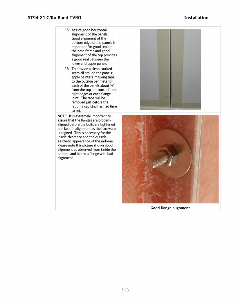
ST94-21 C/Ku-Band TVRO Installation
3-13
15. Assure good horizontal alignment of the panels. Good alignment of the bottom edge of the panels is important for good seal on the base frame and good alignment of the top provides a good seal between the lower and upper panels.
16. To provide a clean caulked seam all around the panels: apply painters’ masking tape to the outside perimeter of each of the panels about ¼” from the top, bottom, left and right edges at each flange joint. The tape will be removed just before the radome caulking has had time to set.
NOTE: It is extremely important to assure that the flanges are properly aligned before the bolts are tightened and kept in alignment as the hardware is aligned. This is necessary for the inside clearance and the outside aesthetic appearance of the radome. Please note this picture shown good alignment as observed from inside the radome and below a flange with bad alignment.
Good flange alignment
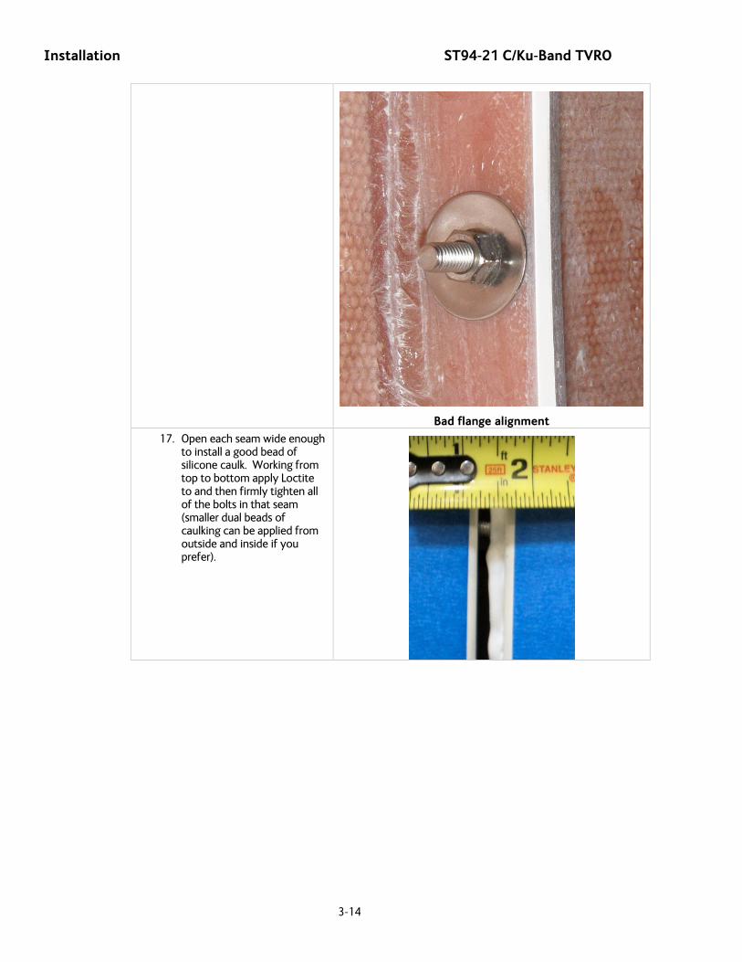
Installation ST94-21 C/Ku-Band TVRO
3-14
Bad flange alignment
17. Open each seam wide enough to install a good bead of silicone caulk. Working from top to bottom apply Loctite to and then firmly tighten all of the bolts in that seam (smaller dual beads of caulking can be applied from outside and inside if you prefer).
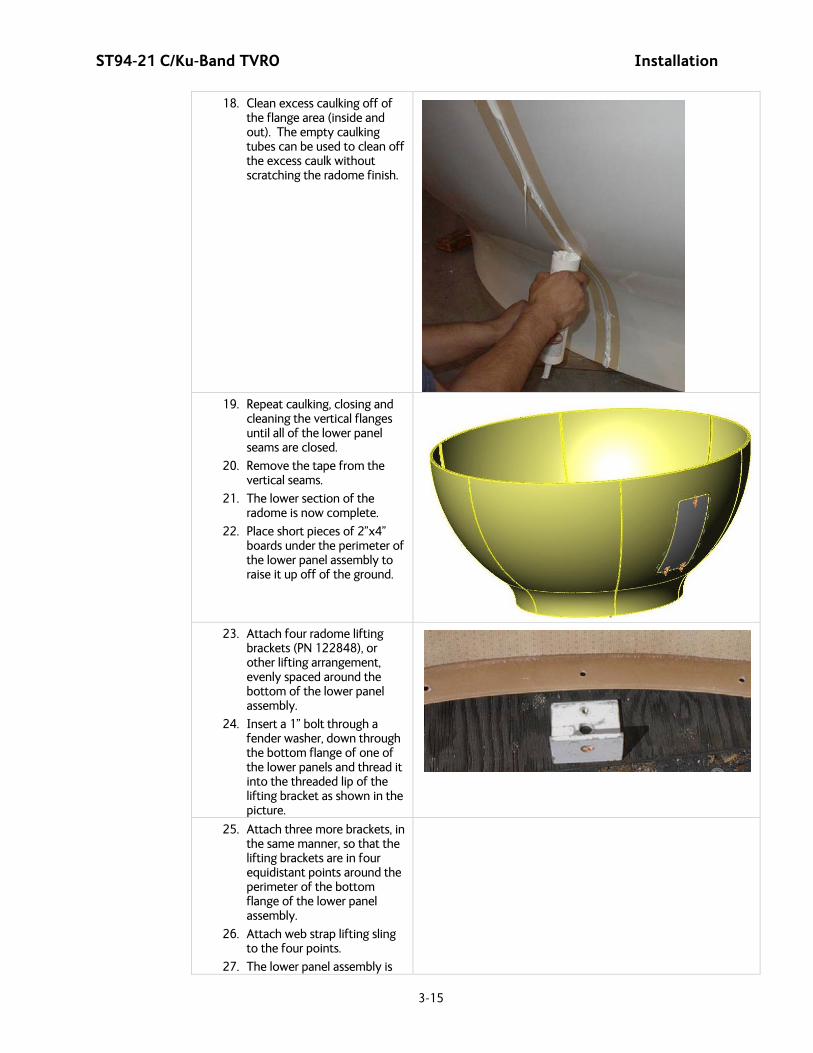
ST94-21 C/Ku-Band TVRO Installation
3-15
18. Clean excess caulking off of the flange area (inside and out). The empty caulking tubes can be used to clean off the excess caulk without scratching the radome finish.
19. Repeat caulking, closing and
cleaning the vertical flanges until all of the lower panel seams are closed.
20. Remove the tape from the vertical seams.
21. The lower section of the radome is now complete.
22. Place short pieces of 2”x4” boards under the perimeter of the lower panel assembly to raise it up off of the ground.
23. Attach four radome lifting
brackets (PN 122848), or other lifting arrangement, evenly spaced around the bottom of the lower panel assembly.
24. Insert a 1” bolt through a fender washer, down through the bottom flange of one of the lower panels and thread it into the threaded lip of the lifting bracket as shown in the picture.
25. Attach three more brackets, in the same manner, so that the lifting brackets are in four equidistant points around the perimeter of the bottom flange of the lower panel assembly.
26. Attach web strap lifting sling to the four points.
27. The lower panel assembly is
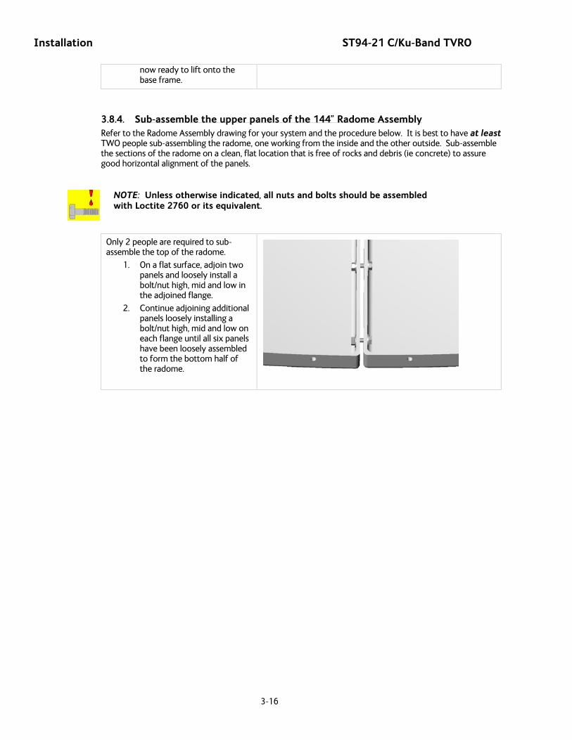
Installation ST94-21 C/Ku-Band TVRO
3-16
now ready to lift onto the base frame.
3.8.4. Sub-assemble the upper panels of the 144” Radome Assembly Refer to the Radome Assembly drawing for your system and the procedure below. It is best to have at least TWO people sub-assembling the radome, one working from the inside and the other outside. Sub-assemble the sections of the radome on a clean, flat location that is free of rocks and debris (ie concrete) to assure good horizontal alignment of the panels.
NOTE: Unless otherwise indicated, all nuts and bolts should be assembled with Loctite 2760 or its equivalent.
Only 2 people are required to sub-assemble the top of the radome.
1. On a flat surface, adjoin two panels and loosely install a bolt/nut high, mid and low in the adjoined flange.
2. Continue adjoining additional panels loosely installing a bolt/nut high, mid and low on each flange until all six panels have been loosely assembled to form the bottom half of the radome.
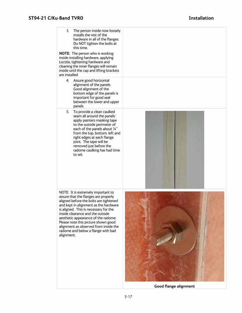
ST94-21 C/Ku-Band TVRO Installation
3-17
3. The person inside now loosely installs the rest of the hardware in all of the flanges. Do NOT tighten the bolts at this time.
NOTE: The person who is working inside installing hardware, applying Loctite, tightening hardware and cleaning the inner flanges will remain inside until the cap and lifting brackets are installed.
4. Assure good horizontal alignment of the panels. Good alignment of the bottom edge of the panels is important for good seal between the lower and upper panels.
5. To provide a clean caulked seam all around the panels: apply painters masking tape to the outside perimeter of each of the panels about ¼“ from the top, bottom, left and right edges at each flange joint. The tape will be removed just before the radome caulking has had time to set.
NOTE: It is extremely important to assure that the flanges are properly aligned before the bolts are tightened and kept in alignment as the hardware is aligned. This is necessary for the inside clearance and the outside aesthetic appearance of the radome. Please note this picture shown good alignment as observed from inside the radome and below a flange with bad alignment.
Good flange alignment

Installation ST94-21 C/Ku-Band TVRO
3-18
Bad flange alignment
6. Open each seam wide enough to install a good bead of silicone caulk. Working from top to bottom apply Loctite to and then firmly tighten all of the bolts in that seam (smaller dual beads of caulking can be applied from outside and inside if you prefer).
7. Clean excess caulking off of
the flange areas inside and outside the radome.
8. Repeat caulking, closing and cleaning the vertical flanges until all of the upper panel seams are closed.
9. Remove tape from the vertical seams.

ST94-21 C/Ku-Band TVRO Installation
3-19
10. Apply a 3/8” layer of caulking to the under-side of the perimeter flange of radome cap.
11. (Outside person) Climb onto
the upper panel assembly, have someone (third person required only for this step) hand the cap to the person on top of the radome.
12. Insert the cap into the top of the radome with a twisting rotation. This will evenly spread the caulking and align the bolt holes inside the radome top (coordinate with the person inside the radome).
13. (Inside Person) Install the
radome cap using the provided hardware. CAUTION: Do NOT over tighten the hardware. Only tighten until the fiberglass STARTS to flex.
14. Apply additional caulking to fill gaps between the upper panels and the cap.
15. Clean off excess caulking.
16. The upper section of the radome is now complete.
17. Place short pieces of 2”x4” boards under the perimeter of the radome top to raise it up off of the ground.
18. Attach radome lifting brackets (PN 122848), or other lifting arrangement, around the bottom of the upper panel assembly.
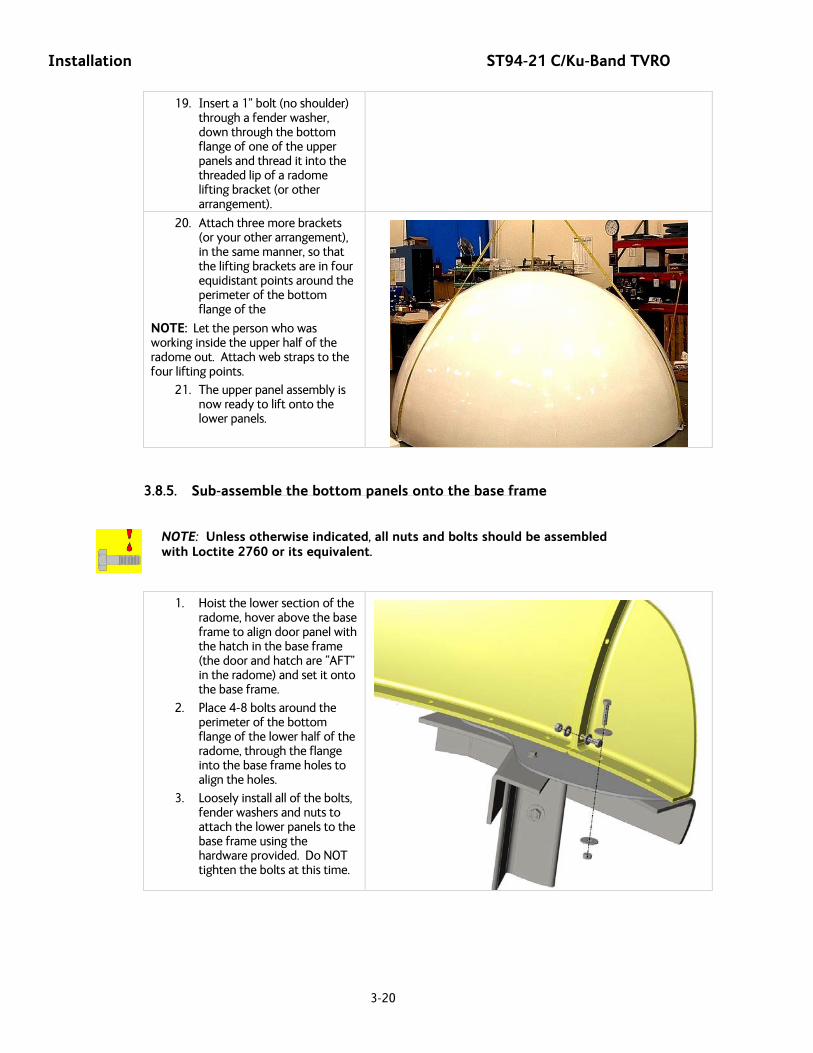
Installation ST94-21 C/Ku-Band TVRO
3-20
19. Insert a 1” bolt (no shoulder) through a fender washer, down through the bottom flange of one of the upper panels and thread it into the threaded lip of a radome lifting bracket (or other arrangement).
20. Attach three more brackets (or your other arrangement), in the same manner, so that the lifting brackets are in four equidistant points around the perimeter of the bottom flange of the
NOTE: Let the person who was working inside the upper half of the radome out. Attach web straps to the four lifting points.
21. The upper panel assembly is now ready to lift onto the lower panels.
3.8.5. Sub-assemble the bottom panels onto the base frame
NOTE: Unless otherwise indicated, all nuts and bolts should be assembled with Loctite 2760 or its equivalent.
1. Hoist the lower section of the radome, hover above the base frame to align door panel with the hatch in the base frame (the door and hatch are “AFT” in the radome) and set it onto the base frame.
2. Place 4-8 bolts around the perimeter of the bottom flange of the lower half of the radome, through the flange into the base frame holes to align the holes.
3. Loosely install all of the bolts, fender washers and nuts to attach the lower panels to the base frame using the hardware provided. Do NOT tighten the bolts at this time.

ST94-21 C/Ku-Band TVRO Installation
3-21
4. Use wedges to lift the lower panel assembly up off of the riser panels about ½ inch.
5. Install a good bead of caulking between the bottom of the lower panels and the base frame (smaller dual beads of caulking can be applied from outside and inside if you prefer) , remove the wedges, apply Loctite to and then firmly tighten all of the horizontal seam bolts.
6. Clean excess caulking off inside and outside of the radome.
7. Remove tape from the horizontal edges of the lower panels.
The bottom half of the radome is complete. Next you will assemble your antenna pedestal General Assembly and install it into this portion of the radome, before putting the top half of the radome on.
3.8.6. Sub-assemble the Antenna Pedestal Refer to the General Assembly drawing for your system and the procedure below.
1. Install the Base Stand onto the Base Pan using the hardware provided. Apply Loctite to and tighten the mounting bolts.
Note: As an alternative, the stand can be mounted to, and lifted with, the pedestal in step 12 below.
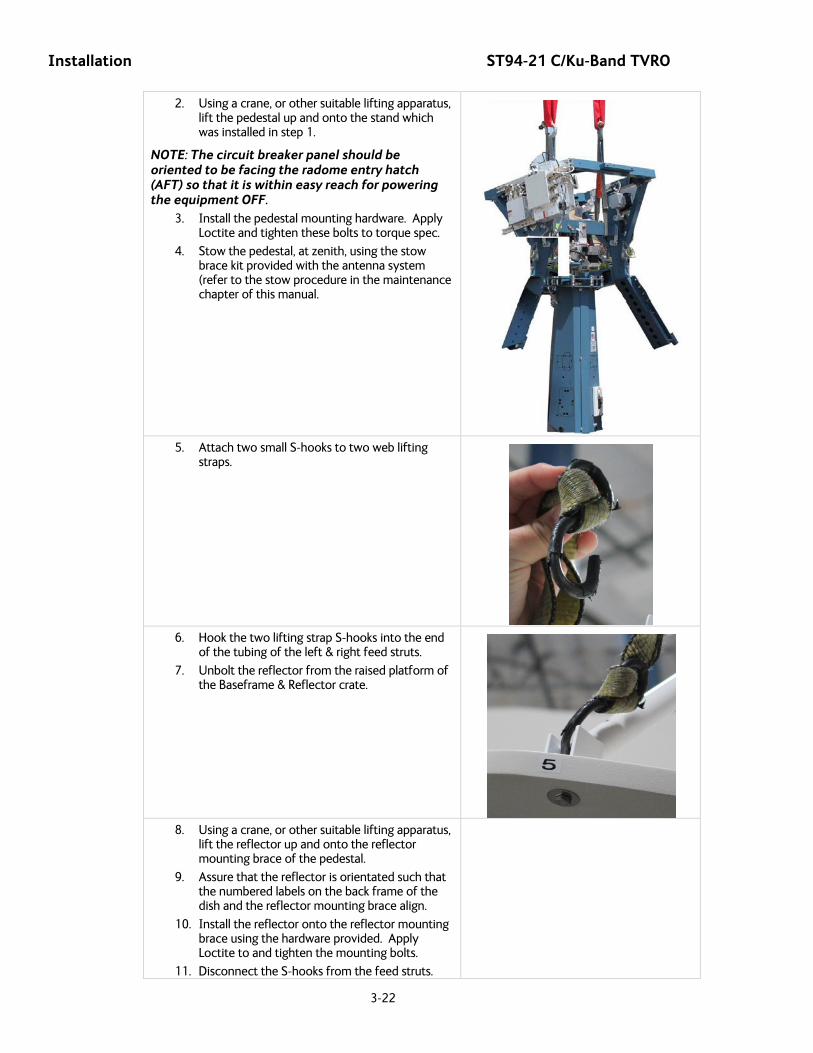
Installation ST94-21 C/Ku-Band TVRO
3-22
2. Using a crane, or other suitable lifting apparatus, lift the pedestal up and onto the stand which was installed in step 1.
NOTE: The circuit breaker panel should be oriented to be facing the radome entry hatch (AFT) so that it is within easy reach for powering the equipment OFF.
3. Install the pedestal mounting hardware. Apply Loctite and tighten these bolts to torque spec.
4. Stow the pedestal, at zenith, using the stow brace kit provided with the antenna system (refer to the stow procedure in the maintenance chapter of this manual.
5. Attach two small S-hooks to two web lifting
straps.
6. Hook the two lifting strap S-hooks into the end
of the tubing of the left & right feed struts.
7. Unbolt the reflector from the raised platform of the Baseframe & Reflector crate.
8. Using a crane, or other suitable lifting apparatus,
lift the reflector up and onto the reflector mounting brace of the pedestal.
9. Assure that the reflector is orientated such that the numbered labels on the back frame of the dish and the reflector mounting brace align.
10. Install the reflector onto the reflector mounting brace using the hardware provided. Apply Loctite to and tighten the mounting bolts.
11. Disconnect the S-hooks from the feed struts.
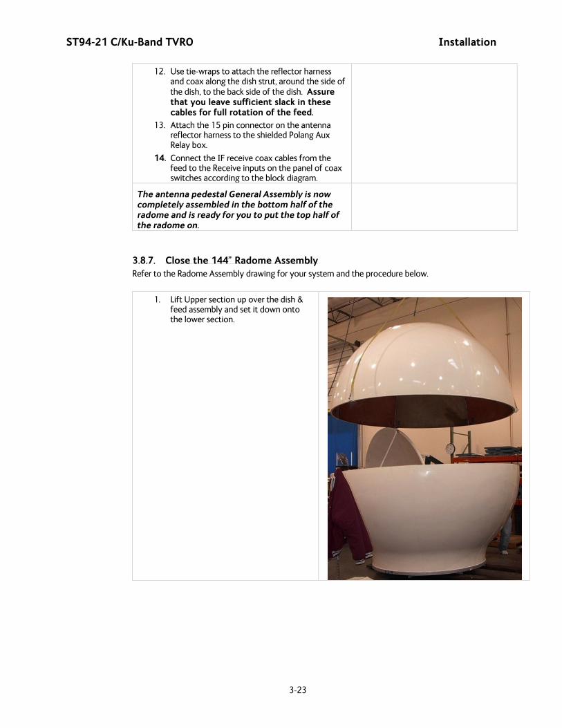
ST94-21 C/Ku-Band TVRO Installation
3-23
12. Use tie-wraps to attach the reflector harness and coax along the dish strut, around the side of the dish, to the back side of the dish. Assure that you leave sufficient slack in these cables for full rotation of the feed.
13. Attach the 15 pin connector on the antenna reflector harness to the shielded Polang Aux Relay box.
14. Connect the IF receive coax cables from the feed to the Receive inputs on the panel of coax switches according to the block diagram.
The antenna pedestal General Assembly is now completely assembled in the bottom half of the radome and is ready for you to put the top half of the radome on.
3.8.7. Close the 144” Radome Assembly Refer to the Radome Assembly drawing for your system and the procedure below.
1. Lift Upper section up over the dish & feed assembly and set it down onto the lower section.
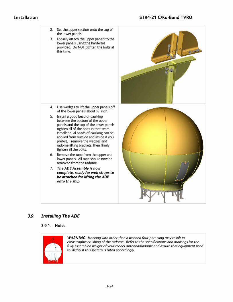
Installation ST94-21 C/Ku-Band TVRO
3-24
2. Set the upper section onto the top of the lower panels.
3. Loosely attach the upper panels to the lower panels using the hardware provided. Do NOT tighten the bolts at this time.
4. Use wedges to lift the upper panels off
of the lower panels about ½ inch.
5. Install a good bead of caulking between the bottom of the upper panels and the top of the lower panels tighten all of the bolts in that seam (smaller dual beads of caulking can be applied from outside and inside if you prefer). , remove the wedges and radome lifting brackets, then firmly tighten all the bolts.
6. Remove the tape from the upper and lower panels. All tape should now be removed from the radome.
7. The ADE Assembly is now complete, ready for web straps to be attached for lifting the ADE onto the ship.
3.9. Installing The ADE
3.9.1. Hoist
WARNING: Hoisting with other than a webbed four-part sling may result in catastrophic crushing of the radome. Refer to the specifications and drawings for the fully assembled weight of your model Antenna/Radome and assure that equipment used to lift/hoist this system is rated accordingly.
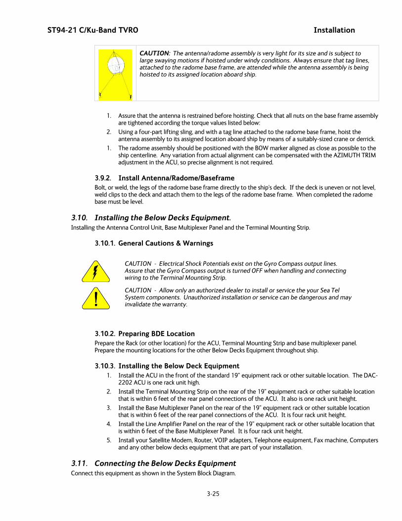
ST94-21 C/Ku-Band TVRO Installation
3-25
CAUTION: The antenna/radome assembly is very light for its size and is subject to large swaying motions if hoisted under windy conditions. Always ensure that tag lines, attached to the radome base frame, are attended while the antenna assembly is being hoisted to its assigned location aboard ship.
1. Assure that the antenna is restrained before hoisting. Check that all nuts on the base frame assembly are tightened according the torque values listed below:
2. Using a four-part lifting sling, and with a tag line attached to the radome base frame, hoist the antenna assembly to its assigned location aboard ship by means of a suitably-sized crane or derrick.
1. The radome assembly should be positioned with the BOW marker aligned as close as possible to the ship centerline. Any variation from actual alignment can be compensated with the AZIMUTH TRIM adjustment in the ACU, so precise alignment is not required.
3.9.2. Install Antenna/Radome/Baseframe Bolt, or weld, the legs of the radome base frame directly to the ship's deck. If the deck is uneven or not level, weld clips to the deck and attach them to the legs of the radome base frame. When completed the radome base must be level.
3.10. Installing the Below Decks Equipment. Installing the Antenna Control Unit, Base Multiplexer Panel and the Terminal Mounting Strip.
3.10.1. General Cautions & Warnings
CAUTION - Electrical Shock Potentials exist on the Gyro Compass output lines. Assure that the Gyro Compass output is turned OFF when handling and connecting wiring to the Terminal Mounting Strip.
CAUTION - Allow only an authorized dealer to install or service the your Sea Tel System components. Unauthorized installation or service can be dangerous and may invalidate the warranty.
3.10.2. Preparing BDE Location Prepare the Rack (or other location) for the ACU, Terminal Mounting Strip and base multiplexer panel. Prepare the mounting locations for the other Below Decks Equipment throughout ship.
3.10.3. Installing the Below Deck Equipment 1. Install the ACU in the front of the standard 19” equipment rack or other suitable location. The DAC-
2202 ACU is one rack unit high.
2. Install the Terminal Mounting Strip on the rear of the 19” equipment rack or other suitable location that is within 6 feet of the rear panel connections of the ACU. It also is one rack unit height.
3. Install the Base Multiplexer Panel on the rear of the 19” equipment rack or other suitable location that is within 6 feet of the rear panel connections of the ACU. It is four rack unit height.
4. Install the Line Amplifier Panel on the rear of the 19” equipment rack or other suitable location that is within 6 feet of the Base Multiplexer Panel. It is four rack unit height.
5. Install your Satellite Modem, Router, VOIP adapters, Telephone equipment, Fax machine, Computers and any other below decks equipment that are part of your installation.
3.11. Connecting the Below Decks Equipment Connect this equipment as shown in the System Block Diagram.
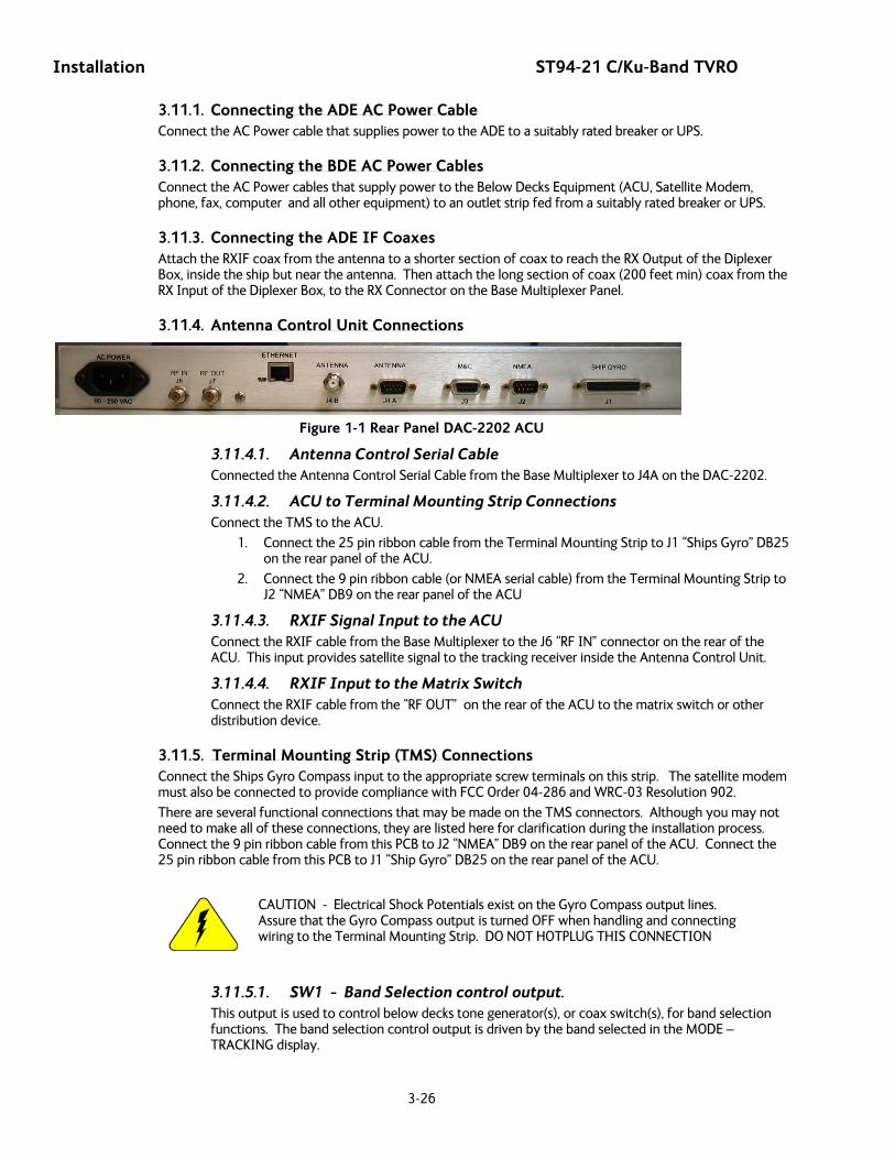
Installation ST94-21 C/Ku-Band TVRO
3-26
3.11.1. Connecting the ADE AC Power Cable Connect the AC Power cable that supplies power to the ADE to a suitably rated breaker or UPS.
3.11.2. Connecting the BDE AC Power Cables Connect the AC Power cables that supply power to the Below Decks Equipment (ACU, Satellite Modem, phone, fax, computer and all other equipment) to an outlet strip fed from a suitably rated breaker or UPS.
3.11.3. Connecting the ADE IF Coaxes Attach the RXIF coax from the antenna to a shorter section of coax to reach the RX Output of the Diplexer Box, inside the ship but near the antenna. Then attach the long section of coax (200 feet min) coax from the RX Input of the Diplexer Box, to the RX Connector on the Base Multiplexer Panel.
3.11.4. Antenna Control Unit Connections
Figure 1-1 Rear Panel DAC-2202 ACU
3.11.4.1. Antenna Control Serial Cable Connected the Antenna Control Serial Cable from the Base Multiplexer to J4A on the DAC-2202.
3.11.4.2. ACU to Terminal Mounting Strip Connections Connect the TMS to the ACU.
1. Connect the 25 pin ribbon cable from the Terminal Mounting Strip to J1 “Ships Gyro” DB25 on the rear panel of the ACU.
2. Connect the 9 pin ribbon cable (or NMEA serial cable) from the Terminal Mounting Strip to J2 “NMEA” DB9 on the rear panel of the ACU
3.11.4.3. RXIF Signal Input to the ACU Connect the RXIF cable from the Base Multiplexer to the J6 “RF IN” connector on the rear of the ACU. This input provides satellite signal to the tracking receiver inside the Antenna Control Unit.
3.11.4.4. RXIF Input to the Matrix Switch Connect the RXIF cable from the “RF OUT” on the rear of the ACU to the matrix switch or other distribution device.
3.11.5. 13Terminal Mounting Strip (TMS) Connections Connect the Ships Gyro Compass input to the appropriate screw terminals on this strip. The satellite modem must also be connected to provide compliance with FCC Order 04-286 and WRC-03 Resolution 902.
There are several functional connections that may be made on the TMS connectors. Although you may not need to make all of these connections, they are listed here for clarification during the installation process. Connect the 9 pin ribbon cable from this PCB to J2 “NMEA” DB9 on the rear panel of the ACU. Connect the 25 pin ribbon cable from this PCB to J1 “Ship Gyro” DB25 on the rear panel of the ACU.
CAUTION - Electrical Shock Potentials exist on the Gyro Compass output lines. Assure that the Gyro Compass output is turned OFF when handling and connecting wiring to the Terminal Mounting Strip. DO NOT HOTPLUG THIS CONNECTION
3.11.5.1. SW1 - Band Selection control output. This output is used to control below decks tone generator(s), or coax switch(s), for band selection functions. The band selection control output is driven by the band selected in the MODE – TRACKING display.
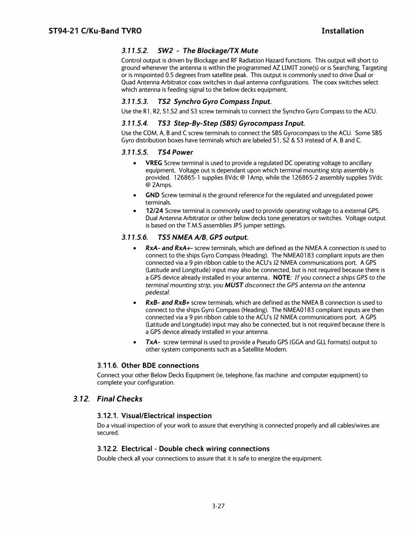
ST94-21 C/Ku-Band TVRO Installation
3-27
3.11.5.2. SW2 - The Blockage/TX Mute Control output is driven by Blockage and RF Radiation Hazard functions. This output will short to ground whenever the antenna is within the programmed AZ LIMIT zone(s) or is Searching, Targeting or is mispointed 0.5 degrees from satellite peak. This output is commonly used to drive Dual or Quad Antenna Arbitrator coax switches in dual antenna configurations. The coax switches select which antenna is feeding signal to the below decks equipment.
3.11.5.3. TS2 Synchro Gyro Compass Input. Use the R1, R2, S1,S2 and S3 screw terminals to connect the Synchro Gyro Compass to the ACU.
3.11.5.4. TS3 Step-By-Step (SBS) Gyrocompass Input. Use the COM, A, B and C screw terminals to connect the SBS Gyrocompass to the ACU. Some SBS Gyro distribution boxes have terminals which are labeled S1, S2 & S3 instead of A, B and C.
3.11.5.5. TS4 Power • VREG Screw terminal is used to provide a regulated DC operating voltage to ancillary
equipment. Voltage out is dependant upon which terminal mounting strip assembly is provided. 126865-1 supplies 8Vdc @ 1Amp, while the 126865-2 assembly supplies 5Vdc @ 2Amps.
• GND Screw terminal is the ground reference for the regulated and unregulated power terminals.
• 12/24 Screw terminal is commonly used to provide operating voltage to a external GPS, Dual Antenna Arbitrator or other below decks tone generators or switches. Voltage output is based on the T.M.S assemblies JP5 jumper settings.
3.11.5.6. TS5 NMEA A/B, GPS output.
• RxA- and RxA+- screw terminals, which are defined as the NMEA A connection is used to connect to the ships Gyro Compass (Heading). The NMEA0183 compliant inputs are then connected via a 9 pin ribbon cable to the ACU’s J2 NMEA communications port. A GPS (Latitude and Longitude) input may also be connected, but is not required because there is a GPS device already installed in your antenna.. NOTE: If you connect a ships GPS to the terminal mounting strip, you MUST disconnect the GPS antenna on the antenna pedestal.
• RxB- and RxB+ screw terminals, which are defined as the NMEA B connection is used to connect to the ships Gyro Compass (Heading). The NMEA0183 compliant inputs are then connected via a 9 pin ribbon cable to the ACU’s J2 NMEA communications port. A GPS (Latitude and Longitude) input may also be connected, but is not required because there is a GPS device already installed in your antenna.
• TxA- screw terminal is used to provide a Pseudo GPS (GGA and GLL formats) output to other system components such as a Satellite Modem.
3.11.6. Other BDE connections Connect your other Below Decks Equipment (ie, telephone, fax machine and computer equipment) to complete your configuration.
3.12. Final Checks
3.12.1. Visual/Electrical inspection Do a visual inspection of your work to assure that everything is connected properly and all cables/wires are secured.
3.12.2. Electrical - Double check wiring connections Double check all your connections to assure that it is safe to energize the equipment.

Installation ST94-21 C/Ku-Band TVRO
3-28
3.13. Power-Up Verify that all shipping straps and restrains have been removed prior to energizing the antenna. When all equipment has been installed, turn ACU Power and Antenna power ON. The ACU will initially sequentially display:
“SEA TEL – MASTER and DAC-2202 VER 6.xx” followed by,
“SEA TEL – RCVR and SCPC VER 5.xx” followed by,
“SEA TEL – IO MOD and COMMIF VER 1.xx” followed by,
“SEA TEL – REMOTE and INITIALIZING”. After initialization, the bottom line of the remote display will display the antenna model number and the software version from the PCU.
Energize and check the other Below Decks Equipment to verify that all the equipment is operating. You will need to assure that the ACU is setup correctly and that the antenna acquires the correct satellite before you will be able to completely check all the below decks equipment for proper operation.
3.14. Cable Terminations
3.14.1. At The Radome The TX and RX, or TVRO IF, cables must be inserted through the cable strain reliefs at the base of the radome. Apply RTV to the strain relief joints and tighten the compression fittings to make them watertight. Attach the pedestal cable adapters to the TX and RX, or TVRO IF, cables from below decks. Refer to the System Block Diagram.
AC Power cable for the Antenna Pedestal and RF Equipment is routed into the AC Power Breaker box and connected to the breaker terminals.
Sea Tel recommends that separate, dedicated, AC Power be provided for the Marine Air Conditioner (Do NOT combine with the AC Power provided for the Antenna Pedestal and RF Equipment). This AC Power cable is routed into the Marine Air Conditioner and terminated to the AC terminals inside.
3.14.2. ACU & TMS To Connect AC Power, Gyro Compass Connection and IF Input refer to the Antenna Control Unit manual. Installation of optional (remote) Pedestal, and /or Radio, Monitor & Control connection(s) from a PC Computer are also contained in the ACU manual.
3.14.3. Other BDE Equipment Refer to the vendor supplied manuals for installation of the other below decks equipment.
3.15. Final Assembly
3.15.1. Remove Stow Braces/Restraints Remove the restraints from the antenna and verify that the antenna moves freely in azimuth, elevation, and cross level without hitting any flanges on the radome.
3.15.2. Verify all assembly and Wiring connections Verify that all pedestal wiring and cabling is properly dressed and clamped in place.
3.16. Power-Up The ADE Turn Pedestal AC power breaker ON.
3.16.1. Initialization Turn the pedestal power supply ON. The PCU will initialize the stabilized portion of the mass to be level with the horizon and at a prescribed Azimuth and Elevation angles. The antenna will go through the specific sequence of steps to initialize the level cage, elevation, cross-level and azimuth to predetermined starting positions. Each phase must complete properly for the antenna to operate properly (post-initialization). Refer to the initialization text in the Troubleshooting section in this manual. Observe the Initialization of the antenna pedestal.
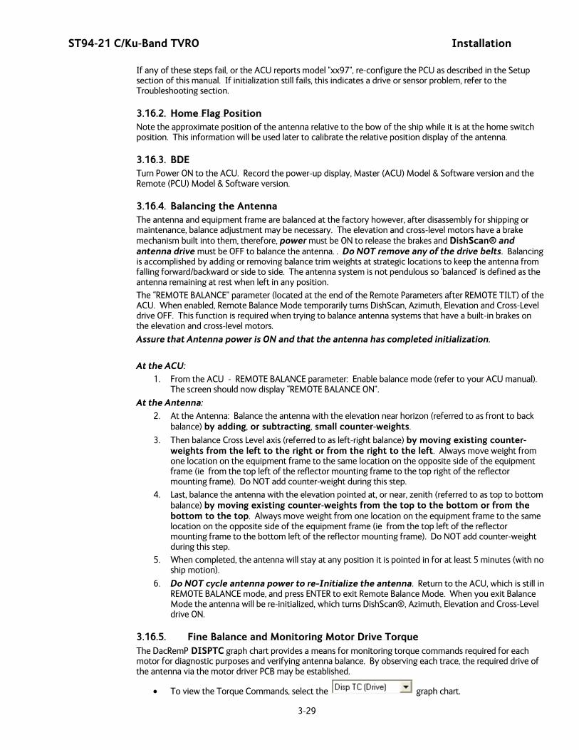
ST94-21 C/Ku-Band TVRO Installation
3-29
If any of these steps fail, or the ACU reports model "xx97", re-configure the PCU as described in the Setup section of this manual. If initialization still fails, this indicates a drive or sensor problem, refer to the Troubleshooting section.
3.16.2. Home Flag Position Note the approximate position of the antenna relative to the bow of the ship while it is at the home switch position. This information will be used later to calibrate the relative position display of the antenna.
3.16.3. BDE Turn Power ON to the ACU. Record the power-up display, Master (ACU) Model & Software version and the Remote (PCU) Model & Software version.
3.16.4. Balancing the Antenna The antenna and equipment frame are balanced at the factory however, after disassembly for shipping or maintenance, balance adjustment may be necessary. The elevation and cross-level motors have a brake mechanism built into them, therefore, power must be ON to release the brakes and DishScan® and antenna drive must be OFF to balance the antenna. . Do NOT remove any of the drive belts. Balancing is accomplished by adding or removing balance trim weights at strategic locations to keep the antenna from falling forward/backward or side to side. The antenna system is not pendulous so 'balanced' is defined as the antenna remaining at rest when left in any position.
The “REMOTE BALANCE” parameter (located at the end of the Remote Parameters after REMOTE TILT) of the ACU. When enabled, Remote Balance Mode temporarily turns DishScan, Azimuth, Elevation and Cross-Level drive OFF. This function is required when trying to balance antenna systems that have a built-in brakes on the elevation and cross-level motors.
Assure that Antenna power is ON and that the antenna has completed initialization.
At the ACU: 1. From the ACU - REMOTE BALANCE parameter: Enable balance mode (refer to your ACU manual).
The screen should now display “REMOTE BALANCE ON”.
At the Antenna: 2. At the Antenna: Balance the antenna with the elevation near horizon (referred to as front to back
balance) by adding, or subtracting, small counter-weights.
3. Then balance Cross Level axis (referred to as left-right balance) by moving existing counter-weights from the left to the right or from the right to the left. Always move weight from one location on the equipment frame to the same location on the opposite side of the equipment frame (ie from the top left of the reflector mounting frame to the top right of the reflector mounting frame). Do NOT add counter-weight during this step.
4. Last, balance the antenna with the elevation pointed at, or near, zenith (referred to as top to bottom balance) by moving existing counter-weights from the top to the bottom or from the bottom to the top. Always move weight from one location on the equipment frame to the same location on the opposite side of the equipment frame (ie from the top left of the reflector mounting frame to the bottom left of the reflector mounting frame). Do NOT add counter-weight during this step.
5. When completed, the antenna will stay at any position it is pointed in for at least 5 minutes (with no ship motion).
6. Do NOT cycle antenna power to re-Initialize the antenna. Return to the ACU, which is still in REMOTE BALANCE mode, and press ENTER to exit Remote Balance Mode. When you exit Balance Mode the antenna will be re-initialized, which turns DishScan®, Azimuth, Elevation and Cross-Level drive ON.
3.16.5. Fine Balance and Monitoring Motor Drive Torque The DacRemP DISPTC graph chart provides a means for monitoring torque commands required for each motor for diagnostic purposes and verifying antenna balance. By observing each trace, the required drive of the antenna via the motor driver PCB may be established.
• To view the Torque Commands, select the graph chart.
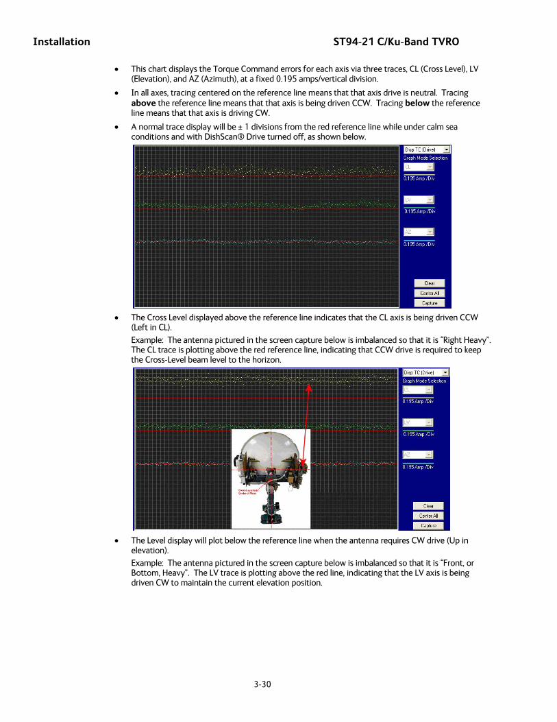
Installation ST94-21 C/Ku-Band TVRO
3-30
• This chart displays the Torque Command errors for each axis via three traces, CL (Cross Level), LV (Elevation), and AZ (Azimuth), at a fixed 0.195 amps/vertical division.
• In all axes, tracing centered on the reference line means that that axis drive is neutral. Tracing above the reference line means that that axis is being driven CCW. Tracing below the reference line means that that axis is driving CW.
• A normal trace display will be ± 1 divisions from the red reference line while under calm sea conditions and with DishScan® Drive turned off, as shown below.
• The Cross Level displayed above the reference line indicates that the CL axis is being driven CCW
(Left in CL).
Example: The antenna pictured in the screen capture below is imbalanced so that it is “Right Heavy”. The CL trace is plotting above the red reference line, indicating that CCW drive is required to keep the Cross-Level beam level to the horizon.
• The Level display will plot below the reference line when the antenna requires CW drive (Up in
elevation).
Example: The antenna pictured in the screen capture below is imbalanced so that it is “Front, or Bottom, Heavy”. The LV trace is plotting above the red line, indicating that the LV axis is being driven CW to maintain the current elevation position.
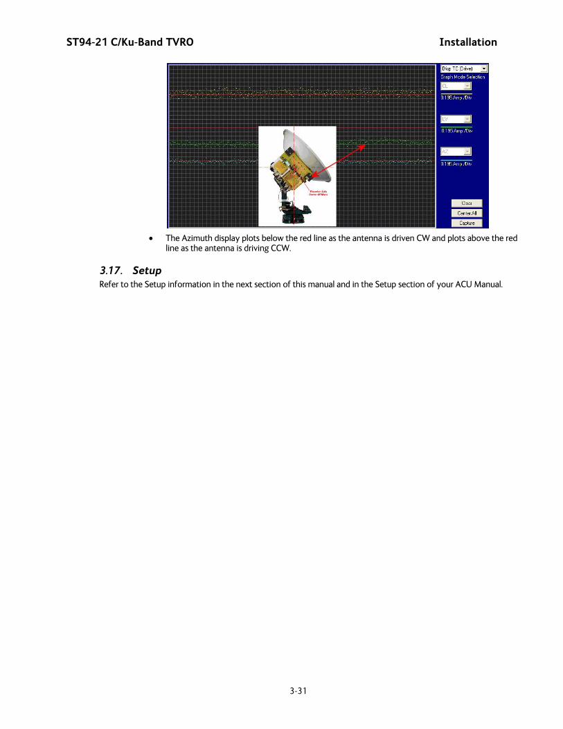
ST94-21 C/Ku-Band TVRO Installation
3-31
• The Azimuth display plots below the red line as the antenna is driven CW and plots above the red
line as the antenna is driving CCW.
3.17. Setup Refer to the Setup information in the next section of this manual and in the Setup section of your ACU Manual.

Installation ST94-21 C/Ku-Band TVRO
3-32
This Page Intentionally Left Blank
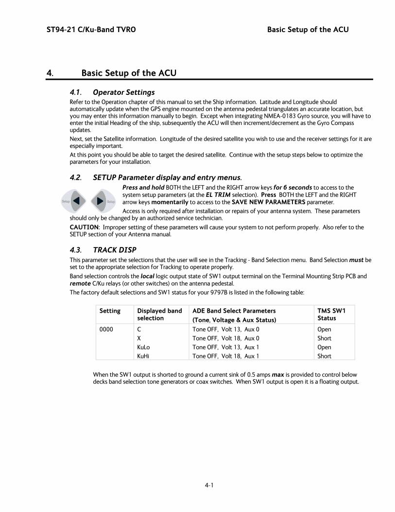
ST94-21 C/Ku-Band TVRO Basic Setup of the ACU
4-1
4. Basic Setup of the ACU
4.1. Operator Settings Refer to the Operation chapter of this manual to set the Ship information. Latitude and Longitude should automatically update when the GPS engine mounted on the antenna pedestal triangulates an accurate location, but you may enter this information manually to begin. Except when integrating NMEA-0183 Gyro source, you will have to enter the initial Heading of the ship, subsequently the ACU will then increment/decrement as the Gyro Compass updates.
Next, set the Satellite information. Longitude of the desired satellite you wish to use and the receiver settings for it are especially important.
At this point you should be able to target the desired satellite. Continue with the setup steps below to optimize the parameters for your installation.
4.2. SETUP Parameter display and entry menus. Press and hold BOTH the LEFT and the RIGHT arrow keys for 6 seconds to access to the system setup parameters (at the EL TRIM selection). Press BOTH the LEFT and the RIGHT arrow keys momentarily to access to the SAVE NEW PARAMETERS parameter.
Access is only required after installation or repairs of your antenna system. These parameters should only be changed by an authorized service technician.
CAUTION: Improper setting of these parameters will cause your system to not perform properly. Also refer to the SETUP section of your Antenna manual.
4.3. TRACK DISP This parameter set the selections that the user will see in the Tracking - Band Selection menu. Band Selection must be set to the appropriate selection for Tracking to operate properly.
Band selection controls the local logic output state of SW1 output terminal on the Terminal Mounting Strip PCB and remote C/Ku relays (or other switches) on the antenna pedestal.
The factory default selections and SW1 status for your 9797B is listed in the following table:
Setting Displayed band selection
ADE Band Select Parameters
(Tone, Voltage & Aux Status)
TMS SW1 Status
0000 C
X
KuLo
KuHi
Tone OFF, Volt 13, Aux 0
Tone OFF, Volt 18, Aux 0
Tone OFF, Volt 13, Aux 1
Tone OFF, Volt 18, Aux 1
Open
Short
Open
Short
When the SW1 output is shorted to ground a current sink of 0.5 amps max is provided to control below decks band selection tone generators or coax switches. When SW1 output is open it is a floating output.

Basic Setup of the ACU ST94-21 C/Ku-Band TVRO
4-2
4.4. ACU Factory Default Parameter Settings – STxxx-21 Series Antennas The following table shows the factory default parameters for the ACU interfaced to a ST-21 Series Antenna. You may need to optimize some of these parameters. Refer to the individual parameter setting information in the Setup section of your ACU manual.
PARAMETER C-Band
DishScan®
Ku-Band
DishScan®
My Parameters
EL TRIM 0
AZ TRIM 0
AUTO THRES 100
EL STEP SIZE 0
AZ STEP SIZE 0
STEP INTEGRAL 0
SEARCH INC 30 15
SEARCH LIMIT 200 100
SEARCH DELAY 30
SWEEP INC 0040
SYSTEM TYPE 0005
GYRO TYPE 2
POL TYPE 72
POL OFFSET 30
POL SCALE 90
AZ LIMIT 1 0
AZ LIMIT 2 0
EL LIMIT 12 0
AZ LIMIT 3 0
AZ LIMIT 4 0
EL LIMIT 34 0
AZ LIMIT 5 0
AZ LIMIT 6 0
EL LIMIT 56 0
5V OFFSET 0
5V SCALE 0
TRACK DISP Refer to TRACK DISP parameter
TX POLARITY 2
REMOTE PARAMETER ST94-21 ST94-21 ST144-21
PCU Configuration Number N0xxx 212 213 208
DishScan Phase/Gain N7xxx 149 149 192
Home Flag Offset N6xxx 000 000 000

ST94-21 C/Ku-Band TVRO Setup – Ships Gyro Compass
5-1
5. Setup – Ships Gyro Compass The Ships Gyro Compass connection provides true heading (heading of the ship relative to true North) input to the system. This allows the ACU to target the antenna to a “true” Azimuth position to acquire any desired satellite.
After targeting this input keeps the antenna stabilized in Azimuth (keeps it pointed at the targeted satellite Azimuth). In normal operation when viewing and ADMC recording in DacRemP, the “Relative Azimuth” trace should do exactly equal & opposite to whatever the Heading trace does and the “Azimuth” trace should stay flat.
In normal operation the heading display in the ACU should at all times be the same value as the reading on the Gyro Compass itself (this is also referred to as Gyro Following.).
If the ACU is not Following the Ships Gyro Compass correctly (un-erringly) refer to the Troubleshooting Gyro Compass Problems.
5.1. GYRO TYPE The GYRO TYPE parameter selects the type of gyro compass interface signal, the appropriate hardware connections and the ratio of the expected input signal for ship turning compensation. Default GYRO TYPE parameter for all systems is 0002 so that the ACU will properly follow for Step-By-Step or NMEA gyro signals.
If the Ships Gyro Compass output is Synchro, or there is NO Gyro Compass, the GYRO TYPE parameter must be set correctly to properly read and follow the Ships Gyro Compass signal that is being provided. The acceptable settings are:
362 for 360:1 Synchro with S/D Converter
90 for 90:1 Synchro with S/D Converter
36 for 36:1 Synchro with S/D Converter
2 for Step-By-Step gyro or NMEA gyro
1 for 1:1 Synchro with S/D Converter
0 for No Gyro linear AZ Search Mode (No Heading input available)
5.2. Updating the GYRO TYPE parameter To manually update, press the LEFT arrow key to bring the cursor under the least significant character. Continue to move the cursor until the desired character to be edited is underscored (selected). Use the UP or DOWN arrow keys to increment or decrement the selected character.
Use the LEFT or RIGHT arrow key to move the cursor left or right to select other characters to modify. When you are finished modifying press ENTER to execute the new value OR press NEXT to abort and exit setup mode.
When you are finished making parameter changes, go to the SAVE NEW PARAMETERS display to save the changes you have made.
5.3. If There is NO Ships Gyro Compass Without heading input to the system the ACU will NOT be able to target, or stay stabilized ON, a “true” azimuth pointing angle. This will make satellite acquisition much more difficult and the true azimuth value that any given satellite should be at will not be displayed correctly.
This mode of operation is NOT recommended for ships. A better solution would be to provide a Satellite Compass (multiple GPS Antenna device) to provide true heading input to the ACU. These devices are readily available and are much less expensive than a Gyro Compass.
If there is NO Gyro Compass (ie on a large stationary rig which is anchored to the ocean floor) set the GYRO TYPE parameter to 0000, the SWEEP INC parameter to 0047 and SAT REF (Satellite Reference Mode) MUST be turned ON. This combination of settings will cause “No Gyro” Search pattern to be use to find the desired satellite (refer to the setup – Searching lesson).

Setup – Ships Gyro Compass ST94-21 C/Ku-Band TVRO
5-2
This Page Intentionally Left Blank
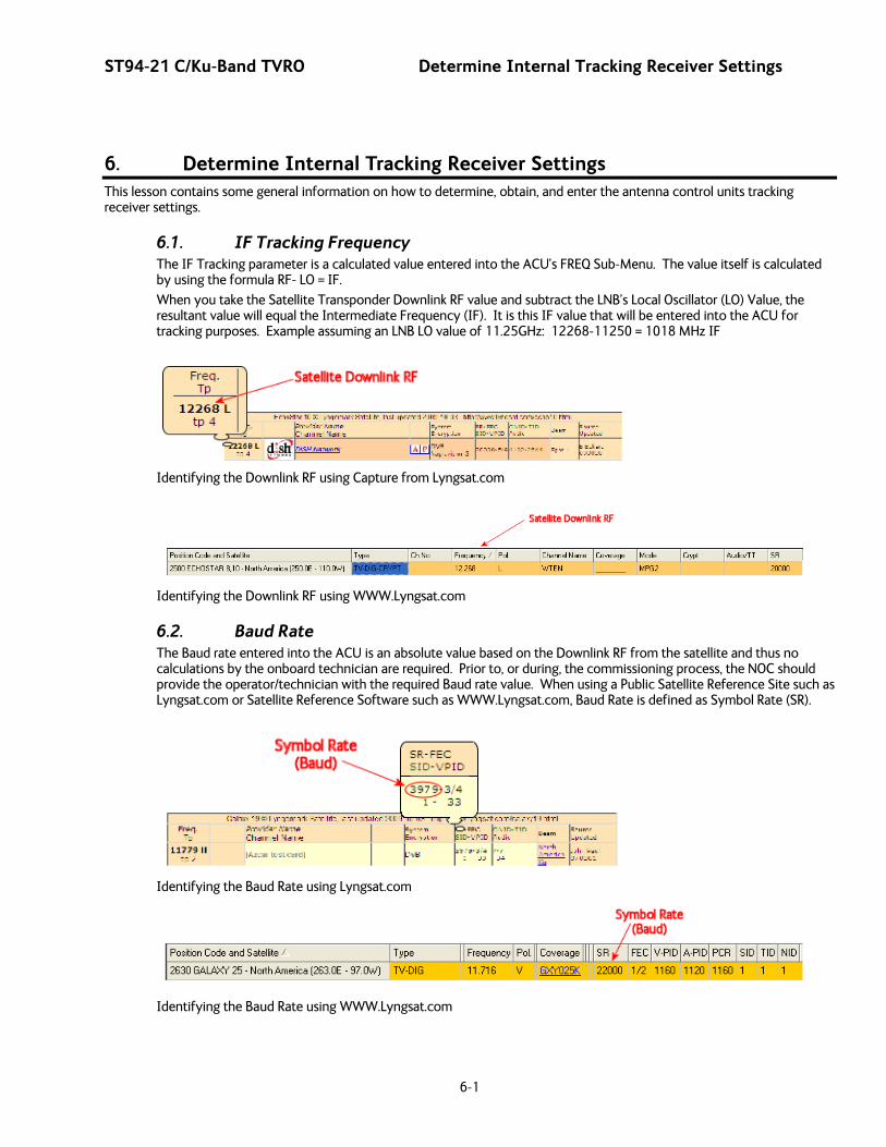
ST94-21 C/Ku-Band TVRO Determine Internal Tracking Receiver Settings
6-1
6. Determine Internal Tracking Receiver Settings This lesson contains some general information on how to determine, obtain, and enter the antenna control units tracking receiver settings.
6.1. IF Tracking Frequency The IF Tracking parameter is a calculated value entered into the ACU’s FREQ Sub-Menu. The value itself is calculated by using the formula RF- LO = IF.
When you take the Satellite Transponder Downlink RF value and subtract the LNB’s Local Oscillator (LO) Value, the resultant value will equal the Intermediate Frequency (IF). It is this IF value that will be entered into the ACU for tracking purposes. Example assuming an LNB LO value of 11.25GHz: 12268-11250 = 1018 MHz IF
Identifying the Downlink RF using Capture from Lyngsat.com
Identifying the Downlink RF using WWW.Lyngsat.com
6.2. Baud Rate The Baud rate entered into the ACU is an absolute value based on the Downlink RF from the satellite and thus no calculations by the onboard technician are required. Prior to, or during, the commissioning process, the NOC should provide the operator/technician with the required Baud rate value. When using a Public Satellite Reference Site such as Lyngsat.com or Satellite Reference Software such as WWW.Lyngsat.com, Baud Rate is defined as Symbol Rate (SR).
Identifying the Baud Rate using Lyngsat.com
Identifying the Baud Rate using WWW.Lyngsat.com

Determine Internal Tracking Receiver Settings ST94-21 C/Ku-Band TVRO
6-2
6.3. FEC
6.3.1. DVB Receiver The Forward Error Correction rate entered into the ACU is an absolute value based on the Downlink RF from the satellite and thus no calculations are required. Prior to, or during, the commissioning process, the NOC should provide the operator/technician with the required FEC Rate. When using a Public Satellite Reference Site such as Lyngsat.com or Satellite Reference Software such as WWW.Lyngsat.com, the Forward Error Correction rate is abbreviated as FEC.
Identifying the FEC Rate using Lyngsat.com
Identifying the FEC Rate using WWW.Lyngsat.com
6.4. Tone
6.4.1. TVRO Applications The Tone state entered into the ACU will be toggled either on or off. Although there are many possibilities of uses of a 22 KHz tone, in a Sea Tel TVRO antenna system it is primarily used for below decks band selection (Tone On = Ku Hi-Band and Tone Off = Ku Lo-Band) and is based on the Downlink RF value from the satellite. An RF Downlink value is less than 11699 is considered to be Ku-Lo band and tone must be turned “Off” for proper port selection of the Multiswitch. An RF Downlink value greater than 11700 is Ku-Band Hi-band and tone must be turned “On” for proper port selection of the Multiswitch. When using a Public Satellite Reference Site such as Lyngsat.com or Satellite Reference Software such as WWW.Lyngsat.com, refer to the Frequency value to determine whether tone is required, or not, for tracking purposes. Refer to the IF Tracking Frequency graphics above to identify a satellite transponders Downlink RF value.
6.5. Volt
6.5.1. TVRO Application The Voltage setting in the ACU is a selection of one of four receiver options and is based on the Downlink RF Polarization from the satellite. In a TVRO application, receiver voltage is used for proper port (receive polarization) selection. The polarization type should be provided to the operator/technician by the NOC prior to, or during the commissioning process. When using a Public Satellite Reference Site such as Lyngsat.com or Satellite Reference Software such as WWW.Lyngsat.com, Polarization is abbreviated “Pol.”
Receiver Voltage Selection Receiver Voltage output
Reference Website Abbreviation
RHCP (Right Hand Circular Polarization) 13VDC R
LHCP (Left Hand Circular Polarization) 18VDC L
VERT (Vertical Linear Polarization) 13VDC V
HORZ (Horizontal Linear Polarization) 18VDC H
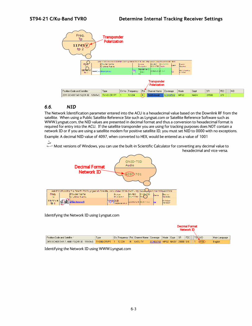
ST94-21 C/Ku-Band TVRO Determine Internal Tracking Receiver Settings
6-3
6.6. NID The Network Identification parameter entered into the ACU is a hexadecimal value based on the Downlink RF from the satellite. When using a Public Satellite Reference Site such as Lyngsat.com or Satellite Reference Software such as WWW.Lyngsat.com, the NID values are presented in decimal format and thus a conversion to hexadecimal format is required for entry into the ACU. If the satellite transponder you are using for tracking purposes does NOT contain a network ID or if you are using a satellite modem for positive satellite ID, you must set NID to 0000 with no exceptions.
Example: A decimal NID value of 4097, when converted to HEX, would be entered as a value of 1001
Most versions of Windows, you can use the built-in Scientific Calculator for converting any decimal value to hexadecimal and vice-versa.
Identifying the Network ID using Lyngsat.com
Identifying the Network ID using WWW.Lyngsat.com

Determine Internal Tracking Receiver Settings ST94-21 C/Ku-Band TVRO
6-4
This Page Intentionally Left Blank
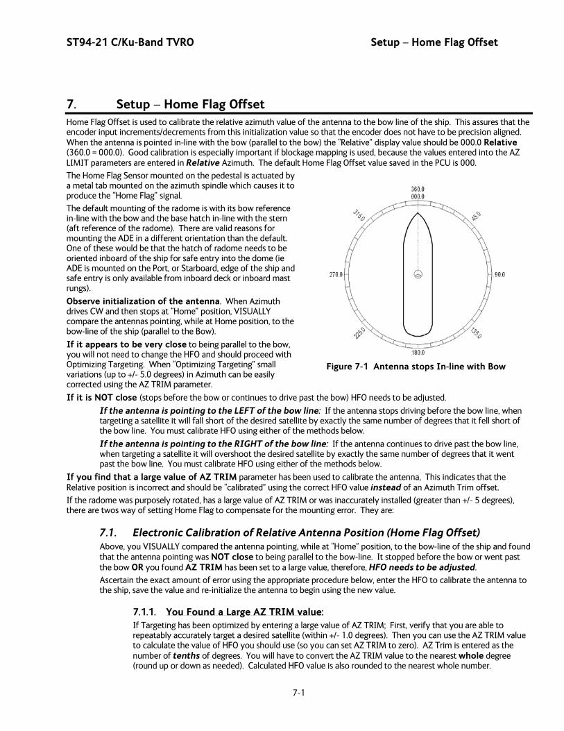
ST94-21 C/Ku-Band TVRO Setup – Home Flag Offset
7-1
Figure 7-1 Antenna stops In-line with Bow
7. Setup – Home Flag Offset Home Flag Offset is used to calibrate the relative azimuth value of the antenna to the bow line of the ship. This assures that the encoder input increments/decrements from this initialization value so that the encoder does not have to be precision aligned. When the antenna is pointed in-line with the bow (parallel to the bow) the “Relative” display value should be 000.0 Relative (360.0 = 000.0). Good calibration is especially important if blockage mapping is used, because the values entered into the AZ LIMIT parameters are entered in Relative Azimuth. The default Home Flag Offset value saved in the PCU is 000.
The Home Flag Sensor mounted on the pedestal is actuated by a metal tab mounted on the azimuth spindle which causes it to produce the “Home Flag” signal.
The default mounting of the radome is with its bow reference in-line with the bow and the base hatch in-line with the stern (aft reference of the radome). There are valid reasons for mounting the ADE in a different orientation than the default. One of these would be that the hatch of radome needs to be oriented inboard of the ship for safe entry into the dome (ie ADE is mounted on the Port, or Starboard, edge of the ship and safe entry is only available from inboard deck or inboard mast rungs).
Observe initialization of the antenna. When Azimuth drives CW and then stops at “Home” position, VISUALLY compare the antennas pointing, while at Home position, to the bow-line of the ship (parallel to the Bow).
If it appears to be very close to being parallel to the bow, you will not need to change the HFO and should proceed with Optimizing Targeting. When “Optimizing Targeting” small variations (up to +/- 5.0 degrees) in Azimuth can be easily corrected using the AZ TRIM parameter.
If it is NOT close (stops before the bow or continues to drive past the bow) HFO needs to be adjusted.
If the antenna is pointing to the LEFT of the bow line: If the antenna stops driving before the bow line, when targeting a satellite it will fall short of the desired satellite by exactly the same number of degrees that it fell short of the bow line. You must calibrate HFO using either of the methods below.
If the antenna is pointing to the RIGHT of the bow line: If the antenna continues to drive past the bow line, when targeting a satellite it will overshoot the desired satellite by exactly the same number of degrees that it went past the bow line. You must calibrate HFO using either of the methods below.
If you find that a large value of AZ TRIM parameter has been used to calibrate the antenna, This indicates that the Relative position is incorrect and should be “calibrated” using the correct HFO value instead of an Azimuth Trim offset.
If the radome was purposely rotated, has a large value of AZ TRIM or was inaccurately installed (greater than +/- 5 degrees), there are twos way of setting Home Flag to compensate for the mounting error. They are:
7.1. Electronic Calibration of Relative Antenna Position (Home Flag Offset) Above, you VISUALLY compared the antenna pointing, while at “Home” position, to the bow-line of the ship and found that the antenna pointing was NOT close to being parallel to the bow-line. It stopped before the bow or went past the bow OR you found AZ TRIM has been set to a large value, therefore, HFO needs to be adjusted.
Ascertain the exact amount of error using the appropriate procedure below, enter the HFO to calibrate the antenna to the ship, save the value and re-initialize the antenna to begin using the new value.
7.1.1. You Found a Large AZ TRIM value: If Targeting has been optimized by entering a large value of AZ TRIM; First, verify that you are able to repeatably accurately target a desired satellite (within +/- 1.0 degrees). Then you can use the AZ TRIM value to calculate the value of HFO you should use (so you can set AZ TRIM to zero). AZ Trim is entered as the number of tenths of degrees. You will have to convert the AZ TRIM value to the nearest whole degree (round up or down as needed). Calculated HFO value is also rounded to the nearest whole number.

Setup – Home Flag Offset ST94-21 C/Ku-Band TVRO
7-2
Figure 7-2 Antenna stopped before the Bow
Figure 7-3 Antenna stops past the Bow
If AZ TRIM was a plus value: HFO = (TRIM / 360) x 255 Example: AZ TRIM was 0200 (plus 20 degrees). HFO = (20/360) x 255 = (0.0556) x 255 = 14.16 round off to 14. Set, and Save, HFO to 014 using the “To Enter the HFO value” procedure below.
If AZ TRIM was a negative value: HFO = ((360-TRIM) / 360)) x 255 Example: AZ TRIM = -0450 (minus 45 degrees). HFO = ((360 – 45) / 360)) x 255 = (315 / 360) x 255 = 0.875 x 255 = 223.125 round of to 223. Set, and Save, HFO to 223 using the “To Enter the HFO value” procedure below.
7.1.2. You Observe “Home” Pointing is LEFT of the Bow-line: 1. In this example, I observe that the
Home position is short of the bow line.
2. I estimate that it is about 45 degrees.
3. I target my desired satellite and record the Calculated Azimuth to be 180.5.
4. I drive UP (I estimated that I will need to go UP about 45 degrees) and finally find my desired satellite.
5. Turn tracking ON to let the ACU peak the signal up. When peaked, the Azimuth is 227.0 degrees.
6. I subtract Calculated from Peak (227 – 0180.5 = 46.5) and difference is 46.5 degrees.
7. I can calculate what the correct value for the Home position of the antenna by subtracting (because “home” was to the left of bow) this difference of 46.5 from the bow line position 360.0. Therefore “home” should be 313.5 Relative.
8. I now calculate the HFO = (313.5 / 360) x 255 = 0.87 x 255 = 222.06 which I round off to 222.
9. I set, and Save, HFO to 222 using the “To Enter the HFO value” procedure below. After I re-initialize the relative position of the antenna is now calibrated.
10. If there is a small amount of error remaining, use AZ TRIM in the Optimizing Targeting procedure to correct it.
7.1.3. You Observe “Home” Pointing is RIGHT of the Bow-line: 1. In this example, I observe that the
Home position is past the bow line.
2. I estimate that it is about 90 degrees.
3. I target my desired satellite and record the Calculated Azimuth to be 180.0.
4. I drive DOWN (I estimated that I will need to go DOWN about 89 degrees) and finally find my desired satellite.
5. Turn tracking ON to let the ACU peak the signal up. When peaked, the Azimuth is 90.0 degrees.
6. I subtract Calculated from Peak (180.0 – 90.0 = 90.0) and difference is 90.0 degrees.
7. I can calculate what the correct value for the Home position of the antenna by adding (because
ST94-21 C/Ku-Band TVRO Setup – Home Flag Offset
7-3
“home” was to the right of bow) this difference of 09.0 to the bow line position 000.0. Therefore “home” should be 90.0 Relative.
8. I now calculate the HFO = = ((90.0) / 360)) x 255 = 0.25 x 255 = 63.75 which I round off to 64.
9. I set, and Save, HFO to 222 using the “To Enter the HFO value” procedure below. After I re-initialize the relative position of the antenna is now calibrated.
10. If there is a small amount of error remaining, I will use AZ TRIM in the Optimizing Targeting procedure to correct it.
7.1.4. To Enter the HFO value in the DAC_2202: To enter the calculated HFO value, press & hold both LEFT and RIGHT arrows for six seconds to enter the parameter menu at the EL TRIM parameter window. Press DOWN arrow key numerous times (about 21) until you have selected the REMOTE COMMAND window.
In the REMOTE COMMAND window, press the LEFT arrow key until you have underscored the left most character in the displayed value (ie the A in "A0000"). Use the UP/DOWN arrow keys to increment/decrement the underscored character until it is upper case N (“N0000” should appear in the command window). Press the RIGHT arrow key to move the cursor under the most significant digit, then use the UP arrow key to increment it to a value of 6 (the display is now “N6000”). Set the three digits to the right of the 6 to the three digit HFO value from 000 to 255 (corresponding to 0 to 360 degrees) that you calculated above. Use the LEFT/RIGHT keys to underscore the desired digit(s) then use the UP/DOWN arrow keys to increment/decrement the underscored value. When you have finished editing the display value, press ENTER to send the HFO value command to the PCU (but it is not save yet).
If you want to find out what the current HFO value is key in N6999 and hit ENTER. When completed, you must save the desired HFO value. Press ENTER several times to select the REMOTE PARAMETERS display. Press the LEFT or RIGHT arrow key to enter writing mode and then press the ENTER to save the HFO value in the PCUs NVRAM.
EXAMPLE: In the “You Observe “Home” Pointing is LEFT of the Bow-line” example above, the HFO calculated was 222. To enter this value:
1. Set the Remote Command value to "N6222".
2. Press ENTER to send this HFO to the PCU. The display should now show "N0222".
3. When completed, you must save the desired HFO value. Press ENTER several times to select the REMOTE PARAMETERS display. Press the LEFT or RIGHT arrow key to enter writing mode and then press the ENTER to save the HFO value in the PCUs NVRAM.
You must drive the antenna CW in azimuth until the home switch is actuated, or re-initialize the antenna to begin using the new HFO value you have entered and saved. To re-initialize the antenna from the REMOTE COMMAND window of the ACU;
4. Press UP arrow key several times to return to the REMOTE COMMAND display.
5. Press the LEFT or RIGHT arrow key to enter edit mode. Use the LEFT/RIGHT and UP/DOWN arrow keys to set the character and digits to "^0090" and then press the ENTER key.
This resets the PCU on the antenna. The antenna will reinitialize with this command (Performs a similar function as a power reset of the antenna) and the new home flag offset value will be used to calibrate the Relative position of the antenna.

Setup – Home Flag Offset ST94-21 C/Ku-Band TVRO
7-4
This Page Intentionally Left Blank

ST94-21 C/Ku-Band TVRO Setup – Targeting
8-1
8. Setup – Targeting Optimizing the targeting of the antenna to land on or near a desired satellite (within +/-1 degree) is outlined below.
8.1. AUTO TRIM The Auto Trim function will automatically calculate and set the required Azimuth and Elevation trim offset parameters required to properly calibrate the antennas display to the mechanical angle of the antenna itself, while peaked ON satellite. It will also calculate, and set, the proper Auto-Threshold value for this system to use on the desired/targeted satellite.
To enable this function, the Antenna MUST be actively tracking the satellite with positive SAT ID and elevation of the antenna must be less than 83 degrees and the ACU must NOT be set for Inclined Orbit Search. After locating the satellite, with Tracking ON, wait at least 30 seconds before performing the AUTO TRIM feature, this will allow sufficient time for the antenna to peak up on signal. It is equally important that you verify that the system is tracking the CORRECT satellite (verify video is produced on the Televisions in a TVRO system or verify a RX lock indication on the satellite modem in a VSAT system).
While in the AUTO TRIM sub-menu, press the LEFT arrow key to bring start the calibration procedure, the display should read AUTO TRIM SETUP, press the ENTER key to submit. AUTO TRIM SAVED will be displayed, indicating the proper AZ and EL trims were submitted to RAM. This does not save these parameters to NVRAM, in order to save to memory, continue down through the setup mode parameters until the SETUP SAVE NEW PARAMETERS sub menu is displayed. Press the RIGHT arrow and then press the ENTER key. The display should now report that the parameters were saved. From the AUTO TRIM SETUP screen, press the NEXT key (DAC2202) without hitting ENTER to escape this screen without submitting the new AZ and EL Trim values.
NOTE: AUTO TRIM LOCKED will be displayed on the front panel, indicating that the AUTO TRIM Feature is NOT allowed if all of these conditions are not met:
The ACU must be actively tracking a satellite (AGC above threshold) and
The ACU must have positive SAT ID (internal NID match or external RX lock received from the Satellite Modem) and
The elevation angle of the antenna must be LESS than 75 degrees and
The ACU must NOT be set for Inclined Orbit Search.
8.2. Manually Optimizing Targeting First, assure that all of your Ship & Satellite settings in the ACU are correct.
1. Target the desired satellite, immediately turn Tracking OFF, and record the Azimuth and Elevation positions in the “ANTENNA“ display of the ACU (these are the Calculated positions).
2. Turn Tracking ON, allow the antenna to “Search” for the targeted satellite and assure that it has acquired (and peaks up on) the satellite that you targeted.
3. Allow several minutes for the antenna to “peak” on the signal, and then record the Azimuth and Elevation positions while peaked on satellite (these are the Peak positions). Again, assure that it has acquired the satellite that you targeted!
4. Subtract the Peak Positions from the Calculated Positions to determine the amount of Trim which is required. Refer to the ACU Setup information to key in the required value of Elevation Trim.
5. Continue with Azimuth trim, then re-target the satellite several times to verify that targeting is now driving the antenna to a position that is within +/- 1.0 degrees of where the satellite signal is located.
EXAMPLE: The ACU targets to an Elevation position of 30.0 degrees and an Azimuth position of 180.2 (Calculated), you find that Peak Elevation while ON your desired satellite is 31.5 degrees and Peak Azimuth is 178.0. You would enter an EL TRIM value of –1.5 degrees (displayed as -0015) and an AZ TRIM of +2.2 degrees (displayed as 0022). After these trims values had been set, your peak on satellite Azimuth and Elevation displays would be very near 180.2 and 30.0 respectively.
Setup – Targeting ST94-21 C/Ku-Band TVRO
8-2
8.3. EL TRIM Elevation trim offset parameter is entered in tenths of degrees. Adjusts display to correct for antenna alignment errors or imbalances in the antenna system. Increase number to increase display. Refer to “Optimizing Targeting” in the Setup section of your antenna manual.
To update: While in the EL TRIM sub-menu, press the LEFT arrow key to bring the cursor under the ones digit. Press the UP or DOWN arrow key to increment or decrement the selected digit. Minus values are entered by decrementing below zero. Use the LEFT or RIGHT arrow key to move the cursor left or right to select other characters to modify. When you are finished modifying press ENTER to execute the new value OR press NEXT to abort and exit setup mode.
Continue with Azimuth trim, then re-target the satellite several times to verify that targeting is now driving the antenna to a position that is within +/- 1.0 degrees of where the satellite signal is located.
8.4. AZ TRIM Azimuth trim offset parameter is entered in tenths of degrees. Offsets true azimuth angle display to compensate for installation alignment errors when used with Ships Gyro Compass input reference. Azimuth Trim does not affect REL azimuth reading. Increase number to increase displayed value. Refer to “Optimizing Targeting” in the Setup section of your antenna manual.
To update: While in the AZ TRIM sub-menu, press the LEFT arrow key to bring the cursor under the ones digit. Press the UP or DOWN arrow key to increment or decrement the selected digit. Minus values are entered by decrementing below zero. Use the LEFT or RIGHT arrow key to move the cursor left or right to select other characters to modify. When you are finished modifying press ENTER to execute the new value OR press NEXT to abort and exit setup mode.
Then re-target the satellite several times to verify that targeting is now driving the antenna to a position that is within +/- 1.0 degrees of where the satellite signal is located.
8.5. SAVE NEW PARAMETERS Parameters that have been changed are only temporarily changed until they are SAVED. If changes are made and not stored, they will still be effective but will be lost when power is removed or the RESET key is pressed. Simultaneously press, and quickly release the LEFT & RIGHT arrow keys to access “SAVE NEW PARAMETERS” directly from any other menu display. Verify that the change(s) you have made is/are correct and then select “SAVE NEW PARAMETERS”. Press UP arrow and then ENTER to save any recent changes into the ACUs NVRAM for permanent storage.
ST94-21 C/Ku-Band TVRO Setup – Searching
9-1
9. Setup – Searching
9.1. Searching Operation The ACU will initiate an automated search pattern after AGC falls below the current Threshold setting (indicates that satellite signal has been lost). The SEARCH DELAY parameter sets the amount of delay, in seconds, that the ACU will wait after AGC has fallen below the threshold value before it starts a search.
Search can be initiated manually by pressing the NEXT key as many times as required to access the SETUP menu, then press the ENTER Key to access the SEARCH sub-menu and then press the UP arrow key (starts a search from the current antenna position). While in the SEARCH sub-menu, pressing the DOWN arrow key will stop the current search.
Search is terminated automatically when the AGC level exceeds the threshold value and Tracking begins.
The ACU can be configured to use one of three search patterns. Each of the search patterns are described below. Each description includes information about the settings involved in configuring the ACU to select that particular pattern and the values that those settings would be set to, to optimize the pattern for your antenna model and the frequency band being used.
The dimensions and timing of the search pattern are determined by the SETUP parameters SEARCH INC, SEARCH LIMIT, SEARCH DELAY and SWEEP INC. Search is also affected by the Threshold and the internal receiver settings under the Satellite menu. To change any one of these parameters, refer to “Changing the Search Parameters” procedures below.
All three search patterns are conducted in a two-axis pattern consisting of alternate movements in azimuth and elevation or along the polarization angle. The size and direction of the movements are increased and reversed every other time resulting in an increasing spiral pattern as shown.
9.1.1. Default Standard (Box) Search Pattern The factory default search pattern in the ACU is a standard “box” pattern. You configure the ACU to use this pattern by using the following settings:
SEARCH INC - set to the default value for the frequency band that your antenna model is currently being used for (typically 15 counts).
SEARCH LIMIT – initially set to the default value. After targeting has been optimized, the search limit can be adjusted if desired.
SEARCH DELAY – default, or any number of seconds from 1-255 that you would prefer that the ACU wait before starting an automatic search.
SWEEP INC – default value (this parameter is not used in this search pattern).
GYRO TYPE – must NOT be set to zero.
SAT REF mode – It is normally OFF as long as you have good gyro compass input. It MUST be OFF when the elevation angle is greater than 75 degrees. It Must be ON if you are experiencing frequent, or constant, gyro read errors (error code 0001).
Target any satellite longitude value which includes even tenths digit values (ie SAT 101.0 W or SAT 101.2 W). If the desired satellite longitude includes an odd tenths digit, you must round it up, or down, one tenth to make the tenths digit EVEN. The Antenna Control Unit calculates the Azimuth, Elevation and Polarization values it will target the antenna. Initially the antenna will go to a position that is 8 degrees above the calculated elevation, until Azimuth and Polarization have had time to complete adjustment. Then the antenna will drive down to the calculated elevation, which is the “Start” of the search pattern in the graphic below.
The antenna will then search up in azimuth one Search Increment, search up one Search Increment in elevation, search down two Search Increments in azimuth, search down two Search Increments in elevation, etc until Search Limit is reached. When the end of the search pattern is reached, the ACU will retarget the antenna to the start point shown in the graphic below.
If the desired signal is found (AND network lock is achieved in the satellite modem) at this position, or anywhere within the search pattern, the ACU will terminate search and go into Tracking mode. If the desired signal is not found the ACU will wait SEARCH DELAY seconds and then begin the search pattern again. This cycle will repeat until the desired satellite signal is found or the operator intervenes.
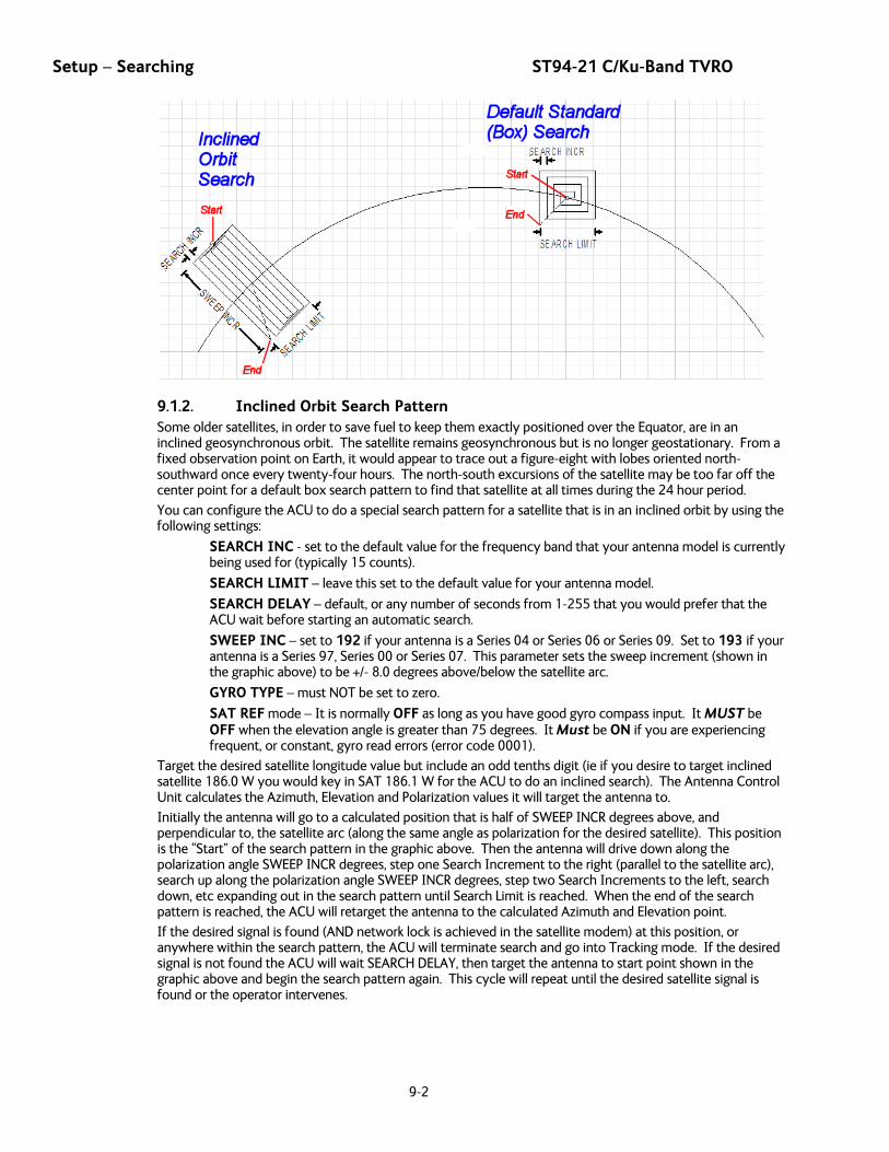
Setup – Searching ST94-21 C/Ku-Band TVRO
9-2
9.1.2. Inclined Orbit Search Pattern Some older satellites, in order to save fuel to keep them exactly positioned over the Equator, are in an inclined geosynchronous orbit. The satellite remains geosynchronous but is no longer geostationary. From a fixed observation point on Earth, it would appear to trace out a figure-eight with lobes oriented north-southward once every twenty-four hours. The north-south excursions of the satellite may be too far off the center point for a default box search pattern to find that satellite at all times during the 24 hour period.
You can configure the ACU to do a special search pattern for a satellite that is in an inclined orbit by using the following settings:
SEARCH INC - set to the default value for the frequency band that your antenna model is currently being used for (typically 15 counts).
SEARCH LIMIT – leave this set to the default value for your antenna model.
SEARCH DELAY – default, or any number of seconds from 1-255 that you would prefer that the ACU wait before starting an automatic search.
SWEEP INC – set to 192 if your antenna is a Series 04 or Series 06 or Series 09. Set to 193 if your antenna is a Series 97, Series 00 or Series 07. This parameter sets the sweep increment (shown in the graphic above) to be +/- 8.0 degrees above/below the satellite arc.
GYRO TYPE – must NOT be set to zero.
SAT REF mode – It is normally OFF as long as you have good gyro compass input. It MUST be OFF when the elevation angle is greater than 75 degrees. It Must be ON if you are experiencing frequent, or constant, gyro read errors (error code 0001).
Target the desired satellite longitude value but include an odd tenths digit (ie if you desire to target inclined satellite 186.0 W you would key in SAT 186.1 W for the ACU to do an inclined search). The Antenna Control Unit calculates the Azimuth, Elevation and Polarization values it will target the antenna to.
Initially the antenna will go to a calculated position that is half of SWEEP INCR degrees above, and perpendicular to, the satellite arc (along the same angle as polarization for the desired satellite). This position is the “Start” of the search pattern in the graphic above. Then the antenna will drive down along the polarization angle SWEEP INCR degrees, step one Search Increment to the right (parallel to the satellite arc), search up along the polarization angle SWEEP INCR degrees, step two Search Increments to the left, search down, etc expanding out in the search pattern until Search Limit is reached. When the end of the search pattern is reached, the ACU will retarget the antenna to the calculated Azimuth and Elevation point.
If the desired signal is found (AND network lock is achieved in the satellite modem) at this position, or anywhere within the search pattern, the ACU will terminate search and go into Tracking mode. If the desired signal is not found the ACU will wait SEARCH DELAY, then target the antenna to start point shown in the graphic above and begin the search pattern again. This cycle will repeat until the desired satellite signal is found or the operator intervenes.

ST94-21 C/Ku-Band TVRO Setup – Searching
9-3
9.1.3. No Gyro Search Pattern If the ship does not have a gyro compass to use as a heading input to the Antenna Control Unit, you may manually key in the actual heading of the vessel and then re-target the desired satellite, every time you need to re-target a satellite, or configure the ACU to do a “No Gyro Search Pattern”.
You configure the ACU to use this pattern by using the following settings:
SEARCH INC - set to the default value for the frequency band that your antenna model is currently being used for (typically 15 counts).
SEARCH LIMIT – leave this set to the default value.
SEARCH DELAY – default, or any number of seconds from 1-255 that you would prefer that the ACU wait before starting an automatic search.
SWEEP INC – Larger antennas should have slower speeds and smaller antennas should have faster speeds:
Larger antennas should have slower speeds set to 0047 (= 5 degrees/second) for 2.4M to 3.6M antenna systems).
Mid size antennas can be driven a little faster, set to 0063 (= 8 degrees/second) for 2M antennas models).
Smaller antennas should have faster speeds, set to 0079 (= 18 degrees/second) for all 0.8M to 1.5M antenna models).
GYRO TYPE – MUST be set to zero for this search pattern.
SAT REF mode – MUST be ON for this search pattern.
Target any satellite longitude value which includes even tenths digit values (ie SAT 101.0 W or SAT 101.2 W). If the desired satellite longitude includes an odd tenths digit, you must round it up, or down, one tenth to make the tenths digit EVEN. The Antenna Control Unit calculates the Azimuth, Elevation and Polarization values it will use to target the antenna. However, without heading input, the ACU cannot target a “true azimuth” position (relative to true North). It will target the antenna to the calculated elevation and a repeatable “Start” relative azimuth position. In Series 04 antennas this relative position will be 90 degrees away from the nearest mechanical stop. In all other antennas it will be 000 degrees relative.
Initially the antenna will go to the “Start” relative azimuth position at the calculated elevation. Then the antenna will search up 450 degrees in azimuth, search up one Search Increment in elevation, search down 450 degrees in azimuth, search down two Search Increments in elevation, etc until Search Limit is reached. When the end of the search pattern is reached, the ACU will retarget the antenna back to the start point shown in the graphic below.
If the desired signal is found (AND network lock is achieved in the satellite modem) at this position, or anywhere within the search pattern, the ACU will terminate search and go into Tracking mode. If the desired signal is not found the ACU will wait SEARCH DELAY seconds and then begin the search pattern again. This cycle will repeat until the desired satellite signal is found or the operator intervenes.
Setup – Searching ST94-21 C/Ku-Band TVRO
9-4
9.2. Changing the Search Parameters The information above described what some of these parameters need to be set to for a specific search pattern. Below are some additional pieces of information on the other parameters and the steps to change any one of these parameters.
9.2.1. AUTO THRES Sets offset of AGC tracking threshold above the average noise floor. Units are in A/D counts, approximately 20 counts/dB. A setting of 0 disables auto threshold, therefore, the operator would have to manually enter a threshold value.
When AUTO THRESHOLD is enabled (any value between 1-255), the ACU automatically re-sets the AGC tracking threshold whenever the antenna Targets (AZ, EL or SAT) or Searches. The new AGC threshold is set to the average signal level input (approximate background noise level) plus the AUTO THRES offset value. EXAMPLE: If the Noise Floor off satellite is 1000 counts of AGC and Auto Threshold is set to 100, Threshold will be set to approximately 1100 after the antenna has finished targeting or Searching.
To change the Automatic Threshold value OR manually set threshold; Note the Peak “on satellite” AGC value, move EL and note the “off satellite” (Noise Floor) AGC value. Calculate the Difference between Peak AGC and Noise Floor AGC. AUTO THRES should be set to 1/3 (to ½) of the Difference. This will usually be around 100 counts (3 dB) for a typical antenna configuration. Changes to this parameter may be required based on carrier tracking frequency, possible adjacent satellite, or ambient interference with desired satellite.
To manually update, press the LEFT arrow key to bring the cursor up under the least significant character. Continue to move the cursor until the desired character to be edited is underscored (selected). Use the UP or DOWN arrow keys to increment or decrement the selected character.
Use the LEFT or RIGHT arrow key to move the cursor left or right to select other characters to modify. When you are finished modifying press ENTER to execute the new value OR press NEXT to abort and exit setup mode.
9.2.2. EL STEP SIZE For proper DishScan® operation this parameter must be set to factory default value of 0000.
To manually update, press the LEFT arrow key to bring the cursor up under the least significant character. Continue to move the cursor until the desired character to be edited is underscored (selected). Use the UP or DOWN arrow keys to increment or decrement the selected character.
Use the LEFT or RIGHT arrow key to move the cursor left or right to select other characters to modify. When you are finished modifying press ENTER to execute the new value OR press NEXT to abort and exit setup mode.
9.2.3. AZ STEP SIZE For proper DishScan® operation this parameter must be set to factory default value of 0000.
To manually update, press the LEFT arrow key to bring the cursor up under the least significant character. Continue to move the cursor until the desired character to be edited is underscored (selected). Use the UP or DOWN arrow keys to increment or decrement the selected character.
Use the LEFT or RIGHT arrow key to move the cursor left or right to select other characters to modify. When you are finished modifying press ENTER to execute the new value OR press NEXT to abort and exit setup mode.
9.2.4. STEP INTEGRAL For proper DishScan® operation this parameter must be set to factory default value of 0000.
To manually update, press the LEFT arrow key to bring the cursor under the least significant character. Continue to move the cursor until the desired character to be edited is underscored (selected). Use the UP or DOWN arrow keys to increment or decrement the selected character.
Use the LEFT or RIGHT arrow key to move the cursor left or right to select other characters to modify. When you are finished modifying press ENTER to execute the new value OR press NEXT to abort and exit setup mode.
ST94-21 C/Ku-Band TVRO Setup – Searching
9-5
9.2.5. SEARCH INC Sets size of search pattern increment. Units are in pedestal step resolution (24 steps per degree). The suggested setting is equal to the full 3dB beamwidth of your antenna. Default value is 30 these systems.
To manually update, press the LEFT arrow key to bring the cursor under the least significant character. Continue to move the cursor until the desired character to be edited is underscored (selected). Use the UP or DOWN arrow keys to increment or decrement the selected character.
Use the LEFT or RIGHT arrow key to move the cursor left or right to select other characters to modify. When you are finished modifying press ENTER to execute the new value OR press NEXT to abort and exit setup mode.
9.2.6. SEARCH LIMIT Sets the overall peak to peak size of the search pattern. Units are in pedestal step resolution (24 steps per degree). Default value is 200 for these systems.
After you have optimized your Targeting (refer to Optimizing Targeting) you may wish to reduce the size of the Search pattern to avoid Tracking on an adjacent satellite (ie set to 50% of its default value so that in the future it will only search half as far from your targeted position).
To manually update, press the LEFT arrow key to bring the cursor under the least significant character. Continue to move the cursor until the desired character to be edited is underscored (selected). Use the UP or DOWN arrow keys to increment or decrement the selected character.
Use the LEFT or RIGHT arrow key to move the cursor left or right to select other characters to modify. When you are finished modifying press ENTER to execute the new value OR press NEXT to abort and exit setup mode.
9.2.7. SEARCH DELAY Sets the time-out for automatic initiation of a search operation when the signal level (AGC) drops below threshold. Units are in seconds. Range is 0-255 seconds. Default setting is 30 seconds. A setting of 0 disables the automatic search initiation.
To manually update, press the LEFT arrow key to bring the cursor under the least significant character. Continue to move the cursor until the desired character to be edited is underscored (selected). Use the UP or DOWN arrow keys to increment or decrement the selected character.
To manually update, press the LEFT arrow key to bring the cursor under the least significant character. Continue to move the cursor until the desired character to be edited is underscored (selected). Use the UP or DOWN arrow keys to increment or decrement the selected character.
9.2.8. SWEEP INC This parameter MUST be set for the desired azimuth sweep speed of a No Gyro search or the sweep increment dimension of an Inclined Orbit search (refer to the search pattern information above).
To manually update, press the LEFT arrow key to bring the cursor under the least significant character. Continue to move the cursor until the desired character to be edited is underscored (selected). Use the UP or DOWN arrow keys to increment or decrement the selected character.
Use the LEFT or RIGHT arrow key to move the cursor left or right to select other characters to modify. When you are finished modifying press ENTER to execute the new value OR press NEXT to abort and exit setup mode.
9.3. SAVE NEW PARAMETERS Parameters that have been changed are only temporarily changed until they are SAVED. If changes are made and not stored, they will still be effective but will be lost when power is removed or the RESET key is pressed. Simultaneously press, and quickly release the LEFT & RIGHT arrow keys to access “SAVE NEW PARAMETERS” directly from any other menu display. Verify that the change(s) you have made is/are correct and then select “SAVE NEW PARAMETERS”. Press UP arrow and then ENTER to save any recent changes into the ACUs NVRAM for permanent storage.

Setup – Searching ST94-21 C/Ku-Band TVRO
9-6
This Page Intentionally Left Blank

ST94-21 C/Ku-Band TVRO Setup – Blockage & RF Radiation Hazard Zones
10-1
10. Setup – Blockage & RF Radiation Hazard Zones This section discusses how to set up blockage, or RF Radiation Hazard, zones.
10.1. Radiation Hazard and Blockage Mapping (AZ LIMIT parameters) The ACU can be programmed with relative azimuth sectors (zones) where blockage exists or where transmit power would endanger personnel who are frequently in that area. Your ACU software may allow you to set four zones or it will only three zones and include +5 volt polarization.
When the AZ LIMIT parameters are set to create these ZONES (up to four), several things happen when the antenna is within one of the zones:
1. Tracking continues as long as the AGC value is greater than the Threshold value. When the AGC value drops below Threshold, the antenna will wait “Search Delay” parameter amount of time and then re-target the satellite you targeted last (if 4 value is included in SYSTEM TYPE). Timeout and re-target will continue until the satellite is re-acquired and tracking can resume.
2. “BLOCKED” will be displayed in the TRACKING window wherever the antenna is inside one of the zones.
3. A contact closure to ground (or an open if the blockage logic is reversed – See SYSTEM TYPE 16 value) is provided on the SW2 terminal of the Terminal Mounting Strip. This Switch output provides a “Blocked”, “RF Radiation Hazard” or “FCC TX Mute” logic output. When the antenna exits the zone it will be on satellite, tracking and the SW2 logic contact closure will open.
The lower and upper limits are user programmable and are stored in NVRAM within the ACU parameter list.
AZ LIMIT 1 is the Lower Relative AZ limit (this is the more counter-clockwise of the two points, even if it is numerically larger). AZ LIMIT 2 is the Upper Relative AZ limit (the more clockwise of the two points) for pattern mapping of ZONE 1. Enter the elevation value that represents the top of the blockage between the two azimuth limit points in the EL LIMIT 12 parameter.
AZ LIMIT 3 is the Lower Relative AZ limit (CCW point) and AZ LIMIT 4 is the Upper Relative AZ limit (CW point) for pattern mapping of ZONE 2. Enter the elevation value that represents the top of the blockage between the two azimuth limit points in the EL LIMIT 34 parameter.
AZ LIMIT 5 is the Lower Relative AZ limit (CCW point) and AZ LIMIT 6 is the Upper Relative AZ limit (CW point) for pattern mapping of ZONE 3. Enter the elevation value that represents the top of the blockage between the two azimuth limit points in the EL LIMIT 56 parameter.
AZ LIMIT 7 is the Lower Relative AZ limit (CCW point) and AZ LIMIT 8 is the Upper Relative AZ limit (CW point) for pattern mapping of ZONE 4. Enter the elevation value that represents the top of the blockage between the two azimuth limit points in the EL LIMIT 78 parameter. If your ACU software includes 5 volt polarization you will not see these AZ & EL LIMIT parameters.
CAUTION: The Lower Relative AZ limit is the more counter-clockwise of the two points (even if it is numerically larger) and the Upper Relative AZ limit is the more clockwise of the two points. If you enter the two relative points incorrectly, Tracking and Searching will be adversely affected.
The ACU provides a contact closure to ground on the SW2 terminal of the Terminal Mounting Strip when the antenna is pointed within any one of the blockage/hazard zones or the system is searching, targeting, unwrapping or is mis-pointed by 0.5 degrees or more (FCC TX Mute function for Transmit/Receive systems only). The contact closure is a transistor switch with a current sinking capability of 0.5 Amp. Refer to “Functional Testing” for instructions on how to simulate a manual BLOCKED condition to test SW2 logic output.
When used as simple “BLOCKED” logic output for a single Sea Tel antenna, this output could be used to light a remote LED and/or sound a buzzer to alert someone that the antenna is blocked, and therefore signal is lost.
In a “Dual Antenna” installation, this logic output is also used to control a Dual Antenna Arbitrator panel to switch the TXIF & RXIF signals from Antenna “A” to Antenna “B” when Antenna “A” is blocked, and vice versa.
When used as simple “RF Radiation Hazard” logic output for a single Sea Tel TXRX antenna, this output could be used to suppress RF transmissions while the antenna is pointed where people would be harmed by the transmitted microwave RF power output. The SW2 output would be interfaced to the satellite modem to disable the TX output signal from the Satellite TXRX Modem whenever the antenna is within the RF Radiation Hazard zone(s).

Setup – Blockage & RF Radiation Hazard Zones ST94-21 C/Ku-Band TVRO
10-2
When used for “FCC TX Mute” logic output for a single Sea Tel TXRX antenna, this output is used to suppress RF transmissions whenever the antenna is mis-pointed 0.5 degrees or more, is blocked, searching, targeting or unwrapping. The SW2 output would be interfaced to the satellite modem to disable/mute the TX output signal from the Satellite TXRX Modem. When the mute condition is due to antenna mis-pointing, it will not un-mute until the pointing error of the antenna is within 0.2 degrees. The default output is contact closure to ground when the antenna is mis-pointed, therefore providing a ground to “Mute” the satellite modem from the SW2 terminal of the Terminal Mounting Strip. If your satellite modem requires an open to “Mute”, refer to SYSTEM TYPE parameter 16 value to reverse the output logic from the ACU.
Programming instructions:
Determine the Relative AZ positions where blockage, or RF Radiation Hazard, exists. This may be done by monitoring the received signal level and the REL display readings while the ship turns or by graphing the expected blockage pattern. Elevation of the antenna in normal use also must be taken into consideration. A Mast or other structure may cause blockage at low elevation angles, but may not cause blockage when the antenna is at higher elevation angles where it is able to look over the structure. Up to four zones may be mapped. Only zones which are needed should be mapped (in AZ LIMIT pairs).
In unlimited antenna systems the Relative position of the antenna must have been calibrated by properly setting the Home Flag Offset (HFO) value in the PCU. The HFO calibrates Relative to display 0000 when the antenna is pointed in-line with the bow of the boat/ship (parallel to the bow).
Convert the relative readings to AZ LIMIT/EL LIMIT values by multiplying by 10. Enter the beginning of the first blockage region as AZ LIMIT 1 and the end of the region (clockwise direction from AZ LIMIT 1) as AZ LIMIT 2 parameters in the ACU. If needed, repeat setting AZ LIMIT 3 & 4 for a second ZONE and then AZ LIMIT 5 & 6 if a third ZONE is needed. All unneeded zone AZ LIMIT pairs must be set to 0000. Set the upper elevation limit of each blockage zone (also entered in degrees multiplied by 10).
EXAMPLE 1 - Three blockage Zones: A ship has a Sea Tel antenna mounted on the port side and an Inmarsat antenna mounted on the starboard side. A mast forward, the Inmarsat antenna to starboard and an engine exhaust stack aft form the three zones where satellite signal is blocked (as shown in the graphic). In this example zone 1 is caused by the mast, zone 2 is from the Inmarsat antenna, zone 3 is from the stack and zone 4 is not needed:
ZONE 1 begins (AZ LIMIT 1) at 12 degrees Relative and ends (AZ LIMIT 2) at 18 degrees Relative. Multiply these Relative positions by 10. Enter AZ LIMIT 1 value of 0120 and AZ LIMIT 2 value of 0180. In this case the mast height only causes blockage up to an elevation of 50 degrees, so we set EL LIMIT 12 to 0500. If the antenna is between these two AZ Limit points but the elevation is greater than 50 degrees, the antenna will no longer be blocked.
ZONE 2 begins (AZ LIMIT 3) at 82 degrees Relative and ends (AZ LIMIT 4) at 106 degrees Relative. Multiply these Relative positions by 10. Enter AZ LIMIT 3 value of 0820 and AZ LIMIT 4 value of 1060. In this case the Inmarsat antenna height only causes blockage up to an elevation of 12 degrees, so we set EL LIMIT 34 to 0120. If the antenna is between these two AZ Limit points but the elevation is greater than 12 degrees, the antenna will no longer be blocked.
ZONE 3 begins (AZ LIMIT 5) at 156 degrees Relative and ends (AZ LIMIT 6) at 172 degrees Relative. Multiply these Relative positions by 10. Enter AZ LIMIT 5 value of 1560 and AZ LIMIT 6 value of 1720. In this case the stack antenna height only causes blockage up to an elevation of 36 degrees, so we set EL LIMIT 56 to 0360. If the antenna is between these two AZ Limit points but the elevation is greater than 36 degrees, the antenna will no longer be blocked.
ZONE 4 is not needed. Enter AZ LIMIT 7 value of 0000 and AZ LIMIT 8 value of 0000. Set EL LIMIT 78 to 0000. If your ACU software includes 5 volt polarization you will not see these AZ & EL LIMIT parameters.
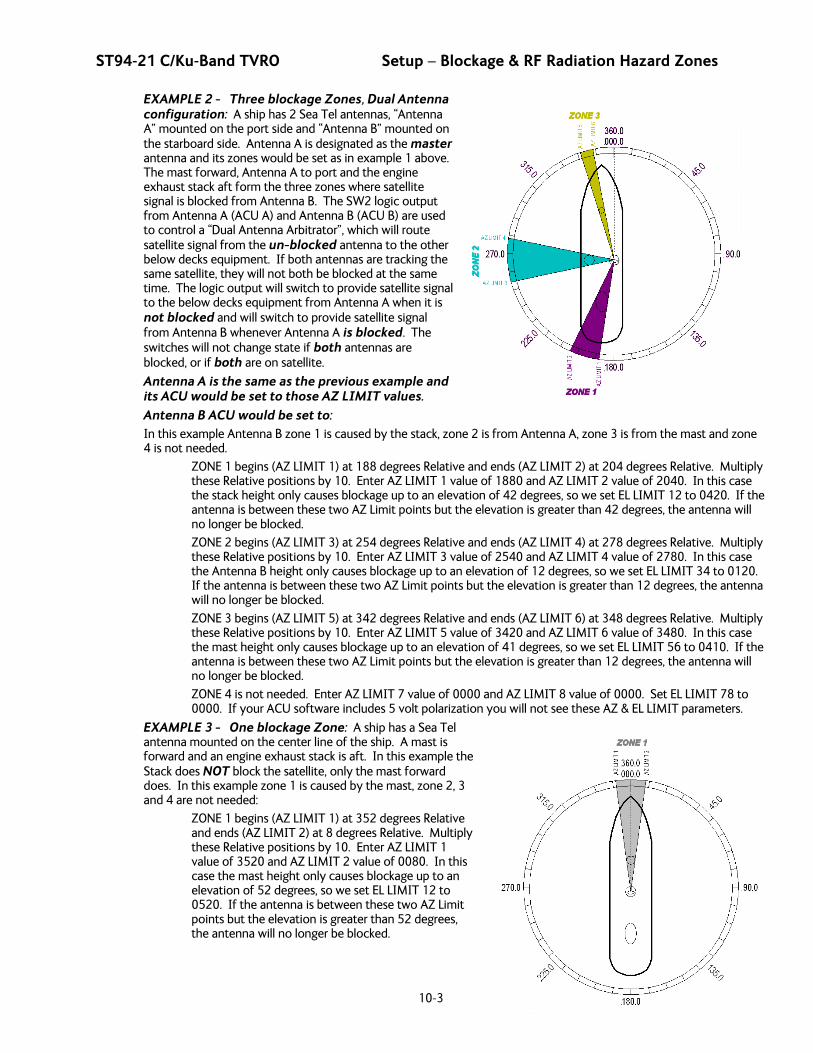
ST94-21 C/Ku-Band TVRO Setup – Blockage & RF Radiation Hazard Zones
10-3
EXAMPLE 2 - Three blockage Zones, Dual Antenna configuration: A ship has 2 Sea Tel antennas, “Antenna A” mounted on the port side and “Antenna B” mounted on the starboard side. Antenna A is designated as the master antenna and its zones would be set as in example 1 above. The mast forward, Antenna A to port and the engine exhaust stack aft form the three zones where satellite signal is blocked from Antenna B. The SW2 logic output from Antenna A (ACU A) and Antenna B (ACU B) are used to control a “Dual Antenna Arbitrator”, which will route satellite signal from the un-blocked antenna to the other below decks equipment. If both antennas are tracking the same satellite, they will not both be blocked at the same time. The logic output will switch to provide satellite signal to the below decks equipment from Antenna A when it is not blocked and will switch to provide satellite signal from Antenna B whenever Antenna A is blocked. The switches will not change state if both antennas are blocked, or if both are on satellite.
Antenna A is the same as the previous example and its ACU would be set to those AZ LIMIT values.
Antenna B ACU would be set to: In this example Antenna B zone 1 is caused by the stack, zone 2 is from Antenna A, zone 3 is from the mast and zone 4 is not needed.
ZONE 1 begins (AZ LIMIT 1) at 188 degrees Relative and ends (AZ LIMIT 2) at 204 degrees Relative. Multiply these Relative positions by 10. Enter AZ LIMIT 1 value of 1880 and AZ LIMIT 2 value of 2040. In this case the stack height only causes blockage up to an elevation of 42 degrees, so we set EL LIMIT 12 to 0420. If the antenna is between these two AZ Limit points but the elevation is greater than 42 degrees, the antenna will no longer be blocked.
ZONE 2 begins (AZ LIMIT 3) at 254 degrees Relative and ends (AZ LIMIT 4) at 278 degrees Relative. Multiply these Relative positions by 10. Enter AZ LIMIT 3 value of 2540 and AZ LIMIT 4 value of 2780. In this case the Antenna B height only causes blockage up to an elevation of 12 degrees, so we set EL LIMIT 34 to 0120. If the antenna is between these two AZ Limit points but the elevation is greater than 12 degrees, the antenna will no longer be blocked.
ZONE 3 begins (AZ LIMIT 5) at 342 degrees Relative and ends (AZ LIMIT 6) at 348 degrees Relative. Multiply these Relative positions by 10. Enter AZ LIMIT 5 value of 3420 and AZ LIMIT 6 value of 3480. In this case the mast height only causes blockage up to an elevation of 41 degrees, so we set EL LIMIT 56 to 0410. If the antenna is between these two AZ Limit points but the elevation is greater than 12 degrees, the antenna will no longer be blocked.
ZONE 4 is not needed. Enter AZ LIMIT 7 value of 0000 and AZ LIMIT 8 value of 0000. Set EL LIMIT 78 to 0000. If your ACU software includes 5 volt polarization you will not see these AZ & EL LIMIT parameters.
EXAMPLE 3 - One blockage Zone: A ship has a Sea Tel antenna mounted on the center line of the ship. A mast is forward and an engine exhaust stack is aft. In this example the Stack does NOT block the satellite, only the mast forward does. In this example zone 1 is caused by the mast, zone 2, 3 and 4 are not needed:
ZONE 1 begins (AZ LIMIT 1) at 352 degrees Relative and ends (AZ LIMIT 2) at 8 degrees Relative. Multiply these Relative positions by 10. Enter AZ LIMIT 1 value of 3520 and AZ LIMIT 2 value of 0080. In this case the mast height only causes blockage up to an elevation of 52 degrees, so we set EL LIMIT 12 to 0520. If the antenna is between these two AZ Limit points but the elevation is greater than 52 degrees, the antenna will no longer be blocked.
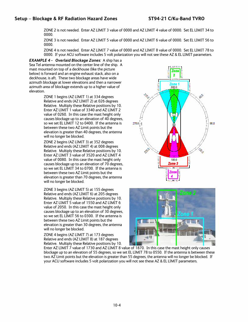
Setup – Blockage & RF Radiation Hazard Zones ST94-21 C/Ku-Band TVRO
10-4
ZONE 2 is not needed. Enter AZ LIMIT 3 value of 0000 and AZ LIMIT 4 value of 0000. Set EL LIMIT 34 to 0000.
ZONE 3 is not needed. Enter AZ LIMIT 5 value of 0000 and AZ LIMIT 6 value of 0000. Set EL LIMIT 56 to 0000.
ZONE 4 is not needed. Enter AZ LIMIT 7 value of 0000 and AZ LIMIT 8 value of 0000. Set EL LIMIT 78 to 0000. If your ACU software includes 5 volt polarization you will not see these AZ & EL LIMIT parameters.
EXAMPLE 4 - Overlaid Blockage Zones: A ship has a Sea Tel antenna mounted on the center line of the ship. A mast mounted on top of a deckhouse (like the picture below) is forward and an engine exhaust stack, also on a deckhouse, is aft. These two blockage areas have wide azimuth blockage at lower elevations and then a narrower azimuth area of blockage extends up to a higher value of elevation.
ZONE 1 begins (AZ LIMIT 1) at 334 degrees Relative and ends (AZ LIMIT 2) at 026 degrees Relative. Multiply these Relative positions by 10. Enter AZ LIMIT 1 value of 3340 and AZ LIMIT 2 value of 0260. In this case the mast height only causes blockage up to an elevation of 40 degrees, so we set EL LIMIT 12 to 0400. If the antenna is between these two AZ Limit points but the elevation is greater than 40 degrees, the antenna will no longer be blocked.
ZONE 2 begins (AZ LIMIT 3) at 352 degrees Relative and ends (AZ LIMIT 4) at 008 degrees Relative. Multiply these Relative positions by 10. Enter AZ LIMIT 3 value of 3520 and AZ LIMIT 4 value of 0080. In this case the mast height only causes blockage up to an elevation of 70 degrees, so we set EL LIMIT 34 to 0700. If the antenna is between these two AZ Limit points but the elevation is greater than 70 degrees, the antenna will no longer be blocked.
ZONE 3 begins (AZ LIMIT 5) at 155 degrees Relative and ends (AZ LIMIT 6) at 205 degrees Relative. Multiply these Relative positions by 10. Enter AZ LIMIT 5 value of 1550 and AZ LIMIT 6 value of 2050. In this case the mast height only causes blockage up to an elevation of 30 degrees, so we set EL LIMIT 56 to 0300. If the antenna is between these two AZ Limit points but the elevation is greater than 30 degrees, the antenna will no longer be blocked.
ZONE 4 begins (AZ LIMIT 7) at 173 degrees Relative and ends (AZ LIMIT 8) at 187 degrees Relative. Multiply these Relative positions by 10. Enter AZ LIMIT 7 value of 1730 and AZ LIMIT 8 value of 1870. In this case the mast height only causes blockage up to an elevation of 55 degrees, so we set EL LIMIT 78 to 0550. If the antenna is between these two AZ Limit points but the elevation is greater than 55 degrees, the antenna will no longer be blocked. If your ACU software includes 5 volt polarization you will not see these AZ & EL LIMIT parameters.
ST94-21 C/Ku-Band TVRO Setup
11-1
11. Setup Below are basic steps to guide you in setting up the ACU for your specific antenna pedestal. Assure that the Antenna Pedestal (ADE) has been properly installed before proceeding. Refer to the Setup section of you ACU manual for additional parameter setting details.
11.1. Operator Settings Refer to the Operation chapter of this manual to set the Ship information. Latitude and Longitude should automatically update when the GPS engine mounted above decks triangulates an accurate location, but you may enter this information manually to begin. If your gyro source is providing Heading information in any format other than NMEA-0183 format, you will have to enter in the initial Ship’s Heading position, the Gyro Compass will then keep the ACU updated.
Set the Satellite information, for the satellite you will be using. The receiver settings are especially important. At this point you should be able to target the desired satellite. Continue with the setup steps below to optimize the parameters for your installation.
11.2. Optimizing Targeting (Auto Trim) The following feature requires your antenna have GSR2 minimum software versions installed. First, assure that all of your Ship & Satellite settings in the ACU are correct. Target and, if required manually locate the desired satellite. Allow 1 to 2 minutes for the antenna to “peak” on the signal. Verify positive satellite identification, in a TVRO system verify either Receive NID or that at least one Television is producing video, in a VSAT system verify receive lock indication on the satellite modem.
Access the ACU Setup Mode Parameter “AUTO TRIM”, Press the UP arrow and then press Enter.
Drive the antenna completely off satellite (Target and Azimuth value of 0)
Retarget the satellite and verify the system peaks on satellite with positive satellite identification within 1 minute.
Access the ACU Setup Modes “SAVE NEW PARAMETERS”, Press the UP arrow and then press Enter
11.3. Optimizing Targeting (Manually) First, assure that all of your Ship & Satellite settings in the ACU are correct. Target the desired satellite, immediately turn Tracking OFF, and record the Azimuth and Elevation positions in the “ANTENNA“ display of the ACU (these are the Calculated positions). Turn Tracking ON, allow the antenna to “Search” for the targeted satellite and assure that it has acquired (and peaks up on) the satellite that you targeted. Allow several minutes for the antenna to “peak” on the signal, and then record the Azimuth and Elevation positions while peaked on satellite (these are the Peak positions). Again, assure that it has acquired the satellite that you targeted!
Subtract the Peak Positions from the Calculated Positions to determine the amount of Trim which is required. Refer to the ACU Setup information to key in the required value of Elevation Trim. Continue with Azimuth trim, then re-target the satellite several times to verify that targeting is now driving the antenna to a position that is within +/- 1.0 degrees of where the satellite signal is located.
EXAMPLE: The ACU targets to an Elevation position of 30.0 degrees and an Azimuth position of 180.2 (Calculated), you find that Peak Elevation while ON your desired satellite is 31.5 degrees and Peak Azimuth is 178.0. You would enter an EL TRIM value of –1.5 degrees and an AZ TRIM of +2.2 degrees. After these trims values had been set, your peak on satellite Azimuth and Elevation displays would be very near 180.2 and 30.0 respectively.
11.4. Radiation Hazard and Blockage Mapping (AZ LIMIT parameters) This system may be programmed with relative azimuth and elevation sectors (zones) where blockage exists or where transmit power would endanger personnel who are frequently in that area.
Refer to your ACU Manual for instructions on programming of these zones.
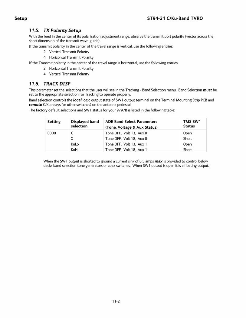
Setup ST94-21 C/Ku-Band TVRO
11-2
11.5. TX Polarity Setup With the feed in the center of its polarization adjustment range, observe the transmit port polarity (vector across the short dimension of the transmit wave-guide).
If the transmit polarity in the center of the travel range is vertical, use the following entries:
2 Vertical Transmit Polarity
4 Horizontal Transmit Polarity
If the Transmit polarity in the center of the travel range is horizontal, use the following entries:
2 Horizontal Transmit Polarity
4 Vertical Transmit Polarity
11.6. TRACK DISP This parameter set the selections that the user will see in the Tracking - Band Selection menu. Band Selection must be set to the appropriate selection for Tracking to operate properly.
Band selection controls the local logic output state of SW1 output terminal on the Terminal Mounting Strip PCB and remote C/Ku relays (or other switches) on the antenna pedestal.
The factory default selections and SW1 status for your 9797B is listed in the following table:
Setting Displayed band selection
ADE Band Select Parameters
(Tone, Voltage & Aux Status)
TMS SW1 Status
0000 C
X
KuLo
KuHi
Tone OFF, Volt 13, Aux 0
Tone OFF, Volt 18, Aux 0
Tone OFF, Volt 13, Aux 1
Tone OFF, Volt 18, Aux 1
Open
Short
Open
Short
When the SW1 output is shorted to ground a current sink of 0.5 amps max is provided to control below decks band selection tone generators or coax switches. When SW1 output is open it is a floating output.

ST94-21 C/Ku-Band TVRO Functional Testing
12-1
12. Functional Testing If not already ON, Turn ON the Power switch on the front panel of the ACU.
12.1. ACU / Antenna System Check 1. Press RESET on the ACU front panel to initialize the system. Verify the display shows "SEA TEL INC -
MASTER" and the ACU software version number. Wait 10 seconds for the display to change to "SEA TEL INC - REMOTE" and the PCU software version number.
2. If the display shows "REMOTE INITIALIZING” wait for approximately 2 minutes for the antenna to complete initialization and report the Antenna Model and PCU software version. If “REMOTE NOT RESPONDING" is displayed, refer to the Troubleshooting Section of this manual.
3. Press the NEXT key repeatedly to display the Ship, Satellite, Antenna and Status menu displays. This verifies that the displays change in the correct response to the keys.
12.2. Latitude/Longitude Auto-Update check This verifies that the GPS position information is automatically updating..
1. Press the NEXT key repeatedly to display the Ship menu. Press ENTER to access edit mode and view the current Latitude value.
2. Press the LEFT arrow key to bring the cursor up under the ones digit, press UP and then hit ENTER. The display should immediately show a latitude value one degree higher, but then will be overwritten within several seconds (back to the previous value) by the GPS engine.
This test does not need to be repeated in the Longitude menu.
12.3. Ship Heading – Gyro Compass Following Check This verifies that the Heading display is actually following the Ships Gyro Compass.
1. Press the NEXT key repeatedly to display the Ship menu. If the boat is underway, monitor the Heading value to verify that the display changes in the correct response to the Gyro Compass input (Heading value should always be exactly the same as the Gyro Compass repeater value).
2. If the ship is NOT underway, most ships will turn +/- 1-2 degrees at the pier, monitor the Heading value to verify that the display changes in the correct response to the Gyro Compass input (Heading value should always be exactly the same as the Gyro Compass repeater value).
12.4. Azimuth & Elevation Drive This verifies that the antenna moves in the correct response to the keys.
1. Press the NEXT key several times to display the Antenna menu.
2. Press the TRACK key to toggle Tracking OFF. Press the UP arrow key repeatedly and verify that the antenna moves up in elevation.
3. Press the DOWN arrow key repeatedly and verify that the antenna moves down in elevation.
4. Press the RIGHT arrow key repeatedly and verify that the antenna moves up (CW) in azimuth.
5. Press the LEFT arrow key repeatedly and verify that the antenna moves down (CCW) in azimuth.
12.5. Four Quadrant Tracking Test This verifies that the antenna moves in the correct response to the keys, that Tracking is signaling correctly and that the Tracking commands are being carried out (antenna drives to peak).
1. Verify antenna is locked onto and tracking a satellite
2. Press the NEXT key several times to display the Antenna menu.
3. Note the current peak AGC value. Press the Tracking key to toggle Tracking OFF, press the UP arrow key repeatedly to move the antenna up in elevation until AGC falls about 100 counts. Turn Tracking ON and verify that the antenna moves back down in elevation and that the AGC rises to its’ previous high value.
Functional Testing ST94-21 C/Ku-Band TVRO
12-2
4. Note the current peak AGC value. Press the Tracking key to toggle Tracking OFF, press the DOWN arrow key repeatedly to move the antenna down in elevation until AGC falls about 100 counts. Turn Tracking ON and verify that the antenna moves back up in elevation and that the AGC rises to its’ previous high value.
5. Note the current peak AGC value. Press the Tracking key to toggle Tracking OFF, press the RIGHT arrow key repeatedly to move the antenna up in azimuth until AGC falls about 100 counts. Turn Tracking ON and verify that the antenna moves back down in azimuth and that the AGC rises to its’ previous high value.
6. Note the current peak AGC value. Press the Tracking key to toggle Tracking OFF, press the LEFT arrow key repeatedly to move the antenna down in azimuth until AGC falls about 100 counts. Turn Tracking ON and verify that the antenna moves back up in azimuth and that the AGC rises to its’ previous high value.
12.6. Blockage Simulation Test Blockage output function is used to modify the behavior of Tracking and Searching when there is a known blockage zone. The ACU provides a contact closure to ground on the SW2 terminal of the Terminal Mounting Strip when the antenna is pointed within any one of the blockage/hazard zones or the system is searching, targeting, unwrapping or is mis-pointed by 0.5 degrees or more (FCC TX Mute function for Transmit/Receive systems only). The contact closure is a transistor switch with a current sinking capability of 0.5 Amp. This logic output control signal is used for:
• When used as simple “BLOCKED” logic output for a single Sea Tel antenna, this output could be used to light a remote LED and/or sound a buzzer to alert someone that the antenna is blocked, and signal is lost.
• In a “Dual Antenna” installation, this logic output(s) is used to control Dual Antenna Arbitrator panel of coax switches to switch the source inputs to the matrix switch from Antenna “A” to Antenna “B”, and vice versa.
• When used as simple “RF Radiation Hazard” logic output for a single Sea Tel TX/RX antenna, this output could be used to suppress RF transmissions while the antenna is pointed where people would be harmed by the transmitted microwave RF power output. The SW2 output would be interfaced to the satellite modem to disable the TX output signal from the Satellite TXRX Modem whenever the antenna is within the RF Radiation Hazard zone(s).
• When used for “FCC TX Mute” logic output for a single Sea Tel TX/RX antenna, this output could be used to suppress RF transmissions whenever the antenna is mis-pointed 0.5 degrees or more, is blocked, searching, targeting or unwrapping. The SW2 output would be interfaced to the satellite modem to disable/mute the TX output signal from the Satellite TX/RX Modem. When the mute condition is due to antenna mis-pointing, it will not un-mute until the pointing error of the antenna is within 0.2 degrees. The default output is contact closure to ground when the antenna is mis-pointed, therefore provides a ground to “Mute” the satellite modem on the SW2 terminal of the Terminal Mounting Strip. If your satellite modem requires an open to “Mute”, refer to SYSTEM TYPE parameter 16 value to reverse the output logic from the ACU.
To Test the blockage function:
1. Press the NEXT key until you are at the Status menu. Press ENTER to access the Tracking menu.
2. Press the RIGHT arrow key to bring up and move the cursor to the far right. Press the UP arrow to simulate a manual BLOCKED condition. BLOCKED will appear in the Tracking display.
3. Verify that SW2 terminal shorts to ground (or open circuit if you have SYSTEM TYPE configured to reverse the output logic) and that the external alarms actuate OR the Dual Antenna Arbitrator coax switches toggle (if antenna B is not blocked) OR the Satellite Modem TX is disabled/muted.
4. Press the LEFT arrow key and then press the UP arrow key to turn the simulated blocked condition OFF. BLOCKED will disappear from the Tracking display.
5. Verify that SW2 terminal is open circuit (or ground if you have logic reversed) and that the external alarms deactivate OR the Satellite Modem TX is un-muted. The Dual Antenna Arbitrator coax switches should not toggle until you manually block Antenna B ACU.
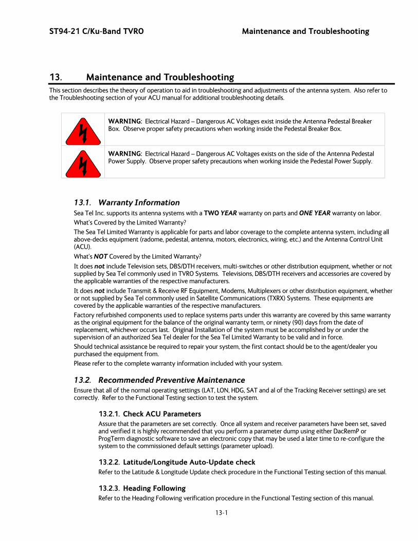
ST94-21 C/Ku-Band TVRO Maintenance and Troubleshooting
13-1
13. Maintenance and Troubleshooting This section describes the theory of operation to aid in troubleshooting and adjustments of the antenna system. Also refer to the Troubleshooting section of your ACU manual for additional troubleshooting details.
WARNING: Electrical Hazard – Dangerous AC Voltages exist inside the Antenna Pedestal Breaker Box. Observe proper safety precautions when working inside the Pedestal Breaker Box.
WARNING: Electrical Hazard – Dangerous AC Voltages exists on the side of the Antenna Pedestal Power Supply. Observe proper safety precautions when working inside the Pedestal Power Supply.
13.1. Warranty Information Sea Tel Inc. supports its antenna systems with a TWO YEAR warranty on parts and ONE YEAR warranty on labor.
What’s Covered by the Limited Warranty?
The Sea Tel Limited Warranty is applicable for parts and labor coverage to the complete antenna system, including all above-decks equipment (radome, pedestal, antenna, motors, electronics, wiring, etc.) and the Antenna Control Unit (ACU).
What’s NOT Covered by the Limited Warranty?
It does not include Television sets, DBS/DTH receivers, multi-switches or other distribution equipment, whether or not supplied by Sea Tel commonly used in TVRO Systems. Televisions, DBS/DTH receivers and accessories are covered by the applicable warranties of the respective manufacturers.
It does not include Transmit & Receive RF Equipment, Modems, Multiplexers or other distribution equipment, whether or not supplied by Sea Tel commonly used in Satellite Communications (TXRX) Systems. These equipments are covered by the applicable warranties of the respective manufacturers.
Factory refurbished components used to replace systems parts under this warranty are covered by this same warranty as the original equipment for the balance of the original warranty term, or ninety (90) days from the date of replacement, whichever occurs last. Original Installation of the system must be accomplished by or under the supervision of an authorized Sea Tel dealer for the Sea Tel Limited Warranty to be valid and in force.
Should technical assistance be required to repair your system, the first contact should be to the agent/dealer you purchased the equipment from.
Please refer to the complete warranty information included with your system.
13.2. Recommended Preventive Maintenance Ensure that all of the normal operating settings (LAT, LON, HDG, SAT and al of the Tracking Receiver settings) are set correctly. Refer to the Functional Testing section to test the system.
13.2.1. Check ACU Parameters Assure that the parameters are set correctly. Once all system and receiver parameters have been set, saved and verified it is highly recommended that you perform a parameter dump using either DacRemP or ProgTerm diagnostic software to save an electronic copy that may be used a later time to re-configure the system to the commissioned default settings (parameter upload).
13.2.2. Latitude/Longitude Auto-Update check Refer to the Latitude & Longitude Update check procedure in the Functional Testing section of this manual.
13.2.3. Heading Following Refer to the Heading Following verification procedure in the Functional Testing section of this manual.
Maintenance and Troubleshooting ST94-21 C/Ku-Band TVRO
13-2
13.2.4. Azimuth & Elevation Drive Refer to the Azimuth & Elevation Drive check procedure in the Functional Testing section of this manual.
13.2.5. Test Tracking Refer to the four quadrant Tracking check procedure in the Functional Testing section of this manual.
13.2.6. Visual Inspection - Radome & Pedestal Conduct a good, thorough, visual inspection of the radome and antenna pedestal. Visually inspect the inside surface of the radome top and of the antenna pedestal. Look for water or condensation, rust or corrosion, white fiberglass powder residue, loose wiring connections, loose hardware, loose or broken belts or any other signs of wear or damage.
1. Radome Inspection - All the radome flanges are properly sealed to prevent wind, saltwater spray and rain from being able to enter the radome. Re-seal any open (“leaky”) areas with marine approved silicone sealant. If heavy condensation, or standing water, is found inside the radome, isolate and seal the leak, and then dry out the radome. Small (1/8 inch) holes may be drilled in the base pan of the radome to allow standing water to “weep” out.
2. Antenna Pedestal Inspection - The shock/vibration springs and/or wire rope Isolators should not be frayed, completely compressed, or otherwise damaged. The plated and painted parts should not be rusted or corroded. The harnesses should not be frayed and all the connectors should be properly fastened and tightened. All hardware should be tight (no loose assemblies or counter-weights). Replace, re-coat, repair and/or tighten as necessary.
13.2.7. Mechanical Checks Turn the pedestal power supply OFF
1. Inspect inside of radome for signs that the dish or feed have been rubbing against the inside of the fiberglass radome.
2. Rotate the pedestal through its full range of azimuth motion. The antenna should rotate freely and easily with light finger pressure.
3. Rotate the pedestal through full range of elevation rotation. The antenna should rotate freely and easily with light finger pressure.
4. Rotate the pedestal through full range of cross-level rotation. The antenna should rotate freely and easily with light finger pressure.
5. Rotate the level cage through the full 90 degrees of rotation from CCW stop to CW stop. The level cage antenna should rotate freely and easily with light finger pressure. Attached cables should not cause the cage to spring back more that a few degrees from either stop when released.
6. Inspect all drive belts for wear (black dust on/under the area of the belt).
7. Inspect AZ Drive chain. IF chain is beginning to show signs of rust or corrosion, apply a light coat of light duty oil to the chain. Wipe excess oil off to leave a light coating on the chain. DO NOT over-lubricate.
13.2.8. Check Balance Check the balance of the antenna, re-balance as needed (refer to the Balancing the Antenna procedure below).
13.2.9. Observe Antenna Initialization Observe the Antenna Initialization as described in the Troubleshooting section below.

ST94-21 C/Ku-Band TVRO Maintenance and Troubleshooting
13-3
13.3. 400MHz Modem Configuration The 400MHz FSK modem PCB has a jumper block (located component side of PCB) that is used to configure it for Above Decks or Below Decks operation as well as to configure its’ serial communications protocol (RS232, RS422, or RS485). Based on the desired mode of operation, the appropriate jumper(s) will be installed at the factory, prior to shipment of a completed system. In general, no field modifications to these jumper settings are required, except when it is required to re-configure a modem to operate in a different mode of operation ( i.e. converting a spares kit below decks modem to operate as an above decks modem or re-configuring an ADE Modem for M&C integration with a newly installed RF package change that requires RS485 communications instead of RS422). Refer to the table below for the proper jumper settings.
Assembly
Dash Number
Modem Mounting Location
Serial Communication
Protocol
Jumper Settings
Visual Jumper Reference
-1 Above Decks RS232 1-2
-2 Below Decks RS232 None
-3 Above Decks
RS422 1-2 3-4
-4 Below Decks RS422 3-4
-5 Above Decks
2 Wire RS485 (Half Duplex)
1-2 5-6 7-8
9-10
Jumper Block Location
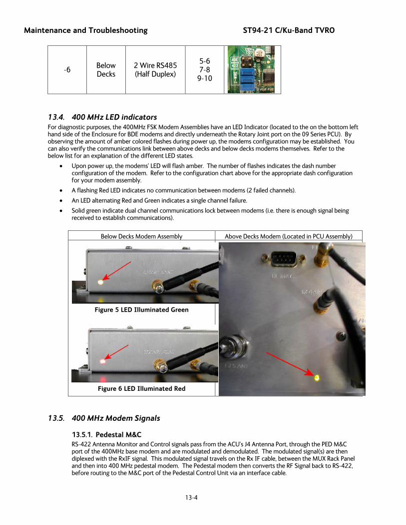
Maintenance and Troubleshooting ST94-21 C/Ku-Band TVRO
13-4
-6 Below Decks
2 Wire RS485 (Half Duplex)
5-6 7-8
9-10
13.4. 400 MHz LED indicators For diagnostic purposes, the 400MHz FSK Modem Assemblies have an LED Indicator (located to the on the bottom left hand side of the Enclosure for BDE modems and directly underneath the Rotary Joint port on the 09 Series PCU). By observing the amount of amber colored flashes during power up, the modems configuration may be established. You can also verify the communications link between above decks and below decks modems themselves. Refer to the below list for an explanation of the different LED states.
• Upon power up, the modems’ LED will flash amber. The number of flashes indicates the dash number configuration of the modem. Refer to the configuration chart above for the appropriate dash configuration for your modem assembly.
• A flashing Red LED indicates no communication between modems (2 failed channels).
• An LED alternating Red and Green indicates a single channel failure.
• Solid green indicate dual channel communications lock between modems (i.e. there is enough signal being received to establish communications).
Below Decks Modem Assembly Above Decks Modem (Located in PCU Assembly)
Figure 5 LED Illuminated Green
Figure 6 LED Illuminated Red
13.5. 400 MHz Modem Signals
13.5.1. Pedestal M&C RS-422 Antenna Monitor and Control signals pass from the ACU’s J4 Antenna Port, through the PED M&C port of the 400MHz base modem and are modulated and demodulated. The modulated signal(s) are then diplexed with the RxIF signal. This modulated signal travels on the Rx IF cable, between the MUX Rack Panel and then into 400 MHz pedestal modem. The Pedestal modem then converts the RF Signal back to RS-422, before routing to the M&C port of the Pedestal Control Unit via an interface cable.

ST94-21 C/Ku-Band TVRO Maintenance and Troubleshooting
13-5
13.5.2. Radio M&C The RS-232, RS-422, or RS-485 (depending on configuration) Radio M&C signals pass from the BDE computer through the RF M&C port of the base modem and are modulated and demodulated. These M&C signals are diplexed with the Pedestal M&C signals before passing through to the above decks modem. The Pedestal modem then converts the RF Signal back to RS-232/422/485, before routing to the M&C port of the above decks radio equipment via an interface cable.
13.5.3. Channel Identification There are four base frequencies used in the 400MHz FSK modem assemblies:
• The BDE Modem Transmits Pedestal M&C at 452.5 MHz
• The BDE Modem Transmits Radio M&C at 447.5 MHz
• The ADE Modem Transmits Pedestal M&C at 465.0 MHz
• The ADE Modem Transmits Radio M&C at 460.0 MHz
Figure 7 ADE Modem Transmit Frequency Markers
Figure 8 BDE Modem Transmit Frequency Markers
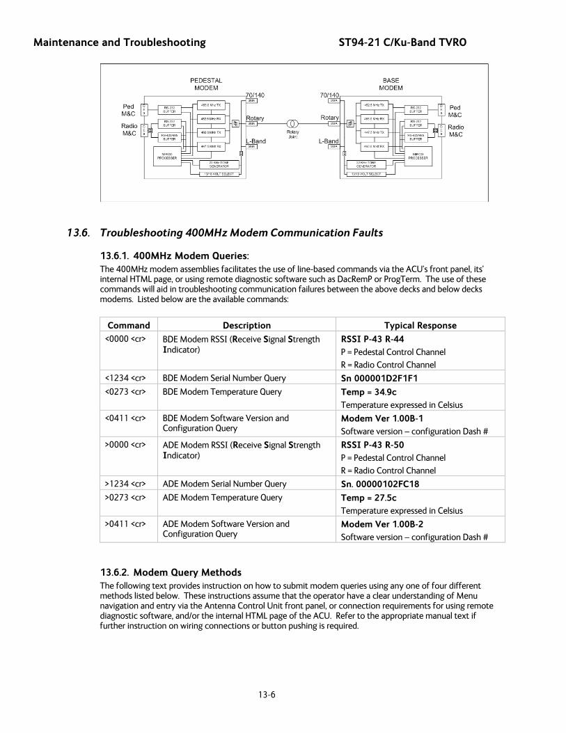
Maintenance and Troubleshooting ST94-21 C/Ku-Band TVRO
13-6
13.6. Troubleshooting 400MHz Modem Communication Faults
13.6.1. 400MHz Modem Queries: The 400MHz modem assemblies facilitates the use of line-based commands via the ACU’s front panel, its’ internal HTML page, or using remote diagnostic software such as DacRemP or ProgTerm. The use of these commands will aid in troubleshooting communication failures between the above decks and below decks modems. Listed below are the available commands:
Command Description Typical Response
<0000 <cr> BDE Modem RSSI (Receive Signal Strength Indicator)
RSSI P-43 R-44 P = Pedestal Control Channel
R = Radio Control Channel
<1234 <cr> BDE Modem Serial Number Query Sn 000001D2F1F1
<0273 <cr> BDE Modem Temperature Query Temp = 34.9c Temperature expressed in Celsius
<0411 <cr> BDE Modem Software Version and Configuration Query
Modem Ver 1.00B-1 Software version – configuration Dash #
>0000 <cr> ADE Modem RSSI (Receive Signal Strength Indicator)
RSSI P-43 R-50 P = Pedestal Control Channel
R = Radio Control Channel
>1234 <cr> ADE Modem Serial Number Query Sn. 00000102FC18
>0273 <cr> ADE Modem Temperature Query Temp = 27.5c Temperature expressed in Celsius
>0411 <cr> ADE Modem Software Version and Configuration Query
Modem Ver 1.00B-2 Software version – configuration Dash #
13.6.2. Modem Query Methods The following text provides instruction on how to submit modem queries using any one of four different methods listed below. These instructions assume that the operator have a clear understanding of Menu navigation and entry via the Antenna Control Unit front panel, or connection requirements for using remote diagnostic software, and/or the internal HTML page of the ACU. Refer to the appropriate manual text if further instruction on wiring connections or button pushing is required.

ST94-21 C/Ku-Band TVRO Maintenance and Troubleshooting
13-7
13.6.2.1. Using the ACU Front Panel
1. Using the ACU’s Front Panel, navigate through the Setup menu to access the Remote Command Sub-Menu.
2. Enter in the desired Modem Query then press the ENTER key.
3. Observe and/or Record the
displayed response.
13.6.2.2. Using the Internal HTML Page
1. Logon to the ACU’s Internal HTML page.
2. Browse to the “Communication Port Settings” page.
3. In the Command Window,
Type in the desired Modem
Query and hit Send .
4. Observe and/or Record the displayed response.
5. Repeat as required until all desired modem queries are noted.
13.6.2.3. Using DacRemP
1. Open up DacRemP and select the Comm Diagnostics Tool (cntrl + c).
2. In the Remote Command Entry
Window, type in the desired Modem Query and hit Enter. i.e “<1234 <CR>”

Maintenance and Troubleshooting ST94-21 C/Ku-Band TVRO
13-8
3. Observe and/or Record the displayed response.
4. Repeat as required until all desired modem queries are noted.
13.6.2.4. Using ProgTerm
1. Open up ProgTerm and select the Tools Menu.
2. Select “Modem Tools”.
3. Select the desired modem
location.
BDE is the Below Decks Modem.
ADE is the Above Decks Modem.
4. Select the desired modem query.
5. Observe and/or Record the
displayed response.
6. Repeat as desired until all desired modem queries are noted.
13.6.3. Isolating a 400 MHz Modem Fault Procedure: 1. Issue “<0000” and “>0000” queries to the ADE and BDE modems and record the responses.
ADE (>0000)______________ BDE (<0000)______________
2. Compare your recorded responses to the list below to determine what modem fault(s) (if any) is present.
3. Use the appropriate text following the failure table for a list of possible failures attributed to the failure type established.
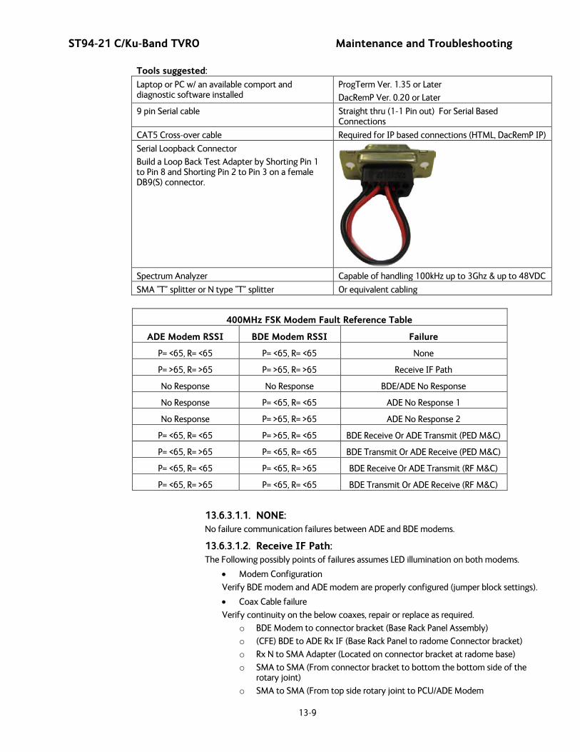
ST94-21 C/Ku-Band TVRO Maintenance and Troubleshooting
13-9
Tools suggested:
Laptop or PC w/ an available comport and diagnostic software installed
ProgTerm Ver. 1.35 or Later
DacRemP Ver. 0.20 or Later
9 pin Serial cable Straight thru (1-1 Pin out) For Serial Based Connections
CAT5 Cross-over cable Required for IP based connections (HTML, DacRemP IP)
Serial Loopback Connector
Build a Loop Back Test Adapter by Shorting Pin 1 to Pin 8 and Shorting Pin 2 to Pin 3 on a female DB9(S) connector.
Spectrum Analyzer Capable of handling 100kHz up to 3Ghz & up to 48VDC
SMA “T” splitter or N type “T” splitter Or equivalent cabling
400MHz FSK Modem Fault Reference Table
ADE Modem RSSI BDE Modem RSSI Failure
P= <65, R= <65 P= <65, R= <65 None
P= >65, R= >65 P= >65, R= >65 Receive IF Path
No Response No Response BDE/ADE No Response
No Response P= <65, R= <65 ADE No Response 1
No Response P= >65, R= >65 ADE No Response 2
P= <65, R= <65 P= >65, R= <65 BDE Receive Or ADE Transmit (PED M&C)
P= <65, R= >65 P= <65, R= <65 BDE Transmit Or ADE Receive (PED M&C)
P= <65, R= <65 P= <65, R= >65 BDE Receive Or ADE Transmit (RF M&C)
P= <65, R= >65 P= <65, R= <65 BDE Transmit Or ADE Receive (RF M&C)
13.6.3.1.1. NONE: No failure communication failures between ADE and BDE modems.
13.6.3.1.2. Receive IF Path: The Following possibly points of failures assumes LED illumination on both modems.
• Modem Configuration
Verify BDE modem and ADE modem are properly configured (jumper block settings).
• Coax Cable failure
Verify continuity on the below coaxes, repair or replace as required.
o BDE Modem to connector bracket (Base Rack Panel Assembly)
o (CFE) BDE to ADE Rx IF (Base Rack Panel to radome Connector bracket)
o Rx N to SMA Adapter (Located on connector bracket at radome base)
o SMA to SMA (From connector bracket to bottom the bottom side of the rotary joint)
o SMA to SMA (From top side rotary joint to PCU/ADE Modem
Maintenance and Troubleshooting ST94-21 C/Ku-Band TVRO
13-10
• Rotary Joint (Receive channel)
Verify continuity on the receive channel for its entire 360 degree range of motion. Replace rotary joint if any sector of it has failed.
13.6.3.1.3. BDE/ADE No Response: The Following possibly points of failures assumes LED illumination on both modems.
• Modem Configuration
Verify BDE modem and ADE modem are properly configured (jumper block settings).
• ACU to BDE modem interface cable failure
Verify harness continuity. Repair or replace as required
• ACU Antenna Port Failure
o Install an RS232 Loopback connector** on Antenna Port of the ACU. Enter an “n0999” Remote Command and verify that it echoes back on the bottom line of the display.
1. If loop back works, BDE Modem failure or ACU to BDE Interface cable failure.
2. If loop back does not work, ACU failure.
13.6.3.1.4. ADE No Response 1: (assumes LED illumination on both modems)
• Modem Configuration
Verify BDE modem and ADE modem are properly configured (jumper block settings).
o Install Spectrum Analyzer in line with the Rx IF coax path. 1. If 465.0MHz Transmit Beacon is present, the fault is the BDE
modem. 2. If 465.0MHz Transmit Beacon is NOT present fault is with the
ADE modem.
13.6.3.1.5. ADE No Response 2: • ADE Modem Configuration
Verify the ADE modem is properly configured (jumper block settings).
• Coax Cable failure
Verify continuity on the items listed below, repair or replace as required.
o Base Modem to connector bracket (Base Rack Panel Assembly)
o (CFE) BDE to ADE Rx (LMR-400)
o Rx N to SMA Adapter (Connector bracket at Radome base)
o SMA to SMA connector bracket to bottom side rotary joint
o SMA to SMA top side rotary joint to PCU/ADE Modem
• Rotary Joint (Receive channel)
Verify continuity on the receive channel for its entire 360 degree range of motion. Replace rotary joint if any sector of it has failed.
13.6.3.1.6. BDE Receive Or ADE Transmit (PED M&C): • BDE Modem Rx Port Failure (Not receiving at 465.0MHz) or
• ADE Modem Tx Port Failure (Not transmitting at 465.0MHz)
o Install Spectrum Analyzer in line with the Rx IF coax path. 1. If 465.0MHz Transmit Beacon is present, the fault is the BDE
modem. 2. If 465.0MHz Transmit Beacon is NOT present fault is with the
ADE modem.
13.6.3.1.7. BDE Transmit or ADE Receive (PED M&C): • BDE Modem Tx Port Failure (Not transmitting at 452.5MHz) or

ST94-21 C/Ku-Band TVRO Maintenance and Troubleshooting
13-11
• ADE Modem Rx Port Failure (Not receiving at 452.50MHz)
o Install Spectrum Analyzer in line with the Rx IF coax path. 1. If 452.5MHz Transmit Beacon is present, the fault is the BDE
modem. 2. If 452.5MHz Transmit Beacon is NOT present, the fault is with
the ADE modem.
13.6.3.1.8. BDE Receive or ADE Transmit (RF M&C): • BDE Modem Rx Port Failure (Not receiving at 460.0MHz) or
• ADE Modem Tx Port Failure (Not transmitting at 460.0MHz)
o Install Spectrum Analyzer in line with the Rx IF coax path. 1. If 465.0MHz Transmit Beacon in present, the fault is the BDE
modem. 2. If 465.0MHz Transmit Beacon is NOT present, the fault is with
the ADE modem.
13.6.3.1.9. BDE Transmit Or ADE Receive (Radio M&C):
• BDE Modem Tx Port Failure (Not transmitting at 447.5MHz) or
• ADE Modem Rx Port Failure (Not receiving at 447.5MHz)
o Install Spectrum Analyzer in line with the Rx IF coax path. 1. If 465.0MHz Transmit Beacon in present, the fault is the BDE
modem. 2. If 465.0MHz Transmit Beacon is NOT present, the fault is with
the ADE modem.
13.7. Troubleshooting
13.7.1. Theory Of Stabilization Operation The antenna system is mounted on a three axis stabilization assembly that provides free motion with 3 degrees of freedom. This assembly allows the inertia of the antenna system to hold the antenna pointed motionless in inertial space while the ship rolls, pitches and yaws beneath the assembly. Three low friction torque motors attached to each of the three free axes of the assembly provide the required force to overcome the disturbing torque imposed on the antenna system by cable restraints, bearing friction and small air currents within the radome. These motors are also used to re-position the antenna in azimuth and elevation.
The Pedestal Control Unit (PCU) uses inputs from the level cage sensors to calculate the amount of torque required in each axis to keep the antenna pointed within +/-0.2 degrees. The primary sensor input for each loop is the rate sensor mounted in the Level Cage Assembly. This sensor reports all motion of the antenna to the PCU. The PCU immediately responds by applying a torque in the opposite direction to the disturbance to bring the antenna back to its desired position. Both the instantaneous output of the rate sensor (Velocity Error) and the integrated output of the rate sensor (Position Error) are used to achieve the high pointing accuracy specification.
The calculated torque commands are converted to a 5 volt differential analog signal by a Digital to Analog converter (D/A) and sent to each of three Brush-Less Servo Amplifiers. These amplifiers provide the proper drive polarities and commutation required to operate the Brush-Less DC Servo Motors in torque mode. The Torque acting on the mass of the antenna cause it to move, restoring the rate sensors to their original position, and closing the control loop.
Since the rate sensors only monitor motion and not absolute position, a second input is required in each axis as a long term reference to keep the antenna from slowly drifting in position. The Level and Cross Level reference is provided by a two axis tilt sensor in the level cage assembly. The Azimuth reference is provided by combining the ships gyro compass input and the antenna relative position.
13.7.2. ST-21 Series Dual C-Band OR Quad Ku-Band TVRO RF Flow Refer to the System Block Diagram in the Drawings section of this manual. The feed has a 24VDC motor to rotate the body of the OMT to optimize the linear polarization angle of the LNBs to the polarization angle of
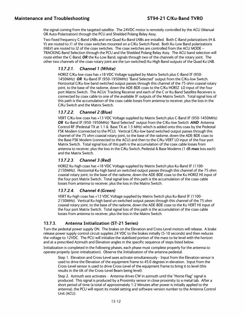
Maintenance and Troubleshooting ST94-21 C/Ku-Band TVRO
13-12
the signal coming from the targeted satellite. The 24VDC motor is remotely controlled by the ACU (Manual OR Auto-Polarization) through the PCU and Shielded Polang Relay Assy.
Two fixed frequency C-Band LNBs and one Quad Ku-Band LNBs are installed. Both C-Band polarizations (H & V) are routed to J1 of the coax switches mounted on a C/Ku Switch Panel. Both Ku-Low Band polarizations (H&V) are routed to J2 of the coax switches. The coax switches are controlled from the ACU MODE – TRACKING Band Selection through the PCU and the Shielded Polang Relay Assy. The ACU band selection will route either the C-Band, OR the Ku-Low Band, signals through two of the channels of the rotary joint. The other two channels of the coax rotary joint are the (un-switched) Ku-High Band outputs of the Quad Ku LNB.
13.7.2.1. Channel 1 (White) HORIZ C/Ku-low coax has +18 VDC Voltage supplied by Matrix Switch plus C-Band IF (950-1450MHz) OR Ku-Band IF (950-1950MHz) “Band Selected” output from the C/Ku-low Switch. Horizontal C/Ku-low band switched output passes through this channel of the 75 ohm coaxial rotary joint, to the base of the radome, down the ADE-BDE coax to the C/Ku HORIZ LO input of the four port Matrix Switch. The ACUs’ Tracking Receiver and each of the C or Ku-Band Satellite Receivers is connected by coax cable to one of the available IF outputs of the Matrix Switch. Total signal loss of this path is the accumulation of the coax cable losses from antenna to receiver, plus the loss in the C/Ku Switch and the Matrix Switch.
13.7.2.2. Channel 2 (Blue) VERT C/Ku-low coax has +13 VDC Voltage supplied by Matrix Switch plus C-Band IF (950-1450MHz) OR Ku-Band IF (950-1950MHz) “Band Selected” output from the C/Ku-low Switch AND Antenna Control RF (Pedestal TX at 1.1 & Base TX at 1.5 MHz) which is added onto this coax by the Pedestal FSK Modem (connected to the PCU). Vertical C/Ku-low band switched output passes through this channel of the 75 ohm coaxial rotary joint, to the base of the radome, down the ADE-BDE coax to the Base FSK Modem (connected to the ACU) and then to the C/Ku VERT LO input of the four port Matrix Switch. Total signal loss of this path is the accumulation of the coax cable losses from antenna to receiver, plus the loss in the C/Ku Switch, Pedestal & Base Modems (1 dB max loss each) and the Matrix Switch.
13.7.2.3. Channel 3 (Red) HORIZ Ku-high coax has +18 VDC Voltage supplied by Matrix Switch plus Ku-Band IF (1100-2150MHz). Horizontal Ku-high band un-switched output passes through this channel of the 75 ohm coaxial rotary joint, to the base of the radome, down the ADE-BDE coax to the Ku HORIZ HI input of the four port Matrix Switch. Total signal loss of this path is the accumulation of the coax cable losses from antenna to receiver, plus the loss in the Matrix Switch.
13.7.2.4. Channel 4 (Green) VERT Ku-high coax has +13 VDC Voltage supplied by Matrix Switch plus Ku-Band IF (1100-2150MHz). Vertical Ku-high band un-switched output passes through this channel of the 75 ohm coaxial rotary joint, to the base of the radome, down the ADE-BDE coax to the Ku VERT HI input of the four port Matrix Switch. Total signal loss of this path is the accumulation of the coax cable losses from antenna to receiver, plus the loss in the Matrix Switch.
13.7.3. Antenna Initialization (ST-21 Series) Turn the pedestal power supply ON. The brakes on the Elevation and Cross-Level motors will release. A brake release power supply control circuit supplies 24 VDC to the brakes initially (5-10 seconds) and then reduces the voltage to 12VDC. The PCU will initialize the stabilized portion of the mass to be level with the horizon and at a prescribed Azimuth and Elevation angles in the specific sequence of steps listed below.
Initialization is completed in the following phases, each phase must complete properly for the antenna to operate properly (post-initialization). Observe the Initialization of the antenna pedestal.
Step 1. Elevation and Cross-Level axes activate simultaneously - Input from the Elevation sensor is used to drive the Elevation of the equipment frame to 45.0 degrees in elevation. Input from the Cross-Level sensor is used to drive Cross-Level of the equipment frame to bring it to level (this results in the tilt of the Cross-Level Beam being level).
Step 2. Azimuth axis activates - Antenna drives CW in azimuth until the “Home Flag” signal is produced. This signal is produced by a Proximity sensor in close proximity to a metal tab. After a short period of time (a total of approximately 1-2 Minutes after power is initially applied to the antenna), the PCU will report its model setting and software version number to the Antenna Control Unit (ACU).
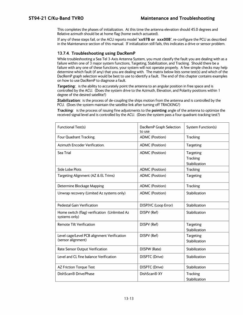
ST94-21 C/Ku-Band TVRO Maintenance and Troubleshooting
13-13
This completes the phases of initialization. At this time the antenna elevation should 45.0 degrees and Relative azimuth should be at home flag (home switch actuated).
If any of these steps fail, or the ACU reports model "xx97B or xxx00B", re-configure the PCU as described in the Maintenance section of this manual. If initialization still fails, this indicates a drive or sensor problem.
13.7.4. Troubleshooting using DacRemP While troubleshooting a Sea Tel 3-Axis Antenna System, you must classify the fault you are dealing with as a failure within one of 3 major system functions, Targeting, Stabilization, and Tracking. Should there be a failure with any one of these functions, your system will not operate properly. A few simple checks may help determine which fault (if any) that you are dealing with. The matrix below lists some test(s) and which of the DacRemP graph selection would be best to use to identify a fault. The end of this chapter contains examples on how to use DacRemP to diagnose a fault.
Targeting: is the ability to accurately point the antenna to an angular position in free space and is controlled by the ACU. (Does the system drive to the Azimuth, Elevation, and Polarity positions within 1 degree of the desired satellite?)
Stabilization: is the process of de-coupling the ships motion from the antenna and is controlled by the PCU. (Does the system maintain the satellite link after turning off TRACKING?)
Tracking: is the process of issuing fine adjustments to the pointing angle of the antenna to optimize the received signal level and is controlled by the ACU. (Does the system pass a four quadrant-tracking test?)
Functional Test(s) DacRemP Graph Selection to use
System Function(s)
Four Quadrant Tracking. ADMC (Position) Tracking
Azimuth Encoder Verification. ADMC (Position) Targeting
Sea Trial ADMC (Position) Targeting
Tracking
Stabilization
Side Lobe Plots ADMC (Position) Tracking
Targeting Alignment (AZ & EL Trims) ADMC (Position) Targeting
Determine Blockage Mapping ADMC (Position) Tracking
Unwrap recovery (Limited Az systems only) ADMC (Position) Stabilization
Pedestal Gain Verification DISPIVC (Loop Error) Stabilization
Home switch (flag) verification (Unlimited Az systems only)
DISPV (Ref) Stabilization
Remote Tilt Verification DISPV (Ref) Targeting
Stabilization
Level cage/Level PCB alignment Verification (sensor alignment)
DISPV (Ref) Targeting
Stabilization
Rate Sensor Output Verification DISPW (Rate) Stabilization
Level and CL fine balance Verification DISPTC (Drive) Stabilization
AZ Friction Torque Test DISPTC (Drive) Stabilization
DishScan® Drive/Phase DishScan® XY Tracking
Stabilization

Maintenance and Troubleshooting ST94-21 C/Ku-Band TVRO
13-14
13.7.5. Antenna Loop Error Monitoring The DacRemP DISPIVC graph chart provides a means for monitoring the accumulated velocity errors of the antenna for diagnostic purposes. If this error is excessive, it indicates external forces are acting on the antenna. These forces may be the result of but not restricted to static imbalance, excessive bearing friction, cable binding, or wind loading. If these forces cause the antenna to mis-point by more than 0.5° from the desired position the PCU will flag a “Stab Limit” error.
• To view the position error, select the graph chart.
• This chart displays sensed axis errors via three traces, CL (Cross Level), LV (Elevation), and AZ
(Azimuth), at a fixed 0.05º/ vertical division.
• The normal trace average will plots it’s display ± 3 divisions from the red reference line. Any trace line average plotted above this is of concern and troubleshooting required. The example below shows the forces exerted onto the antenna as a resultant of DishScan® Drive. The example below shows the results of various forces put upon antenna.
• Cross-Level Axis physically moved CCW (down to the left.) and then CW (up to the right.)
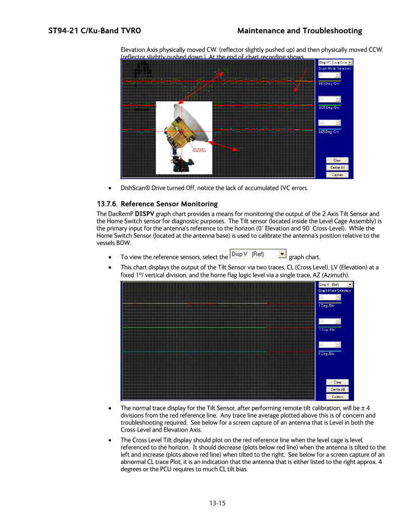
ST94-21 C/Ku-Band TVRO Maintenance and Troubleshooting
13-15
Elevation Axis physically moved CW. (reflector slightly pushed up) and then physically moved CCW. (reflector slightly pushed down.) At the end of chart recording shows
• DishScan® Drive turned Off, notice the lack of accumulated IVC errors.
13.7.6. Reference Sensor Monitoring The DacRemP DISPV graph chart provides a means for monitoring the output of the 2 Axis Tilt Sensor and the Home Switch sensor for diagnostic purposes. The Tilt sensor (located inside the Level Cage Assembly) is the primary input for the antenna’s reference to the horizon (0° Elevation and 90° Cross-Level). While the Home Switch Sensor (located at the antenna base) is used to calibrate the antenna’s position relative to the vessels BOW.
• To view the reference sensors, select the graph chart.
• This chart displays the output of the Tilt Sensor via two traces, CL (Cross Level), LV (Elevation) at a fixed 1º/ vertical division, and the home flag logic level via a single trace, AZ (Azimuth).
• The normal trace display for the Tilt Sensor, after performing remote tilt calibration, will be ± 4
divisions from the red reference line. Any trace line average plotted above this is of concern and troubleshooting required. See below for a screen capture of an antenna that is Level in both the Cross-Level and Elevation Axis.
• The Cross Level Tilt display should plot on the red reference line when the level cage is level, referenced to the horizon. It should decrease (plots below red line) when the antenna is tilted to the left and increase (plots above red line) when tilted to the right. See below for a screen capture of an abnormal CL trace Plot, it is an indication that the antenna that is either listed to the right approx. 4 degrees or the PCU requires to much CL tilt bias.

Maintenance and Troubleshooting ST94-21 C/Ku-Band TVRO
13-16
• The Level tilt display should plot on the red reference line when the level cage is level, referenced to
the horizon. It should decrease (plots below red line) when the antenna is tilted forward (EL down) and increase (plots above red line) when tilted back (EL up).
• The Azimuth display for the Home Switch will normally display a logic level high (plots directly on
Red reference line after clicking on the button) when the home flag is NOT engaged and changing to a logic level low when engaged. See below for a screen capture of an antenna that was driven so that the Home Flag switch is engaged.
13.7.7. Open Loop Rate Sensor Monitoring The DacRemP DISPW graph chart provides a means for monitoring the output of the 3 solid state rate sensors (located inside the Level Cage Assembly) for diagnostic purposes. The rate sensors are the primary inputs to the PCU for stabilization.
• To monitor the rate sensors, select the graph chart
• This chart displays sensed output from the 3 rate sensors via three traces, CL (Cross Level), LV (Elevation), and AZ (Azimuth), at a fixed 1º/Second/vertical division.
• A normal trace display will be ± 1 divisions from the red reference line. The example shown below shows an antenna that is NOT currently sensing motion in any axis.
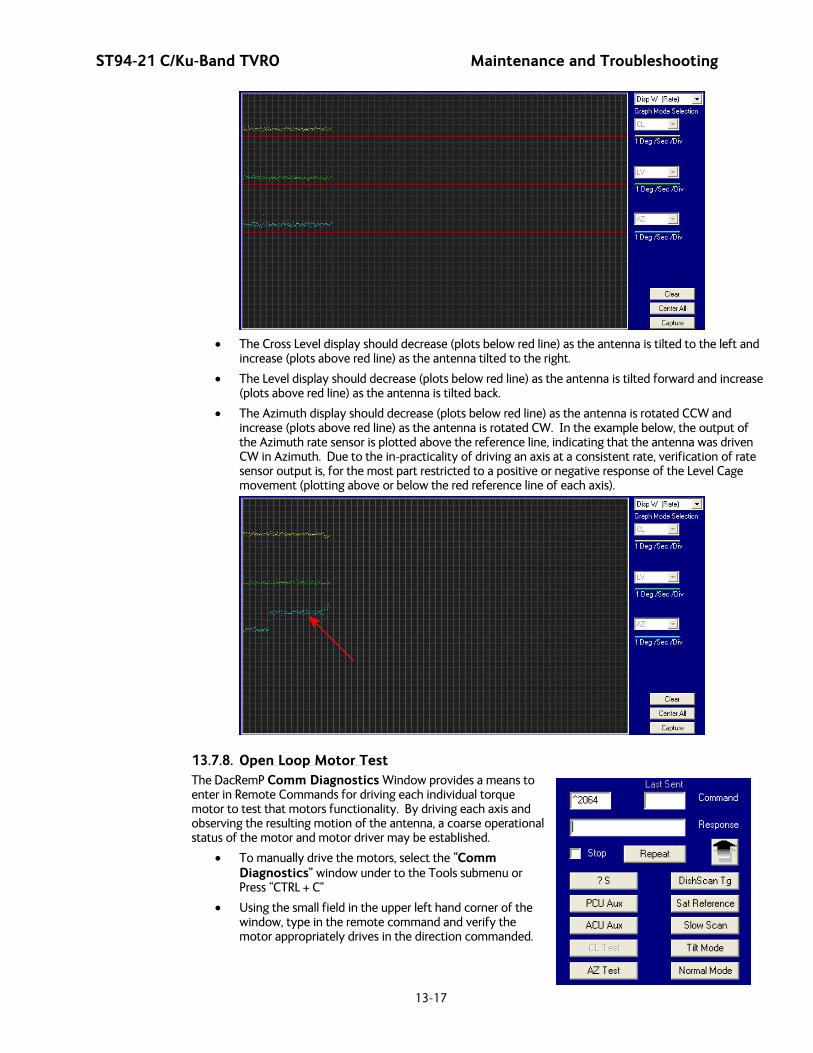
ST94-21 C/Ku-Band TVRO Maintenance and Troubleshooting
13-17
• The Cross Level display should decrease (plots below red line) as the antenna is tilted to the left and
increase (plots above red line) as the antenna tilted to the right.
• The Level display should decrease (plots below red line) as the antenna is tilted forward and increase (plots above red line) as the antenna is tilted back.
• The Azimuth display should decrease (plots below red line) as the antenna is rotated CCW and increase (plots above red line) as the antenna is rotated CW. In the example below, the output of the Azimuth rate sensor is plotted above the reference line, indicating that the antenna was driven CW in Azimuth. Due to the in-practicality of driving an axis at a consistent rate, verification of rate sensor output is, for the most part restricted to a positive or negative response of the Level Cage movement (plotting above or below the red reference line of each axis).
13.7.8. Open Loop Motor Test The DacRemP Comm Diagnostics Window provides a means to enter in Remote Commands for driving each individual torque motor to test that motors functionality. By driving each axis and observing the resulting motion of the antenna, a coarse operational status of the motor and motor driver may be established.
• To manually drive the motors, select the “Comm Diagnostics” window under to the Tools submenu or Press “CTRL + C”
• Using the small field in the upper left hand corner of the window, type in the remote command and verify the motor appropriately drives in the direction commanded.

Maintenance and Troubleshooting ST94-21 C/Ku-Band TVRO
13-18
• To drive the Cross Level motor, key in ^1064, ^1128 or ^1192 and press ENTER to drive the Cross Level axis LEFT, OFF or RIGHT respectively.
• To drive the Level motor, key in ^2064, ^2128 or ^2192 and press ENTER to drive the level axis FORWARD, OFF or BACKWARD respectively.
• To drive the Azimuth motor, key in ^3064, ^3128 or ^3192 and press ENTER to drive the azimuth axis CW, OFF or CCW.
13.7.9. To Disable/Enable DishScan® Tracking optimizes the pointing of the antenna, in very fine step increments, to maximize the level of the satellite signal being received. DishScan® is the default mode of tracking.
To toggle the ON/OFF state of DishScan®, select the remote parameter DISHSCAN. This remote parameter allows you to view, or change, the DishScan® ON/OFF status.
1. Press UP arrow and ENTER to turn DishScan® ON.
2. Press DOWN arrow and ENTER to turn DishScan® OFF.
3. If you change this remote parameter, you must save the change using REMOTE PARAMETERS.
If DishScan® is OFF and the Step Integral parameter is set to 0000, you will get a constant ERROR 0016 (DishScan® error) and you will see zeros flashing in the lower left of the Azimuth and Elevation ENTRY menu displays. This is a visual indication that DishScan® is turned OFF.
When DishScan® is turned OFF, the system will NOT be able to properly track any satellite.
13.7.10. Satellite Reference Mode The ships gyro compass input to the ACU may be accurate and stable in static conditions and yet may NOT be accurate or stable enough in some underway dynamic conditions. If there is no gyro compass or if the input is corrupt, not stable or not consistently accurate the tracking errors will become large enough to cause the antenna to be mis-pointed off satellite.
Satellite Reference Mode will uncouple the gyro reference from the azimuth rate sensor control loop. When operating in Satellite Reference Mode changes in ships gyro reading will not directly affect the azimuth control loop. The Pedestal Control Unit will stabilize the antenna based entirely on the azimuth rate sensor loop and the tracking information from DishScan®. This will keep the azimuth rate sensor position from eventually drifting away at a rate faster than the tracking loop can correct by using the tracking errors to regulate the rate sensor bias.
Satellite Reference Mode can be used as a diagnostic mode to determine if tracking errors are caused by faulty gyro inputs.
It should normally be OFF as long as you have an accurate, reliable, gyro compass input available.
It MUST be OFF when the elevation angle is greater than 75 degrees. Above 75 degrees Elevation, the ability of Sat Reference tracking to correct the Az Rate sensor bias begins to degrade, especially on a circular C system.
Satellite Reference Mode MUST be ON when:
• No Gyro Compass is available.
• The Gyro Compass input is noisy, occasionally inaccurate or occasionally unavailable.
• Frequent or constant ACU Error Code 0001 (Gyro Compass has failed).
• Using an uncompensated Flux Gate Compass.
To view, or change, the Satellite Reference Mode status, select the SAT REF remote parameter:
1. Press the UP arrow and then press the ENTER key to turn Satellite Reference Mode ON.
2. Press the DOWN arrow and then press the ENTER key to turn Satellite Reference Mode OFF.
If you change this remote parameter, you must save the change using REMOTE PARAMETERS.
13.7.11. To Read/Decode an ACU Error Code 0008 (Pedestal Function Error): An Error Code 8 as reported by the ACU is an indication that the above decks equipment has experienced an error. One of the functions available within the “Comm Diagnostics” tool window provides the means to read and decode the actual discreet Pedestal Function Error.
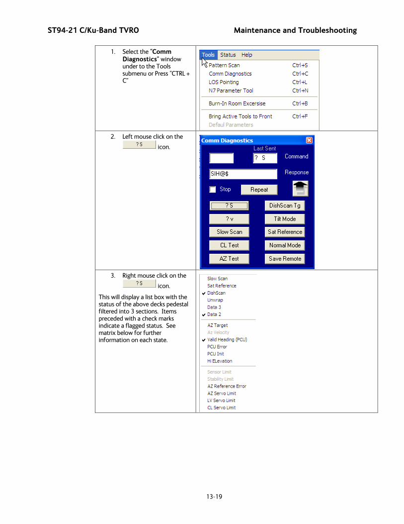
ST94-21 C/Ku-Band TVRO Maintenance and Troubleshooting
13-19
1. Select the “Comm Diagnostics” window under to the Tools submenu or Press “CTRL + C”
2. Left mouse click on the
icon.
3. Right mouse click on the
icon.
This will display a list box with the status of the above decks pedestal filtered into 3 sections. Items preceded with a check marks indicate a flagged status. See matrix below for further information on each state.

Maintenance and Troubleshooting ST94-21 C/Ku-Band TVRO
13-20
State Description
PCU Status (Word 1)
Slow Scan Indicates antenna is in a specialized mode, Slow Scan, which is required when ever a test requires driving the antenna >5°/sec
Sat Reference Indicates that satellite reference mode is enabled.
DishScan® Indicates that DishScan® Drive is enabled.
Unwrap Indicates that the antenna is currently in an “Unwrap” state.
This is not a valid error for unlimited azimuth antenna systems
Data 3 Indicates active communication between above decks and below decks equipment at the time of query
Data 2 Indicates active communication between above decks and below decks equipment at the time of query
PCU Status (Word 2)
Az Target Indicates the antenna is currently targeting a pre-determined azimuth position
Az Velocity **Not a valid state**
Valid Heading (PCU) Indicates that the PCU has received and integrated the heading value from the ACU into the Azimuth Stabilization Loop. This is NOT an indication of a proper Heading integration into ACU.
PCU Error Indicates that one or more errors have been reported by the above decks equipment.
PCU Init Indicates that the above decks equipment is currently performing an Initialization sequence
Hi Elevation Indicates that the above decks equipment is operating an Elevation Position higher than 83°
PCU Error Status (Word 3)
Sensor Limit **Not a valid state**
Stability Limit Indicates that the above decks equipment is mis-pointed from its intended target by more than 0.5°. (FCC Tx Mute Compliance)
AZ Reference Error Indicates a failure to integrate one the reference inputs within the Azimuth Stabilization Loop.
AZ Servo Limit Indicates the current draw through the Azimuth Servo Amplifier (motor driver PCB) has exceeded what is required during normal operation
LV Servo Limit Indicates the current draw through the Elevation Servo Amplifier (motor driver PCB) has exceeded what is required during normal operation
CL Servo Limit Indicates the current draw through the Cross-Level Servo Amplifier (motor driver PCB) has exceeded what is required during normal operation
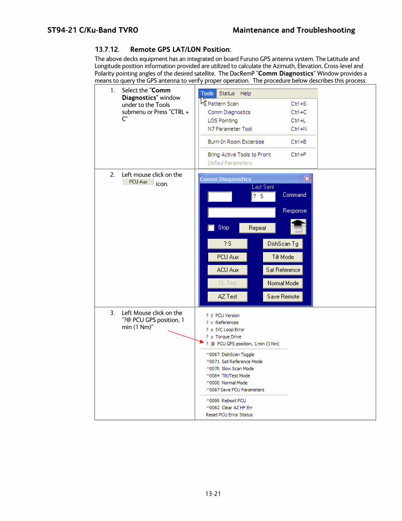
ST94-21 C/Ku-Band TVRO Maintenance and Troubleshooting
13-21
13.7.12. Remote GPS LAT/LON Position: The above decks equipment has an integrated on board Furuno GPS antenna system. The Latitude and Longitude position information provided are utilized to calculate the Azimuth, Elevation, Cross-level and Polarity pointing angles of the desired satellite. The DacRemP “Comm Diagnostics” Window provides a means to query the GPS antenna to verify proper operation. The procedure below describes this process.
1. Select the “Comm Diagnostics” window under to the Tools submenu or Press “CTRL + C”
2. Left mouse click on the
icon.
3. Left Mouse click on the
“?@ PCU GPS position, 1 min (1 Nm)”
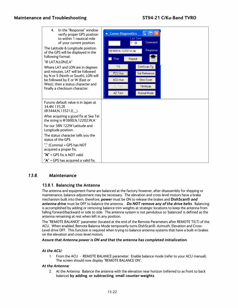
Maintenance and Troubleshooting ST94-21 C/Ku-Band TVRO
13-22
4. In the “Response” window verify proper GPS position to within 1 nautical mile of your current position.
The Latitude & Longitude position of the GPS will be displayed in the following format:
“@ LAT,N,LON,E,A”
Where LAT and LON are in degrees and minutes, LAT will be followed by N or S (North or South), LON will be followed by E or W (East or West), then a status character and finally a checksum character.
Furuno default value is in Japan at 34.4N 135.2E (@3444,N,13521,E,,_).
After acquiring a good fix at Sea Tel the string is @3800,N,12202,W,A^
for our 38N 122W Latitude and Longitude position.
The status character tells you the status of the GPS.
“,” (Comma) = GPS has NOT acquired a proper fix,
“N” = GPS fix is NOT valid
“A” = GPS has acquired a valid fix.
13.8. Maintenance
13.8.1. Balancing the Antenna The antenna and equipment frame are balanced at the factory however, after disassembly for shipping or maintenance, balance adjustment may be necessary. The elevation and cross-level motors have a brake mechanism built into them, therefore, power must be ON to release the brakes and DishScan® and antenna drive must be OFF to balance the antenna. . Do NOT remove any of the drive belts. Balancing is accomplished by adding or removing balance trim weights at strategic locations to keep the antenna from falling forward/backward or side to side. The antenna system is not pendulous so 'balanced' is defined as the antenna remaining at rest when left in any position.
The “REMOTE BALANCE” parameter (located at the end of the Remote Parameters after REMOTE TILT) of the ACU. When enabled, Remote Balance Mode temporarily turns DishScan®, Azimuth, Elevation and Cross-Level drive OFF. This function is required when trying to balance antenna systems that have a built-in brakes on the elevation and cross-level motors.
Assure that Antenna power is ON and that the antenna has completed initialization.
At the ACU: 1. From the ACU - REMOTE BALANCE parameter: Enable balance mode (refer to your ACU manual).
The screen should now display “REMOTE BALANCE ON”.
At the Antenna: 2. At the Antenna: Balance the antenna with the elevation near horizon (referred to as front to back
balance) by adding, or subtracting, small counter-weights.
ST94-21 C/Ku-Band TVRO Maintenance and Troubleshooting
13-23
3. Then balance Cross Level axis (referred to as left-right balance) by moving existing counter-weights from the left to the right or from the right to the left. Always move weight from one location on the equipment frame to the same location on the opposite side of the equipment frame (ie from the top left of the reflector mounting frame to the top right of the reflector mounting frame). Do NOT add counter-weight during this step.
4. Last, balance the antenna with the elevation pointed at, or near, zenith (referred to as top to bottom balance) by moving existing counter-weights from the top to the bottom or from the bottom to the top. Always move weight from one location on the equipment frame to the same location on the opposite side of the equipment frame (ie from the top left of the reflector mounting frame to the bottom left of the reflector mounting frame). Do NOT add counter-weight during this step.
5. When completed, the antenna will stay at any position it is pointed in for at least 5 minutes (with no ship motion).
6. Do NOT cycle antenna power to re-Initialize the antenna. Return to the ACU, which is still in REMOTE BALANCE mode, and press ENTER to exit Remote Balance Mode. When you exit Balance Mode the antenna will be re-initialized, which turns DishScan®, Azimuth, Elevation and Cross-Level drive ON.
13.8.2. To Adjust Tilt: A REMOTE TILT calibration is required to align the level cage assembly correctly so that all sensors will be aligned accurately to the axis they relate to. The fluid filled tilt sensor provides a two dimensional horizon reference. The system is not able to automatically calculate the exact center value, therefore it is necessary to perform this procedure to manually enter any offset required to make sure the PCU receives a true reference to the horizon. The procedures below describes the process of performing this calibration from either the ACU front panel or DacRemP diagnostic software by connecting the ACU’s RS-422 M&C Port to an available serial port on a Laptop/Desktop computer using a standard 9 pin serial cable.
Step 1 Turn Off DishScan Drive.
Using the DAC2202 ACU Front Panel:
3. Go to Remote Command window by pressing and holding the two LEFT & RIGHT arrows
until the EL TRIM parameter is displayed.
4. Press and release both Left & Right arrow keys again. The “SAVE NEW PARAMETERS” window should now be displayed.
5. Press either the ENTER key or the DOWN key until the “REMOTE DishScan TG” parameter is displayed.
6. Press the “RIGHT arrow to activate selection, then press the Up arrow to toggle
state to OFF. Press the ENTER key (Note: You will see that an error code 16 is generated when DishScan movement is off.)
Using DacRemP:
1. Click on the icon in the Comm Diagnostics window. (Verify that DishScan is turned off by clicking the Error LED on main display panel, there should be a check mark next to Conscan/DishScan)
(Steps 2-7 will require assistance to observe and operate antenna simultaneously)
Step 2: At Antenna, If not already installed, place a circular level bubble on top lid of level cage.
Step 3: On the ACU front Panel, press either the ENTER key or the DOWN arrow key until the REMOTE TILT window is displayed
Step 4: Push the RIGHT arrow key to activate the Remote Tilt Mode.
Step 5: Based on the feedback from the technician observing the circular bubble, the technician which operating the ACU will need to use the arrow keys to rotate the stabilized antenna mass from front to
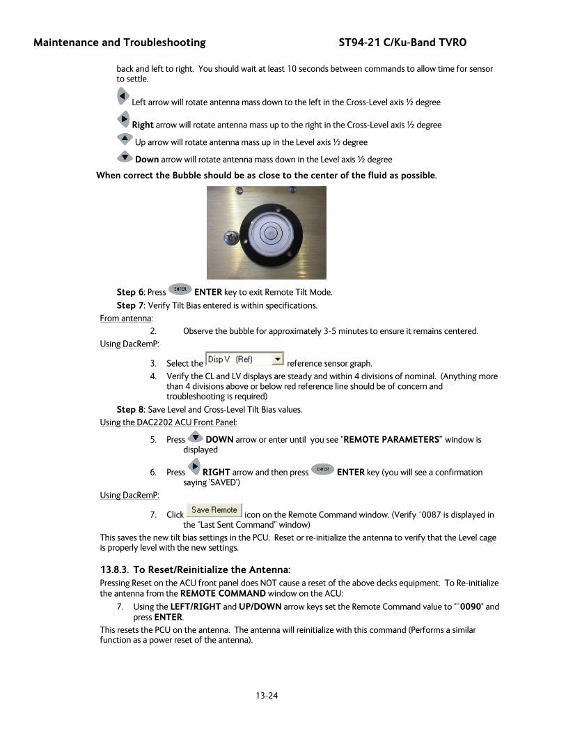
Maintenance and Troubleshooting ST94-21 C/Ku-Band TVRO
13-24
back and left to right. You should wait at least 10 seconds between commands to allow time for sensor to settle.
Left arrow will rotate antenna mass down to the left in the Cross-Level axis ½ degree
Right arrow will rotate antenna mass up to the right in the Cross-Level axis ½ degree
Up arrow will rotate antenna mass up in the Level axis ½ degree
Down arrow will rotate antenna mass down in the Level axis ½ degree
When correct the Bubble should be as close to the center of the fluid as possible.
Step 6: Press ENTER key to exit Remote Tilt Mode.
Step 7: Verify Tilt Bias entered is within specifications. From antenna:
2. Observe the bubble for approximately 3-5 minutes to ensure it remains centered.
Using DacRemP:
3. Select the reference sensor graph.
4. Verify the CL and LV displays are steady and within 4 divisions of nominal. (Anything more than 4 divisions above or below red reference line should be of concern and troubleshooting is required)
Step 8: Save Level and Cross-Level Tilt Bias values.
Using the DAC2202 ACU Front Panel:
5. Press DOWN arrow or enter until you see “REMOTE PARAMETERS” window is displayed
6. Press RIGHT arrow and then press ENTER key (you will see a confirmation saying ‘SAVED’)
Using DacRemP:
7. Click icon on the Remote Command window. (Verify ^0087 is displayed in the “Last Sent Command” window)
This saves the new tilt bias settings in the PCU. Reset or re-initialize the antenna to verify that the Level cage is properly level with the new settings.
13.8.3. To Reset/Reinitialize the Antenna: Pressing Reset on the ACU front panel does NOT cause a reset of the above decks equipment. To Re-initialize the antenna from the REMOTE COMMAND window on the ACU:
7. Using the LEFT/RIGHT and UP/DOWN arrow keys set the Remote Command value to "^0090" and press ENTER.
This resets the PCU on the antenna. The antenna will reinitialize with this command (Performs a similar function as a power reset of the antenna).
ST94-21 C/Ku-Band TVRO Maintenance and Troubleshooting
13-25
13.9. Pedestal Control Unit Configuration - STxxx-21 Series The PCU is designed to be used with a variety of antenna pedestal configurations. The configuration information that is unique to each pedestal type is stored in a Non Volatile Random Access Memory (NVRAM) in the PCU enclosure. If the PCU is replaced or the NVRAM in the PCU should become corrupt, the PCU must be re-configured to operate with the pedestal it is installed on. The default configuration for the PCU is model xx97B. In this configuration the PCU will not drive any of the three torque motors to prevent damage to the unknown pedestal.
To configure the PCU, select the REMOTE COMMAND window on the DAC-2202. Refer to the table below to key in the appropriate value for you model antenna.
13.9.1. To configure the PCU; 1. Select the REMOTE COMMAND window on the ACU.
2. Refer to the table below to key in the appropriate value for you model antenna to enter in the next step. EXAMPLE: For a ST94 Model Antenna is system type 0213.
3. Using the LEFT/RIGHT and UP/DOWN arrow keys set the Remote Command value to "N0213" and press ENTER. The display should now show "N0213".
4. Press ENTER several times to select REMOTE PARAMETERS. Press LEFT arrow and then ENTER to save the system type in the PCU.
5. Press RESET and the displayed Remote Version Number should now display "ST94 VER 2.0x".
13.9.2. MODEL CONFIGURATION NUMBERS The following table shows the current mode configuration values for ST Series pedestals with VER 2.05 or greater PCU software..
MODEL Configuration Number
Xx09 N 0000 Turns off all drive motors
ST144/14400S N 0208
ST94 N 0213
ST94 N 0212
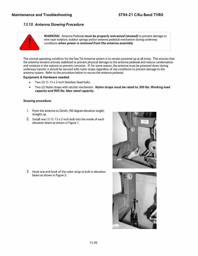
Maintenance and Troubleshooting ST94-21 C/Ku-Band TVRO
13-26
13.10. Antenna Stowing Procedure
WARNING: Antenna Pedestal must be properly restrained (stowed) to prevent damage to wire rope isolators, isolator springs and/or antenna pedestal mechanism during underway conditions when power is removed from the antenna assembly.
The normal operating condition for the Sea Tel Antenna system is to remain powered up at all times. This ensures that the antenna remains actively stabilized to prevent physical damage to the antenna pedestal and reduce condensation and moisture in the radome to prevent corrosion. If, for some reason, the antenna must be powered down during underway transits, it should be secured with nylon straps regardless of sea conditions to prevent damage to the antenna system. Refer to the procedure below to secure the antenna pedestal.
Equipment & Hardware needed:
• Two (2) ½-13 x 2-inch Stainless Steel bolts.
• Two (2) Nylon straps with ratchet mechanism. Nylon straps must be rated to 300 lbs. Working load capacity and 900 lbs. Max rated capacity.
Stowing procedure:
1. Point the antenna to Zenith, (90 degree elevation angle), straight up.
2. Install one (1) ½-13 x 2-inch bolt into the inside of each elevation beam as shown in Figure 1.
3. Hook one end hook of the nylon strap to bolt in elevation
beam as shown in Figure 2.
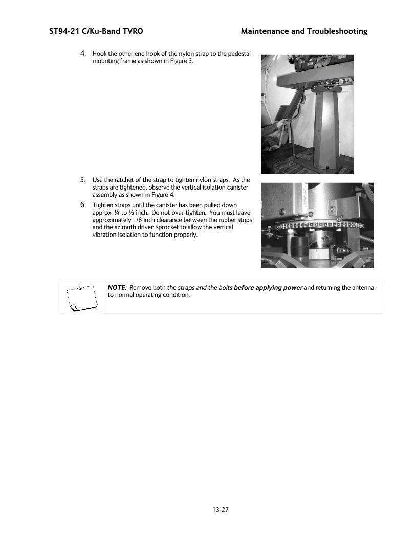
ST94-21 C/Ku-Band TVRO Maintenance and Troubleshooting
13-27
4. Hook the other end hook of the nylon strap to the pedestal-mounting frame as shown in Figure 3.
5. Use the ratchet of the strap to tighten nylon straps. As the
straps are tightened, observe the vertical isolation canister assembly as shown in Figure 4.
6. Tighten straps until the canister has been pulled down approx. ¼ to ½ inch. Do not over-tighten. You must leave approximately 1/8 inch clearance between the rubber stops and the azimuth driven sprocket to allow the vertical vibration isolation to function properly.
NOTE: Remove both the straps and the bolts before applying power and returning the antenna to normal operating condition.

Maintenance and Troubleshooting ST94-21 C/Ku-Band TVRO
13-28
This Page Intentionally Left Blank
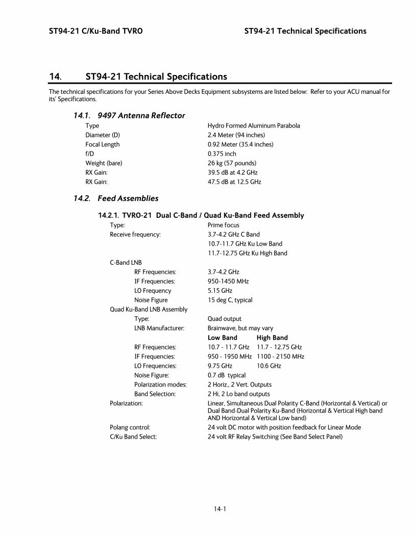
ST94-21 C/Ku-Band TVRO ST94-21 Technical Specifications
14-1
14. ST94-21 Technical Specifications
The technical specifications for your Series Above Decks Equipment subsystems are listed below: Refer to your ACU manual for its’ Specifications.
14.1. 9497 Antenna Reflector Type Hydro Formed Aluminum Parabola
Diameter (D) 2.4 Meter (94 inches)
Focal Length 0.92 Meter (35.4 inches)
f/D 0.375 inch
Weight (bare) 26 kg (57 pounds)
RX Gain: 39.5 dB at 4.2 GHz
RX Gain: 47.5 dB at 12.5 GHz
14.2. Feed Assemblies
14.2.1. TVRO-21 Dual C-Band / Quad Ku-Band Feed Assembly Type: Prime focus
Receive frequency: 3.7-4.2 GHz C Band
10.7-11.7 GHz Ku Low Band
11.7-12.75 GHz Ku High Band
C-Band LNB
RF Frequencies: 3.7-4.2 GHz
IF Frequencies: 950-1450 MHz
LO Frequency 5.15 GHz
Noise Figure 15 deg C, typical
Quad Ku-Band LNB Assembly
Type: Quad output
LNB Manufacturer: Brainwave, but may vary
Low Band High Band
RF Frequencies: 10.7 - 11.7 GHz 11.7 - 12.75 GHz
IF Frequencies: 950 - 1950 MHz 1100 - 2150 MHz
LO Frequencies: 9.75 GHz 10.6 GHz
Noise Figure: 0.7 dB typical
Polarization modes: 2 Horiz., 2 Vert. Outputs
Band Selection: 2 Hi, 2 Lo band outputs
Polarization: Linear, Simultaneous Dual Polarity C-Band (Horizontal & Vertical) or Dual Band-Dual Polarity Ku-Band (Horizontal & Vertical High band AND Horizontal & Vertical Low band)
Polang control: 24 volt DC motor with position feedback for Linear Mode
C/Ku Band Select: 24 volt RF Relay Switching (See Band Select Panel)
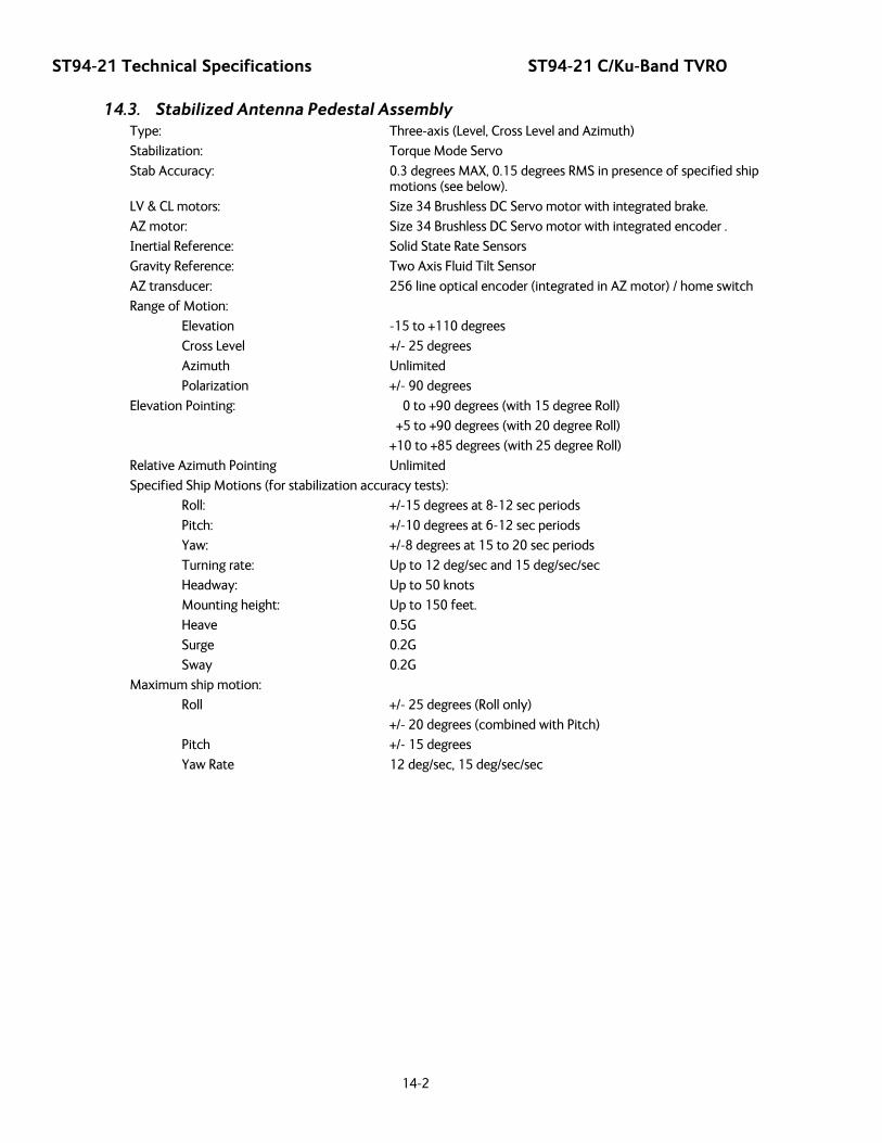
ST94-21 Technical Specifications ST94-21 C/Ku-Band TVRO
14-2
14.3. Stabilized Antenna Pedestal Assembly Type: Three-axis (Level, Cross Level and Azimuth)
Stabilization: Torque Mode Servo
Stab Accuracy: 0.3 degrees MAX, 0.15 degrees RMS in presence of specified ship motions (see below).
LV & CL motors: Size 34 Brushless DC Servo motor with integrated brake.
AZ motor: Size 34 Brushless DC Servo motor with integrated encoder .
Inertial Reference: Solid State Rate Sensors
Gravity Reference: Two Axis Fluid Tilt Sensor
AZ transducer: 256 line optical encoder (integrated in AZ motor) / home switch
Range of Motion:
Elevation -15 to +110 degrees
Cross Level +/- 25 degrees
Azimuth Unlimited
Polarization +/- 90 degrees
Elevation Pointing: 0 to +90 degrees (with 15 degree Roll)
+5 to +90 degrees (with 20 degree Roll)
+10 to +85 degrees (with 25 degree Roll)
Relative Azimuth Pointing Unlimited
Specified Ship Motions (for stabilization accuracy tests):
Roll: +/-15 degrees at 8-12 sec periods
Pitch: +/-10 degrees at 6-12 sec periods
Yaw: +/-8 degrees at 15 to 20 sec periods
Turning rate: Up to 12 deg/sec and 15 deg/sec/sec
Headway: Up to 50 knots
Mounting height: Up to 150 feet.
Heave 0.5G
Surge 0.2G
Sway 0.2G
Maximum ship motion:
Roll +/- 25 degrees (Roll only)
+/- 20 degrees (combined with Pitch)
Pitch +/- 15 degrees
Yaw Rate 12 deg/sec, 15 deg/sec/sec
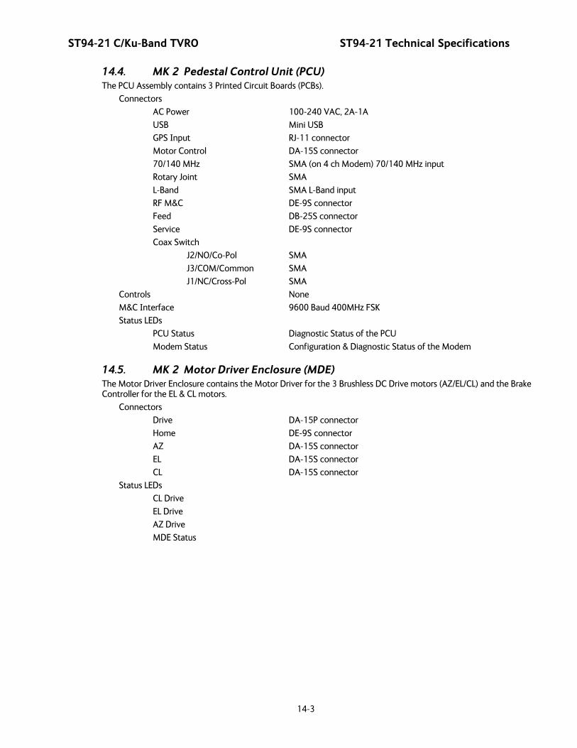
ST94-21 C/Ku-Band TVRO ST94-21 Technical Specifications
14-3
14.4. MK 2 Pedestal Control Unit (PCU) The PCU Assembly contains 3 Printed Circuit Boards (PCBs).
Connectors
AC Power 100-240 VAC, 2A-1A
USB Mini USB
GPS Input RJ-11 connector
Motor Control DA-15S connector
70/140 MHz SMA (on 4 ch Modem) 70/140 MHz input
Rotary Joint SMA
L-Band SMA L-Band input
RF M&C DE-9S connector
Feed DB-25S connector
Service DE-9S connector
Coax Switch
J2/NO/Co-Pol SMA
J3/COM/Common SMA
J1/NC/Cross-Pol SMA
Controls None
M&C Interface 9600 Baud 400MHz FSK
Status LEDs
PCU Status Diagnostic Status of the PCU
Modem Status Configuration & Diagnostic Status of the Modem
14.5. MK 2 Motor Driver Enclosure (MDE) The Motor Driver Enclosure contains the Motor Driver for the 3 Brushless DC Drive motors (AZ/EL/CL) and the Brake Controller for the EL & CL motors.
Connectors
Drive DA-15P connector
Home DE-9S connector
AZ DA-15S connector
EL DA-15S connector
CL DA-15S connector
Status LEDs
CL Drive
EL Drive
AZ Drive
MDE Status
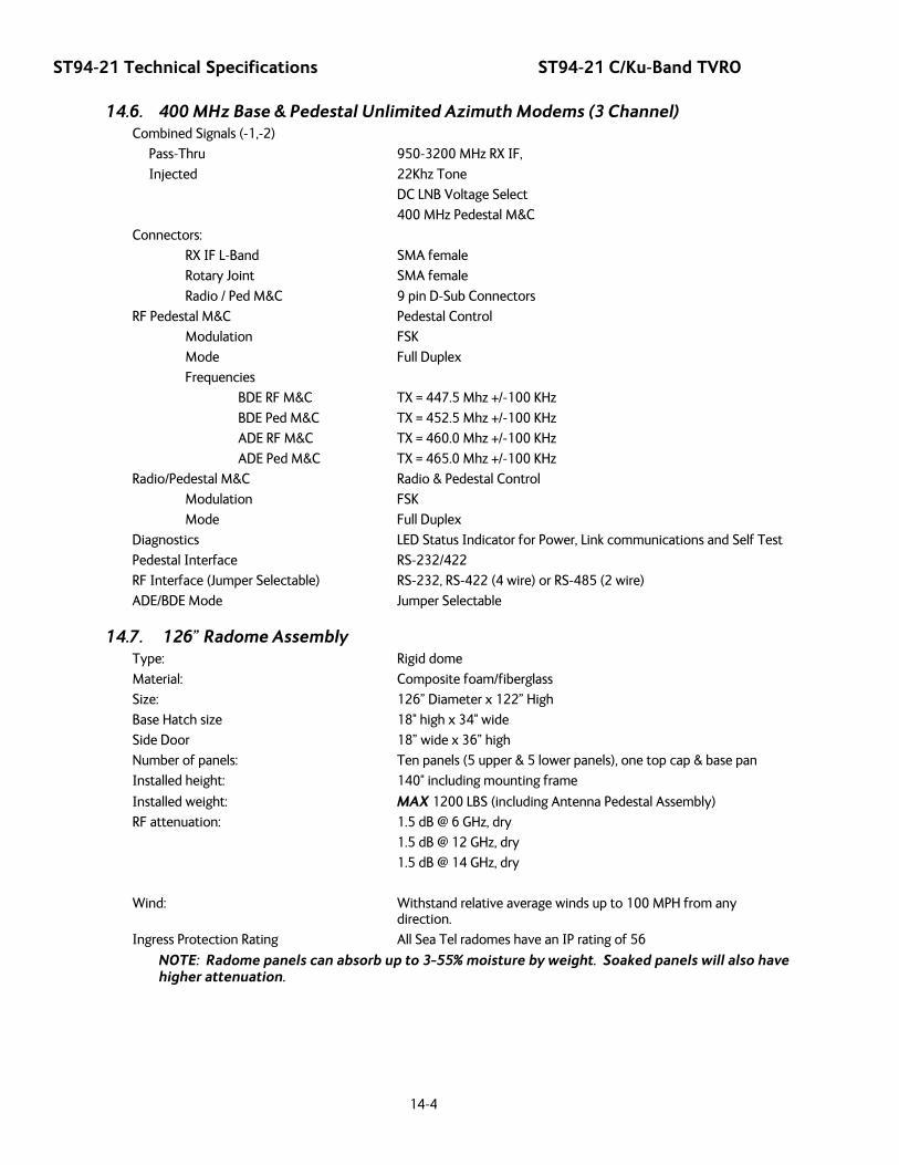
ST94-21 Technical Specifications ST94-21 C/Ku-Band TVRO
14-4
14.6. 400 MHz Base & Pedestal Unlimited Azimuth Modems (3 Channel) Combined Signals (-1,-2)
Pass-Thru 950-3200 MHz RX IF,
Injected 22Khz Tone
DC LNB Voltage Select
400 MHz Pedestal M&C
Connectors:
RX IF L-Band SMA female
Rotary Joint SMA female
Radio / Ped M&C 9 pin D-Sub Connectors
RF Pedestal M&C Pedestal Control
Modulation FSK
Mode Full Duplex
Frequencies
BDE RF M&C TX = 447.5 Mhz +/-100 KHz
BDE Ped M&C TX = 452.5 Mhz +/-100 KHz
ADE RF M&C TX = 460.0 Mhz +/-100 KHz
ADE Ped M&C TX = 465.0 Mhz +/-100 KHz
Radio/Pedestal M&C Radio & Pedestal Control
Modulation FSK
Mode Full Duplex
Diagnostics LED Status Indicator for Power, Link communications and Self Test
Pedestal Interface RS-232/422
RF Interface (Jumper Selectable) RS-232, RS-422 (4 wire) or RS-485 (2 wire)
ADE/BDE Mode Jumper Selectable
14.7. 126” Radome Assembly Type: Rigid dome
Material: Composite foam/fiberglass
Size: 126” Diameter x 122” High
Base Hatch size 18" high x 34" wide
Side Door 18” wide x 36” high
Number of panels: Ten panels (5 upper & 5 lower panels), one top cap & base pan
Installed height: 140" including mounting frame
Installed weight: MAX 1200 LBS (including Antenna Pedestal Assembly)
RF attenuation: 1.5 dB @ 6 GHz, dry
1.5 dB @ 12 GHz, dry
1.5 dB @ 14 GHz, dry
Wind: Withstand relative average winds up to 100 MPH from any direction.
Ingress Protection Rating All Sea Tel radomes have an IP rating of 56
NOTE: Radome panels can absorb up to 3-55% moisture by weight. Soaked panels will also have higher attenuation.
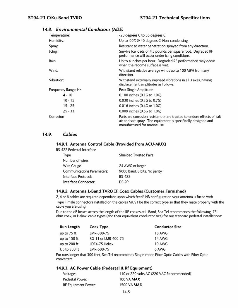
ST94-21 C/Ku-Band TVRO ST94-21 Technical Specifications
14-5
14.8. Environmental Conditions (ADE) Temperature: -20 degrees C to 55 degrees C.
Humidity: Up to l00% @ 40 degrees C, Non-condensing.
Spray: Resistant to water penetration sprayed from any direction.
Icing: Survive ice loads of 4.5 pounds per square foot. Degraded RF performance will occur under icing conditions.
Rain: Up to 4 inches per hour. Degraded RF performance may occur when the radome surface is wet.
Wind: Withstand relative average winds up to 100 MPH from any direction.
Vibration: Withstand externally imposed vibrations in all 3 axes, having displacement amplitudes as follows:
Frequency Range, Hz Peak Single Amplitude
4 - 10 0.100 inches (0.1G to 1.0G)
10 - 15 0.030 inches (0.3G to 0.7G)
15 - 25 0.016 inches (0.4G to 1.0G)
25 - 33 0.009 inches (0.6G to 1.0G)
Corrosion Parts are corrosion resistant or are treated to endure effects of salt air and salt spray. The equipment is specifically designed and manufactured for marine use.
14.9. Cables
14.9.1. Antenna Control Cable (Provided from ACU-MUX) RS-422 Pedestal Interface
Type Shielded Twisted Pairs
Number of wires
Wire Gauge 24 AWG or larger
Communications Parameters: 9600 Baud, 8 bits, No parity
Interface Protocol: RS-422
Interface Connector: DE-9P
14.9.2. Antenna L-Band TVRO IF Coax Cables (Customer Furnished) 2, 4 or 6 cables are required dependant upon which feed/LNB configuration your antenna is fitted with.
Type F male connectors installed on the cables MUST be the correct type so that they mate properly with the cable you are using.
Due to the dB losses across the length of the RF coaxes at L-Band, Sea Tel recommends the following 75 ohm coax, or Heliax, cable types (and their equivalent conductor size) for our standard pedestal installations:
Run Length Coax Type Conductor Size
up to 75 ft LMR-300-75 18 AWG
up to 150 ft RG-11 or LMR-400-75 14 AWG
up to 200 ft LDF4-75 Heliax 10 AWG
Up to 300 ft LMR-600-75 6 AWG
For runs longer that 300 feet, Sea Tel recommends Single-mode Fiber Optic Cables with Fiber Optic converters.
14.9.3. AC Power Cable (Pedestal & Rf Equipment) Voltage: 110 or 220 volts AC (220 VAC Recommended)
Pedestal Power: 100 VA MAX
RF Equipment Power: 1500 VA MAX

ST94-21 Technical Specifications ST94-21 C/Ku-Band TVRO
14-6
14.9.4. Gyro Compass Interface Cable (Customer Furnished) Type: Multi-conductor, Shielded
Number of wires 4 Conductors for Step-By-Step Gyro, 5 Conductors for Synchro
Wire Gauge: see Multi-conductor Cables spec above
Insulation: 600 VAC
14.9.5. Fiber Optic Transmitter (CFE Optional) Model: Ortel Model 3112A
Frequency Range: 950-2050 MHz
Noise Figure: 45 dB
Impedance: 75 ohm
Connectors:
RF Type F
Fiber FC/APC "Tight Fit”
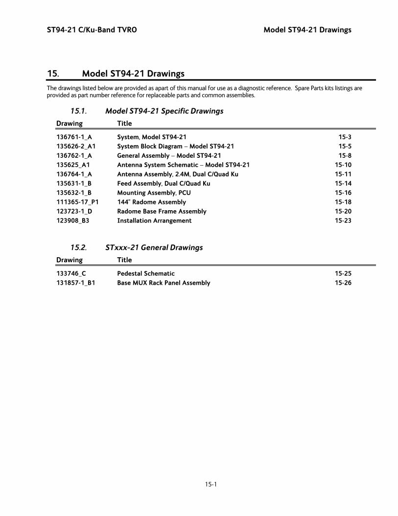
ST94-21 C/Ku-Band TVRO Model ST94-21 Drawings
15-1
15. Model ST94-21 Drawings
The drawings listed below are provided as apart of this manual for use as a diagnostic reference. Spare Parts kits listings are provided as part number reference for replaceable parts and common assemblies.
15.1. Model ST94-21 Specific Drawings
Drawing Title
136761-1_A System, Model ST94-21 15-3 135626-2_A1 System Block Diagram – Model ST94-21 15-5 136762-1_A General Assembly – Model ST94-21 15-8 135625_A1 Antenna System Schematic – Model ST94-21 15-10 136764-1_A Antenna Assembly, 2.4M, Dual C/Quad Ku 15-11 135631-1_B Feed Assembly, Dual C/Quad Ku 15-14 135632-1_B Mounting Assembly, PCU 15-16 111365-17_P1 144” Radome Assembly 15-18 123723-1_D Radome Base Frame Assembly 15-20 123908_B3 Installation Arrangement 15-23
15.2. STxxx-21 General Drawings
Drawing Title
133746_C Pedestal Schematic 15-25 131857-1_B1 Base MUX Rack Panel Assembly 15-26

Model ST94-21 Drawings ST94-21 C/Ku-Band TVRO
15-2
This Page Intentionally Left Blank

SINGLE LEVEL MFG BILL OF MATERIAL
FIND QTY PART NO REV DESCRIPTION REFERENCE DESIGNATOR
1 1 EA 136762-1 A GENERAL ASS'Y, ST94-21
2 1 EA 111365-17 P1 RADOME ASS'Y, 144 INCH, WHITE/SIDE AC
3 1 EA 123723-1 D RADOME BASE ASS'Y, 75 IN., STL, NO AC
5 1 EA 125411-2 M1 DAC-2202, DVB RCVR, 9 WIRE IF PL C3 B1 SN DAC&BDE_BoxPedestal_Crate
5 1 EA 125411-2 M1 DAC-2202, DVB RCVR, 9 WIRE IF (NOT SHOWN)
6 1 EA 131856-1 A BELOW DECK KIT, 4CH, TVRO, 400MHZ PL C3 B1 DAC&BDE_BoxPedestal_Crate
6 1 EA 131856-1 A BELOW DECK KIT, 4CH, TVRO, 400MHZ (NOT SHOWN)
11 1 EA 136767-1 A CUSTOMER DOC PACKET, STXX-21 PL C3 B1 DAC&BDE_BoxPedestal_Crate
11 1 EA 136767-1 A CUSTOMER DOC PACKET, STXX-21 (NOT SHOWN)
12 1 EA 122539-1 B SHIP STOWAGE KIT, XX97 (NOT SHOWN)
13 1 EA 114569 E BALANCE WEIGHT KIT PL C3 B2Balance_Weight_BoxPedestal_Crate
13 1 EA 114569 E BALANCE WEIGHT KIT (NOT SHOWN)
14 1 EA 124877-1 C DECAL KIT, XX97, SEATEL (126 IN/144 I (NOT SHOWN)
1SHT 1 OF
SYSTEM, ST94-21 PROD FAMILY
97 TVRO EFF. DATE4/11/2012
DRAWINGNUMBER136761-1
REV A

Written Approval From Sea Tel.
Sea Tel - Strictly Confidential & Proprietary.Do Not Copy, Distribute or Disclose Without Prior
Copyright c Sea Tel, Inc 2011 - Unpublished Work
UNLESS OTHERWISE SPECIFIEDDIMENSIONS ARE IN INCHES.
.5
X.X = .050X.XX = .020
X.XXX = .005ANGLES:
INTERPRET TOLERANCING PER ASME Y14.5 - 2009
LIFTING AND MOUNTING CUSTOMER SHALL FOLLOW
NOTES: UNLESS OTHERWISE SPECIFIED1. MANUFACTURE PER SEATEL STANDARD 122298.2. RECORDED WEIGHTS ARE THE ACTUAL MEASURED
WEIGHTS OF SYSTEM AS ORDERED. FOR SYSTEM
LOCAL SAFETY CODES
K.D.H.RELEASED TO PRODUCTION, WAS X14-5-129496A
BY
1 OF 1
WEIGHT:
JWM
D
C
B
AA
B
C
D
12345678
8 7 6 5 4
N/A
3 2 1
PROJECTION
FINISH:
MATERIAL:
DRAWN BY:
APPROVED BY: TITLE:
FIRST USED:
SIZE SCALE:
SHEET NUMBER
N/A
DRAWING NUMBER REV
B
K.D.H.
3-1-12
1:18 AST94-21
136761
DRAWN DATE:
APPROVED DATE:
SYSTEM, ST94-21
REVISION HISTORYREV ECO# DATE
SURFACE ROUGHNESS:
DESCRIPTION
Tel. 925-798-7979 Fax. 925-798-7986
3rd ANGLE
DESIGNER/ENGINEER:
SYSTEM WEIGHTS 2
DASH GA RADOME BASE FRAME AC KIT SYSTEM TOTAL-1 480 550 368 N/A 1398
REFERENCE DRAWINGS;135625 ANTENNA SYSTEM SCHEMATIC135626 SYSTEM BLOCK DIAGRAM133746 PEDESTAL SCHEMATIC123908 INSTALLATION ARRANGEMENT124877 DECAL KIT, XX97121910 SHIPYARD SPEC
3
2
1
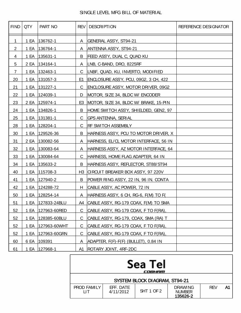
SINGLE LEVEL MFG BILL OF MATERIAL
FIND QTY PART NO REV DESCRIPTION REFERENCE DESIGNATOR
1 1 EA 136762-1 A GENERAL ASS'Y, ST94-21
2 1 EA 136764-1 A ANTENNA ASS'Y, ST94-21
4 1 EA 135631-1 B FEED ASS'Y, DUAL C, QUAD KU
5 2 EA 134164-1 A LNB, C-BAND, DRO, 8225RF
7 1 EA 132463-1 C LNBF, QUAD, KU, INVERTO, MODIFIED
20 1 EA 131057-3 E1 ENCLOSURE ASS'Y, PCU, 09G2, 3 CH, 422
21 1 EA 131227-1 C ENCLOSURE ASS'Y, MOTOR DRIVER, 09G2
22 1 EA 124039-1 D MOTOR, SIZE 34, BLDC W/ ENCODER
23 2 EA 125974-1 E3 MOTOR, SIZE 34, BLDC W/ BRAKE, 15-PIN
24 1 EA 134826-1 B HOME SWITCH ASS'Y, SHIELDED, GEN2, 97
25 1 EA 131381-1 C GPS ANTENNA, SERIAL
28 1 EA 128204-1 C RF SWITCH ASSEMBLY
30 1 EA 129526-36 B HARNESS ASS'Y, PCU TO MOTOR DRIVER, X
31 2 EA 130082-56 A HARNESS, EL/CL MOTOR INTERFACE, 56 IN
32 1 EA 130083-64 A HARNESS ASS'Y, AZ MOTOR INTERFACE, 64
33 1 EA 130084-64 C HARNESS, HOME FLAG ADAPTER, 64 IN
34 1 EA 135633-2 B HARNESS ASS'Y, REFLECTOR, ST88/ST94
40 1 EA 115708-3 H3 CIRCUIT BREAKER BOX ASS'Y, 97 220V
41 1 EA 127940-2 B POWER RING ASS'Y, 22 IN, 96 IN. CONTA
42 1 EA 124288-72 H CABLE ASS'Y, AC POWER, 72 IN
50 1 EA 128254-14 A HARNESS ASS'Y, 6 CH, RG-6, F(M) TO F(
51 1 EA 127833-24BLU A4 CABLE ASS'Y, RG-179 COAX, F(M) TO SMA
52 1 EA 127963-60RED C CABLE ASS'Y, RG-179 COAX, F TO F(RA),
52 1 EA 128385-60BLU C CABLE ASS'Y, RG-179, COAX, SMA (RA) T
52 1 EA 127963-60WHT C CABLE ASS'Y, RG-179 COAX, F TO F(RA),
52 1 EA 127963-60GRN C CABLE ASS'Y, RG-179 COAX, F TO F(RA),
60 6 EA 109391 A ADAPTER, F(F)-F(F) (BULLET), 0.84 IN
61 1 EA 127968-1 A1 ROTARY JOINT, 4RF-2DC
2SHT 1 OF
SYSTEM BLOCK DIAGRAM, ST94-21 PROD FAMILY
LIT EFF. DATE4/11/2012
DRAWINGNUMBER135626-2
REV A1

SINGLE LEVEL MFG BILL OF MATERIAL
FIND QTY PART NO REV DESCRIPTION REFERENCE DESIGNATOR
100 1 EA 125411-2 M1 DAC-2202, DVB RCVR, 9 WIRE IF
101 1 EA 131856-1 A BELOW DECK KIT, 4CH, TVRO, 400MHZ
102 1 EA 131857-1 B1 BASE MODEM RACK PANEL ASS'Y, 4CH TVRO
103 1 EA 116676 D ASSEMBLY, TERMINAL MOUNTING STRIP
105 1 EA 130854-2 F MODEM ASS'Y, 400MHZ FSK, 4CH,BDE, RS
110 1 EA 128001-8BLU A2 CABLE ASS'Y, RG-179 COAX, F(M) TO SMA
111 1 EA 128385-12BLU C CABLE ASS'Y, RG-179, COAX, SMA (RA) T
112 1 EA 128253-6 A HARNESS ASS'Y, 4 CH, RG-59, F(M) TO F
113 1 EA 111115-6 B1 CABLE ASS'Y, F(M)-F(M), 6 FT.
120 5 EA 114178 O ADAPTER, F(F)-F(F) (BULLET), 1.10 IN
130 1 EA 116298-1 G INTERFACE HARNESS ASS'Y, SINGLE MODEM
131 1 EA 120643-25 B CABLE ASS'Y, RS232, 9-WIRE, STRAIGHT,
132 1 EA 119479-10 B1 CABLE ASS'Y, CAT5 JUMPER, 10 FT.
2SHT 2 OF
SYSTEM BLOCK DIAGRAM, ST94-21 PROD FAMILY
LIT EFF. DATE4/11/2012
DRAWINGNUMBER135626-2
REV A1
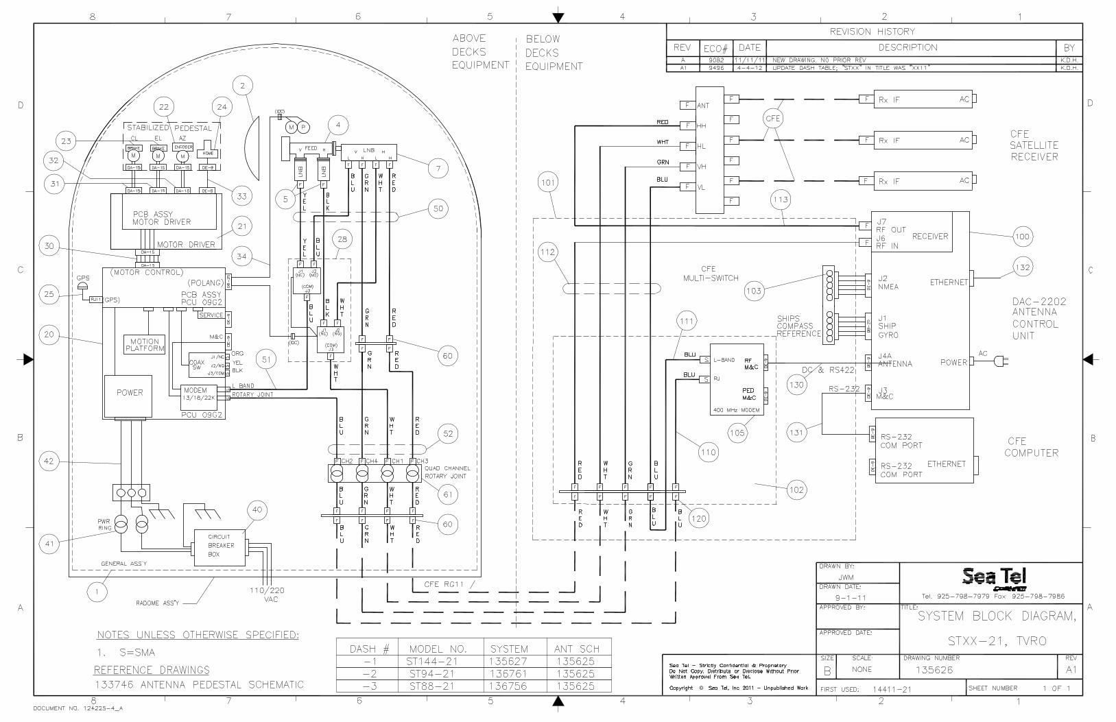
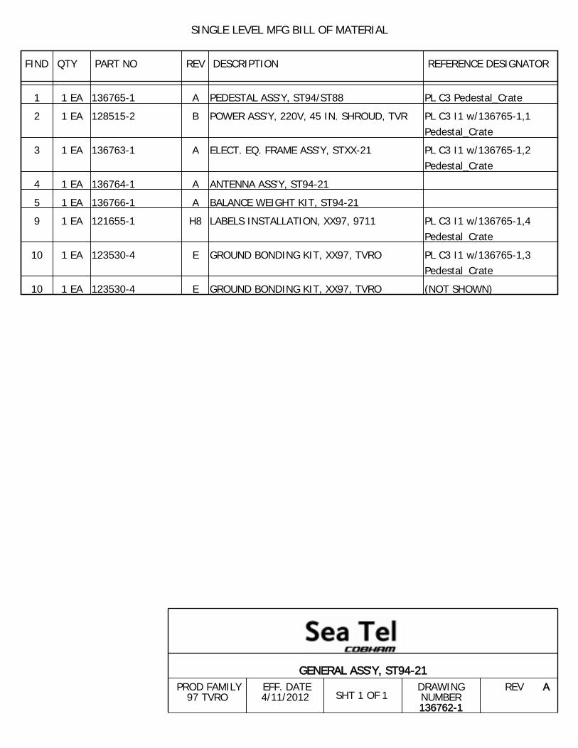
SINGLE LEVEL MFG BILL OF MATERIAL
FIND QTY PART NO REV DESCRIPTION REFERENCE DESIGNATOR
1 1 EA 136765-1 A PEDESTAL ASS'Y, ST94/ST88 PL C3 Pedestal_Crate
2 1 EA 128515-2 B POWER ASS'Y, 220V, 45 IN. SHROUD, TVR PL C3 I1 w/136765-1,1Pedestal_Crate
3 1 EA 136763-1 A ELECT. EQ. FRAME ASS'Y, STXX-21 PL C3 I1 w/136765-1,2Pedestal_Crate
4 1 EA 136764-1 A ANTENNA ASS'Y, ST94-21
5 1 EA 136766-1 A BALANCE WEIGHT KIT, ST94-21
9 1 EA 121655-1 H8 LABELS INSTALLATION, XX97, 9711 PL C3 I1 w/136765-1,4Pedestal_Crate
10 1 EA 123530-4 E GROUND BONDING KIT, XX97, TVRO PL C3 I1 w/136765-1,3Pedestal_Crate
10 1 EA 123530-4 E GROUND BONDING KIT, XX97, TVRO (NOT SHOWN)
1SHT 1 OF
GENERAL ASS'Y, ST94-21 PROD FAMILY
97 TVRO EFF. DATE4/11/2012
DRAWINGNUMBER136762-1
REV A
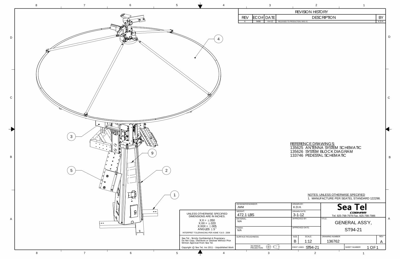
Written Approval From Sea Tel.
Sea Tel - Strictly Confidential & Proprietary.Do Not Copy, Distribute or Disclose Without Prior
Copyright c Sea Tel, Inc 2011 - Unpublished Work
UNLESS OTHERWISE SPECIFIEDDIMENSIONS ARE IN INCHES.
.5
X.X = .050X.XX = .020
X.XXX = .005ANGLES:
INTERPRET TOLERANCING PER ASME Y14.5 - 2009
1.NOTES: UNLESS OTHERWISE SPECIFIED
MANUFACTURE PER SEATEL STANDARD 122298.
K.D.H.RELEASED TO PRODUCTION, WAS X14-4-129496A
REFERENCE DRAWINGS;135625 ANTENNA SYSTEM SCHEMATIC135626 SYSTEM BLOCK DIAGRAM133746 PEDESTAL SCHEMATIC
N/A
SURFACE ROUGHNESS:
WEIGHT:
JWM
D
C
B
AA
B
C
D
12345678
8 7 6 5 4
N/A
3 2 1
PROJECTION
FINISH:
MATERIAL:
DRAWN BY:
APPROVED BY: TITLE:
FIRST USED:
SIZE SCALE:
SHEET NUMBER
472.1 LBS
DRAWING NUMBER REV
B
K.D.H.
3-1-12
1:12 AST94-21
136762
DRAWN DATE:
APPROVED DATE:
GENERAL ASS'Y,
REVISION HISTORYREV ECO# BYDESCRIPTION
ST94-21
1 OF 1
Tel. 925-798-7979 Fax. 925-798-7986
DATE
3rd ANGLE
DESIGNER/ENGINEER:
3
1
4
9
25
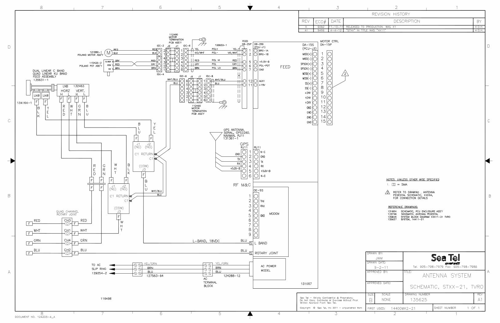
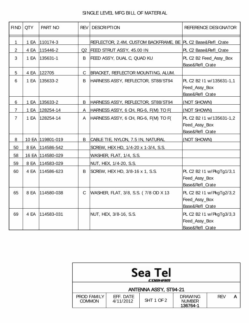
SINGLE LEVEL MFG BILL OF MATERIAL
FIND QTY PART NO REV DESCRIPTION REFERENCE DESIGNATOR
1 1 EA 110174-3 REFLECTOR, 2.4M, CUSTOM BACKFRAME, BE PL C2 Base&Refl_Crate
2 4 EA 115446-2 Q2 FEED STRUT ASS'Y, 45.00 IN PL C2 Base&Refl_Crate
3 1 EA 135631-1 B FEED ASS'Y, DUAL C, QUAD KU PL C2 B2 Feed_Assy_BoxBase&Refl_Crate
5 4 EA 122705 C BRACKET, REFLECTOR MOUNTING, ALUM.
6 1 EA 135633-2 B HARNESS ASS'Y, REFLECTOR, ST88/ST94 PL C2 B2 I1 w/135631-1,1Feed_Assy_BoxBase&Refl_Crate
6 1 EA 135633-2 B HARNESS ASS'Y, REFLECTOR, ST88/ST94 (NOT SHOWN)
7 1 EA 128254-14 A HARNESS ASS'Y, 6 CH, RG-6, F(M) TO F( (NOT SHOWN)
7 1 EA 128254-14 A HARNESS ASS'Y, 6 CH, RG-6, F(M) TO F( PL C2 B2 I1 w/135631-1,2Feed_Assy_BoxBase&Refl_Crate
8 10 EA 119801-019 B CABLE TIE, NYLON, 7.5 IN, NATURAL (NOT SHOWN)
50 8 EA 114586-542 SCREW, HEX HD, 1/4-20 x 1-3/4, S.S.
58 16 EA 114580-029 WASHER, FLAT, 1/4, S.S.
59 8 EA 114583-029 NUT, HEX, 1/4-20, S.S.
60 4 EA 114586-623 B SCREW, HEX HD, 3/8-16 x 1, S.S. PL C2 B2 I1 w/PkgTg1/3,1Feed_Assy_BoxBase&Refl_Crate
65 8 EA 114580-038 C WASHER, FLAT, 3/8, S.S. ( 7/8 OD X 13 PL C2 B2 I1 w/PkgTg2/3,2Feed_Assy_BoxBase&Refl_Crate
69 4 EA 114583-031 NUT, HEX, 3/8-16, S.S. PL C2 B2 I1 w/PkgTg3/3,3Feed_Assy_BoxBase&Refl_Crate
2SHT 1 OF
ANTENNA ASS'Y, ST94-21 PROD FAMILY
COMMON EFF. DATE4/11/2012
DRAWINGNUMBER136764-1
REV A

Written Approval From Sea Tel.
Sea Tel - Strictly Confidential & Proprietary.Do Not Copy, Distribute or Disclose Without Prior
Copyright c Sea Tel, Inc 2011 - Unpublished Work
UNLESS OTHERWISE SPECIFIEDDIMENSIONS ARE IN INCHES.
.5
X.X = .050X.XX = .020
X.XXX = .005ANGLES:
INTERPRET TOLERANCING PER ASME Y14.5 - 2009
1.NOTES: UNLESS OTHERWISE SPECIFIED
MANUFACTURE PER SEATEL STANDARD 122298.
K.D.H.RELEASED TO PRODUCTION, WAS X14-4-129496A
DETAIL A SCALE 1 : 2
2
68 69
58
4X
3
4X
1
58 4X50
4X4
4X 59
APPROVED DATE:
D
C
B
AA
B
C
D
12345678
8 7 6 5 4 3 2 1
SURFACE ROUGHNESS:
PROJECTION
FINISH:
MATERIAL:
DRAWN BY:
APPROVED BY: TITLE:
FIRST USED:
SIZE SCALE:
SHEET NUMBER
DRAWING NUMBER REV
136764B
K.D.H.
ST94-211:15
3-1-12 Tel. 925-798-7979 Fax. 925-798-7986
1 OF 1
DRAWN DATE:
A
ANTENNA ASS'Y,
REVISION HISTORYREV ECO# DATE DESCRIPTION
WEIGHT:
ST94-21N/A
BY
N/A
JWM
95.5 LBS.
3rd ANGLE
DESIGNER/ENGINEER:
REFLECTOR (MFR.) SPECS. (REFERENCE ONLY):DIAMETER (D) 2.4M (92.38 IN)WEIGHT (BARE) 45.4Kg (100 LBS.) MAXWEIGHT (W/FEED) 68.6Kg (150 LBS.) MAXFOCAL LENGTH 0.90M (35.375 IN. SEE LABEL OF REFLECTOR FOR EXACT VALUE)F/D 0.375" RX GAIN 29.9 dB AT 1.544 GHzRX GAIN 33.0 dB AT 2.226 GHz
DETAIL C
68
SCALE 1 : 2
4X60
58
DETAIL B
58 50
SCALE 1 : 2
4X59

SINGLE LEVEL MFG BILL OF MATERIAL
FIND QTY PART NO REV DESCRIPTION REFERENCE DESIGNATOR
1 1 EA 116286-5 C OMT, DUAL BAND, 4-PORT
3 2 EA 134164-1 A LNB, C-BAND, DRO, 8225RF PL C2 B4 I1 SN w/135631-1,1 Feed_Assy_BoxPedestal_Crate
4 1 EA 123648-1 D SCALAR PLATE ASS'Y, C/KU-BAND, RX ONL PL C2 B4 I1 w/135631-1,3Feed_Assy_BoxPedestal_Crate
5 1 EA 132463-1 C LNBF, QUAD, KU, INVERTO, MODIFIED PL C2 B4 I1 w/135631-1,2Feed_Assy_BoxPedestal_Crate
5 1 EA 132463-1 C LNBF, QUAD, KU, INVERTO, MODIFIED PL C2 B4 I1 w/135631-1,2Feed_Assy_BoxPedestal_Crate
6 1 EA 113648-1 K FEED ADAPTER PLATE
9 1 EA 111576-2 E BRACKET, FEED COUNTERWEIGHT, 16 IN
10 1 EA 112573-2 D WEIGHT, TRIM, 1/2 x 2.75 x 3, 1.17 LB
30 1 EA 116686 A1 STOP, MECHANICAL
50 4 EA 114576-146 SCREW, FLAT HD, PHIL, 6-32 x 3/8 S.S.
60 3 EA 114590-189 SCREW, SOCKET SET-CUP, 8-32 x 3/16, S
70 3 EA 114586-537 SCREW, HEX HD, 1/4-20 x 3/4, S.S.
71 3 EA 114586-556 SCREW, HEX HD, 1/4-20 x 7/8, S.S.
72 21 EA 114586-538 SCREW, HEX HD, 1/4-20 x 1, S.S.
73 2 EA 114586-540 SCREW, HEX HD, 1/4-20 x 1-1/4, S.S.
76 44 EA 114580-027 WASHER, FLAT, 1/4, SMALL PATTERN, S.S
77 27 EA 114581-029 WASHER, LOCK, 1/4, S.S
78 4 EA 114580-029 WASHER, FLAT, 1/4, S.S.
79 22 EA 114583-029 NUT, HEX, 1/4-20, S.S.
2SHT 1 OF
FEED ASS'Y, DUAL C, QUAD KU PROD FAMILY
COMMON EFF. DATE4/11/2012
DRAWINGNUMBER135631-1
REV B
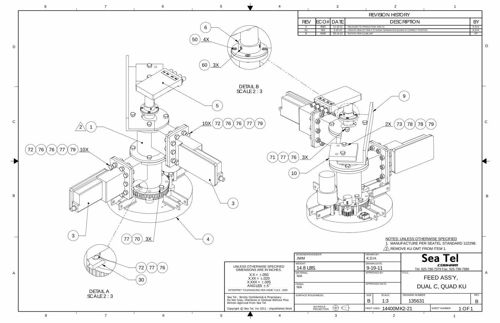
Written Approval From Sea Tel.
Sea Tel - Strictly Confidential & Proprietary.Do Not Copy, Distribute or Disclose Without Prior
Copyright c Sea Tel, Inc 2011 - Unpublished Work
UNLESS OTHERWISE SPECIFIEDDIMENSIONS ARE IN INCHES.
.5
X.X = .050X.XX = .020
X.XXX = .005ANGLES:
INTERPRET TOLERANCING PER ASME Y14.5 - 2009
2
NOTES: UNLESS OTHERWISE SPECIFIED1. MANUFACTURE PER SEATEL STANDARD 122298.
REMOVE KU OMT FROM ITEM 1.
K.D.H.RELEASED TO PRODUCTION, WAS X111-10-119082AK.D.H.UPDATE VIEW OF ITEM 4 TO SHOW TERMINATION BOARD IN CORRECT POSITION2-22-12N/AA1
HTROTATE ITEM 5 (LNB) 18003-14-129430B
DETAIL B
50
60
SCALE 2 : 3
4X
3X
6
2X 78 79
10
7677
7873
9
3X71
3X
76 76
3
771
79
4
5
72
767672 79 10X77
3
7077
10X2
14.8 LBS.WEIGHT:
JWM
D
C
B
AA
B
C
D
12345678
8 7 6 5 4 3
SURFACE ROUGHNESS:
2 1
PROJECTION
FINISH:
MATERIAL:
DRAWN BY:
APPROVED BY: TITLE:
FIRST USED:
SIZE SCALE:
SHEET NUMBER
DRAWING NUMBER REV
B
K.D.H.
9-19-11
1:3 135631 B14400MK2-21 1 OF 1
DRAWN DATE:
APPROVED DATE:
FEED ASS'Y,
REVISION HISTORYREV ECO# DATE DESCRIPTION BY
DUAL C, QUAD KU
Tel. 925-798-7979 Fax. 925-798-7986
N/A
N/A
3rd ANGLE
DESIGNER/ENGINEER:
SCALE 2 : 3
77
30
DETAIL A
72 76

SINGLE LEVEL MFG BILL OF MATERIAL
FIND QTY PART NO REV DESCRIPTION REFERENCE DESIGNATOR
1 1 EA 131057-3 E1 ENCLOSURE ASS'Y, PCU, 09G2, 3 CH, 422
2 1 EA 134130 A1 MOUNTING PLATE, TVRO SWITCH
3 1 EA 128204-1 C RF SWITCH ASSEMBLY
4 1 EA 131227-1 C ENCLOSURE ASS'Y, MOTOR DRIVER, 09G2
5 4 EA 135639 A1 BAR, MK2 PCU MOUNTING, TVRO
6 2 EA 125150-021 A1 UNISTRUT, 1-1/4 H-CHANNEL, 21 IN, AL
8 12 EA 125151-1 A1 NUT, 1 1/4 UNISTRUT, 1/4-20, W/SPRING
10 2 EA 109391 A ADAPTER, F(F)-F(F) (BULLET), 0.84 IN
11 2 EA 111679-2 B CABLE CLAMP, NYLON, 3/16 DIA, #8 MTG
50 2 EA 114588-107 SCREW, PAN HD, PHIL, 4-40 x 5/16, S.S
51 2 EA 114588-108 SCREW, PAN HD, PHIL, 4-40 x 3/8, S.S.
58 4 EA 114580-005 WASHER, FLAT, #4, S.S.
60 4 EA 119745-220 SCREW, PAN HD, PHIL, M4 X10, S.S.
68 4 EA 114580-230 WASHER, FLAT, M4, S.S.
70 8 EA 114586-537 SCREW, HEX HD, 1/4-20 x 3/4, S.S.
71 2 EA 114586-543 SCREW, HEX HD, 1/4-20 x 2, S.S.
72 2 EA 114586-545 SCREW, HEX HD, 1/4-20 x 2-1/2, S.S.
76 8 EA 114581-029 WASHER, LOCK, 1/4, S.S
77 8 EA 114580-027 WASHER, FLAT, 1/4, SMALL PATTERN, S.S
78 12 EA 114580-029 WASHER, FLAT, 1/4, S.S.
80 8 EA 114593-207 SCREW, SOCKET HD, 1/4-20 x 3/4, S.S.
2SHT 1 OF
MOUNTING ASS'Y, MK2 PCU, TVRO PROD FAMILY
COMMON EFF. DATE4/11/2012
DRAWINGNUMBER135632-1
REV B
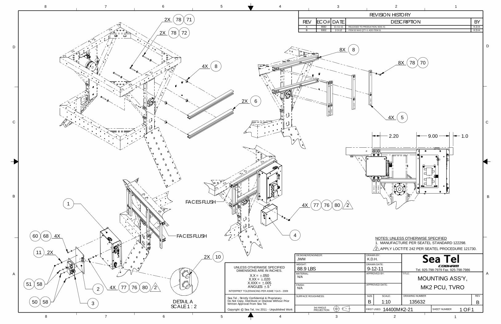
Written Approval From Sea Tel.
Sea Tel - Strictly Confidential & Proprietary.Do Not Copy, Distribute or Disclose Without Prior
Copyright c Sea Tel, Inc 2011 - Unpublished Work
UNLESS OTHERWISE SPECIFIEDDIMENSIONS ARE IN INCHES.
.5
X.X = .050X.XX = .020
X.XXX = .005ANGLES:
INTERPRET TOLERANCING PER ASME Y14.5 - 2009
NOTES: UNLESS OTHERWISE SPECIFIED1. MANUFACTURE PER SEATEL STANDARD 122298.
APPLY LOCTITE 242 PER SEATEL PROCEDURE 121730.2
K.D.H.RELEASED TO PRODUCTION, WAS X111-11-119082AK.D.H.ITEM 50 WAS QTY 4; ADD ITEM 512-3-129302B
SCALE 1 : 2DETAIL A
2X 10
9.00 1.0 2.20
77 76 80FACES FLUSH
4
4X 2
11
FACES FLUSH
1
277
4X
762
6860
4X
3
80
2X
5851
78
5
708X
4X
8X 8
8
722X
78
2X 6
4X
78
2X 71
5850
JWM
D
C
B
AA
B
C
D
12345678
8 7 6 5 4 3 2 1
WEIGHT:
PROJECTION
FINISH:
MATERIAL:
DRAWN BY:
APPROVED BY: TITLE:
FIRST USED:
SIZE SCALE:
SHEET NUMBER
DRAWING NUMBER REV
B
K.D.H.
9-12-11
1:10 135632 B14400MK2-21 1 OF 1
DRAWN DATE:
APPROVED DATE:
MOUNTING ASS'Y,
REVISION HISTORYREV ECO# DATE DESCRIPTION BY
MK2 PCU, TVRO
Tel. 925-798-7979 Fax. 925-798-7986
N/A
N/A
SURFACE ROUGHNESS:
88.9 LBS
3rd ANGLE
DESIGNER/ENGINEER:
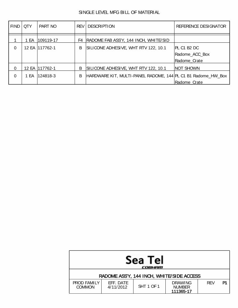
SINGLE LEVEL MFG BILL OF MATERIAL
FIND QTY PART NO REV DESCRIPTION REFERENCE DESIGNATOR
1 1 EA 109119-17 F4 RADOME FAB ASS'Y, 144 INCH, WHITE/SID
0 12 EA 117762-1 B SILICONE ADHESIVE, WHT RTV 122, 10.1 PL C1 B2 DCRadome_ACC_BoxRadome_Crate
0 12 EA 117762-1 B SILICONE ADHESIVE, WHT RTV 122, 10.1 NOT SHOWN
0 1 EA 124818-3 B HARDWARE KIT, MULTI-PANEL RADOME, 144 PL C1 B1 Radome_HW_BoxRadome_Crate
1SHT 1 OF
RADOME ASS'Y, 144 INCH, WHITE/SIDE ACCESS PROD FAMILY
COMMON EFF. DATE4/11/2012
DRAWINGNUMBER
111365-17
REV P1
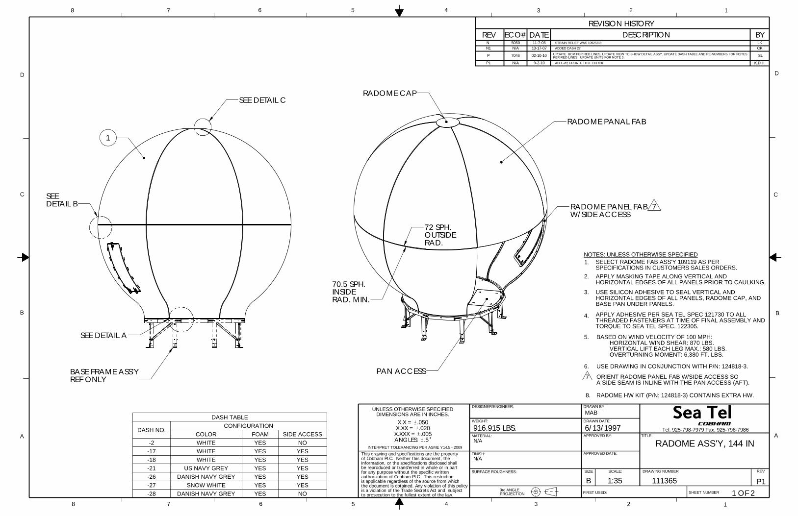
SELECT RADOME FAB ASS'Y 109119 AS PERSPECIFICATIONS IN CUSTOMERS SALES ORDERS.
1.NOTES: UNLESS OTHERWISE SPECIFIED
2. APPLY MASKING TAPE ALONG VERTICAL ANDHORIZONTAL EDGES OF ALL PANELS PRIOR TO CAULKING.
USE SILICON ADHESIVE TO SEAL VERTICAL ANDHORIZONTAL EDGES OF ALL PANELS, RADOME CAP, AND BASE PAN UNDER PANELS.
3.
APPLY ADHESIVE PER SEA TEL SPEC 121730 TO ALLTHREADED FASTENERS AT TIME OF FINAL ASSEMBLY AND TORQUE TO SEA TEL SPEC. 122305.
4.
BASED ON WIND VELOCITY OF 100 MPH: HORIZONTAL WIND SHEAR: 870 LBS. VERTICAL LIFT EACH LEG MAX.: 580 LBS. OVERTURNING MOMENT: 6,380 FT. LBS.
5.
USE DRAWING IN CONJUNCTION WITH P/N: 124818-3.6.
ORIENT RADOME PANEL FAB W/SIDE ACCESS SOA SIDE SEAM IS INLINE WITH THE PAN ACCESS (AFT).
7
RADOME HW KIT (P/N: 124818-3) CONTAINS EXTRA HW.8.
LKSTRAIN RELIEF WAS 109258-811-7-055050N CKADDED DASH 2710-17-07N/AN1
SLUPDATE BOM PER RED LINES. UPDATE VIEW TO SHOW DETAIL ASSY. UPDATE DASH TABLE AND RE-NUMBERS FOR NOTES PER RED LINES. UPDATE UNITS FOR NOTE 5.02-10-107046P
K.D.H.ADD -28; UPDATE TITLE BLOCK.9-2-10N/AP1
DASH TABLE
DASH NO.CONFIGURATION
COLOR FOAM SIDE ACCESS-2 WHITE YES NO
-17 WHITE YES YES-18 WHITE YES YES-21 US NAVY GREY YES YES-26 DANISH NAVY GREY YES YES-27 SNOW WHITE YES YES-28 DANISH NAVY GREY YES NO
X.XXX = .020X.XX =
D
C
B
AA
B
C
D
12345678
8 7 6 5 4 3
WEIGHT:
DESIGNER/ENGINEER:
PROJECTION
FINISH:
MATERIAL:
DRAWN BY:
APPROVED BY: TITLE:
FIRST USED:
SIZE SCALE:
SHEET NUMBER
DRAWING NUMBER REV
B
MAB
6/13/1997
1:35 111365 P11 OF 2
DRAWN DATE:
APPROVED DATE:
RADOME ASS'Y, 144 IN
REVISION HISTORYREV ECO# DATE DESCRIPTION BY
2 1
.5INTERPRET TOLERANCING PER ASME Y14.5 - 2009
916.915 LBS.
UNLESS OTHERWISE SPECIFIED
Tel. 925-798-7979 Fax. 925-798-7986
SURFACE ROUGHNESS:
.005ANGLES: N/A
N/A
3rd ANGLE
DIMENSIONS ARE IN INCHES.X.X = .050
This drawing and specifications are the property of Cobham PLC. Neither this document, the information, or the specifications disclosed shall be reproduced or transferred in whole or in part for any purpose without the specific written authorization of Cobham PLC. This restriction is applicable regardless of the source from which the document is obtained. Any violation of this policy is a violation of the Trade Secrets Act and subject to prosecution to the fullest extent of the law.
DETAIL B
SEE DETAIL C
SEE DETAIL A
SEE
1
BASE FRAME ASS'YREF ONLY
PAN ACCESS
INSIDE
W/SIDE ACCESS
RADOME CAP
OUTSIDE
RADOME PANAL FAB
72 SPH.
RAD.
RAD. MIN.
70.5 SPH.
RADOME PANEL FAB 7

D
C
B
AA
B
C
D
12345678
8 7 6 5 4 3 2 1
SIZE SCALE:
SHEET NUMBER
DRAWING NUMBER REV
B 1:64 111365 P12 OF 2
P/N: 131731-1 KIT, RADOME PANEL TO BASE FRAME, 75 IN
SCALE 1 : 8
P/N: 131730-3 KIT, RADOME PANELS, 144 IN
DETAIL B
52TOP RAOME PANEL 50
50102X 52
204X
BOTTOM RADOME PANEL
52
SCALE 1 : 8DETAIL A
5160X
BASE PAN FAB
52
SCALE 1 : 8
P/N: 131729-2 KIT, RADOME CAP, 126, 144 IN
DETAIL C RADOME PANEL
506X
RADOME CAP
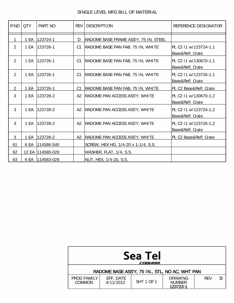
SINGLE LEVEL MFG BILL OF MATERIAL
FIND QTY PART NO REV DESCRIPTION REFERENCE DESIGNATOR
1 1 EA 123724-1 D RADOME BASE FRAME ASS'Y, 75 IN, STEEL
2 1 EA 123726-1 C1 RADOME BASE PAN FAB, 75 IN, WHITE PL C2 I1 w/123724-1,1Base&Refl_Crate
2 1 EA 123726-1 C1 RADOME BASE PAN FAB, 75 IN, WHITE PL C2 I1 w/130670-1,1Base&Refl_Crate
2 1 EA 123726-1 C1 RADOME BASE PAN FAB, 75 IN, WHITE PL C2 I1 w/123726-1,1Base&Refl_Crate
2 1 EA 123726-1 C1 RADOME BASE PAN FAB, 75 IN, WHITE PL C2 Base&Refl_Crate
3 1 EA 123728-2 A2 RADOME PAN ACCESS ASS'Y, WHITE PL C2 I1 w/130670-1,2Base&Refl_Crate
3 1 EA 123728-2 A2 RADOME PAN ACCESS ASS'Y, WHITE PL C2 I1 w/123724-1,2Base&Refl_Crate
3 1 EA 123728-2 A2 RADOME PAN ACCESS ASS'Y, WHITE PL C2 I1 w/123726-1,2Base&Refl_Crate
3 1 EA 123728-2 A2 RADOME PAN ACCESS ASS'Y, WHITE PL C2 Base&Refl_Crate
61 6 EA 114586-540 SCREW, HEX HD, 1/4-20 x 1-1/4, S.S.
62 12 EA 114580-029 WASHER, FLAT, 1/4, S.S.
63 6 EA 114583-029 NUT, HEX, 1/4-20, S.S.
1SHT 1 OF
RADOME BASE ASS'Y, 75 IN., STL, NO AC, WHT PAN PROD FAMILY
COMMON EFF. DATE4/11/2012
DRAWINGNUMBER123723-1
REV D
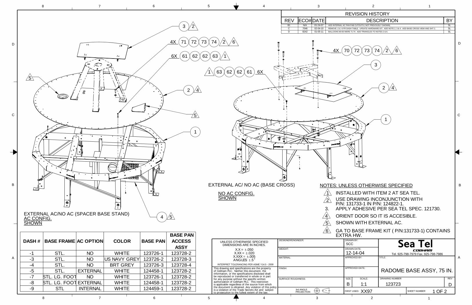
SLADD INTERNAL AC PAN FAB CUTOUTS ( NOT PREVOUSLY SHOWN).01-24-07N/AB1SLREMOVE -2 & -6 FR DASH TABLE. UPDATE HARDWARE KIT. ADD NOTE 2, 3 & 4. ADD BASE CROSS VIEW AND SHT 2.02-04-107046CSLBALLOONS 80-83 WERE 71-74. ADD TRIANGLES TO NOTES 2 & 6.01-05-118242D
.020X.XX =
D
C
B
AA
B
C
D
12345678
8 7 6 5 4 3 2
DESIGNER/ENGINEER:
PROJECTION
FINISH:
MATERIAL:
DRAWN BY:
APPROVED BY: TITLE:
FIRST USED:
SIZE SCALE:
SHEET NUMBER
DRAWING NUMBER REV
B
SCC
12-14-04
1:1 123723 DXX97 1 OF 2
DRAWN DATE:
APPROVED DATE:
REVISION HISTORYREV ECO# DATE DESCRIPTION BY
RADOME BASE ASSY, 75 IN.INTERPRET TOLERANCING PER ASME Y14.5 - 2009
1
3rd ANGLE
Tel. 925-798-7979 Fax. 925-798-7986X.XXX =
WEIGHT:
UNLESS OTHERWISE SPECIFIED
SURFACE ROUGHNESS:
.005ANGLES: .5
DIMENSIONS ARE IN INCHES.X.X = .050
This drawing and specifications are the property of Cobham PLC. Neither this document, the information, or the specifications disclosed shall be reproduced or transferred in whole or in part for any purpose without the specific written authorization of Cobham PLC. This restriction is applicable regardless of the source from which the document is obtained. Any violation of this policy is a violation of the Trade Secrets Act and subject to prosecution to the fullest extent of the law.
INSTALLED WITH ITEM 2 AT SEA TEL.NOTES: UNLESS OTHERWISE SPECIFIED
P/N: 131733-1 IN P/N: 124822-1.
1
3. APPLY ADHESIVE PER SEA TEL SPEC. 121730.
2 USE DRAWING INCONJUNCTION WITH
ORIENT DOOR SO IT IS ACCESIBLE.4SHOWN WITH EXTERNAL AC.5
6 GA TO BASE FRAME KIT ( P/N:131733-1) CONTAINS EXTRA HW.
1
2
5
7471 724X 73
5
3
61 62 62 63
AC CONFIG.SHOWN
1
2
EXTERNAL AC/NO AC (SPACER BASE STAND)
4
4
6X
5
6
2
1
74
1
70 72
EXTERNAL AC/ NO AC (BASE CROSS)
3
2
SHOWN
73
4
24X
61626263
NO AC CONFIG.
6X
6
DASH # BASE FRAME AC OPTION COLOR BASE PAN BASE PAN
ACCESS ASSY
-1 STL. NO WHITE 123726-1 123728-2-3 STL. NO US NAVY GREY 123726-2 123728-3-4 STL. NO BRT GREY 123726-3 123728-4-5 STL. EXTERNAL WHITE 124458-1 123728-2-7 STL. LG. FOOT NO WHITE 123726-1 123728-2-8 STL. LG. FOOT EXTERNAL WHITE 124458-1 123728-2-9 STL INTERNAL WHITE 124459-1 123728-2
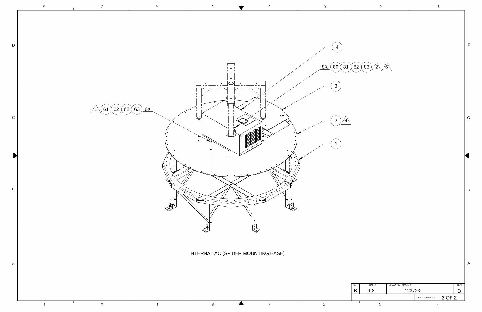
D
C
B
AA
B
C
D
12345678
8 7 6 5 4 3 2 1
SIZE SCALE:
SHEET NUMBER
DRAWING NUMBER REV
B 1:8 123723 D2 OF 2
1
3
INTERNAL AC (SPIDER MOUNTING BASE)
8X 80 81 82 83
4
6X63626261
2 4
1
2 6

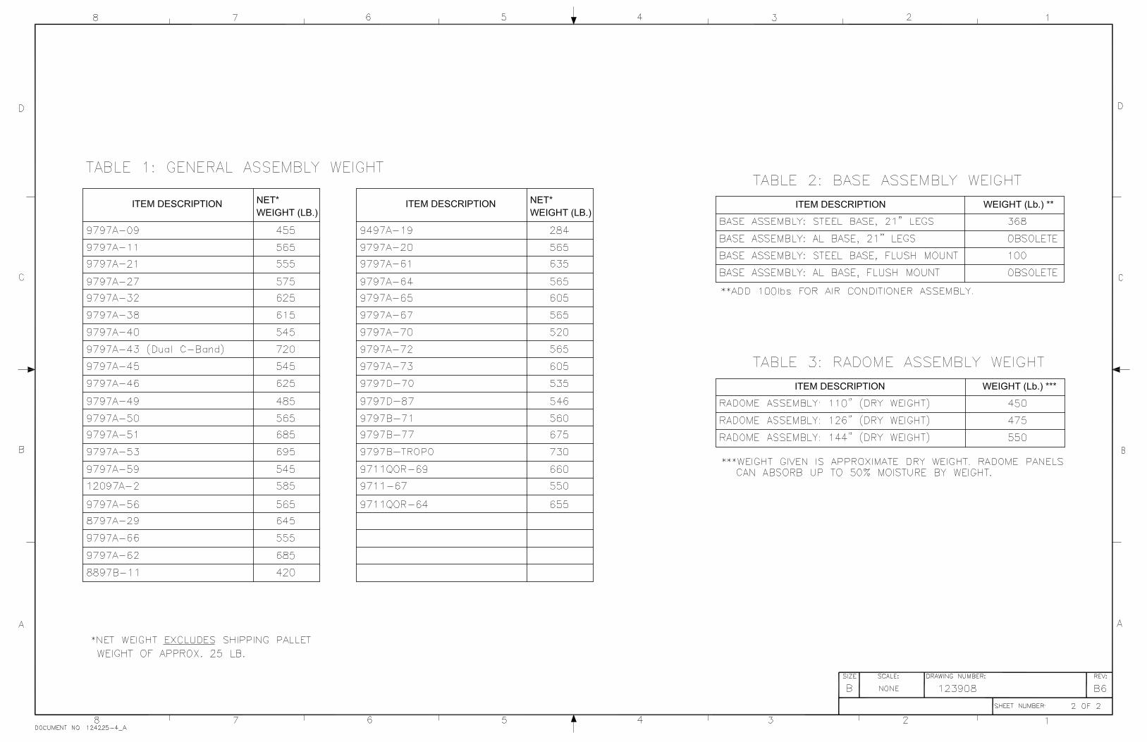

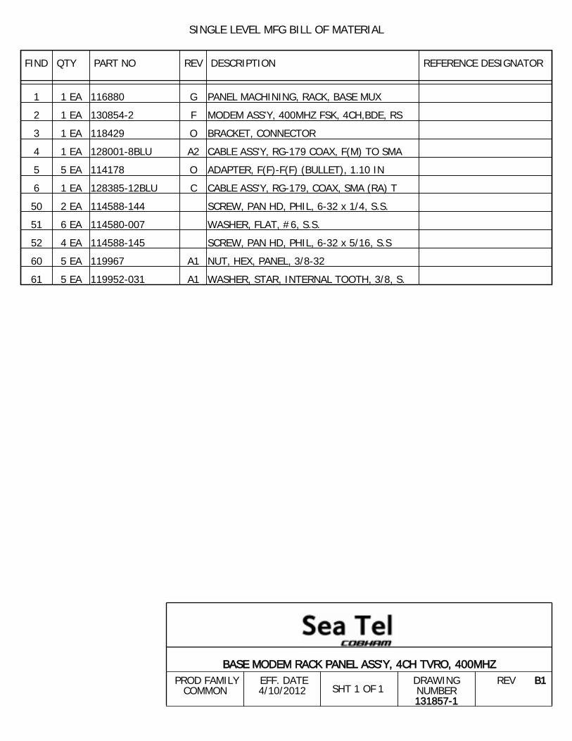
SINGLE LEVEL MFG BILL OF MATERIAL
FIND QTY PART NO REV DESCRIPTION REFERENCE DESIGNATOR
1 1 EA 116880 G PANEL MACHINING, RACK, BASE MUX
2 1 EA 130854-2 F MODEM ASS'Y, 400MHZ FSK, 4CH,BDE, RS
3 1 EA 118429 O BRACKET, CONNECTOR
4 1 EA 128001-8BLU A2 CABLE ASS'Y, RG-179 COAX, F(M) TO SMA
5 5 EA 114178 O ADAPTER, F(F)-F(F) (BULLET), 1.10 IN
6 1 EA 128385-12BLU C CABLE ASS'Y, RG-179, COAX, SMA (RA) T
50 2 EA 114588-144 SCREW, PAN HD, PHIL, 6-32 x 1/4, S.S.
51 6 EA 114580-007 WASHER, FLAT, #6, S.S.
52 4 EA 114588-145 SCREW, PAN HD, PHIL, 6-32 x 5/16, S.S
60 5 EA 119967 A1 NUT, HEX, PANEL, 3/8-32
61 5 EA 119952-031 A1 WASHER, STAR, INTERNAL TOOTH, 3/8, S.
1SHT 1 OF
BASE MODEM RACK PANEL ASS'Y, 4CH TVRO, 400MHZ PROD FAMILY
COMMON EFF. DATE4/10/2012
DRAWINGNUMBER131857-1
REV B1

Written Approval From Sea Tel.
Sea Tel - Strictly Confidential & Proprietary.Do Not Copy, Distribute or Disclose Without Prior
Copyright c Sea Tel, Inc 2011 - Unpublished Work
UNLESS OTHERWISE SPECIFIEDDIMENSIONS ARE IN INCHES.
.5
X.X = .050X.XX = .020
X.XXX = .005ANGLES:
INTERPRET TOLERANCING PER ASME Y14.5 - 2009
SLITEM 50 QTY WS 6. ADD ITEM 52. UPDATE NOTES.02-14-118180B
MANUFACTURE PER SEA TEL SPEC 122298.1.NOTES: UNLESS OTHERWISE SPECIFIED
2. IDENTIFY PER SEATEL SPECIFICATION 122930 ( APPENDIX D) APPROX WHERE SHOWN.
SLBALLOON 52 WAS 50. 04-18-11N/AB1
52 51
61
2X51
1
4X
5X
2
50
3
4
60
5 5X
5X
2
6
Tel. 925-798-7979 Fax. 925-798-7986
N/A
N/A
SURFACE ROUGHNESS:
WEIGHT:
D
C
B
AA
B
C
D
12345678
8 7 6 5
ASS'Y, 4CH TVRO, 400MHZ
4 3 2 1
PROJECTION
FINISH:
MATERIAL:
DRAWN BY:
APPROVED BY: TITLE:
FIRST USED:
SIZE SCALE:
SHEET NUMBER
DRAWING NUMBER REV
B
K.D.H.
2-23-10
1:1.5 131857 B114400B-21 1 OF 1
DRAWN DATE:
APPROVED DATE:
BASE MODEM RACK PANEL
REVISION HISTORYREV ECO# DATE DESCRIPTION BY
3rd ANGLE
DESIGNER/ENGINEER: