Embed Size (px)
Citation preview
051812/ Ver. A TL-100047
Installation and Operation Manual Mobile Services Suite
2
Contents 1. Introduction ...................................................................................................................... 5
1.1. General ................................................................................................................................. 5
1.2. License for MSS ................................................................................................................... 5
2. Features ............................................................................................................................... 7
2.1. Reminders............................................................................................................................. 7
2.1.1. Description..................................................................................................................... 7
2.1.2. Functionality .................................................................................................................. 9
2.1.2.1. Reminder Timeout .................................................................................................. 9
2.1.2.2. Snooze ..................................................................................................................... 9
2.1.2.3. Lookup .................................................................................................................. 10
2.1.2.4. Custom Reminders ................................................................................................ 11
2.1.2.5. Default Reminders ................................................................................................ 11
2.1.2.6. Active Reminders Limit ........................................................................................ 12
2.2. Assist Request .................................................................................................................... 13
2.2.1. Description................................................................................................................... 13
2.2.2. Functionality ................................................................................................................ 16
2.2.2.1. Minimum Number of Accepts .............................................................................. 16
2.2.2.2. Assist Request Timeout ........................................................................................ 16
2.2.2.3. Retry Interval ........................................................................................................ 17
2.2.2.5. Default Assist Requests ........................................................................................ 18
2.2.2.6. Active Assist Requests Limit ................................................................................ 19
2.3. Conference Request............................................................................................................ 20
2.3.1. Description................................................................................................................... 20
2.3.2. Functionality ................................................................................................................ 21
2.3.2.1. Interactive ............................................................................................................. 21
2.3.2.2. Manual and Auto................................................................................................... 21
2.3.2.3. Originator Join Update .......................................................................................... 22
2.3.2.4. Default Conference Requests ................................................................................ 22
2.3.2.5. Originator Message Type ...................................................................................... 24

3
2.4. Groups ................................................................................................................................ 25
2.5. Alarm Block ....................................................................................................................... 26
3. UCM Installation and Configuration ............................................................. 27
3.1. Introduction ........................................................................................................................ 27
3.2. Mounting, Power Supply, and Connections ....................................................................... 27
3.3. Accessing Elise3 ................................................................................................................ 27
3.3.1. Access via the Network ............................................................................................... 27
3.3.2. Access via the Management port ................................................................................. 28
3.3.2.1. Install the Port Driver on Windows XP/Vista....................................................... 29
3.3.2.2. Install the Port Driver on Windows 7 ................................................................... 30
3.4. Basic Configuration............................................................................................................ 32
3.4.1. Log on to UCM............................................................................................................ 32
3.4.2. Add Users .................................................................................................................... 33
3.4.2.1. Import Users From a CSV File ............................................................................. 34
3.4.2.2. Additional User Settings ....................................................................................... 35
3.4.3. Groups ......................................................................................................................... 37
3.4.3.1. Create a Single Group ........................................................................................... 38
3.4.3.2. Add Members to a Group ..................................................................................... 39
3.4.4. Backup the Configuration ............................................................................................ 40
3.4.5. Restore the Configuration ............................................................................................ 40
4. Configure the UCM for MSS ............................................................................... 41 5. MSS Installation ........................................................................................................... 42
6. Upgrading the MSS Application ........................................................................ 42
7. Backup/Restore MSS Database .......................................................................... 43
8. Handset Configuration ............................................................................................. 43
8.1. How to Create a Service ..................................................................................................... 43
8.2. How to Delete a Service ..................................................................................................... 43
8.3. Adding Predefined MSS Services ...................................................................................... 43
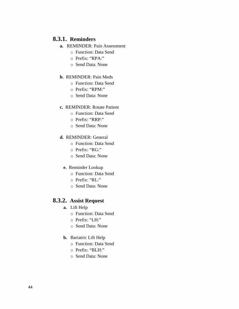
8.3.1. Reminders .................................................................................................................... 44
4
8.3.2. Assist Request.............................................................................................................. 44
8.3.3. Conference Request ..................................................................................................... 45
9. MSS Configuration ..................................................................................................... 46
9.1. Reminders........................................................................................................................... 46
9.2. Reminder Global Timers .................................................................................................... 48
9.3. Assist Requests ................................................................................................................... 49
9.4. Assist Request Global Timer ............................................................................................. 52
9.5. Conference Requests .......................................................................................................... 53
9.6. Groups ................................................................................................................................ 57
9.7. Alarm Block ....................................................................................................................... 58
9.8. Message Text...................................................................................................................... 59
9.9. License ............................................................................................................................... 60
5
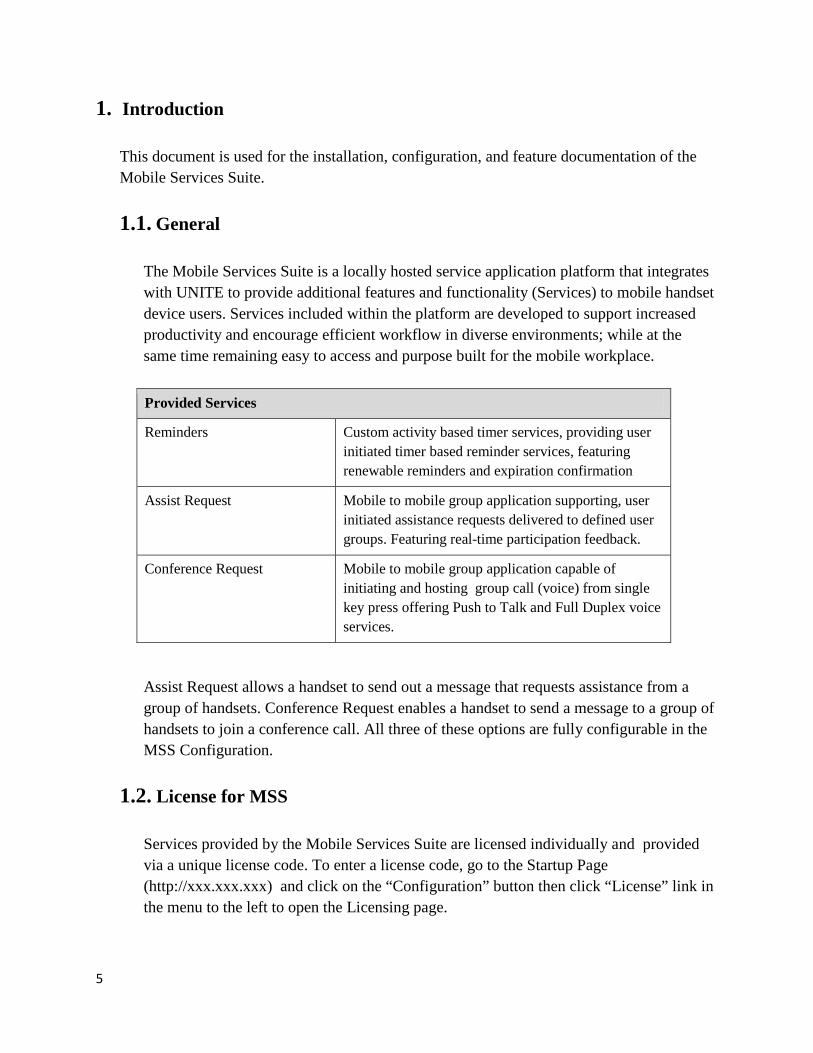
1. Introduction This document is used for the installation, configuration, and feature documentation of the Mobile Services Suite. 1.1. General
The Mobile Services Suite is a locally hosted service application platform that integrates with UNITE to provide additional features and functionality (Services) to mobile handset device users. Services included within the platform are developed to support increased productivity and encourage efficient workflow in diverse environments; while at the same time remaining easy to access and purpose built for the mobile workplace. Provided Services
Reminders Custom activity based timer services, providing user initiated timer based reminder services, featuring renewable reminders and expiration confirmation
Assist Request Mobile to mobile group application supporting, user initiated assistance requests delivered to defined user groups. Featuring real-time participation feedback.
Conference Request Mobile to mobile group application capable of initiating and hosting group call (voice) from single key press offering Push to Talk and Full Duplex voice services.
Assist Request allows a handset to send out a message that requests assistance from a group of handsets. Conference Request enables a handset to send a message to a group of handsets to join a conference call. All three of these options are fully configurable in the MSS Configuration.
1.2. License for MSS
Services provided by the Mobile Services Suite are licensed individually and provided via a unique license code. To enter a license code, go to the Startup Page (http://xxx.xxx.xxx) and click on the “Configuration” button then click “License” link in the menu to the left to open the Licensing page.

6
Figure 1. Licensing page

7
2. Features
2.1. Reminders The Reminder service enables handset users to create reminders that wait a specific number of minutes (entered by user) before sending a reminder message to the handset.
Figure 2. Example of workflow when creating a Reminder.
2.1.1. Description
The user creates a Reminder by selecting a predefined Services Menu item. The user will need to enter in the location and the number minutes the MSS will wait before sending the reminder. When the user is prompted by the handset to enter data they will use the following format: <location>#<wait minutes>.
Figure 3. Example of entering data when creating a Reminder. The location is room number 6123
and the MSS should wait 10 minutes before sending the handset a reminder message.

8
The “location” will be displayed at the end of the reminder message text. The “wait minutes” is the number of minutes that the MSS will wait before sending the reminder message to the handset.
After the number of wait minutes has passed the Reminder is considered to have expired and a message will be sent to the handset. The message will display the soft keys “Accept” and “Snooze”.
Figure 4. Example of Reminder message.
The MSS will continue to send messages for an expired Reminder at a set interval (the default is one minute) until one of three conditions has been met:
a) the Reminder has timed out b) user has accepted the Reminder c) user has set Reminder to snooze
Whether a Reminder is deleted from the handset after it has been accepted or timed out is configurable in the MSS Configuration. Reminder Example A user wants to create a reminder to rotate a patient in room 2678 in 20 minutes. The user will select the “Menu” soft key then select the “Services” item. From the Services Menu, the user will need to select the item assigned to Rotate Patient Reminder. The user will then be prompted to enter data. The user would enter in the following: “2678#20”. After the 20 minutes has passed the handset will receive a Rotate Patient reminder that includes the location.
9
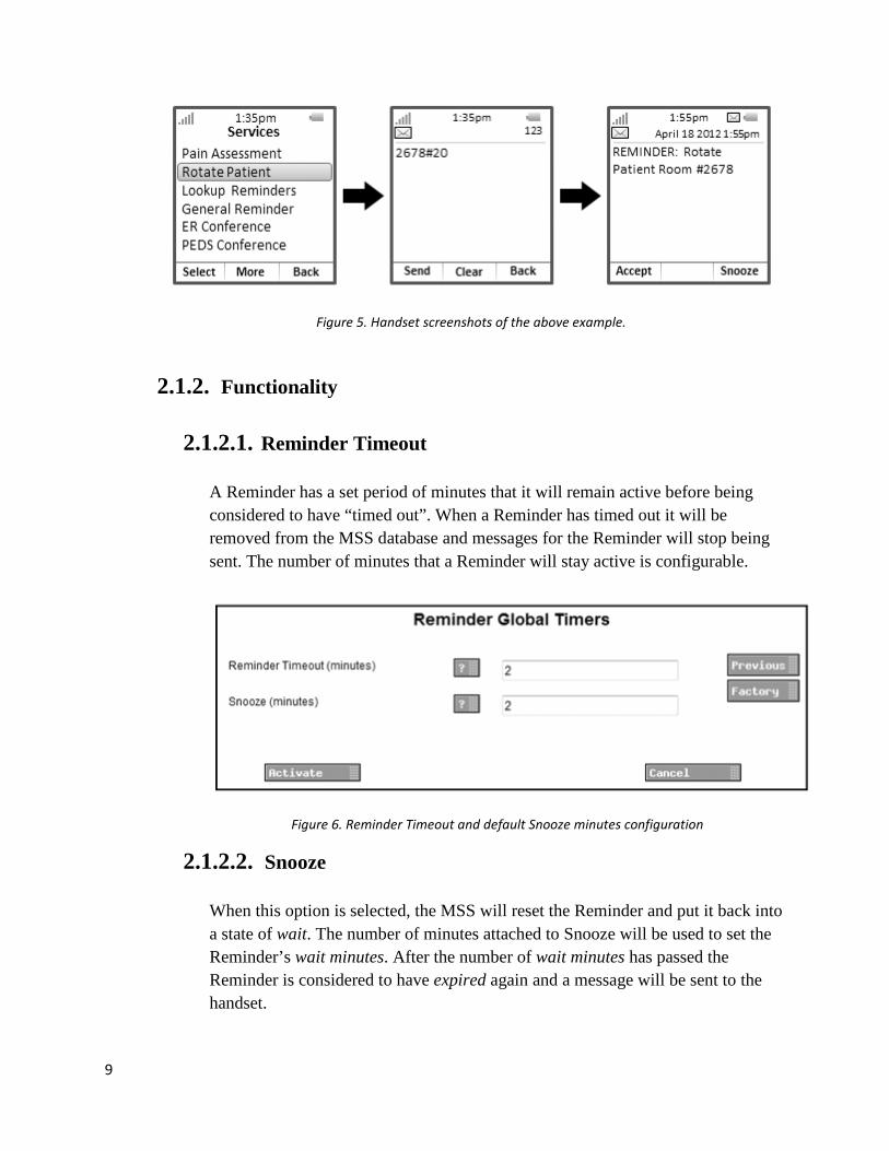
Figure 5. Handset screenshots of the above example.
2.1.2. Functionality
2.1.2.1. Reminder Timeout
A Reminder has a set period of minutes that it will remain active before being considered to have “timed out”. When a Reminder has timed out it will be removed from the MSS database and messages for the Reminder will stop being sent. The number of minutes that a Reminder will stay active is configurable.
Figure 6. Reminder Timeout and default Snooze minutes configuration
2.1.2.2. Snooze When this option is selected, the MSS will reset the Reminder and put it back into a state of wait. The number of minutes attached to Snooze will be used to set the Reminder’s wait minutes. After the number of wait minutes has passed the Reminder is considered to have expired again and a message will be sent to the handset.
10
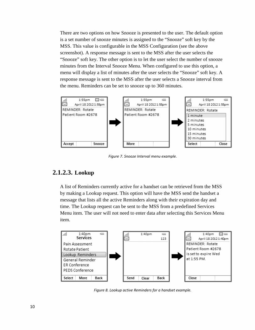
There are two options on how Snooze is presented to the user. The default option is a set number of snooze minutes is assigned to the “Snooze” soft key by the MSS. This value is configurable in the MSS Configuration (see the above screenshot). A response message is sent to the MSS after the user selects the “Snooze” soft key. The other option is to let the user select the number of snooze minutes from the Interval Snooze Menu. When configured to use this option, a menu will display a list of minutes after the user selects the “Snooze” soft key. A response message is sent to the MSS after the user selects a Snooze interval from the menu. Reminders can be set to snooze up to 360 minutes.
Figure 7. Snooze Interval menu example.
2.1.2.3. Lookup A list of Reminders currently active for a handset can be retrieved from the MSS by making a Lookup request. This option will have the MSS send the handset a message that lists all the active Reminders along with their expiration day and time. The Lookup request can be sent to the MSS from a predefined Services Menu item. The user will not need to enter data after selecting this Services Menu item.
Figure 8. Lookup active Reminders for a handset example.
11
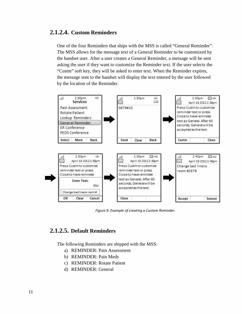
2.1.2.4. Custom Reminders One of the four Reminders that ships with the MSS is called “General Reminder”. The MSS allows for the message text of a General Reminder to be customized by the handset user. After a user creates a General Reminder, a message will be sent asking the user if they want to customize the Reminder text. If the user selects the “Custm” soft key, they will be asked to enter text. When the Reminder expires, the message sent to the handset will display the text entered by the user followed by the location of the Reminder.
Figure 9. Example of creating a Custom Reminder.
2.1.2.5. Default Reminders The following Reminders are shipped with the MSS:
a) REMINDER: Pain Assessment b) REMINDER: Pain Meds c) REMINDER: Rotate Patient d) REMINDER: General

12
Figure 10. List of Reminders that ships with the Mobile Services Suite.
2.1.2.6. Active Reminders Limit
There is a limit to the number of active Reminders that a handset can have at one time. The MSS ships with at a default limit of 10. The handset will receive a message if the user tries to create a Reminder after the limit has been reached.
Figure 11. Maximum Active Assist Request message.

13
2.2. Assist Request The Assist Request option allows a handset user to send out a message requesting assistance from a group of handsets.
Figure 12. Example of workflow when sending an Assist Request.
2.2.1. Description
The user creates the Assist Request by selecting a predefined Services Menu item. The user will need to enter a location when prompted to enter data. This location will be displayed at the end of the Assist Request message text.
For example, a user wants to send out a Lift Help request for room 1590. The user will select the “Menu” soft key then select the “Services” item. From the Services Menu, the user will need to select the item assigned to Lift Help. The user will then be prompted to enter data. The user would enter in the following: 1590.
Figure 13. Example of creating an Assist Request.

14
Assist Requests are assigned a group that will receive its messages. The group can be local (created in the MSS) or external (UCM group). The message sent to the group members will display two soft keys, “Accept” and “Busy”. If the receiver selects the “Accept” soft key, they will receive a confirmation message.
Figure 14. Example of Assist Request message receiver. This handset accepted the Assist Request so they received this confirmation message until the minimum number of accepting handsets has been reached.
If the receiver selects the “Busy” soft key, they will not receive another message unless the Retry Interval restarts before the Assist Request has timed out. The MSS can send the originator a silent update message after each acceptance by a group member. This message will list all the handset extensions that have accepted the Assist Request.
Figure 15. Example of update message sent to sender of Assist Request. After the initial Assist Request message is sent to group members, the MSS will send Retry messages to all the unresponsive handsets (those that have not selected the “Accept” or “Busy” soft keys).
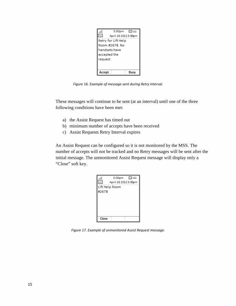
15
Figure 16. Example of message sent during Retry Interval.
These messages will continue to be sent (at an interval) until one of the three following conditions have been met:
a) the Assist Request has timed out b) minimum number of accepts have been received c) Assist Requests Retry Interval expires
An Assist Request can be configured so it is not monitored by the MSS. The number of accepts will not be tracked and no Retry messages will be sent after the initial message. The unmonitored Assist Request message will display only a “Close” soft key.
Figure 17. Example of unmonitored Assist Request message.

16
2.2.2. Functionality
2.2.2.1. Minimum Number of Accepts Assist Requests can be configure to require that they receive a minimum number of accepts before they are declared “Successful”. When the minimum number of accepts is reached a confirmation message will be sent to the accepting handsets. The originator of the Assist Request will receive a confirmation message that lists all the accepting handsets. Users who were unresponsive or selected “Busy” will have the Assist Request deleted from their handsets.
Figure 18. Confirmation message sent to acceptors of an Assist Request (after reaching accept minimum).
Figure 19. Confirmation message sent to originator of Assist Request (after reaching accept minimum).
2.2.2.2. Assist Request Timeout
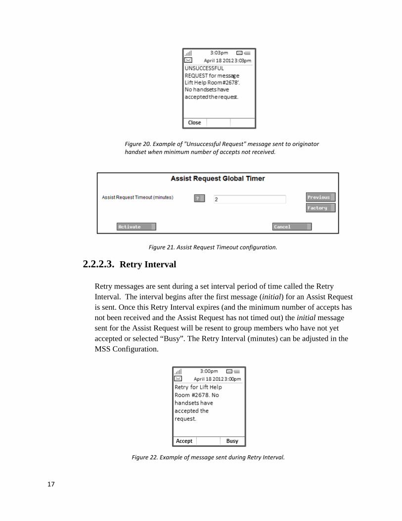
Assist Requests have a set period of minutes that they will remain active before being considered to have timed out. When an Assist Request has timed out (and has not received the minimum number of accepts) it will be removed from the MSS database and messages for it will stop being sent. The Assist Request will be deleted from all handsets that have received it. The originator will receive a message stating that the Assist Request was “Unsuccessful”. The number of minutes that an Assist Request will stay active is configurable.
17
Figure 20. Example of "Unsuccessful Request" message sent to originator handset when minimum number of accepts not received.
Figure 21. Assist Request Timeout configuration.
2.2.2.3. Retry Interval Retry messages are sent during a set interval period of time called the Retry Interval. The interval begins after the first message (initial) for an Assist Request is sent. Once this Retry Interval expires (and the minimum number of accepts has not been received and the Assist Request has not timed out) the initial message sent for the Assist Request will be resent to group members who have not yet accepted or selected “Busy”. The Retry Interval (minutes) can be adjusted in the MSS Configuration.
Figure 22. Example of message sent during Retry Interval.

18
2.2.2.4. Cancel The Cancel option allows the user to cancel the last active Assist Request that was created by their handset. The Cancel request is sent to the MSS from a predefined Services Menu item. The user will not need to enter data when making a Cancel request. The user will receive a confirmation message that displays the name and location of the Assist Request that they have cancelled. The receivers of the Assist Request will have it deleted from their handset.
Figure 23. Example of cancelling an Assist Request.
2.2.2.5. Default Assist Requests The following Assist Requests are shipped with the MSS:
a) Lift Help b) Bariatric Lift Help c) Need Assistance d) Pain Meds

19
Figure 24. List of Assist Requests that ships with the Mobile Services Suite.
2.2.2.6. Active Assist Requests Limit
There is a limit to the number active Assist Requests that a handset can have at one time. The handset will receive a message if the user tries to create an Assist Request after the limit has been reached. The MSS ships with a default limit of 10.
Figure 25. Maximum Active Assist Request message

20
2.3. Conference Request Conference Request allows a handset user to send a message to a group of handsets that will allow them to dial into a conference bridge to join a conference call.
Figure 26. Example of workflow when sending a Conference Request.
2.3.1. Description
A Conference Request is created by selecting a predefined Services Menu item. The user will not need to enter data when making this request.
Figure 27. Example of sending a Conference Request.
Conference Requests are assigned a group of handsets that will receive its messages. The group can be local (created in the MSS) or external (UCM group). The
21
originator of the Conference Request will also receive a message to join the call. Conference Request messages can be configure to use one of the three following Answer Modes: Interactive, Auto, and Manual. Note: The messages sent to group members and the originator are fully configurable in the MSS. Some of the configuration options available depend on the type of Answer Mode selected.
2.3.2. Functionality
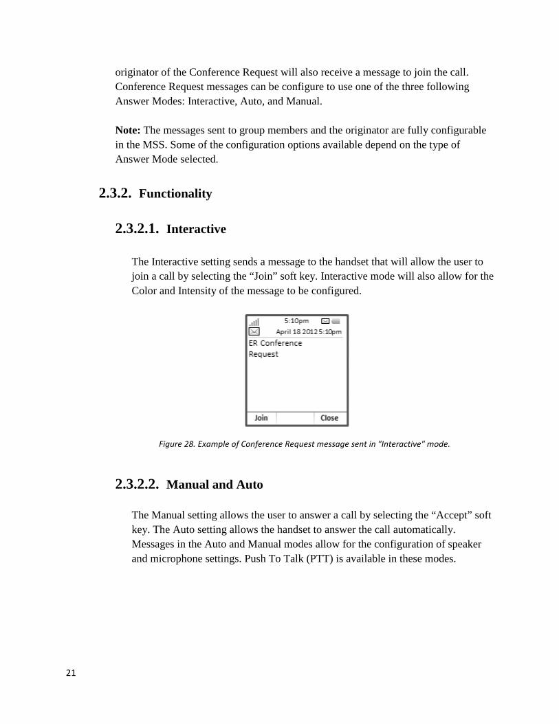
2.3.2.1. Interactive The Interactive setting sends a message to the handset that will allow the user to join a call by selecting the “Join” soft key. Interactive mode will also allow for the Color and Intensity of the message to be configured.
Figure 28. Example of Conference Request message sent in "Interactive" mode.
2.3.2.2. Manual and Auto
The Manual setting allows the user to answer a call by selecting the “Accept” soft key. The Auto setting allows the handset to answer the call automatically. Messages in the Auto and Manual modes allow for the configuration of speaker and microphone settings. Push To Talk (PTT) is available in these modes.

22
2.3.2.3. Originator Join Update The originator of a Conference Request can receive an update when a group member joins a conference call. The message sent to receivers must be configured to use the Answer Mode “Interactive”. The update message to the originator will contain a list of all the handsets that have joined the call.
Figure 31. Example of message received by the Originator of a Conference Request when a receiving group message had joined the conference call. This is available only when message sent to receivers is using the Answer Mode of “Interactive”.
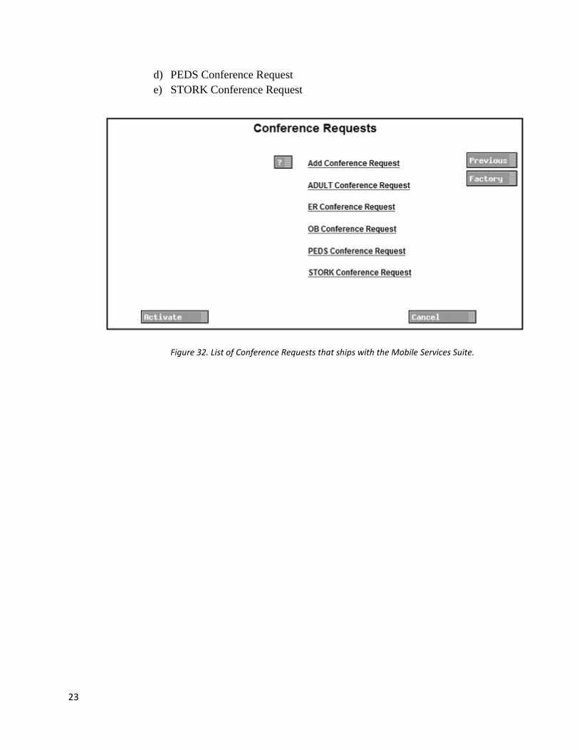
2.3.2.4. Default Conference Requests
The following Conference Requests are shipped with the MSS:
a) ADULT Conference Request b) ER Conference Request c) OB Conference Request
Figure 29. Example of message sent to originator of Conference Request when sent in "Manual" mode.
Figure 30. Example of message sent to receiving Group members of a Conference Request when sent in "Manual" mode.
23
d) PEDS Conference Request e) STORK Conference Request
Figure 32. List of Conference Requests that ships with the Mobile Services Suite.

24
2.3.2.5. Originator Message Type The originator of a Conference Request can receive the same or different type of message as the group members. If receiving a different type, the message parameters are fully configurable.
Figure 33. Configuration page for setting message parameters when the Originator of a Conference Request is receiving a different message type than the receiving group members
.

25
2.4. Groups Groups are a collection of handsets that can receive the same message from an Assist Request or Conference Request. The MSS allows for the creation of handset groups that are considered local to the application. They can be maintained using the MSS Configuration pages. Assist Requests and Conference Requests can also use external groups (UCM Groups).
Figure 34. Groups configuration page.
Note: It is recommended to use local groups in order to get the best performance from the MSS functionality.

26
2.5. Alarm Block The MSS allows for Assist Requests and Conference Requests to be assigned to the handset’s Alarm Button. You can assign these options to either “Push Button Alarm 1” (push and hold the Alarm Button) or “Push Button Alarm 2” (push the Alarm Button twice). If you assign an Assist Request to an Alarm you will also be required to assign a location.
Figure 35. Alarm Block configuration.
27
3. UCM Installation and Configuration
3.1. Introduction This is a general description for setting up a UCM (Elise3). For a more comprehensive guide please refer to “Elise3 Installation Guide” (TD 92679EN) and “UCM Installation and Operation Manual” (TD 92735EN).
3.2. Mounting, Power Supply, and Connections A guide to mounting, setting up the power supply, and establishing connections is found in the “Elise3 Installation Guide” (TD 92679EN).
3.3. Accessing Elise3 The Elise3 can be accessed either via an IP network or directly via the management port (mini-USB). The web browser Internet Explorer 8.0™ or later is used for accessing the product´s web interface.
3.3.1. Access via the Network
It is recommended that this module always gets the same IP address if it communicates with other equipment, to prevent it from losing contact with the equipment after a restart. Inform the network administrator about the MAC address and ask to reserve a fixed IP address via DHCP for this module. Write the IP address on the blank label, found on the back side of the Getting Started and Safety document and attach the label on the front side to facilitate future access.
Note: If NetBIOS is enabled in the network, the address elise XXXXXXXX can be used when accessing the module via the network, where XXXXXXXX is the module key number. The module key number can be found on the license certificate or on the label on the back of the module. Pre-condition: You have access to the network that Elise3 is attached to. If not, go to Section 3.3.2, Access via the Management port. 1. Connect the module to the LAN.
2. Open the web browser and enter the modules IP address or elise-
XXXXXXXX, where XXXXXXXX is the module key number (leading zeros

28
can be excluded). The module key number can be found on the license certificate or on the label on the back of the module.
3. Continue in 3.4 Basic Configuration.
3.3.2. Access via the Management port
Figure 36. Connection via the Management port.
The management port can be used when Elise3 has not got a valid and unique IP address or when the IP address has been changed, i.e. if Elise3 has been moved from one network to another. It gives access to the module without having access to the customer’s network. Note: The reserved IP address for accessing Elise3 via the management port is “192.5.36.229”. Note: A port driver needs to be installed on your PC to get access via the management port. The driver is located on the module. The default mode for the management port is Network access but Mass storage is used to get the required driver for the module. When set to Mass storage, the module will automatically change to Network access within 10 minutes. By pressing the Mode button twice, the Management port toggles from Network access to Mass storage and the other way around. The Mass storage mode is only used when the driver, required for accessing the module via the management port, shall be installed. This is only needed the first time the PC is used for this purpose. 1. Connect a mini-USB type B cable between the USB port on your PC and the
management port on the module. Note: If the required port driver is not installed on the PC, install it now. The
29
installation differs dependent on the operating system, see either Install the Port Driver on Windows XP/Vista or Install the Port Driver on Windows 7 below.
2. Open a web browser on your PC and enter the IP address “192.5.36.229" in the address field to access the products web interface.
3. Continue in 3.4 Basic Configuration.
3.3.2.1. Install the Port Driver on Windows XP/Vista Note: When switching between mass storage mode and network mode, it takes about 30 seconds before the module can be accessed with the 192.5.36.229 address. 1. Connect a mini-USB type B cable between the USB port in your PC and the
management port on the module. The Found new hardware wizard opens but at this stage there is no valid port driver so close the wizard and continue to install the driver.
2. Press the Mode button twice to change the mode to mass storage. The module will now turn up as a mass storage device on your computer. This is indicated by slowing flashing blue light on the Mode button LED.
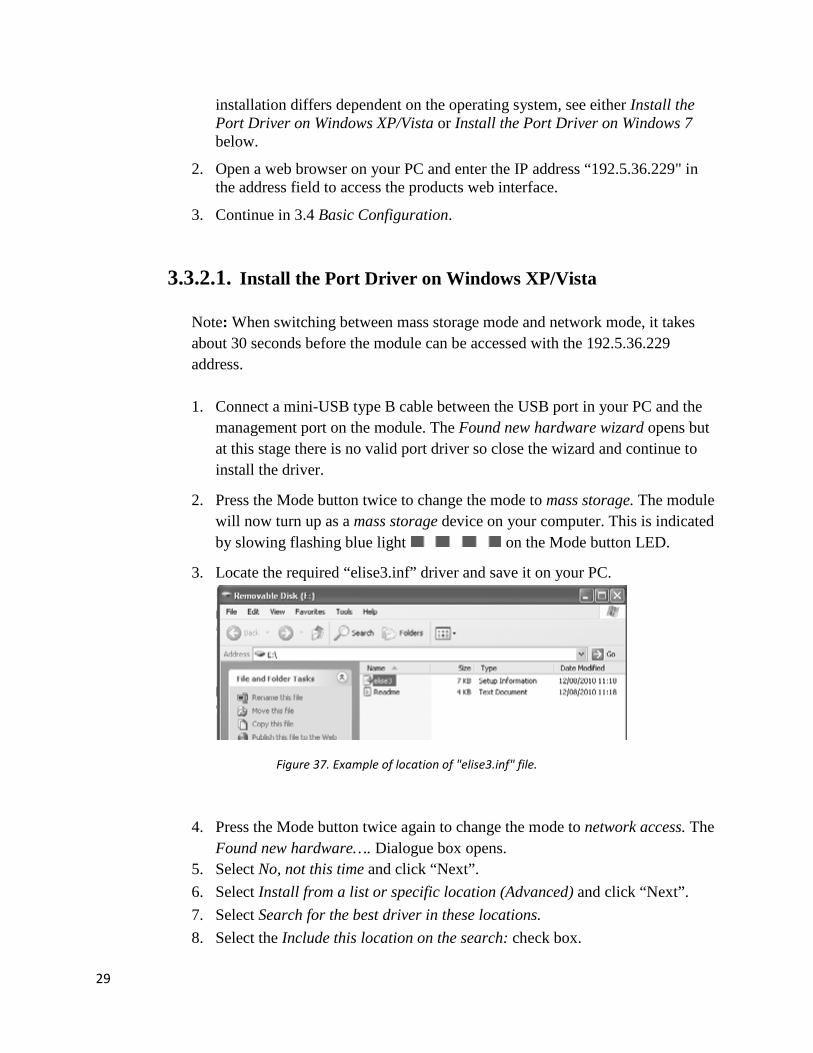
3. Locate the required “elise3.inf” driver and save it on your PC.
Figure 37. Example of location of "elise3.inf" file.
4. Press the Mode button twice again to change the mode to network access. The Found new hardware…. Dialogue box opens.
5. Select No, not this time and click “Next”. 6. Select Install from a list or specific location (Advanced) and click “Next”. 7. Select Search for the best driver in these locations. 8. Select the Include this location on the search: check box.

30
9. Browse to the folder where the port driver is saved.
Figure 38. Browse to folder where the port driver is saved.
10. Click “Next”. The installation of the port driver begins. If a message opens,
saying the software has not passed Windows Logo testing, click “Continue Anyway”.
11. Click “Finish”. A dialogue box will open and inform you that new hardware is installed.
3.3.2.2. Install the Port Driver on Windows 7 Note: When switching between mass storage mode and network mode, it takes about 30 seconds before the module can be accessed with the 192.5.36.229 address.
1. Connect a mini-USB type B cable between the USB port on your PC and the
management port on the module.
2. Press the Mode button twice to change the mode to mass storage. The module will now turn up as a mass storage device on your computer. This is indicated by slow flashing blue light on the Mode button LED.
3. Locate the required “elise3.inf” driver and save it on your PC.
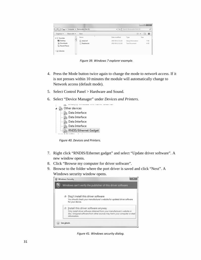
31
Figure 39. Windows 7 explorer example.
4. Press the Mode button twice again to change the mode to network access. If it
is not presses within 10 minutes the module will automatically change to Network access (default mode).
5. Select Control Panel > Hardware and Sound.
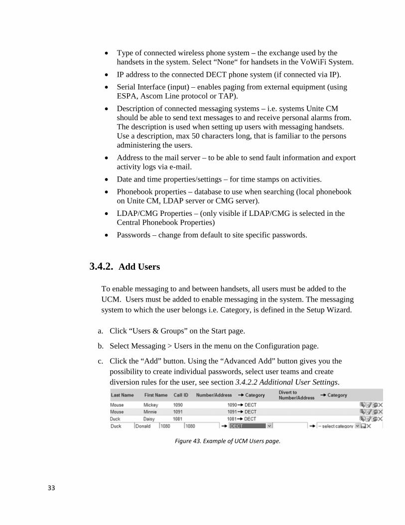
6. Select “Device Manager” under Devices and Printers.
Figure 40. Devices and Printers.
7. Right click “RNDIS/Ethernet gadget” and select “Update driver software”. A
new window opens. 8. Click “Browse my computer for driver software”. 9. Browse to the folder where the port driver is saved and click “Next”. A
Windows security window opens.
Figure 41. Windows security dialog.

32
10. Click “Install this driver software anyway”. The installation of the port driver
begins.
11. Click “Close” when the installation has finished. The port driver “Linux USB Ethernet/RNDIS Gadget” is now installed in Control > Panel > Hardware and Sound > Device and Printers > Device manager > Network adapters.
Figure 42. Network Adapters
3.4. Basic Configuration The Elise3 needs to be configured with basic settings. Some of the products settings can be set in an installation Setup Wizard accessible from the web interface. The Setup Wizard will start automatically the first time the module is accessed from the web browser and every time until the configuration has been saved. Follow the wizard and fill in the required data (IP address, NTP server, license etc.). After it has been saved the wizard can always be opened from the start page. Other settings are set from the application’s configuration pages and are described in the application’s Installation and Operation Manual (TD 92735EN). The first time and as long as Unite CM is not configured, the setup wizard will start automatically when logging on from a web browser. It requires an “admin” or “sysadmin” password. The content of the wizard is depending on the license. It means that all configuration is not shown for all licenses.
3.4.1. Log on to UCM
The setup wizard will open and help you with the basic configuration. The setup wizard includes the following settings:
• Network setup – can be set manually or via DHCP. • License number – the type of license determines the functionality.
33
• Type of connected wireless phone system – the exchange used by the handsets in the system. Select “None“ for handsets in the VoWiFi System.
• IP address to the connected DECT phone system (if connected via IP). • Serial Interface (input) – enables paging from external equipment (using
ESPA, Ascom Line protocol or TAP). • Description of connected messaging systems – i.e. systems Unite CM
should be able to send text messages to and receive personal alarms from. The description is used when setting up users with messaging handsets. Use a description, max 50 characters long, that is familiar to the persons administering the users.
• Address to the mail server – to be able to send fault information and export activity logs via e-mail.
• Date and time properties/settings – for time stamps on activities. • Phonebook properties – database to use when searching (local phonebook
on Unite CM, LDAP server or CMG server). • LDAP/CMG Properties – (only visible if LDAP/CMG is selected in the
Central Phonebook Properties) • Passwords – change from default to site specific passwords.
3.4.2. Add Users To enable messaging to and between handsets, all users must be added to the UCM. Users must be added to enable messaging in the system. The messaging system to which the user belongs i.e. Category, is defined in the Setup Wizard.
a. Click “Users & Groups” on the Start page.
b. Select Messaging > Users in the menu on the Configuration page.
c. Click the “Add” button. Using the “Advanced Add” button gives you the
possibility to create individual passwords, select user teams and create diversion rules for the user, see section 3.4.2.2 Additional User Settings.
Figure 43. Example of UCM Users page.
34
d. Enter the following settings:
Setting Description
Last Name: The family name
First Name The first (given) name
Call ID: The Call ID can be numerical or a text string (max 50 characters). Normally the Call ID is set as the same as the handset phone number.
Number/Address: The phone number or the personal address within selected category.
Category: This is the messaging system to which the handset belongs, (defined in the Setup Wizard). Updating or adding messaging systems is done in Messaging > Categories.
Divert to Number/Address: The number/address to divert the message to if the Call ID is not reachable (delivery failure, absent or out of range). This is the primary destination for diverted messages.
e. Click the symbol to save the added user only. Use the “Save” button to
save all users if several have been added.
3.4.2.1. Import Users From a CSV File
A CSV file template with instructions on how to add user information, is included in Unite CM. Obtain the template and read the instructions carefully since the user information must be added in the right order.
Obtain the CSV template.
1. Click “Users & Groups” on the start page. 2. Select Messaging > Import in the menu on the Configuration page

35
Figure 44. Import Users file dialog.
3. Select character to use as separator in the template. 4. Click the “Import Template” link and save the file. 5. Open the CSV file and read the instructions. 6. Add users and save the file.
Import the users
7. Click “Browse” to locate the CSV file. 8. Click “Import”.
Note that user information in the CSV file only adds new users to Unite CM, it does not support editing of existing users. If user information in Unite CM needs to be edited, it must be done manually in the user interface.
3.4.2.2. Additional User Settings
Additional user settings are set on the User Setup page. This page is reached by clicking the symbol to the right of an existing user, or by clicking the “Advanced Add” button for a new user.
a. Click “Users & Groups” on the start page.
b. Select Messaging > Users in the menu on the Configuration page.
c. Open the User Setup page by clicking the symbol to the right of an
existing user, or by clicking the “Advanced Add” button for a new user.
d. Enter/Edit the following settings :

36
User Setup
First Name: The first (given) name.
Last Name: The family name.
Title: The users title or function on the site.
Call ID
Call ID: The Call ID can be numerical or a text string (max 50 characters). Normally the Call ID is set as the same as the handset phone number. This Call ID is normally used when sending message to this user from for example NetPage.
Number/Address: The phone number or the personal address within selected category.
Category: This is the messaging system to which the handset belongs, (defined in the Setup Wizard). Updating or adding messaging systems is done in Messaging > Categories.
User Account
User ID: A user can be given an individual User ID for logging in to the messaging system and for administration of duty assignments.
Password: Password used for the above UserID.
User Teams
Available: Teams available to the user.
Member of: Teams that this user is a member of.
Diversion
Divert to Number/Address:
Enter a number or a personal address to divert messages to.

37
Interface: The messaging system to which the handset belongs, (defined in the Setup Wizard).
3.4.3. Groups
Note: It is recommended to use local groups (groups created in the MSS) in order to get the best performance from the MSS functionality.
Groups makes it possible to send one message to several handsets. Groups for the complete system are administrated in one place. The overview page gives a list of all group numbers that exist in the system. Groups make it possible to send one message to several handsets in the system.
Figure 45. Example of Groups configuration page.
Three different kind of group IDs can be set up: 1) Group ID
Each member in this group will receive a separate message, which means that if it is a large group it will take some time before the message has reached all members. Used for small groups (up to 10 members) and groups where delivery control is needed.
2) Multicast Group ID
In a Multicast Group one message is sent to a group number in a specified category, which means that the message is sent simultaneously to all members in the group. Used for large groups with no need of delivery control.
3) Broadcast ID

38
In a Broadcast Group one message is sent to all handsets in the specified category. Used for sending general messages to all members.
Note: This guide will only focus on the Single Group (Group ID). See “UCM Installation and Operation Manual TD 92735EN” for details on Multicast Group ID and Broadcast ID .
The Call IDs included in a group have to exist as individual Call IDs in the Number Plan. If they do not exist in the Number Plan, an error message (with the missing Call IDs) is displayed when trying to save the group. The Call IDs must be added before the group can be saved.
3.4.3.1. Create a Single Group
a. Click “Users & Groups” on the start page. b. Select Messaging > Groups in the menu on the Configuration page. c. Click “Group ID”.
Figure 46. Example of creating a single group.

39
d. Enter the following settings:
Setting Description
Call ID: Call ID for the Group
Description: Description for the group
Diversion permitted for included members:
Yes - Group messages will be delivered as any other messages. No - No diversion will be made for group messages
3.4.3.2. Add Members to a Group Add handsets to the group in the Member Administration section, either by:
a) adding members by one b) search for members to add.
NOTE: The Call IDs must have been defined in Messaging > Users, if not, the group cannot be saved.
A) Adding members one by one:
1. Click the “Add Member” button and enter the first Call ID. 2. Select if you want the next row to be “Empty” (default), to “copy
previous” Call ID or “increment previous” Call ID by choosing an option button.
3. Click “Add Member”. 4. Enter the next Call ID
B) Search for members to add:
1. Click the “Call ID Search” button. 2. Enter the first number(s) in the Call ID or Number/Address field, followed
by the wildcard “*”. The fields can also remain empty and only category selected. Then all Call IDs in that category will be shown.
3. Click “Search”. A list with matching Call IDs will be displayed. 4. Select users by clicking the “Add” button. 5. Close the UNS search list.
40
3.4.4. Backup the Configuration The complete configuration for the current software on the module is included in the backup. Files that have been added or changed on the ftp-area are also included in the backup. The backup file is saved in a proprietary file format and cannot be edited. Save it in a place where you can easily find it for a restore.
1. Click “Configuration” on the start page. 2. Select Other > Backup/Restore on the Configuration page. 3. Click the “Backup” button. 4. Click the “Save” button in the opened dialogue. 5. Select a location and enter a file name, then save the file.
Note: Saving file can take several minutes if configuration contains many files, for instance if may software files and devices have been added to device management.
3.4.5. Restore the Configuration NOTE: When Unite CM is restored, all changes that have been made since the last backup will be discarded.
1. Click “Configuration” on the start page. 2. Select Other > Backup/Restore on the Configuration page. 3. Click “Browse” button and select the backup file. 4. Click the “Restore” button.
The text “Backup successfully restored!“ will be displayed and inform you when the restore is ready. Restoring can take several minutes if backup file is large, for instance if many software files and devices is included in backup.
5. Click the “Restart Now” or the “Restart Later” button. If the IP address
or DECT interface has been changed the module needs to be restarted for the settings to take effect.
A restart will take a couple of minutes and during that time Unite CM is unreachable. When the restart is completed, the window will refresh to the Configuration page overview.

41
4. Configure the UCM for MSS The UCM needs to be configured so Mobile Data and Alarms are sent to the MSS application. Go to the UCM Advanced Configuration page. If you are using DECT handsets you will need to go to Message Distribution under the DECT Interface section. If you are using WiFi handsets then you will need to go to Message Distribution under the WLAN Interface section. You will need to set the destination for Mobile Data and Alarms. Below are screenshots for DECT Message Distribution. If you are setting the destination for an MSS installation on the same UCM that you are currently logged into then the destination would be “127.0.0.1/OAJ”. If the installation is on a different UCM, the destination would be the IP Address of the UCM followed by “/OAJ”.
Figure 47. Message Distribution - Mobile Data.

42
Figure 48. Message Distribution – Alarms.
5. MSS Installation
New installations of the MSS are completed at the UCM Configuration page. Select the “Other” tab and then select the “Backup/Restore” link. Browse and select the MSS installation file. Click on the “Restore” button to start the installation process. When the installation has completed, click on the “Restart” button to prompt the system to restart.
6. Upgrading the MSS Application The MSS makes it easy to upgrade to a newer version. Go to the Start Page and select the “Advanced Admin” button. Select the “Upgrade” button on the left. Browse and select the MSS upgrade installation file. Click the Submit button to start the upgrade process. When the upgrade has completed, click on the “Restart Application” link to prompt the application to restart. You can check the version number by clicking on the “About” button on the Start Page (version number will be in the upper left corner).

43
7. Backup/Restore MSS Database The MSS provides the ability to backup and restore the database used by the application. Go to the Start Page and select the “Advanced Admin” button. When the page loads you should see the “Backup/Restore Database” page (if not, click on the “Backup/Restore” button). The “Backup” button will back up the MSS database to a file named “data.ZIP”. To restore the MSS database, browse and select the database file. When restore has completed, click on the “Restart Application” link to prompt the application to restart.
8. Handset Configuration This section will cover defining items in the handset Services Menu that will send requests to the MSS application. First, we will cover the basics on creating a Service and then go through creating Services for the default options that ship with the MSS. 8.1. How to Create a Service
1. Select "Services". 2. Select the service (1 - 10) to be configured. 3. In the Name field, enter the name of the service. It will be displayed in the handset. 4. In the Type drop-down list, select the function to be used. For sending request to the
MSS we will be using “Data Send” and “Data with Prefix”. 5. If needed, in the Prefix field, enter the prefix to be used.
8.2. How to Delete a Service
1. Select “Services”. 2. Select the service to be deleted. 3. In the Name field, delete the name of the service.
8.3. Adding Predefined MSS Services
All of the MSS Services will require a value to be added to the Prefix field. It is important that the value in this field match the Mobile Data Prefix value of the MSS option that you will be trying to request. Below is a list of all the data needed to create the shipped options.
44
8.3.1. Reminders
a. REMINDER: Pain Assessment o Function: Data Send o Prefix: “RPA:” o Send Data: None
b. REMINDER: Pain Meds o Function: Data Send o Prefix: “RPM:” o Send Data: None
c. REMINDER: Rotate Patient
o Function: Data Send o Prefix: “RRP:” o Send Data: None
d. REMINDER: General o Function: Data Send o Prefix: “RG:” o Send Data: None
e. Reminder Lookup o Function: Data Send o Prefix: “RL:” o Send Data: None
8.3.2. Assist Request a. Lift Help
o Function: Data Send o Prefix: “LH:” o Send Data: None
b. Bariatric Lift Help
o Function: Data Send o Prefix: “BLH:” o Send Data: None

45
c. Need Assistance o Function: Data Send o Prefix: “NA:” o Send Data: None
d. Pain Meds
o Function: Data Send o Prefix: “PM:” o Send Data: None
e. Cancel
o Function: Data Send o Prefix: “CANCEL” o Send Data: None
8.3.3. Conference Request
a. ADULT Conference Request o Function: Data Send o Prefix: “AD:” o Send Data: None
b. ER Conference Request o Function: Data Send o Prefix: “ER:” o Send Data: None
c. OB Conference Request o Function: Data Send o Prefix: “OB:” o Send Data: None
d. PEDS Conference Request o Function: Data Send o Prefix: “PD:” o Send Data: None
e. STORK Conference Request o Function: Data Send
46
o Prefix: “ST:” o Send Data: None
9. MSS Configuration
To configure the MSS application go to the Start Page and click on the “MSS Configuration” button. Links to the configuration pages are listed on the left.
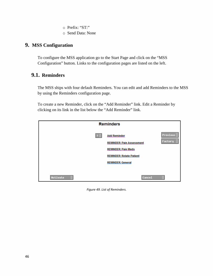
9.1. Reminders The MSS ships with four default Reminders. You can edit and add Reminders to the MSS by using the Reminders configuration page. To create a new Reminder, click on the “Add Reminder” link. Edit a Reminder by clicking on its link in the list below the “Add Reminder” link.
Figure 49. List of Reminders.

47
Figure 50. Reminders Configuration page.
This table contains descriptions of all the Reminder Configuration parameters .
Setting Description
Name: Assign a name to the Reminder.
Mobile Data Prefix: The alphanumeric characters used as the Data Prefix value when creating a Service on the handset. Note: The value you assign to "Mobile Data Prefix” must match the Data Prefix value of the handset Services Menu item that will be used to create the Reminder.
Reminder Text: Text that will be displayed on the handset for the Reminder. The location of the Reminder will be appended to the end of

48
the text.
Reminder Confirm: If set to 'True' the handset will receive follow up Reminder messages until the 'Accept' soft key has been selected or the Reminder has expired.
Delete After Timeout: The Reminder will timeout after a set interval of minutes. If this parameter is set to 'True' then the Reminder will be deleted from the handset after the Timeout interval has expired. If set to 'False' the Reminder will remain on the handset after the Timeout interval has expired. The timeout interval is set on the Reminder Global Timers page.
Interval Snooze: Turn the Interval Snooze feature on or off for the Reminder. Interval Snooze provides defined reminder intervals to the user which can delay a reminder for the set time period.
Beep Code: The number of beeps a message will indicate when arriving on the handset.
Intensity: Sets the intensity of the message's indication. This parameter may determine the sound volume, vibration, etc.
Priority Level: Sets the priority level of a message.
Color: Sets the color indication of a message.
Delete Reminder: Click link to automatically delete this Reminder from the Mobile Services Suite.
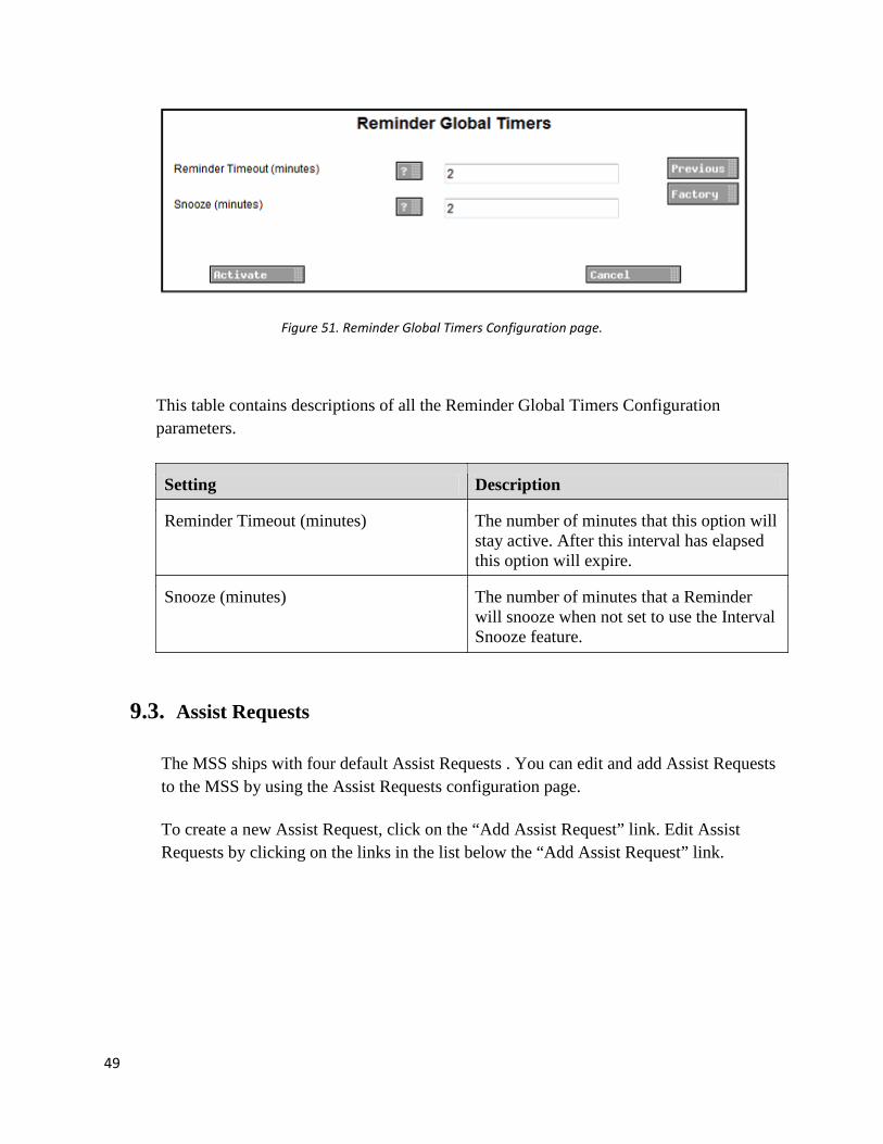
9.2. Reminder Global Timers This configuration page allows you to adjust the number of minutes that a Reminder is active before it times out and the default number of minutes that a Reminder can snooze. This is a screen shot of the configuration page. The table below contains descriptions of all the parameters.
49
Figure 51. Reminder Global Timers Configuration page.
This table contains descriptions of all the Reminder Global Timers Configuration parameters.
Setting Description
Reminder Timeout (minutes) The number of minutes that this option will stay active. After this interval has elapsed this option will expire.
Snooze (minutes) The number of minutes that a Reminder will snooze when not set to use the Interval Snooze feature.
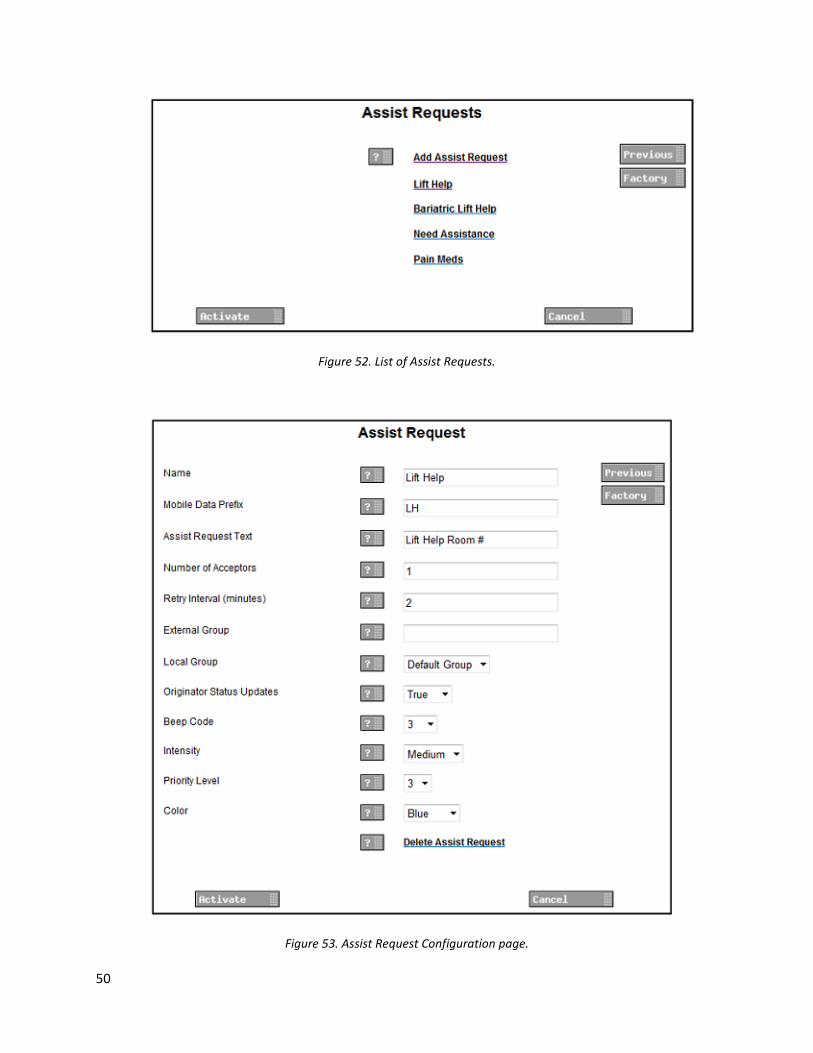
9.3. Assist Requests The MSS ships with four default Assist Requests . You can edit and add Assist Requests to the MSS by using the Assist Requests configuration page. To create a new Assist Request, click on the “Add Assist Request” link. Edit Assist Requests by clicking on the links in the list below the “Add Assist Request” link.
50
Figure 52. List of Assist Requests.
Figure 53. Assist Request Configuration page.

51
This table contains descriptions of all the Assist Request Configuration parameters.
Setting Description
Name: Assign a name to the Assist Request.
Mobile Data Prefix: The alphanumeric characters used as the Data Prefix value when creating a Service on the handset. Note: Make sure the value you assign to “Mobile Data Prefix” matches the Data Prefix value of the handset’s Services Menu item that will be used to create an Assist Request.
Assist Request Text: Text that will be displayed on the handset for the Assist Request. The location will be appended to the end of the text.
Number of Acceptors: The number of handsets required to accept an Assist Request.
Retry Interval (minutes):
The number of minutes between sending retry messages to handsets that have not yet accepted an Assist Request.
External Group: The call id of the UCM Group that will be receiving the Assist Request.
Local Group: The name of the Mobile Services Suite Group that will be receiving the Assist Request.
Originator Status Updates:
The Mobile Services Suite will send update messages to the Originator and Recipients of the Acceptance status of the Assist Request.
Beep Code: The number of beeps a message will indicate when arriving on the handset.
Intensity: Sets the intensity of the message’s indication. This parameter may determine the sound volume, vibration, etc.
Priority Level: Sets the priority level of a message.
Color: Sets the color indication of a message.
Delete Assist Request: Click on link to automatically delete this Assist Request from the Mobile Services Suite.

52
9.4. Assist Request Global Timer This configuration page allows you to adjust number of minutes that an Assist Request is active before it times out.
Figure 54. Assist Request Global Timer.
Setting Description
Assist Request Timeout (minutes) The number of minutes that this option will stay active. After this interval has elapsed the option will expire.

53
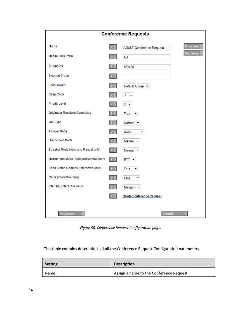
9.5. Conference Requests The MSS ships with five default Conference Requests. You can edit and add Conference Requests to the MSS by using the Conference Requests configuration page. To create a new Conference Request, click on the “Add Conference Request” link. Edit a Conference Requests by clicking on its link in the list below the “Add Conference Request” link.
Figure 55. List of Conference Requests.
54
Figure 56. Conference Request Configuration page.
This table contains descriptions of all the Conference Request Configuration parameters.
Setting Description
Name: Assign a name to the Conference Request
55
Mobile Data Prefix: The alphanumeric characters used as the Data Prefix value when creating a Service on the handset. Note: Make sure the value you assign to “Mobile Data Prefix” matches the Data Prefix value of the handset’s Services Menu item that will be used to create an Assist Request.
Bridge DN: The number of the Conference Bridge providing the conference room for this request.
External Group: The call id of the UCM Group that will be receiving the request.
Local Group: The name of the Mobile Services Suite Group that will be receiving the request.
Beep Code: The number of beeps a message will indicate when arriving on the handset.
Priority Level: Sets the priority level of a message.
Originator Receives Same Msg: The originator of the Conference Request will receive the same type of message as the recipients.
Call Type: Defines the type of call that should be set up. The Normal setting will set up a normal call with duplex speech. Please note that Microphone Mode’s “PTT” option will override the functionality of this setting. The PTT setting will set up a simplex voice call supporting PTT (Push To Talk). Please note that this setting is only used when the Microphone Mode is set to “PTT”. Note: When Call Type is set to “PTT” the d62 DECT handset is not able to join a Conference call. This is not an issue for the i62 Wi-Fi handset.
Answer Mode: Defines how the call will be answered by the receiving device. The Auto setting allows the handset to answer the call automatically. The Interactive setting sends a message to the handset that will allow the user to join a call by selecting the “Join” soft key. The Manual setting allows the user to answer a call by selecting the “Accept” soft key.
Disconnect Mode: Defines how the conference call shall be disconnected. The Manual setting requires each user to hang up manually. The Auto setting defines that the conference call is disconnected automatically for all handsets when the originator hands up. Currently, Disconnect Mode has no effect in how the call is disconnected but may be
56
fully implemented in a future version of the UCM. You can however define this functionality in the Conference Bridge. When the option “Close conference when last marked user exists” is checked, the call is automatically closed when the marked user (originator of the call) hangs up. When this option is not checked, each user has to hang up to exit the conference call.
Speaker Mode (Auto and Manual only):
Defines how the speaker in the receiving device shall operate during the call. The Off setting will turn off both the speaker and earpiece. The Normal setting will turn on the earpiece only. The Loud setting will turn on the speaker only. Note: the d62 DECT handset does not provide the option to change from speaker or earpiece mode to another mode once set by a Conference Request message. This is not an issue for the i62 Wi-Fi handset.
Microphone Mode (Auto and Manual only):
Defines how the microphone on the receiving device shall operate during the call. The setting PTT means that a button must be pressed when talking. The “On” setting defines that the microphone will be on during the call. Please note, the Microphone Mode only works when Answer Mode is set to “Auto” or “Manual” mode.
Send Status (Interactive only): Allows the Mobile Services Suite to monitor the Conference Request. The originator of the Conference Request will receive an update message after a handset has joined the call. The setting is only applicable to handsets that receive a message with Answer Mode set to “Interactive”
Color (Interactive only): Sets the color indication of a message.
Intensity (Interactive only): Sets the intensity of the message’s indication. This parameter may determine the sound volume, vibration, etc.
Originator Settings Set the parameters for the message that will be sent to the originator of the Conference Request.
Delete Conference Request: Click link to automatically delete this Conference Request from the Mobile Services Suite.
57
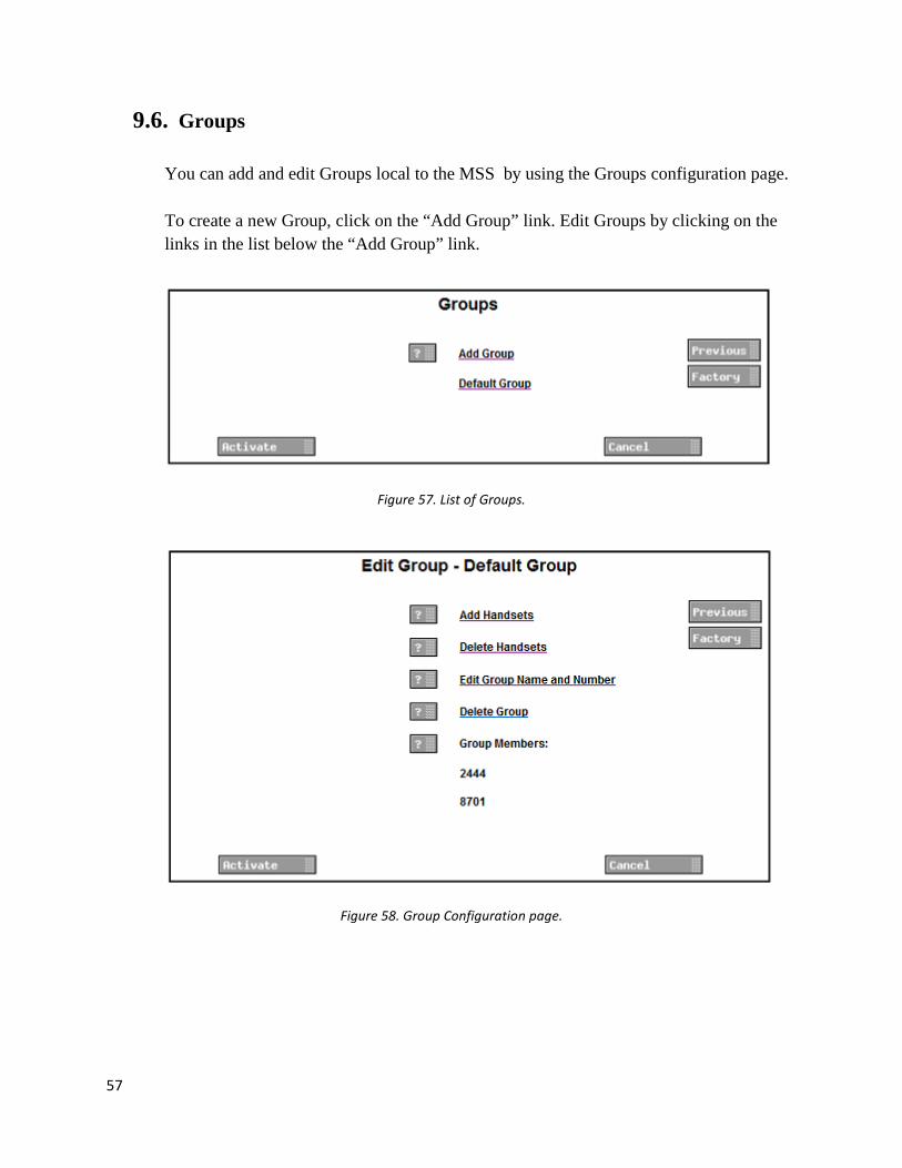
9.6. Groups You can add and edit Groups local to the MSS by using the Groups configuration page. To create a new Group, click on the “Add Group” link. Edit Groups by clicking on the links in the list below the “Add Group” link.
Figure 57. List of Groups.
Figure 58. Group Configuration page.

58
This table contains descriptions of all the Group Configuration parameters.
Setting Description
Group Name: Name of the group.
Group Number: Call ID of the group.
Add Handsets: Loads page for adding handsets to the Group.
Delete Handsets: Loads page for deleting handsets from this Group.
Delete Group: Click link to automatically delete the Group from the Mobile Services Suite.
Group Members: List if handsets that are members of the Group.
9.7. Alarm Block The Alarm Block configuration page allows for Assist Requests and Conference Requests to be assigned to the two Push Button alarms. Location is required for alarms assigned an Assist Request.
Figure 59. Alarm Block Configuration page.
Setting Description
Push Button Alarm 1 Assign an Assist Request or Conference Request to
59
the alarm.
Alarm 1 Location Assign a location to the alarm. Required for Assist Requests.
Push Button Alarm 2 Assign an Assist Request or Conference Request to the Alarm.
Alarm 2 Location Assign a location to the alarm. Required for Assist Requests.
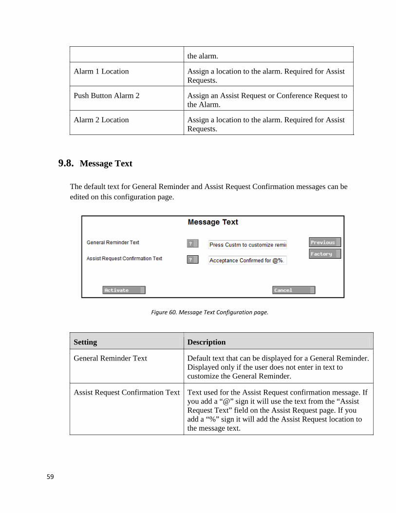
9.8. Message Text The default text for General Reminder and Assist Request Confirmation messages can be edited on this configuration page.
Figure 60. Message Text Configuration page.
Setting Description
General Reminder Text Default text that can be displayed for a General Reminder. Displayed only if the user does not enter in text to customize the General Reminder.
Assist Request Confirmation Text Text used for the Assist Request confirmation message. If you add a “@” sign it will use the text from the “Assist Request Text” field on the Assist Request page. If you add a “%” sign it will add the Assist Request location to the message text.
60
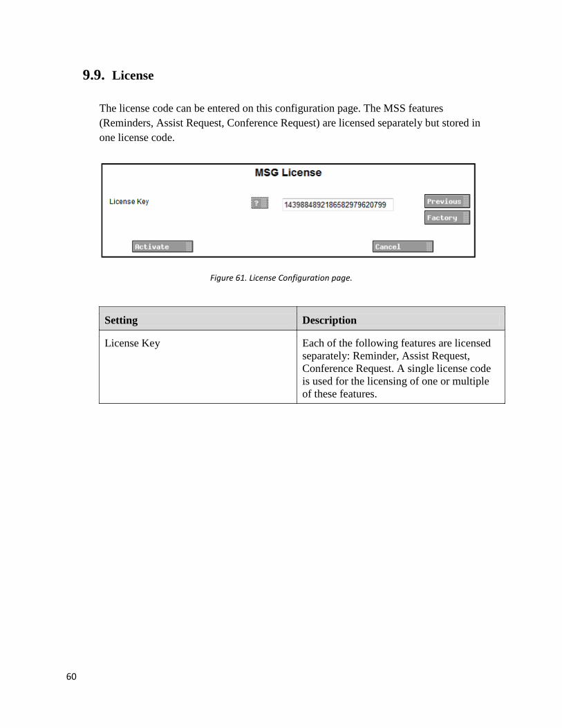
9.9. License The license code can be entered on this configuration page. The MSS features (Reminders, Assist Request, Conference Request) are licensed separately but stored in one license code.
Figure 61. License Configuration page.
Setting Description
License Key Each of the following features are licensed separately: Reminder, Assist Request, Conference Request. A single license code is used for the licensing of one or multiple of these features.