Embed Size (px)
Citation preview
NEO-DYN
MODELS 122P, 123P, 130P, 131P, 132P, 181P, 231P, 232P
ADJUSTABLE PRESSURE SWITCHES;
MODEL 125P AND 225P
FACTORY SET PRESSURE SWITCHES;
ENCLOSURE 6N FOR EXPLOSIVE ATMOSPHERES
INSTALLATION AND
OPERATION MANUAL
PN 610-0009 Rev K
Enclosure 6N Pressure Switches Page i
Manual No. 610-0009 REV K
Neo-Dyn®
28150 Industry Drive
Valencia, CA 91355
Tel: (661) 295-4000
Fax: (661) 294-1750
World Wide Web: www.neodyn.com
©Copyright 2002
ITT Industries
Important Information
The product warranty applicable to this ITT Neo-Dyn® instrument is as stated on the last page
of this manual.
Should any after-delivery problems arise, please contact ITT Neo-Dyn’s Customer Service
using the information above. Our normal business hours are weekdays, 7:00 am to 3:30 PM,
Pacific Time.
Before installing this Pressure Switch, become familiar with the installation and adjustment
instructions in Chapters 2 and 3
WARNING Indicates a hazard which can cause severe personal injury, death, or substantial
property damage if the warning is ignored.
CAUTION Indicates a hazard which will or can cause minor personal injury or property damage if the
caution is ignored.
SPECIAL CONDITIONS
FOR SAFE USE
The electrical snap switch assemblies shall be installed such that the equipment wiring is
protected from mechanical damage by the use of metal conduit or a method providing
equivalent protection. The equipment wiring must not be subjected to tension or torque. If it is
to be terminated within a potentially explosive atmosphere, a suitably certified termination
facility must be used.
NOTE Indicates additional information about a particular item necessary to the operation of the unit.
This document contains proprietary information, which is the property of Neo-Dyn®, a unit of
ITT industries. This document may not be reproduced, either in part or in full, without the
consent of ITT industries.
Enclosure 6N Pressure Switches Page ii
TABLE OF CONTENTS
CHAPTER 1 INTRODUCTION ............................................................................................................ 1
CUSTOMER SERVICE .................................................................................................................... 2
OTHER CONFIGURATIONS .......................................................................................................... 2
CHAPTER 2 INSTALLATION ............................................................................................................. 3
MOUNTING ..................................................................................................................................... 3
PROCESS CONNECTIONS ............................................................................................................. 4
PROCESS MEDIA ............................................................................................................................ 4
POTENTIALLY EXPLOSIVE ATMOSPHERES (HAZARDOUS LOCATIONS) ...................... 5
ELECTRICAL CONNECTIONS...................................................................................................... 5
CHAPTER 3 ADJUSTMENTS AFTER INSTALLATION .................................................................. 6
SETPOINT ADJUSTMENT ............................................................................................................. 6
CHAPTER 4 TROUBLESHOOTING ................................................................................................... 8
CHAPTER 5 SPECIFICATIONS .......................................................................................................... 9
WARRANTY INFORMATION .......................................................................................................... 16
Enclosure 6N Pressure Switches Page 1
CHAPTER
1
INTRODUCTION
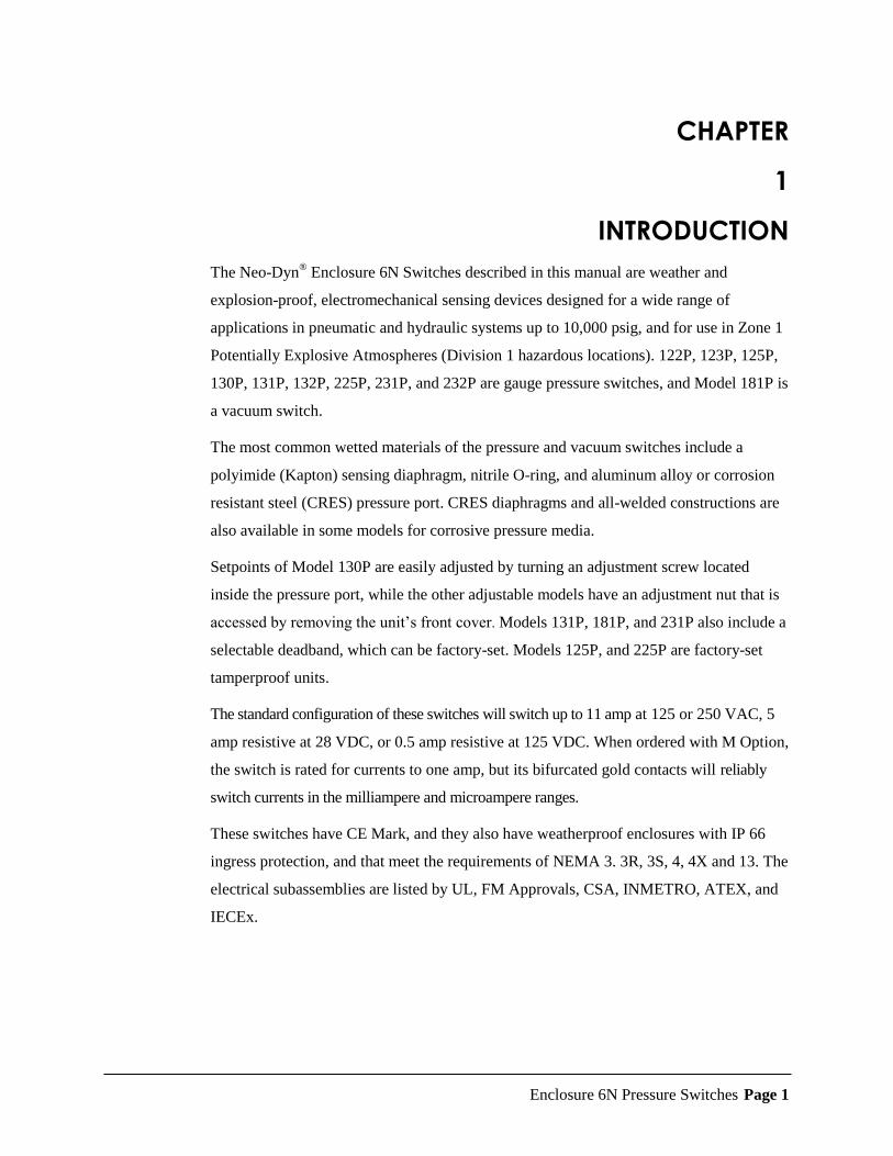
The Neo-Dyn® Enclosure 6N Switches described in this manual are weather and
explosion-proof, electromechanical sensing devices designed for a wide range of
applications in pneumatic and hydraulic systems up to 10,000 psig, and for use in Zone 1
Potentially Explosive Atmospheres (Division 1 hazardous locations). 122P, 123P, 125P,
130P, 131P, 132P, 225P, 231P, and 232P are gauge pressure switches, and Model 181P is
a vacuum switch.
The most common wetted materials of the pressure and vacuum switches include a
polyimide (Kapton) sensing diaphragm, nitrile O-ring, and aluminum alloy or corrosion
resistant steel (CRES) pressure port. CRES diaphragms and all-welded constructions are
also available in some models for corrosive pressure media.
Setpoints of Model 130P are easily adjusted by turning an adjustment screw located
inside the pressure port, while the other adjustable models have an adjustment nut that is
accessed by removing the unit’s front cover. Models 131P, 181P, and 231P also include a
selectable deadband, which can be factory-set. Models 125P, and 225P are factory-set
tamperproof units.
The standard configuration of these switches will switch up to 11 amp at 125 or 250 VAC, 5
amp resistive at 28 VDC, or 0.5 amp resistive at 125 VDC. When ordered with M Option,
the switch is rated for currents to one amp, but its bifurcated gold contacts will reliably
switch currents in the milliampere and microampere ranges.
These switches have CE Mark, and they also have weatherproof enclosures with IP 66
ingress protection, and that meet the requirements of NEMA 3. 3R, 3S, 4, 4X and 13. The
electrical subassemblies are listed by UL, FM Approvals, CSA, INMETRO, ATEX, and
IECEx.
Enclosure 6N Pressure Switches Page 2
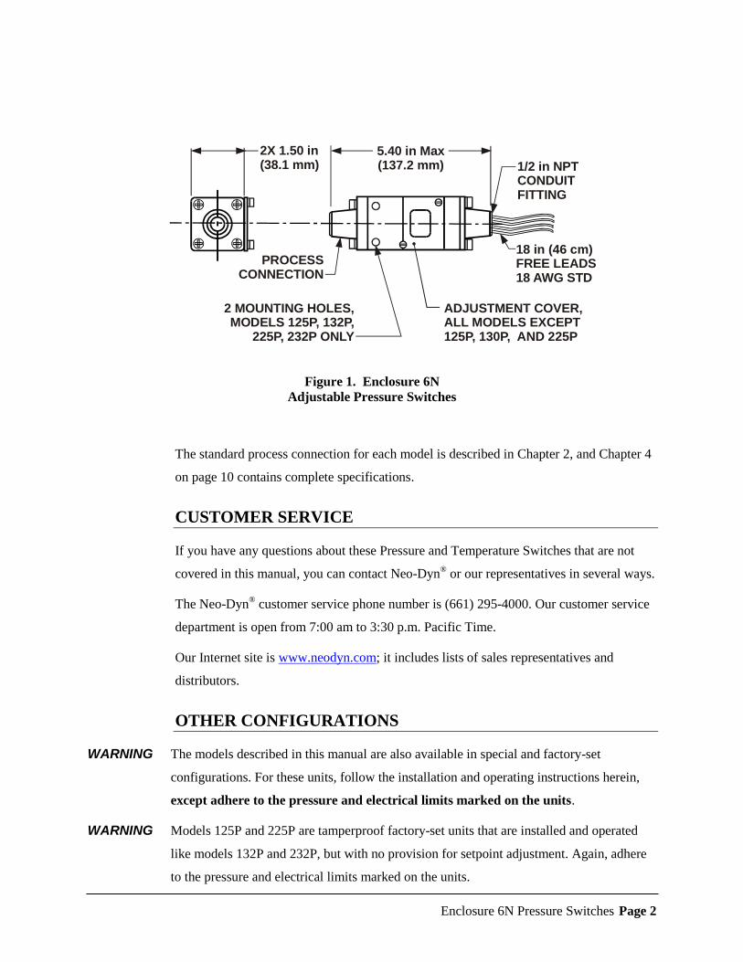
Figure 1. Enclosure 6N
Adjustable Pressure Switches
The standard process connection for each model is described in Chapter 2, and Chapter 4
on page 10 contains complete specifications.
CUSTOMER SERVICE
If you have any questions about these Pressure and Temperature Switches that are not
covered in this manual, you can contact Neo-Dyn® or our representatives in several ways.
The Neo-Dyn® customer service phone number is (661) 295-4000. Our customer service
department is open from 7:00 am to 3:30 p.m. Pacific Time.
Our Internet site is www.neodyn.com; it includes lists of sales representatives and
distributors.
OTHER CONFIGURATIONS
WARNING The models described in this manual are also available in special and factory-set
configurations. For these units, follow the installation and operating instructions herein,
except adhere to the pressure and electrical limits marked on the units.
WARNING Models 125P and 225P are tamperproof factory-set units that are installed and operated
like models 132P and 232P, but with no provision for setpoint adjustment. Again, adhere
to the pressure and electrical limits marked on the units.
PROCESSCONNECTION
2 MOUNTING HOLES,MODELS 125P, 132P,
225P, 232P ONLY
ADJUSTMENT COVER,ALL MODELS EXCEPT125P, 130P, AND 225P
1/2 in NPTCONDUITFITTING
18 in (46 cm)FREE LEADS18 AWG STD
5.40 in Max(137.2 mm)
2X 1.50 in(38.1 mm)
Enclosure 6N Pressure Switches Page 3
CHAPTER
2
INSTALLATION
Installation of these Neo-Dyn® Enclosure 6N pressure switches is straightforward.
However, they must be installed by a qualified electrician, in compliance with all local
and national electrical codes.
WARNING Electrical hazard
WARNING Do not make electrical connections while power is on.
WARNING Always check for multiple circuits.
WARNING Always make sure grounding is adequate.
WARNING Do not remove switch while under pressure.
MOUNTING
The pressure switch can be mounted directly to the process connection if there is no
significant vibration and the fluid lines are capable of supporting the weight; in addition,
Models 125P, 132P, 225P, and 232P can also be attached to a flat surface, such as a wall
or panel, using .190 in. diameter (no. 10) or M5 fasteners through the mounting holes that
are spaced 1.125 in. (28.6 mm) apart. The fastener length should include 1.50 inch (38.1
mm) above the mounting surface.
Enclosure 6N Pressure Switches Page 4
PROCESS CONNECTIONS
The process connections are:
Model 130P port: ¼” - 18 NPT male standard.
Model 131P, 181P, and 231P: combined ¼” - 18 NPT female and ½” - 14 NPT male
standard.
Models 132P and 232P: ¼” - 18 NPT female standard; ½ ” - 14 NPT female (G Option) and
7/16-20 SAE (E Option) are available.
Models 125P and 225P: ¼” - 18 NPT female standard
When installing the Pressure Switch, always:
Make sure that the unit and your system have matching threads.
Use the wrench flats provided.
Seal all joints with pipe joint sealing compound.
CAUTION Avoid excessive torque on all threaded connections.
WARNING Do not exceed the marked maximum operating pressure in normal operation.
The marked Proof Pressure is provided to give the maximum allowable pressure without
causing permanent damage to the pressure switch in the event of an over-pressure
condition. Set pressure relief/safety valves below this setting.
PROCESS MEDIA
Process media must be compatible with the wetted materials listed in Chapter 5 starting
on page 13. Compatibility is defined by an “A” rating in the Chemical Resistance Guide
for Metals and Alloys, the Chemical Resistance Guide for Plastics, and the Chemical
Resistance Guide for Elastomers, all published by Compass Publications, and available
from the National Association of Corrosion Engineers (NACE), Houston, Texas;
telephone 281 228 6200.
Enclosure 6N Pressure Switches Page 5
POTENTIALLY EXPLOSIVE ATMOSPHERES
(HAZARDOUS LOCATIONS)
Suitable for Zone 1, Ex db IIC explosive atmospheres, in accordance with Potentially
Explosive Atmospheres Directive 2014/68/EU (ATEX)
Suitable for Division 1; Class 1, Groups A, B, C and D; Class II, Groups E, F and G
hazardous locations, in accordance with the National Electric Code (NEC), and
applicable UL, CSA, FM, INMETRO specifications.
ELECTRICAL CONNECTIONS
18 AWG free leads 18 in (46 cm) long are standard, with a green wire grounded to the
case. 72 inch (183 cm) leads are available as R Option, and other lead lengths may be
ordered as special configurations. The leads are intended for installation in conduit
capable of withstanding possible explosion pressures, and the leads are factory sealed.
WARNING All field wiring must comply with requirements of the NEC or applicable local or
national electrical codes, including wire gauges and insulation temperature ratings.
Conduit seals may be required.
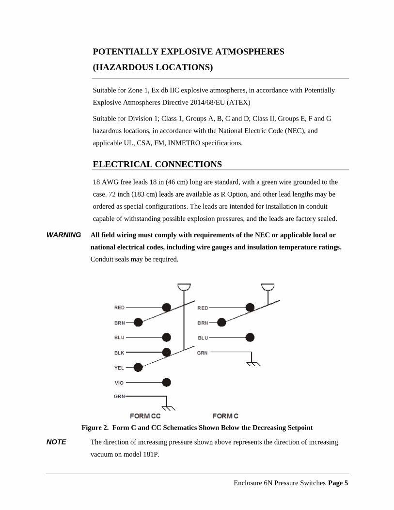
Figure 2. Form C and CC Schematics Shown Below the Decreasing Setpoint
NOTE The direction of increasing pressure shown above represents the direction of increasing
vacuum on model 181P.
Enclosure 6N Pressure Switches Page 6
CHAPTER
3
ADJUSTMENTS AFTER INSTALLATION
The factory-set setpoint or adjustable setpoint range is marked on the nameplate of the
switch. This section describes the adjustments needed after an Adjustable Pressure
Switch has been properly installed. Models 125P, and 225P are not adjustable.
SETPOINT ADJUSTMENT
WARNING Do not remove switch while under pressure.
1. Disconnect the electrical power. Check for multiple circuits.
2. On Model 130P, remove the pressure connection to allow access to the adjustment
nut inside the pressure port. On the other models, loosen the screws on the access
cover, and swing it to the side.
3. To change the setpoint on Model 130P, use an Allen wrench to rotate the adjustment
nut counterclockwise to increase the setpoint, and clockwise to decrease it. It takes
approximately 3 to 5 turns to move from one end of the adjustable range to the other
(the higher range units require more turns than the lower range units). Check the
setpoints per paragraphs 5 and 0 below for precise adjustments.
4. On the other models, the adjustment nut can be rotated by hand or with a small-
shafted screwdriver or similar tool inserted into a slot. The range scale is intended to
be used only as an approximate guide; it indicates the increasing setpoint on Models
122P, 123P, 132P, and 232P, and decreasing setpoint on Models 131P, 181P, and
231P.
5. To check the increasing setpoint, connect a pressure source and a calibrated pressure
gauge or transducer to the pressure port and slowly apply increasing pressure (or
vacuum on Model 181P) until the switch actuates. Actuation can be noted by
listening to the audible snap of the Belleville spring, or with an ohmmeter across the
appropriate free leads.
Enclosure 6N Pressure Switches Page 7
6. If you want to check the decreasing setpoint, slowly decrease the pressure or vacuum
after the switch has actuated and note the value at which the audible snap or an
ohmmeter indicates deactuation. Deadband may be calculated if desired by
subtracting the decreasing setpoint reading from the increasing setpoint reading.
7. On all models except 130P, replace the cover by swinging it back into position over
the adjustment window and tightening the screws until the cover is snug against its
gasket. Do not overtighten, as this could damage the gasket
Enclosure 6N Pressure Switches Page 8
CHAPTER
4
TROUBLESHOOTING
In-service problems are unlikely, but the following paragraphs suggest ways to verify any
problems that might arise:
1. Pressure Switch Leaks
If a leak is suspected, isolate the pressure switch from the rest of the system. Connect
the switch and a calibrated pressure gauge downstream from a pressure source and
shutoff valve. Apply normal system pressure, isolate the gauge and Pressure Switch
from the pressure source with the shutoff valve for at least one minute, and check for
leaks as evidenced by a drop in the gauge reading.
If a leak is verified, return the unit for repair. Contact ITT directly, or your local sales
representative or distributor (see www.neodyn.com for a contact list).
2. Failure to Switch
If application of pressure or vacuum 10% greater than the adjusted setpoint fails to
produce actuation, first check for contamination in the process connection, and verify
that the expected pressure is reaching the sensing diaphragm or piston.
If the Belleville spring can be heard to audibly snap, but an ohmmeter indicates no
electrical switching, the cause is probably stuck or burned switch contacts, or the
switch element has moved away from the position where it was synchronized with
the snap action. Return the unit for repair.
If application of pressure or vacuum 10% greater than the adjusted setpoint fails to
produce an audible snap of the Belleville spring, there is probably a mechanical
failure or binding due to contamination. Return the unit for repair.
3. Calibration Shifts
If it is suspected that the setpoints have shifted, recheck them per paragraphs 5 and 0
of Chapter 3. If you verify unstable or drifting setpoints, return the unit for repair.
Enclosure 6N Pressure Switches Page 9
CHAPTER
5
SPECIFICATIONS
This section shows standard specifications and available options.
STANDARD
Interfaces
Weight: All models weigh approximately 20 ounces (0.6 kg) each with an aluminum-
alloy body.
Standard Pressure Port:
122P: ½” - 14 NPT Female
123P: 1½” - 11½ NPT Male
130P: ¼” - 18 NPT Male
131P, 181P, 231P: ½” - 14 NPT Male and ¼” - 18 NPT Female
125P, 132P, 225P, 232P: ¼” - 18 NPT Female
Listing Agency Approvals
Switch Subassemblies UL, FM, CSA, IECEx, ATEX, INMETRO listed
All models: CE Mark with option N included for most models.
Enclosure 6N Pressure Switches Page 10
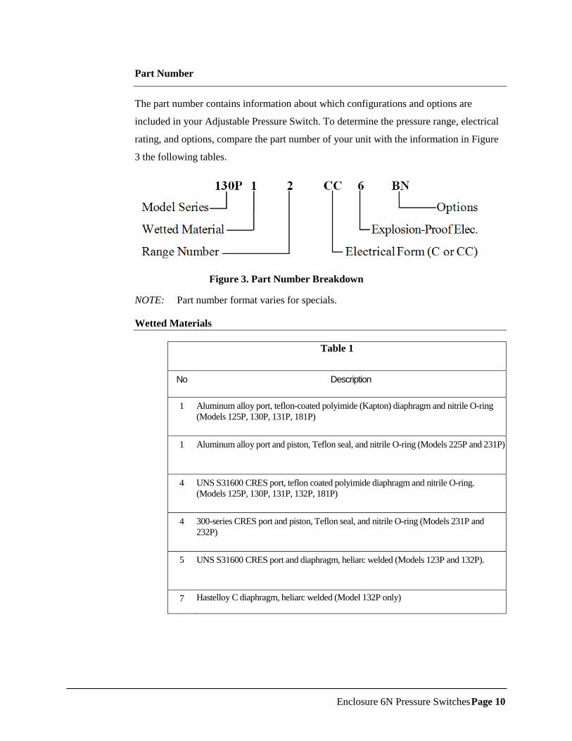
Part Number
The part number contains information about which configurations and options are
included in your Adjustable Pressure Switch. To determine the pressure range, electrical
rating, and options, compare the part number of your unit with the information in Figure
3 the following tables.
Figure 3. Part Number Breakdown
NOTE: Part number format varies for specials.
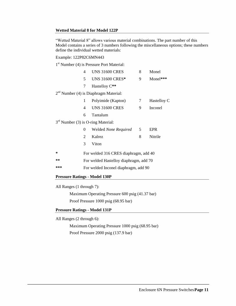
Wetted Materials
Table 1
No Description
1 Aluminum alloy port, teflon-coated polyimide (Kapton) diaphragm and nitrile O-ring
(Models 125P, 130P, 131P, 181P)
1 Aluminum alloy port and piston, Teflon seal, and nitrile O-ring (Models 225P and 231P)
4 UNS S31600 CRES port, teflon coated polyimide diaphragm and nitrile O-ring.
(Models 125P, 130P, 131P, 132P, 181P)
4 300-series CRES port and piston, Teflon seal, and nitrile O-ring (Models 231P and
232P)
5 UNS S31600 CRES port and diaphragm, heliarc welded (Models 123P and 132P).
7 Hastelloy C diaphragm, heliarc welded (Model 132P only)
Enclosure 6N Pressure Switches Page 11
Wetted Material 8 for Model 122P
“Wetted Material 8” allows various material combinations. The part number of this
Model contains a series of 3 numbers following the miscellaneous options; these numbers
define the individual wetted materials:
Example: 122P82C6MN443
1st Number (4) is Pressure Port Material:
4 UNS 31600 CRES 8 Monel
5 UNS 31600 CRES* 9 Monel***
7 Hastelloy C**
2nd
Number (4) is Diaphragm Material:
1 Polyimide (Kapton) 7 Hastelloy C
4 UNS 31600 CRES 9 Inconel
6 Tantalum
3rd
Number (3) is O-ring Material:
0 Welded None Required 5 EPR
2 Kalrez 8 Nitrile
3 Viton
* For welded 316 CRES diaphragm, add 40
** For welded Hastelloy diaphragm, add 70
*** For welded Inconel diaphragm, add 90
Pressure Ratings - Model 130P
All Ranges (1 through 7):
Maximum Operating Pressure 600 psig (41.37 bar)
Proof Pressure 1000 psig (68.95 bar)
Pressure Ratings - Model 131P
All Ranges (2 through 6):
Maximum Operating Pressure 1000 psig (68.95 bar)
Proof Pressure 2000 psig (137.9 bar)
Enclosure 6N Pressure Switches Page 12
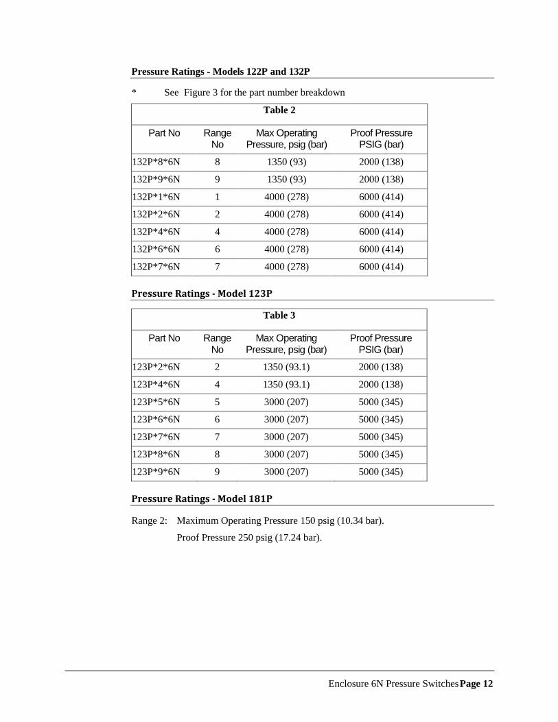
Pressure Ratings - Models 122P and 132P
* See Figure 3 for the part number breakdown
Table 2
Part No Range No
Max Operating Pressure, psig (bar)
Proof Pressure PSIG (bar)
132P*8*6N 8 1350 (93) 2000 (138)
132P*9*6N 9 1350 (93) 2000 (138)
132P*1*6N 1 4000 (278) 6000 (414)
132P*2*6N 2 4000 (278) 6000 (414)
132P*4*6N 4 4000 (278) 6000 (414)
132P*6*6N 6 4000 (278) 6000 (414)
132P*7*6N 7 4000 (278) 6000 (414)
Pressure Ratings - Model 123P
Table 3
Part No Range No
Max Operating Pressure, psig (bar)
Proof Pressure PSIG (bar)
123P*2*6N 2 1350 (93.1) 2000 (138)
123P*4*6N 4 1350 (93.1) 2000 (138)
123P*5*6N 5 3000 (207) 5000 (345)
123P*6*6N 6 3000 (207) 5000 (345)
123P*7*6N 7 3000 (207) 5000 (345)
123P*8*6N 8 3000 (207) 5000 (345)
123P*9*6N 9 3000 (207) 5000 (345)
Pressure Ratings - Model 181P
Range 2: Maximum Operating Pressure 150 psig (10.34 bar).
Proof Pressure 250 psig (17.24 bar).
Enclosure 6N Pressure Switches Page 13
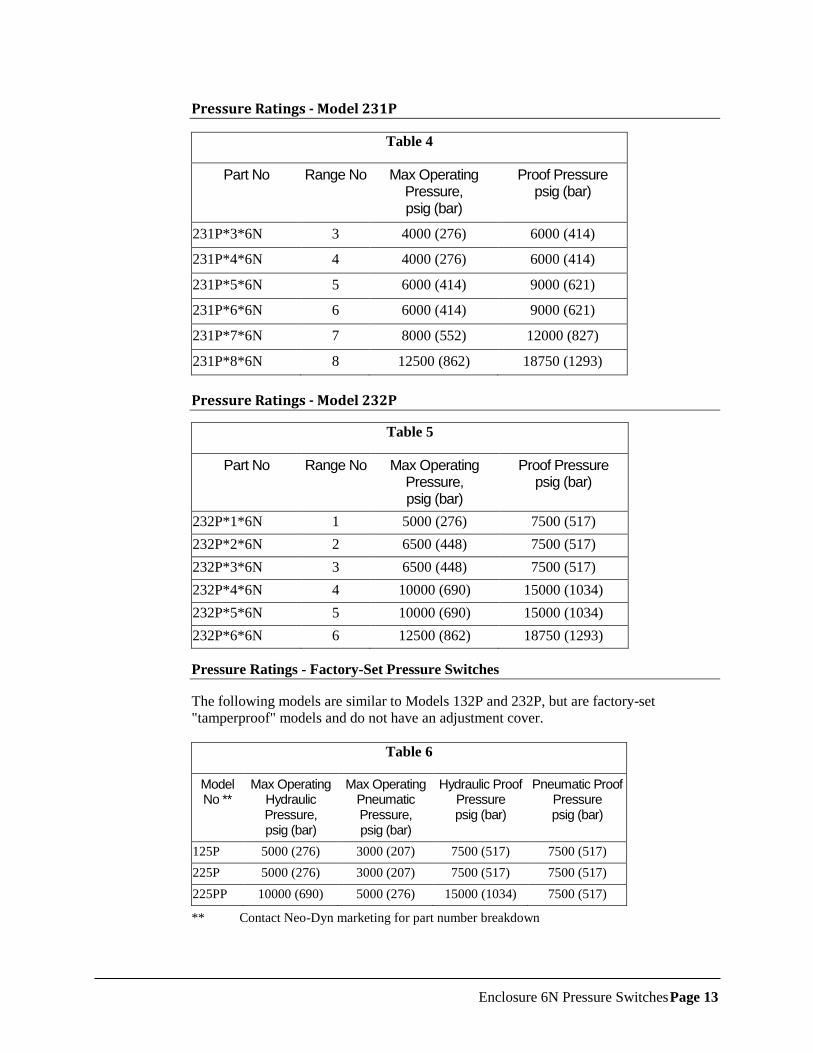
Pressure Ratings - Model 231P
Table 4
Part No Range No Max Operating Pressure, psig (bar)
Proof Pressure psig (bar)
231P*3*6N 3 4000 (276) 6000 (414)
231P*4*6N 4 4000 (276) 6000 (414)
231P*5*6N 5 6000 (414) 9000 (621)
231P*6*6N 6 6000 (414) 9000 (621)
231P*7*6N 7 8000 (552) 12000 (827)
231P*8*6N 8 12500 (862) 18750 (1293)
Pressure Ratings - Model 232P
Table 5
Part No Range No Max Operating Pressure, psig (bar)
Proof Pressure psig (bar)
232P*1*6N 1 5000 (276) 7500 (517)
232P*2*6N 2 6500 (448) 7500 (517)
232P*3*6N 3 6500 (448) 7500 (517)
232P*4*6N 4 10000 (690) 15000 (1034)
232P*5*6N 5 10000 (690) 15000 (1034)
232P*6*6N 6 12500 (862) 18750 (1293)
Pressure Ratings - Factory-Set Pressure Switches
The following models are similar to Models 132P and 232P, but are factory-set
"tamperproof" models and do not have an adjustment cover.
Table 6
Model No **
Max Operating Hydraulic Pressure, psig (bar)
Max Operating Pneumatic Pressure, psig (bar)
Hydraulic Proof Pressure psig (bar)
Pneumatic Proof Pressure psig (bar)
125P 5000 (276) 3000 (207) 7500 (517) 7500 (517)
225P 5000 (276) 3000 (207) 7500 (517) 7500 (517)
225PP 10000 (690) 5000 (276) 15000 (1034) 7500 (517)
** Contact Neo-Dyn marketing for part number breakdown
Enclosure 6N Pressure Switches Page 14
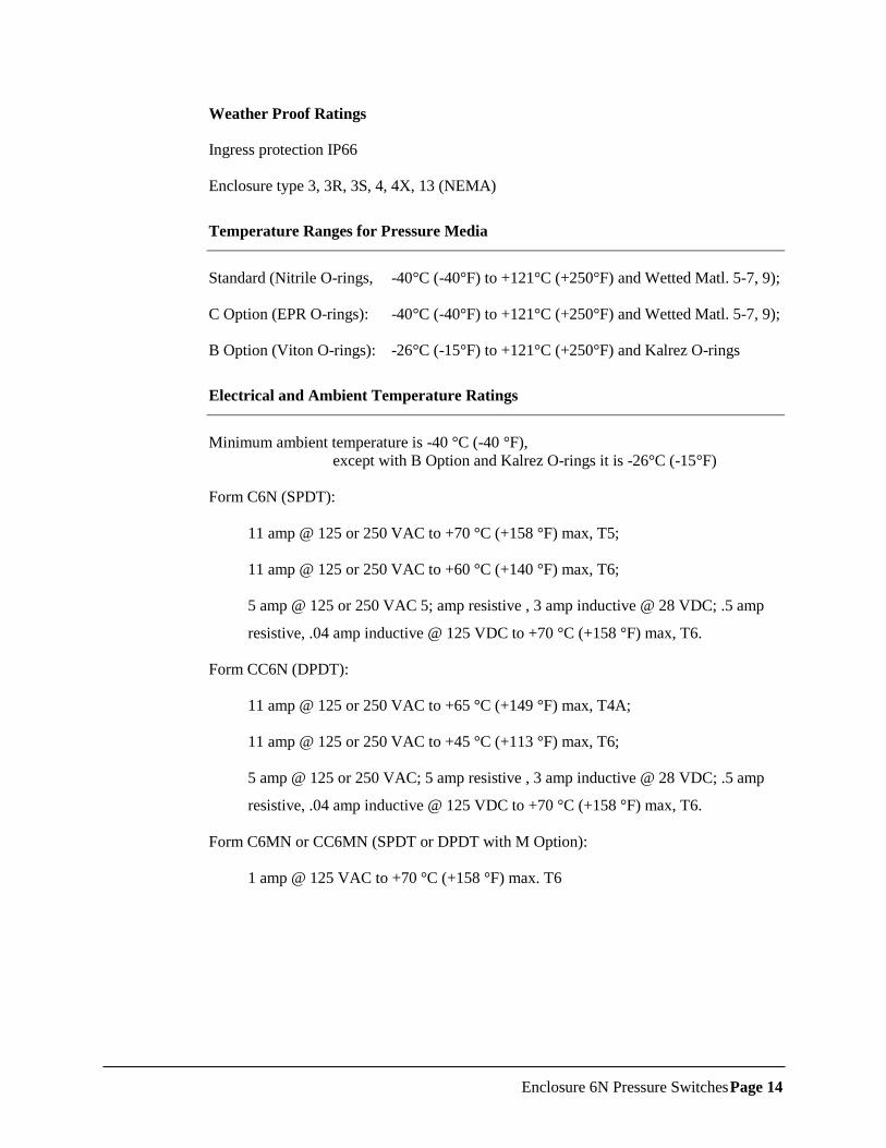
Weather Proof Ratings
Ingress protection IP66
Enclosure type 3, 3R, 3S, 4, 4X, 13 (NEMA)
Temperature Ranges for Pressure Media
Standard (Nitrile O-rings, -40°C (-40°F) to +121°C (+250°F) and Wetted Matl. 5-7, 9);
C Option (EPR O-rings): -40°C (-40°F) to +121°C (+250°F) and Wetted Matl. 5-7, 9);
B Option (Viton O-rings): -26°C (-15°F) to +121°C (+250°F) and Kalrez O-rings
Electrical and Ambient Temperature Ratings
Minimum ambient temperature is -40 °C (-40 °F),
except with B Option and Kalrez O-rings it is -26°C (-15°F)
Form C6N (SPDT):
11 amp @ 125 or 250 VAC to +70 °C (+158 °F) max, T5;
11 amp @ 125 or 250 VAC to +60 °C (+140 °F) max, T6;
5 amp @ 125 or 250 VAC 5; amp resistive , 3 amp inductive @ 28 VDC; .5 amp
resistive, .04 amp inductive @ 125 VDC to +70 °C (+158 °F) max, T6.
Form CC6N (DPDT):
11 amp @ 125 or 250 VAC to +65 °C (+149 °F) max, T4A;
11 amp @ 125 or 250 VAC to +45 °C (+113 °F) max, T6;
5 amp @ 125 or 250 VAC; 5 amp resistive , 3 amp inductive @ 28 VDC; .5 amp
resistive, .04 amp inductive @ 125 VDC to +70 °C (+158 °F) max, T6.
Form C6MN or CC6MN (SPDT or DPDT with M Option):
1 amp @ 125 VAC to +70 °C (+158 °F) max. T6
Enclosure 6N Pressure Switches Page 15
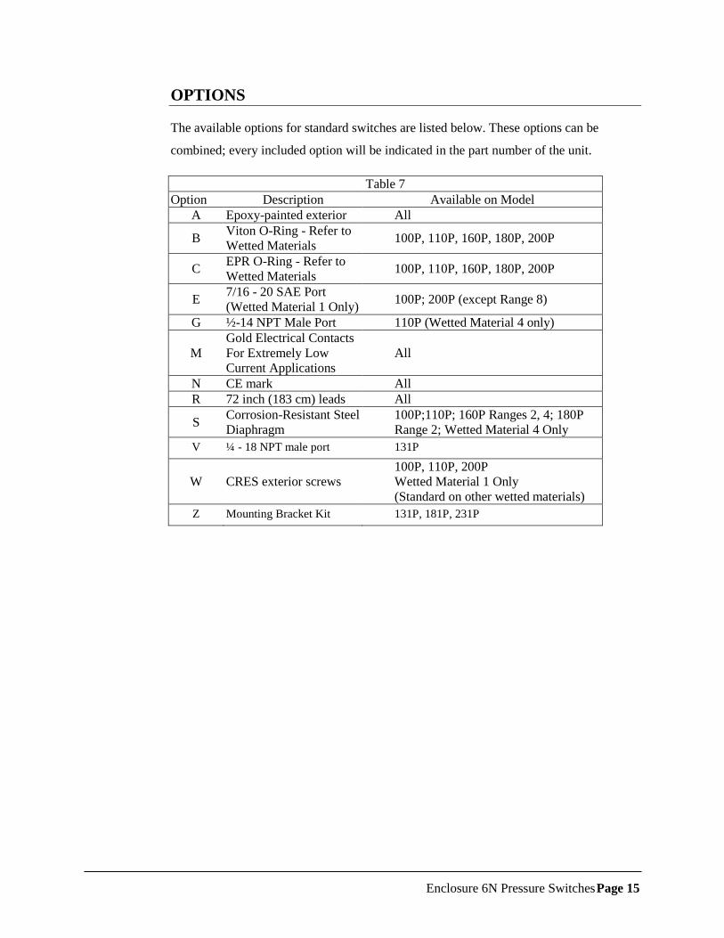
OPTIONS
The available options for standard switches are listed below. These options can be
combined; every included option will be indicated in the part number of the unit.
Table 7
Option Description Available on Model
A Epoxy-painted exterior All
B Viton O-Ring - Refer to
Wetted Materials 100P, 110P, 160P, 180P, 200P
C EPR O-Ring - Refer to
Wetted Materials 100P, 110P, 160P, 180P, 200P
E 7/16 - 20 SAE Port
(Wetted Material 1 Only) 100P; 200P (except Range 8)
G ½-14 NPT Male Port 110P (Wetted Material 4 only)
M
Gold Electrical Contacts
For Extremely Low
Current Applications
All
N CE mark All
R 72 inch (183 cm) leads All
S Corrosion-Resistant Steel
Diaphragm
100P;110P; 160P Ranges 2, 4; 180P
Range 2; Wetted Material 4 Only
V ¼ - 18 NPT male port 131P
W CRES exterior screws
100P, 110P, 200P
Wetted Material 1 Only
(Standard on other wetted materials)
Z Mounting Bracket Kit 131P, 181P, 231P
Enclosure 6N Pressure Switches Page 16
WARRANTY INFORMATION
A. Warranty:
ITT Industries (ITT) warrants that at the time of shipment, the products manufactured by
ITT Neo-Dyn® and sold hereunder, will be free from defects in material and
workmanship and will conform to the specifications furnished or approved by ITT.
B. Warranty Adjustment:
If any defect within this warranty appears, the Buyer shall notify ITT immediately.
ITT agrees to repair or furnish a replacement for, but not install, any product which,
within one (1) year from the date of shipment by ITT shall, upon test and examination by
ITT, prove defective within the above warranty.
No product will be accepted for return or replacement without the written authorization
of ITT. Upon such authorization, and in accordance with instructions by ITT, the product
will be returned with shipping charges prepaid by the Buyer. Replacements made under
this warranty will be shipped prepaid.
C. Exclusion from Warranty:
THE FOREGOING WARRANTY IS IN LIEU OF AND EXCLUDES ALL OTHER
EXPRESSED OR IMPLIED WARRANTIES OF MERCHANTABILITY, OR FITNESS, OR
OTHERWISE.
Components manufactured by any supplier other than ITT shall bear only the warranty
made by the manufacturer of that product, and ITT assumes no responsibility for the
performance or reliability of the unit as a whole.
In no event shall ITT be liable for indirect, incidental or consequential damages nor shall
the liability of ITT arising in connection with any products sold hereunder (whether such
liability arises from a claim based on contract, warranty, tort or otherwise) exceed the
actual amount paid by Buyer to ITT for the products delivered hereunder.
The warranty does not extend to any product manufactured by ITT, which has been
subject to misuse, neglect, accident, improper installation, or to use in violation of
instructions furnished by ITT.
The warranty does not extend to or apply to any unit, which has been repaired or altered
at any place other than at ITT’s factory or service locations, by persons not expressly
approved by ITT.