Embed Size (px)
Citation preview

1
INSTALLATION AND OWNER’S MANUAL I MAN 994310, rev C
December 2005
12000LR - 12000 Pound Capacity
12000LRD - 12000 Pound Capacity x 2

2
TABLE OF CONTENTS Important Information…………………………………………………………..2 Section 1 Owner’s Manual Safety Instructions........................................................................................ 3 Operating Instructions……………………………………………………………4 Monthly Maintenance…………………………………………………………….4 Troubleshooting…………………………………………………………………..5 Section 2 Installation Instructions Tools Required for Installation…………….……………………………………7 Procedure…………………………………………………………………...........7 Section 3 Parts Breakdown Parts List…………………………………………………………………………25
Important Information: 1. Read this manual thoroughly before installing, operating, or maintaining this lift.
2. This lift is designed for indoor use only, and should not be installed in a pit or de-pression.
3. The floor on which the lift is to be installed must be 4” inch minimum thickness con-crete, with a minimum compressive strength of 3000 psi, and reinforced with steel bar.
4. The lifts require 208-230V, 60 hz, single phase, 20 amp AC electrical service.
5. The lift has a minimum ceiling height requirement as described in the Installation In-structions section of the manual.
6. This multi-lift system has specific requirements for bay door spacing. See pages 9-12 for the specifications of your lift.
7. This lift is designed to be leveled to accommodate sloping floors.
8. Failure by the owner to provide the recommended shelter, mounting surface, electrical supply, and ceiling height could result in unsatisfactory lift per-formance, property damage, or personal injury.

3
SECTION 1. OWNER’S MANUAL
SAFETY INSTRUCTIONS
1. Do not raise a vehicle on the lift until the installation is completed as de-scribed in this manual.
2. Anyone who will be in the vicinity of the lift when it is in use should read and re-fer to the following publications supplied with this lift:
• “INSTALLATION AND OWNERS MANUAL”, I MAN 994333 • “LIFTING IT RIGHT”, ALI SM93-1. • “AUTOMOTIVE LIFT SAFETY TIPS”, ALI-ST90. • “SAFETY REQUIREMENTS FOR OPERATION, INSPECTION, AND
MAINTENANCE”, ANSI/ALI ALOIM-1994.
3. Technicians should be trained to use and care for the lift by familiarizing them-selves with the publications listed above. The lift should never be operated by an untrained person.
4. Do not overload the lift. The capacity of the lift is shown on cover of this docu-ment.
5. Keep everyone clear of the lift when the lift is moving, the locking mechanism is disengaged, or the vehicle is in danger of falling.
6. Unauthorized personnel should never be in the shop area when the lift is in use.
7. Inspect the lift daily. The lift should never be operated if it has damaged compo-nents, or is malfunctioning. Only qualified technicians should service the lift. Re-place damaged components with manufacturer’s parts, or equivalent.
8. Keep the area around the lift clear of obstacles.
9. Never override the self-returning lift controls.
10. To reduce the risk of personal injury, keep hair, loose clothing, fingers, and all body parts away from moving parts.
11. To reduce the risk of electric shock, do not use the lift when wet, do not expose the lift to rain.
12. To reduce the risk of fire, do not operate equipment in the vicinity of open con-tainers of flammable liquids (gasoline).
13. Use the lift only as described in this manual, use only manufacturer’s recom-mended attachments.
14. Unusual vehicles, such as limousines, RV’s, and long wheelbase vehicles, may not be suitable for lifting on this equipment. If necessary, consult with the manufacturer or the manufacturer’s representative.
15. The troubleshooting and maintenance procedures described in this manual can be done by the lift’s owner/employer. Any other procedure should be performed by

4
trained lift service personnel only. These restricted procedures include, but are not limited to, the following: cylinder replacement, safety latch replacement, and leg re-placement.
OPERATING INSTRUCTIONS RAISING VEHICLES
1. Drive vehicle onto lift. Set Parking Brake. 2. Push button on power unit to raise lift to desired height. 3. Use the lever on the power unit to lower the lift onto the safety latch. 4. Before walking under the lift, verify that the safety latch pivot pin is positioned in
the latch rack under the toprail tube. LOWERING VEHICLES
1. Raise the lift off of the safety latch using the push button switch on the power unit.
2. Release the safety latch by holding down on the latch until the cam sets to hold it down.
3. Lower the lift using the valve lever on the power unit.
MONTHLY MAINTAINANCE 1. With lift lowered check the hydraulic fluid level. If necessary add oil as described in
the Installation Instruction section of this manual 2. Check the safety latch mechanism: correct alignment of legs and crossrails, and
correct linkage problems as required. 3. Check tightness of all bolts. 4. Check anchor bolt tightness. If the anchor bolts are loose, they should be re-
torqued to 90ft/lbs.
• Check the nuts for tightness every week for the first month, and every month afterwards.
5. Lubricate the lifting and crossrail chains with a quality chain lubricant. 6. Replace worn or broken parts only with lift manufacturer’s parts, or their equivalent.
TROUBLE SHOOTING INSTRUCTIONS 1. Lift will not raise or raises part way.
• Not enough oil in the reservoir. • The electrical hook up is not 220V or the voltage is not adequate for the pump
motor. Check for a minimum of 208V at the power unit while the motor is running under load.
• Foreign matter in valving. Hold the lowering control in and run the motor with the push button switch for 60 seconds to flush the system. Repeat several times.
2. Lift will not pick up a heavy vehicle.

5
• The lift is overloaded. The lift is rated to pick up 12,000 lb. The relief valve will not allow overloading.
• The voltage at the power unit is not adequate. Check for a minimum of 208 V at the power unit while the motor is running under load.
• The piston seal of the cylinder is damaged. Raise the lift to full height. Dis-connect the return line at the power unit and place the hose end in a bucket. Run the power unit at the full relief valve bypass setting. A flow of oil from the hose indicates a bad piston seal.
3. Lift drifts down when the push button is released.
• Foreign matter in valving. Hold the lowering control in and run the motor with the push button switch for 60 seconds to flush the system. Repeat several times.
4. Toprail safety latch does not work smoothly.
• Latch ear drags on one side of the top rail tube. Adjust the cylinder position by bending the cylinder locating ears on top of the tube near the rod end of the cylinder. If this does not solve the problem, loosen the attachment nuts on the latch pivot pin. If this stops the problem, space out the latch ears us-ing ¾ flat washers. The figure on the following page shows latch assembly.
• Latch will not stay up for reset and lowering. Check the cam for free opera-tion. If the latch drops during lowering, see step just above.

6
5. Oil leaks.
• Power Unit. If the power unit leaks hydraulic oil around the tank mounting flange,
check the oil level in the tank by removing the bleed screw just below the top of the tank.
• Cylinder.
Some seepage from the rod end of the cylinder is normal. Oil in minute quantities adheres to the rod when the lift is lowered. The oil is removed by the rod wiper when the lift is raised. This oil will drip down and collect on the top rail. To check for a leak condition, raise the lift until the cylinder bottoms out. Hold the power unit run button for one minute. The system pressure at this time will be the maximum and the cylinder will leak if the seals are bad.

7
SECTION 2. INSTALLATION INSTRUCTIONS TOOLS FOR INSTALLATION
• Concrete hammer drill with ½” and ¾” diameter bit • Open end wrenches: ½, 9/16, 11/16, ¾ • Hex head allen wrenches: 3/16 • Ratchet Drive with sockets: 3/8, ½ deep socket • 12” crescent wrench • Hammer • Needle nose pliers • Level, 3’ minimum • Pull wire • Chalk line • Small punch
PROCEDURE 1. Read the Notices on the first page.
• Determine the location for the lift(s) installation. Figures 1 and 2 give the overall dimensions of the lift(s) installation, including the drive on ramps. The area must be level and there must be free access to load and unload the ve-hicles.
• There must be enough overhead clearance to raise vehicles 6 feet above the floor. 13 feet is the recommended ceiling height.
2. If you are installing a Double Lube lift, refer again to Figure 1 to understand the posi-
tioning of the components of the lift. The centerlines of the two sets of runways are on a 12’ spacing. They should correspond approximately with the centerlines of the two bays.
3. Refer to Figure 2 to begin the process of positioning the lifts in the bays. If you are installing a Double Lube Lift, locate and mark with a chalk line the centerline be-tween the two bays. Mark two lines parallel to this centerline, lines A-B, 9-3/4” either side of the centerline. If you are installing a Single Lube Lift, you’ll only be con-cerned with one set of chalk lines centered within the bay.
4. Use the 11’, 3-1/2” width dimension to draw the arcs A-D and B-C. Draw chalk lines D-C tangent to their respective arcs.
5. Refer again to Figures 1 and 2 to determine where to locate the ends of the leg foot rectangle with respect to walls and other obstacles. Mark on lines A-B points 1 and 2 to establish the ends of the leg foot rectangle. From points 1 and 2 measure di-agonally 20’, 6-1/2” to the opposite parallel line to determine points 3 and 4. Draw a chalk line between points 1 and 4 and points 2 and 3. The four lines locate the four corners of the leg foot rectangle.

8
Figure 1

9
Figure 2

10
LEFT HAND LIFT INSTALLATION 6. If you are installing a Single Lube Lift, skip this section and move on to step 34;
RIGHT HAND / SINGLE LIFT SUPERSTRUCTURE INSTALLATION. 7. Refer to Figure 1. If there is good access to both sides of the installation, the best
procedure is to place the tracks on blocks on the floor in their final positions and then stand up the mainside leg/top rail assemblies from each side. If one side of the in-stallation is blocked, the mainside leg/top rail assembly for that side should be posi-tioned first, the tracks positioned on blocks second, and then the second top rail erected. This manual will proceed under the assumption that there is good access to both sides of the installation.
8. Unpack and disassemble the lifts. Save all the packing hardware. Position both sets of mainside and offside tracks on blocks in their respective bays.
9. Locate the toprail with additional mounting tab located at the end of the toprail. Position this toprail and mainside legs for the left hand lift as shown in Figure 3. The cylinder is positioned with its ear end at the front of the lift. The toprail should be resting on blocks to assist in positioning the parts. The Power Unit leg has a formed bracket on one side for mounting the power unit. This leg should be located on the rear of the lift. Bolt the toprail to the mainside legs using the ½ x 1-3/4 bolts, wash-ers, and nuts provided. See Figure 3.
10. Lift the assembled toprail and legs to the upright position. Place the leg feet into their corners of the chalk line rectangle. Check the centering of the bolting slots of the toprail and mainside leg tops. Correct as necessary and tighten the nuts.
Figure 3
11
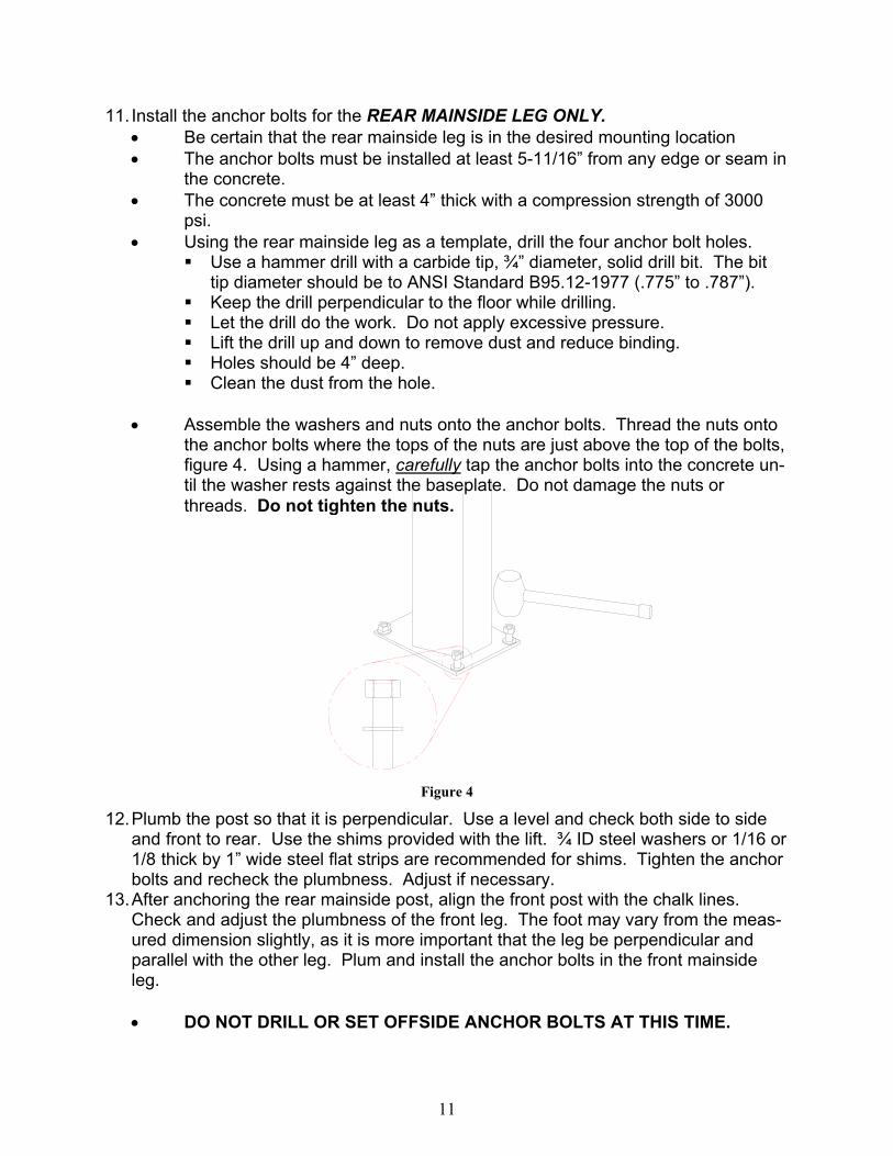
11. Install the anchor bolts for the REAR MAINSIDE LEG ONLY. • Be certain that the rear mainside leg is in the desired mounting location • The anchor bolts must be installed at least 5-11/16” from any edge or seam in
the concrete. • The concrete must be at least 4” thick with a compression strength of 3000
psi. • Using the rear mainside leg as a template, drill the four anchor bolt holes.
Use a hammer drill with a carbide tip, ¾” diameter, solid drill bit. The bit tip diameter should be to ANSI Standard B95.12-1977 (.775” to .787”).
Keep the drill perpendicular to the floor while drilling. Let the drill do the work. Do not apply excessive pressure. Lift the drill up and down to remove dust and reduce binding. Holes should be 4” deep. Clean the dust from the hole.
• Assemble the washers and nuts onto the anchor bolts. Thread the nuts onto
the anchor bolts where the tops of the nuts are just above the top of the bolts, figure 4. Using a hammer, carefully tap the anchor bolts into the concrete un-til the washer rests against the baseplate. Do not damage the nuts or threads. Do not tighten the nuts.
Figure 4
12. Plumb the post so that it is perpendicular. Use a level and check both side to side and front to rear. Use the shims provided with the lift. ¾ ID steel washers or 1/16 or 1/8 thick by 1” wide steel flat strips are recommended for shims. Tighten the anchor bolts and recheck the plumbness. Adjust if necessary.
13. After anchoring the rear mainside post, align the front post with the chalk lines. Check and adjust the plumbness of the front leg. The foot may vary from the meas-ured dimension slightly, as it is more important that the leg be perpendicular and parallel with the other leg. Plum and install the anchor bolts in the front mainside leg.
• DO NOT DRILL OR SET OFFSIDE ANCHOR BOLTS AT THIS TIME.
12
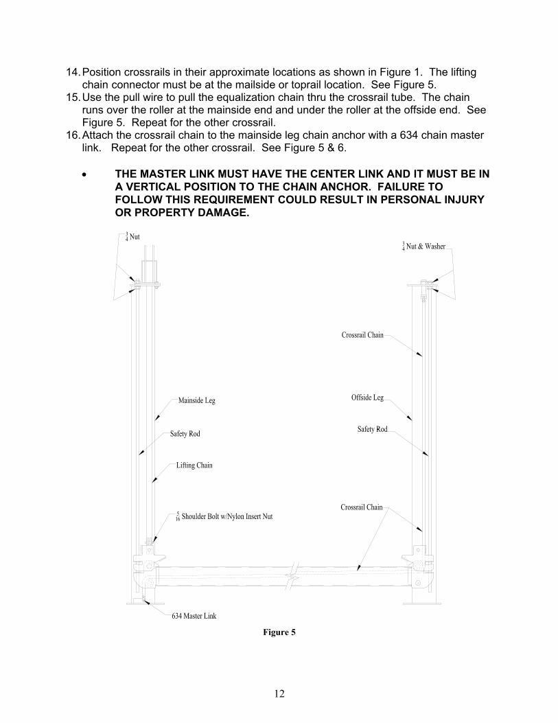
14. Position crossrails in their approximate locations as shown in Figure 1. The lifting chain connector must be at the mailside or toprail location. See Figure 5.
15. Use the pull wire to pull the equalization chain thru the crossrail tube. The chain runs over the roller at the mainside end and under the roller at the offside end. See Figure 5. Repeat for the other crossrail.
16. Attach the crossrail chain to the mainside leg chain anchor with a 634 chain master link. Repeat for the other crossrail. See Figure 5 & 6.
• THE MASTER LINK MUST HAVE THE CENTER LINK AND IT MUST BE IN
A VERTICAL POSITION TO THE CHAIN ANCHOR. FAILURE TO FOLLOW THIS REQUIREMENT COULD RESULT IN PERSONAL INJURY OR PROPERTY DAMAGE.
Figure 5

13
17. Position a 2 x 4 block under the safety latch on the mainside end of the crossrail as shown in Figure 6. Install a ¾ nut onto the safety rod and turn it down to the end of the threads on the rod. Remove the nail from the top end of the packing pin in the crossrail. Push the pin down and out using the safety rod, leaving the safety rod in the latch mechanism. While pulling up on the safety latch and while a helper pulls on the other end of the crossrail chain, insert the top of the safety rod into the rear hole at the top of the mainside leg and slide the crossrail end into the mainside leg. Secure the top of the safety rod with a ¾ nut. The top nut should be flush with the end of the safety rod and the bottom nut should be tightened against the leg top. Remove the wooden block. Repeat this procedure for the other three corners.
Figure 6
18. Install the bolt end of the crossrail chain in to the hole at the top of the offside leg.
Attach the 1” washer and nylon insert nut to the bolt. Hold the chain with a crescent wrench while tightening the nut to remove most of the slack from the chain. Repeat for the other crossrail.

14
19. Secure four 5/16 x 1-1/4 NC bolts onto the power unit mount bracket with 5/16 hex nuts. See Figure 7.
Figure 7
20. Mount the power unit onto the four bolts with 5/16 nylon insert nuts. See Figure 8.
Figure 8

15
21. It is advisable to use compressed air to extend the cylinder ram. Remove the port
caps from the cylinder carefully and gradually apply compressed air to the cylinder port near the rear or pin end of the cylinder. Do not allow the cylinder ram to shoot out of the cylinder. It is necessary to pull down on the lifting chains as the ram ex-tends. • If compressed air is not available, the cylinder ram can be pulled out manu-
ally. 22. On the Power Unit, the port immediately to the right of the lowering handle is the
high pressure port. Install the O-Ring to 3/8 male JIC elbow. 23. Install the 3/8 male pipe to 3/8 JIC 90 fitting into the front or rod end cylinder ports.
Use teflon pipe tape on the pipe threads of the fittings. 24. Connect the high pressure hose to the above mentioned fittings. 25. Install the 3/8NPT to 1/4NPT adapter and 1/4NPT to ¼ Tube 90 degree elbow to the
rear or pin end port of the cylinder. 26. Connect the plastic tube to the above mentioned fittings, trimming the length to fit. 27. Remove the screw in the tank just below the tank mounting flange. Using a funnel in
the breather fitting on the power unit, fill the reservoir until oil appears at the screw hole. Use approximately 11 quarts of petroleum based (mineral) oil, non foaming, non detergent, such as Mobil DTE 25 or Texaco HD 46. Install the breather cap and replace the screw.
• Do not overfill the oil tank. The oil level should be no higher than two
inches below the mounting flange of the tank.
28. Make the 220 Volt Single Phase electrical hookup to the power unit. See Figure 9.
Figure 9

16
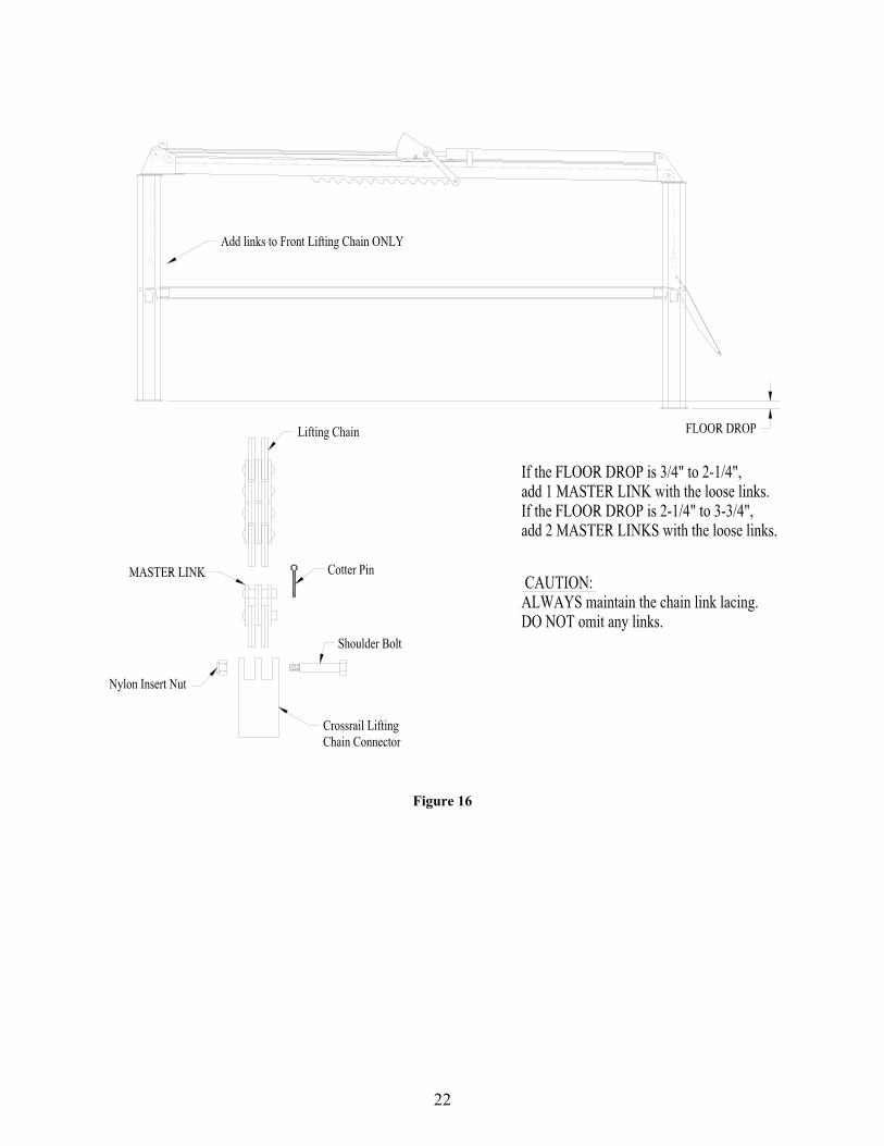
29. Attach the lifting chains to each crossrail chain connector using the Grade 8 shoul-der bolt 5/16 x 1-1/2 long and ¼ nut. The floor may slope significantly from the front of the lift to the rear. If the slope is known, apply the necessary corrective measure as indicated in Figure 13. • Failure to use the correct bolt may result in personal injury or property
damage.
30. Using the power unit, raise the crossrails enough to pick up the tracks. Level the
cross rails by adjusting the crossrail chain tension at the anchor bolt nut at the top of the offside legs. Use a level to check the crossrails.
31. Lower the tracks to the ground. Position the two tracks according to the dimensions shown in Figure 12, Track Positioning. Make sure that the tracks, crossrails, and

17
legs are square with each other and positioned evenly. Install the U-bolts at the front and rear of each track to the outside of the tracks.
32. Raise the tracks 6” above the ground. Adjust and plum the offside legs so that the crossrail chains in the offside legs hang straight as indicated by a level, the lifting chains in the mainside legs hang straight, the crossrails hang in the center of the leg opening, the legs are plumb, and the tracks are positioned correctly.
33. Raise the lift to the top of its travel. Check the positioning of the crossrails in the legs as the lift is raised. The single point safety release will move across the rack at the bottom of the toprail. At the top of the lift’s travel, pull down the safety release until the cam locks it down. Lower the lift. Check the operation and positioning of the lift as it is being lowered. Correct any problems by adjusting the position and plumbness of the offside legs. If the toprail safety latch mechanism does not work correctly, refer to the Troubleshooting section of this manual.
34. When the lift is operating correctly, drill and install the anchor bolts for the offside legs. • The offside legs may vary slightly from the chalk line layout positions.
It is more important that the legs be square and plumb to the floor and that the lift move up and down freely.
RIGHT HAND/SINGLE LIFT INSTALLATION 35. Locate the toprail without the additional mounting tabs. Position this toprail and
mainside legs for the right hand lift as shown in Figure 3. The cylinder is positioned with its ear end at the rear of the lift. The toprail should be resting on blocks to as-sist in positioning the parts. The Power Unit leg has a formed bracket on one side for mounting the power unit. This leg should be located on the rear of the lift. Bolt the top rail to the mainside legs using the ½ x 1-3/4 bolts, washers, and nuts pro-vided.
36. Proceed with the installation as described above for the left hand installation. When the time comes to position the front left (offside) leg, refer to Figure 1 and Figure 11, Vacuum Platform Mounting. Install the Offside Vacuum Platform under the nuts for the safety rod and the cross chain anchor.
WALKWAY, HANDRAILS, AND OIL PAN INSTALLATION 37. Position the center walkways on both lifts. Raise the lifts to a convenient working
height. 38. Complete the installation of the center walkway by securing it to the tracks with ½ x
1 hex head bolts and washers. 39. Attach the balcony to the left hand lift using 4 each ½ x 1-3/4 bolts, washers and
nuts. 40. Figure 15. Attach the balcony handrails using the 3/8 x 2 bolts. 41. Place blocks that are at least 6” high under the rear of each track. Lower the tracks
onto the blocks and continue to lower the lift until the mainside end of the rear cross rail drops below the inside flange of the mainside track.
42. KEEPING FEET AWAY FROM UNDER THE CROSSRAIL, support the offside end of the crossrail with one hand and carefully pull up on the offside slack chain latch

18
with the other end to lower that end of the crossrail. Slide the oil tank into the track with the drain valve to the rear of the tracks. Raise the lift with the power unit until the rear cross rail is up to the track end plates.
2. It may be necessary to install or adjust the oil pan brake.
• Insert the pins thru the holes and springs and thread into the brake flat.
Figure 10
• Insert the brake handle through the holes in the pins.
Figure 11
• Assemble the nuts and cam onto the end of the handle.
Figure 12

19
43. Orient the threaded cam to the same position as the welded cam and lock into place with the nuts.
Figure 13
44. Check the location of the tracks to obtain the dimensions shown in Figure 15. Se-cure the front and rear of each track with 2 U-bolts and hardware.
• The U-bolts should be ground off at the top of the nut to protect tires. 45. Remove the blocks and raise both lifts to about 2’. Refer to Figure 17 & 18 for railing
assemblies. For each lift, position the mainside front post, the front handrail, and the front rail angle as shown. Secure with ½ x 1-3/4 hex head bolts, nuts, and washers. Attach the front rail to the rail angle with 3/8 x 2 hex head bolts.
46. Attach the offside and mainside handrails to the tracks using the 3/8 x 2 hex head bolts. The two rails on the long track are bolted to each other using 3/8 x 3 hex head bolts Attach the offside and mainside corner rails with 3/8 x 2 hex head bolts.
47. Install the front gates by dropping them onto the hinges on the front posts. Attach the spring to each gate using the tab on the gate front and the tab on the post. In-stall the gate latch onto the mainside rail with two 5/16” x 1 bolts and hardware.
48. At the rear of the tracks, install the mainside rear post using ½ x 1-3/4 hex head bolts with nuts and washers, and the mainside corner rails with 3/8 x 2 hex head bolts with hardware.
49. Install the drive on ramps at the rear of the tracks using the ¾ diameter ramp pins and secure with cotters pins.
20
50. Install the wheels on the ladders using the ½” diameter x 21-1/2 rod and the ½” ny-lon insert nuts.
51. Install the ladders using the ½” x 18-1/2” rod and nuts. 52. Install the safety chains on the rings on the balcony rails and the left side handrails
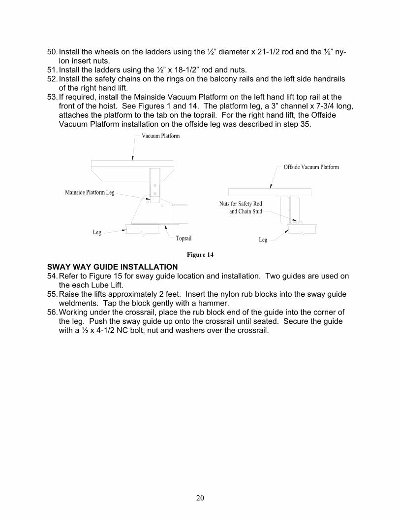
of the right hand lift. 53. If required, install the Mainside Vacuum Platform on the left hand lift top rail at the
front of the hoist. See Figures 1 and 14. The platform leg, a 3” channel x 7-3/4 long, attaches the platform to the tab on the toprail. For the right hand lift, the Offside Vacuum Platform installation on the offside leg was described in step 35.
Figure 14
SWAY WAY GUIDE INSTALLATION 54. Refer to Figure 15 for sway guide location and installation. Two guides are used on
the each Lube Lift. 55. Raise the lifts approximately 2 feet. Insert the nylon rub blocks into the sway guide
weldments. Tap the block gently with a hammer. 56. Working under the crossrail, place the rub block end of the guide into the corner of
the leg. Push the sway guide up onto the crossrail until seated. Secure the guide with a ½ x 4-1/2 NC bolt, nut and washers over the crossrail.

21
Figure 15
22
Figure 16

23
Figure 17

24
Figure 18

25
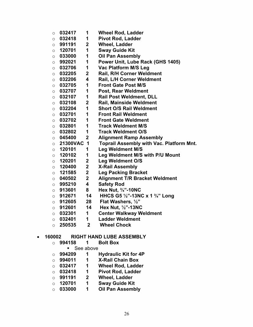
DOUBLE LUBE LIFT, MODEL 160000 • 160001 1 LEFT HAND LUBE ASSEMBLY
o 994158 1 Bolt Box 994310 1 Installation Manual, Lube Lifts 911403 2 Nyloc Hex Nut, ¼”-20NC 911703 14 Nyloc Hex Nut, 5/16”-18NC 911705 20 Flat Washer, 5/16” 911741 10 HHCS G5 5/16”-18NC x 1” Lg 911751 3 HHCS G5 5/16”-18NC x 1 ¼” Lg 911701 4 Hex Nut, 5/16”-18NC 911841 2 SHSB 5/16” x 1 ½” 912003 65 Nyloc Hex Nut, 3/8”-16NC 912005 130 Flat Washer, 3/8” 912081 61 HHCS G5 3/8”-16NC x 2” Lg 912121 1 HHCS G5 3/8”-16NC x 3” Lg 912603 30 Nyloc Hex Nut, ½”-13NC 912605 44 Flat Washer, ½” 912606 4 SAE Washer, ½” 912641 4 HHCS G5 ½”-13NC x 1” Lg 912671 10 HHCS G5 ½”-13NC x 1 ¾” Lg 913798 16 Anchor Bolt, ¾” x 4 ¾” Lg 914404 2 Nyloc Hex Nut, 1”-14NF 914406 6 SAE Washer, 1” 917001 4 Alignment U-Bolt 032703 1 Front Gate Latch Weldment 991343 1 Chain, 3/16” x 2’ 991344 2 Chain Hook 032714 1 Front Rail Angle 995320 2 Alignment Ramp Pin 991127 20 Shim (16 Ga Washers) 991077 6 Cotter Pin, 3/32” dia x 1 ½” Long 991082 3 Plastic Tie Wraps, 24”, Black 991204 18 Plug, Tube Plastic 991341 1 Gate Spring 991072 2 BL634 Master Link 991227 2 BL646 Master Link 991350 12 Chain Link, #6 Leaves ONLY 033201 1 Brake Handle Weldment 033212 1 Threaded Cam 033220 2 Brake Plunger 033221 1 Brake Flat 991391 2 Brake Spring 912601 2 ½”NC Nut 106123 1 Power Unit Adapter Plate
o 994209 1 Hydraulic Kit for 4P o 994011 1 X-Rail Chain Box
26
o 032417 1 Wheel Rod, Ladder o 032418 1 Pivot Rod, Ladder o 991191 2 Wheel, Ladder o 120701 1 Sway Guide Kit o 033000 1 Oil Pan Assembly o 992021 1 Power Unit, Lube Rack (GHS 1405) o 032706 1 Vac Platform M/S Leg o 032205 2 Rail, R/H Corner Weldment o 032206 4 Rail, L/H Corner Weldment o 032705 1 Front Gate Post M/S o 032707 1 Post, Rear Weldment o 032107 1 Rail Post Weldment, DLL o 032108 2 Rail, Mainside Weldment o 032204 1 Short O/S Rail Weldment o 032701 1 Front Rail Weldment o 032702 1 Front Gate Weldment o 032801 1 Track Weldment M/S o 032802 1 Track Weldment O/S o 045400 2 Alignment Ramp Assembly o 21300VAC 1 Toprail Assembly with Vac. Platform Mnt. o 120101 1 Leg Weldment M/S o 120102 1 Leg Weldment M/S with P/U Mount o 120201 2 Leg Weldment O/S o 120400 2 X-Rail Assembly o 121585 2 Leg Packing Bracket o 040502 2 Alignment T/R Bracket Weldment o 995210 4 Safety Rod o 913601 8 Hex Nut, ¾”-10NC o 912671 14 HHCS G5 ½”-13NC x 1 ¾” Long o 912605 28 Flat Washers, ½” o 912601 14 Hex Nut, ½”-13NC o 032301 1 Center Walkway Weldment o 032401 1 Ladder Weldment o 250535 2 Wheel Chock
• 160002 RIGHT HAND LUBE ASSEMBLY o 994158 1 Bolt Box
See above o 994209 1 Hydraulic Kit for 4P o 994011 1 X-Rail Chain Box o 032417 1 Wheel Rod, Ladder o 032418 1 Pivot Rod, Ladder o 991191 2 Wheel, Ladder o 120701 1 Sway Guide Kit o 033000 1 Oil Pan Assembly

27
o 992021 1 Power Unit, Lube Rack (GHS 1405) o 032709 1 Vac Platform O/S Leg o 032205 2 Rail, R/H Corner Weldment o 032206 4 Rail, L/H Corner Weldment o 032705 1 Front Gate Post M/S o 032707 1 Post, Rear Weldment o 032107 1 Rail Post Weldment, DLL o 032108 1 Rail, Mainside Weldment o 032109 1 Short M/S Rail Weldment o 032207 1 Rail, Offside Weldment o 032701 1 Front Rail Weldment o 032702 1 Front Gate Weldment o 032801 1 Track Weldment M/S o 032802 1 Track Weldment O/S o 045400 2 Alignment Ramp Assembly o 121300 1 Toprail Assembly o 120101 1 Leg Weldment M/S o 120102 1 Leg Weldment M/S with P/U Mount o 120201 2 Leg Weldment O/S o 120400 2 X-Rail Assembly o 121585 2 Leg Packing Bracket o 040502 2 Alignment T/R Bracket Weldment o 995210 4 Safety Rod o 913601 8 Hex Nut, ¾”-10NC o 912671 14 HHCS G5 ½”-13NC x 1 ¾” Long o 912605 28 Flat Washers, ½” o 912601 14 Hex Nut, ½”-13NC o 032301 1 Center Walkway Weldment o 032401 1 Ladder Weldment o 250535 2 Wheel Chock
• 032402 1 BALCONY WELDMENT • 032403 2 BALCONY RAIL WELDMENT

28
SINGLE LUBE LIFT, MODEL 161000 • 994158 1 Bolt Box
o See above • 994209 1 Hydraulic Kit for 4P • 994011 1 X-Rail Chain Box • 032417 1 Wheel Rod, Ladder • 032418 1 Pivot Rod, Ladder • 991191 2 Wheel, Ladder • 120701 1 Sway Guide Kit • 033000 1 Oil Pan Assembly • 992021 1 Power Unit, Lube Rack (GHS 1405) • 032709 1 Vac Platform O/S Leg • 032205 2 Rail, R/H Corner Weldment • 032206 4 Rail, L/H Corner Weldment • 032705 1 Front Gate Post M/S • 032707 1 Post, Rear Weldment • 032107 1 Rail Post Weldment, DLL • 032108 2 Rail, Mainside Weldment • 032207 1 Rail, Offside Weldment • 032701 1 Front Rail Weldment • 032702 1 Front Gate Weldment • 032801 1 Track Weldment M/S • 032802 1 Track Weldment O/S • 045400 2 Alignment Ramp Assembly • 121300 1 Toprail Assembly • 120101 1 Leg Weldment M/S • 120102 1 Leg Weldment M/S with P/U Mount • 120201 2 Leg Weldment O/S • 120400 2 X-Rail Assembly • 121585 2 Leg Packing Bracket • 040502 2 Alignment T/R Bracket Weldment • 995210 4 Safety Rod • 913601 8 Hex Nut, ¾”-10NC • 912671 14 HHCS G5 ½”-13NC x 1 ¾” Long • 912605 28 Flat Washers, ½” • 912601 14 Hex Nut, ½”-13NC • 032301 1 Center Walkway Weldment • 032401 1 Ladder Weldment • 250535 2 Wheel Chock