Embed Size (px)
Citation preview

GSMVL-ADT
GSM Module with 2-Way Voice
Installation and Programming Guide
K14936-1V1 2/09 Rev. A
Requires Compass Version
1.5.8.54A (or higher) for GSM
Downloading

- 2 -
Table of Contents
GENERAL INFORMATION................................................................................................................3 System Features ................................................................................................................3 GSMVL-ADT Module Kit ..................................................................................................3
Installing the GSMVL-ADT module.....................................................................................................4 Opening the Control ..........................................................................................................4 Installing the GSMVL-ADT Module and Antenna..........................................................5
Programming the GSMVL-ADT Module ............................................................................................7 Using the AlarmNet Direct website .................................................................................7 Using a 7720P Programming Tool....................................................................................7 Programming Conventions................................................................................................9 PROGRAMMING THE DEVICE......................................................................................9 ECP Status Codes............................................................................................................13 Exiting Programming Mode............................................................................................13 Setting Factory Defaults .................................................................................................13
DOWNLOAD CONFIGURATION FILE..........................................................................................14 Force Download of Configuration File............................................................................14
Using the Programming Tool ..............................................................................................................15 PROGRAMMER KEYBOARD COMMANDS ................................................................16 Module Identification Displays.......................................................................................16 GSMVL-ADT Status Displays ........................................................................................17
SUMMARY OF LED OPERATION ..................................................................................................18 GSMVL-ADT Status Display Operation ........................................................................18 Minimum Signal Strength LED Operation....................................................................19 CENTRAL STATION MESSAGES ................................................................................20
GSMVL-ADT DOWNLOADING.......................................................................................................20 General Information ........................................................................................................20
GLOSSARY ..........................................................................................................................................21 SPECIFICATIONS ..............................................................................................................................22

- 3 -
GENERAL INFORMATION The GSMVL-ADT is an optional communication module intended for use with ADT QuickConnect control panels, and provides wireless communication with the ADT network for delivery of alarm and other messages to the monitoring central station. It also supports voice communications between the control panel and the Central Station.
The GSMVL-ADT cellular communication module transmits signals via the ADT network (GSM cellular network), using GPRS.
System Features • Quick connection to compatible ADT QuickConnect control panels • Simple programming using a 7720P programming tool or via the AlarmNet Website • Reports fire, burglary, and status messages via GSM • Allows uploading and downloading of control panel data via GSM • Uses 2-way ECP communication with the control. • Enables two-way voice (AAV) communication between the control and central station via GSM • Sends reports in Contact ID format • Fully powered (primary and backup battery) from the control
The GSMVL-ADT provides the following types of supervision and module fault detection: • Communication path failure: In the event the module detects a communication path failure, the
control panel can be notified of a trouble condition with the module after a specified time has elapsed.
GSMVL-ADT Module Kit This kit contains the following components:
AUDIO CABLE
GSMVL-008-V0
COMMUNICATIONS CABLE
NYLON TIE WRAP
SCREWS (3)
GSMVL MODULE
ANTENNA CABLE
ANTENNA
Figure 1 – GSMVL-ADT Kit Components
- 4 -
Installing the GSMVL-ADT module
!
1. Disconnect power from the control, including the battery, BEFORE installing the GSMVL-ADT module.
2. CAUTION: ESD SENSITIVE DEVICE. To discharge any static buildup, briefly touch a chassis ground point before installing this module. Avoid performing this installation while standing on a carpeted floor.
3. DO NOT disconnect the ribbon cable from the terminal strip board. Disconnect the cable only from the front assembly board.
The GSMVL-ADT module is shipped with the coax antenna taped to the PC board. The tape must be removed prior to installing the module into the control panel.
Opening the Control
1. Release the control’s front case assembly from the rear case by depressing the two locking tabs at the top of the unit with the blade of a medium size screwdriver (refer to Figure 2).
2. Once these tabs have been released, insert the screwdriver in the side of the case and release the side locking tabs by gently twisting.
3. Carefully disconnect the ribbon cable from the front assembly, leaving the ribbon cable connected to the terminal block PC board (refer to Figure 2). The rear case contains the terminal block for making wiring connections.
STATUSDISPLAYWINDOW
LOCKING TAB LOCKING TAB
RED WIREMARKING
GSMVL-006-V2
LOCKINGTABS
LOCKINGTABS
DISCONNECT THIS END ONLY!
AUDIOCABLE
COMMUNICATIONSCABLE
Figure 2 - GSMVL-ADT Wiring Connections and Routing
- 5 -
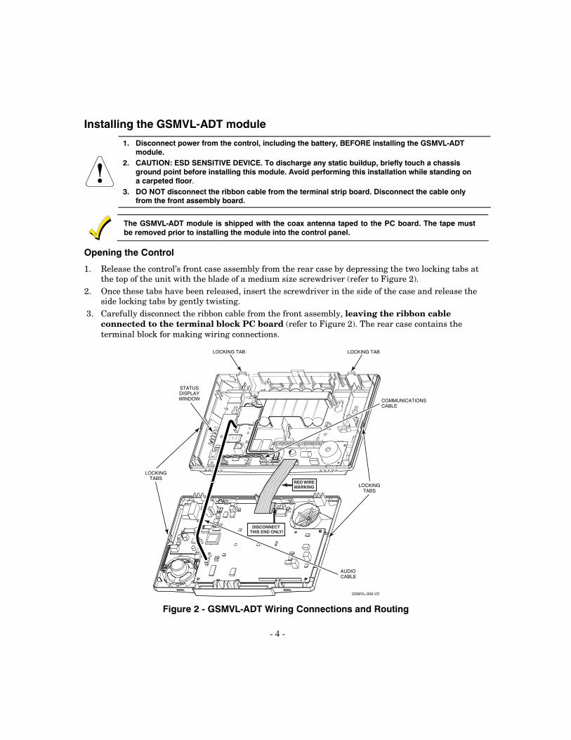
Installing the GSMVL-ADT Module and Antenna
1. Remove the tape that secures the coax cable to the GSMVL-ADT PC board. 2. Install the GSMVL-ADT module into the control’s back plate and secure it with the three provided
screws. Refer to Figure 3. 3. Connect the provided communications cable between the GSMVL-ADT module and the PC board.
This cable provides DC power and ground for the module and ECP connections. COMMUNICATIONSCABLE
GSMVL-ADT
SCREW (3)
GSMVL-009-V1
Figure 3 – Mounting the GSMVL-ADT Module 4. Route the antenna cable as shown in Figure 4. Use the supplied nylon tie wrap to secure the cable to
the strain relief point as shown. Note that the antenna itself is passed through the back of the unit, to be placed into the wall cavity behind the unit during final installation.
The coax cable must be routed as shown in Figure 4.
5. Connect the antenna cable to the matching cable on the GSMVL-ADT module as shown in Figure 4. 6. Install the provided IC label (P/N K15008) on the control’s back case as shown in Figure 5.

- 6 -
GSMVL-010-V0
TIE WRAPCABLE
CONNECTION
ANTENNA
COAX CABLE
Figure 4 – Mounting the GSMVL-ADT Antenna
FCC ID: CFS8DLLYNXREN-6IC: 573F-LYNXREN6THIS DEVICE COMPLIES WITH PART 15 OF FCC RULES AND RSS 210 OFINDUSTRY CANADA. OPERATION IS SUBJECT TO THE FOLLOWING TWOCONDITIONS: (1) THIS DEVICE MAY NOT CAUSE HARMFUL INTERFERENCE,AND (2) THIS DEVICE MUST ACCEPT ANY INTERFERENCE RECEIVED,INCLUDING INTERFERENCE THAT MAY CAUSE UNDESIRED OPERATION.
K14118-8 12/07 Rev A
LYNXR-I SERIES
COMPLIES WITH FCC RULES, PART 68FCC REGISTRATION NO.: 5GBUSA-25623-AL-ERINGER EQUIVALENCE: 0.6B
IC MODEL: LYNXREN-6
07000-018-V0
K15008 1/08 Rev A
CONTAINS TRANSMITTER MODULE IC: 267W-MC56
IC MODEL: LYNXREN-7
FCC ID: QIPMC56
Figure 5 – IC Label location

- 7 -
7. Make the wiring connections (power, telephone if used, etc.) to the unit in accordance with the ADT QuickConnect Installation Instructions.
8. Place the antenna into the wall cavity behind the unit’s mounting location and allow it to hang on the inside of the wall.
9. Physically mount the unit to the wall in accordance with the ADT QuickConnect Installation Instructions.
10. After the wiring connections are complete, carefully reconnect the ribbon cable to the control front case circuit board connector (properly aligning the red wire).
11. Connect the provided shielded audio cable between the GSMVL-ADT moducle and the control’s PC board as shown in Figure 2.
12. Program the GSMVL-ADT. Refer to the Programming the GSMVL-ADT Module section.
13. Snap the control front assembly to the back plate.
Programming the GSMVL-ADT Module The GSMVL-ADT Module can be programmed through the following methods:
• The AlarmNet Direct website
• Use of a 7720P Programming Tool
Using the AlarmNet Direct website To program the module via the website (if you are already signed up for this service), go to: https://services.alarmnet.com/AlarmNetDirect/userlogin.aspx
If you are not signed up for this service, click on “Dealer Sign-Up”. Log in and follow the on-screen prompts. Please have the following information available when programming the module: 1. CS1 IP Address (12-digit number) 2. CS1 Port (0-65535) 3. Access Point Name (APN 1) (roch, aurora, kc) 4. CS2 IP Address (12-digit number) 5. CS2 Port (0-65535) 6. Access Point Name (APN 2) (roch, aurora, kc) 7. Primary Subsystem Number (two-digit number) 8. Primary Group Number (three-digit number) 9. Primary Subscriber ID (four-digit number) 10. After programming is complete, you must transfer the data to the GSMVL-ADT.
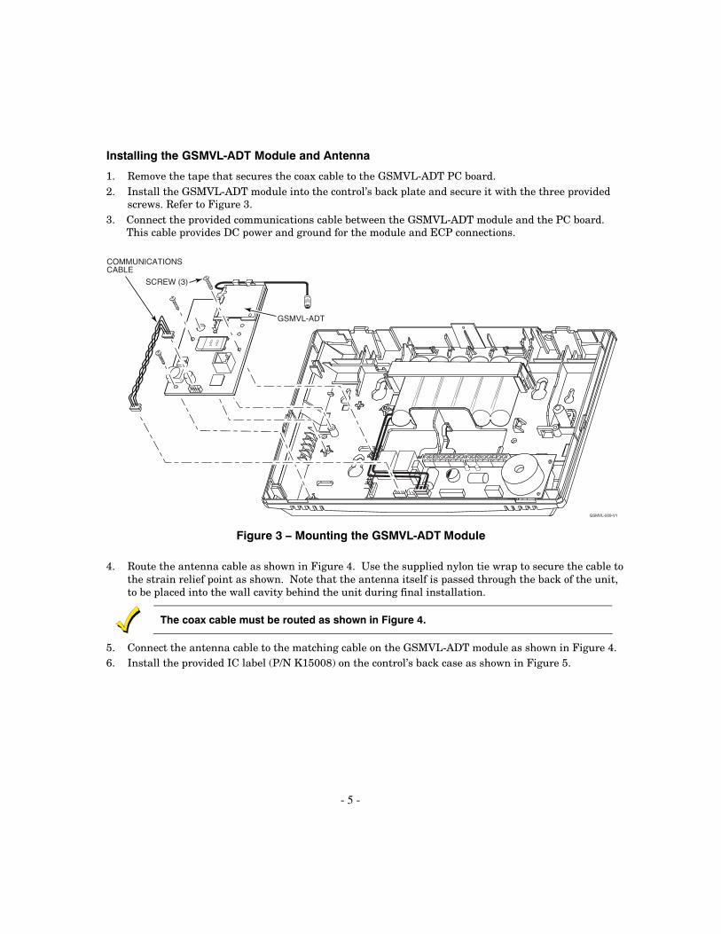
Using a 7720P Programming Tool Connect the 7720P Programming Tool as shown in Figure 6. The GSMVL-ADT powers the 7720P Programming Tool via the programming jack.
Each key of the 7720P has two possible functions: a normal function and a Shift function. • To perform a normal key function, simply press the desired key. • To perform a Shift function, press the [shift] key, and then press the appropriate key.
- 8 -
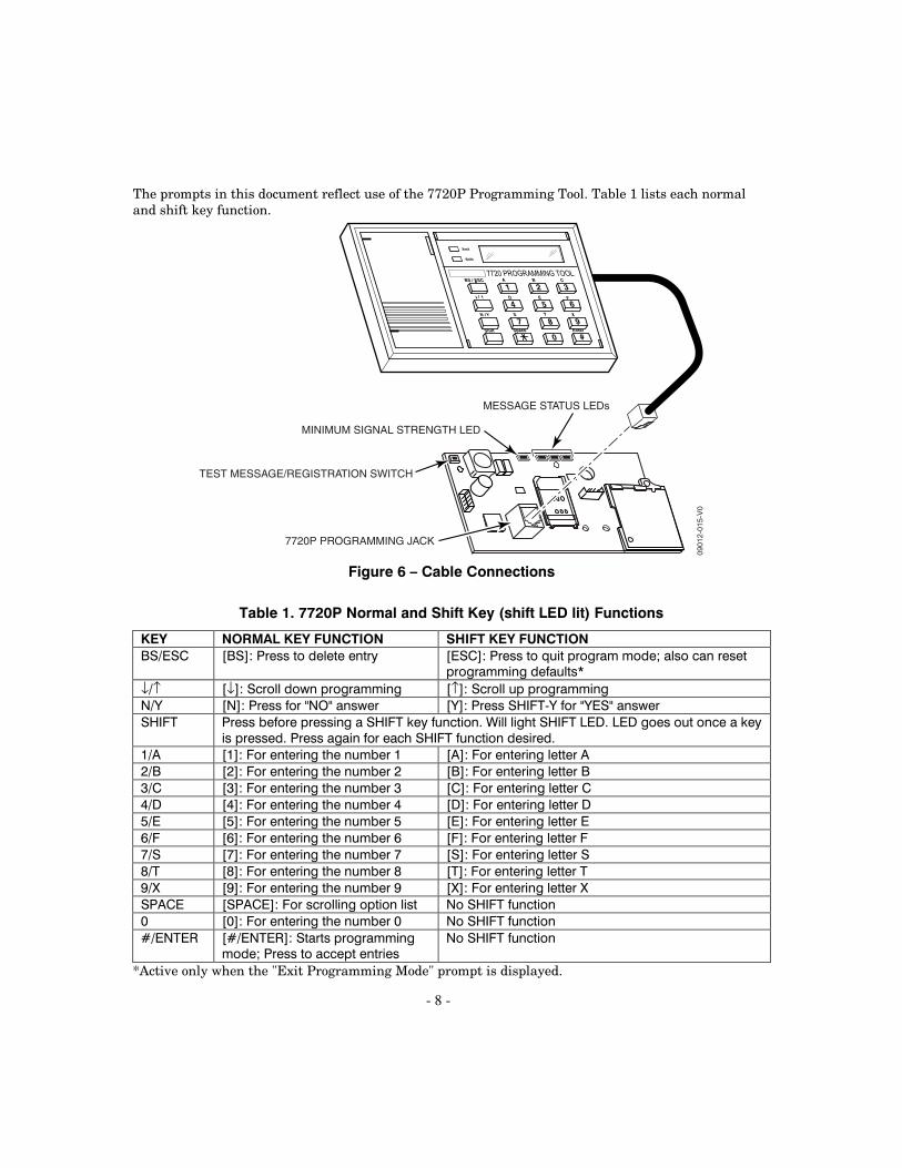
The prompts in this document reflect use of the 7720P Programming Tool. Table 1 lists each normal and shift key function.
7720P PROGRAMMING JACK
MESSAGE STATUS LEDs
MINIMUM SIGNAL STRENGTH LED
TEST MESSAGE/REGISTRATION SWITCH
0901
2-01
5-V
0
A B C
D E F
S T X
Xmit
Shift
Space EnterShift
N / Y
BS / ESC
/
7720 PROGRAMMING TOOL
#0
1 2 3
4 5 6
987
Figure 6 – Cable Connections
Table 1. 7720P Normal and Shift Key (shift LED lit) Functions
KEY NORMAL KEY FUNCTION SHIFT KEY FUNCTION BS/ESC [BS]: Press to delete entry [ESC]: Press to quit program mode; also can reset
programming defaults* ↓/↑ [↓]: Scroll down programming [↑]: Scroll up programming N/Y [N]: Press for "NO" answer [Y]: Press SHIFT-Y for "YES" answer SHIFT Press before pressing a SHIFT key function. Will light SHIFT LED. LED goes out once a key
is pressed. Press again for each SHIFT function desired. 1/A [1]: For entering the number 1 [A]: For entering letter A 2/B [2]: For entering the number 2 [B]: For entering letter B 3/C [3]: For entering the number 3 [C]: For entering letter C 4/D [4]: For entering the number 4 [D]: For entering letter D 5/E [5]: For entering the number 5 [E]: For entering letter E 6/F [6]: For entering the number 6 [F]: For entering letter F 7/S [7]: For entering the number 7 [S]: For entering letter S 8/T [8]: For entering the number 8 [T]: For entering letter T 9/X [9]: For entering the number 9 [X]: For entering letter X SPACE [SPACE]: For scrolling option list No SHIFT function 0 [0]: For entering the number 0 No SHIFT function #/ENTER [#/ENTER]: Starts programming
mode; Press to accept entries No SHIFT function
*Active only when the "Exit Programming Mode" prompt is displayed.

- 9 -
Programming Conventions Programming is accomplished by answering a series of prompts (questions). Most prompts require only a [Y]es or [N]o response, while others require a numerical response (ID numbers, etc.). The current value is displayed on the second line in parentheses ( ). A "?" indicates an invalid entry. Use the [ENTER] key to accept the current entry and proceed to the next prompt. If the entered value is invalid, pressing [ENTER] re-displays the prompt; the next prompt is not displayed until a valid answer is entered. Use the up/down arrow keys to scroll through the programming questions without changing any values. Press the [ESC] key to go to the end of the list of questions.
PROGRAMMING THE DEVICE Refer to Table 2 for GSMVL-ADT programming and follow the prompts. Press the [ENTER] key to begin programming.
NOTE: The ADT monitoring center can remotely block access to local device
programming. If this has been done, the following prompt appears:
Access to Prog Mode Denied
Table 2. Programming the GSMVL-ADT Module.
NOTE: The default programming values are listed in the prompts below.
PROMPTS ENTRY OPTIONS DESCRIPTION
1
Strt Prog Mode? (Y/N)_
[Y], [N] Enters programming mode.
2
Enter Password
[0-9, A-F, N, S, T, X, Y]
If a password has been previously assigned, this prompt appears. Enter a 4-digit password (0-9, A-F, N, S, T, X, Y). The next prompt appears.
3
Program Device? (Y/N)_
[Y], [N] To begin programming the module, press [Y] and go to Prompt 9: "Device Mode." To create a password if none has been assigned, press [N] and go to Prompt 4: "Create Password?." To change an existing password, press [N] and go to Prompt 5: "Change Password?."
4 Create Password? (Y/N)_
[Y], [N] Passwords can be used to protect account and programming information. If no password has been assigned, this prompt appears after pressing [N] at the "Program Device?" prompt. If a password is desired, press [Y] and go to Prompt 6: "Enter Password."

- 10 -
PROMPTS ENTRY OPTIONS DESCRIPTION
5 Change Password? (Y/N)_
[Y], [N] If a password has already been assigned, this prompt appears after pressing [N] at the "Program Device?" prompt. Press [Y] if you want to change the password. NOTE: To clear an existing password, without
entering a new one, answer [Y] to the "Change Password?" prompt, then press the [Enter] key when prompted for the new password and its confirmation.
6 Enter Password
[0-9, A-F, N, S, T, X, Y]
This prompt is displayed if [Y] was pressed in Prompt 4 or 5. Enter a 4-digit password (0-9, A-F, N, S, T, X, Y). Re-enter the password as confirmation. If the password doesn't match the first entry, the following is displayed followed by the "Exit Prog. Mode?" prompt:
7 Verify Password
[0-9, A-F, N, S, T, X, Y]
Verify Not OK PSWD not created
Otherwise, the "Exit Prog. Mode?" prompt is displayed directly.
8 Exit Prog. Mode? (Y/N)_
[Y], [N]
[ESC]
Exits program mode. Press [N] to go back to Prompt 3. Press [ESC] to load factory defaults. Refer to the Exiting Programming Mode paragraph in this section.
9
Device Mode (ECP)_
• ECP • 4204 Emu • Two 4204s
Press the [space] key to scroll through the modes of operation. Press [ENTER] to select ECP mode. IMPORTANT NOTE: Do not select any other mode.
1. Account information is provided by the central station administrator. 2. The ADT QuickConnect controls do not support second account reporting.
PROMPTS ENTRY OPTIONS DESCRIPTION
10 CS1 IP 255.255.255.255_
12-digit IP Address: xxx xxx xxx xxx
Enter the 4-part primary CS IP address of the receiver at the reporting center to which this device will report. The four parts of the address must be separated by spaces. This entry CANNOT be left as "255.255.255.255". It MUST be programmed with a valid IP address.
11 CS1 Port (443)_
[0-65535] Enter the internet port of the first CS receiver that the device will report to.

- 11 -
PROMPTS ENTRY OPTIONS DESCRIPTION
12 CS2 IP 255.255.255.255_
12-digit IP Address: xxx xxx xxx xxx
Enter the 4-part secondary CS IP address of the receiver at the reporting center to which this device will report. The four parts of the address must be separated by spaces. This entry CANNOT be left as "255.255.255.255". It MUST be programmed with a valid IP address.
13 CS2 Port (443)_
[0-65535] Enter the internet port of the second CS receiver that the device will report to.
14 APN 1 roch_
• roch • aurora • kc
Press the [space] key to scroll through the available Access Point Names (APN's). Press [ENTER] to select the Primary APN assigned for this installation.
15 APN 2 aurora_
• roch • aurora • kc
Press the [space] key to scroll through the available Access Point Names (APN's). Press [ENTER] to select the Secondary APN assigned for this installation.
16 Primary Subsys # (??)_
[00-99] Enter the primary subsystem this unit is a member of.
17 Primary Group # (???)_
[000-999] Enter the primary group number this unit is a member of.
18 Primary Sub ID (????)_
[0001-9999] Enter the 4-digit subscriber account number for the primary central station, 0001-9999.
19
En. 2nd CS Y/N (N)_
[Y], [N] Applicable only if control supports Central Station #1 and #2 Category Enable reporting for the LRR device. Used if reporting to a second central station is desired. If [N], go to Prompt 23: "Device Address." Note: Must be [N] for QuickConnect
20
2ndary Subsys # (??)_
[00-99] Enter the secondary subsystem for this unit.
21 2ndary Group #
(???)_
[000-999] Enter the secondary group number for this unit.
22 2nd Sub ID
(????)_
[0001-9999] Enter the 4-digit secondary subscriber account number, 0001-9999.

- 12 -
PROMPTS ENTRY OPTIONS DESCRIPTION
23
Device Address (03)_
[01-30]
The GSMVL-ADT communicates with the panel as a Long Range Radio (LRR) device. Enter ECP device address 03. NOTE: When programming the control, enable the
LRR output.
24
Supervision (24 Hours)_
• 30 Day • 24 Hour • None
The GSMVL-ADT will send one status message in the programmed interval. When the Central Station Receiver receives this message, it will generate a periodic RF transmission (E603) and pass this message to the automation system. It is the responsibility of the automation system to alert the CS when that message is failed to be delivered. Press the [space] key to scroll through choices. UL NOTE: Must be 24 hour.
25
Old Alarm Time (10 Minutes)_
• 10 Minutes• 15 Minutes• 30 Minutes• 1 Hour• 2 Hours • 4 Hours • 8 Hours • 12 Hours • 24 Hours
The old alarm time sets how long an undeliverable alarm is retried for delivery to the central station. If the message is not validated, it is retried until the old alarm time is reached or the message is validated. Press the [space] key to scroll through choices. UL NOTE: Must be 10 minutes.
26
GSM Flt Time (00 mins)_
[00-99] [00] = panel is NOT notified
In the event the module detects a communication path failure, enter the time delay (in minutes) before the module notifies the control panel with a trouble message. The control panel can then notify the central station. Enter 00 if you do not want this module to notify the control panel of a communication path failure. UL NOTE: Must be one (01) minute.
27
Review? Y/N
[Y] = review [N] = exit
Reviewing Programming Mode Entries To review the programming options (to ensure that the correct entries have been made), press [Y]. The programming prompts are displayed again. Use the up/down arrow keys to scroll through the program fields without changing any of the values. If a value requires change, simply type in the correct value. When the last field is displayed, the “REVIEW?” prompt again appears. To exit the programming mode, press [N] in response to the "REVIEW?" prompt, and refer to Exiting Programming Mode paragraph at the end of this section.

- 13 -
ECP Status Codes The control will display “FAULT 103” if any of the events listed below should occur. In addition, the Contact ID codes (listed in Appendix A) for these conditions are sent to the central station by the module.
• The Control panel loses communication with GSMVL-ADT. • The GSMVL-ADT is not programmed. • The GSMVL-ADT loses GSM network connectivity (if GSM Fault Time is not set to 0).
Exiting Programming Mode To exit the programming mode, press [N] in response to the "REVIEW?" question. Then press [Y] to the "Exit Prog Mode?" question. Upon exiting, the message “Checking Root File TX Path” will be displayed, and the configuration file at the server is updated to log the changes made. When complete, the message "DONE" is displayed to indicate the file was successfully uploaded.
If critical configuration changes were made, such as the mode of operation, the GSMVL-ADT will reset to ensure that the programming features are enabled.
If the file is not successfully uploaded, one of the following prompts will be displayed. Follow the steps shown below, until the upload is successful.
Display Description What to do
Cannot Upload Try Again? Y/N_
GSMVL-ADT radio not yet initialized.
Wait for RSSI LEDs to be lit. Press [Y].
Failed to Update Root File!
Network problem, or you answered "N" to "Cannot Upload Try Again?" prompt.
Initiate the Force Server Update command by pressing the [0] key; refer to the Programmer Keyboard Commands section.
Setting Factory Defaults To reset the programming options to factory-default values, press [ESC] at the "Exit Prog Mode?" prompt.
Set Default? Y/N_
Press [Y] to reset factory default values.
Press [N] to cancel this function.
If you press [Y], all programmed values are reset to the original factory settings.
PLEASE NOTE THAT THIS WILL ERASE ANY PASSWORD THAT MAY HAVE BEEN ENTERED. After pressing [Y], the Create Password prompt appears (see Programming step 4).

- 14 -
DOWNLOAD CONFIGURATION FILE
Force Download of Configuration File Once you have programmed the GSMVL-ADT via the AlarmNet Direct website, the Configuration File must be downloaded to enable the account. A GSMVL-ADT that has not been configured is indicated on the Status Display as: Status lit, Message slow blinking, and Fault not lit. The LEDs can be viewed through the status window on the left side of the QuickConnect control panel.
GSMVL-005-V0
FAULT, RED
MESSAGE, YELLOW
STATUS, GREEN
Figure 7 - Unconfigured GSMVL-ADT Status Display in Normal Operation
Throughout this document, the following key is used to describe LED state:
ONGSM-002-V0
OFF FAST BLINK SLOW BLINK
Figure 8 - LED Key You can download the configuration file to the GSMVL-ADT by one of the following methods: Initiate the configuration download sequence by one of the following methods:
1. Click the GSMVL-ADT Test Message/Registration Switch three times.
OR
2. Enter the Installer Code + OFF at the QuickConnect keypad.
OR
3. Press the [↑] key on the 7720P Programming Tool. (Refer to Using the Programming Tool)
You can monitor the download process by viewing the GSMVL-ADT Status Display on the side of the QuickConnect Control Panel. The Message (yellow) LED and the Status (green) LED will blink slowly in unison while the configuration download is in progress. If the retrieval has been completed successfully, the GSMVL-ADT will reset and enter normal operating mode; the Status (green) LED goes out and the Message (yellow) LED is lit to indicate that the power-on / reset message is waiting to be sent. This message will appear at the receiving station as “E339 803”. The description may read “Trouble – Exp. Mod. Reset”.

- 15 -
Using the Programming Tool The installer can configure the GSMVL-ADT through a series of keyboard commands on the 7720P Programming Tool.
Once the installation is complete, initiate the configuration download process pressing the [↑] key on the 7720P the programming tool. The following screen will be displayed:
Getting Config file
When the configuration download is complete, the GSMVL-ADT will reset and the screen on the 7720P will go blank.
If the GSMVL-ADT failed the download process, the following screen will be displayed:
Could not get Config data!

- 16 -
PROGRAMMER KEYBOARD COMMANDS Programmer keyboard commands can be used to view connectivity settings and options. Most commands require you to press the [shift] key and then the designated command key. (See the keys designated in red on the 7720P Programming Tool.)
Programmer Notes:
1. While viewing settings and options, use the [space] key to cycle to the next display in the series (shown as boxed sections.) Use [backspace] to cycle to the previous display in the series.
2. The 7720P will not operate if the power line voltage is removed.
Status Display Description [A]
7845GSMADT x.x.xx mm/dd/yy
Software Revision "x.x.xx" indicates the installed software revision. mm/dd/yy indicates month, day and year of the revision.
Module Identification Displays
Status Display Description [B]
MAC xxxxxxxxxxxx MAC CRC yyyy
MAC Address “xxxxxxxxxxxx” indicates the GSMVL-ADT's unique identification number. "yyyy" indicates the MAC CRC number. These numbers are found on the label on the module, as well as the label on the box.Press the [space] key to go to the next field. Press the [backspace] key to go to the previous field.
SCID xxxxx xxxxx xxxxx xxxxx
SCID Display Displays the identification number assigned to the SIM card (SCID) in this device. Press the [space] key to go to the next field. Press the [backspace] key to go to the previous field.
IMEI xxxxxxxx xxxxxx x
IMEI Display Displays the identification number assigned to the GSMVL-ADT module in this device. Press the [space] key to get the MAC Address. Press the [backspace] key to go to the previous field.
[C]
Mon 01 Jan 2001 05:48:39 am
Time Retrieves the current date and time from the AlarmNet network in Greenwich Mean Time (GMT). This display confirms that the module is in sync with network.
[D]
Encryption Test AES Passed!
Encryption Test Performs a test of the AES encryption the GSMVL-ADT uses to send messages to the ADT Network. Press the [Space] key to go to the next field. Press the backspace [BS] key to go to the previous field.
- 17 -
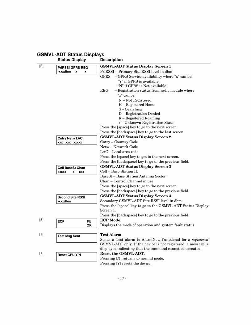
GSMVL-ADT Status Displays Status Display Description [E]
PriRSSI GPRS REG -xxxdbm x x
GSMVL-ADT Status Display Screen 1 PriRSSI – Primary Site RSSI level in dbm GPRS – GPRS Service availability where “x” can be: “Y” if GPRS is available “N” if GPRS is Not available REG – Registration status from radio module where “x” can be: N – Not Registered H – Registered Home S – Searching D – Registration Denied R – Registered Roaming ? – Unknown Registration State Press the [space] key to go to the next screen. Press the [backspace] key to go to the last screen.
Cntry Netw LAC xxx xxx xxxxx
GSMVL-ADT Status Display Screen 2 Cntry – Country Code Netw – Network Code LAC – Local area code Press the [space] key to get to the next screen. Press the [backspace] key to go to the previous field.
Cell BaseSt Chan xxxxx x xxx
GSMVL-ADT Status Display Screen 3 Cell – Base Station ID BaseSt – Base Station Antenna Sector Chan – Control Channel in use Press the [space] key to go to the next screen. Press the [backspace] key to go to the previous field.
Second Site RSSI -xxxdbm
GSMVL-ADT Status Display Screen 4 Secondary GSMVL-ADT Site RSSI level in dbm. Press the [space] key to go to the GSMVL-ADT Status Display Screen 1. Press the [backspace] key to go to the previous field.
[S]
ECP Flt OK
ECP Mode Displays the mode of operation and system fault status.
[T]
Test Msg Sent
Test Alarm Sends a Test alarm to AlarmNet. Functional for a registered GSMVL-ADT only. If the device is not registered, a message is displayed indicating that the command cannot be executed.
[X]
Reset CPU Y/N
Reset the GSMVL-ADT. Pressing [N] returns to normal mode. Pressing [Y] resets the device.

- 18 -
Status Display Description
[↑] (UP arrow)
Getting Config File
Force Download of Configuration File from Server Forces the device to retrieve its programming parameters from the server. Force Upload of Configuration File to Server Pressing [Y] will force the device to upload its entire configuration file to the server. Pressing [N] cancels the operation. NOTE: If the GSMVL-ADT module is not initialized when you enter this
command, the following screen will be displayed:
Cannot Upload Try Later! _
[0]
Force Server Update? Y/N
Wait for the RSSI LEDs to light, indicating the GSMVL-ADT module has completed its initialization, and try again.
[ENTER]
Strt Prog Mode?
Y/N_
Enter Program Mode Press [Y] to enter program mode; otherwise, press [N].
SUMMARY OF LED OPERATION
GSMVL-ADT Status Display Operation The GSMVL-ADT Status Display has four LEDs used to indicate message and device status (refer to Figure 9). When installed in the control, the LEDs can be viewed through the status window in the side of the control panel and appear in the following order, from top to bottom. • STATUS, green • MESSAGE, yellow • FAULT, red • MINIMUM SIGNAL STRENGTH, green
Each LED can have four different states - ON, OFF, FAST BLINK and SLOW BLINK. Throughout this document, the key shown in Figure 4 is used to describe LED state:
ONGSMVL-002-V0
OFF FAST BLINK SLOW BLINK
Figure 9 - LED Key

- 19 -
Minimum Signal Strength LED Operation The Minimum Signal Strength LED normally displays the module’s signal strength. The LED (green LED) will be lit to indicate that the minimum required signal strength for installation exists between the module and the receiving tower. Refer to Figure 10.
Table 3. Status and Signal Strength LED Operation LED COLOR LED DESCRIPTION GREEN STATUS ON – GSMVL-ADT is NOT programmed.
OFF – GSMVL-ADT is programmed. FAST BLINK – Download session with Compass in progress. SLOW BLINK – In unison with yellow LED – Configuration Download in progress.
YELLOW MESSAGE ON – Message transmission pending. QUICK PERIODIC BLINK - Normal FAST BLINK – Message waiting for network ACK. SLOW BLINK – In unison with green LED – Configuration Download in progress.
RED FAULT ON – No contact with network. OFF– Normal. SLOW BLINK – Loss of communication with the panel (ECP fault). FAST BLINK – No network contact AND loss of communication with the panel.
GREEN MINIMUM
SIGNAL STRENGTH
ON – Minimum required signal strength is present. BLINKING – Marginal signal strength is present. OFF– Installation is not recommended.
ALL (of the above) FAST BLINK – Hardware Error. Call the Technical Assistance Center.
FAULT, RED
MESSAGE, YELLOW
STATUS, GREEN
GSMVL-003-V0
A
FAULT, RED
MESSAGE, YELLOW
STATUS, GREEN
B
Figure 10 - A Configured GSMVL-ADT Status Display (A) and an Unconfigured GSMVL-ADT Status Display in Normal Operating State (B)

- 20 -
CENTRAL STATION MESSAGES The following messages are sent to the Central Station by the GSMVL-ADT module for the conditions listed below.
Table 4. GSMVL-ADT Central Station Messages
Alarm Condition ECP Mode Alarm Code
ECP Mode Restore Code
Power On Reset E339 C0803 ECP Supervision E355 C0000 R355 C0000 Communication Path Restore R350 C0951 Test 5555 5555 9
Note: The control panel sends its own general code (E353) for a trouble condition.
GSMVL-ADT DOWNLOADING
General Information The GSMVL-ADT can be used to provide high-speed up/downloading to ADT QuickConnect control panels over the GPRS network via ECP communication. This allows site maintenance independent of central station monitoring, and modification to sites globally.
UUUULLLL Downloading may only be performed if a technician is at the site.

- 21 -
GLOSSARY
AES – Advanced Encryption Standard, also known as Rijndael, is a 256-bit block cipher adopted as an encryption standard by the U.S. government, and used in applications requiring an extremely robust level of security.
ECP – Enhanced Console Protocol, which is a proprietary communications bus used in ADT and Honeywell VISTA control panels for wiring additional keypads and peripheral devices; consists of a four-wire data bus (power + / -, data in/out).
GPRS – (General Packet Radio Service)
GSM – Global System for Mobile communications, which is an international standard for digital mobile phone systems used for cellular communication.
IMEI – International Mobile Equipment Identity number
IP Address – A unique number consisting of four parts separated by periods, sometimes called a "dotted quad.," for example: 204.17.29.11, assigned to every computer/workstation connected to the Internet. IP numbers can be "static" (assigned and unchanging) or "dynamic," assigned via DHCP at each and every startup.
MAC Address – Media Access Code; unique ID code associated with each device, and located on the digital communicator module label.
Subnet Mask - A Subnet is a portion of a network that shares a network address with other portions of the network, and is distinguished by a subnet number. The Subnet Mask is a 32-bit address mask used in IP to indicate the bits of an IP address that are being used for the subnet address.
TCP/IP – Transmission Control Protocol / Internet protocol

- 22 -
SPECIFICATIONS 1. Physical
Dimensions: 5.625" x 2.25"
2. Electrical Input Voltage: 12 VDC (powered by the ADT QuickConnect control) (Range: 5.5 VDC-12 VDC)
Quiescent Current: 40mA Peak Current During Transmit: 650mA

- 23 -
NOTES

ADT Security Services, Inc. One Town Center Road Boca Raton, FL 33486
Copyright © 2008
ÊK14936-1V1)Š K14936-1V1 2/09 Rev. A