Embed Size (px)
Citation preview
Service Manual 73
Installation and Service Instructions
GlobalGear Series Pumps
Service Manual 73
Page 2 of 32
Table of Contents Introduction Page 2 General Description/Pumping Principle Page 3 Modular Design Page 3 GlobalGear Models Page 4 Installation Page 5 Simple Efficiency Improvement Page 6 Packing Adjustment Page 6 Lubrication Requirements Page 7
Recommended Lubricants Page 7 Parts Interchangeability Page 8 Inspection / Repair Page 9 Pump Disassembly - Partial Page 9 Drive Module Remova ; Page 10 Drive Module Installation Page 11 Cover / Idler Gear Installation Page 12 Relief Valve Installation Page 12 In-Line Seal / Packing Replacement Page 13 Torque requirements-Mounting hardware Page 13 Pump Disassembly – Complete Page 17 Pump Assembly Page 20
Idler Bushing Installation Page 20 Bracket Bushing Installation Page 21 Packing Installation Page 22 In-Board Mechanical Seal Installation Page 23 Out-Board Mechanical Seal Installation Page 23 Drive Module Rebuild / Installation Page 25 Cover / Idler Gear Installation Page 26 Relief Valve Installation Page 26 End Clearance Adjustment Page 27
Relief Valve Disassembly Page 29 Relief Valve Assembly Page 29 Pressure Adjustment of Relief Valve Page 29 Troubleshooting Page 30 Material Returns Page 32 Introduction The GG Series pumps have been designed and manufactured to provide years of service under normal operating conditions. Illustrations used in this manual are for reference purposes only. Consult the factory or an authorized Tuthill distributor for proper part identification. When ordering replacement parts, provide as much detail as possible to ensure correct parts are provided. Details should include the full model number (18 digits), serial number, name of part, part number (if known) and part material. Service Manual # 73 for the GG Series pumps is available at www.tuthillpump.com
Service Manual 73
Page 3 of 32
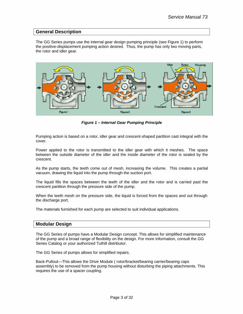
General Description The GG Series pumps use the internal gear design pumping principle (see Figure 1) to perform the positive-displacement pumping action desired. Thus, the pump has only two moving parts, the rotor and idler gear.
Figure 1 – Internal Gear Pumping Principle Pumping action is based on a rotor, idler gear and crescent-shaped partition cast integral with the cover. Power applied to the rotor is transmitted to the idler gear with which it meshes. The space between the outside diameter of the idler and the inside diameter of the rotor is sealed by the crescent. As the pump starts, the teeth come out of mesh, increasing the volume. This creates a partial vacuum, drawing the liquid into the pump through the suction port. The liquid fills the spaces between the teeth of the idler and the rotor and is carried past the crescent partition through the pressure side of the pump. When the teeth mesh on the pressure side, the liquid is forced from the spaces and out through the discharge port. The materials furnished for each pump are selected to suit individual applications. Modular Design The GG Series of pumps have a Modular Design concept. This allows for simplified maintenance of the pump and a broad range of flexibility on the design. For more information, consult the GG Series Catalog or your authorized Tuthill distributor. The GG Series of pumps allows for simplified repairs. Back-Pullout—This allows the Drive Module ( rotor/bracket/bearing carrier/bearing caps assembly) to be removed from the pump housing without disturbing the piping attachments. This requires the use of a spacer coupling.
Service Manual 73
Page 4 of 32
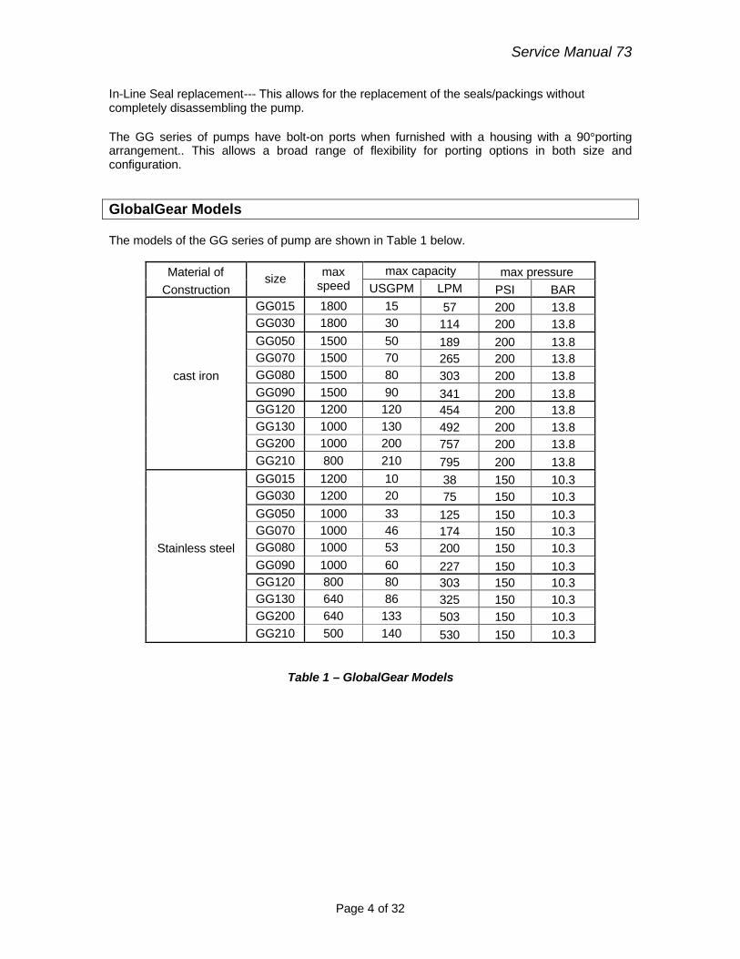
In-Line Seal replacement--- This allows for the replacement of the seals/packings without completely disassembling the pump. The GG series of pumps have bolt-on ports when furnished with a housing with a 90°porting arrangement.. This allows a broad range of flexibility for porting options in both size and configuration. GlobalGear Models The models of the GG series of pump are shown in Table 1 below.
Material of max capacity max pressure
Construction size max
speed USGPM LPM PSI BAR GG015 1800 15 57 200 13.8 GG030 1800 30 114 200 13.8 GG050 1500 50 189 200 13.8 GG070 1500 70 265 200 13.8
cast iron GG080 1500 80 303 200 13.8 GG090 1500 90 341 200 13.8 GG120 1200 120 454 200 13.8 GG130 1000 130 492 200 13.8 GG200 1000 200 757 200 13.8 GG210 800 210 795 200 13.8 GG015 1200 10 38 150 10.3 GG030 1200 20 75 150 10.3 GG050 1000 33 125 150 10.3 GG070 1000 46 174 150 10.3
Stainless steel GG080 1000 53 200 150 10.3 GG090 1000 60 227 150 10.3 GG120 800 80 303 150 10.3 GG130 640 86 325 150 10.3 GG200 640 133 503 150 10.3 GG210 500 140 530 150 10.3
Table 1 – GlobalGear Models
Service Manual 73
Page 5 of 32
! WARNING
Failure to follow these instructions could result in serious bodily injury or death. Do not attempt to work on any Tuthill pump installation before completing the steps below. Disconnect the drive so that it cannot be started while work is being performed. Review the Material Safety Data Sheet (MSDS) applicable to the liquid being pumped to determine its characteristics and the precautions necessary to ensure safe handling. Vent all pressure within the pump through the suction or discharge lines. All Tuthill pumps contain residual hydraulic oil from the factory production test. Determine if this is compatible with the fluid you are pumping. If the fluid is incompatible, then the pump must be fully flushed prior to use. If the pump is to be operated at elevated temperatures, the pump should be brought up to operating temperatures gradually. Rapid or sudden introduction of liquids at elevated temperatures into the cold liquid chamber of the pump could cause damage to pump externals, seals or other internal parts. Do not run the pump dry. Failure to comply with this could cause severe damage to the internal seal, bushings and/or metal parts. Installation For optimum pump performance the suction line must be at least as large as the corresponding pump port. It should be as short as possible in order to avoid excessive pressure drops and must be airtight. Locate the pump as close to the source of supply as conditions permit and if possible, below the level of the liquid in the reservoir. When necessary to locate the pump in a pit, provisions should be made to safeguard against flooding. When handling high viscosity liquids, the speed of the pump must be reduced and the size of the inlet lines increased to prevent cavitation. Refer to the NPSHr data for the pump. The GlobalGear series of pumps provides a orifice vent to the seal chamber in the bracket from one of the housing’s ports ( typically the suction port). On applications where the viscosity is 7500 SSU or greater, the orifice plug should be removed so there is no restriction on the vent hole. Pumps should be filled with liquid at installation and should never be allowed to run dry. The placement of a strainer on the suction side of the pump will restrict any solids or abrasives from entering the pump, which could cause internal damage. Under no conditions should the pump be used to support external piping loads (weight or expansion). Piping and other equipment should be independently supported. Piping strain can result in misalignment, hot bearings, worn couplings, vibration, etc. It is important that the piping used be clean and free of chips and scales. The discharge line must be designed with the maximum pressure rating of the pump in mind. Excessive pressure could cause damage to your motor and/or pump. If a pressure relief valve
Service Manual 73
Page 6 of 32
has not been supplied with the pump, some other means of pressure protection must be utilized. This could include in-line safety valves, pressure shutdown switches or other similar devices. Pumps shipped from the factory with relief valves have the relief valve set at full by-pass at the factory on 150SSU oil at our factory production test speeds. Field adjustments will be required to meet the actual application requirements. Pumps shipped from the factory with relief valves are assembled for clockwise or counterclockwise rotation as originally specified. If you want to change rotation, the relief valve assembly must be removed and turned 180 degrees. The adjusting screw must always point toward the suction line. Every pump installation should have a good foundation. Its structure should be sufficiently strong to hold the pump rigid and to absorb any strain or shock that may be encountered. The installation should be leveled, checked for proper piping alignment, and then fastened securely. The alignment should be rechecked after the pump’s temperature has reached it’s operating temperature. Direct drive through a traditional flexible coupling is recommended. However, do not expect the coupling to compensate for misalignment. Contact the coupling manufacturer to determine the maximum amount of misalignment that the coupling can be subjected to. Never operate the pumps without all the guards in place. Pumps operating with bi-directional rotation must have pressure relief devices installed on both sides of the pump. Simple Efficiency Improvement The efficiency of the pump may decrease after considerable use as a result of wear. If performance deteriorates below acceptable levels, it may be moderately improved by reducing the end clearance between rotating elements. Refer to the appropriate reassembly instruction to accomplish this task. If this does not improve performance to an acceptable level, then further repair work may be necessary. Packing Adjustment
! WARNING Packing is designed to leak. Therefore, when pumping hazardous liquids, a mechanical seal is recommended to minimize any potential source of leakage that could result in a hazardous condition. Pumps with packing will require periodic adjustment. To accomplish this, gently and evenly tighten the packing gland nuts, which will further compress the packing.
Service Manual 73
Page 7 of 32
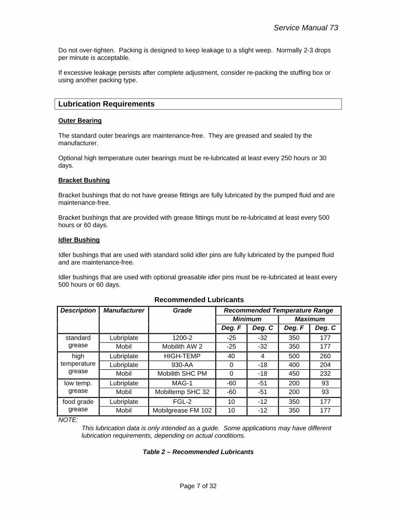
Do not over-tighten. Packing is designed to keep leakage to a slight weep. Normally 2-3 drops per minute is acceptable. If excessive leakage persists after complete adjustment, consider re-packing the stuffing box or using another packing type. Lubrication Requirements Outer Bearing The standard outer bearings are maintenance-free. They are greased and sealed by the manufacturer. Optional high temperature outer bearings must be re-lubricated at least every 250 hours or 30 days. Bracket Bushing Bracket bushings that do not have grease fittings are fully lubricated by the pumped fluid and are maintenance-free. Bracket bushings that are provided with grease fittings must be re-lubricated at least every 500 hours or 60 days. Idler Bushing Idler bushings that are used with standard solid idler pins are fully lubricated by the pumped fluid and are maintenance-free. Idler bushings that are used with optional greasable idler pins must be re-lubricated at least every 500 hours or 60 days.
Recommended Lubricants Recommended Temperature Range
Minimum Maximum Description Manufacturer Grade
Deg. F Deg. C Deg. F Deg. C
Lubriplate 1200-2 -25 -32 350 177 standard grease Mobil Mobilith AW 2 -25 -32 350 177
Lubriplate HIGH-TEMP 40 4 500 260 Lubriplate 930-AA 0 -18 400 204
high temperature
grease Mobil Mobilith SHC PM 0 -18 450 232 Lubriplate MAG-1 -60 -51 200 93 low temp.
grease Mobil Mobiltemp SHC 32 -60 -51 200 93 Lubriplate FGL-2 10 -12 350 177 food grade
grease Mobil Mobilgrease FM 102 10 -12 350 177 NOTE:
This lubrication data is only intended as a guide. Some applications may have different lubrication requirements, depending on actual conditions.
Table 2 – Recommended Lubricants
Service Manual 73
Page 8 of 32
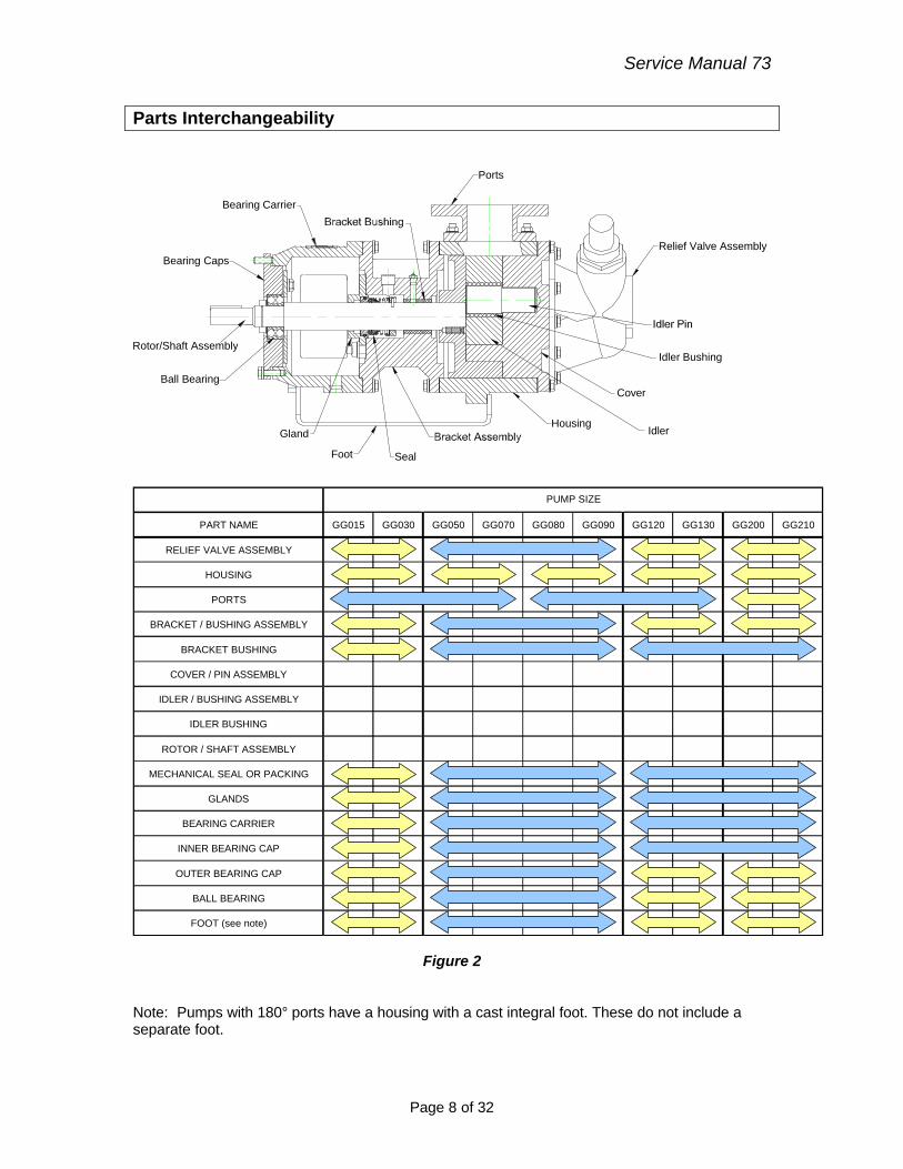
Parts Interchangeability
Idler Bushing
Cover
Idler
Rotor/Shaft Assembly
Ports
Bearing Carrier
Bearing Caps
Ball Bearing
Gland
Foot Seal
Relief Valve Assembly
Housing
PART NAME GG015 GG030 GG050 GG070 GG080 GG090 GG120 GG130 GG200 GG210
RELIEF VALVE ASSEMBLY
HOUSING
PORTS
BRACKET / BUSHING ASSEMBLY
BRACKET BUSHING
COVER / PIN ASSEMBLY
IDLER / BUSHING ASSEMBLY
IDLER BUSHING
ROTOR / SHAFT ASSEMBLY
MECHANICAL SEAL OR PACKING
GLANDS
BEARING CARRIER
INNER BEARING CAP
OUTER BEARING CAP
BALL BEARING
FOOT (see note)
PUMP SIZE
Figure 2
Note: Pumps with 180° ports have a housing with a cast integral foot. These do not include a separate foot.
Service Manual 73
Page 9 of 32
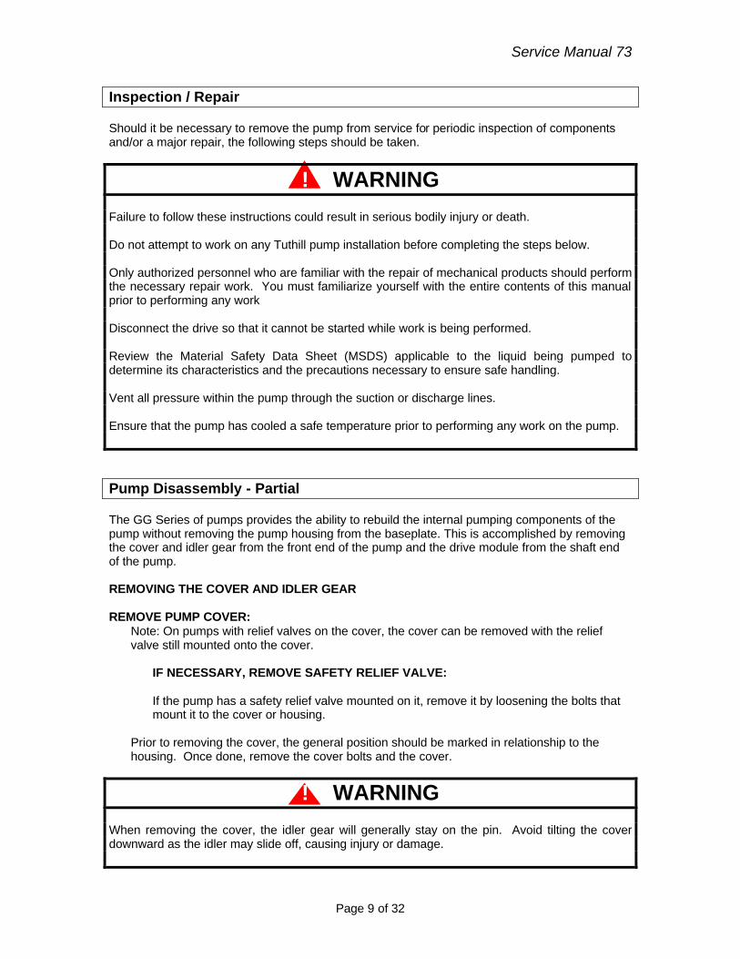
Inspection / Repair Should it be necessary to remove the pump from service for periodic inspection of components and/or a major repair, the following steps should be taken.
! WARNING
Failure to follow these instructions could result in serious bodily injury or death. Do not attempt to work on any Tuthill pump installation before completing the steps below. Only authorized personnel who are familiar with the repair of mechanical products should perform the necessary repair work. You must familiarize yourself with the entire contents of this manual prior to performing any work Disconnect the drive so that it cannot be started while work is being performed. Review the Material Safety Data Sheet (MSDS) applicable to the liquid being pumped to determine its characteristics and the precautions necessary to ensure safe handling. Vent all pressure within the pump through the suction or discharge lines. Ensure that the pump has cooled a safe temperature prior to performing any work on the pump. Pump Disassembly - Partial The GG Series of pumps provides the ability to rebuild the internal pumping components of the pump without removing the pump housing from the baseplate. This is accomplished by removing the cover and idler gear from the front end of the pump and the drive module from the shaft end of the pump. REMOVING THE COVER AND IDLER GEAR REMOVE PUMP COVER:
Note: On pumps with relief valves on the cover, the cover can be removed with the relief valve still mounted onto the cover.
IF NECESSARY, REMOVE SAFETY RELIEF VALVE:
If the pump has a safety relief valve mounted on it, remove it by loosening the bolts that mount it to the cover or housing.
Prior to removing the cover, the general position should be marked in relationship to the housing. Once done, remove the cover bolts and the cover.
! WARNING When removing the cover, the idler gear will generally stay on the pin. Avoid tilting the cover downward as the idler may slide off, causing injury or damage.
Service Manual 73
Page 10 of 32
REMOVE THE COVER GASKET: If a new gasket is not available, reuse of the original gasket is acceptable, provided it is not torn or otherwise damaged.
REMOVE THE IDLER FROM THE PIN:
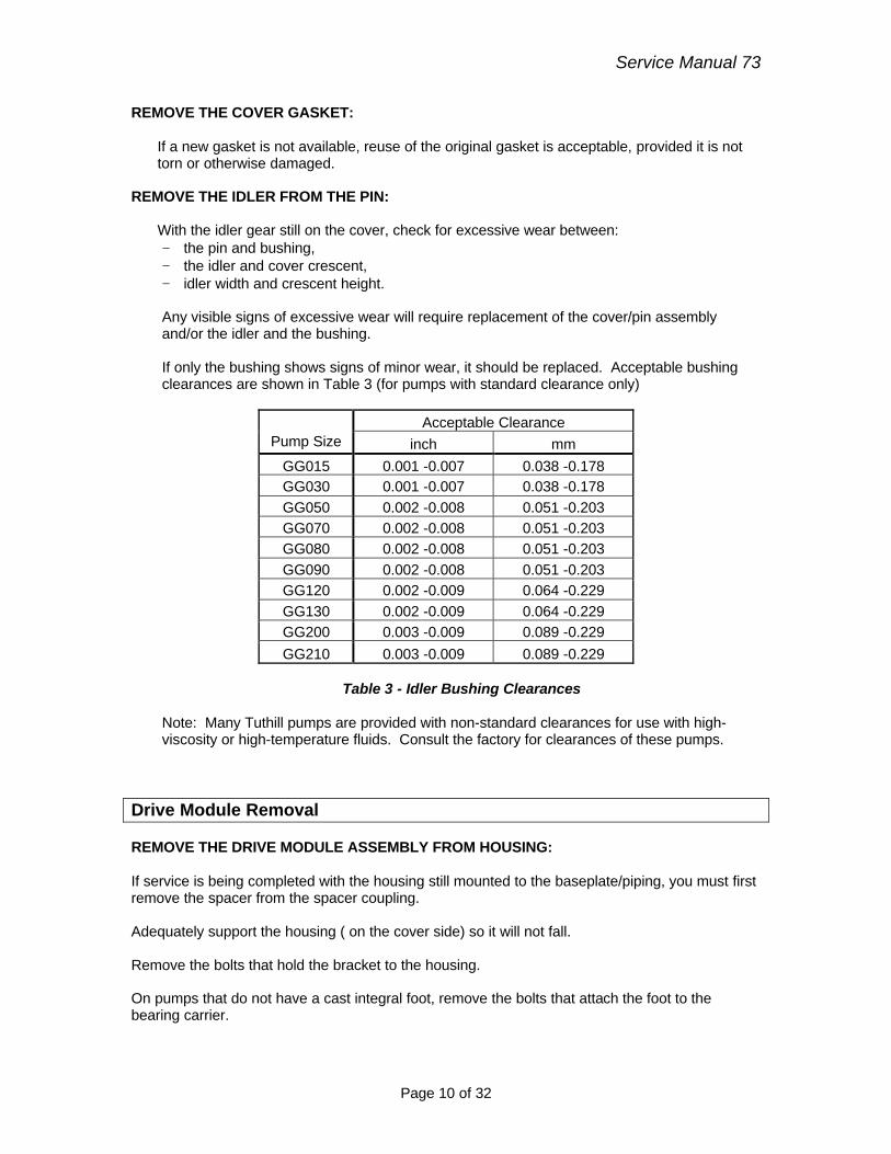
With the idler gear still on the cover, check for excessive wear between: − the pin and bushing, − the idler and cover crescent, − idler width and crescent height. Any visible signs of excessive wear will require replacement of the cover/pin assembly and/or the idler and the bushing. If only the bushing shows signs of minor wear, it should be replaced. Acceptable bushing clearances are shown in Table 3 (for pumps with standard clearance only)
Acceptable Clearance Pump Size inch mm
GG015 0.001 -0.007 0.038 -0.178 GG030 0.001 -0.007 0.038 -0.178 GG050 0.002 -0.008 0.051 -0.203 GG070 0.002 -0.008 0.051 -0.203 GG080 0.002 -0.008 0.051 -0.203 GG090 0.002 -0.008 0.051 -0.203 GG120 0.002 -0.009 0.064 -0.229 GG130 0.002 -0.009 0.064 -0.229 GG200 0.003 -0.009 0.089 -0.229 GG210 0.003 -0.009 0.089 -0.229
Table 3 - Idler Bushing Clearances
Note: Many Tuthill pumps are provided with non-standard clearances for use with high-viscosity or high-temperature fluids. Consult the factory for clearances of these pumps.
Drive Module Removal REMOVE THE DRIVE MODULE ASSEMBLY FROM HOUSING: If service is being completed with the housing still mounted to the baseplate/piping, you must first remove the spacer from the spacer coupling. Adequately support the housing ( on the cover side) so it will not fall. Remove the bolts that hold the bracket to the housing. On pumps that do not have a cast integral foot, remove the bolts that attach the foot to the bearing carrier.
Service Manual 73
Page 11 of 32
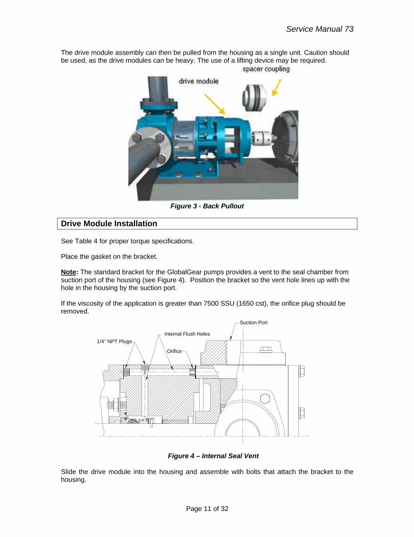
The drive module assembly can then be pulled from the housing as a single unit. Caution should be used, as the drive modules can be heavy. The use of a lifting device may be required.
Figure 3 - Back Pullout
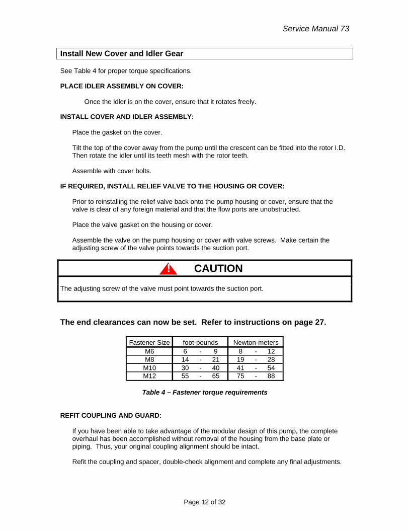
Drive Module Installation See Table 4 for proper torque specifications. Place the gasket on the bracket. Note: The standard bracket for the GlobalGear pumps provides a vent to the seal chamber from suction port of the housing (see Figure 4). Position the bracket so the vent hole lines up with the hole in the housing by the suction port. If the viscosity of the application is greater than 7500 SSU (1650 cst), the orifice plug should be removed.
Internal Flush Holes1/4" NPT Plugs
Suction Port
Orifice
Figure 4 – Internal Seal Vent
Slide the drive module into the housing and assemble with bolts that attach the bracket to the housing.
Service Manual 73
Page 12 of 32
Install New Cover and Idler Gear See Table 4 for proper torque specifications. PLACE IDLER ASSEMBLY ON COVER:
Once the idler is on the cover, ensure that it rotates freely.
INSTALL COVER AND IDLER ASSEMBLY:
Place the gasket on the cover. Tilt the top of the cover away from the pump until the crescent can be fitted into the rotor I.D. Then rotate the idler until its teeth mesh with the rotor teeth. Assemble with cover bolts.
IF REQUIRED, INSTALL RELIEF VALVE TO THE HOUSING OR COVER: Prior to reinstalling the relief valve back onto the pump housing or cover, ensure that the valve is clear of any foreign material and that the flow ports are unobstructed. Place the valve gasket on the housing or cover. Assemble the valve on the pump housing or cover with valve screws. Make certain the adjusting screw of the valve points towards the suction port.
! CAUTION The adjusting screw of the valve must point towards the suction port. The end clearances can now be set. Refer to instructions on page 27.
Fastener SizeM6 6 - 9 8 - 12M8 14 - 21 19 - 28
M10 30 - 40 41 - 54M12 55 - 65 75 - 88
foot-pounds Newton-meters
Table 4 – Fastener torque requirements REFIT COUPLING AND GUARD:
If you have been able to take advantage of the modular design of this pump, the complete overhaul has been accomplished without removal of the housing from the base plate or piping. Thus, your original coupling alignment should be intact. Refit the coupling and spacer, double-check alignment and complete any final adjustments.
Service Manual 73
Page 13 of 32
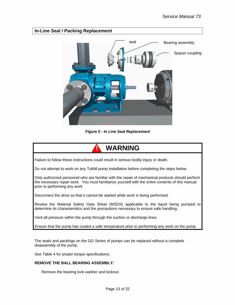
In-Line Seal / Packing Replacement
Figure 5 - In Line Seal Replacement
! WARNING
Failure to follow these instructions could result in serious bodily injury or death. Do not attempt to work on any Tuthill pump installation before completing the steps below. Only authorized personnel who are familiar with the repair of mechanical products should perform the necessary repair work. You must familiarize yourself with the entire contents of this manual prior to performing any work Disconnect the drive so that it cannot be started while work is being performed. Review the Material Safety Data Sheet (MSDS) applicable to the liquid being pumped to determine its characteristics and the precautions necessary to ensure safe handling. Vent all pressure within the pump through the suction or discharge lines. Ensure that the pump has cooled a safe temperature prior to performing any work on the pump. The seals and packings on the GG Series of pumps can be replaced without a complete disassembly of the pump. See Table 4 for proper torque specifications. REMOVE THE BALL BEARING ASSEMBLY:
Remove the bearing lock washer and locknut.
Spacer coupling
Bearing assembly seal
Service Manual 73
Page 14 of 32
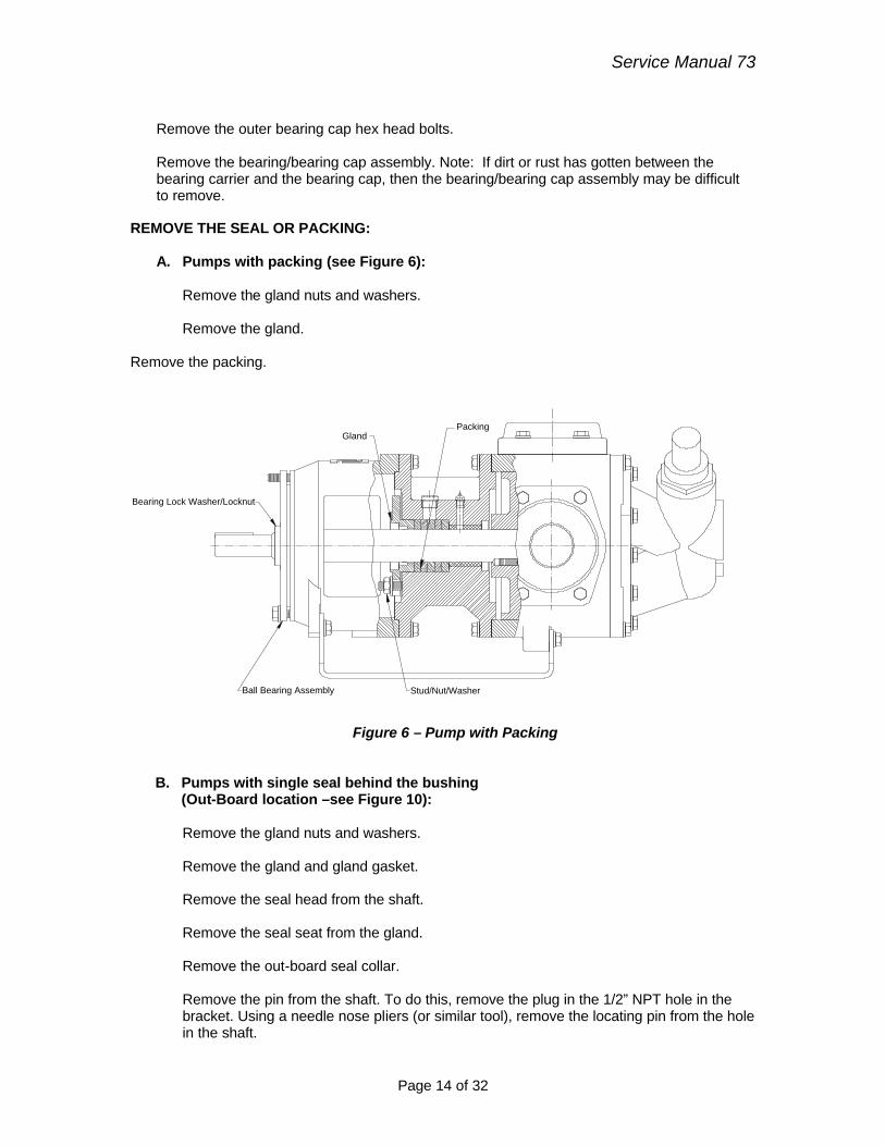
Remove the outer bearing cap hex head bolts. Remove the bearing/bearing cap assembly. Note: If dirt or rust has gotten between the bearing carrier and the bearing cap, then the bearing/bearing cap assembly may be difficult to remove.
REMOVE THE SEAL OR PACKING: A. Pumps with packing (see Figure 6):
Remove the gland nuts and washers. Remove the gland.
Remove the packing.
PackingGland
Stud/Nut/WasherBall Bearing Assembly
Bearing Lock Washer/Locknut
Figure 6 – Pump with Packing
B. Pumps with single seal behind the bushing (Out-Board location –see Figure 10):
Remove the gland nuts and washers. Remove the gland and gland gasket. Remove the seal head from the shaft. Remove the seal seat from the gland. Remove the out-board seal collar. Remove the pin from the shaft. To do this, remove the plug in the 1/2” NPT hole in the bracket. Using a needle nose pliers (or similar tool), remove the locating pin from the hole in the shaft.
Service Manual 73
Page 15 of 32
C. Pumps with cartridge seal
Consult the separate seal instructions provided by the seal manufacturer.
INSTALL PACKING OR SEAL:
A. Pumps with packing
Install and seat each ring into the bracket stuffing box and stagger cut joints from one side of the shaft to the other. Loosely install the gland, using the gland studs, nuts and washers. The packing will be adjusted on-site.
B. Pumps with single seal behind the bushing
(Out-Board location - See Figure 10)
It is always recommended to replace the rotor if scoring is present on the shaft. If the old one is being reused, lightly polish the shaft, in order to remove minor defects.
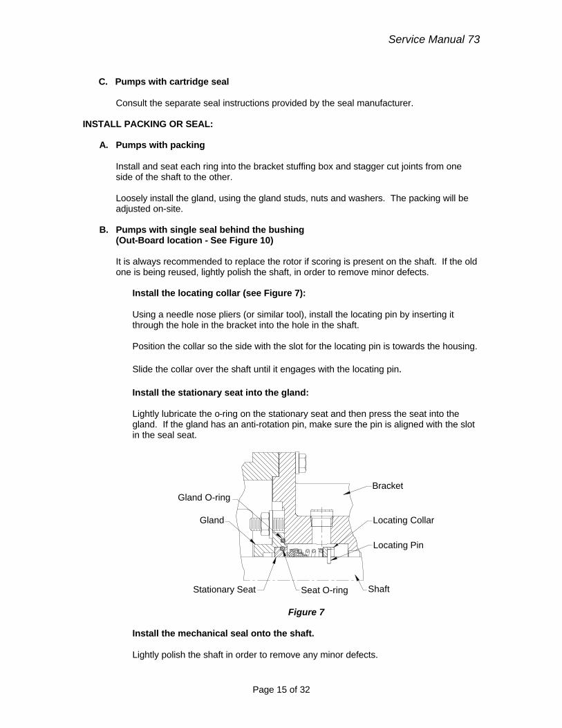
Install the locating collar (see Figure 7):
Using a needle nose pliers (or similar tool), install the locating pin by inserting it through the hole in the bracket into the hole in the shaft. Position the collar so the side with the slot for the locating pin is towards the housing. Slide the collar over the shaft until it engages with the locating pin.
Install the stationary seat into the gland:
Lightly lubricate the o-ring on the stationary seat and then press the seat into the gland. If the gland has an anti-rotation pin, make sure the pin is aligned with the slot in the seal seat.
Locating Pin
Locating Collar
Stationary Seat
Gland
BracketGland O-ring
Seat O-ring Shaft
Figure 7 Install the mechanical seal onto the shaft. Lightly polish the shaft in order to remove any minor defects.
Service Manual 73
Page 16 of 32
Place the seal head on the rotor shaft. A light lubricant will assist. Proper location of the seal is with the back portion against the collar. If the seal head has setscrews, tighten them once the seal head is properly located. Plug the access holes when finished with the ½ “ NPT plug.
! CAUTION The highly polished seal faces should not be touched during the assembly process as any minor scratch could result in leakage once in service.
Install the gland:
Slide the gland o-ring and gland over the shaft and position it onto the studs on the bracket. Install the washers and nuts and tighten.
C. Pumps with cartridge seal
Consult the separate seal instructions provided with the new seal.
INSTALL BALL BEARING ASSEMBLY
Place the inner bearing cap over the shaft. Install the new ball bearing onto the shaft. The bearing may have a slight press on the shaft so the bearing may have to be tapped on. Ensure that it bottoms out on the shaft shoulder. The bearing must be pressed on the inner race, not the outer race. Pressing on the outer race could damage the bearing.
! CAUTION Do not use excessive force when pressing the bearing onto the pump shaft, as it could damage the mechanical seal.
Install the bearing lock washer and locknut. After the locknut is tightened, bend one of the lock washer tabs into the locknut slot, to ensure that the locknut cannot vibrate loose. Loosely fit the inner and outer bearing caps to the bearing carrier, using the bearing cap screws. DO NOT tighten the bolts at this time.
The end clearances can now be set. Refer to instructions on page 27.
REFIT COUPLING AND GUARD: If you have been able to take advantage of the modular design of this pump, the complete overhaul has been accomplished without removal of the housing from the base plate or piping. Thus, your original coupling alignment should be intact. Refit the coupling and spacer, double-check alignment and complete any final adjustments.
Service Manual 73
Page 17 of 32
Pump-Complete Disassembly Procedure
! WARNING
Failure to follow these instructions could result in serious bodily injury or death. Do not attempt to work on any Tuthill pump installation before completing the steps below. Only authorized personnel who are familiar with the repair of mechanical products should perform the necessary repair work. You must familiarize yourself with the entire contents of this manual prior to performing any work Disconnect the drive so that it cannot be started while work is being performed. Review the Material Safety Data Sheet (MSDS) applicable to the liquid being pumped to determine its characteristics and the precautions necessary to ensure safe handling. Vent all pressure within the pump through the suction or discharge lines. Ensure that the pump has cooled a safe temperature prior to performing any work on the pump.
REMOVE THE PUMP FROM BASE:
The pump can be removed from the base for service or it can be disassembled without disturbing the housing, provided a spacer coupling was originally installed.
IF NECESSARY, REMOVE SAFETY RELIEF VALVE: If the pump has a safety relief valve mounted on it, remove it by loosening the bolts that mount it to the cover or housing.
REMOVE PUMP COVER:
Note: On pumps with relief valves on the cover, the cover can be removed with the relief valve still mounted onto the cover. Prior to removing the cover, the general position should be marked in relationship to the housing. Once done, remove the cover bolts and the cover.
! CAUTION When removing the cover, the idler gear will generally stay on the pin. Avoid tilting the cover downward as the idler may slide off, causing injury or damage.
REMOVE THE COVER GASKET:
If a new gasket is not available, reuse of the original gasket is acceptable, provided it is not torn or otherwise damaged.
Service Manual 73
Page 18 of 32
REMOVE THE IDLER FROM THE PIN:
With the idler gear still on the cover, check for excessive wear between: − the pin and bushing, − the idler and cover crescent, − idler width and crescent height. Any visible signs of excessive wear will require replacement of the cover/pin assembly and/or the idler and the bushing. If only the bushing shows signs of minor wear, it should be replaced. Acceptable bushing clearances are shown in the Table 3 (for pumps with standard clearance only).
Note: Many Tuthill pumps are provided with non-standard clearances for use with high-viscosity or high-temperature fluids. Consult the factory for clearances of these pumps.
REMOVE THE DRIVE MODULE ASSEMBLY FROM HOUSING:
If service is being completed with the housing still mounted to the baseplate/piping, you must first remove the spacer from the spacer coupling. Adequately support the housing ( on the cover side) so it will not fall. Remove the bolts that hold the bracket to the housing. On pumps that do not have a cast integral foot, remove the bolts that attach the foot to the bearing carrier. The drive module assembly can then be pulled from the housing as a single unit. Caution should be used, as the drive modules can be heavy. The use of a lifting device may be required.
REMOVE THE BALL BEARING ASSEMBLY: Remove the bearing lock washer and locknut. Remove the outer bearing cap hex head bolts. Remove the bearing/bearing caps assembly. Note: If dirt or rust has gotten between the bearing carrier and the bearing cap, then the bearing/bearing cap assembly may be difficult to remove. Remove the three bolts that hold the inner bearing cap in place and remove the inner bearing cap. Remove the outer bearing cap. Remove the bearing from the shaft. There may be a slight press-fit between the shaft and bearing. Use a bearing puller or other appropriate tool if required.
REMOVE THE SEAL OR PACKING: A. Pumps with packing:
Remove the gland nuts and washers.
Service Manual 73
Page 19 of 32
Remove the gland. Remove the packing. The rotor and bracket can now be separated.
B. Pumps with single seal behind the rotor (In-Board location-see Figure 9):
Remove the bracket. Remove the seal head from the shaft, directly behind the rotor head. Remove the in-board seal gland from inside the bracket. Remove the seal seat from the in-board seal gland.
C. Pumps with single seal behind the bushing
(Out-Board location-see Figure 10):
Remove the gland nuts and washers. Remove the gland and gland gasket. Remove the seal head from the shaft. Remove the seal seat from the gland. Remove the out-board seal collar. Remove the pin from the shaft. To do this, remove the plug in the ½” NPT hole in the bracket. Using a needle nose pliers (or similar tool), remove the locating pin from the hole in the shaft. The rotor and bracket can now be separated.
D. Pumps with cartridge seal:
Consult the separate seal instructions provided bt the seal manufacturer.
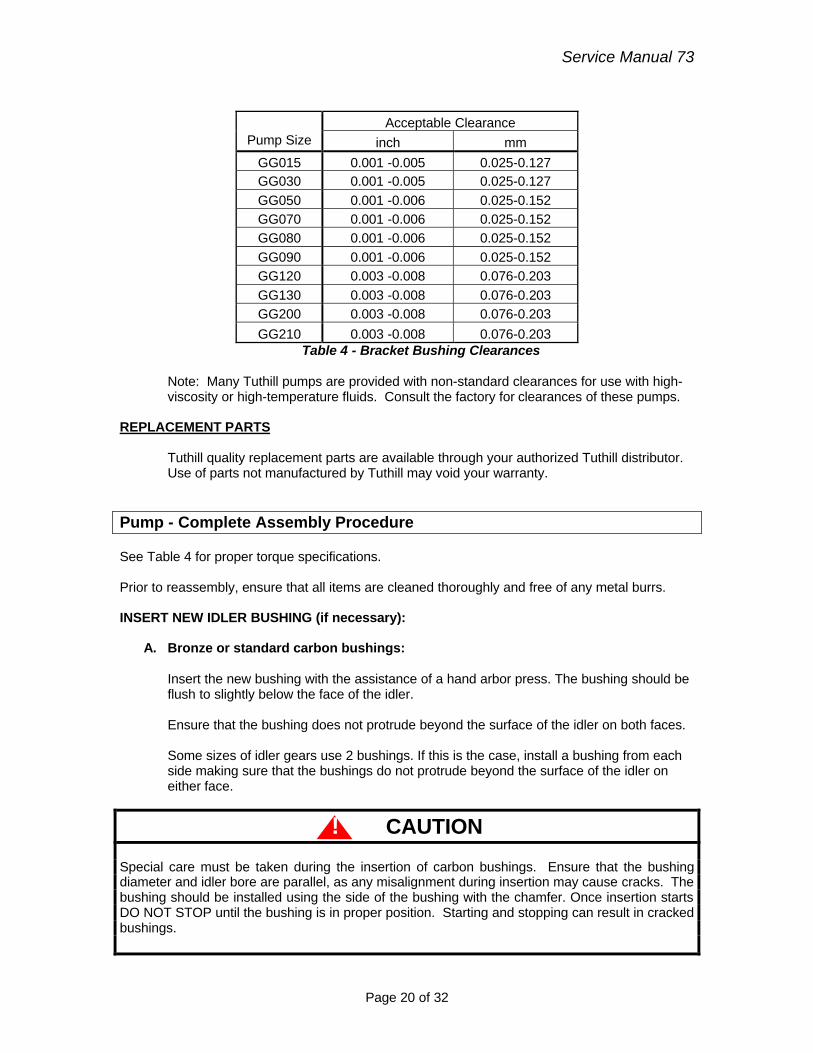
CLEAN AND INSPECT: Clean all parts and inspect for signs of excessive wear or scoring and replace if necessary. Any signs of excessive wear between the bracket bushing and shaft may also cause housing wear. This should be checked. If only the bracket bushing shows signs of minor wear it should be replaced. Acceptable bushing clearances are shown in Table 4 (for pumps with standard clearance only)
Service Manual 73
Page 20 of 32
Acceptable Clearance
Pump Size inch mm GG015 0.001 -0.005 0.025-0.127 GG030 0.001 -0.005 0.025-0.127 GG050 0.001 -0.006 0.025-0.152 GG070 0.001 -0.006 0.025-0.152 GG080 0.001 -0.006 0.025-0.152 GG090 0.001 -0.006 0.025-0.152 GG120 0.003 -0.008 0.076-0.203 GG130 0.003 -0.008 0.076-0.203 GG200 0.003 -0.008 0.076-0.203 GG210 0.003 -0.008 0.076-0.203
Table 4 - Bracket Bushing Clearances
Note: Many Tuthill pumps are provided with non-standard clearances for use with high-viscosity or high-temperature fluids. Consult the factory for clearances of these pumps.
REPLACEMENT PARTS
Tuthill quality replacement parts are available through your authorized Tuthill distributor. Use of parts not manufactured by Tuthill may void your warranty.
Pump - Complete Assembly Procedure See Table 4 for proper torque specifications. Prior to reassembly, ensure that all items are cleaned thoroughly and free of any metal burrs. INSERT NEW IDLER BUSHING (if necessary):
A. Bronze or standard carbon bushings:
Insert the new bushing with the assistance of a hand arbor press. The bushing should be flush to slightly below the face of the idler. Ensure that the bushing does not protrude beyond the surface of the idler on both faces. Some sizes of idler gears use 2 bushings. If this is the case, install a bushing from each side making sure that the bushings do not protrude beyond the surface of the idler on either face.
! CAUTION Special care must be taken during the insertion of carbon bushings. Ensure that the bushing diameter and idler bore are parallel, as any misalignment during insertion may cause cracks. The bushing should be installed using the side of the bushing with the chamfer. Once insertion starts DO NOT STOP until the bushing is in proper position. Starting and stopping can result in cracked bushings.
Service Manual 73
Page 21 of 32
On idlers that use bronze bushings, there is a hole through the root diameter of one of the teeth. Use this hole to drill a hole through the bronze bushing.
B. Tungsten carbide or high-temperature carbon bushings:
Heat the idler gear evenly to about 400°F (204°C). Set the heated idler gear on a flat surface. Drop the bushing into the idler gear; making certain that the bushing is flush to slightly below the face of the idler. Ensure that the bushing does not protrude beyond the surface of the idler on both faces. Some sizes of idler gears use two bushings. If this is the case, install a bushing from each side making sure that the bushings do not protrude beyond the surface of the idler on either face. Allow the idler to air-cool to room temperature.
! WARNING
Wear heat-resistant gloves when handling hot components.
INSERT NEW BRACKET BUSHING (if necessary):
A. Bronze or standard carbon bushings:
Insert the new bushing with the assistance of a hand arbor press. Always install the bushing from the chamfered end of the bracket.
! CAUTION Special care must be taken during the insertion of carbon bushings. Ensure that the bushing diameter and idler bore are parallel, as any misalignment during insertion may cause cracks. The bushing should be installed using the side of the bushing with the chamfer. Once insertion starts DO NOT STOP until the bushing is in proper position. Starting and stopping can result in cracked bushings.
On brackets that use bronze bushings, there is a hole through the bracket above the bushing. Use this hole to drill a hole through the bronze bushing.
B. Tungsten carbide or high-temperature carbon bushings:
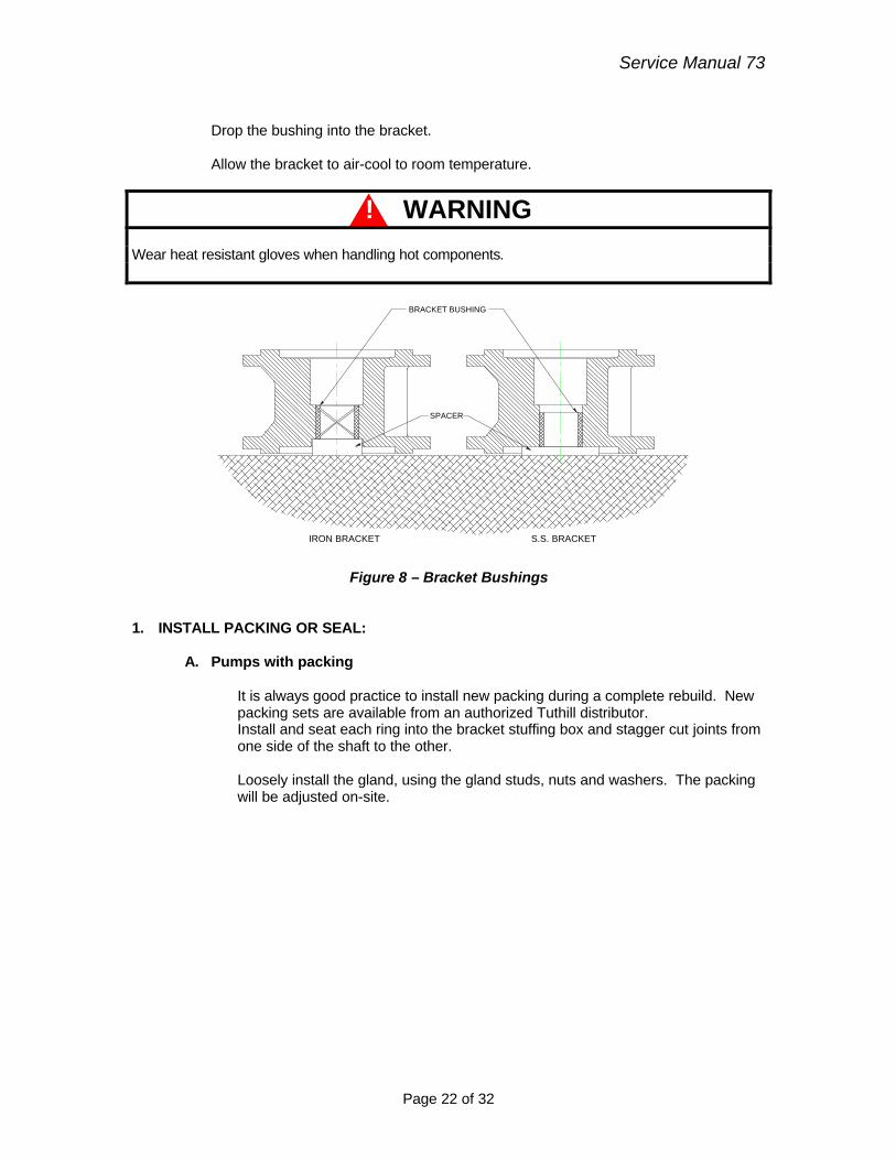
Heat the bracket evenly to about 400°F (204°C). Set the heated bracket on a flat surface. Use a spacer block to properly locate the bushing (see Figure 8).
Service Manual 73
Page 22 of 32
Drop the bushing into the bracket. Allow the bracket to air-cool to room temperature.
! WARNING
Wear heat resistant gloves when handling hot components.
SPACER
BRACKET BUSHING
IRON BRACKET S.S. BRACKET
Figure 8 – Bracket Bushings
1. INSTALL PACKING OR SEAL:
A. Pumps with packing
It is always good practice to install new packing during a complete rebuild. New packing sets are available from an authorized Tuthill distributor. Install and seat each ring into the bracket stuffing box and stagger cut joints from one side of the shaft to the other.
Loosely install the gland, using the gland studs, nuts and washers. The packing will be adjusted on-site.
Service Manual 73
Page 23 of 32
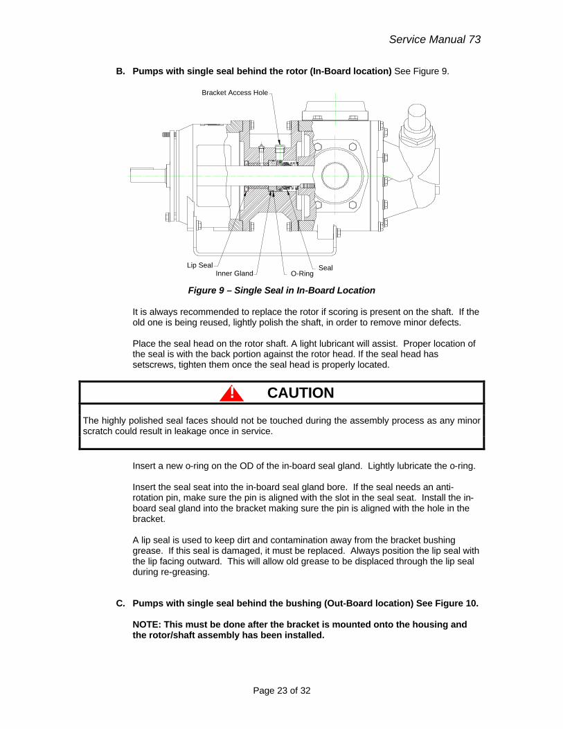
B. Pumps with single seal behind the rotor (In-Board location) See Figure 9.
O-RingSeal
Bracket Access Hole
Inner Gland Lip Seal
Figure 9 – Single Seal in In-Board Location
It is always recommended to replace the rotor if scoring is present on the shaft. If the old one is being reused, lightly polish the shaft, in order to remove minor defects. Place the seal head on the rotor shaft. A light lubricant will assist. Proper location of the seal is with the back portion against the rotor head. If the seal head has setscrews, tighten them once the seal head is properly located.
! CAUTION The highly polished seal faces should not be touched during the assembly process as any minor scratch could result in leakage once in service.
Insert a new o-ring on the OD of the in-board seal gland. Lightly lubricate the o-ring. Insert the seal seat into the in-board seal gland bore. If the seal needs an anti-rotation pin, make sure the pin is aligned with the slot in the seal seat. Install the in-board seal gland into the bracket making sure the pin is aligned with the hole in the bracket. A lip seal is used to keep dirt and contamination away from the bracket bushing grease. If this seal is damaged, it must be replaced. Always position the lip seal with the lip facing outward. This will allow old grease to be displaced through the lip seal during re-greasing.
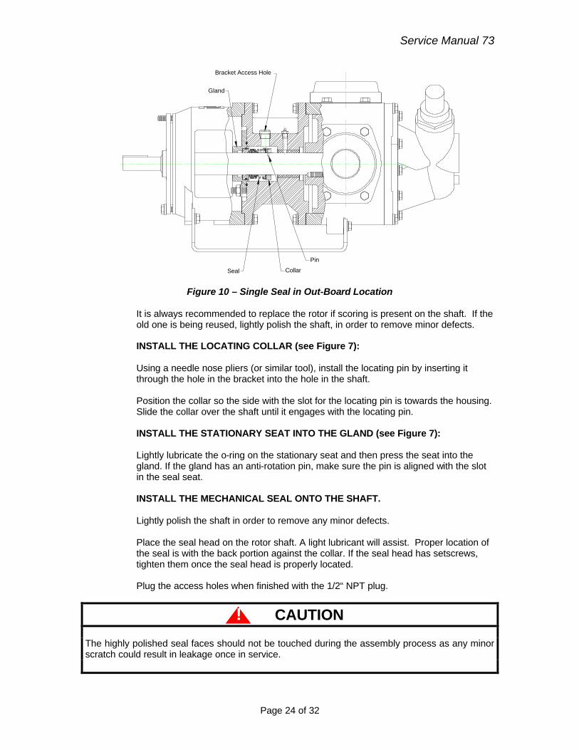
C. Pumps with single seal behind the bushing (Out-Board location) See Figure 10. NOTE: This must be done after the bracket is mounted onto the housing and the rotor/shaft assembly has been installed.
Service Manual 73
Page 24 of 32
Bracket Access Hole
Seal
Gland
Collar
Pin
Figure 10 – Single Seal in Out-Board Location
It is always recommended to replace the rotor if scoring is present on the shaft. If the old one is being reused, lightly polish the shaft, in order to remove minor defects.
INSTALL THE LOCATING COLLAR (see Figure 7): Using a needle nose pliers (or similar tool), install the locating pin by inserting it through the hole in the bracket into the hole in the shaft. Position the collar so the side with the slot for the locating pin is towards the housing. Slide the collar over the shaft until it engages with the locating pin. INSTALL THE STATIONARY SEAT INTO THE GLAND (see Figure 7): Lightly lubricate the o-ring on the stationary seat and then press the seat into the gland. If the gland has an anti-rotation pin, make sure the pin is aligned with the slot in the seal seat. INSTALL THE MECHANICAL SEAL ONTO THE SHAFT. Lightly polish the shaft in order to remove any minor defects. Place the seal head on the rotor shaft. A light lubricant will assist. Proper location of the seal is with the back portion against the collar. If the seal head has setscrews, tighten them once the seal head is properly located. Plug the access holes when finished with the 1/2“ NPT plug.
! CAUTION The highly polished seal faces should not be touched during the assembly process as any minor scratch could result in leakage once in service.
Service Manual 73
Page 25 of 32
INSTALL THE GLAND Slide the gland o-ring and gland over the shaft and position it onto the studs on the bracket. Install the washers and nuts and tighten. FLUSH ARRANGEMENTS (see Figure 4) Note: The standard bracket for the GlobalGear pumps provides a vent to the seal chamber from suction port of the housing (see Figure 4). Position the bracket so the vent hole lines up with the hole in the housing by the suction port. If the viscosity of the application is greater than 7500 SSU (1650 cst), the orifice plug should be removed.
D. Pumps with cartridge seal Consult the separate seal instructions provided with the new seal.
Rebuild Drive Module Assembly See Table 4 for proper torque specifications. Place the rotor into the bracket and place this assembly on a flat surface so the shaft points upward. Note: The standard bracket for the GlobalGear pumps provides a vent to the seal chamber from suction port of the housing (see Figure 4). Position the bracket so the vent hole lines up with the hole in the housing by the suction port. If the viscosity of the application is greater than 7500 SSU (1650 cst), the orifice plug should be removed. Install the bearing carrier onto the bracket. Place the inner bearing cap over the shaft. Install the new ball bearing onto the shaft. The bearing may have a slight press on the shaft so the bearing may have to be tapped on. Ensure that it bottoms out on the shaft shoulder. The bearing must be pressed on the inner race, not the outer race. Pressing on the outer race could damage the bearing.
! CAUTION Do not use excessive force when pressing the bearing onto the pump shaft, as it could damage the mechanical seal. Install the bearing lock washer and locknut. After the locknut is tightened, bend one of the lock washer tabs into the locknut slot, to ensure that the locknut cannot vibrate loose.
Service Manual 73
Page 26 of 32
Loosely fit the inner and outer bearing caps to the bearing carrier, using the bearing cap screws. DO NOT tighten the screws at this time. INSTALL DRIVE MODULE TO HOUSING:
Place the gasket on the bracket. Slide the drive module into the housing and assemble with drive module bolts. Verify that the flush holes in the bracket are lined up with the appropriate hole in the housing.
PLACE IDLER ASSEMBLY ON COVER: Once the idler is on the cover, ensure that it rotates freely.
INSTALL COVER AND IDLER ASSEMBLY: Place the gasket on the cover. Tilt the top of the cover away from the pump until the crescent can be fitted into the rotor I.D. Then rotate the idler until its teeth mesh with the rotor teeth. Assemble with cover bolts.
INSTALL RELIEF VALVE TO THE HOUSING OR COVER:
Prior to reinstalling the relief valve back onto the pump housing or cover, ensure that the valve is clear of any foreign material and that the flow ports are unobstructed. Place the valve gasket on the housing or cover. Assemble the valve on the pump housing or cover with valve screws. Make certain the adjusting screw of the valve points towards the suction port.
! CAUTION The adjusting screw of the valve must point towards the suction port.
Service Manual 73
Page 27 of 32
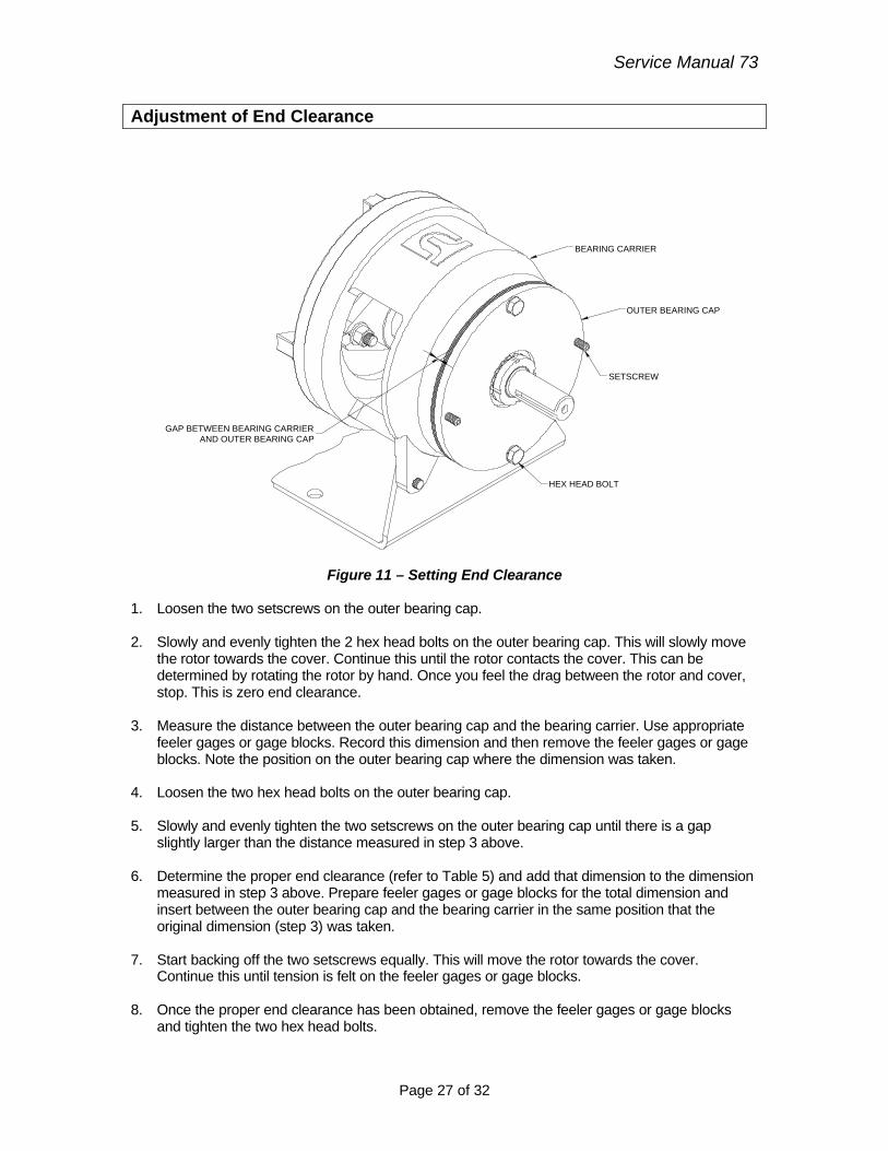
Adjustment of End Clearance
GAP BETWEEN BEARING CARRIERAND OUTER BEARING CAP
HEX HEAD BOLT
OUTER BEARING CAP
BEARING CARRIER
SETSCREW
Figure 11 – Setting End Clearance
1. Loosen the two setscrews on the outer bearing cap. 2. Slowly and evenly tighten the 2 hex head bolts on the outer bearing cap. This will slowly move
the rotor towards the cover. Continue this until the rotor contacts the cover. This can be determined by rotating the rotor by hand. Once you feel the drag between the rotor and cover, stop. This is zero end clearance.
3. Measure the distance between the outer bearing cap and the bearing carrier. Use appropriate
feeler gages or gage blocks. Record this dimension and then remove the feeler gages or gage blocks. Note the position on the outer bearing cap where the dimension was taken.
4. Loosen the two hex head bolts on the outer bearing cap. 5. Slowly and evenly tighten the two setscrews on the outer bearing cap until there is a gap
slightly larger than the distance measured in step 3 above. 6. Determine the proper end clearance (refer to Table 5) and add that dimension to the dimension
measured in step 3 above. Prepare feeler gages or gage blocks for the total dimension and insert between the outer bearing cap and the bearing carrier in the same position that the original dimension (step 3) was taken.
7. Start backing off the two setscrews equally. This will move the rotor towards the cover.
Continue this until tension is felt on the feeler gages or gage blocks. 8. Once the proper end clearance has been obtained, remove the feeler gages or gage blocks
and tighten the two hex head bolts.
Service Manual 73
Page 28 of 32
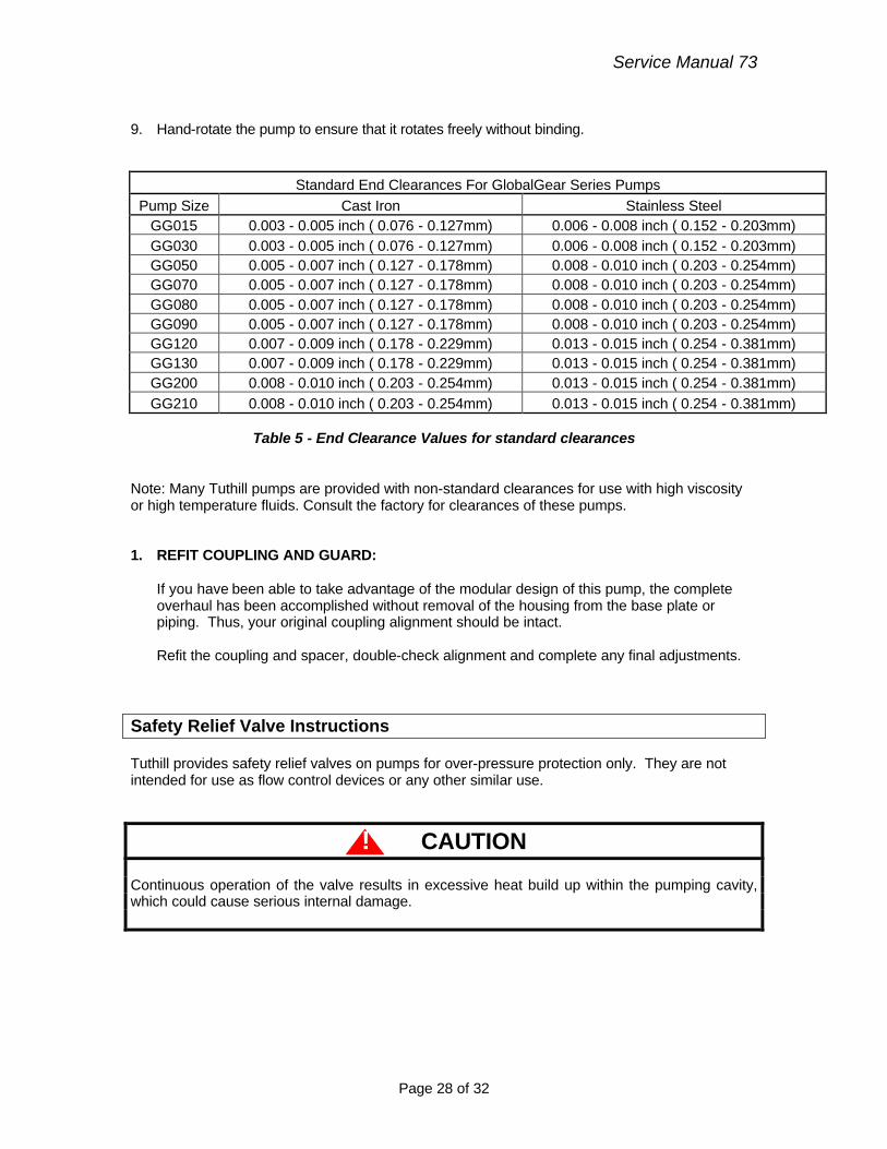
9. Hand-rotate the pump to ensure that it rotates freely without binding.
Standard End Clearances For GlobalGear Series Pumps Pump Size Cast Iron Stainless Steel
GG015 0.003 - 0.005 inch ( 0.076 - 0.127mm) 0.006 - 0.008 inch ( 0.152 - 0.203mm) GG030 0.003 - 0.005 inch ( 0.076 - 0.127mm) 0.006 - 0.008 inch ( 0.152 - 0.203mm) GG050 0.005 - 0.007 inch ( 0.127 - 0.178mm) 0.008 - 0.010 inch ( 0.203 - 0.254mm) GG070 0.005 - 0.007 inch ( 0.127 - 0.178mm) 0.008 - 0.010 inch ( 0.203 - 0.254mm) GG080 0.005 - 0.007 inch ( 0.127 - 0.178mm) 0.008 - 0.010 inch ( 0.203 - 0.254mm) GG090 0.005 - 0.007 inch ( 0.127 - 0.178mm) 0.008 - 0.010 inch ( 0.203 - 0.254mm) GG120 0.007 - 0.009 inch ( 0.178 - 0.229mm) 0.013 - 0.015 inch ( 0.254 - 0.381mm) GG130 0.007 - 0.009 inch ( 0.178 - 0.229mm) 0.013 - 0.015 inch ( 0.254 - 0.381mm) GG200 0.008 - 0.010 inch ( 0.203 - 0.254mm) 0.013 - 0.015 inch ( 0.254 - 0.381mm) GG210 0.008 - 0.010 inch ( 0.203 - 0.254mm) 0.013 - 0.015 inch ( 0.254 - 0.381mm)
Table 5 - End Clearance Values for standard clearances
Note: Many Tuthill pumps are provided with non-standard clearances for use with high viscosity or high temperature fluids. Consult the factory for clearances of these pumps. 1. REFIT COUPLING AND GUARD:
If you have been able to take advantage of the modular design of this pump, the complete overhaul has been accomplished without removal of the housing from the base plate or piping. Thus, your original coupling alignment should be intact. Refit the coupling and spacer, double-check alignment and complete any final adjustments.
Safety Relief Valve Instructions Tuthill provides safety relief valves on pumps for over-pressure protection only. They are not intended for use as flow control devices or any other similar use.
! CAUTION Continuous operation of the valve results in excessive heat build up within the pumping cavity, which could cause serious internal damage.
Service Manual 73
Page 29 of 32
BODY
JAM NUT
BONNET GASKET
ADJUSTING SCREW
CAP GASKET
CAP
SPRING
BONNET
SPRING GUIDE
POPPET
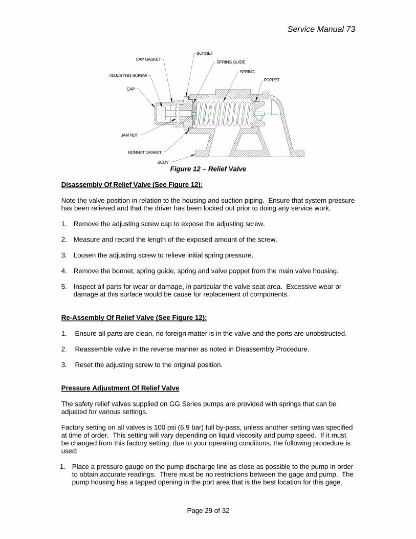
Figure 12 – Relief Valve
Disassembly Of Relief Valve (See Figure 12): Note the valve position in relation to the housing and suction piping. Ensure that system pressure has been relieved and that the driver has been locked out prior to doing any service work. 1. Remove the adjusting screw cap to expose the adjusting screw. 2. Measure and record the length of the exposed amount of the screw. 3. Loosen the adjusting screw to relieve initial spring pressure. 4. Remove the bonnet, spring guide, spring and valve poppet from the main valve housing. 5. Inspect all parts for wear or damage, in particular the valve seat area. Excessive wear or
damage at this surface would be cause for replacement of components. Re-Assembly Of Relief Valve (See Figure 12): 1. Ensure all parts are clean, no foreign matter is in the valve and the ports are unobstructed. 2. Reassemble valve in the reverse manner as noted in Disassembly Procedure. 3. Reset the adjusting screw to the original position. Pressure Adjustment Of Relief Valve The safety relief valves supplied on GG Series pumps are provided with springs that can be adjusted for various settings. Factory setting on all valves is 100 psi (6.9 bar) full by-pass, unless another setting was specified at time of order. This setting will vary depending on liquid viscosity and pump speed. If it must be changed from this factory setting, due to your operating conditions, the following procedure is used: 1. Place a pressure gauge on the pump discharge line as close as possible to the pump in order
to obtain accurate readings. There must be no restrictions between the gage and pump. The pump housing has a tapped opening in the port area that is the best location for this gage.
Service Manual 73
Page 30 of 32
2. Remove the adjusting screw cap and gasket to expose the adjusting screw. 3. Loosen the lock nut. 4. Start the pump running. 5. Slowly restrict the discharge line, while observing the pressure gage. Stop immediately if the
pressure rises above a safe level. 6. With the discharge line fully closed, the gauge will read the full by-pass pressure setting for
the current speed and viscosity. Do not leave the discharge line closed for a long time, since the fluid temperature will rise rapidly.
7. Adjust the valve adjusting screw to obtain the desired full by-pass setting. Tighten the screw
to increase the setting, and loosen it to reduce the setting. 8. Once set, reopen the discharge line. 9. This setting should be 15 to 25 percent above normal operating pressure presented by the
system to ensure the valve does not operate during normal use.
! CAUTION If there is some other flow control device present in the system that will vary the system pressure, the relief valve setting should be set above this pressure to ensure the valve does not function during normal use. 10. Tighten the lock nut. 11. Install the adjusting screw cap and gasket. Troubleshooting 1. Problem: No fluid is delivered.
a. Power is not on.
b. Net positive suction head available (NPSHa) is lower than required for the vapor pressure of the liquid pumped. You should calculate NPSHa and redesign piping, if necessary.
c. Leaks in suction line or port passages. These can be detected by submerging pressure line from discharge side of pump into a pail of liquid where the air will be seen in the form of bubbles.
d. Direction of shaft rotation is incorrect.
e. Relief valve setting is too low. Liquid is discharging through the by-pass port.

Service Manual 73
Page 31 of 32
2. Problem: Capacity is too low.
a. Air leaks in suction line. b. Suction losses are too high. The suction lift is too great or the suction line is too small or
too long. This can be detected by installing a vacuum gauge directly at the pump suction. The maximum vacuum at the pump suction should never exceed 15” of mercury. Vaporization caused by higher vacuums will generally result in capacity drop off. Redesign suction conditions.
c. Pump speed is too slow. d. Strainer too small or obstructed. e. Suction pipe or port not immersed in liquid deep enough f. Piping improperly installed permitting air pocket to form in the pump. g. Increased clearances or wear in the pump will sometimes cause the pump to deliver an
insufficient supply of liquid. This may be corrected by reducing the thickness of the cover gaskets. A folded gasket or a slight amount of dirt can exaggerate the problem and cause leakage. Refer to Assembly Procedure section for minimum end clearances.
3. Problem: Pump works spasmodically. a. Leaky suction lines.
b. Suction conditions vary.
c. Air or vapor in liquid.
4. Problem: Excessive power draw.
a. Pressure too high. b. Liquid more viscous than originally expected. c. Suction or discharge lines obstructed. d. Insufficient horsepower. e. Mechanical defects:
i. Drive shaft and pump are misaligned. ii. Pump is binding due to insufficient end clearance. iii. Pump shaft is bent. iv. Misalignment within pump due to bad piping or poor installation, causing strain or
distortion.
Service Manual 73
Page 32 of 32
5. Problem: Pump is noisy.
a. Pump is cavitating due to inadequate suction conditions. b. Misalignment of coupling. c. Coupling set too close to pump. d. Vibration of pump due to worn or bent shaft. e. Air leaks on suction side of pump or air entrainment in fluid.
6. Problem: Pump leaks. a. Bolts need tightening, allowing gaskets or o-rings to leak. b. Gaskets or o-rings are damaged.
Note: Packings are designed to leak. Leakage should be at a rate that will prevent excessive heating on the bracket at the packing area. Material Returns If it becomes necessary to return a pump to the factory, a Return Goods Authorization (RGA) must be obtained from either your local Authorized Distributor or our Alsip plant. No RGA can be issued until a completed Material Safety Data Sheet (MSDS) has been forwarded to our Alsip plant and return of the pump approved.
• Tuthill pumps are precision built and must be handled with care. • Pumps must be drained of all fluid and the ports plugged to prevent foreign material
from getting into the pump. • Pumps must be packaged securely to prevent damage while in transit.
12/01/2001