Embed Size (px)
Citation preview
Baxi Combi 80Eco Gas Fired Wall Mounted Combination Boiler
Installation and Servicing Instructions
Please leave these instructions with the user
2
Baxi UK Limited is one of the leading manufacturers
of domestic heating products in the UK.
Our first priority is to give a high quality service to our
customers. Quality is designed into every Baxi product
- products which fulfil the demands and needs of
customers, offering choice, efficiency and reliability.
To keep ahead of changing trends, we have made a
commitment to develop new ideas using the
latest technology - with the aim of continuing to make
the products that customers want to buy.
Everyone who works at Baxi has a commitment to
quality because we know that satisfied customers
mean continued success.
We hope you get a satisfactory service from Baxi. If
not, please let us know.
Natural Gas
Baxi Combi 80EcoG.C.No 47 075 05
Baxi is a BS-EN ISO 9001 Accredited Company
The boiler meets the requirements of Statutory Instrument“ The Boiler (Efficiency) Regulations 1993 No 3083” and isdeemed to meet the requirements of Directive 92/42/EECon the energy efficiency requirements for new hot waterboilers fired with liquid or gaseous fuels:-
Type test for purpose of Regulation 5 certified by: Notified Body 0051.
Product/Production certified by:Notified Body 0051.
For GB/IE only.
3
1.0 Introduction 4
2.0 General Layout 5
3.0 Appliance Operation 6
4.0 Technical Data 7
5.0 Dimensions and Fixings 8
6.0 System Details 9
7.0 Site Requirements 12
8.0 Installation 17
9.0 Commissioning the Boiler 22
10.0 Completion 24
11.0 Servicing the Boiler 25
12.0 Changing Components 27
13.0 Illustrated Wiring Diagram 36
14.0 Fault Finding 37
15.0 Short Parts List 42
Section Page
Contents
Baxi UK Limited declare that no substancesharmful to health are contained in theappliance or used during appliancemanufacture.
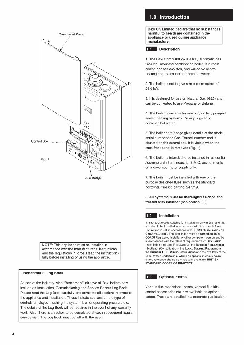
1.1 Description
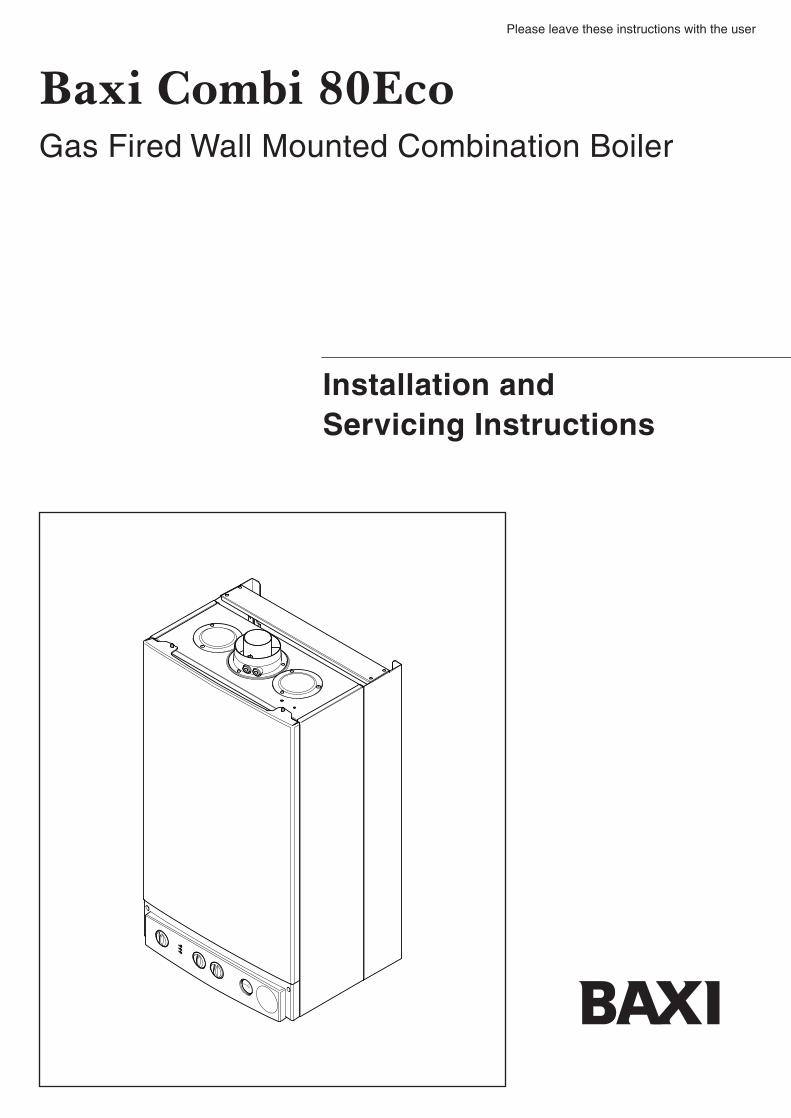
1. The Baxi Combi 80Eco is a fully automatic gasfired wall mounted combination boiler. It is roomsealed and fan assisted, and will serve centralheating and mains fed domestic hot water.
2. The boiler is set to give a maximum output of 24.0 kW.
3. It is designed for use on Natural Gas (G20) andcan be converted to use Propane or Butane.
4. The boiler is suitable for use only on fully pumpedsealed heating systems. Priority is given todomestic hot water.
5. The boiler data badge gives details of the model,serial number and Gas Council number and issituated on the control box. It is visible when thecase front panel is removed (Fig. 1).
6. The boiler is intended to be installed in residential/ commercial / light industrial E.M.C. environmentson a governed meter supply only.
7. The boiler must be installed with one of thepurpose designed flues such as the standardhorizontal flue kit, part no. 247719.
8. All systems must be thoroughly flushed andtreated with inhibitor (see section 6.2).
1.2 Installation
1. The appliance is suitable for installation only in G.B. and I.E.and should be installed in accordance with the rules in force.For Ireland install in accordance with I.S.813 “INSTALLATION OF
GAS APPLIANCES”. The installation must be carried out by aCORGI Registered Installer or other competent person and bein accordance with the relevant requirements of GAS SAFETY
(Installation and Use) REGULATIONS, the BUILDING REGULATIONS
(Scotland) (Consolidation), the LOCAL BUILDING REGULATIONS,the CURRENT I.E.E. WIRING REGULATIONS and the bye laws of theLocal Water Undertaking. Where no specific instructions aregiven, reference should be made to the relevant BRITISHSTANDARD CODES OF PRACTICE.
1.3 Optional Extras
Various flue extensions, bends, vertical flue kits,control accessories etc. are available as optionalextras. These are detailed in a separate publication.
1.0 Introduction
4
Data Badge
Fig. 1
Control Box
Case Front Panel
“Benchmark” Log Book
As part of the industry-wide “Benchmark” initiative all Baxi boilers nowinclude an Installation, Commissioning and Service Record Log Book.Please read the Log Book carefully and complete all sections relevant tothe appliance and installation. These include sections on the type ofcontrols employed, flushing the system, burner operating pressure etc.The details of the Log Book will be required in the event of any warrantywork. Also, there is a section to be completed at each subsequent regularservice visit. The Log Book must be left with the user.
NOTE: This appliance must be installed inaccordance with the manufacturer’s instructionsand the regulations in force. Read the instructionsfully before installing or using the appliance.
2.0 General Layout
5
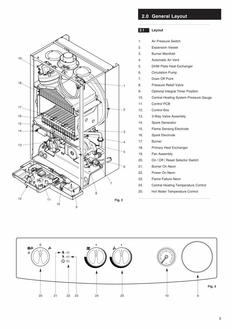
2.1 Layout
1. Air Pressure Switch
2. Expansion Vessel
3. Burner Manifold
4. Automatic Air Vent
5. DHW Plate Heat Exchanger
6. Circulation Pump
7. Drain Off Point
8. Pressure Relief Valve
9. Optional Integral Timer Position
10. Central Heating System Pressure Gauge
11. Control PCB
12. Control Box
13. 3-Way Valve Assembly
14. Spark Generator
15. Flame Sensing Electrode
16. Spark Electrode
17. Burner
18. Primary Heat Exchanger
19. Fan Assembly
20. On / Off / Reset Selector Switch
21. Burner On Neon
22. Power On Neon
23. Flame Failure Neon
24. Central Heating Temperature Control
25. Hot Water Temperature Control
19
18
17
14
15
16
13
12 1110
9
20 21 22 23 24 25 10 9
7
6
3
4
5
8
2
1
2
1
0 4
3
bar
Fig. 2
Fig. 3
3.0 Appliance Operation
6
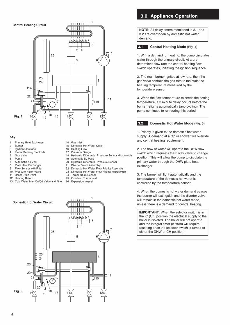
NOTE: All delay timers mentioned in 3.1 and3.2 are overridden by domestic hot waterdemand.
3.1 Central Heating Mode (Fig. 4)
1. With a demand for heating, the pump circulateswater through the primary circuit. At a pre-determined flow rate the central heating flowswitch operates, initiating the ignition sequence.
2. The main burner ignites at low rate, then thegas valve controls the gas rate to maintain theheating temperature measured by thetemperature sensor.
3. When the flow temperature exceeds the settingtemperature, a 3 minute delay occurs before theburner relights automatically (anti-cycling). Thepump continues to run during this period.
3.2 Domestic Hot Water Mode (Fig. 5)
1. Priority is given to the domestic hot watersupply. A demand at a tap or shower will overrideany central heating requirement.
2. The flow of water will operate the DHW flowswitch which requests the 3 way valve to changeposition. This will allow the pump to circulate theprimary water through the DHW plate heatexchanger.
3. The burner will light automatically and thetemperature of the domestic hot water iscontrolled by the temperature sensor.
4. When the domestic hot water demand ceasesthe burner will extinguish and the diverter valvewill remain in the domestic hot water mode,unless there is a demand for central heating.
IMPORTANT: When the selector switch is inthe ‘0’ (Off) position the electrical supply to theboiler is isolated. The boiler will not operateand the integral timer (if fitted) will requireresetting once the selector switch is turned toeither the DHW or CH position.
1
2
4
5 6
7
8
9
10 11
1213141516
17
1819
20
21
22
23
2425
26
3
1 Primary Heat Exchanger2 Burner 3 Ignition Electrode4 Flame Sensing Electrode5 Gas Valve6 Pump7 Automatic Air Vent8 Plate Heat Exchanger9 Flow Sensor with Filter10 Pressure Relief Valve11 Boiler Drain Point12 Heating Return13 Cold Water Inlet On/Off Valve and Filter
14 Gas Inlet15 Domestic Hot Water Outlet16 Heating Flow17 Pressure Gauge18 Hydraulic Differential Pressure Sensor Microswitch19 Automatic By-Pass20 Hydraulic Differential Pressure Sensor21 Diverter Valve Assembly22 Domestic Hot Water Flow Priority Assembly23 Domestic Hot Water Flow Priority Microswitch24 Temperature Sensor25 Overheat Thermostat26 Expansion Vessel
Key
Central Heating Circuit
Domestic Hot Water Circuit
Fig. 4
Fig. 5
1
2
4
5 6
7
8
9
10 11
1213141516
17
1819
20
21
22
23
2425
26
3
4.0 Technical Data
7
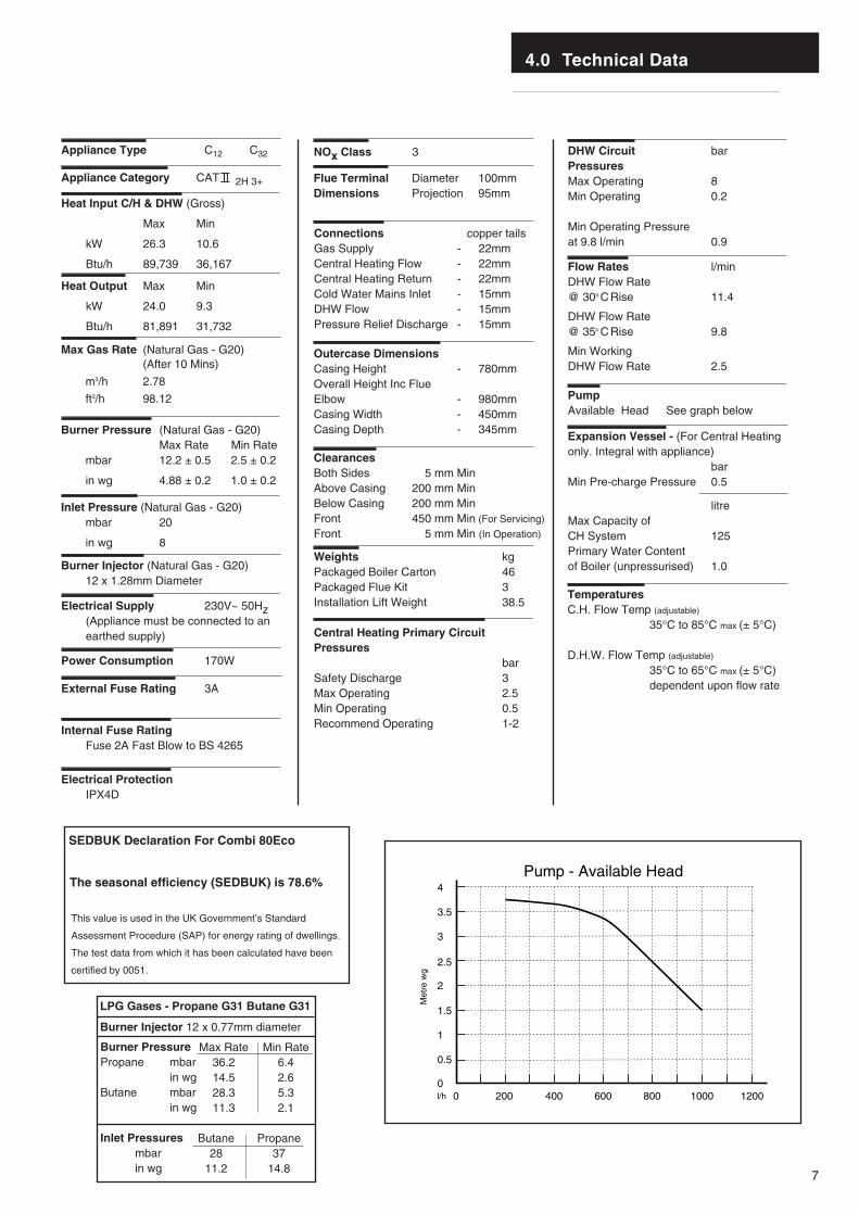
Flue Terminal Diameter 100mmDimensions Projection 95mm
Outercase DimensionsCasing Height - 780mmOverall Height Inc FlueElbow - 980mmCasing Width - 450mmCasing Depth - 345mm
ClearancesBoth Sides 5 mm MinAbove Casing 200 mm MinBelow Casing 200 mm MinFront 450 mm Min (For Servicing)
Front 5 mm Min (In Operation)
Weights kgPackaged Boiler Carton 46Packaged Flue Kit 3Installation Lift Weight 38.5
Central Heating Primary CircuitPressures
barSafety Discharge 3Max Operating 2.5Min Operating 0.5Recommend Operating 1-2
DHW Circuit barPressuresMax Operating 8Min Operating 0.2
Min Operating Pressureat 9.8 l/min 0.9
Flow Rates l/min DHW Flow Rate @ 30o CRise 11.4
DHW Flow Rate@ 35o CRise 9.8
Min WorkingDHW Flow Rate 2.5
PumpAvailable Head See graph below
Expansion Vessel - (For Central Heatingonly. Integral with appliance)
barMin Pre-charge Pressure 0.5
litreMax Capacity of CH System 125Primary Water Contentof Boiler (unpressurised) 1.0
Connections copper tailsGas Supply - 22mmCentral Heating Flow - 22mmCentral Heating Return - 22mmCold Water Mains Inlet - 15mmDHW Flow - 15mmPressure Relief Discharge - 15mm
TemperaturesC.H. Flow Temp (adjustable)
35°C to 85°C max (± 5°C)
D.H.W. Flow Temp (adjustable)
35°C to 65°C max (± 5°C)dependent upon flow rate
Heat Input C/H & DHW (Gross)
Max Min
kW 26.3 10.6
Btu/h 89,739 36,167
Heat Output Max Min
kW 24.0 9.3
Btu/h 81,891 31,732
Electrical Supply 230V~ 50Hz (Appliance must be connected to an earthed supply)
Power Consumption 170W
External Fuse Rating 3A
Internal Fuse Rating Fuse 2A Fast Blow to BS 4265
Appliance Category CAT II 2H 3+
Max Gas Rate (Natural Gas - G20)(After 10 Mins)
m3/h 2.78
ft3/h 98.12
Inlet Pressure (Natural Gas - G20)mbar 20
in wg 8
Burner Injector (Natural Gas - G20)12 x 1.28mm Diameter
Burner Pressure (Natural Gas - G20)Max Rate Min Rate
mbar 12.2 ± 0.5 2.5 ± 0.2
in wg 4.88 ± 0.2 1.0 ± 0.2
0200 400 600 800 1000 1200
0.5
1
1.5
2
2.5
3
3.5
4
Met
re w
g
l/h
Pump - Available Head
0
Appliance Type C12 C32 NOx Class 3
This value is used in the UK Government’s Standard
Assessment Procedure (SAP) for energy rating of dwellings.
The test data from which it has been calculated have been
certified by 0051.
SEDBUK Declaration For Combi 80Eco
The seasonal efficiency (SEDBUK) is 78.6%
Electrical ProtectionIPX4D
LPG Gases - Propane G31 Butane G31
Burner Injector 12 x 0.77mm diameter
Burner PressurePropane mbar
in wgButane mbar
in wg
Inlet Pressuresmbarin wg
Butane28
11.2
Max Rate36.214.528.311.3
Min Rate6.42.65.32.1
Propane37
14.8
5.0 Dimensions and Fixings
8
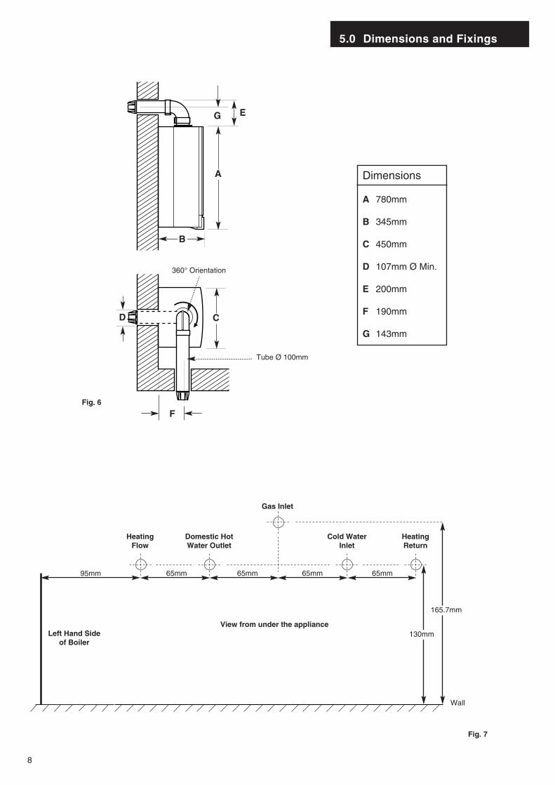
Dimensions
A 780mm
B 345mm
C 450mm
D 107mm Ø Min.
E 200mm
F 190mm
G 143mm
360° Orientation
Tube Ø 100mm
D C
B
A
EG
F
65mm 65mm 65mm 65mm
Wall
View from under the appliance
Gas Inlet
Heating Flow
Domestic HotWater Outlet
Cold Water Inlet
Heating Return
130mm
165.7mm
95mm
Left Hand Sideof Boiler
Fig. 6
Fig. 7
6.0 System Details
9
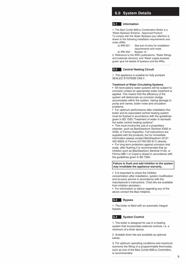
6.1 Information
1. The Baxi Combi 80Eco Combination Boiler is a‘Water Byelaws Scheme - Approved Product’.To comply with the Water Byelaws your attention isdrawn to the following installation requirements andnotes (IRN).
a) IRN 001 - See text of entry for installation requirements and notes.
b) IRN 302 - Byelaw 14.2. Reference to the WRC publications, ‘Water fittingsand materials directory’ and ‘Water supply byelawsguide’ give full details of byelaws and the IRNs.
6.2 Central Heating Circuit
1. The appliance is suitable for fully pumpedSEALED SYSTEMS ONLY.
Treatment of Water Circulating Systems• All recirculatory water systems will be subject tocorrosion unless an appropriate water treatment isapplied. This means that the efficiency of thesystem will deteriorate as corrosion sludgeaccumulates within the system, risking damage topump and valves, boiler noise and circulationproblems.• For optimum performance after installation thisboiler and its associated central heating systemmust be flushed in accordance with the guidelinesgiven in BS 7593 “Treatment of water in domestichot water central heating systems”.• This must involve the use of a proprietarycleanser, such as BetzDearborn Sentinel X300 orX400, or Fernox Superfloc. Full instructions aresupplied with the products, but for immediateinformation please contact BetzDearborn (0151420 9563) or Fernox (01799 550 811) directly.• For long term protection against corrosion andscale, after flushing it is recommended that aninhibitor such as BetzDearborn Sentinel X100, orFernox MB-1 or Copal is dosed in accordance withthe guidelines given in BS 7593.
Failure to flush and add inhibitor to the systemmay invalidate the appliance warranty.
• It is important to check the inhibitorconcentration after installation, system modificationand at every service in accordance with themanufacturer’s instructions. (Test kits are availablefrom inhibitor stockists.)• For information or advice regarding any of the above contact the Baxi Helpline.
6.3 Bypass
1. The boiler is fitted with an automatic integralbypass.
6.4 System Control
1. The boiler is designed for use in a heatingsystem that incorporates external controls, i.e. aminimum of a timer device.
2. Suitable timer kits are available as optionalextras.
3. For optimum operating conditions and maximumeconomy the fitting of a programmable thermostat,such as one of the Baxi Combi 80Eco Controllers,is recommended.
StopValve
DoubleCheckValve
DHWMainsInlet
CHReturn
TemporaryHose
6.0 System Details
10
6.5 System Filling and Pressurising
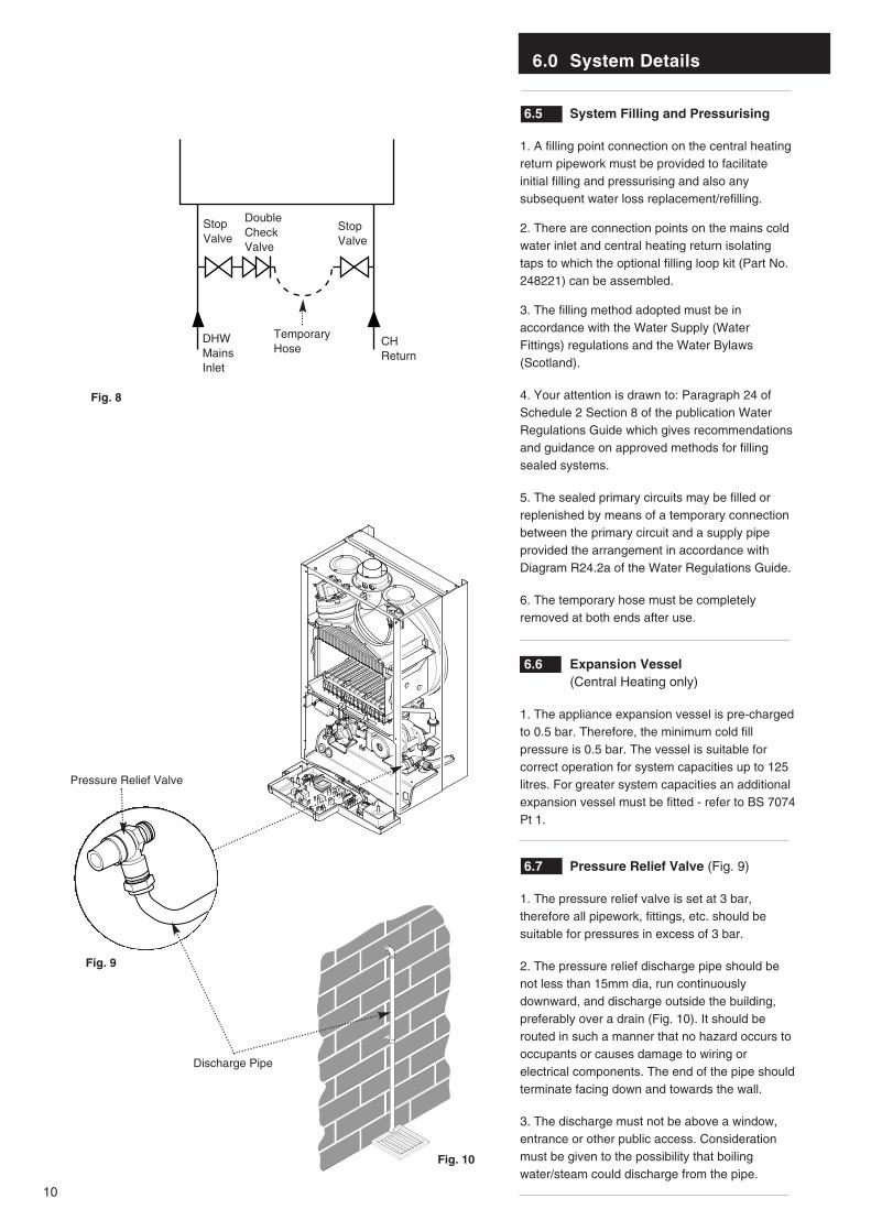
1. A filling point connection on the central heatingreturn pipework must be provided to facilitateinitial filling and pressurising and also anysubsequent water loss replacement/refilling.
2. There are connection points on the mains coldwater inlet and central heating return isolatingtaps to which the optional filling loop kit (Part No.248221) can be assembled.
3. The filling method adopted must be inaccordance with the Water Supply (WaterFittings) regulations and the Water Bylaws(Scotland).
4. Your attention is drawn to: Paragraph 24 ofSchedule 2 Section 8 of the publication WaterRegulations Guide which gives recommendationsand guidance on approved methods for fillingsealed systems.
5. The sealed primary circuits may be filled orreplenished by means of a temporary connectionbetween the primary circuit and a supply pipeprovided the arrangement in accordance withDiagram R24.2a of the Water Regulations Guide.
6. The temporary hose must be completelyremoved at both ends after use.
6.6 Expansion Vessel (Central Heating only)
1. The appliance expansion vessel is pre-chargedto 0.5 bar. Therefore, the minimum cold fillpressure is 0.5 bar. The vessel is suitable forcorrect operation for system capacities up to 125litres. For greater system capacities an additionalexpansion vessel must be fitted - refer to BS 7074Pt 1.
6.7 Pressure Relief Valve (Fig. 9)
1. The pressure relief valve is set at 3 bar,therefore all pipework, fittings, etc. should besuitable for pressures in excess of 3 bar.
2. The pressure relief discharge pipe should benot less than 15mm dia, run continuouslydownward, and discharge outside the building,preferably over a drain (Fig. 10). It should berouted in such a manner that no hazard occurs tooccupants or causes damage to wiring orelectrical components. The end of the pipe shouldterminate facing down and towards the wall.
3. The discharge must not be above a window,entrance or other public access. Considerationmust be given to the possibility that boilingwater/steam could discharge from the pipe.
Fig. 8
Fig. 9
Fig. 10
Pressure Relief Valve
Discharge Pipe
StopValve
6.0 System Details
11
6.8 Domestic Hot Water Circuit
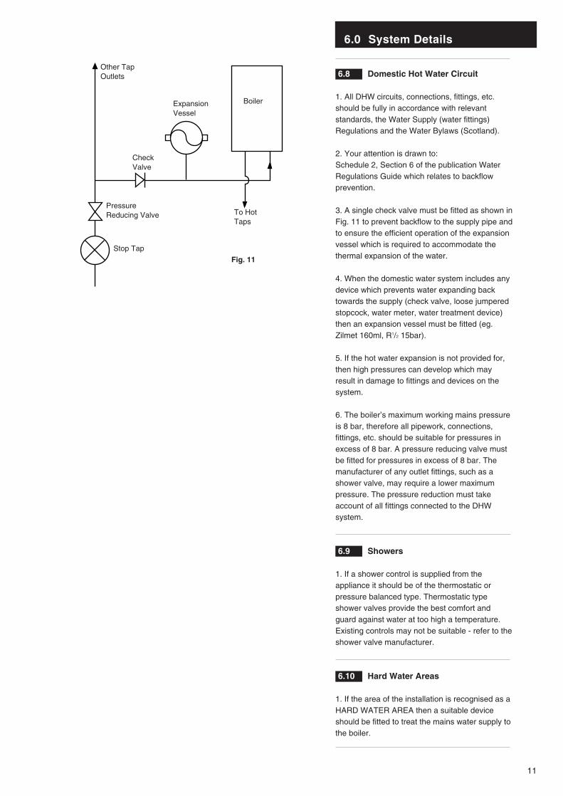
1. All DHW circuits, connections, fittings, etc.should be fully in accordance with relevantstandards, the Water Supply (water fittings)Regulations and the Water Bylaws (Scotland).
2. Your attention is drawn to: Schedule 2, Section 6 of the publication WaterRegulations Guide which relates to backflowprevention.
3. A single check valve must be fitted as shown inFig. 11 to prevent backflow to the supply pipe andto ensure the efficient operation of the expansionvessel which is required to accommodate thethermal expansion of the water.
4. When the domestic water system includes anydevice which prevents water expanding backtowards the supply (check valve, loose jumperedstopcock, water meter, water treatment device)then an expansion vessel must be fitted (eg.Zilmet 160ml, R1/2 15bar).
5. If the hot water expansion is not provided for,then high pressures can develop which mayresult in damage to fittings and devices on thesystem.
6. The boiler’s maximum working mains pressureis 8 bar, therefore all pipework, connections,fittings, etc. should be suitable for pressures inexcess of 8 bar. A pressure reducing valve mustbe fitted for pressures in excess of 8 bar. Themanufacturer of any outlet fittings, such as ashower valve, may require a lower maximumpressure. The pressure reduction must takeaccount of all fittings connected to the DHWsystem.
6.9 Showers
1. If a shower control is supplied from theappliance it should be of the thermostatic orpressure balanced type. Thermostatic typeshower valves provide the best comfort andguard against water at too high a temperature.Existing controls may not be suitable - refer to theshower valve manufacturer.
6.10 Hard Water Areas
1. If the area of the installation is recognised as aHARD WATER AREA then a suitable deviceshould be fitted to treat the mains water supply tothe boiler.
Boiler
Other TapOutlets
ExpansionVessel
To HotTaps
CheckValve
PressureReducing Valve
Stop Tap
Fig. 11
7.0 Site Requirements
12
7.1 Information
1. The installation must be carried out by a CORGIRegistered Installer or other registered competentperson and be in accordance with the relevantrequirements of the current GAS SAFETY (Installationand Use) REGULATIONS, the BUILDING REGULATIONS
(Scotland)(Consolidation), the LOCAL BUILDING
REGULATIONS, the current I.E.E. WIRING REGULATIONS
and the bye laws of the LOCAL WATER UNDERTAKING.Where no specific instruction is given referenceshould be made to the relevant BRITISHSTANDARD CODES OF PRACTICE. For Irelandinstall in accordance with IS 813 “INSTALLATION OF
GAS APPLIANCES”.
7.2 B.S. Codes of Practice
Standard ScopeBS 6891 Gas Installation.BS 5546 Installation of hot water supplies for
domestic purposes.BS 5449 Part 1 Forced circulation hot water systems.BS 6798 Installation of gas fired hot water boilers.BS 5440 Part 1 Flues.BS 5440 Part 2 Ventilation.BS 7074 Expansion vessels and ancillary
equipment for sealed water systems.BS 7593 Treatment of water in domestic hot water
central heating systems.
WARNING - The addition of anything that mayinterfere with the normal operation of theappliance without the express written permissionof Baxi UK Limited could invalidate the appliancewarranty and infringe the GAS SAFETY
(Installation and Use) REGULATIONS.
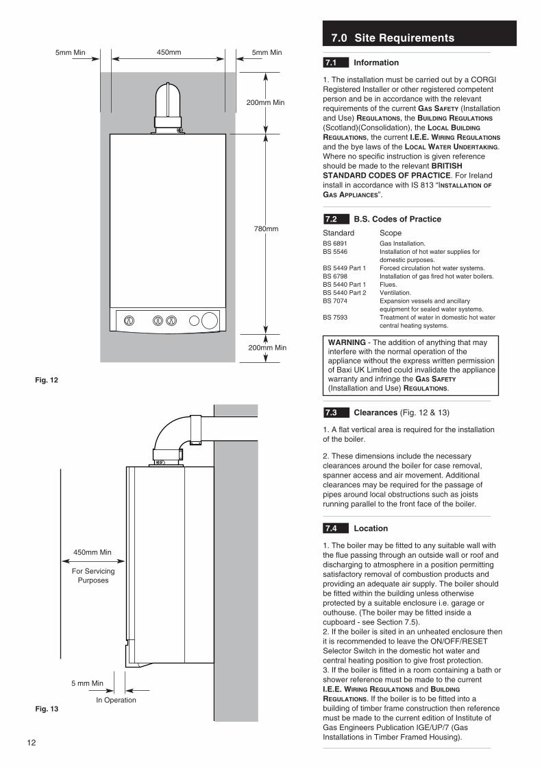
7.3 Clearances (Fig. 12 & 13)
1. A flat vertical area is required for the installationof the boiler.
2. These dimensions include the necessaryclearances around the boiler for case removal,spanner access and air movement. Additionalclearances may be required for the passage ofpipes around local obstructions such as joistsrunning parallel to the front face of the boiler.
7.4 Location
1. The boiler may be fitted to any suitable wall withthe flue passing through an outside wall or roof anddischarging to atmosphere in a position permittingsatisfactory removal of combustion products andproviding an adequate air supply. The boiler shouldbe fitted within the building unless otherwiseprotected by a suitable enclosure i.e. garage orouthouse. (The boiler may be fitted inside acupboard - see Section 7.5).2. If the boiler is sited in an unheated enclosure thenit is recommended to leave the ON/OFF/RESETSelector Switch in the domestic hot water andcentral heating position to give frost protection. 3. If the boiler is fitted in a room containing a bath orshower reference must be made to the currentI.E.E. WIRING REGULATIONS and BUILDING
REGULATIONS. If the boiler is to be fitted into abuilding of timber frame construction then referencemust be made to the current edition of Institute ofGas Engineers Publication IGE/UP/7 (GasInstallations in Timber Framed Housing).
200mm Min
780mm
450mm
200mm Min
5mm Min5mm Min
5 mm Min
450mm Min
For ServicingPurposes
Fig. 12
Fig. 13In Operation
7.0 Site Requirements
13
7.5 Ventilation of Compartments
1. Where the appliance is installed in a cupboardor compartment, no air vents are required.
2. BS 5440: Part 2 refers to room sealedappliances installed in compartments. Theappliance will run sufficiently cool withoutventilation.
7.6 Gas Supply
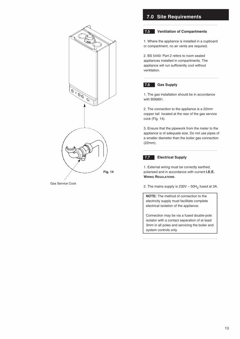
1. The gas installation should be in accordancewith BS6891.
2. The connection to the appliance is a 22mmcopper tail located at the rear of the gas servicecock (Fig. 14).
3. Ensure that the pipework from the meter to theappliance is of adequate size. Do not use pipes ofa smaller diameter than the boiler gas connection(22mm).
7.7 Electrical Supply
1. External wiring must be correctly earthed,polarised and in accordance with current I.E.E.WIRING REGULATIONS.
2. The mains supply is 230V ~ 50Hz fused at 3A.
NOTE: The method of connection to theelectricity supply must facilitate completeelectrical isolation of the appliance.
Connection may be via a fused double-poleisolator with a contact separation of at least3mm in all poles and servicing the boiler andsystem controls only.
Fig. 14
Gas Service Cock
7.0 Site Requirements
14
Fig. 16
7.8 Flue
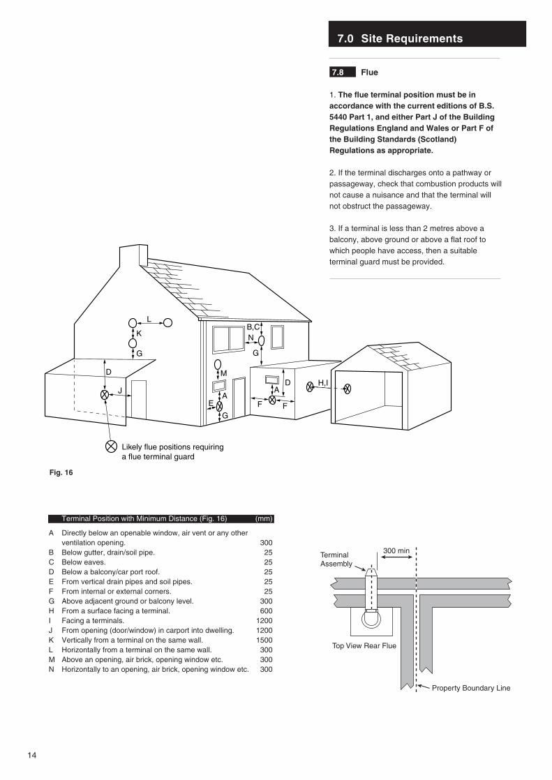
1. The flue terminal position must be inaccordance with the current editions of B.S.5440 Part 1, and either Part J of the BuildingRegulations England and Wales or Part F ofthe Building Standards (Scotland)Regulations as appropriate.
2. If the terminal discharges onto a pathway orpassageway, check that combustion products willnot cause a nuisance and that the terminal willnot obstruct the passageway.
3. If a terminal is less than 2 metres above abalcony, above ground or above a flat roof towhich people have access, then a suitableterminal guard must be provided.
Terminal Position with Minimum Distance (Fig. 16) (mm)
A Directly below an openable window, air vent or any other ventilation opening. 300
B Below gutter, drain/soil pipe. 25C Below eaves. 25D Below a balcony/car port roof. 25E From vertical drain pipes and soil pipes. 25F From internal or external corners. 25G Above adjacent ground or balcony level. 300H From a surface facing a terminal. 600I Facing a terminals. 1200J From opening (door/window) in carport into dwelling. 1200K Vertically from a terminal on the same wall. 1500L Horizontally from a terminal on the same wall. 300M Above an opening, air brick, opening window etc. 300N Horizontally to an opening, air brick, opening window etc. 300
L
G
G
E
J
D
K
G
AA
D
F
H,I
B,C
F
Likely flue positions requiring a flue terminal guard
M
N
300 minTerminalAssembly
Top View Rear Flue
Property Boundary Line
7.0 Site Requirements
15
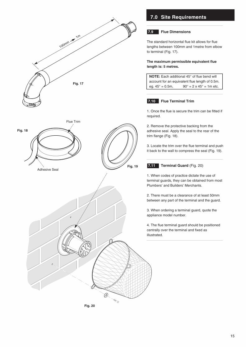
7.9 Flue Dimensions
The standard horizontal flue kit allows for fluelengths between 100mm and 1metre from elbowto terminal (Fig. 17).
The maximum permissible equivalent fluelength is: 5 metres.
NOTE: Each additional 45° of flue bend willaccount for an equivalent flue length of 0.5m.eg. 45° = 0.5m, 90° = 2 x 45° = 1m etc.
7.10 Flue Terminal Trim
1. Once the flue is secure the trim can be fitted ifrequired.
2. Remove the protective backing from theadhesive seal. Apply the seal to the rear of thetrim flange (Fig. 18).
3. Locate the trim over the flue terminal and pushit back to the wall to compress the seal (Fig. 19).
7.11 Terminal Guard (Fig. 20)
1. When codes of practice dictate the use ofterminal guards, they can be obtained from mostPlumbers’ and Builders’ Merchants.
2. There must be a clearance of at least 50mmbetween any part of the terminal and the guard.
3. When ordering a terminal guard, quote theappliance model number.
4. The flue terminal guard should be positionedcentrally over the terminal and fixed asillustrated.
Fig. 20
100mm
1m
Fig. 19
Flue Trim
Adhesive Seal
Fig. 17
Fig. 18
16
7.0 Site Requirements
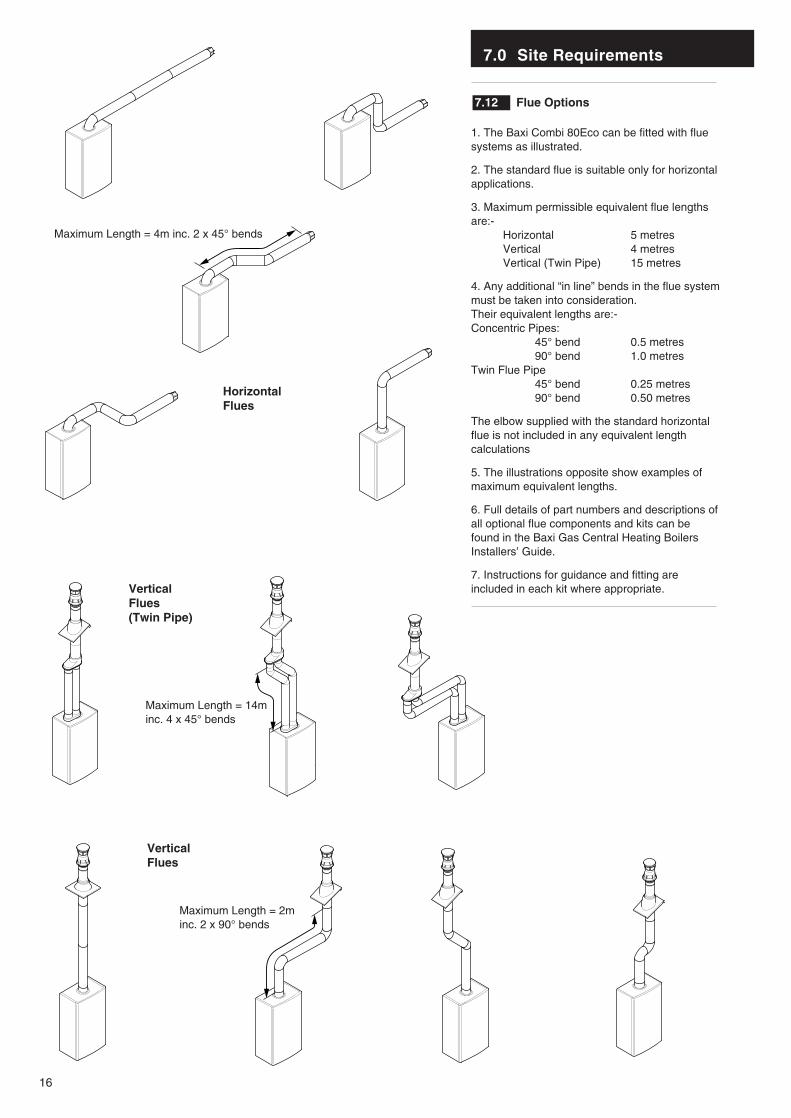
7.12 Flue Options
1. The Baxi Combi 80Eco can be fitted with fluesystems as illustrated.
2. The standard flue is suitable only for horizontalapplications.
3. Maximum permissible equivalent flue lengthsare:-
Horizontal 5 metresVertical 4 metresVertical (Twin Pipe) 15 metres
4. Any additional “in line” bends in the flue systemmust be taken into consideration. Their equivalent lengths are:-Concentric Pipes:
45° bend 0.5 metres90° bend 1.0 metres
Twin Flue Pipe45° bend 0.25 metres90° bend 0.50 metres
The elbow supplied with the standard horizontalflue is not included in any equivalent lengthcalculations
5. The illustrations opposite show examples ofmaximum equivalent lengths.
6. Full details of part numbers and descriptions ofall optional flue components and kits can befound in the Baxi Gas Central Heating BoilersInstallers’ Guide.
7. Instructions for guidance and fitting areincluded in each kit where appropriate.
HorizontalFlues
VerticalFlues
VerticalFlues(Twin Pipe)
Maximum Length = 4m inc. 2 x 45° bends
Maximum Length = 14m inc. 4 x 45° bends
Maximum Length = 2m inc. 2 x 90° bends
8.0 Installation
17
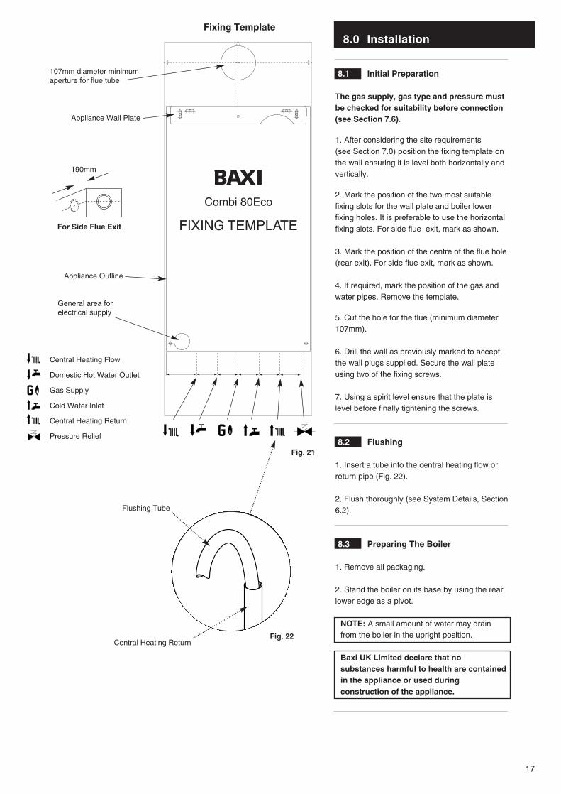
8.1 Initial Preparation
The gas supply, gas type and pressure mustbe checked for suitability before connection(see Section 7.6).
1. After considering the site requirements (see Section 7.0) position the fixing template onthe wall ensuring it is level both horizontally andvertically.
2. Mark the position of the two most suitablefixing slots for the wall plate and boiler lowerfixing holes. It is preferable to use the horizontalfixing slots. For side flue exit, mark as shown.
3. Mark the position of the centre of the flue hole(rear exit). For side flue exit, mark as shown.
4. If required, mark the position of the gas andwater pipes. Remove the template.
5. Cut the hole for the flue (minimum diameter107mm).
6. Drill the wall as previously marked to acceptthe wall plugs supplied. Secure the wall plateusing two of the fixing screws.
7. Using a spirit level ensure that the plate islevel before finally tightening the screws.
8.2 Flushing
1. Insert a tube into the central heating flow orreturn pipe (Fig. 22).
2. Flush thoroughly (see System Details, Section6.2).
8.3 Preparing The Boiler
1. Remove all packaging.
2. Stand the boiler on its base by using the rearlower edge as a pivot.
NOTE: A small amount of water may drainfrom the boiler in the upright position.
Baxi UK Limited declare that nosubstances harmful to health are containedin the appliance or used duringconstruction of the appliance.
Fig. 21
Fig. 22
Combi 80Eco
FIXING TEMPLATE
107mm diameter minimumaperture for flue tube
Fixing Template
General area forelectrical supply
Appliance Outline
Central Heating Flow
Domestic Hot Water Outlet
Gas Supply
Cold Water Inlet
Central Heating Return
Pressure Relief
Appliance Wall Plate
190mm
For Side Flue Exit
Central Heating Return
Flushing Tube
8.0 Installation
18
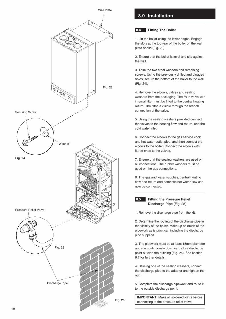
8.4 Fitting The Boiler
1. Lift the boiler using the lower edges. Engagethe slots at the top rear of the boiler on the wallplate hooks (Fig. 23).
2. Ensure that the boiler is level and sits againstthe wall.
3. Take the two steel washers and remainingscrews. Using the previously drilled and pluggedholes, secure the bottom of the boiler to the wall(Fig. 24).
4. Remove the elbows, valves and sealingwashers from the packaging. The 3/4 in valve withinternal filter must be fitted to the central heatingreturn. The filter is visible through the branchconnection of the valve.
5. Using the sealing washers provided connectthe valves to the heating flow and return, and thecold water inlet.
6. Connect the elbows to the gas service cockand hot water outlet pipe, and then connect theelbows to the boiler. Connect the elbows withflared ends to the valves.
7. Ensure that the sealing washers are used onall connections. The rubber washers must beused on the gas connections.
8. The gas and water supplies, central heatingflow and return and domestic hot water flow cannow be connected.
8.5 Fitting the Pressure Relief Discharge Pipe (Fig. 25)
1. Remove the discharge pipe from the kit.
2. Determine the routing of the discharge pipe inthe vicinity of the boiler. Make up as much of thepipework as is practical, including the dischargepipe supplied.
3. The pipework must be at least 15mm diameterand run continuously downwards to a dischargepoint outside the building (Fig. 26). See section6.7 for further details.
4. Utilising one of the sealing washers, connectthe discharge pipe to the adaptor and tighten thenut.
5. Complete the discharge pipework and route itto the outside discharge point.
IMPORTANT: Make all soldered joints beforeconnecting to the pressure relief valve.
Fig. 25
Fig. 26
Fig. 23
Fig. 24
Pressure Relief Valve
Securing Screw
Washer
Wall Plate
Discharge Pipe
8.0 Installation
19
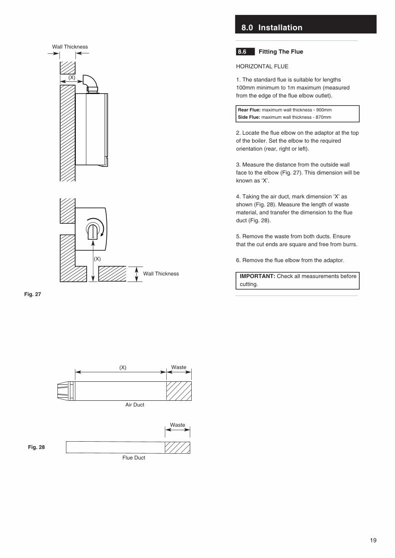
8.6 Fitting The Flue
HORIZONTAL FLUE
1. The standard flue is suitable for lengths100mm minimum to 1m maximum (measuredfrom the edge of the flue elbow outlet).
Rear Flue: maximum wall thickness - 900mm
Side Flue: maximum wall thickness - 870mm
2. Locate the flue elbow on the adaptor at the topof the boiler. Set the elbow to the requiredorientation (rear, right or left).
3. Measure the distance from the outside wallface to the elbow (Fig. 27). This dimension will beknown as ‘X’.
4. Taking the air duct, mark dimension ‘X’ asshown (Fig. 28). Measure the length of wastematerial, and transfer the dimension to the flueduct (Fig. 28).
5. Remove the waste from both ducts. Ensurethat the cut ends are square and free from burrs.
6. Remove the flue elbow from the adaptor.
IMPORTANT: Check all measurements beforecutting.
Wall Thickness
(X)
Wall Thickness
(X)
Fig. 27
Waste(X)
Waste
Fig. 28
Air Duct
Flue Duct
8.0 Installation
20
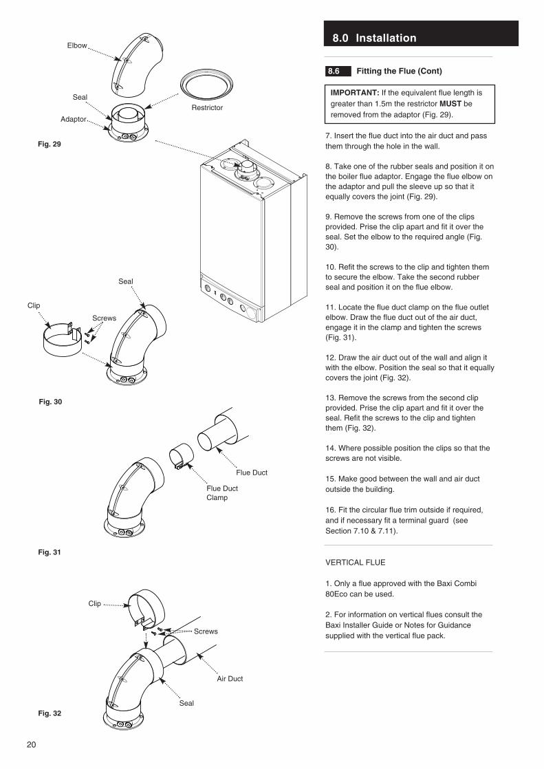
8.6 Fitting the Flue (Cont)
IMPORTANT: If the equivalent flue length isgreater than 1.5m the restrictor MUST beremoved from the adaptor (Fig. 29).
7. Insert the flue duct into the air duct and passthem through the hole in the wall.
8. Take one of the rubber seals and position it onthe boiler flue adaptor. Engage the flue elbow onthe adaptor and pull the sleeve up so that itequally covers the joint (Fig. 29).
9. Remove the screws from one of the clipsprovided. Prise the clip apart and fit it over theseal. Set the elbow to the required angle (Fig.30).
10. Refit the screws to the clip and tighten themto secure the elbow. Take the second rubberseal and position it on the flue elbow.
11. Locate the flue duct clamp on the flue outletelbow. Draw the flue duct out of the air duct,engage it in the clamp and tighten the screws(Fig. 31).
12. Draw the air duct out of the wall and align itwith the elbow. Position the seal so that it equallycovers the joint (Fig. 32).
13. Remove the screws from the second clipprovided. Prise the clip apart and fit it over theseal. Refit the screws to the clip and tightenthem (Fig. 32).
14. Where possible position the clips so that thescrews are not visible.
15. Make good between the wall and air ductoutside the building.
16. Fit the circular flue trim outside if required,and if necessary fit a terminal guard (seeSection 7.10 & 7.11).
VERTICAL FLUE
1. Only a flue approved with the Baxi Combi80Eco can be used.
2. For information on vertical flues consult theBaxi Installer Guide or Notes for Guidancesupplied with the vertical flue pack.
Fig. 29
Fig. 30
Fig. 31
Fig. 32
Elbow
RestrictorSeal
Adaptor
Seal
Clip
Screws
Flue DuctClamp
Flue Duct
Air Duct
Seal
Clip
Screws
8.0 Installation
21
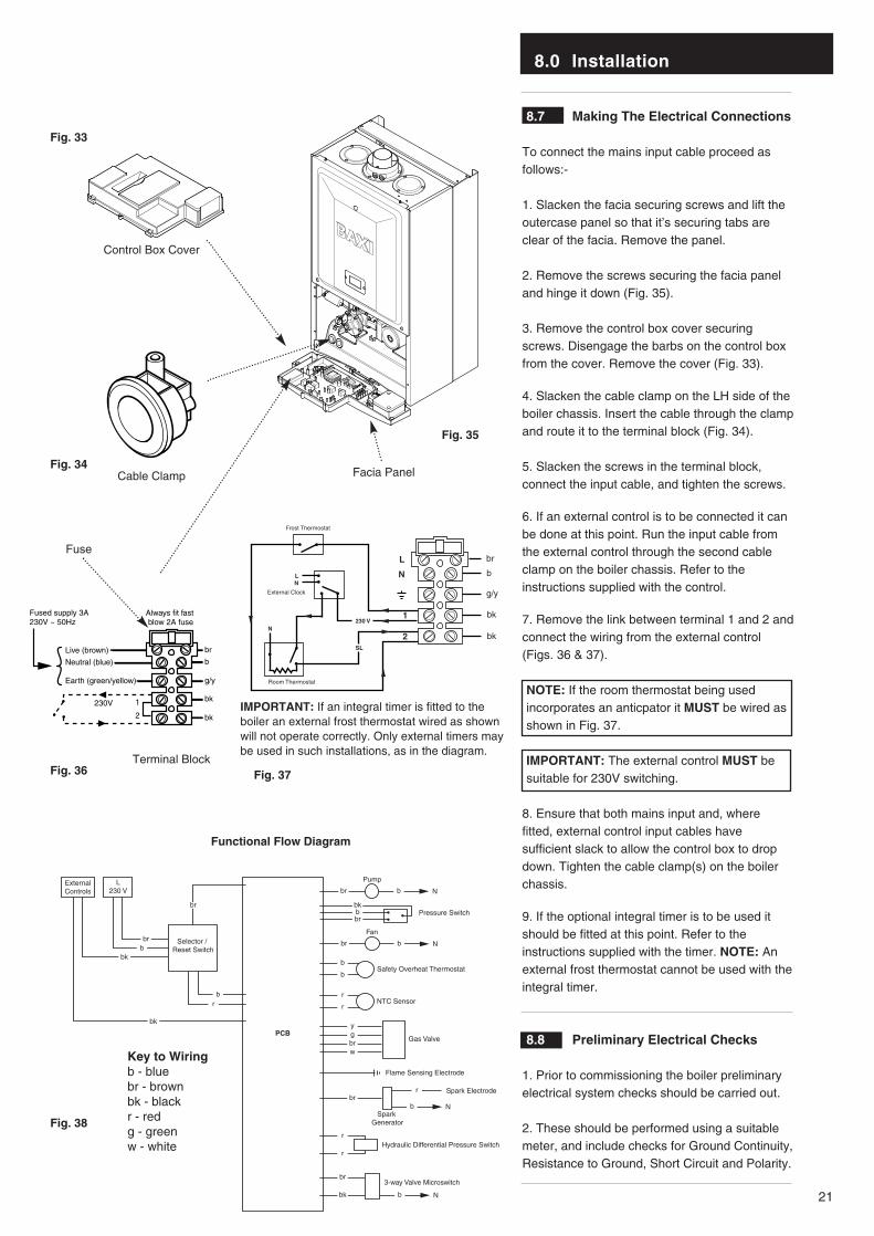
8.7 Making The Electrical Connections
To connect the mains input cable proceed asfollows:-
1. Slacken the facia securing screws and lift theoutercase panel so that it’s securing tabs areclear of the facia. Remove the panel.
2. Remove the screws securing the facia paneland hinge it down (Fig. 35).
3. Remove the control box cover securingscrews. Disengage the barbs on the control boxfrom the cover. Remove the cover (Fig. 33).
4. Slacken the cable clamp on the LH side of theboiler chassis. Insert the cable through the clampand route it to the terminal block (Fig. 34).
5. Slacken the screws in the terminal block,connect the input cable, and tighten the screws.
6. If an external control is to be connected it canbe done at this point. Run the input cable fromthe external control through the second cableclamp on the boiler chassis. Refer to theinstructions supplied with the control.
7. Remove the link between terminal 1 and 2 andconnect the wiring from the external control(Figs. 36 & 37).
NOTE: If the room thermostat being usedincorporates an anticpator it MUST be wired asshown in Fig. 37.
IMPORTANT: The external control MUST besuitable for 230V switching.
8. Ensure that both mains input and, wherefitted, external control input cables havesufficient slack to allow the control box to dropdown. Tighten the cable clamp(s) on the boilerchassis.
9. If the optional integral timer is to be used itshould be fitted at this point. Refer to theinstructions supplied with the timer. NOTE: Anexternal frost thermostat cannot be used with theintegral timer.
8.8 Preliminary Electrical Checks
1. Prior to commissioning the boiler preliminaryelectrical system checks should be carried out.
2. These should be performed using a suitablemeter, and include checks for Ground Continuity,Resistance to Ground, Short Circuit and Polarity.
Always fit fast blow 2A fuse
Fused supply 3A230V ~ 50Hz
Live (brown)
Neutral (blue)
Earth (green/yellow)
1
2
230V
br
b
g/y
bk
bk
b
br
bk
bk
g/y
1
N
L
Frost Thermostat
Room Thermostat
External Clock
2N
230 V
NL
SL
L230 V
Selector / Reset Switch
ExternalControls Nbr b
Pump
Hydraulic Differential Pressure Switchr
r
3-way Valve Microswitchbr
bk
Safety Overheat Thermostatb
b
NTC Sensorr
r
Gas Valve
Spark Electrode
Spark Generator
Flame Sensing Electrode
Nbr b
Fan
Nb
Nb
ygbrw
brr
Pressure Switchbbr
bk
PCB
b
bbr
br
r
bk
bk
Fig. 34
Fig. 33
Fig. 36 Fig. 37
Fig. 38
Fig. 35
Terminal Block
Fuse
Cable Clamp
Control Box Cover
Facia Panel
Functional Flow Diagram
Key to Wiringb - bluebr - brownbk - blackr - redg - greenw - white
IMPORTANT: If an integral timer is fitted to theboiler an external frost thermostat wired as shownwill not operate correctly. Only external timers maybe used in such installations, as in the diagram.
9.0 Commissioning the Boiler
22
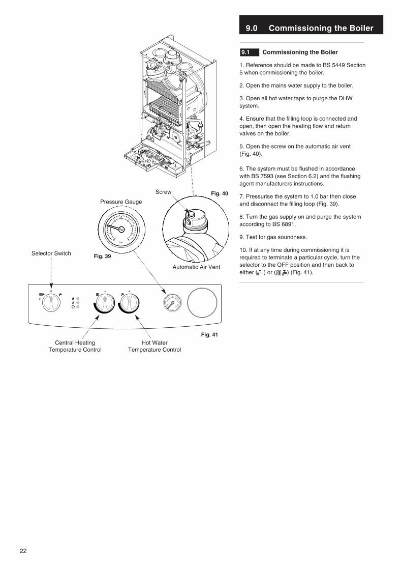
9.1 Commissioning the Boiler
1. Reference should be made to BS 5449 Section5 when commissioning the boiler.
2. Open the mains water supply to the boiler.
3. Open all hot water taps to purge the DHWsystem.
4. Ensure that the filling loop is connected andopen, then open the heating flow and returnvalves on the boiler.
5. Open the screw on the automatic air vent (Fig. 40).
6. The system must be flushed in accordancewith BS 7593 (see Section 6.2) and the flushingagent manufacturers instructions.
7. Pressurise the system to 1.0 bar then closeand disconnect the filling loop (Fig. 39).
8. Turn the gas supply on and purge the systemaccording to BS 6891.
9. Test for gas soundness.
10. If at any time during commissioning it isrequired to terminate a particular cycle, turn theselector to the OFF position and then back toeither ( ) or ( ) (Fig. 41).
Automatic Air Vent
Pressure Gauge
Screw
2
1
0 4
3
bar
Selector Switch
Central Heating Temperature Control
Hot Water Temperature Control
Fig. 40
Fig. 41
Fig. 39
2
1
0 4
3
bar
9.0 Commissioning the Boiler
23
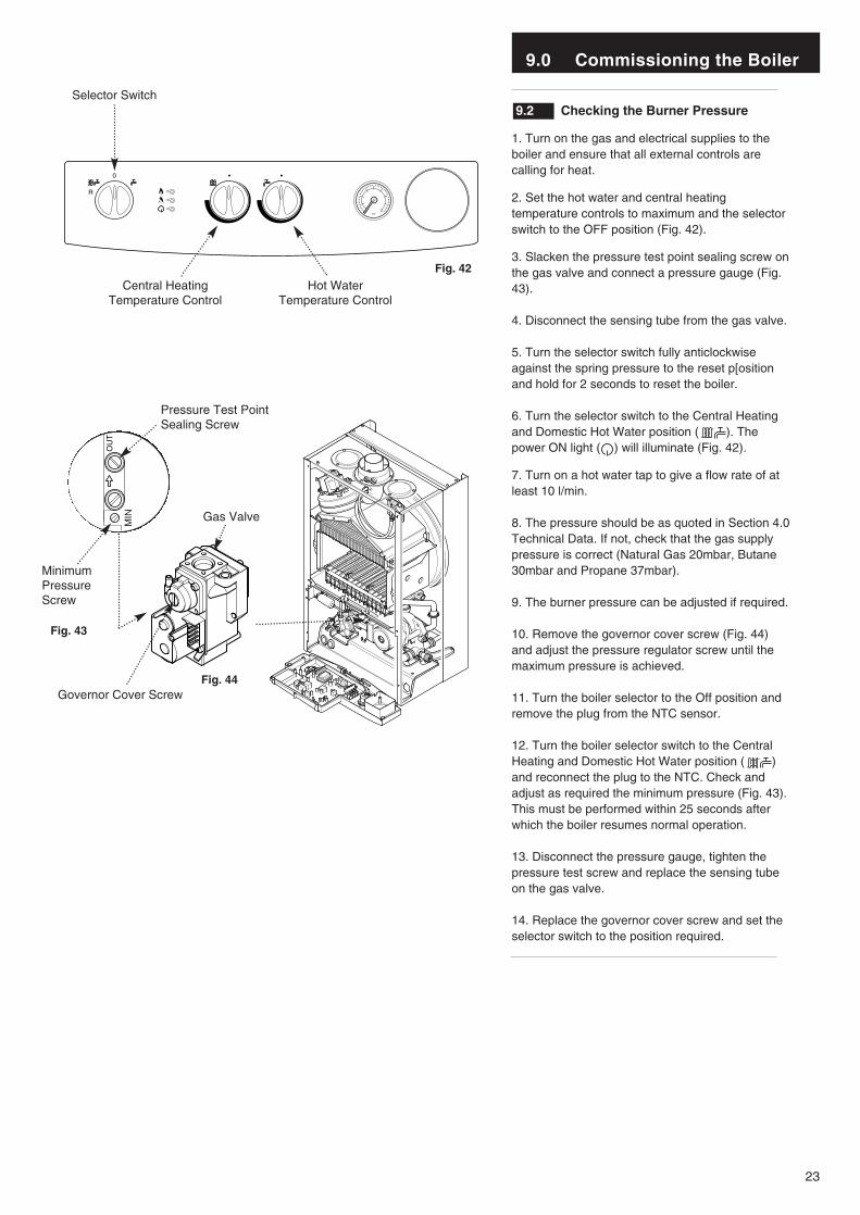
9.2 Checking the Burner Pressure
1. Turn on the gas and electrical supplies to theboiler and ensure that all external controls arecalling for heat.
2. Set the hot water and central heatingtemperature controls to maximum and the selectorswitch to the OFF position (Fig. 42).
3. Slacken the pressure test point sealing screw onthe gas valve and connect a pressure gauge (Fig.43).
4. Disconnect the sensing tube from the gas valve.
5. Turn the selector switch fully anticlockwiseagainst the spring pressure to the reset p[ositionand hold for 2 seconds to reset the boiler.
6. Turn the selector switch to the Central Heatingand Domestic Hot Water position ( ). Thepower ON light ( ) will illuminate (Fig. 42).
7. Turn on a hot water tap to give a flow rate of atleast 10 l/min.
8. The pressure should be as quoted in Section 4.0Technical Data. If not, check that the gas supplypressure is correct (Natural Gas 20mbar, Butane30mbar and Propane 37mbar).
9. The burner pressure can be adjusted if required.
10. Remove the governor cover screw (Fig. 44)and adjust the pressure regulator screw until themaximum pressure is achieved.
11. Turn the boiler selector to the Off position andremove the plug from the NTC sensor.
12. Turn the boiler selector switch to the CentralHeating and Domestic Hot Water position ( )and reconnect the plug to the NTC. Check andadjust as required the minimum pressure (Fig. 43).This must be performed within 25 seconds afterwhich the boiler resumes normal operation.
13. Disconnect the pressure gauge, tighten thepressure test screw and replace the sensing tubeon the gas valve.
14. Replace the governor cover screw and set theselector switch to the position required.
OU
T
MIN
Pressure Test Point Sealing Screw
Governor Cover Screw
Gas Valve
Central Heating Temperature Control
Hot Water Temperature Control
Fig. 42
Fig. 43
Fig. 44
2
1
0 4
3
bar
Selector Switch
MinimumPressureScrew
10.0 Completion
24
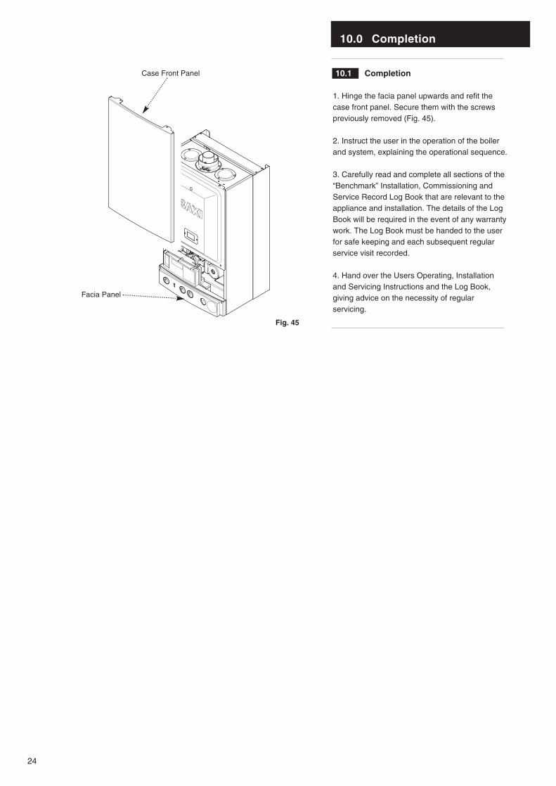
10.1 Completion
1. Hinge the facia panel upwards and refit thecase front panel. Secure them with the screwspreviously removed (Fig. 45).
2. Instruct the user in the operation of the boilerand system, explaining the operational sequence.
3. Carefully read and complete all sections of the“Benchmark” Installation, Commissioning andService Record Log Book that are relevant to theappliance and installation. The details of the LogBook will be required in the event of any warrantywork. The Log Book must be handed to the userfor safe keeping and each subsequent regularservice visit recorded.
4. Hand over the Users Operating, Installationand Servicing Instructions and the Log Book,giving advice on the necessity of regularservicing.
Fig. 45
Facia Panel
Case Front Panel
11.0 Servicing the Boiler
25
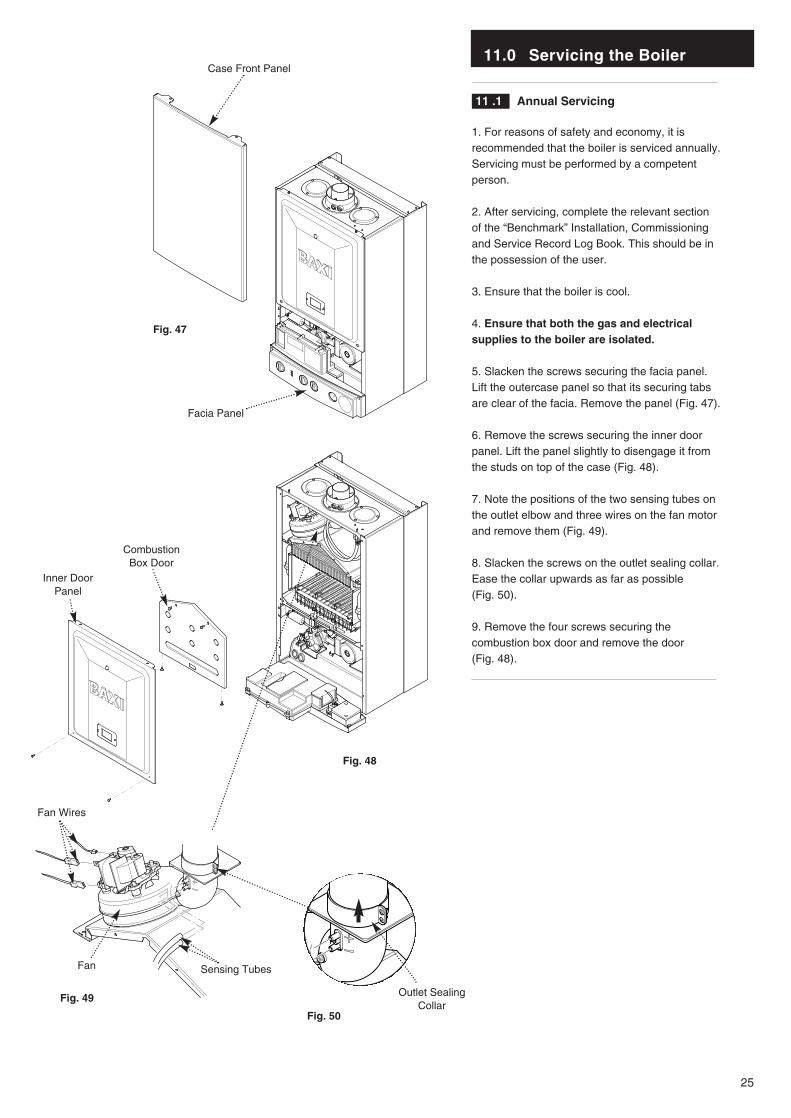
11 .1 Annual Servicing
1. For reasons of safety and economy, it isrecommended that the boiler is serviced annually.Servicing must be performed by a competentperson.
2. After servicing, complete the relevant sectionof the “Benchmark” Installation, Commissioningand Service Record Log Book. This should be inthe possession of the user.
3. Ensure that the boiler is cool.
4. Ensure that both the gas and electricalsupplies to the boiler are isolated.
5. Slacken the screws securing the facia panel.Lift the outercase panel so that its securing tabsare clear of the facia. Remove the panel (Fig. 47).
6. Remove the screws securing the inner doorpanel. Lift the panel slightly to disengage it fromthe studs on top of the case (Fig. 48).
7. Note the positions of the two sensing tubes onthe outlet elbow and three wires on the fan motorand remove them (Fig. 49).
8. Slacken the screws on the outlet sealing collar.Ease the collar upwards as far as possible(Fig. 50).
9. Remove the four screws securing thecombustion box door and remove the door(Fig. 48).
Fig. 47
Fig. 48
Fig. 49
Fig. 50
Facia Panel
Fan Wires
Fan Sensing Tubes
Outlet SealingCollar
Case Front Panel
CombustionBox Door
Inner DoorPanel
11.0 Servicing the Boiler
26
11.1 Annual Servicing (Cont)
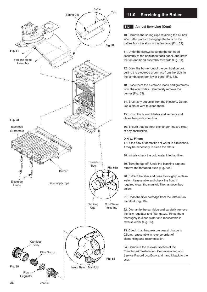
10. Remove the spring clips retaining the air boxside baffle plates. Disengage the tabs on thebaffles from the slots in the fan hood (Fig. 52).
11. Undo the screws securing the fan hoodassembly to the appliance back panel, and drawthe fan and hood assembly forwards (Fig. 51).
12. Draw the burner out of the combustion box,pulling the electrode grommets from the slots inthe combustion box lower panel (Fig. 53).
13. Disconnect the electrode leads and grommetsfrom the electrodes. Completely remove theburner (Fig. 53).
14. Brush any deposits from the injectors. Do notuse a pin or wire to clean them.
15. Brush the burner blades and venturis andclean the combustion box.
16. Ensure that the heat exchanger fins are clearof any obstruction.
D.H.W. Filters17. If the flow of domestic hot water is diminished,it may be necessary to clean the filters.
18. Initially check the cold water inlet tap filter.
19. Turn the tap off. Undo the blanking cap andremove the threaded bush (Fig. 53a).
20. Extract the filter and rinse thoroughly in cleanwater. Reassemble and check the flow. Ifrequired clean the manifold filter as describedbelow.
21. Undo the filter cartridge from the inlet/returnmanifold (Fig. 56).
22. Dismantle the cartridge and carefully removethe flow regulator and filter gauze. Rinse themthoroughly in clean water and reassemble inreverse order (Fig. 55).
23. Check that the pressure vessel charge is0.5bar, reassemble in reverse order ofdismantling and recommission.
24. Complete the relevant section of the“Benchmark” Installation, Commissioning andService Record Log Book and hand it back to theuser.
Spring Clip
Fan and HoodAssembly
BaffleTab
Burner
Electrode
Grommets
Electrode Leads
Inlet / Return Manifold
CartridgeBody
Filter Gauze
FlowRegulator
Venturi
Gas Supply Pipe
BlankingCap
Cold WaterInlet Tap
ThreadedBush
Fig. 51
Fig. 52
Fig. 53
Fig. 55
Fig. 56
Fig. 53a
12.0 Changing Components
27
IMPORTANT: When changing componentsensure that both the gas and electricalsupplies to the boiler are isolated before anywork is started.
See Section 11.1 “Annual Servicing” for removalof case panel, door etc.
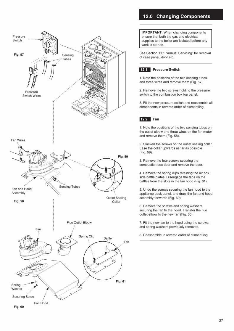
12.1 Pressure Switch
1. Note the positions of the two sensing tubesand three wires and remove them (Fig. 57).
2. Remove the two screws holding the pressureswitch to the combustion box top panel.
3. Fit the new pressure switch and reassemble allcomponents in reverse order of dismantling.
12.2 Fan
1. Note the positions of the two sensing tubes onthe outlet elbow and three wires on the fan motorand remove them (Fig. 58).
2. Slacken the screws on the outlet sealing collar.Ease the collar upwards as far as possible (Fig. 59).
3. Remove the four screws securing thecombustion box door and remove the door.
4. Remove the spring clips retaining the air boxside baffle plates. Disengage the tabs on thebaffles from the slots in the fan hood (Fig. 61).
5. Undo the screws securing the fan hood to theappliance back panel, and draw the fan and hoodassembly forwards (Fig. 60).
6. Remove the screws and spring washerssecuring the fan to the hood. Transfer the flueoutlet elbow to the new fan (Fig. 60).
7. Fit the new fan to the hood using the screwsand spring washers previously removed.
8. Reassemble in reverse order of dismantling. Spring Clip
Flue Outlet Elbow
Fan
Fan Hood
SpringWasher
Securing Screw
BaffleTab
Fan Wires
Fan and HoodAssembly
Sensing Tubes
Outlet SealingCollar
PressureSwitch
SensingTubes
Pressure Switch Wires
Fig. 57
Fig. 58
Fig. 60
Fig. 61
Fig. 59
12.0 Changing Components
28
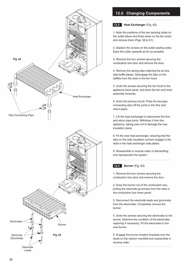
12.3 Heat Exchanger (Fig. 62)
1. Note the positions of the two sensing tubes onthe outlet elbow and three wires on the fan motorand remove them (Figs. 58 to 61).
2. Slacken the screws on the outlet sealing collar.Ease the collar upwards as far as possible.
3. Remove the four screws securing thecombustion box door and remove the door.
4. Remove the spring clips retaining the air boxside baffle plates. Disengage the tabs on thebaffles from the slots in the fan hood.
5. Undo the screws securing the fan hood to theappliance back panel, and draw the fan and hoodassembly forwards.
6. Drain the primary circuit. Prise the two pipeconnecting clips off the joints in the flow andreturn pipes.
7. Lift the heat exchanger to disconnect the flowand return pipe joints. Withdraw it from theappliance, taking care not to damage the rearinsulation piece.
8. Fit the new heat exchanger, ensuring that thetabs on the side insulation carriers engage in theslots in the heat exchanger side plates.
9. Reassemble in reverse order of dismantling,and repressurise the system.
12.4 Burner (Fig. 63)
1. Remove the four screws securing thecombustion box door and remove the door.
2. Draw the burner out of the combustion box,pulling the electrode grommets from the slots inthe combustion box lower panel.
3. Disconnect the electrode leads and grommetsfrom the electrodes. Completely remove theburner.
4. Undo the screws securing the electrodes to theburner. Examine the condition of the electrodes,replacing if necessary. Fit the electrodes to thenew burner.
5. Engage the burner location brackets over thestuds on the injector manifold and reassemble inreverse order.
Burner
ElectrodeGrommets
Electrode Leads
Electrodes
Pipe Connecting Clips
Heat Exchanger
Fig. 62
Fig. 63
12.0 Changing Components
29
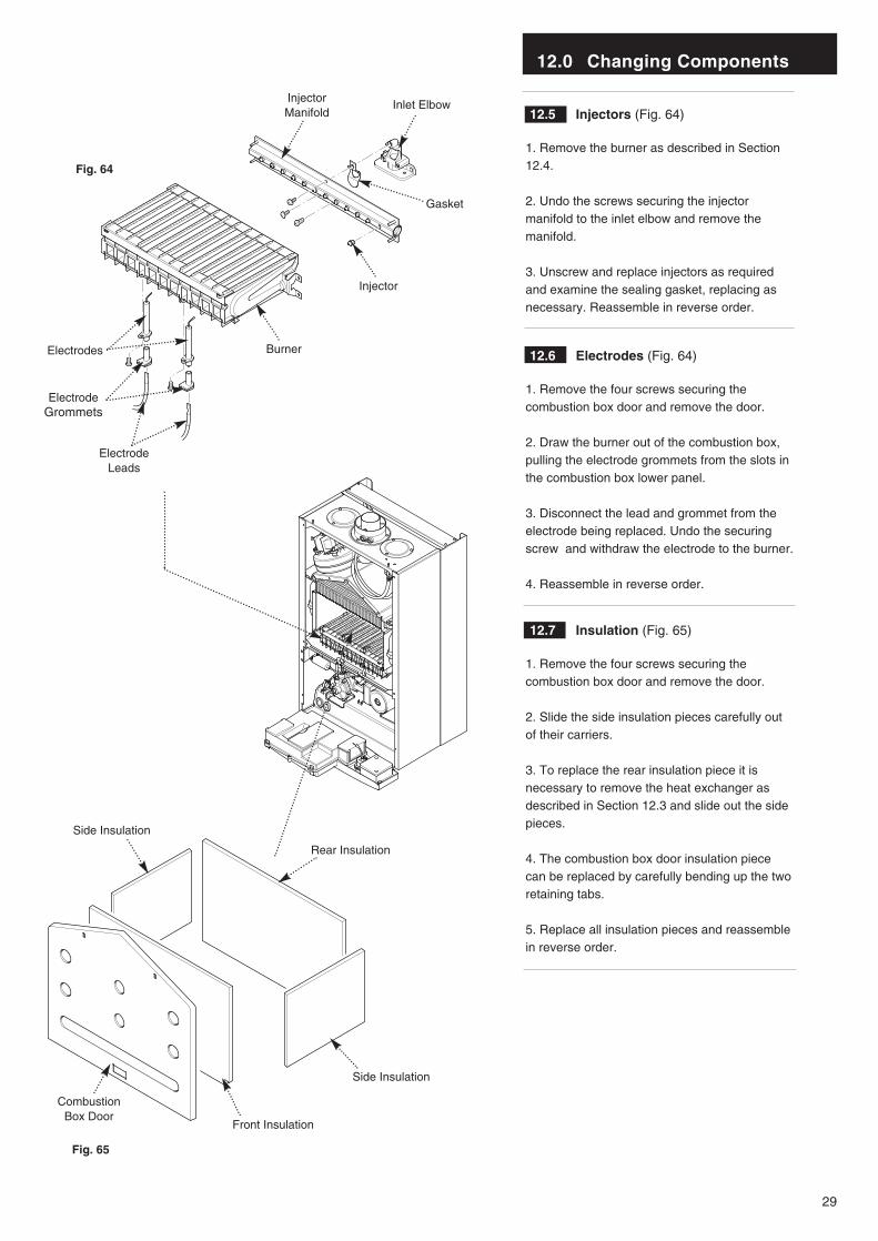
12.5 Injectors (Fig. 64)
1. Remove the burner as described in Section12.4.
2. Undo the screws securing the injectormanifold to the inlet elbow and remove themanifold.
3. Unscrew and replace injectors as requiredand examine the sealing gasket, replacing asnecessary. Reassemble in reverse order.
12.6 Electrodes (Fig. 64)
1. Remove the four screws securing thecombustion box door and remove the door.
2. Draw the burner out of the combustion box,pulling the electrode grommets from the slots inthe combustion box lower panel.
3. Disconnect the lead and grommet from theelectrode being replaced. Undo the securingscrew and withdraw the electrode to the burner.
4. Reassemble in reverse order.
12.7 Insulation (Fig. 65)
1. Remove the four screws securing thecombustion box door and remove the door.
2. Slide the side insulation pieces carefully outof their carriers.
3. To replace the rear insulation piece it isnecessary to remove the heat exchanger asdescribed in Section 12.3 and slide out the sidepieces.
4. The combustion box door insulation piececan be replaced by carefully bending up the tworetaining tabs.
5. Replace all insulation pieces and reassemblein reverse order.
13.8
InjectorManifold
Inlet Elbow
Gasket
Injector
Burner
ElectrodeGrommets
Electrode Leads
Side Insulation
Rear Insulation
Front Insulation
CombustionBox Door
Side Insulation
Electrodes
Fig. 64
Fig. 65
12.0 Changing Components
30
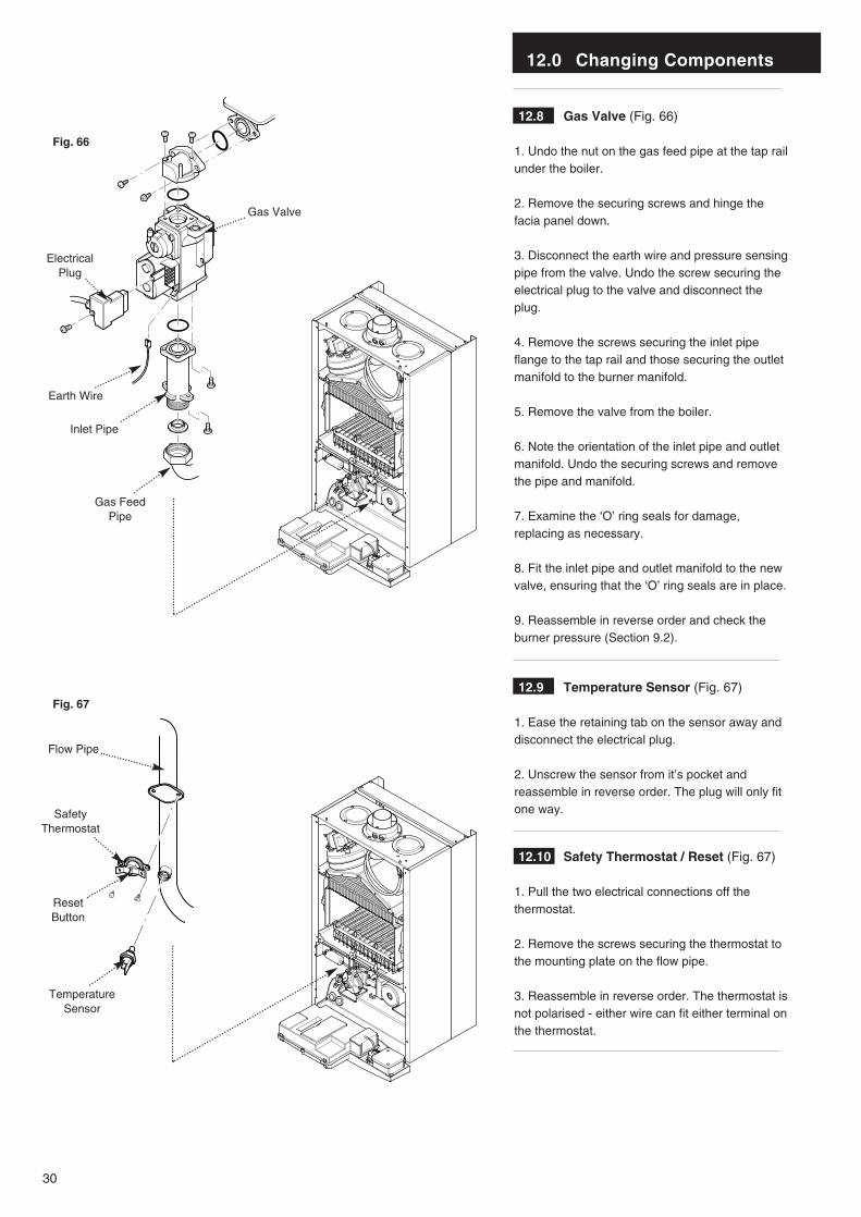
12.8 Gas Valve (Fig. 66)
1. Undo the nut on the gas feed pipe at the tap railunder the boiler.
2. Remove the securing screws and hinge thefacia panel down.
3. Disconnect the earth wire and pressure sensingpipe from the valve. Undo the screw securing theelectrical plug to the valve and disconnect theplug.
4. Remove the screws securing the inlet pipeflange to the tap rail and those securing the outletmanifold to the burner manifold.
5. Remove the valve from the boiler.
6. Note the orientation of the inlet pipe and outletmanifold. Undo the securing screws and removethe pipe and manifold.
7. Examine the ‘O’ ring seals for damage,replacing as necessary.
8. Fit the inlet pipe and outlet manifold to the newvalve, ensuring that the ‘O’ ring seals are in place.
9. Reassemble in reverse order and check theburner pressure (Section 9.2).
12.9 Temperature Sensor (Fig. 67)
1. Ease the retaining tab on the sensor away anddisconnect the electrical plug.
2. Unscrew the sensor from it’s pocket andreassemble in reverse order. The plug will only fitone way.
12.10 Safety Thermostat / Reset (Fig. 67)
1. Pull the two electrical connections off thethermostat.
2. Remove the screws securing the thermostat tothe mounting plate on the flow pipe.
3. Reassemble in reverse order. The thermostat isnot polarised - either wire can fit either terminal onthe thermostat.
Gas Valve
Inlet Pipe
Gas FeedPipe
Earth Wire
ElectricalPlug
TemperatureSensor
SafetyThermostat
Flow Pipe
ResetButton
Fig. 66
Fig. 67
12.0 Changing Components
31
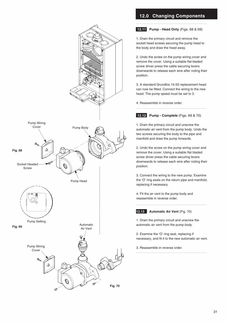
12.11 Pump - Head Only (Figs. 68 & 69)
1. Drain the primary circuit and remove thesocket head screws securing the pump head tothe body and draw the head away.
2. Undo the screw on the pump wiring cover andremove the cover. Using a suitable flat bladedscrew driver press the cable securing leversdownwards to release each wire after noting theirposition.
3. A standard Grundfos 15-50 replacement headcan now be fitted. Connect the wiring to the newhead. The pump speed must be set to 3.
4. Reassemble in reverse order.
12.12 Pump - Complete (Figs. 69 & 70)
1. Drain the primary circuit and unscrew theautomatic air vent from the pump body. Undo thetwo screws securing the body to the pipe andmanifold and draw the pump forwards.
2. Undo the screw on the pump wiring cover andremove the cover. Using a suitable flat bladedscrew driver press the cable securing leversdownwards to release each wire after noting theirposition.
3. Connect the wiring to the new pump. Examinethe ‘O’ ring seals on the return pipe and manifold,replacing if necessary.
4. Fit the air vent to the pump body andreassemble in reverse order.
12.13 Automatic Air Vent (Fig. 70)
1. Drain the primary circuit and unscrew theautomatic air vent from the pump body.
2. Examine the ‘O’ ring seal, replacing ifnecessary, and fit it to the new automatic air vent.
3. Reassemble in reverse order.
Pump Setting
Pump WiringCover
Socket HeadedScrew
Pump Head
Pump Body
Pump WiringCover
AutomaticAir Vent
Fig. 68
Fig. 69
Fig. 70
12.0 Changing Components
32
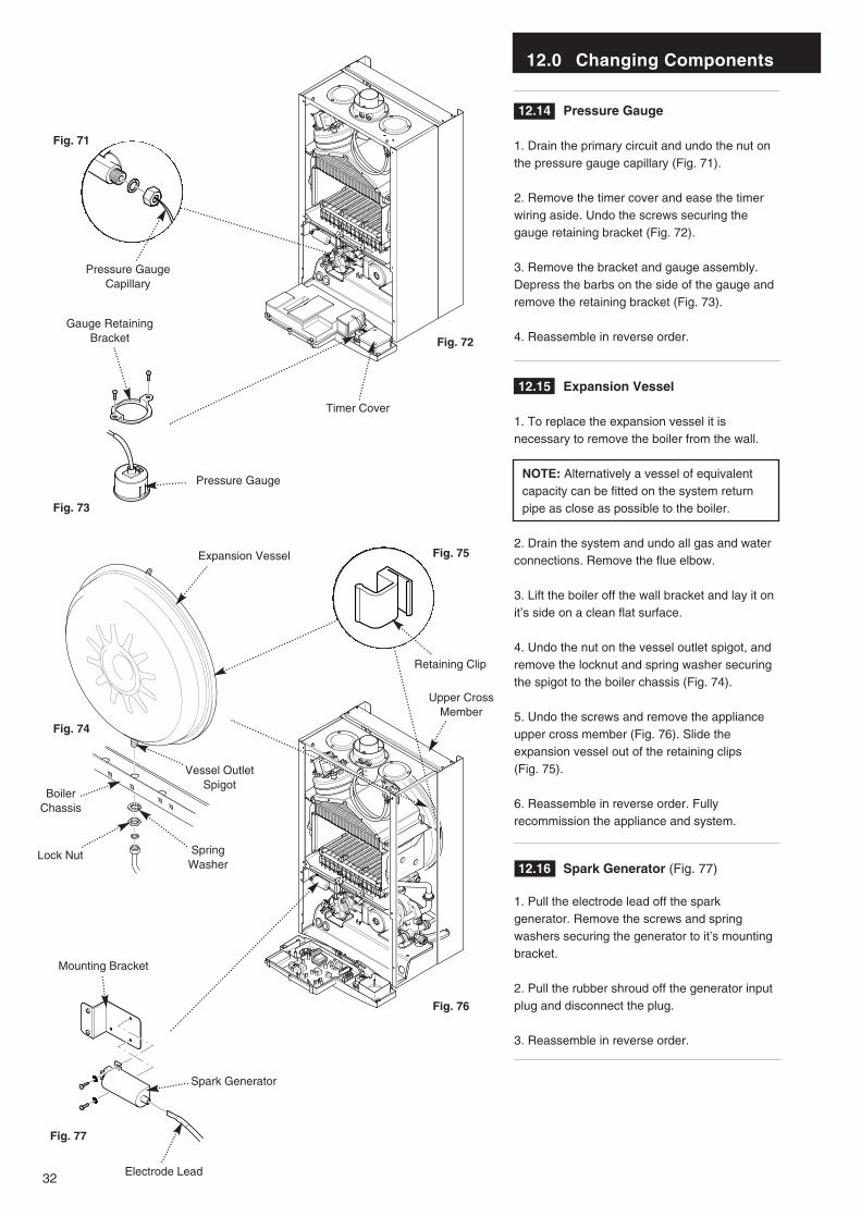
12.14 Pressure Gauge
1. Drain the primary circuit and undo the nut onthe pressure gauge capillary (Fig. 71).
2. Remove the timer cover and ease the timerwiring aside. Undo the screws securing thegauge retaining bracket (Fig. 72).
3. Remove the bracket and gauge assembly.Depress the barbs on the side of the gauge andremove the retaining bracket (Fig. 73).
4. Reassemble in reverse order.
12.15 Expansion Vessel
1. To replace the expansion vessel it isnecessary to remove the boiler from the wall.
NOTE: Alternatively a vessel of equivalentcapacity can be fitted on the system returnpipe as close as possible to the boiler.
2. Drain the system and undo all gas and waterconnections. Remove the flue elbow.
3. Lift the boiler off the wall bracket and lay it onit’s side on a clean flat surface.
4. Undo the nut on the vessel outlet spigot, andremove the locknut and spring washer securingthe spigot to the boiler chassis (Fig. 74).
5. Undo the screws and remove the applianceupper cross member (Fig. 76). Slide theexpansion vessel out of the retaining clips (Fig. 75).
6. Reassemble in reverse order. Fullyrecommission the appliance and system.
12.16 Spark Generator (Fig. 77)
1. Pull the electrode lead off the sparkgenerator. Remove the screws and springwashers securing the generator to it’s mountingbracket.
2. Pull the rubber shroud off the generator inputplug and disconnect the plug.
3. Reassemble in reverse order.
Pressure Gauge
Timer Cover
Pressure GaugeCapillary
Gauge RetainingBracket
Expansion Vessel
Retaining Clip
Vessel OutletSpigot
BoilerChassis
Lock Nut SpringWasher
Electrode Lead
Spark Generator
Mounting Bracket
Fig. 72
Fig. 71
Fig. 73
Fig. 74
Fig. 75
Fig. 76
Fig. 77
Upper CrossMember
12.0 Changing Components
33
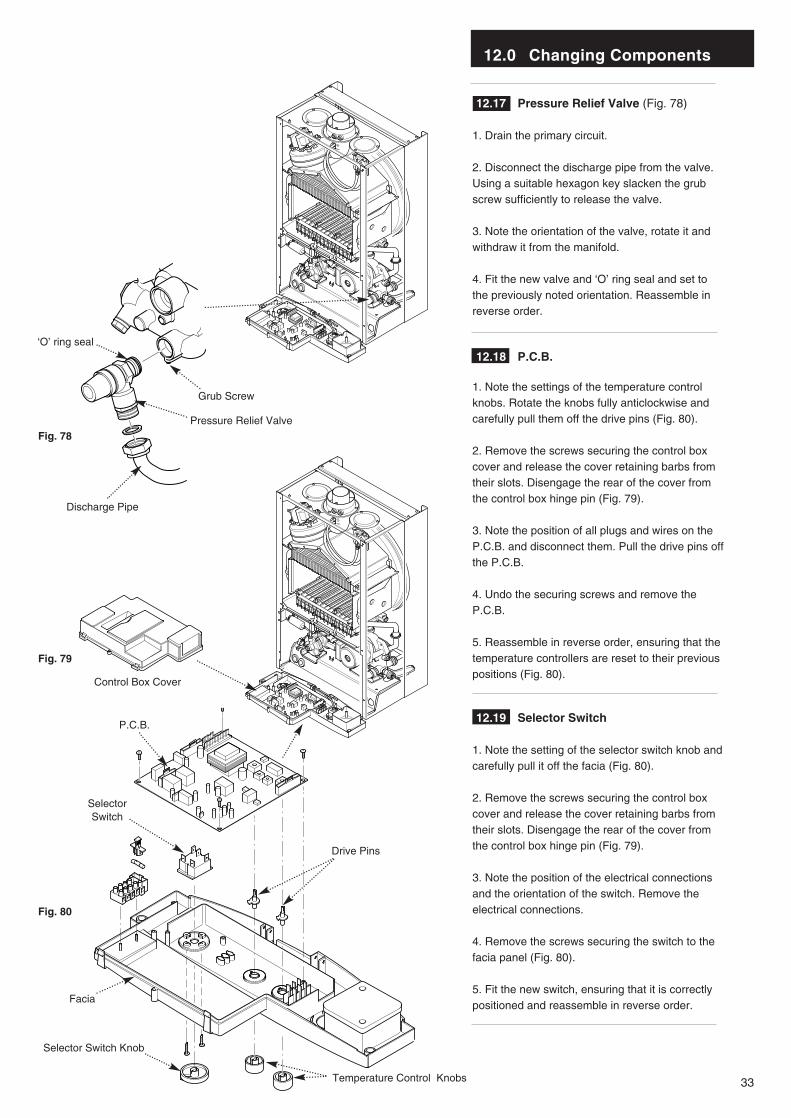
12.17 Pressure Relief Valve (Fig. 78)
1. Drain the primary circuit.
2. Disconnect the discharge pipe from the valve.Using a suitable hexagon key slacken the grubscrew sufficiently to release the valve.
3. Note the orientation of the valve, rotate it andwithdraw it from the manifold.
4. Fit the new valve and ‘O’ ring seal and set tothe previously noted orientation. Reassemble inreverse order.
12.18 P.C.B.
1. Note the settings of the temperature controlknobs. Rotate the knobs fully anticlockwise andcarefully pull them off the drive pins (Fig. 80).
2. Remove the screws securing the control boxcover and release the cover retaining barbs fromtheir slots. Disengage the rear of the cover fromthe control box hinge pin (Fig. 79).
3. Note the position of all plugs and wires on theP.C.B. and disconnect them. Pull the drive pins offthe P.C.B.
4. Undo the securing screws and remove theP.C.B.
5. Reassemble in reverse order, ensuring that thetemperature controllers are reset to their previouspositions (Fig. 80).
12.19 Selector Switch
1. Note the setting of the selector switch knob andcarefully pull it off the facia (Fig. 80).
2. Remove the screws securing the control boxcover and release the cover retaining barbs fromtheir slots. Disengage the rear of the cover fromthe control box hinge pin (Fig. 79).
3. Note the position of the electrical connectionsand the orientation of the switch. Remove theelectrical connections.
4. Remove the screws securing the switch to thefacia panel (Fig. 80).
5. Fit the new switch, ensuring that it is correctlypositioned and reassemble in reverse order.
Pressure Relief Valve
Grub Screw
‘O’ ring seal
Discharge Pipe
Control Box Cover
P.C.B.
SelectorSwitch
Facia
Selector Switch Knob
Temperature Control Knobs
Fig. 78
Fig. 79
Fig. 80
Drive Pins
12.0 Changing Components
34
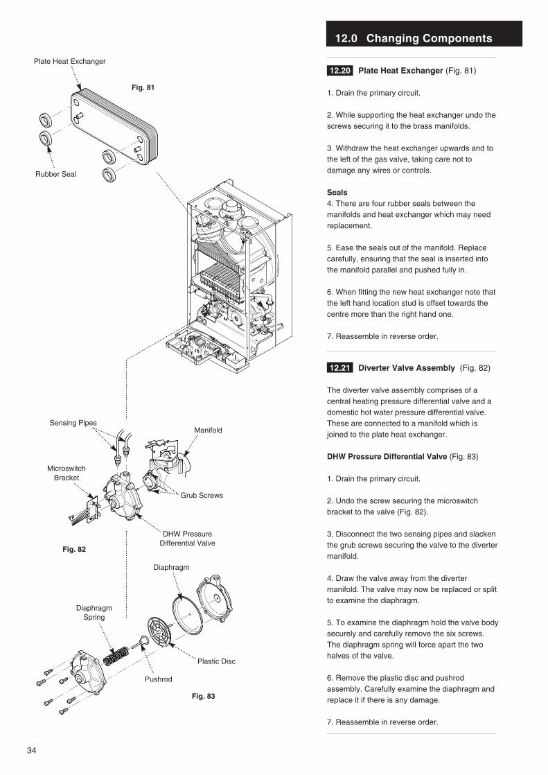
12.20 Plate Heat Exchanger (Fig. 81)
1. Drain the primary circuit.
2. While supporting the heat exchanger undo thescrews securing it to the brass manifolds.
3. Withdraw the heat exchanger upwards and tothe left of the gas valve, taking care not todamage any wires or controls.
Seals4. There are four rubber seals between themanifolds and heat exchanger which may needreplacement.
5. Ease the seals out of the manifold. Replacecarefully, ensuring that the seal is inserted intothe manifold parallel and pushed fully in.
6. When fitting the new heat exchanger note thatthe left hand location stud is offset towards thecentre more than the right hand one.
7. Reassemble in reverse order.
12.21 Diverter Valve Assembly (Fig. 82)
The diverter valve assembly comprises of acentral heating pressure differential valve and adomestic hot water pressure differential valve.These are connected to a manifold which isjoined to the plate heat exchanger.
DHW Pressure Differential Valve (Fig. 83)
1. Drain the primary circuit.
2. Undo the screw securing the microswitchbracket to the valve (Fig. 82).
3. Disconnect the two sensing pipes and slackenthe grub screws securing the valve to the divertermanifold.
4. Draw the valve away from the divertermanifold. The valve may now be replaced or splitto examine the diaphragm.
5. To examine the diaphragm hold the valve bodysecurely and carefully remove the six screws.The diaphragm spring will force apart the twohalves of the valve.
6. Remove the plastic disc and pushrodassembly. Carefully examine the diaphragm andreplace it if there is any damage.
7. Reassemble in reverse order.
Plate Heat Exchanger
Rubber Seal
DHW Pressure Differential Valve
MicroswitchBracket
Grub Screws
ManifoldSensing Pipes
Plastic Disc
Pushrod
DiaphragmSpring
Diaphragm
Fig. 81
Fig. 82
Fig. 83
12.0 Changing Components
35
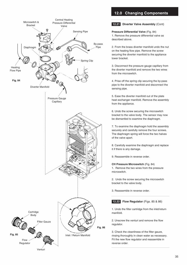
12.21 Diverter Valve Assembly (Cont)
Pressure Differential Valve (Fig. 84)1. Remove the pressure differential valve asdescribed above.
2. From the brass diverter manifold undo the nuton the heating flow pipe. Remove the screwsecuring the diverter manifold to the appliancelower bracket.
3. Disconnect the pressure gauge capillary fromthe diverter manifold and remove the two wiresfrom the microswitch.
4. Prise off the spring clip securing the by-passpipe to the diverter manifold and disconnect thesensing pipe.
5. Ease the diverter manifold out of the plateheat exchanger manifold. Remove the assemblyfrom the appliance.
6. Undo the screw securing the microswitchbracket to the valve body. The sensor may nowbe dismantled to examine the diaphragm.
7. To examine the diaphragm hold the assemblysecurely and carefully remove the four screws.The diaphragm spring will force the two halvesof the valve apart.
8. Carefully examine the diaphragm and replaceit if there is any damage.
9. Reassemble in reverse order.
CH Pressure Microswitch (Fig. 84)1. Remove the two wires from the pressuremicroswitch.
2. Undo the screw securing the microswitchbracket to the valve body.
3. Reassemble in reverse order.
12.22 Flow Regulator (Figs. 85 & 86)
1. Undo the filter cartridge from the inlet/returnmanifold.
2. Unscrew the venturi and remove the flowregulator.
3. Check the cleanliness of the filter gauze,rinsing thoroughly in clean water as necessary.Fit the new flow regulator and reassemble inreverse order.
Pressure GaugeCapillary
HeatingFlow Pipe
Spring Clip
By-passPipe
Sensing Pipe
Diaphragm
Diverter Manifold
Microswitch &Bracket
Fig. 84
Inlet / Return Manifold
CartridgeBody
Filter Gauze
FlowRegulator
Venturi
Fig. 85
Fig. 86
Central HeatingPressure Differential
Valve
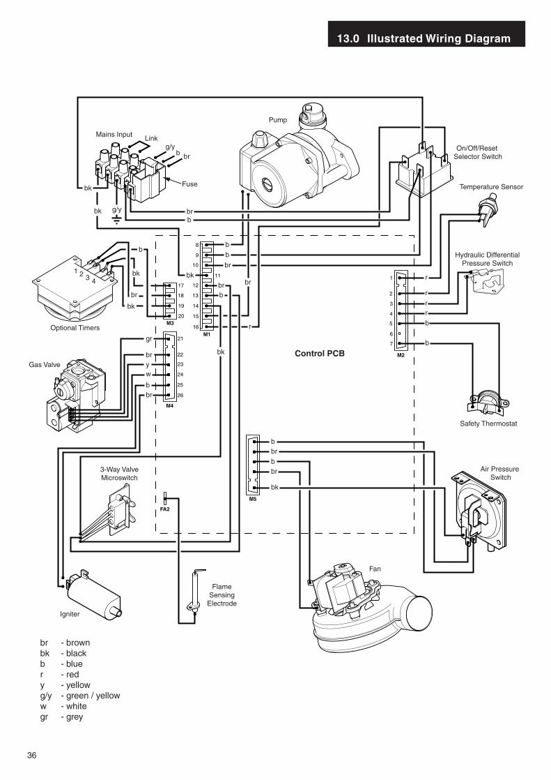
13.0 Illustrated Wiring Diagram
36
Optional Timers
Pump
Gas Valve
Air Pressure Switch
Safety Thermostat
Hydraulic DifferentialPressure Switch
Temperature Sensor
On/Off/Reset Selector Switch
Fan
Control PCB
FlameSensing
Electrode
Igniter
3-Way ValveMicroswitch
M2
M5
M4
M1
M3
FA2
15
16
14
13
12
20
19
18
17
11
10
26
25
24
23
22
21
9
7
6
5
4
3
2
1
8
br - brownbk - blackb - bluer - redy - yellowg/y - green / yelloww - whitegr - grey
Mains Input
Fuse
Link
g/y
g/yb br
b
bb
b
br
br
br br
r
bk
gr
br
br
bk
brbbr
r
r
rr
b
b
b
yw
b
1
bk
bk
bk
b
bk
bk
br
2 3 4
14.0 Fault Finding
37
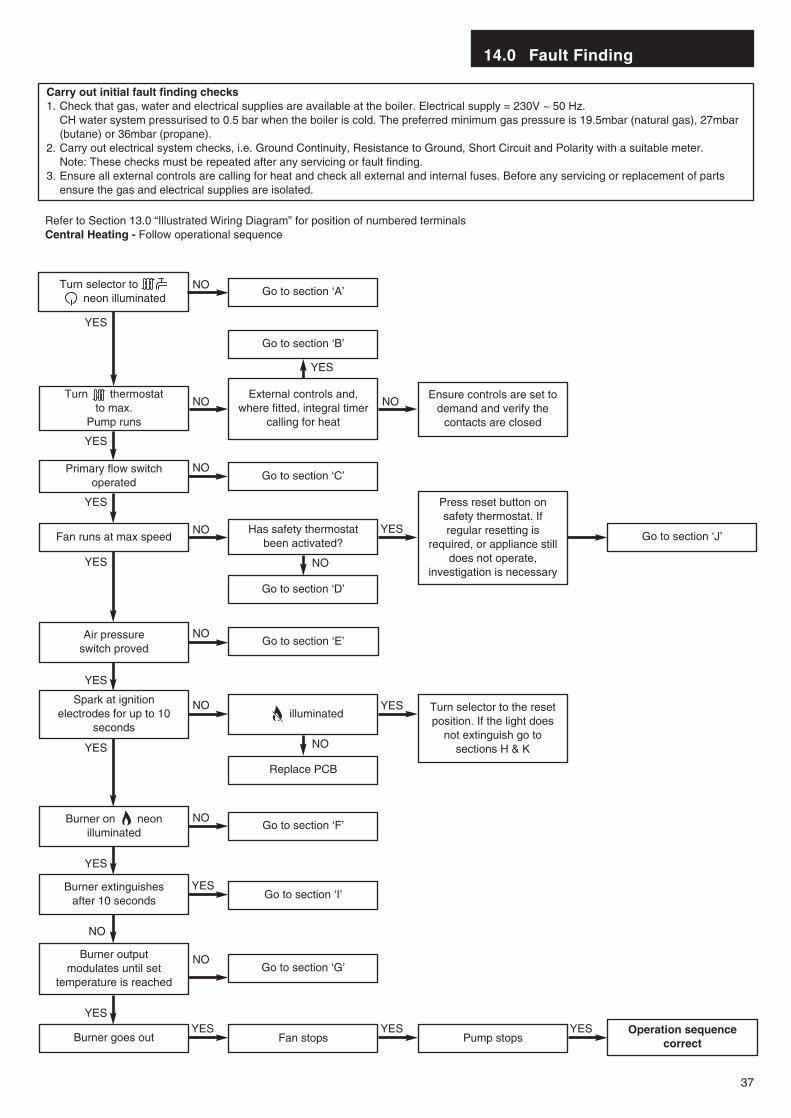
Carry out initial fault finding checks1. Check that gas, water and electrical supplies are available at the boiler. Electrical supply = 230V ~ 50 Hz.
CH water system pressurised to 0.5 bar when the boiler is cold. The preferred minimum gas pressure is 19.5mbar (natural gas), 27mbar (butane) or 36mbar (propane).
2. Carry out electrical system checks, i.e. Ground Continuity, Resistance to Ground, Short Circuit and Polarity with a suitable meter. Note: These checks must be repeated after any servicing or fault finding.
3. Ensure all external controls are calling for heat and check all external and internal fuses. Before any servicing or replacement of parts ensure the gas and electrical supplies are isolated.
Refer to Section 13.0 “Illustrated Wiring Diagram” for position of numbered terminalsCentral Heating - Follow operational sequence
Turn selector to neon illuminated
Primary flow switchoperated
Fan runs at max speed
Burner goes out
Turn thermostat to max.
Pump runs
Air pressure switch proved
illuminated
Burner on neonilluminated
Burner output modulates until set
temperature is reached
Spark at ignitionelectrodes for up to 10
seconds
Go to section ‘A’
Go to section ‘B’
Go to section ‘C’
Go to section ‘J’
Go to section ‘D’
Go to section ‘E’
Replace PCB
Turn selector to the resetposition. If the light does
not extinguish go tosections H & K
Go to section ‘F’
Go to section ‘I’
Go to section ‘G’
Fan stops Pump stopsOperation sequence
correct
Has safety thermostatbeen activated?
Press reset button onsafety thermostat. Ifregular resetting is
required, or appliance stilldoes not operate,
investigation is necessary
External controls and,where fitted, integral timer
calling for heat
Ensure controls are set todemand and verify the
contacts are closed
Burner extinguishes after 10 seconds
YES
YES
YES
YES
YES
YES
YES
YES
YES
YES
NO
YESYES YES YES
NO
NO NO
NO
NO
NO
NO
NO
NO
NO
YES
NO
14.0 Fault Finding
38
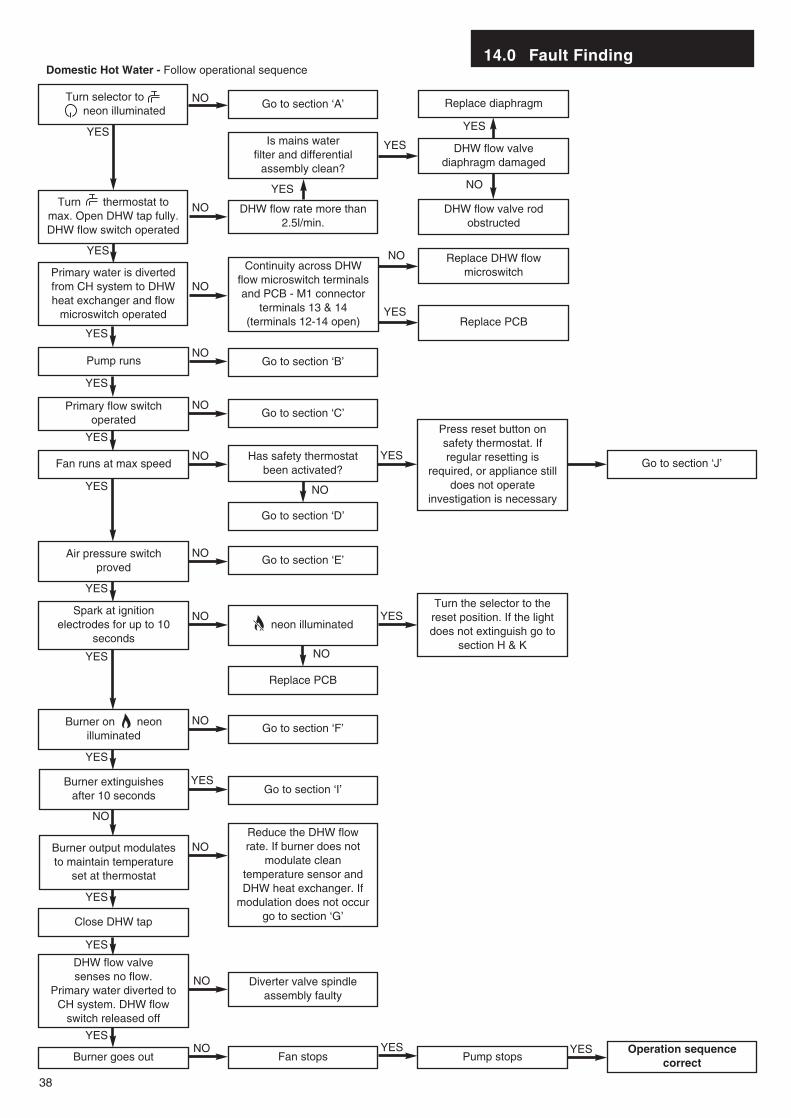
Domestic Hot Water - Follow operational sequence
Turn selector to neon illuminated
Primary flow switchoperated
Fan runs at max speed
Pump runs
Turn thermostat tomax. Open DHW tap fully.DHW flow switch operated
Primary water is divertedfrom CH system to DHWheat exchanger and flow
microswitch operated
Continuity across DHWflow microswitch terminalsand PCB - M1 connector
terminals 13 & 14(terminals 12-14 open)
Air pressure switchproved
neon illuminated
Burner on neonilluminated
Spark at ignitionelectrodes for up to 10
seconds
Go to section ‘A’
Go to section ‘B’
Go to section ‘C’
Go to section ‘J’
Go to section ‘D’
Replace PCB
Turn the selector to thereset position. If the lightdoes not extinguish go to
section H & K
Go to section ‘F’
Go to section ‘I’
DHW flow valve senses no flow.
Primary water diverted toCH system. DHW flow
switch released off
Close DHW tap
Burner goes out
Diverter valve spindleassembly faulty
Pump stopsOperation sequence
correct
Has safety thermostatbeen activated?
Press reset button onsafety thermostat. Ifregular resetting is
required, or appliance stilldoes not operate
investigation is necessary
Go to section ‘E’
Burner extinguishes after 10 seconds
YES
YES
YES
YES
YES
YES
YES
YES
YES
YES
YES
YES
YES
YES
YES
YES
NO
Fan stopsNO YES YES
YES
YES
NO
NO
DHW flow rate more than2.5l/min.
Is mains water filter and differential
assembly clean?
DHW flow valvediaphragm damaged
DHW flow valve rodobstructed
Replace DHW flowmicroswitch
Replace PCB
Replace diaphragm
NO
NO
NO
YES
NO
NO
NO
NO
NO
NO
NO
NOReduce the DHW flowrate. If burner does not
modulate cleantemperature sensor andDHW heat exchanger. If
modulation does not occurgo to section ‘G’
Burner output modulatesto maintain temperature
set at thermostat
NO
NO
14.0 Fault Finding
39
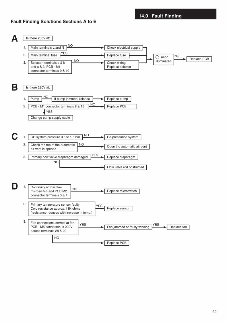
Fault Finding Solutions Sections A to E
Is there 230V at:
Is there 230V at:
Main terminals L and N Check electrical supply1. NO
Main terminal fuse Replace fuseReplace PCBneon
illuminated
2. YES
Selector terminals a & band a & 3. PCB - M1connector terminals 9 & 10
Check wiringReplace selector
3. NO
NO
A
Pump Replace pump1. NO
PCB - M1 connector terminals 8 & 15 Replace PCB2. NO
Change pump supply cable
YES
B
CH system pressure 0.5 to 1.5 bar Re-pressurise system1. NO
Primary flow valve diaphragm damaged Replace diaphragm
Flow valve rod obstructed
3. YES
Check the tap of the automaticair vent is opened
Open the automatic air vent2. NO
NO
C
YES
Continuity across flowmicroswitch and PCB M2connector terminals 3 & 4
Replace microswitch1.
NO
NO
Primary temperature sensor faulty. Cold resistance approx. 11K ohms (resistance reduces with increase in temp.)
Replace sensor2.
YESFan connections correct at fan.PCB - M5 connector, is 230Vacross terminals 28 & 29
Fan jammed or faulty winding
Replace PCB
Replace fanYES
3.
D
If pump jammed, release
14.0 Fault Finding
40
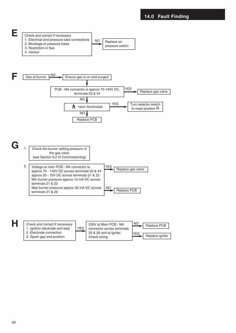
Check and correct if necessary1. Electrical and pressure tube connections2. Blockage of pressure tubes3. Restriction in flue4. Venturi
NO
EReplace airpressure switch
Gas at burner Ensure gas is on and purged
Replace PCB
Replace gas valve
neon illuminated
PCB - M4 connector is approx 70-140V DC,terminals 23 & 24
YES
Turn selector switchto reset position R
YES
NO
NO
NO
F
Replace PCB
G
Check and correct if necessary1. Ignition electrode and lead2. Electrode connection3. Spark gap and position
230V at Main PCB - M4connector across terminals 25 & 26 and at igniter.Check wiring
YESNO
Replace igniterYES
H
YES
Check the burner setting pressure ofthe gas valve
(see Section 9.2 of Commissioning)
1.
Voltage at main PCB - M4 connector is:approx 70 - 140V DC across terminals 23 & 24approx 20 - 70V DC across terminals 21 & 22Min burner pressure approx 14 mA DC acrossterminals 21 & 22Max burner pressure approx 35 mA DC acrossterminals 21 & 22
Replace gas valve
NOReplace PCB
2.
14.0 Fault Finding
41
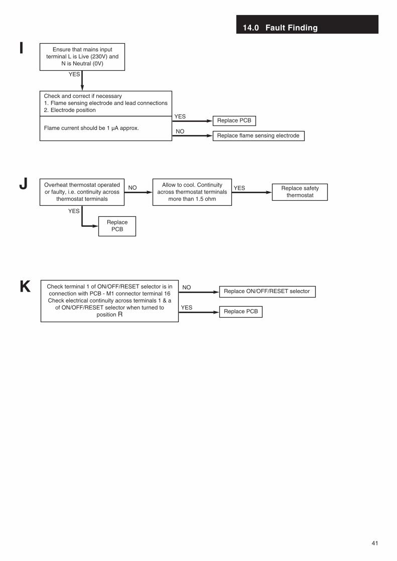
Check and correct if necessary1. Flame sensing electrode and lead connections2. Electrode position
Flame current should be 1 µA approx.Replace PCB
ReplacePCB
YES
YES
Replace flame sensing electrodeNO
YES
Ensure that mains inputterminal L is Live (230V) and
N is Neutral (0V)
I
Check terminal 1 of ON/OFF/RESET selector is inconnection with PCB - M1 connector terminal 16Check electrical continuity across terminals 1 & a
of ON/OFF/RESET selector when turned toposition R
Replace ON/OFF/RESET selectorNO
Replace PCBYES
K
Replace safetythermostat
YESNOOverheat thermostat operatedor faulty, i.e. continuity across
thermostat terminals
Allow to cool. Continuityacross thermostat terminals
more than 1.5 ohm
J
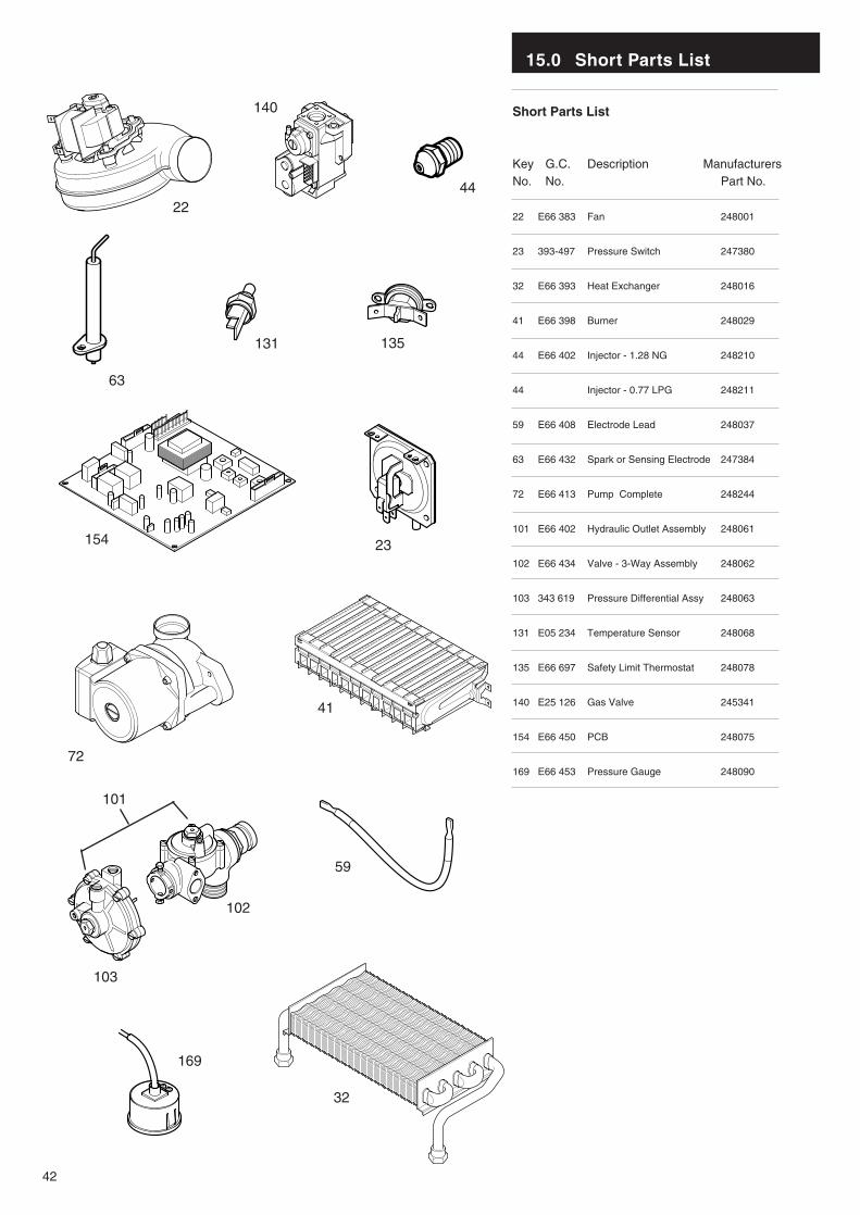
15.0 Short Parts List
42
Short Parts List
Key G.C. Description ManufacturersNo. No. Part No.
22 E66 383 Fan 248001
23 393-497 Pressure Switch 247380
32 E66 393 Heat Exchanger 248016
41 E66 398 Burner 248029
44 E66 402 Injector - 1.28 NG 248210
44 Injector - 0.77 LPG 248211
59 E66 408 Electrode Lead 248037
63 E66 432 Spark or Sensing Electrode 247384
72 E66 413 Pump Complete 248244
101 E66 402 Hydraulic Outlet Assembly 248061
102 E66 434 Valve - 3-Way Assembly 248062
103 343 619 Pressure Differential Assy 248063
131 E05 234 Temperature Sensor 248068
135 E66 697 Safety Limit Thermostat 248078
140 E25 126 Gas Valve 245341
154 E66 450 PCB 248075
169 E66 453 Pressure Gauge 248090
22
140
44
63
154
72
135
59
41
101
102
103
32
169
131
23
43
Baxi UK Limited manufacture a comprehensive rangeof products for the domestic heating market.
Gas Central Heating Boilers(Wall, Floor and Fireside models).
Independent Gas Fires.
Renewal Firefronts.
Gas Wall Heaters.
Solid Fuel Fires.
If you require information on any of these products,please write, telephone or fax to the Sales Department.
Baxi UK LimitedBrownedge Road
Bamber Bridge PrestonLancashirePR5 6SN
www.baxi.com
After Sales Service08706 096 096
Technical Enquiries08706 049 049
Comp No 247936 - Iss 6 - 6/02
921.648.3