Embed Size (px)
Citation preview
Installation and Servicing Instructions
GREENSTAR HE combiWall mounted condensing boiler for central heating and mainsfed domestic hot water
6 720 610 577-00.10
ZWB 7-27 HE combi GC-Number: 47 311 55
SW
6 72
0 61
0 57
6 G
B (0
2.05
) O
Contents
Contents
Safety precautions 3
Symbols 3
1 Details of the appliance 41.1 EC Declaration of Conformity 41.2 Standard package 41.3 Description of appliance 41.4 Accessories 51.5 Casing dimensions 51.6 Layout of appliance 61.7 Function 71.8 Electrical wiring diagram 81.9 Technical data 9
2 Installation regulations 11
3 Installation 113.1 Important remarks 113.2 Domestic hot water 123.3 Sealed systems 123.4 Siting the appliance 133.5 Wall mounting frame assembly 143.6 Pre-piping the system 143.7 Fitting the appliance 153.8 Checking the connections 163.9 Flue Systems 163.9.1 Siting the Flue Terminal 173.9.2 Installation of the flue 183.9.3 Flue duct preparation and assembly 20
4 Electrical connections 214.1 Connecting the appliance 214.2 Mains Voltage external controls connections 22
5 Commissioning 235.1 Commissioning 235.2 Switching the appliance on/off 245.3 Switching on the central heating 245.4 System controls 245.5 Setting the domestic hot water
temperature and flow rate 245.5.1 Domestic hot water temperature 245.5.2 Hot water flow rate 255.6 Summer mode (hot water only) 255.7 Frost protection 255.8 Pump anti-seize function 255.9 Fault Condition 25
6 Individual settings 266.1 Mechanical settings 266.1.1 Checking the size of the expansion vessel 266.1.2 Setting the central heating flow temperature 266.1.3 Changing the heating pump characteristic 266.2 Settings on the Bosch Heatronic 276.2.1 Operating the Bosch Heatronic 276.2.2 Selecting the pump control mode for central
heating mode (Service Function 2.2) 276.2.3 Setting the anti-cycle time
(Service Function 2.4) 276.2.4 Setting the maxim CH flow temperature
(Service Function 2.5) 286.2.5 Setting the switching difference
(Service Function 2.6) 286.2.6 Setting the heating output
(Service Function 5.0) 286.2.7 Constant hot water cycle time
(Service Function 6.8) 286.3 Setting the gas/air ratio 28
7 Converting the appliance to different gas types 29
7.1 Setting the gas/air ratio 297.2 Testing combustion air/flue gas at set
heat output 317.2.1 Testing the O2 or CO2 level in the
combustion air 317.2.2 Testing CO and CO2 31
8 Maintenance 328.1 Pre-Service Check List 338.2 Description of servicing operations 348.3 Replacement of Parts 388.3.1 PCB control board and transformer 388.3.2 Fan Assembly 398.3.3 Pump 398.3.4 3-way diverter valve 408.3.5 3-way diverter valve motor 408.3.6 Sensors 408.3.7 Gas Valve 418.3.8 Domestic Hot Water Heat Exchanger 418.3.9 Electrode assembly 418.3.10Pressure gauge 418.3.11Expansion vessel 418.3.12Pressure Relief Valve 418.3.13Burner 418.3.14Flow switch 428.3.15Primary Heat Exchanger 42
9 Appendix 439.1 Fault Codes 439.2 Short parts list 449.3 Heating/hot water output settings (N.G.) 459.4 Heating/hot water output settings (L.P.G) 459.5 Operational Flow diagrams 469.5.1 Domestic hot water function 469.5.2 Central heating function 47
6 720 610 576 GB (02.05)2
Safety precautions
Safety precautions
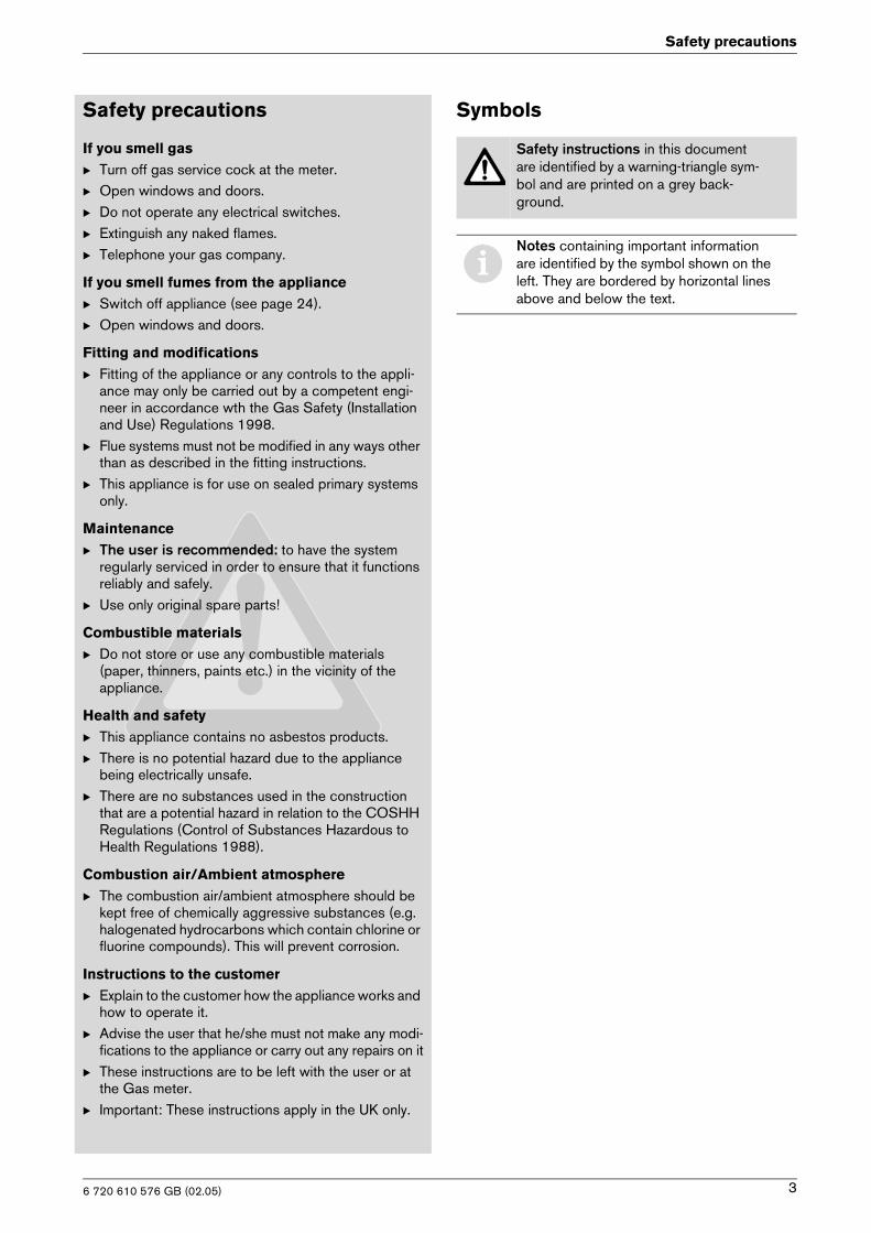
If you smell gasB Turn off gas service cock at the meter.B Open windows and doors.B Do not operate any electrical switches.B Extinguish any naked flames.B Telephone your gas company.
If you smell fumes from the applianceB Switch off appliance (see page 24).B Open windows and doors.
Fitting and modificationsB Fitting of the appliance or any controls to the appli-
ance may only be carried out by a competent engi-neer in accordance wth the Gas Safety (Installation and Use) Regulations 1998.
B Flue systems must not be modified in any ways other than as described in the fitting instructions.
B This appliance is for use on sealed primary systems only.
MaintenanceB The user is recommended: to have the system
regularly serviced in order to ensure that it functions reliably and safely.
B Use only original spare parts!
Combustible materialsB Do not store or use any combustible materials
(paper, thinners, paints etc.) in the vicinity of the appliance.
Health and safetyB This appliance contains no asbestos products.B There is no potential hazard due to the appliance
being electrically unsafe.B There are no substances used in the construction
that are a potential hazard in relation to the COSHH Regulations (Control of Substances Hazardous to Health Regulations 1988).
Combustion air/Ambient atmosphereB The combustion air/ambient atmosphere should be
kept free of chemically aggressive substances (e.g. halogenated hydrocarbons which contain chlorine or fluorine compounds). This will prevent corrosion.
Instructions to the customerB Explain to the customer how the appliance works and
how to operate it.B Advise the user that he/she must not make any modi-
fications to the appliance or carry out any repairs on itB These instructions are to be left with the user or at
the Gas meter.B Important: These instructions apply in the UK only.
Symbols
Safety instructions in this document are identified by a warning-triangle sym-bol and are printed on a grey back-ground.
iNotes containing important information are identified by the symbol shown on the left. They are bordered by horizontal lines above and below the text.
6 720 610 576 GB (02.05) 3
Details of the appliance
1 Details of the appliance
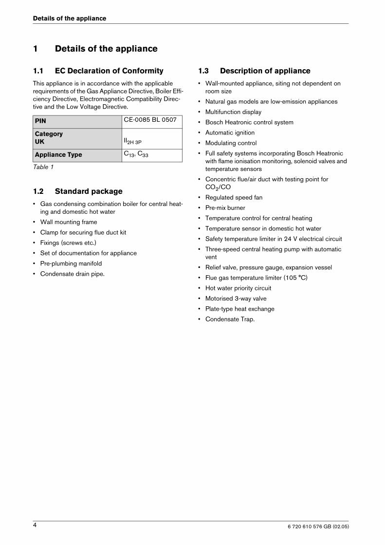
1.1 EC Declaration of Conformity
This appliance is in accordance with the applicable requirements of the Gas Appliance Directive, Boiler Effi-ciency Directive, Electromagnetic Compatibility Direc-tive and the Low Voltage Directive.
1.2 Standard package
• Gas condensing combination boiler for central heat-ing and domestic hot water
• Wall mounting frame
• Clamp for securing flue duct kit
• Fixings (screws etc.)
• Set of documentation for appliance
• Pre-plumbing manifold
• Condensate drain pipe.
1.3 Description of appliance
• Wall-mounted appliance, siting not dependent on room size
• Natural gas models are low-emission appliances
• Multifunction display
• Bosch Heatronic control system
• Automatic ignition
• Modulating control
• Full safety systems incorporating Bosch Heatronic with flame ionisation monitoring, solenoid valves and temperature sensors
• Concentric flue/air duct with testing point forCO2/CO
• Regulated speed fan
• Pre-mix burner
• Temperature control for central heating
• Temperature sensor in domestic hot water
• Safety temperature limiter in 24 V electrical circuit
• Three-speed central heating pump with automatic vent
• Relief valve, pressure gauge, expansion vessel
• Flue gas temperature limiter (105 °C)
• Hot water priority circuit
• Motorised 3-way valve
• Plate-type heat exchange
• Condensate Trap.
PIN CE-0085 BL 0507
CategoryUK II2H 3P
Appliance Type C13, C33
Table 1
6 720 610 576 GB (02.05)4
Details of the appliance
1.4 Accessories
• Standard horizontal flue kit at 100 mm outside diameter for flues upto 4 m in length.
• Flue duct kits for horizontal (125 mm outside diameter) for flue lengths upto 13 m and vertical fluesystems for flue lengths uto 15 m. Fitting instructionsare sent with these kits.
• Heating programmer
• Timer
• Security kit.
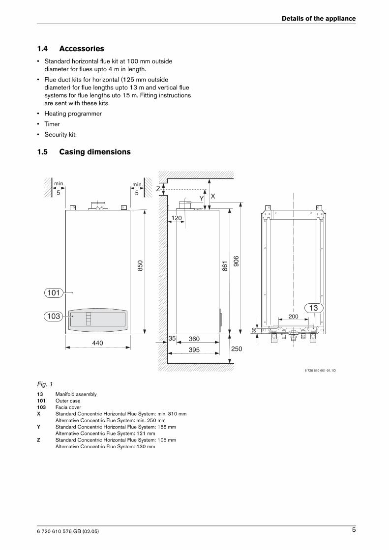
1.5 Casing dimensions
Fig. 113 Manifold assembly 101 Outer case103 Facia coverX Standard Concentric Horizontal Flue System: min. 310 mm
Alternative Concentric Flue System: min. 250 mmY Standard Concentric Horizontal Flue System: 158 mm
Alternative Concentric Flue System: 121 mmZ Standard Concentric Horizontal Flue System: 105 mm
Alternative Concentric Flue System: 130 mm
min.
5min.
5
850
440395 250
360
861 90
6
200
30
6 720 610 601-01.1O
101
103
35
X
13
Y
120
Z
6 720 610 576 GB (02.05) 5
Details of the appliance
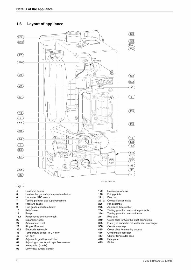
1.6 Layout of appliance
Fig. 24 Heatronic control6 Heat exchanger safety temperature limiter6.1 Hot water NTC sensor7 Testing point for gas supply pressure8.1 Pressure gauge9 Flue gas temperature limiter15 Relief valve18 Pump18.1 Pump speed selector switch20 Expansion vessel27 Automatic air vent29 Air gas Mixer unit32.1 Electrode assembly36 Temperature sensor in CH flow43 CH flow63 Adjustable gas flow restrictor64 Adjusting screw for min. gas flow volume88 3-way valve (combi)98 DHW flow switch (combi)
102 Inspection window120 Fixing points 221.1 Flue duct221.2 Combustion air intake226 Fan assembly 295 Appliance type sticker234 Testing point for combustion products 234.1 Testing point for combustion air271 Flue duct349 Cover plate for twin flue duct connection355 Plate-type domestic hot water heat exchanger358 Condensate trap415 Cover plate for cleaning access416 Condensate collector417 Clip for fixing outer case418 Data plate423 Siphon
8.1
29
98
102
226
234.1
271
416
221.1
221.2
20
43
9
63
358
64
7
355
6.1
417
88
15
4
18
415
6
36
32.1
234
349
120
418
295
6 720 610 576-02.2O
18.1
423
27
6 720 610 576 GB (02.05)6
Details of the appliance
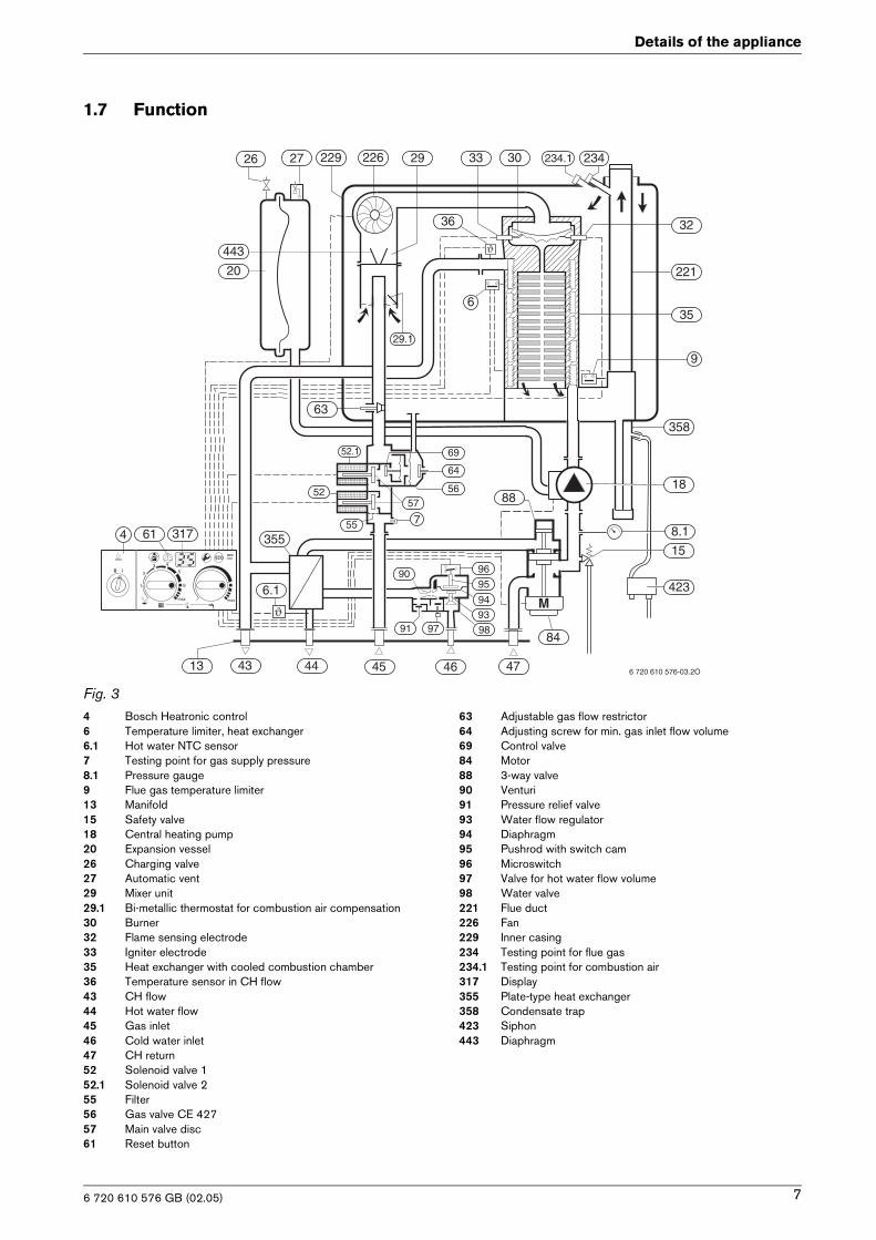
1.7 Function
Fig. 34 Bosch Heatronic control6 Temperature limiter, heat exchanger6.1 Hot water NTC sensor7 Testing point for gas supply pressure8.1 Pressure gauge9 Flue gas temperature limiter13 Manifold 15 Safety valve18 Central heating pump20 Expansion vessel26 Charging valve 27 Automatic vent29 Mixer unit29.1 Bi-metallic thermostat for combustion air compensation30 Burner32 Flame sensing electrode33 Igniter electrode35 Heat exchanger with cooled combustion chamber36 Temperature sensor in CH flow43 CH flow44 Hot water flow 45 Gas inlet46 Cold water inlet 47 CH return52 Solenoid valve 152.1 Solenoid valve 255 Filter56 Gas valve CE 42757 Main valve disc61 Reset button
63 Adjustable gas flow restrictor64 Adjusting screw for min. gas inlet flow volume69 Control valve84 Motor88 3-way valve90 Venturi91 Pressure relief valve93 Water flow regulator94 Diaphragm95 Pushrod with switch cam96 Microswitch97 Valve for hot water flow volume98 Water valve221 Flue duct226 Fan229 Inner casing 234 Testing point for flue gas234.1 Testing point for combustion air317 Display355 Plate-type heat exchanger358 Condensate trap423 Siphon443 Diaphragm
6 720 610 576 GB (02.05) 7
Details of the appliance
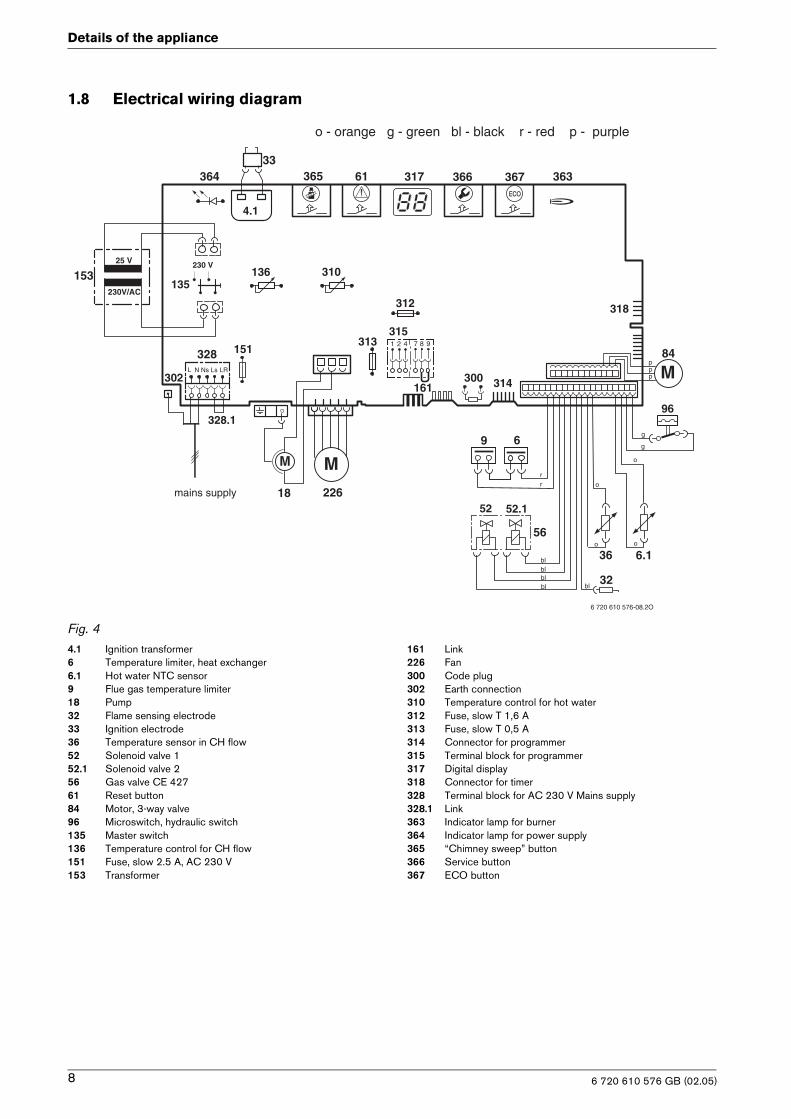
1.8 Electrical wiring diagram
Fig. 44.1 Ignition transformer6 Temperature limiter, heat exchanger6.1 Hot water NTC sensor9 Flue gas temperature limiter18 Pump32 Flame sensing electrode33 Ignition electrode36 Temperature sensor in CH flow52 Solenoid valve 152.1 Solenoid valve 256 Gas valve CE 42761 Reset button84 Motor, 3-way valve96 Microswitch, hydraulic switch 135 Master switch136 Temperature control for CH flow151 Fuse, slow 2.5 A, AC 230 V153 Transformer
161 Link 226 Fan300 Code plug302 Earth connection310 Temperature control for hot water312 Fuse, slow T 1,6 A313 Fuse, slow T 0,5 A314 Connector for programmer 315 Terminal block for programmer317 Digital display318 Connector for timer328 Terminal block for AC 230 V Mains supply 328.1 Link 363 Indicator lamp for burner364 Indicator lamp for power supply365 “Chimney sweep” button366 Service button367 ECO button
69
32
33
36
52.152
56
61
230 V
135
25 V
230V/AC
153 136
1511 2 4 7 8 9
315
161
M
226
300L N LsNs
328LR
302
310
312
313
314
317
318
363364 365 366ECO
367
4.1
328.1
M
6.1
18
96
84
M
6 720 610 576-08.2O
mains supply
rr
blblblbl bl
o o
o
o
g
g
ppp
o - orange g - green bl - black r - red p - purple
6 720 610 576 GB (02.05)8
Details of the appliance
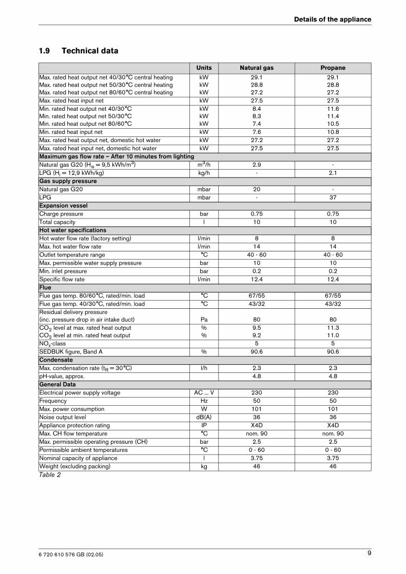
1.9 Technical data
Units Natural gas Propane
Max. rated heat output net 40/30°C central heating Max. rated heat output net 50/30°C central heatingMax. rated heat output net 80/60°C central heating
kWkWkW
29.128.827.2
29.128.827.2
Max. rated heat input net kW 27.5 27.5Min. rated heat output net 40/30°C Min. rated heat output net 50/30°CMin. rated heat output net 80/60°C
kWkWkW
8.48.37.4
11.611.410.5
Min. rated heat input net kW 7.6 10.8Max. rated heat output net, domestic hot water kW 27.2 27.2Max. rated heat input net, domestic hot water kW 27.5 27.5Maximum gas flow rate – After 10 minutes from lightingNatural gas G20 (His = 9,5 kWh/m3) m3/h 2.9 -LPG (Hi = 12,9 kWh/kg) kg/h - 2.1Gas supply pressureNatural gas G20 mbar 20 -LPG mbar - 37Expansion vesselCharge pressure bar 0.75 0.75Total capacity l 10 10Hot water specifications Hot water flow rate (factory setting) l/min 8 8Max. hot water flow rate l/min 14 14Outlet temperature range °C 40 - 60 40 - 60Max. permissible water supply pressure bar 10 10Min. inlet pressure bar 0.2 0.2Specific flow rate l/min 12.4 12.4Flue Flue gas temp. 80/60°C, rated/min. load °C 67/55 67/55Flue gas temp. 40/30°C, rated/min. load °C 43/32 43/32Residual delivery pressure(inc. pressure drop in air intake duct) Pa 80 80CO2 level at max. rated heat outputCO2 level at min. rated heat output
%%
9.59.2
11.311.0
NOx-class 5 5SEDBUK figure, Band A % 90.6 90.6CondensateMax. condensation rate (tR = 30°C) l/h 2.3 2.3pH-value, approx. 4.8 4.8General DataElectrical power supply voltage AC ... V 230 230Frequency Hz 50 50Max. power consumption W 101 101Noise output level dB(A) 36 36Appliance protection rating IP X4D X4DMax. CH flow temperature °C nom. 90 nom. 90Max. permissible operating pressure (CH) bar 2.5 2.5Permissible ambient temperatures °C 0 - 60 0 - 60Nominal capacity of appliance l 3.75 3.75Weight (excluding packing) kg 46 46Table 2
6 720 610 576 GB (02.05) 9
Details of the appliance
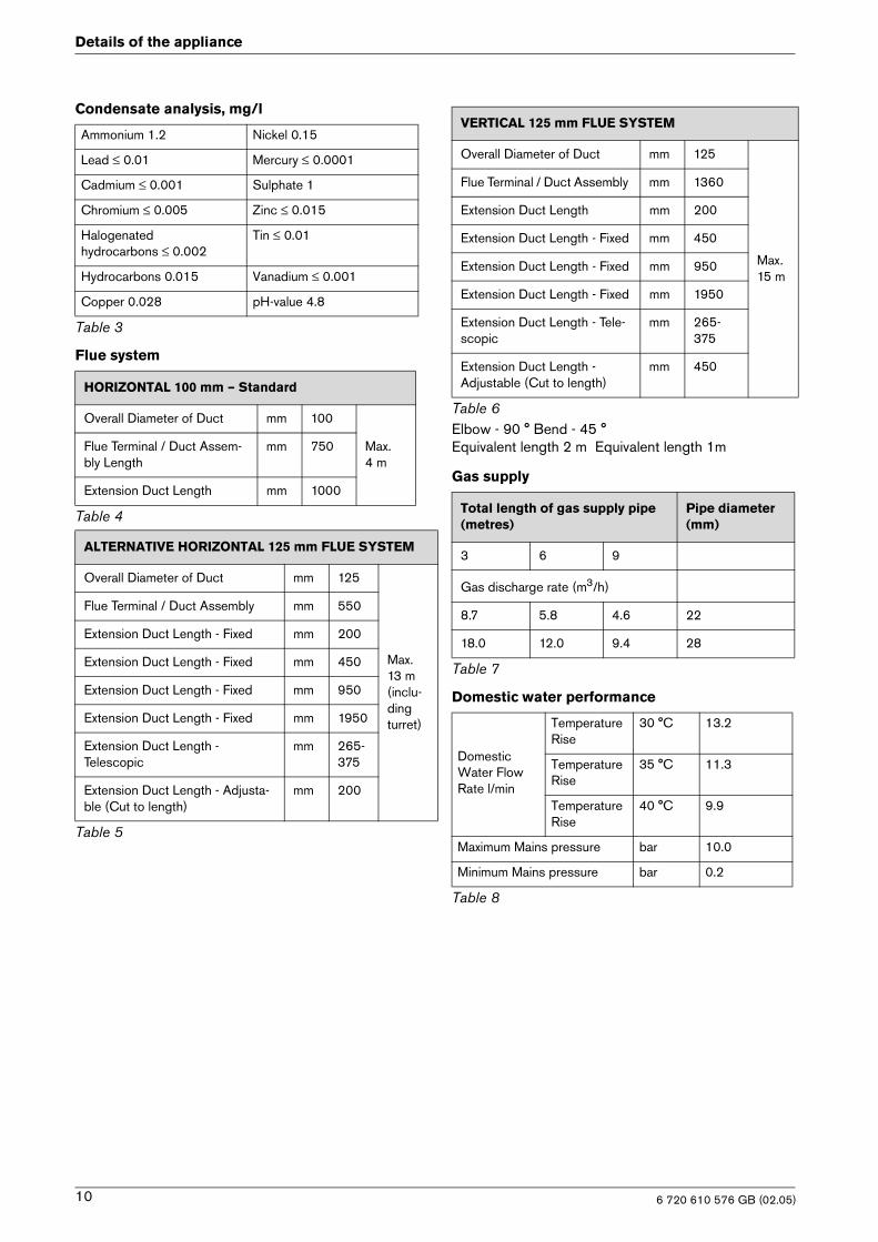
Condensate analysis, mg/l
Flue system
Elbow - 90 ° Bend - 45 °Equivalent length 2 m Equivalent length 1m
Gas supply
Domestic water performance
Ammonium 1.2 Nickel 0.15
Lead ≤ 0.01 Mercury ≤ 0.0001
Cadmium ≤ 0.001 Sulphate 1
Chromium ≤ 0.005 Zinc ≤ 0.015
Halogenatedhydrocarbons ≤ 0.002
Tin ≤ 0.01
Hydrocarbons 0.015 Vanadium ≤ 0.001
Copper 0.028 pH-value 4.8
Table 3
HORIZONTAL 100 mm – Standard
Overall Diameter of Duct mm 100
Max. 4 m
Flue Terminal / Duct Assem-bly Length
mm 750
Extension Duct Length mm 1000
Table 4
ALTERNATIVE HORIZONTAL 125 mm FLUE SYSTEM
Overall Diameter of Duct mm 125
Max. 13 m(inclu- ding turret)
Flue Terminal / Duct Assembly mm 550
Extension Duct Length - Fixed mm 200
Extension Duct Length - Fixed mm 450
Extension Duct Length - Fixed mm 950
Extension Duct Length - Fixed mm 1950
Extension Duct Length -Telescopic
mm 265-375
Extension Duct Length - Adjusta-ble (Cut to length)
mm 200
Table 5
VERTICAL 125 mm FLUE SYSTEM
Overall Diameter of Duct mm 125
Max. 15 m
Flue Terminal / Duct Assembly mm 1360
Extension Duct Length mm 200
Extension Duct Length - Fixed mm 450
Extension Duct Length - Fixed mm 950
Extension Duct Length - Fixed mm 1950
Extension Duct Length - Tele-scopic
mm 265-375
Extension Duct Length - Adjustable (Cut to length)
mm 450
Table 6
Total length of gas supply pipe (metres)
Pipe diameter (mm)
3 6 9
Gas discharge rate (m3/h)
8.7 5.8 4.6 22
18.0 12.0 9.4 28
Table 7
Domestic Water FlowRate l/min
Temperature Rise
30 °C 13.2
Temperature Rise
35 °C 11.3
Temperature Rise
40 °C 9.9
Maximum Mains pressure bar 10.0
Minimum Mains pressure bar 0.2
Table 8
6 720 610 576 GB (02.05)10
Installation regulations
2 Installation regulations
Gas Safety (Installation & Use) Regulations 1998: All gas appliances must be installed by a competent per-son. Failure to install correctly could lead to prosecu-tion.The manufacturers notes must not be taken, in any way, as overriding statutory obligations.The appliance must be installed in accordance with the current IEE Wiring Regulations, local Building Regula-tions, Building Standards (Scotland) (Consolidation), bye-laws of the local Water Company, Health and Safety Document 635 (Electricity at Work Regulations 1989) and any other local requirements.Product Liability regulations indicate that, in certain cir-cumstances, the installer can be held responsible, not only for mistakes on his part but also for damage result-ing from the use of faulty materials. We advise the installer to avoid any risk by using only quality approved branded fittings.The relevant British Standards should be followed i.e.
• BS 6798: Specification for the installation of gas fired hot water boilers of rated input not exceeding 60kW
• BS 5449: Central Heating for Domestic Premises
• BS 5546: Installation of gas hot water supplies for domestic purposes
• BS 5440:1: Flues and ventilation for gas appliances of rated input not exceeding 70 kW (gross): Flues
• BS 5440:2: Flues and ventilation for gas appliances of rated input not exceeding 60 kW (gross): Air Supply
• BS 6891: Installation of low pressure gas pipework installations up to 28mm (R1).
• BS 7074:1: Code of practice for domestic heating and hot water supply.
These instructions must be followed.
3 Installation
3.1 Important remarks
B Appliance should only be installed in sealed central heating systems.
B To avoid gas formation in the system, galvanised radi-ators or pipes must not be used.
B If a room thermostat is used: do not fit a thermostatic radiator valve on the radiator in the primary room.
B Add a suitable anti-freeze fluid compatible with alu-minium to the water in the central heating system. Suitable products are available from Betz-Dearborn Tel.: 0151 4209563 and Fernox Tel.: 01799 550811.
B In our experience, the addition of sealing agents to the water in the central heating system can cause problems (deposits in the heat exchanger). For that reason we advise against their use.
B Always turn off the gas cock before car-rying out any work on components which carry gas.
iFixing of the appliance, gas and flue con-nections, commissioning of the system and electrical connections may only be carried out by competent persons author-ised by CORGI.
6 720 610 576 GB (02.05) 11
Installation
3.2 Domestic hot water
Any regulations specified by the local water company must be observed.
The final 600 mm of the mains cold water connection to the applaince should be made in copper tube only.
The appliance is suitable for a mains supply having a maximum pressure of 10 bar. A pressure reducing valve must be fitted, if necessary.
The hot water outlet temperature is set to be capable of achieving a maximum of 60°C. The maximum tempera-ture and the frequency of the recharge of the heat store may be reset.
The maximum water flow rate is factory set at 9.9 l/min to give temperature rise of 40°C. If a higher rise is required then the flow must be reduced at the tap and the discharge temperature will rise up to the maximum set figure.
The temperature rise, upto the maximum set by the user, is automatically maintained by the modulation of the heat input. In winter, when the mains temperature is very low, the water flow, adjusted at the tap or shower, should be reduced to maintain the required delivery temperature.
It is suggested that long pipe runs to taps or showers be insulated to prevent the rapid cooling of the water.
All types of single lever mixer taps and thermostatic mixer units suitable for a mains pressure of up to 10 bar can be used.
The head of a loose-head shower must not be allowed to fall within 25 mm of the top the bath to prevent the risk of water being drawn back into the mains. Alterna-tively the shower must be fitted with an anti-syphonage device at the point of the flexible hose connections.
Over-rim bidets may be connected to the appliance pro-vided that it is in accordance with the requirements of the local water company. The outlet(s) should be shrouded and unable to have any temporary hand held spray attached. No anti-syphonage arrangements are necessary.
In exceptionally hard water areas a device to prevent scale formation may be fitted or, alternatively, the maxi-mum temperature reset to about 45°C which may reduce the risk of scale formation. The installation of a scale inhibitor assembly should be in accordance with the requirements of the local water company. Artificially softened water must not be used to fill the central heat-ing system. An isolating valve should be fitted to allow for servicing.
Devices, such as water meters or back-flow preven-tion valves, capable of preventing the flow of expan-sion water must not be fitted unless separate arrangements have been made. A Zilmet Z160 expansion vessel is the preferred type. A thread sealant compatible with potable water must be used.
3.3 Sealed systems
The appliance must not be operated without the system being full of water, properly vented and pressurised.
The expansion vessel has a volume of 10 litres and is charged to a pressure of 0.75 bar.
The water capacity of the system is shown in table 11, page 26. If a greater capacity is required then an addi-tional expansion vessel must be fitted into the system return as close to the appliance as possible. The system pressure can be set up to a maximum of 1.5 bar with 1 bar being the normal setting.
If the system pressure is greater than 2.65 bar when the appliance is operating at maximum temperature then an additional expansion vessel must be fitted into the sys-tem return as close to the appliance as possible.
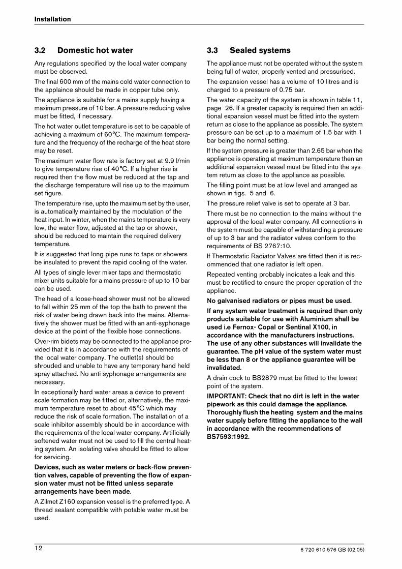
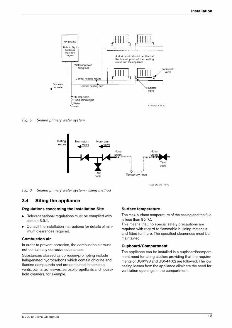
The filling point must be at low level and arranged as shown in figs. 5 and 6.
The pressure relief valve is set to operate at 3 bar.
There must be no connection to the mains without the approval of the local water company. All connections in the system must be capable of withstanding a pressure of up to 3 bar and the radiator valves conform to the requirements of BS 2767:10.
If Thermostatic Radiator Valves are fitted then it is rec-ommended that one radiator is left open.
Repeated venting probably indicates a leak and this must be rectified to ensure the proper operation of the appliance.
No galvanised radiators or pipes must be used.If any system water treatment is required then only products suitable for use with Aluminium shall be used i.e Fernox- Copal or Sentinal X100, inaccordance with the manufacturers instructions. The use of any other substances will invalidate the guarantee. The pH value of the system water must be less than 8 or the appliance guarantee will be invalidated.A drain cock to BS2879 must be fitted to the lowest point of the system.
IMPORTANT: Check that no dirt is left in the water pipework as this could damage the appliance.Thoroughly flush the heating system and the mains water supply before fitting the appliance to the wall in accordance with the recommendations of BS7593:1992.
6 720 610 576 GB (02.05)12
Installation
Fig. 5 Sealed primary water system
Fig. 6 Sealed primary water system - filling method
3.4 Siting the appliance
Regulations concerning the Installation Site
B Relevant national regulations must be complied with section 3.9.1.
B Consult the installation instructions for details of min-imum clearances required.
Combustion air
In order to prevent corrosion, the combustion air must not contain any corrosive substances.
Substances classed as corrosion-promoting include halogenated hydrocarbons which contain chlorine and fluorine compounds and are contained in some sol-vents, paints, adhesives, aerosol propellants and house-hold cleaners, for example.
Surface temperature
The max. surface temperature of the casing and the flue is less than 85 °C. This means that, no special safety precautions are required with regard to flammable building materials and fitted furniture. The specified clearences must be maintained.
Cupboard/Compartment
The appliance can be installed in a cupboard/compart-ment need for airing clothes providing that the require-ments of BS6798 and BS5440:2 are followed. The low casing losses from the appliance eliminate the need for ventilation openings in the compartment.
Domestichot water Central heating flow
Radiatorvalve
Lockshieldvalve
Central heating return
A drain cock should be fitted atthe lowest point of the heatingcircuit and the appliance
Watermain
BS stop valve.Fixed spindle type
APPLIANCE
Refer to Fig.1Appliancewater flow diagram
WRC approvedfilling loop
6 720 610 576 -09.2O
Heatingreturn
Non-returnvalve
Non-returnvalve
Hoseunion
Hoseunion
Testcock
Temporary hoseTestcock
6 720 610 576 - 10.1O
6 720 610 576 GB (02.05) 13
Installation
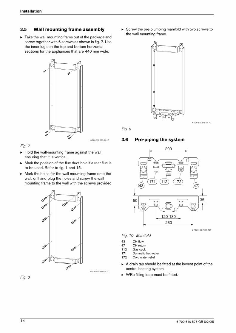
3.5 Wall mounting frame assembly
B Take the wall mounting frame out of the package and screw together with 6 screws as shown in fig. 7. Use the inner lugs on the top and bottom horizontalsections for the appliances that are 440 mm wide.
Fig. 7
B Hold the wall-mounting frame against the wall ensuring that it is vertical.
B Mark the position of the flue duct hole if a rear flue is to be used. Refer to fig. 1 and 15.
B Mark the holes for the wall mounting frame onto the wall, drill and plug the holes and screw the wall mounting frame to the wall with the screws provided.
Fig. 8
B Screw the pre-plumbing manifold with two screws to the wall mounting frame.
Fig. 9
3.6 Pre-piping the system
Fig. 10 Manifold43 CH flow47 CH return112 Gas cock 171 Domestic hot water172 Cold water relief
B A drain tap should be fitted at the lowest point of the central heating system.
B WRc filling loop must be fitted.
6 720 610 576-04.1O
6 720 610 576-05.1O
6 720 610 576-11.1O
200
260
6 720 610 576-06.1O
35
120-130
50
4743172112171
6 720 610 576 GB (02.05)14
Installation
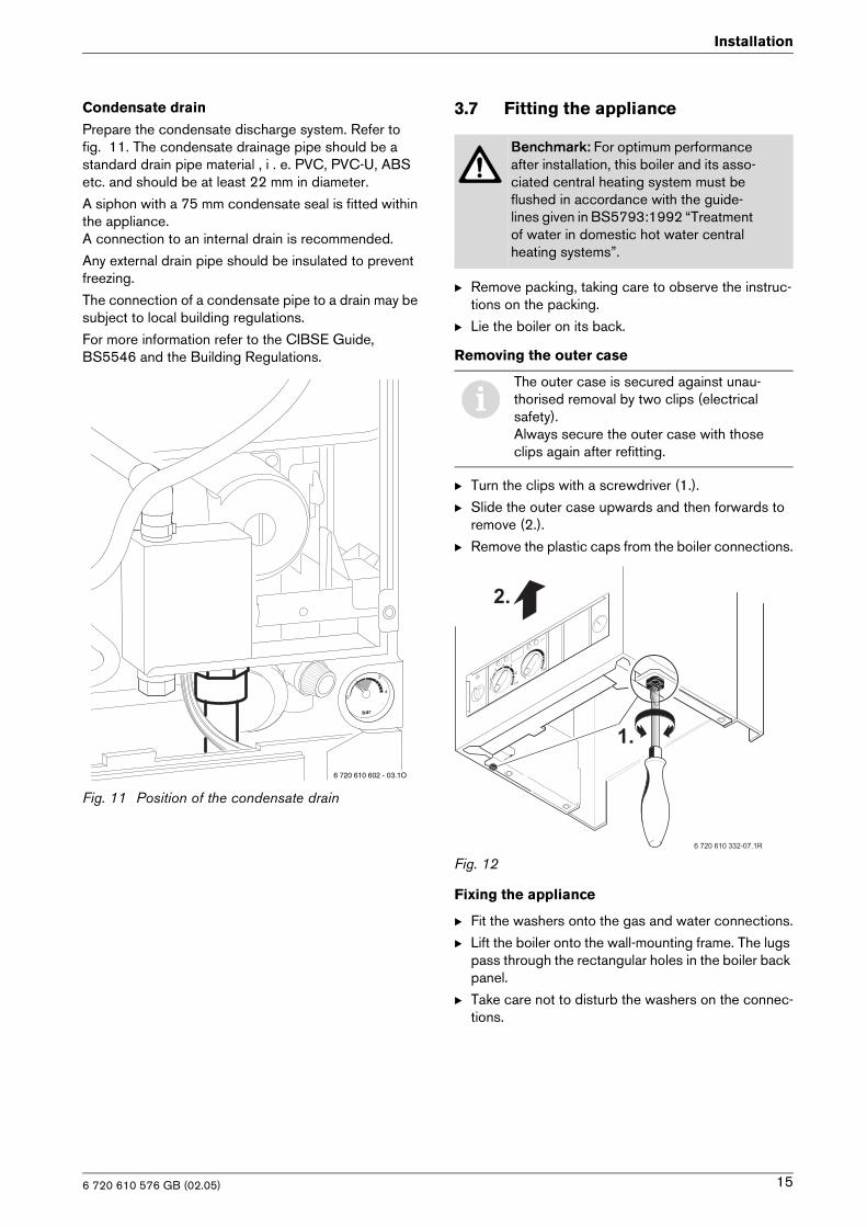
Condensate drain
Prepare the condensate discharge system. Refer to fig. 11. The condensate drainage pipe should be a standard drain pipe material , i . e. PVC, PVC-U, ABS etc. and should be at least 22 mm in diameter.
A siphon with a 75 mm condensate seal is fitted within the appliance. A connection to an internal drain is recommended.
Any external drain pipe should be insulated to prevent freezing.
The connection of a condensate pipe to a drain may be subject to local building regulations.
For more information refer to the CIBSE Guide, BS5546 and the Building Regulations.
Fig. 11 Position of the condensate drain
3.7 Fitting the appliance
B Remove packing, taking care to observe the instruc-tions on the packing.
B Lie the boiler on its back.
Removing the outer case
B Turn the clips with a screwdriver (1.).
B Slide the outer case upwards and then forwards to remove (2.).
B Remove the plastic caps from the boiler connections.
Fig. 12
Fixing the appliance
B Fit the washers onto the gas and water connections.
B Lift the boiler onto the wall-mounting frame. The lugs pass through the rectangular holes in the boiler back panel.
B Take care not to disturb the washers on the connec-tions.
6 720 610 602 - 03.1O
Benchmark: For optimum performance after installation, this boiler and its asso-ciated central heating system must be flushed in accordance with the guide-lines given in BS5793:1992 “Treatment of water in domestic hot water central heating systems”.
iThe outer case is secured against unau-thorised removal by two clips (electrical safety).Always secure the outer case with those clips again after refitting.
��
��
������������������
6 720 610 576 GB (02.05) 15
Installation
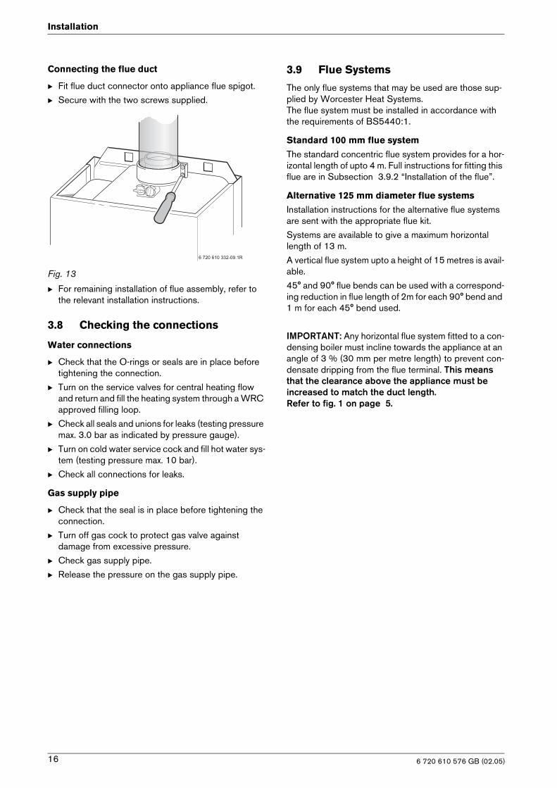
Connecting the flue duct
B Fit flue duct connector onto appliance flue spigot.
B Secure with the two screws supplied.
Fig. 13
B For remaining installation of flue assembly, refer to the relevant installation instructions.
3.8 Checking the connections
Water connections
B Check that the O-rings or seals are in place before tightening the connection.
B Turn on the service valves for central heating flow and return and fill the heating system through a WRC approved filling loop.
B Check all seals and unions for leaks (testing pressure max. 3.0 bar as indicated by pressure gauge).
B Turn on cold water service cock and fill hot water sys-tem (testing pressure max. 10 bar).
B Check all connections for leaks.
Gas supply pipe
B Check that the seal is in place before tightening the connection.
B Turn off gas cock to protect gas valve againstdamage from excessive pressure.
B Check gas supply pipe.
B Release the pressure on the gas supply pipe.
3.9 Flue Systems
The only flue systems that may be used are those sup-plied by Worcester Heat Systems.The flue system must be installed in accordance with the requirements of BS5440:1.
Standard 100 mm flue system
The standard concentric flue system provides for a hor-izontal length of upto 4 m. Full instructions for fitting this flue are in Subsection 3.9.2 “Installation of the flue”.
Alternative 125 mm diameter flue systems
Installation instructions for the alternative flue systems are sent with the appropriate flue kit.
Systems are available to give a maximum horizontal length of 13 m.
A vertical flue system upto a height of 15 metres is avail-able.
45° and 90° flue bends can be used with a correspond-ing reduction in flue length of 2m for each 90° bend and 1 m for each 45° bend used.
IMPORTANT: Any horizontal flue system fitted to a con-densing boiler must incline towards the appliance at an angle of 3 % (30 mm per metre length) to prevent con-densate dripping from the flue terminal. This means that the clearance above the appliance must be increased to match the duct length.Refer to fig. 1 on page 5.
�����������������
��
�
�
6 720 610 576 GB (02.05)16
Installation
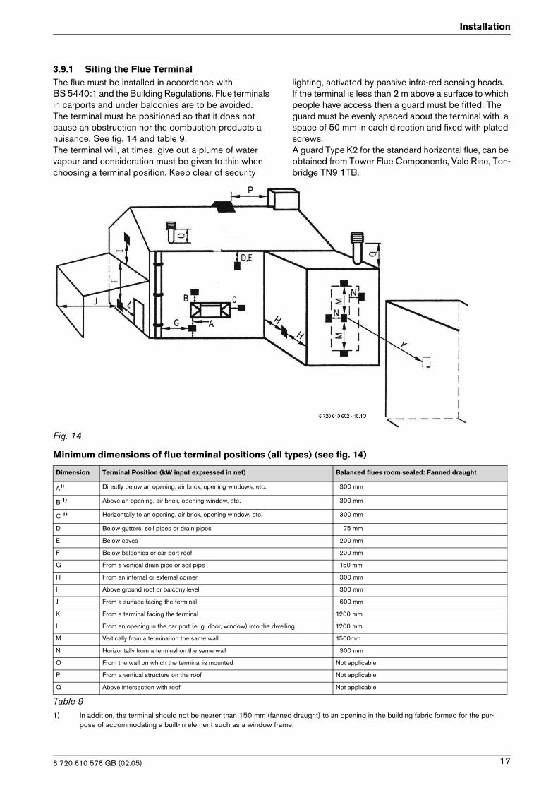
3.9.1 Siting the Flue TerminalThe flue must be installed in accordance with BS 5440:1 and the Building Regulations. Flue terminals in carports and under balconies are to be avoided.The terminal must be positioned so that it does not cause an obstruction nor the combustion products a nuisance. See fig. 14 and table 9. The terminal will, at times, give out a plume of water vapour and consideration must be given to this when choosing a terminal position. Keep clear of security
lighting, activated by passive infra-red sensing heads.If the terminal is less than 2 m above a surface to which people have access then a guard must be fitted. The guard must be evenly spaced about the terminal with a space of 50 mm in each direction and fixed with plated screws. A guard Type K2 for the standard horizontal flue, can be obtained from Tower Flue Components, Vale Rise, Ton-bridge TN9 1TB.
Fig. 14
Minimum dimensions of flue terminal positions (all types) (see fig. 14)
Dimension Terminal Position (kW input expressed in net) Balanced flues room sealed: Fanned draught
A1) Directly below an opening, air brick, opening windows, etc. 300 mm
B 1) Above an opening, air brick, opening window, etc. 300 mm
C 1) Horizontally to an opening, air brick, opening window, etc. 300 mm
D Below gutters, soil pipes or drain pipes 75 mm
E Below eaves 200 mm
F Below balconies or car port roof 200 mm
G From a vertical drain pipe or soil pipe 150 mm
H From an internal or external corner 300 mm
I Above ground roof or balcony level 300 mm
J From a surface facing the terminal 600 mm
K From a terminal facing the terminal 1200 mm
L From an opening in the car port (e. g. door, window) into the dwelling 1200 mm
M Vertically from a terminal on the same wall 1500mm
N Horizontally from a terminal on the same wall 300 mm
O From the wall on which the terminal is mounted Not applicable
P From a vertical structure on the roof Not applicable
Q Above intersection with roof Not applicable
Table 91) In addition, the terminal should not be nearer than 150 mm (fanned draught) to an opening in the building fabric formed for the pur-
pose of accommodating a built-in element such as a window frame.
6 720 610 576 GB (02.05) 17
Installation
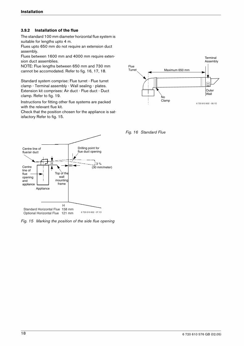
3.9.2 Installation of the flue
The standard 100 mm diameter horizontal flue system is suitable for lengths upto 4 m. Flues upto 650 mm do not require an extension duct assembly. Flues between 1600 mm and 4000 mm require exten-sion duct assemblies.NOTE: Flue lengths between 650 mm and 730 mm cannot be accomodated. Refer to fig. 16, 17, 18.
Standard system comprise: Flue turret - Flue turret clamp - Terminal assembly - Wall sealing - plates.Extension kit comprises: Air duct - Flue duct - Duct clamp. Refer to fig. 19.
Instructions for fitting other flue systems are packed with the relevant flue kit.Check that the position chosen for the appliance is sat-isfactory Refer to fig. 15.
Fig. 15 Marking the position of the side flue opening
Fig. 16 Standard Flue
Appliance
120
Drilling point forflue duct opening
3 %(30 mm/meter)Centre
line offlueopeningandappliance
Centre line offlue/air duct
Top of thewall
mountingframe
H
H Standard Horizontal Flue 158 mmOptional Horizontal Flue 121 mm 6 720 610 602 - 07.1O
FlueTurret
No Clamp
Maximum 650 mm
TerminalAssembly
OuterWall
6 720 610 602 - 08.1O
6 720 610 576 GB (02.05)18
Installation
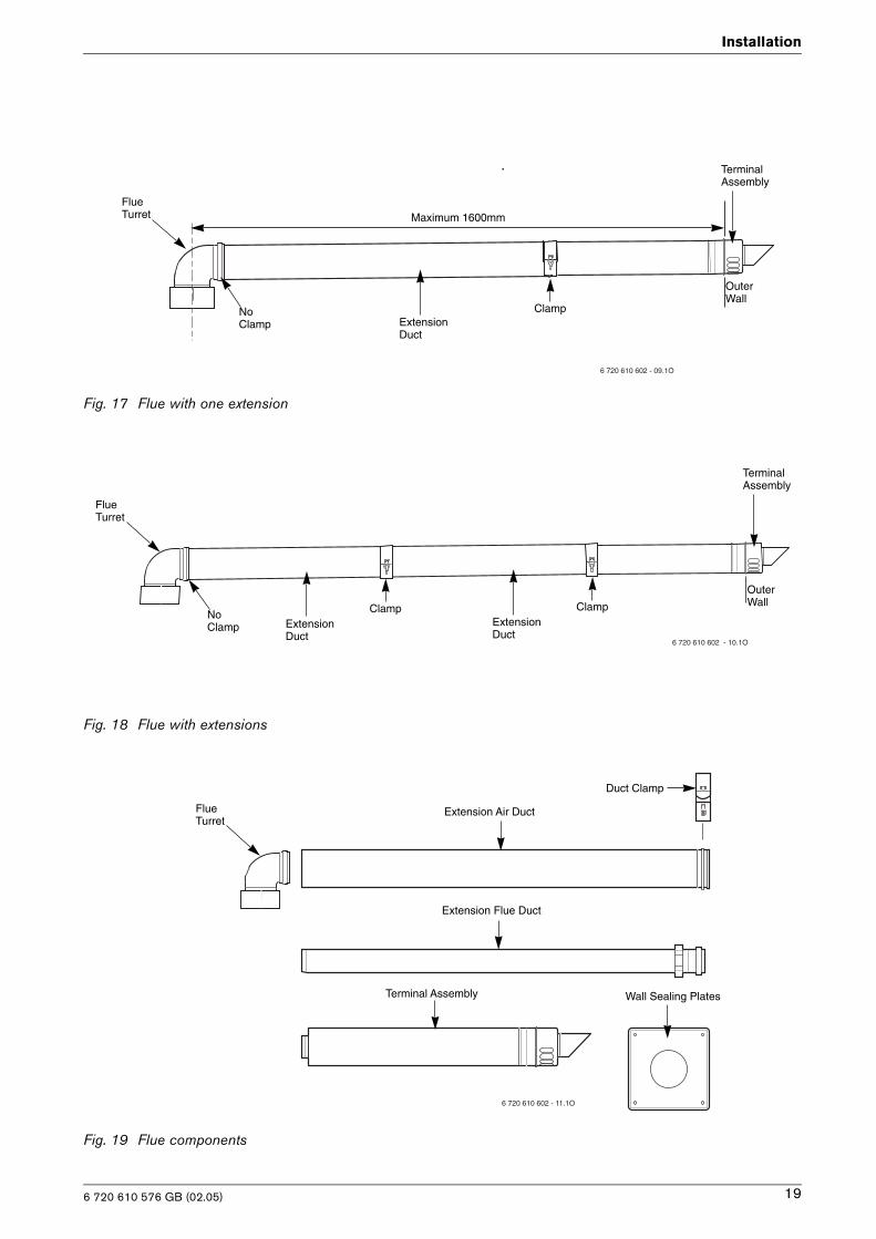
Fig. 17 Flue with one extension
Fig. 18 Flue with extensions
Fig. 19 Flue components
Maximum 1600mmFlueTurret
No Clamp
TerminalAssembly
OuterWall
Extension Duct
6 720 610 602 - 09.1O
Clamp
FlueTurret
No Clamp
ClampExtension Duct
ClampExtension Duct
TerminalAssembly
OuterWall
6 720 610 602 - 10.1O
Extension Air Duct
Extension Flue Duct
Terminal Assembly
Duct Clamp
Wall Sealing Plates
6 720 610 602 - 11.1O
FlueTurret
6 720 610 576 GB (02.05) 19
Installation
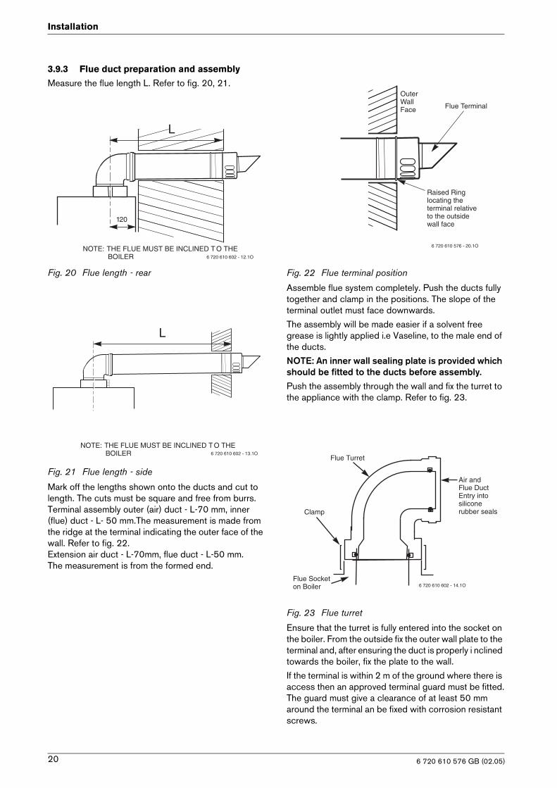
3.9.3 Flue duct preparation and assembly
Measure the flue length L. Refer to fig. 20, 21.
Fig. 20 Flue length - rear
Fig. 21 Flue length - side
Mark off the lengths shown onto the ducts and cut to length. The cuts must be square and free from burrs.Terminal assembly outer (air) duct - L-70 mm, inner (flue) duct - L- 50 mm.The measurement is made from the ridge at the terminal indicating the outer face of the wall. Refer to fig. 22.Extension air duct - L-70mm, flue duct - L-50 mm.The measurement is from the formed end.
Fig. 22 Flue terminal position
Assemble flue system completely. Push the ducts fully together and clamp in the positions. The slope of the terminal outlet must face downwards.
The assembly will be made easier if a solvent free grease is lightly applied i.e Vaseline, to the male end of the ducts.
NOTE: An inner wall sealing plate is provided which should be fitted to the ducts before assembly.Push the assembly through the wall and fix the turret to the appliance with the clamp. Refer to fig. 23.
Fig. 23 Flue turret
Ensure that the turret is fully entered into the socket on the boiler. From the outside fix the outer wall plate to the terminal and, after ensuring the duct is properly i nclined towards the boiler, fix the plate to the wall.
If the terminal is within 2 m of the ground where there is access then an approved terminal guard must be fitted.The guard must give a clearance of at least 50 mm around the terminal an be fixed with corrosion resistant screws.
NOTE: THE FLUE MUST BE INCLINED T O THE BOILER
L
120
6 720 610 602 - 12.1O
NOTE: THE FLUE MUST BE INCLINED T O THE BOILER
L
6 720 610 602 - 13.1O
OuterWallFace Flue Terminal
Raised Ringlocating theterminal relativeto the outsidewall face
6 720 610 576 - 20.1O
Air and Flue Duct Entry intosilicone rubber seals
Flue Turret
Clamp
Flue Socket on Boiler 6 720 610 602 - 14.1O
6 720 610 576 GB (02.05)20
Electrical connections
4 Electrical connections
All control and safety systems are built into the appli-ance.
B Allow mains cable to protrude at least 50 cm from wall.
B To make splash-water proof (IP): cut the cable grom-met hole size to match diameter of cable, see fig. 26.
It must be possible to isolate the appliance. The appli-ance must be earthed.
The appliance must be connected to the mains through a 6 A double pole isolator with a contact separation 3 mm in all poles and supplying the appliance and con-trols only. The wiring must comply with the current requirements of the IEE Wiring Regulations and any local regulations which apply.
• Supply: 230 V ~ 50 Hz, 140 Watts
• Mains cable: PVC insulated 0.75 mm2 (24 x 0.20 mm) to BS6500-Table 6. Temperature rated 100°C.
• Protection IPX4D
• External fuse 3 A.
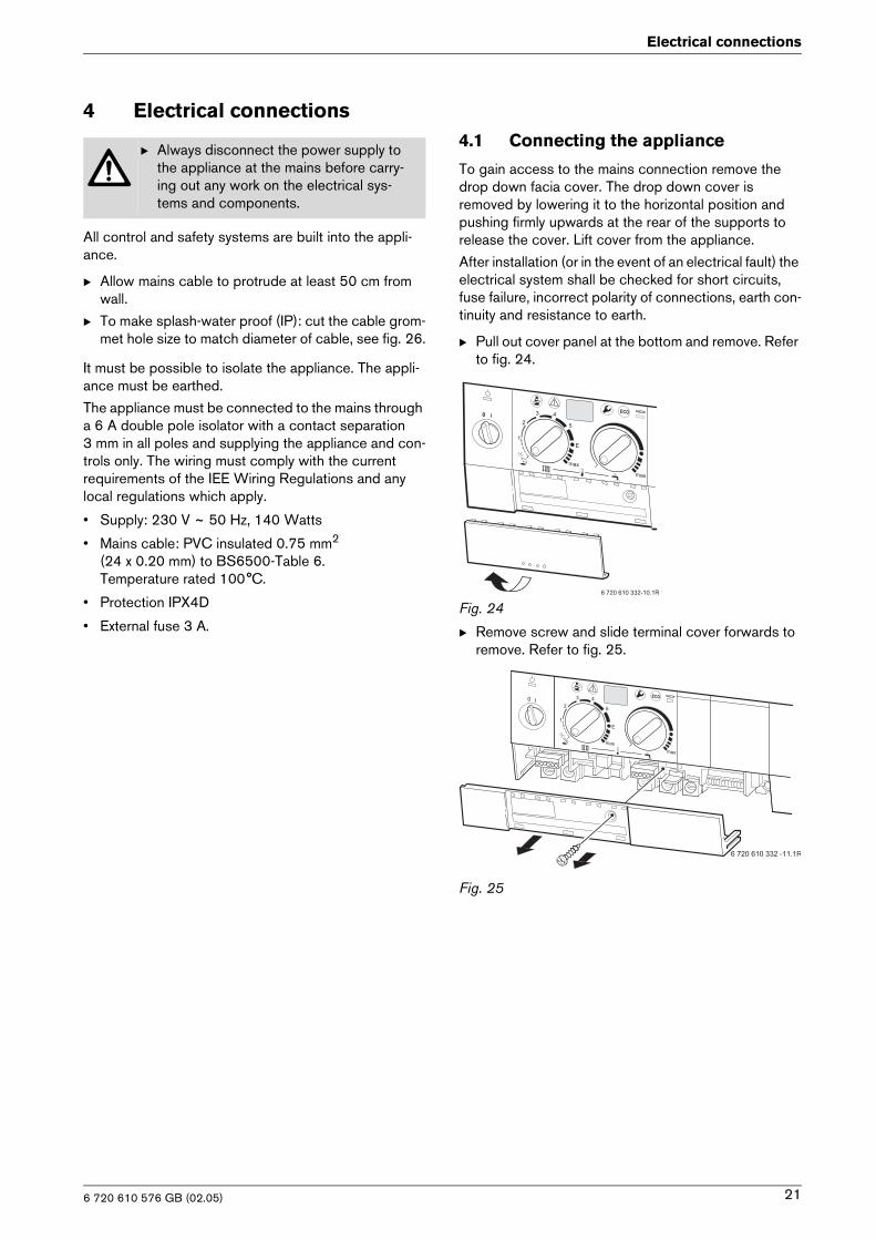
4.1 Connecting the appliance
To gain access to the mains connection remove the drop down facia cover. The drop down cover is removed by lowering it to the horizontal position and pushing firmly upwards at the rear of the supports to release the cover. Lift cover from the appliance.
After installation (or in the event of an electrical fault) the electrical system shall be checked for short circuits, fuse failure, incorrect polarity of connections, earth con-tinuity and resistance to earth.
B Pull out cover panel at the bottom and remove. Refer to fig. 24.
Fig. 24
B Remove screw and slide terminal cover forwards to remove. Refer to fig. 25.
Fig. 25
B Always disconnect the power supply to the appliance at the mains before carry-ing out any work on the electrical sys-tems and components.
�
�
�
� �
�
�����������������
�
�
�
� �
�
������������������
6 720 610 576 GB (02.05) 21
Electrical connections
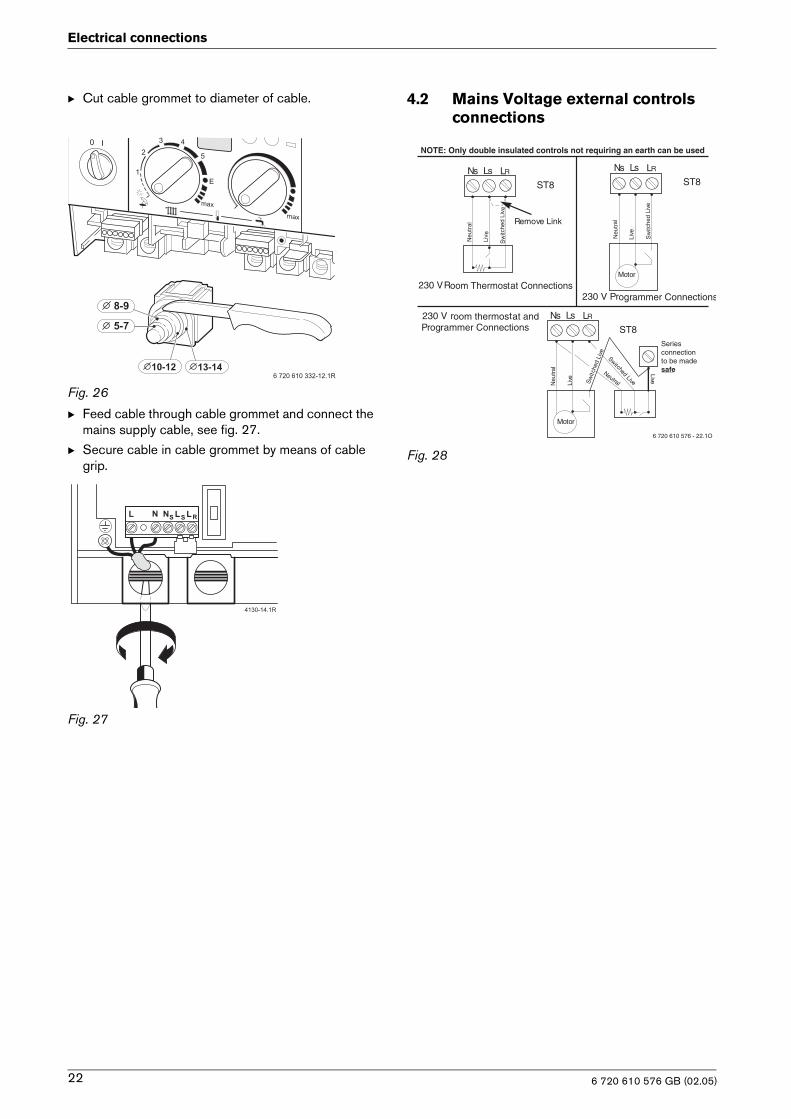
B Cut cable grommet to diameter of cable.
Fig. 26
B Feed cable through cable grommet and connect the mains supply cable, see fig. 27.
B Secure cable in cable grommet by means of cable grip.
Fig. 27
4.2 Mains Voltage external controls connections
Fig. 28
�
�
�
� �
�
���������������������������
��
��
� � ��� �
��������
230 V Room Thermostat Connections
Ns Ls LR
ST8Ns Ls LR
ST8
Remove Link
Neu
tral
Liv e
Sw
itche
d Li
v e
Neu
tral
Live
Sw
itche
d Li
ve
Motor
230 V Programmer Connections
230 V room thermostat andProgrammer Connections
Ns Ls LR
ST8
Neu
tral
Live
Neutral
Live
Swit ched Live
Motor
Sw
itche
d Li
ve
Series connectionto be madesafe
NOTE: Only double insulated controls not requiring an earth can be used
6 720 610 576 - 22.1O
6 720 610 576 GB (02.05)22
Commissioning
5 Commissioning
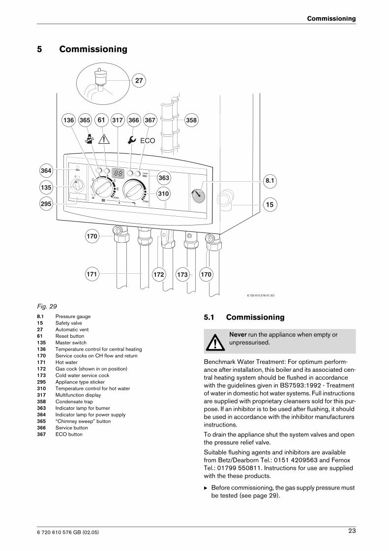
Fig. 298.1 Pressure gauge15 Safety valve27 Automatic vent61 Reset button135 Master switch136 Temperature control for central heating170 Service cocks on CH flow and return171 Hot water172 Gas cock (shown in on position)173 Cold water service cock295 Appliance type sticker310 Temperature control for hot water317 Multifunction display358 Condensate trap363 Indicator lamp for burner364 Indicator lamp for power supply365 “Chimney sweep” button366 Service button367 ECO button
5.1 Commissioning
Benchmark Water Treatment: For optimum perform-ance after installation, this boiler and its associated cen-tral heating system should be flushed in accordance with the guidelines given in BS7593:1992 - Treatment of water in domestic hot water systems. Full instructions are supplied with proprietary cleansers sold for this pur-pose. If an inhibitor is to be used after flushing, it should be used in accordance with the inhibitor manufacturers instructions.
To drain the appliance shut the system valves and open the pressure relief valve.
Suitable flushing agents and inhibitors are available from Betz/Dearborn Tel.: 0151 4209563 and Fernox Tel.: 01799 550811. Instructions for use are supplied with the these products.
B Before commissioning, the gas supply pressure must be tested (see page 29).
365 61 317 366 367
ECO
364
135
295
136
170
171
E
6 720 610 576-07.2O
15
310
363
358
8.1
173 170172
27
Never run the appliance when empty or unpressurised.
6 720 610 576 GB (02.05) 23
Commissioning
B Unscrew the condensation trap (358) and pull out, fill with approx. 1/4 l of water and refit. Refer to fig. 29.
B Adjust charge pressure of expansion vessel to static head of the central heating system (see page 26).
B Open all system radiator valves.
B Turn on service valves (170), fill central heating sys-tem to pressure of 1 - 2 bar through the WRc approved filling loop. Refer to fig. 29.
B Vent radiators.
B Refill heating system and set the pressure to 1 bar.
B Turn on cold water service cock (173). Refer to fig. 29.
B Check that the gas type specified on the identifica-tion plate matches that of the gas supply.
B Turn on gas cock (172). Refer to fig. 29.
5.2 Switching the appliance on/off
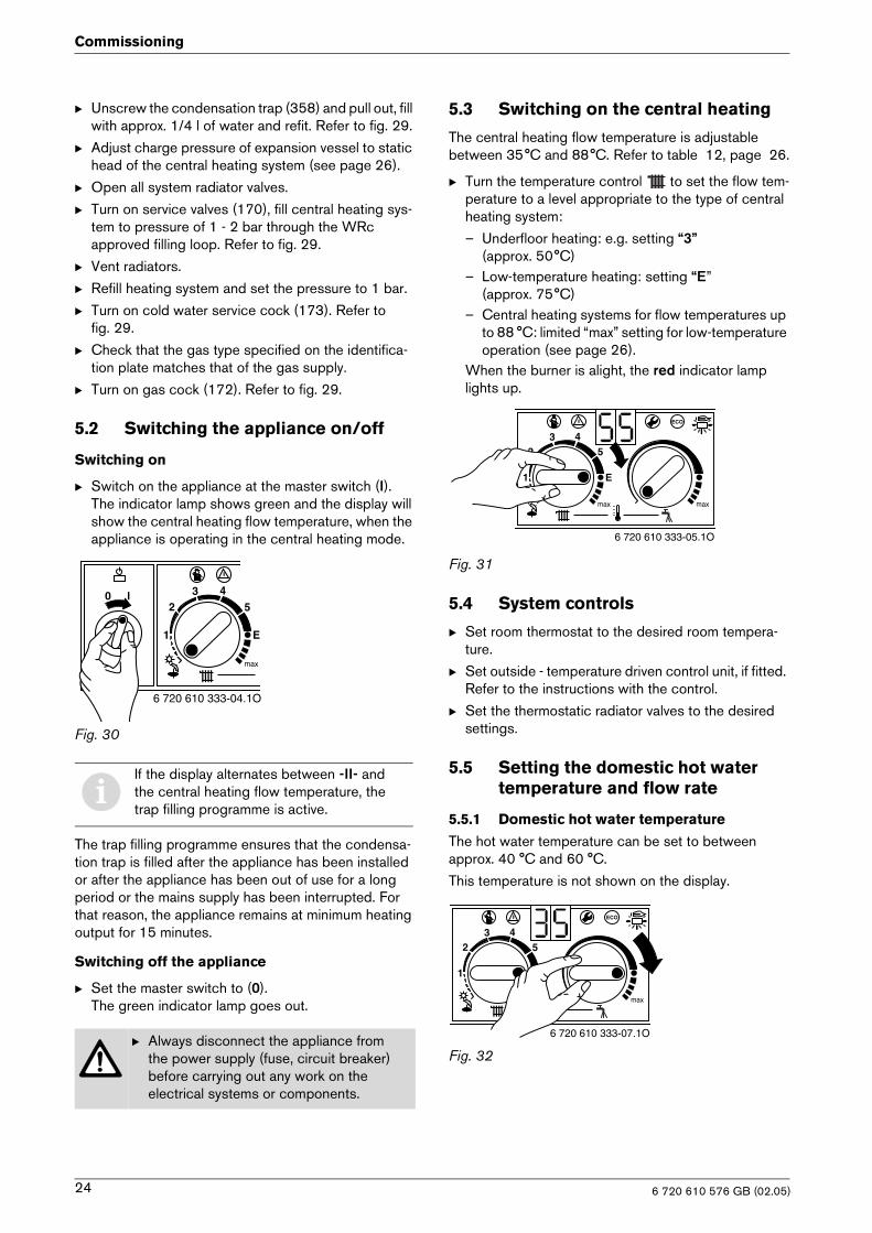
Switching on
B Switch on the appliance at the master switch (I).The indicator lamp shows green and the display will show the central heating flow temperature, when the appliance is operating in the central heating mode.
Fig. 30
The trap filling programme ensures that the condensa-tion trap is filled after the appliance has been installed or after the appliance has been out of use for a long period or the mains supply has been interrupted. For that reason, the appliance remains at minimum heating output for 15 minutes.
Switching off the appliance
B Set the master switch to (0).The green indicator lamp goes out.
5.3 Switching on the central heating
The central heating flow temperature is adjustable between 35°C and 88°C. Refer to table 12, page 26.
B Turn the temperature control to set the flow tem-perature to a level appropriate to the type of central heating system:
– Underfloor heating: e.g. setting “3” (approx. 50°C)
– Low-temperature heating: setting “E” (approx. 75°C)
– Central heating systems for flow temperatures up to 88 °C: limited “max” setting for low-temperature operation (see page 26).
When the burner is alight, the red indicator lamp lights up.
Fig. 31
5.4 System controls
B Set room thermostat to the desired room tempera-ture.
B Set outside - temperature driven control unit, if fitted. Refer to the instructions with the control.
B Set the thermostatic radiator valves to the desired settings.
5.5 Setting the domestic hot water temperature and flow rate
5.5.1 Domestic hot water temperature
The hot water temperature can be set to between approx. 40 °C and 60 °C.
This temperature is not shown on the display.
Fig. 32
iIf the display alternates between -II- and the central heating flow temperature, the trap filling programme is active.
B Always disconnect the appliance from the power supply (fuse, circuit breaker) before carrying out any work on the electrical systems or components.
6 720 610 333-04.1O
6 720 610 333-05.1O
6 720 610 333-07.1O
6 720 610 576 GB (02.05)24
Commissioning
“ECO” button
By pressing and holding the “ECO” button until the display lights, you can switch between Comfort mode and Economy mode.
Comfort mode: button is not lit (factory setting)
The appliance is held constantly at the set temperature. This means that hot water is available almost instanta-neously at the tap. Consequently the appliance will switch on at intervals, even if no hot water is being drawn.
ECO mode with demand detection, button is lit
The demand detection function enables maximum gas and water economy. Briefly turning a hot water tap on and then off again sig-nals demand to the appliance which then heats up the water to the set temperature.Hot water is thus available in about 1 minute.
ECO mode, button is lit
Water is not heated up until hot water is drawn. This means that there is a longer waiting period before hot water is available.
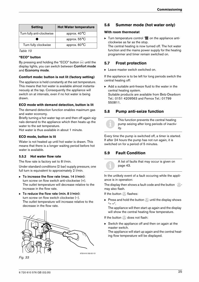
5.5.2 Hot water flow rate
The flow rate is factory set to 8 l/min.
Under standard conditions (2 bar) supply pressure, one full turn is equivalent to approximately 2 l/min.
B To increase the flow rate (max. 14 l/min):turn screw on flow switch anti-clockwise (+).The outlet temperature will decrease relative to the increase in the flow rate.
B To reduce the flow rate (min. 8 l/min):turn screw on flow switch clockwise (–).The outlet temperature will increase relative to the decrease in the flow rate.
Fig. 33
5.6 Summer mode (hot water only)
With room thermostat
B Turn temperature control on the appliance anti-clockwise as far as the stop.The central heating is now turned off. The hot water function and the mains power supply for the heating programmer and timer remain switched on.
5.7 Frost protection
B Leave master switch switched on.
If the appliance is to be left for long periods switch the central heating off:
B Add a suitable anti-freeze fluid to the water in the central heating system. Suitable products are available from Betz-Dearborn Tel.: 0151 4209563 and Fernox Tel.: 01799 550811.
5.8 Pump anti-seize function
Every time the pump is switched off, a timer is started. If after 24 hours the pump has not run again, it is switched on for a period of 5 minutes.
5.9 Fault Condition
In the unlikely event of a fault occuring while the appli-ance is in operation:
The display then shows a fault code and the button -may also flash.
If the button flashes:
B Press and hold the button until the display shows “– –”.The appliance will then start up again and the display will show the central heating flow temperature.
If the button does not flash:
B Switch the appliance off and then on again at the master switch.The appliance will start up again and the central heat-ing flow temperature will be displayed.
Setting Hot Water temperature
Turn fully anti-clockwise approx. 40°C
� approx. 55°C
Turn fully clockwise approx. 60°C
Table 10
6720 610 332-25.1O
iThis function prevents the central heating pump seizing after long periods of inactiv-ity.
iA list of faults that may occur is given on page 43.
6 720 610 576 GB (02.05) 25
Individual settings
6 Individual settings
6.1 Mechanical settings
6.1.1 Checking the size of the expansion vessel
Maximum pressure at maximum CH flow temperature is 2.5 bar. If the pressure is greater than this then fit an extra expansion vessel. Refer to table 11.
System Capacity – BS7074:1
6.1.2 Setting the central heating flow tempera-ture
The central heating flow temperature can be set to between 35°C and 88°C.
Limited maximum setting for low-temperature operation
The temperature control is factory limited to setting E, giving a maximum flow temperature of 75°C.
Adjustment of the heating output to the calculated heat demand is not required by the heating systems regula-tions.
Removing the maximum setting limit
For heating systems which require higher flow tempera-tures, the maximum setting limit can be removed.
B Lift off the yellow button on the temperature control with a screwdriver.
Fig. 34
B Rotate yellow button through 180° and replace (dot facing inwards).The CH flow temperature is no longer limited.
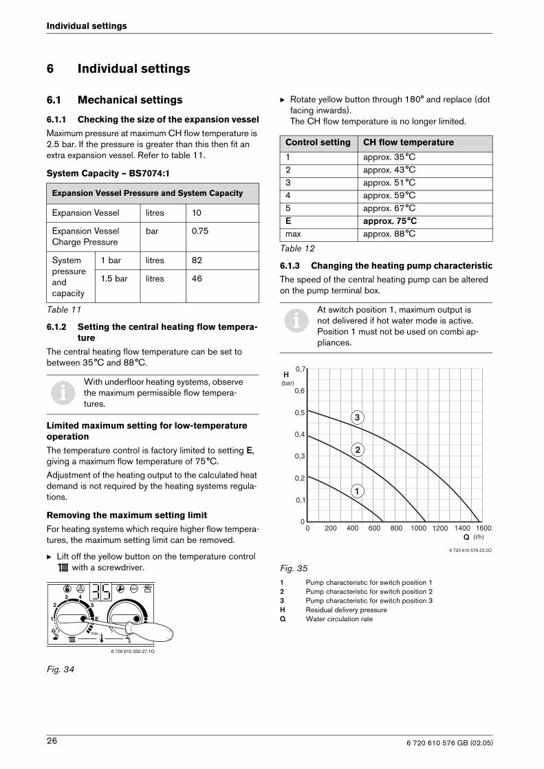
6.1.3 Changing the heating pump characteristic
The speed of the central heating pump can be altered on the pump terminal box.
Fig. 351 Pump characteristic for switch position 12 Pump characteristic for switch position 23 Pump characteristic for switch position 3H Residual delivery pressureQ Water circulation rate
Expansion Vessel Pressure and System Capacity
Expansion Vessel litres 10
Expansion Vessel Charge Pressure
bar 0.75
System pressure and capacity
1 bar litres 82
1.5 bar litres 46
Table 11
iWith underfloor heating systems, observe the maximum permissible flow tempera-tures.
6 720 610 332-27.1O
Control setting CH flow temperature
1 approx. 35°C2 approx. 43°C3 approx. 51°C4 approx. 59°C5 approx. 67°CE approx. 75°Cmax approx. 88°C
Table 12
iAt switch position 1, maximum output is not delivered if hot water mode is active. Position 1 must not be used on combi ap-pliances.
200 400 600 800 1200 14001000 1600
0,7
0
0,6
0,5
0,4
0,3
0,2
0,1
0
(bar)H
Q (l/h)
3
2
1
6 720 610 576-23.2O
6 720 610 576 GB (02.05)26
Individual settings
6.2 Settings on the Bosch Heatronic
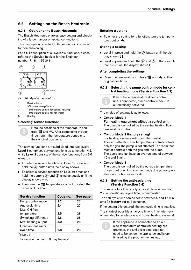
6.2.1 Operating the Bosch Heatronic
The Bosch Heatronic enables easy setting and check-ing of a large number of appliance functions.
This description is limited to those functions required for commissioning.
For a full description of all available functions, please refer to the Service booklet for the Engineer, number 7 181 465 346.
Fig. 36 Appliance controls1 Service button2 “Chimney sweep” button3 Temperature control for central heating4 Temperature control for hot water5 Display
Selecting service function:
The service functions are subdivided into two levels:Level 1 comprises service functions up to function 4.9, while Level 2 consists of the service functions from 5.0 upwards.
B To select a service function on Level 1: press and hold the button until the display shows – –.
B To select a service function on Level 2: press and hold the buttons and simultaneously until the display shows = =.
B Then turn the temperature control to select the required function.
The service function 5.0 may be reset.
Entering a setting
B To enter the setting for a function, turn the tempera-ture control .
Storing a setting
B Level 1: press and hold the button until the dis-play shows [ ].
B Level 2: press and hold the and buttons simul-taneously until the display shows [ ].
After completing the settings
B Reset the temperature controls and to their original positions.
6.2.2 Selecting the pump control mode for cen-tral heating mode (Service Function 2.2)
The choice of settings is as follows:
• Control Mode 1For heating equipment without a control unit.The pump is controlled by the central heating flow temperature control.
• Control Mode 2 (factory setting)For heating systems with room thermostat. The central heating flow temperature control controls only the gas, the pump is not affected. The room ther-mostat controls both the gas and the pump.The pump and fan have an overrun time of between 15 s and 3 min.
• Control Mode 3The pump is controlled by the outside temperature driven control unit. In summer mode, the pump oper-ates only for hot water mode.
6.2.3 Setting the anti-cycle time(Service Function 2.4)
This service function is only active if Service Function 2.7, automatic anti-cycle time, is deactivated.
The anti-cycle time can be set to between 0 and 15 min-utes (is factory set to 3 minutes).
If the setting 0 is entered, the anti-cycle time is inactive.
The shortest possible anti-cycle time is 1 minute (rec-ommended for single-pipe and hot-air heating systems).
iNote the positions of the temperature con-trols and . After completing the set-tings, return the temperature controls to their original positions.
Service function Code no. See page
Pump control mode 2.2 27Anti-cycle time 2.4 27Max. CH flowtemperature 2.5 28Switching difference 2.6 28Max. heating output 5.0 28Constant hot water cycle time 6.8 28
Table 13
6 720 610 332-30.1O
52 1
43
iIf an outside temperature driven control unit is connected, pump control mode 3 is automatically activated
iIf the appliance is connected to an out-side-temperature controlled heating pro-grammer, the anti-cycle time does not need to be set on the appliance and is op-timised by the programmer instead.
6 720 610 576 GB (02.05) 27
Individual settings
6.2.4 Setting the maxim CH flow temperature (Service Function 2.5)
The maximum CH flow temperature can be set to between 35°C and 88°C (factory setting).
6.2.5 Setting the switching difference(Service Function 2.6)
The switching difference is the permissible divergence from the specified CH flow temperature. It can be set in increments of 1 K. The adjustment range is 1 to 30 K (is factory set to 0 K). The minimum CH flow temperature is 30°C.
6.2.6 Setting the heating output(Service Function 5.0)
The heating output can be set to any level between min. rated heat output and max rated heat output to limit it to the specific heat requirements.
The factory setting is the max. rated heat output.
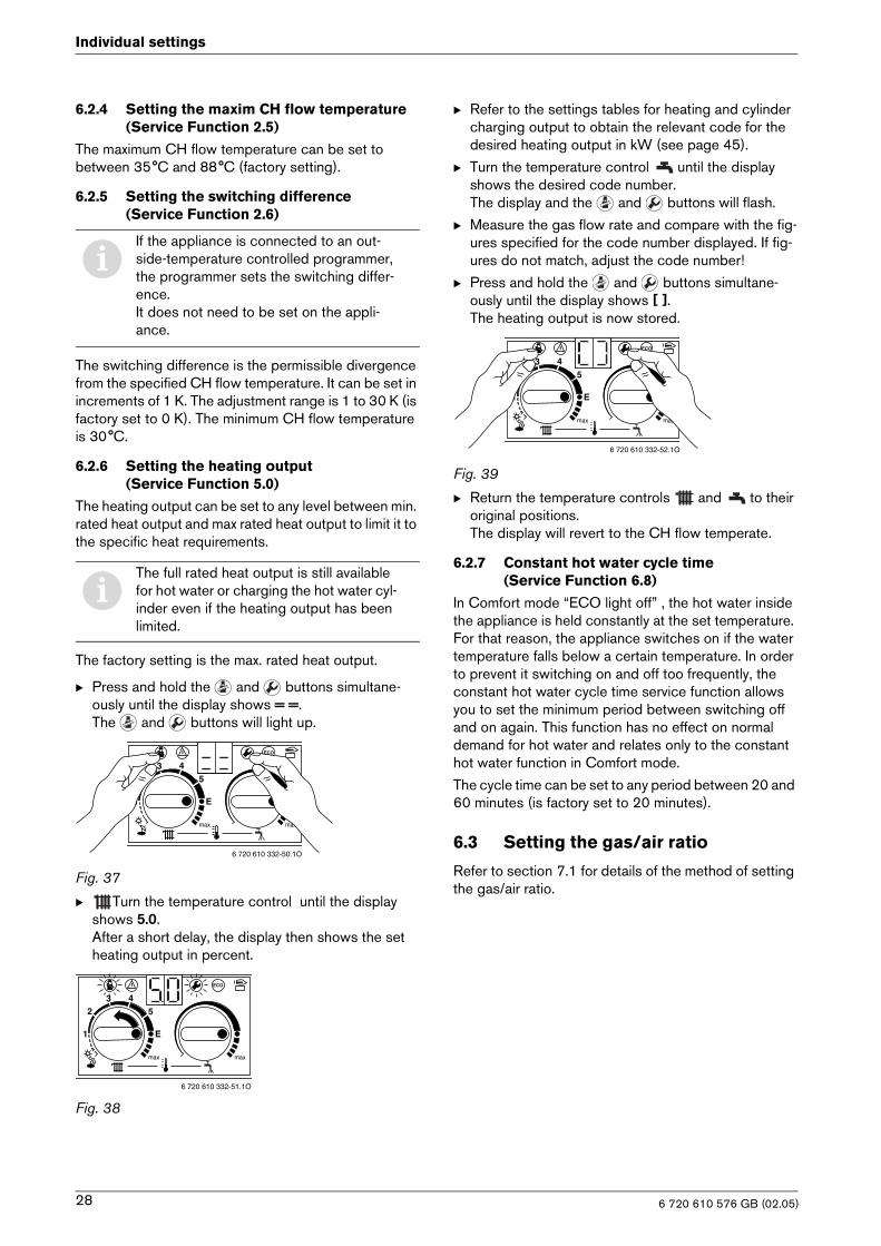
B Press and hold the and buttons simultane-ously until the display shows = =.The and buttons will light up.
Fig. 37
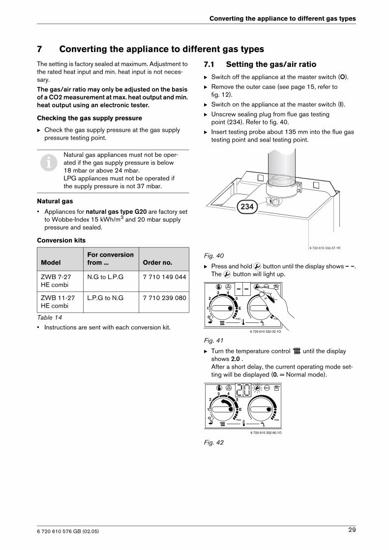
B Turn the temperature control until the display shows 5.0.After a short delay, the display then shows the set heating output in percent.
Fig. 38
B Refer to the settings tables for heating and cylinder charging output to obtain the relevant code for the desired heating output in kW (see page 45).
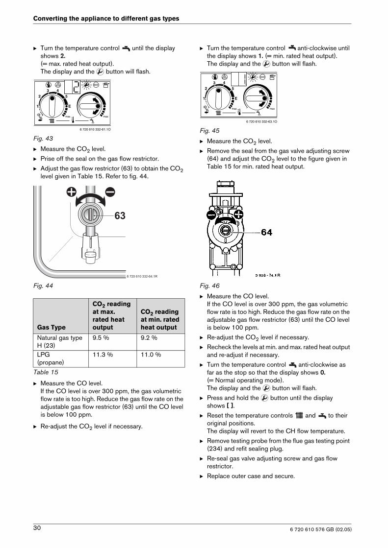
B Turn the temperature control until the display shows the desired code number.The display and the and buttons will flash.
B Measure the gas flow rate and compare with the fig-ures specified for the code number displayed. If fig-ures do not match, adjust the code number!
B Press and hold the and buttons simultane-ously until the display shows [ ].The heating output is now stored.
Fig. 39
B Return the temperature controls and to their original positions.The display will revert to the CH flow temperate.
6.2.7 Constant hot water cycle time (Service Function 6.8)
In Comfort mode “ECO light off” , the hot water inside the appliance is held constantly at the set temperature. For that reason, the appliance switches on if the water temperature falls below a certain temperature. In order to prevent it switching on and off too frequently, the constant hot water cycle time service function allows you to set the minimum period between switching off and on again. This function has no effect on normal demand for hot water and relates only to the constant hot water function in Comfort mode.
The cycle time can be set to any period between 20 and 60 minutes (is factory set to 20 minutes).
6.3 Setting the gas/air ratio
Refer to section 7.1 for details of the method of setting the gas/air ratio.
iIf the appliance is connected to an out-side-temperature controlled programmer, the programmer sets the switching differ-ence. It does not need to be set on the appli-ance.
iThe full rated heat output is still available for hot water or charging the hot water cyl-inder even if the heating output has been limited.
6 720 610 332-50.1O
6 720 610 332-51.1O
6 720 610 332-52.1O
6 720 610 576 GB (02.05)28
Converting the appliance to different gas types
7 Converting the appliance to different gas types
The setting is factory sealed at maximum. Adjustment to the rated heat input and min. heat input is not neces-sary.
The gas/air ratio may only be adjusted on the basis of a CO2 measurement at max. heat output and min. heat output using an electronic tester.
Checking the gas supply pressure
B Check the gas supply pressure at the gas supply pressure testing point.
Natural gas
• Appliances for natural gas type G20 are factory set to Wobbe-Index 15 kWh/m3 and 20 mbar supply pressure and sealed.
Conversion kits
• Instructions are sent with each conversion kit.
7.1 Setting the gas/air ratio
B Switch off the appliance at the master switch (O).
B Remove the outer case (see page 15, refer to fig. 12).
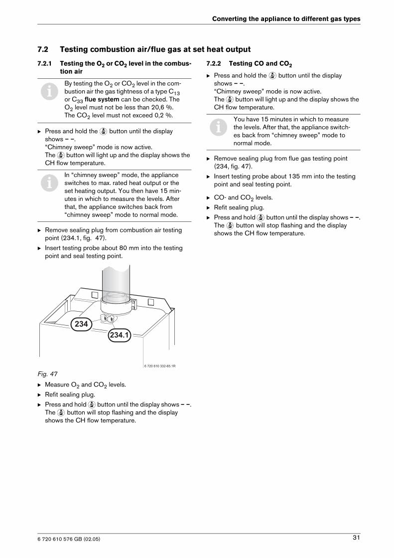
B Switch on the appliance at the master switch (I).B Unscrew sealing plug from flue gas testing
point (234). Refer to fig. 40.
B Insert testing probe about 135 mm into the flue gas testing point and seal testing point.
Fig. 40
B Press and hold button until the display shows – –.The button will light up.
Fig. 41
B Turn the temperature control until the display shows 2.0 . After a short delay, the current operating mode set-ting will be displayed (0. = Normal mode).
Fig. 42
iNatural gas appliances must not be oper-ated if the gas supply pressure is below 18 mbar or above 24 mbar.LPG appliances must not be operated if the supply pressure is not 37 mbar.
ModelFor conversion from ... Order no.
ZWB 7-27 HE combi
N.G to L.P.G 7 710 149 044
ZWB 11-27 HE combi
L.P.G to N.G 7 710 239 080
Table 14
�������������� ��
���
6 720 610 332-32.1O
6 720 610 332-60.1O
6 720 610 576 GB (02.05) 29
Converting the appliance to different gas types
B Turn the temperature control until the display shows 2. (= max. rated heat output).The display and the button will flash.
Fig. 43
B Measure the CO2 level.
B Prise off the seal on the gas flow restrictor.
B Adjust the gas flow restrictor (63) to obtain the CO2 level given in Table 15. Refer to fig. 44.
Fig. 44
B Measure the CO level.If the CO level is over 300 ppm, the gas volumetric flow rate is too high. Reduce the gas flow rate on the adjustable gas flow restrictor (63) until the CO level is below 100 ppm.
B Re-adjust the CO2 level if necessary.
B Turn the temperature control anti-clockwise until the display shows 1. (= min. rated heat output).The display and the button will flash.
Fig. 45
B Measure the CO2 level.
B Remove the seal from the gas valve adjusting screw (64) and adjust the CO2 level to the figure given in Table 15 for min. rated heat output.
Fig. 46
B Measure the CO level.If the CO level is over 300 ppm, the gas volumetric flow rate is too high. Reduce the gas flow rate on the adjustable gas flow restrictor (63) until the CO level is below 100 ppm.
B Re-adjust the CO2 level if necessary.
B Recheck the levels at min. and max. rated heat output and re-adjust if necessary.
B Turn the temperature control anti-clockwise as far as the stop so that the display shows 0. (= Normal operating mode).The display and the button will flash.
B Press and hold the button until the display shows [ ].
B Reset the temperature controls and to their original positions.The display will revert to the CH flow temperature.
B Remove testing probe from the flue gas testing point (234) and refit sealing plug.
B Re-seal gas valve adjusting screw and gas flow restrictor.
B Replace outer case and secure.
Gas Type
CO2 reading at max. rated heat output
CO2 reading at min. rated heat output
Natural gas type H (23)
9.5 % 9.2 %
LPG (propane)
11.3 % 11.0 %
Table 15
6 720 610 332-61.1O
��
�����������������
6 720 610 332-63.1O
6 720 610 576 GB (02.05)30
Converting the appliance to different gas types
7.2 Testing combustion air/flue gas at set heat output
7.2.1 Testing the O2 or CO2 level in the combus-tion air
B Press and hold the button until the display shows – –.“Chimney sweep” mode is now active. The button will light up and the display shows the CH flow temperature.
B Remove sealing plug from combustion air testing point (234.1, fig. 47).
B Insert testing probe about 80 mm into the testing point and seal testing point.
Fig. 47
B Measure O2 and CO2 levels.
B Refit sealing plug.
B Press and hold button until the display shows – –.The button will stop flashing and the display shows the CH flow temperature.
7.2.2 Testing CO and CO2
B Press and hold the button until the displayshows – –.“Chimney sweep” mode is now active.The button will light up and the display shows the CH flow temperature.
B Remove sealing plug from flue gas testing point (234, fig. 47).
B Insert testing probe about 135 mm into the testing point and seal testing point.
B CO- and CO2 levels.
B Refit sealing plug.
B Press and hold button until the display shows – –.The button will stop flashing and the display shows the CH flow temperature.
iBy testing the O2 or CO2 level in the com-bustion air the gas tightness of a type C13 or C33 flue system can be checked. The O2 level must not be less than 20,6 %. The CO2 level must not exceed 0,2 %.
iIn “chimney sweep” mode, the appliance switches to max. rated heat output or the set heating output. You then have 15 min-utes in which to measure the levels. After that, the appliance switches back from “chimney sweep” mode to normal mode.
��������������� �
���
�����
iYou have 15 minutes in which to measure the levels. After that, the appliance switch-es back from “chimney sweep” mode to normal mode.
6 720 610 576 GB (02.05) 31
Maintenance
8 Maintenance
B The User should be recommended to have the appli-ance serviced regularly by a competent person (see Maintenance Contract).
B Use only genuine spare parts
B Refer to the Spare Parts List when ordering spare parts.
B Always renew seals and O-rings removed during servicing or repair work.
B Use only the following types of grease:
– Water valve: WRc approved silicon based grease– Unions: approved sealant.
B To drain the appliance shut the system valves and open the pressure relief valve.
B Always disconnect the appliance from the electrical power supply (fuse, circuit breaker) before carrying out any work on the electrical systems or components.
B Always turn off the gas cock before car-rying out any work on components which carry gas.
iThere is a Service booklet for the Engi-neer, order no. 7 181 465 346, available to competent persons.
iAll safety and control systems are moni-tored by the Bosch Heatronic. In the event of a component fault, the display shows a fault code.
6 720 610 576 GB (02.05)32
Maintenance
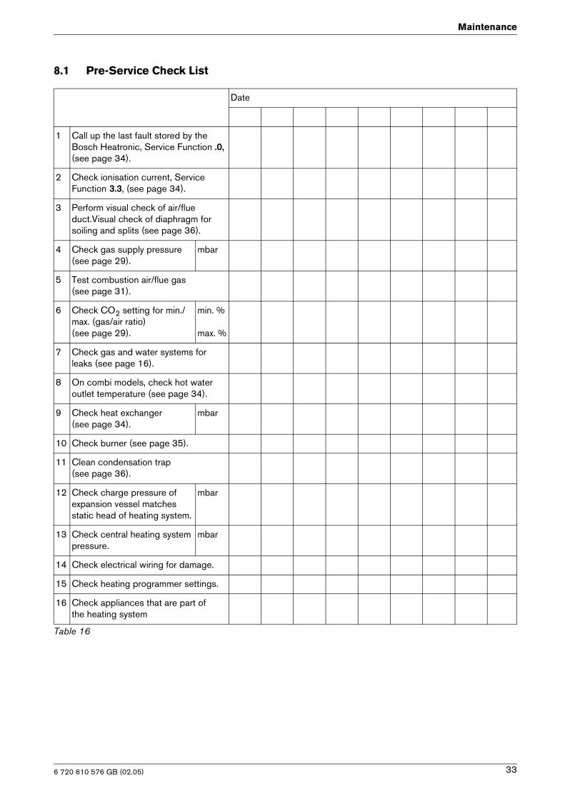
8.1 Pre-Service Check List
Date
1 Call up the last fault stored by the Bosch Heatronic, Service Function .0, (see page 34).
2 Check ionisation current, Service Function 3.3, (see page 34).
3 Perform visual check of air/flue duct.Visual check of diaphragm for soiling and splits (see page 36).
4 Check gas supply pressure (see page 29).
mbar
5 Test combustion air/flue gas(see page 31).
6 Check CO2 setting for min./max. (gas/air ratio)(see page 29).
min. %
max. %
7 Check gas and water systems for leaks (see page 16).
8 On combi models, check hot water outlet temperature (see page 34).
9 Check heat exchanger(see page 34).
mbar
10 Check burner (see page 35).
11 Clean condensation trap(see page 36).
12 Check charge pressure of expansion vessel matches static head of heating system.
mbar
13 Check central heating system pressure.
mbar
14 Check electrical wiring for damage.
15 Check heating programmer settings.
16 Check appliances that are part ofthe heating system
Table 16
6 720 610 576 GB (02.05) 33
Maintenance
8.2 Description of servicing operations
The combustion performance must be checked before and after any servicing work on the combustion and burner components. Refer to section 7.2.
Check “Last fault stored”:
B Select Service Function .0 (see page 27 “Selecting service function”).
There is a list of the fault codes in the Appendix (see page 43.
To delete “Last fault stored”:
B Turn temperature control anti-clockwise as far as the stop.
B Press and hold the button until the display shows [ ].The last fault stored has now been deleted.
Checking the ionisation current,Service Function 3.3
B Select Service Function 3.3 (see page 27 “Selecting service function”).
If the display shows 2 or 3, the ionisation current is OK. If the display shows 0 or 1, the electrode assembly (32.1, page 6) must be cleaned or replaced.
Domestic hot water
If the flow rate is too slow:
B remove the domestic hot water heat exchanger and replace,
-or-B descale with a descaling agent approved for use on
stainless steel.
B Before removing the heat exchanger shut the inlet valve and drain the hot water circuit.
B Use new seals when replacing the heat exchanger.
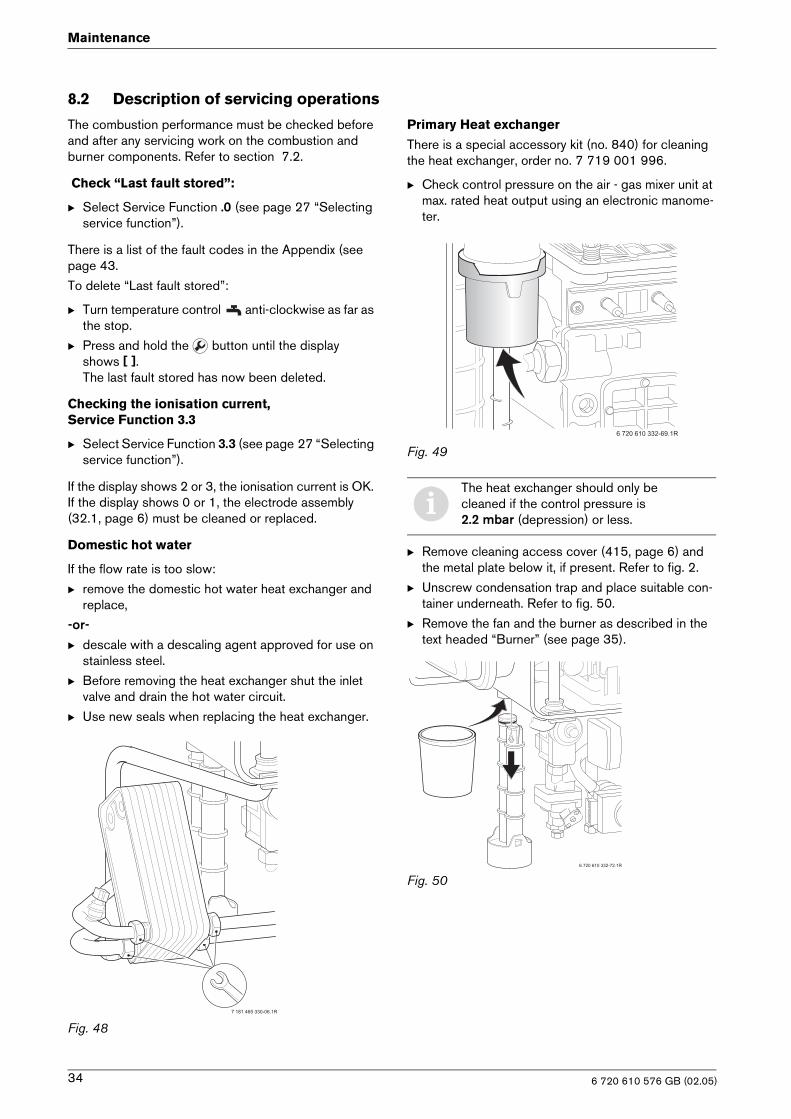
Fig. 48
Primary Heat exchanger
There is a special accessory kit (no. 840) for cleaning the heat exchanger, order no. 7 719 001 996.
B Check control pressure on the air - gas mixer unit at max. rated heat output using an electronic manome-ter.
Fig. 49
B Remove cleaning access cover (415, page 6) and the metal plate below it, if present. Refer to fig. 2.
B Unscrew condensation trap and place suitable con-tainer underneath. Refer to fig. 50.
B Remove the fan and the burner as described in the text headed “Burner” (see page 35).
Fig. 50
�������� ��������
iThe heat exchanger should only be cleaned if the control pressure is 2.2 mbar (depression) or less.
�����������������
�����������������
6 720 610 576 GB (02.05)34
Maintenance
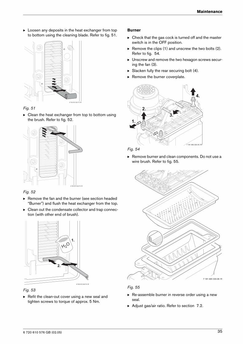
B Loosen any deposits in the heat exchanger from top to bottom using the cleaning blade. Refer to fig. 51.
Fig. 51
B Clean the heat exchanger from top to bottom using the brush. Refer to fig. 52.
Fig. 52
B Remove the fan and the burner (see section headed “Burner”) and flush the heat exchanger from the top.
B Clean out the condensate collector and trap connec-tion (with other end of brush).
Fig. 53
B Refit the clean-out cover using a new seal and tighten screws to torque of approx. 5 Nm.
Burner
B Check that the gas cock is turned off and the master switch is in the OFF position.
B Remove the clips (1) and unscrew the two bolts (2). Refer to fig. 54.
B Unscrew and remove the two hexagon screws secur-ing the fan (3).
B Slacken fully the rear securing bolt (4).
B Remove the burner coverplate.
Fig. 54
B Remove burner and clean components. Do not use a wire brush. Refer to fig. 55.
Fig. 55
B Re-assemble burner in reverse order using a new seal.
B Adjust gas/air ratio. Refer to section 7.2.
�����������������
�����������������
���
��
��
��������������� �
��
��
��
�������� ��������
��
�������� ��������
6 720 610 576 GB (02.05) 35
Maintenance
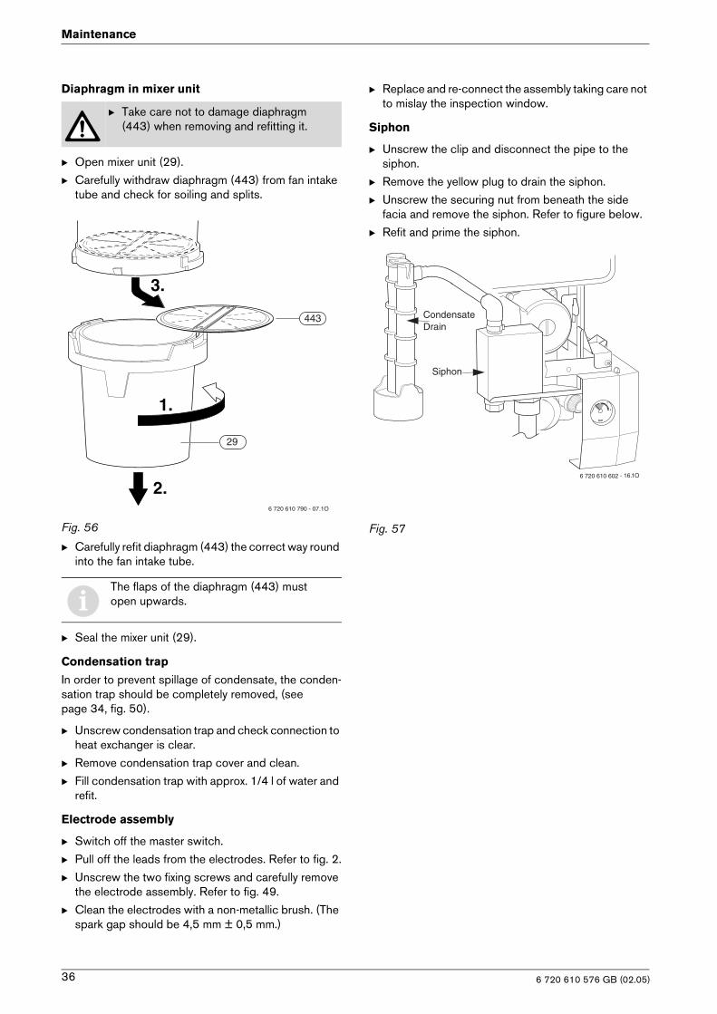
Diaphragm in mixer unit
B Open mixer unit (29).
B Carefully withdraw diaphragm (443) from fan intake tube and check for soiling and splits.
Fig. 56
B Carefully refit diaphragm (443) the correct way round into the fan intake tube.
B Seal the mixer unit (29).
Condensation trap
In order to prevent spillage of condensate, the conden-sation trap should be completely removed, (see page 34, fig. 50).
B Unscrew condensation trap and check connection to heat exchanger is clear.
B Remove condensation trap cover and clean.
B Fill condensation trap with approx. 1/4 l of water and refit.
Electrode assembly
B Switch off the master switch.
B Pull off the leads from the electrodes. Refer to fig. 2.
B Unscrew the two fixing screws and carefully remove the electrode assembly. Refer to fig. 49.
B Clean the electrodes with a non-metallic brush. (The spark gap should be 4,5 mm ± 0,5 mm.)
B Replace and re-connect the assembly taking care not to mislay the inspection window.
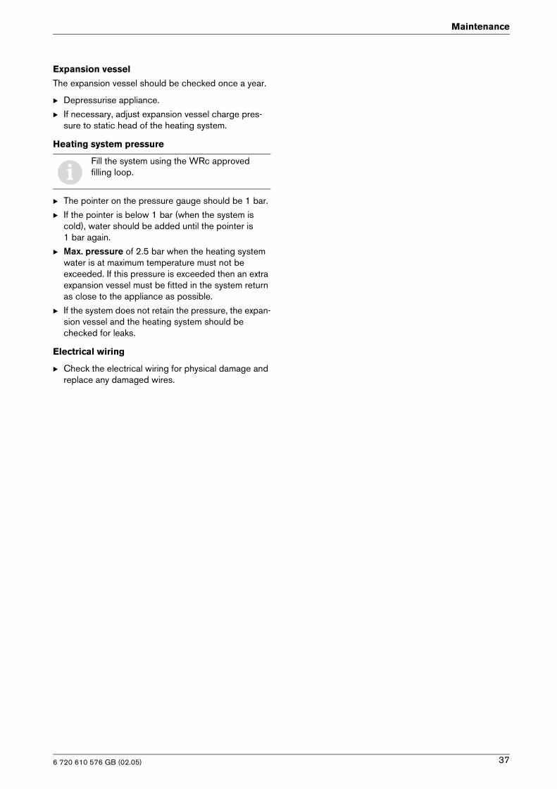
Siphon
B Unscrew the clip and disconnect the pipe to the siphon.
B Remove the yellow plug to drain the siphon.
B Unscrew the securing nut from beneath the side facia and remove the siphon. Refer to figure below.
B Refit and prime the siphon.
Fig. 57
B Take care not to damage diaphragm (443) when removing and refitting it.
iThe flaps of the diaphragm (443) must open upwards.
6 720 610 790 - 07.1O
1.
2.
29
443
3.
6 720 610 602 - 16. 1O
Siphon
CondensateDrain
6 720 610 576 GB (02.05)36
Maintenance
Expansion vessel
The expansion vessel should be checked once a year.
B Depressurise appliance.
B If necessary, adjust expansion vessel charge pres-sure to static head of the heating system.
Heating system pressure
B The pointer on the pressure gauge should be 1 bar.
B If the pointer is below 1 bar (when the system is cold), water should be added until the pointer is 1 bar again.
B Max. pressure of 2.5 bar when the heating system water is at maximum temperature must not be exceeded. If this pressure is exceeded then an extra expansion vessel must be fitted in the system return as close to the appliance as possible.
B If the system does not retain the pressure, the expan-sion vessel and the heating system should be checked for leaks.
Electrical wiring
B Check the electrical wiring for physical damage and replace any damaged wires.
iFill the system using the WRc approved filling loop.
6 720 610 576 GB (02.05) 37
Maintenance
8.3 Replacement of Parts
Before changing any components check that the gas is turned off and that the appliance is electrically isolated. When necessary close the system valves and drain the appliance.
Refitting is a reverse of the procedure for removal using new seals or o-rings as appropriate.
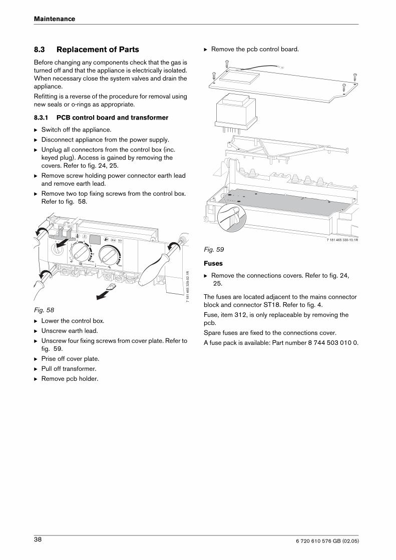
8.3.1 PCB control board and transformer
B Switch off the appliance.
B Disconnect appliance from the power supply.
B Unplug all connectors from the control box (inc. keyed plug). Access is gained by removing the covers. Refer to fig. 24, 25.
B Remove screw holding power connector earth lead and remove earth lead.
B Remove two top fixing screws from the control box. Refer to fig. 58.
Fig. 58
B Lower the control box.
B Unscrew earth lead.
B Unscrew four fixing screws from cover plate. Refer to fig. 59.
B Prise off cover plate.
B Pull off transformer.
B Remove pcb holder.
B Remove the pcb control board.
Fig. 59
Fuses
B Remove the connections covers. Refer to fig. 24, 25.
The fuses are located adjacent to the mains connector block and connector ST18. Refer to fig. 4.
Fuse, item 312, is only replaceable by removing the pcb.
Spare fuses are fixed to the connections cover.
A fuse pack is available: Part number 8 744 503 010 0.
����
��
�����
��
�
�
� �
�
�
���
�
���
�
���
�������� ��������
6 720 610 576 GB (02.05)38
Maintenance
8.3.2 Fan Assembly
Fig. 60
B Switch off the appliance.
B Disconnect the appliance from the power supply.
B Undo lower pipe union on gas pipe (1.). Refer to fig. 60.
B Remove fan lead and earth connector (2.). The earth connector has a positive clip fixing.
B Remove fixing screws attaching fan to the burner cover (3.).
B Remove fan together with gas pipe and mixer unit.
B Separate the fan from the pipe and mixer unit by twisting the mixer unit to release it (4.).
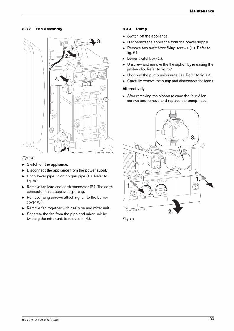
8.3.3 Pump
B Switch off the appliance.
B Disconnect the appliance from the power supply.
B Remove two switchbox fixing screws (1.). Refer to fig. 61.
B Lower switchbox (2.).
B Unscrew and remove the the siphon by releasing the jubilee clip. Refer to fig. 57.
B Unscrew the pump union nuts (3.). Refer to fig. 61.
B Carefully remove the pump and disconnect the leads.
Alternatively
B After removing the siphon release the four Allen screws and remove and replace the pump head.
Fig. 61
��
��
��
��
�������� ������ �
2.
3.
1.
1.
6 720 610 576 GB (02.05) 39
Maintenance
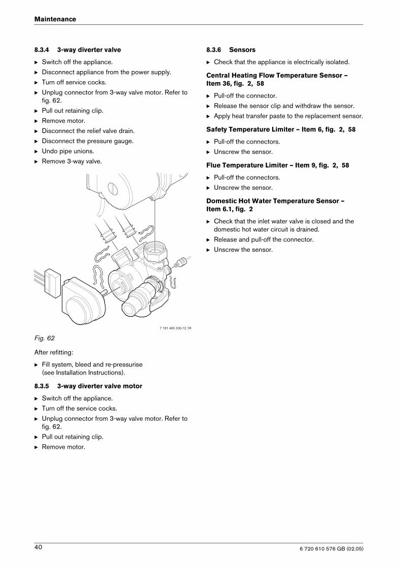
8.3.4 3-way diverter valve
B Switch off the appliance.
B Disconnect appliance from the power supply.
B Turn off service cocks.
B Unplug connector from 3-way valve motor. Refer to fig. 62.
B Pull out retaining clip.
B Remove motor.
B Disconnect the relief valve drain.
B Disconnect the pressure gauge.
B Undo pipe unions.
B Remove 3-way valve.
Fig. 62
After refitting:
B Fill system, bleed and re-pressurise(see Installation Instructions).
8.3.5 3-way diverter valve motor
B Switch off the appliance.
B Turn off the service cocks.
B Unplug connector from 3-way valve motor. Refer to fig. 62.
B Pull out retaining clip.
B Remove motor.
8.3.6 Sensors
B Check that the appliance is electrically isolated.
Central Heating Flow Temperature Sensor – Item 36, fig. 2, 58
B Pull-off the connector.
B Release the sensor clip and withdraw the sensor.
B Apply heat transfer paste to the replacement sensor.
Safety Temperature Limiter – Item 6, fig. 2, 58
B Pull-off the connectors.
B Unscrew the sensor.
Flue Temperature Limiter – Item 9, fig. 2, 58
B Pull-off the connectors.
B Unscrew the sensor.
Domestic Hot Water Temperature Sensor – Item 6.1, fig. 2
B Check that the inlet water valve is closed and the domestic hot water circuit is drained.
B Release and pull-off the connector.
B Unscrew the sensor.
�������� ��������
6 720 610 576 GB (02.05)40
Maintenance
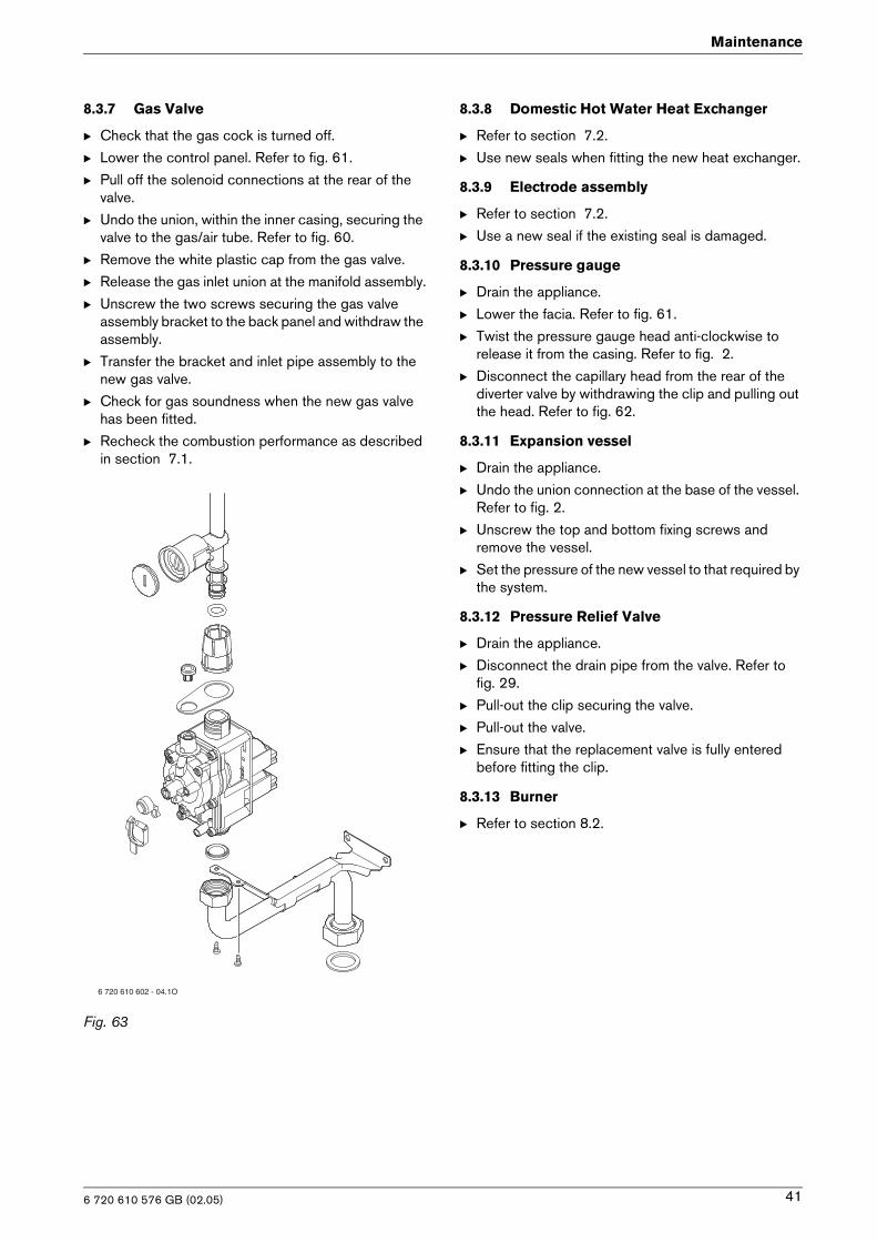
8.3.7 Gas Valve
B Check that the gas cock is turned off.
B Lower the control panel. Refer to fig. 61.
B Pull off the solenoid connections at the rear of the valve.
B Undo the union, within the inner casing, securing the valve to the gas/air tube. Refer to fig. 60.
B Remove the white plastic cap from the gas valve.
B Release the gas inlet union at the manifold assembly.
B Unscrew the two screws securing the gas valve assembly bracket to the back panel and withdraw the assembly.
B Transfer the bracket and inlet pipe assembly to the new gas valve.
B Check for gas soundness when the new gas valve has been fitted.
B Recheck the combustion performance as described in section 7.1.
Fig. 63
8.3.8 Domestic Hot Water Heat Exchanger
B Refer to section 7.2.
B Use new seals when fitting the new heat exchanger.
8.3.9 Electrode assembly
B Refer to section 7.2.
B Use a new seal if the existing seal is damaged.
8.3.10 Pressure gauge
B Drain the appliance.
B Lower the facia. Refer to fig. 61.
B Twist the pressure gauge head anti-clockwise to release it from the casing. Refer to fig. 2.
B Disconnect the capillary head from the rear of the diverter valve by withdrawing the clip and pulling out the head. Refer to fig. 62.
8.3.11 Expansion vessel
B Drain the appliance.
B Undo the union connection at the base of the vessel. Refer to fig. 2.
B Unscrew the top and bottom fixing screws and remove the vessel.
B Set the pressure of the new vessel to that required by the system.
8.3.12 Pressure Relief Valve
B Drain the appliance.
B Disconnect the drain pipe from the valve. Refer to fig. 29.
B Pull-out the clip securing the valve.
B Pull-out the valve.
B Ensure that the replacement valve is fully entered before fitting the clip.
8.3.13 Burner
B Refer to section 8.2.
6 720 610 602 - 04.1O
6 720 610 576 GB (02.05) 41
Maintenance
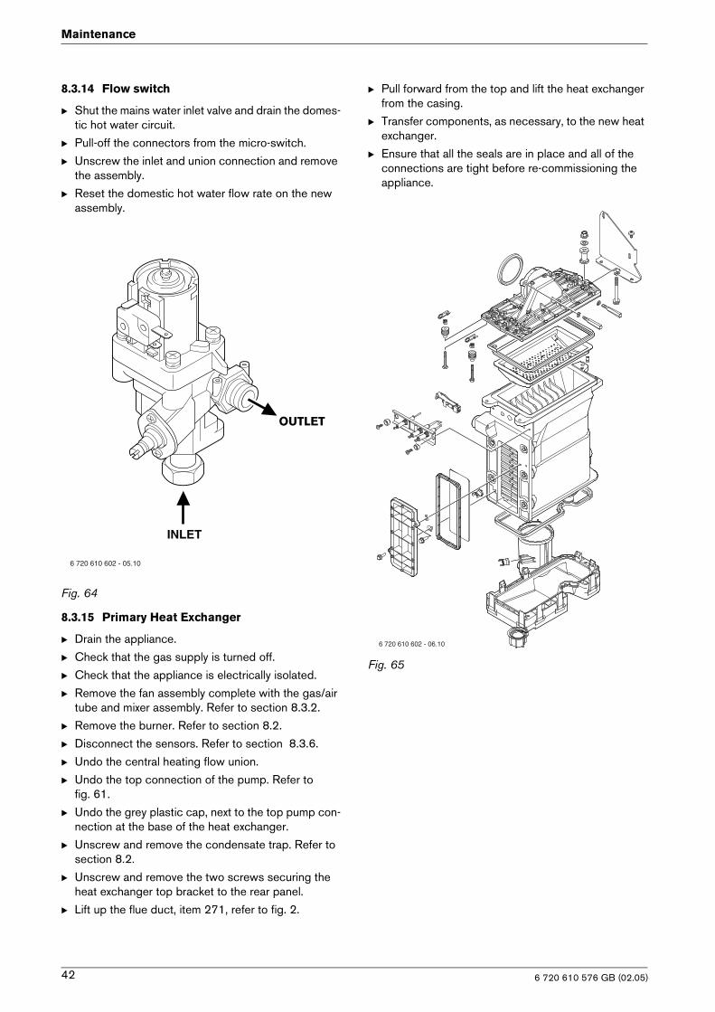
8.3.14 Flow switch
B Shut the mains water inlet valve and drain the domes-tic hot water circuit.
B Pull-off the connectors from the micro-switch.
B Unscrew the inlet and union connection and remove the assembly.
B Reset the domestic hot water flow rate on the new assembly.
Fig. 64
8.3.15 Primary Heat Exchanger
B Drain the appliance.
B Check that the gas supply is turned off.
B Check that the appliance is electrically isolated.
B Remove the fan assembly complete with the gas/air tube and mixer assembly. Refer to section 8.3.2.
B Remove the burner. Refer to section 8.2.
B Disconnect the sensors. Refer to section 8.3.6.
B Undo the central heating flow union.
B Undo the top connection of the pump. Refer to fig. 61.
B Undo the grey plastic cap, next to the top pump con-nection at the base of the heat exchanger.
B Unscrew and remove the condensate trap. Refer to section 8.2.
B Unscrew and remove the two screws securing the heat exchanger top bracket to the rear panel.
B Lift up the flue duct, item 271, refer to fig. 2.
B Pull forward from the top and lift the heat exchanger from the casing.
B Transfer components, as necessary, to the new heat exchanger.
B Ensure that all the seals are in place and all of the connections are tight before re-commissioning the appliance.
Fig. 65
6 720 610 602 - 05.10
INLET
OUTLET
6 720 610 602 - 06.10
6 720 610 576 GB (02.05)42
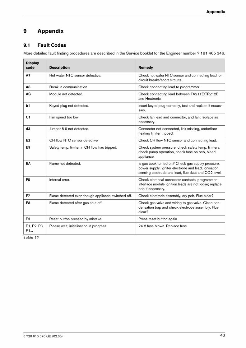
Appendix
9 Appendix
9.1 Fault Codes
More detailed fault finding procedures are described in the Service booklet for the Engineer number 7 181 465 346.
Display code Description Remedy
A7 Hot water NTC sensor defective. Check hot water NTC sensor and connecting lead for circuit breaks/short circuits.
A8 Break in communication Check connecting lead to programmer
AC Module not detected. Check connecting lead between TA211E/TR212E and Heatronic
b1 Keyed plug not detected. Insert keyed plug correctly, test and replace if neces-sary.
C1 Fan speed too low. Check fan lead and connector, and fan; replace as necessary.
d3 Jumper 8-9 not detected. Connector not connected, link missing, underfloor heating limiter tripped.
E2 CH flow NTC sensor defective Check CH flow NTC sensor and connecting lead.
E9 Safety temp. limiter in CH flow has tripped. Check system pressure, check safety temp. limiters, check pump operation, check fuse on pcb, bleed appliance.
EA Flame not detected. Is gas cock turned on? Check gas supply pressure, power supply, igniter electrode and lead, ionisation sensing electrode and lead, flue duct and CO2 level.
F0 Internal error. Check electrical connector contacts, programmer interface module ignition leads are not loose; replace pcb if necessary.
F7 Flame detected even though appliance switched off. Check electrode assembly, dry pcb. Flue clear?
FA Flame detected after gas shut off. Check gas valve and wiring to gas valve. Clean con-densation trap and check electrode assembly. Flue clear?
Fd Reset button pressed by mistake. Press reset button again
P1, P2, P3, P1...
Please wait, initialisation in progress. 24 V fuse blown. Replace fuse.
Table 17
6 720 610 576 GB (02.05) 43
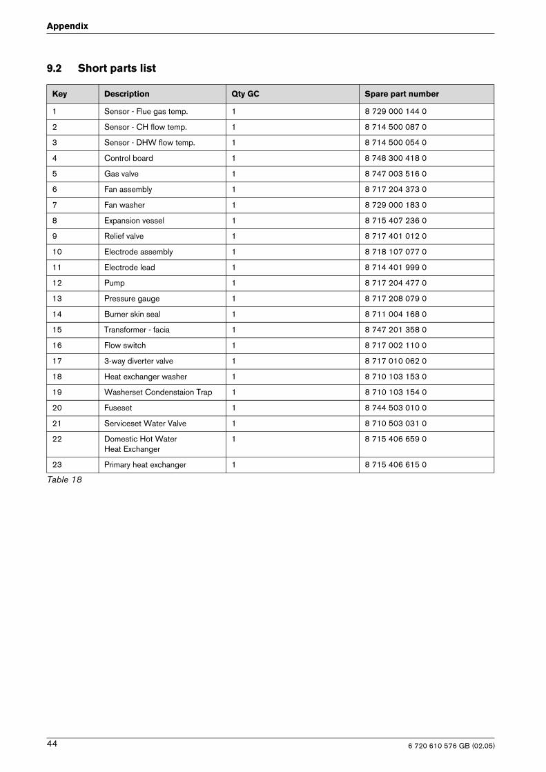
Appendix
9.2 Short parts list
Key Description Qty GC Spare part number
1 Sensor - Flue gas temp. 1 8 729 000 144 0
2 Sensor - CH flow temp. 1 8 714 500 087 0
3 Sensor - DHW flow temp. 1 8 714 500 054 0
4 Control board 1 8 748 300 418 0
5 Gas valve 1 8 747 003 516 0
6 Fan assembly 1 8 717 204 373 0
7 Fan washer 1 8 729 000 183 0
8 Expansion vessel 1 8 715 407 236 0
9 Relief valve 1 8 717 401 012 0
10 Electrode assembly 1 8 718 107 077 0
11 Electrode lead 1 8 714 401 999 0
12 Pump 1 8 717 204 477 0
13 Pressure gauge 1 8 717 208 079 0
14 Burner skin seal 1 8 711 004 168 0
15 Transformer - facia 1 8 747 201 358 0
16 Flow switch 1 8 717 002 110 0
17 3-way diverter valve 1 8 717 010 062 0
18 Heat exchanger washer 1 8 710 103 153 0
19 Washerset Condenstaion Trap 1 8 710 103 154 0
20 Fuseset 1 8 744 503 010 0
21 Serviceset Water Valve 1 8 710 503 031 0
22 Domestic Hot Water Heat Exchanger
1 8 715 406 659 0
23 Primary heat exchanger 1 8 715 406 615 0
Table 18
6 720 610 576 GB (02.05)44
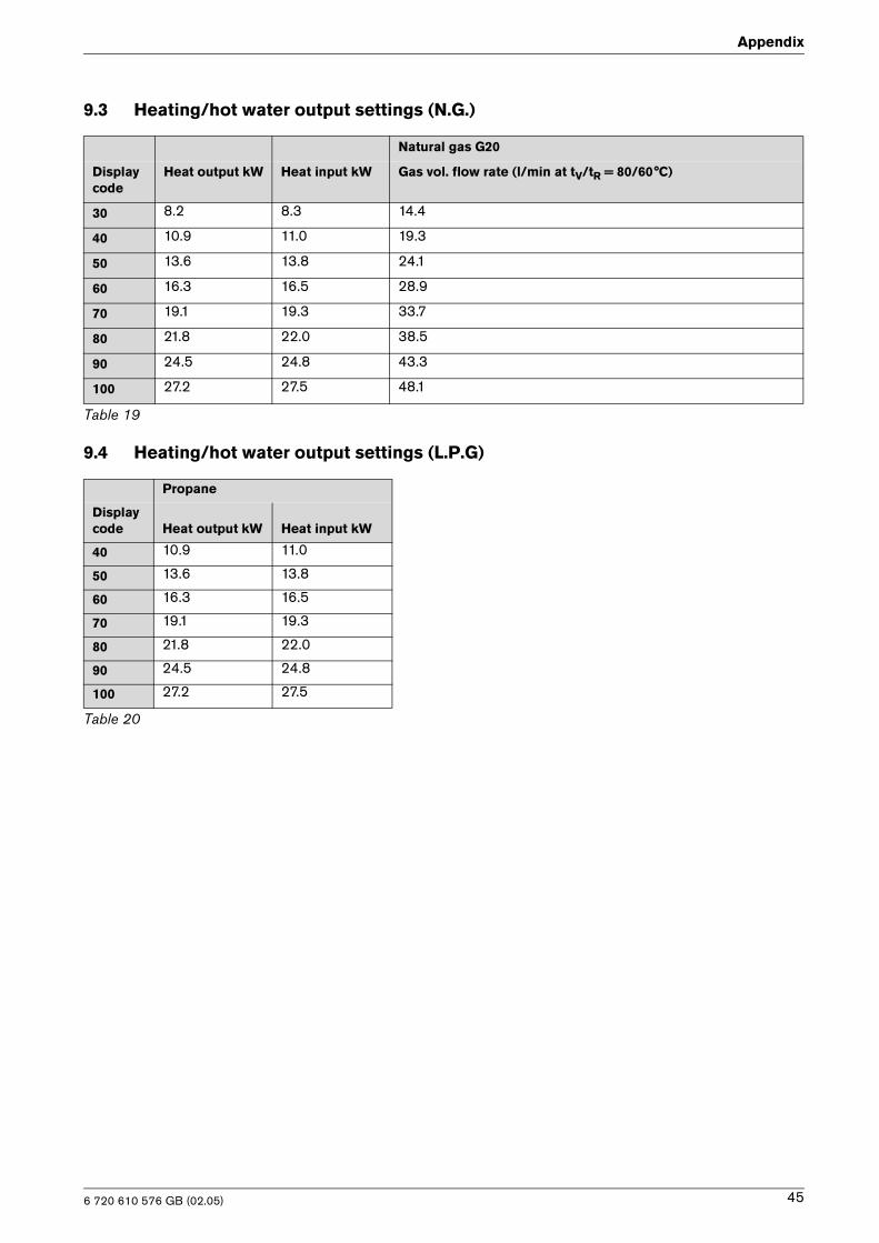
Appendix
9.3 Heating/hot water output settings (N.G.)
9.4 Heating/hot water output settings (L.P.G)
Natural gas G20
Display code
Heat output kW Heat input kW Gas vol. flow rate (l/min at tV/tR = 80/60°C)
30 8.2 8.3 14.4
40 10.9 11.0 19.3
50 13.6 13.8 24.1
60 16.3 16.5 28.9
70 19.1 19.3 33.7
80 21.8 22.0 38.5
90 24.5 24.8 43.3
100 27.2 27.5 48.1
Table 19
Propane
Display code Heat output kW Heat input kW
40 10.9 11.0
50 13.6 13.8
60 16.3 16.5
70 19.1 19.3
80 21.8 22.0
90 24.5 24.8
100 27.2 27.5
Table 20
6 720 610 576 GB (02.05) 45
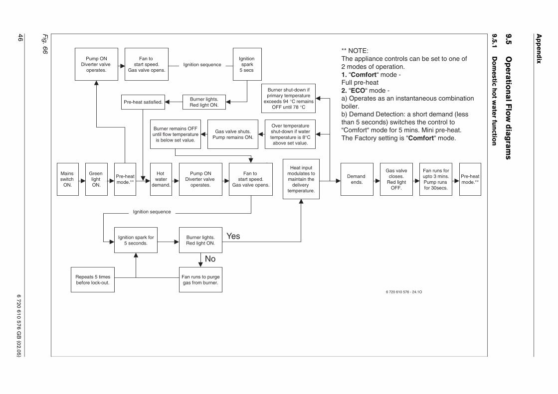
6 720 610 576 GB
(02.05)46 A
pp
end
ix
9.5O
peratio
na
l Flo
w d
iagram
s
9.5.1D
om
estic ho
t wa
ter fu
nctio
n
Fig
Gas valvecloses.
Red lightOFF.
Fan runs forupto 3 mins.Pump runs for 30secs.
:liance controls can be set to one of
s of operation.fort“ mode -
-heat“ mode -ates as an instantaneous combination
and Detection: a short demand (lesseconds) switches the control tort“ mode for 5 mins. Mini pre-heat.tory setting is “Comfort“ mode.
Pre-heatmode.**
6 720 610 576 - 24.1O
. 66
Mains switch
ON.
Green light ON.
Burner lights.Red light ON.
Ignition spark for5 seconds.
Fan runs to purgegas from burner.
Repeats 5 timesbefore lock-out.
Hot water
demand.
Pump ONDiverter valve
operates.
Heat inputmodulates tomaintain the
delivery temperature.
Over temperatureshut-down if watertemperature is 8°Cabove set value.
Burner remains OFFuntil flow temperature
is below set value.
Gas valve shuts.Pump remains ON.
Demandends.
Yes
No
** NOTEThe app2 mode1. “ComFull pre2. “ECOa) Operboiler.b) Demthan 5 s“ComfoThe Fac
Fan to start speed.
Gas valve opens.
Pre-heatmode.**
Ignition sequence
Burner shut-down ifprimary temperature
exceeds 94 °C remainsOFF until 78 °C
Pump ONDiverter valve
operates.
Fan to start speed.
Gas valve opens.
Pre-heat satisfied.
Ignition sequence
Burner lights.Red light ON.
Ignition spark
5 secs
.
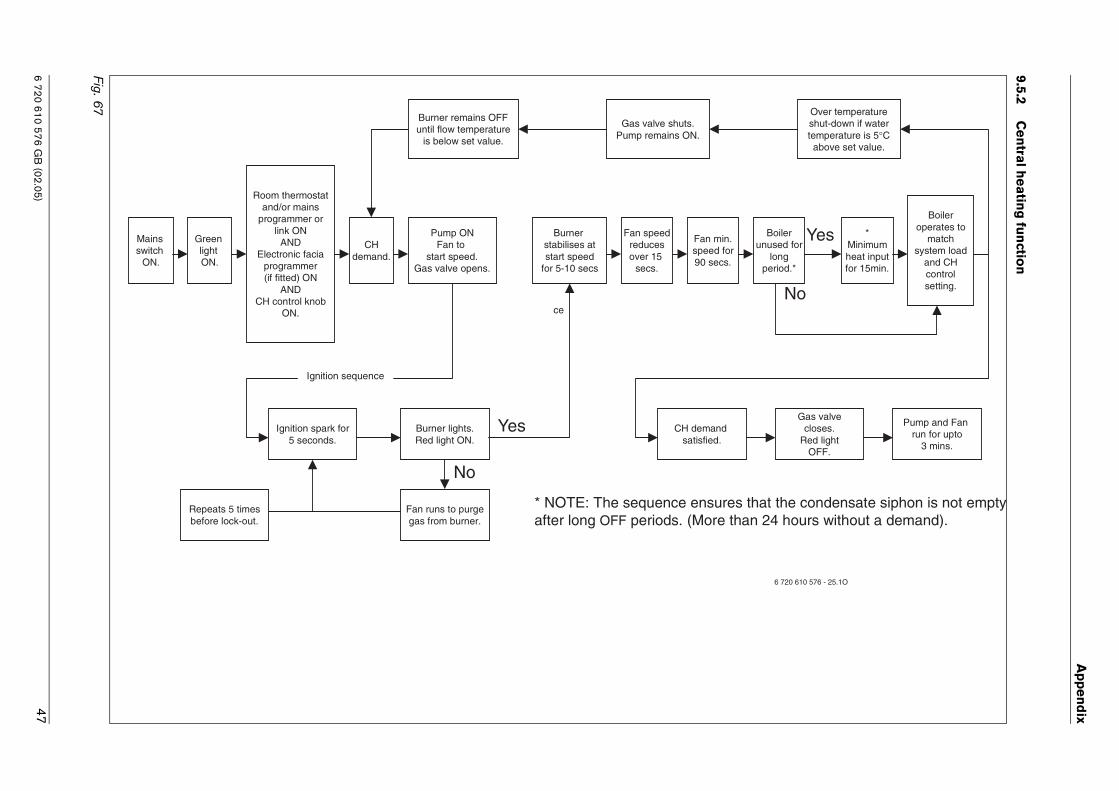
6 720 610 576 GB
(02.05)
Ap
pe
nd
ix
47
9.5.2C
en
tral he
ating
fun
ction
F
Gas valvecloses.
Red lightOFF.
*Minimumheat inputfor 15min.
Boileroperates to
matchsystem load
and CHcontrolsetting.
Boilerunused for
longperiod.*
Over temperatureshut-down if watertemperature is 5°Cabove set value.
Pump and Fan run for upto
3 mins.
Yes
No
that the condensate siphon is not emptyan 24 hours without a demand).
6 720 610 576 - 25.1O
ig. 67
Mains switch
ON.
Fan min.speed for90 secs.
Green light ON.
Burner lights.Red light ON.
Ignition spark for5 seconds.
Fan runs to purgegas from burner.
Repeats 5 timesbefore lock-out.
Room thermostatand/or mains
programmer orlink ON
ANDElectronic facia
programmer(if fitted) ON
ANDCH control knob
ON.
CHdemand.
Pump ONFan to
start speed.Gas valve opens.
Burner stabilises atstart speed
for 5-10 secs
Fan speedreducesover 15
secs.
Burner remains OFFuntil flow temperature
is below set value.
Gas valve shuts.Pump remains ON.
CH demand satisfied.
Yes
No
* NOTE: The sequence ensuresafter long OFF periods. (More th
Ignition sequence
ce

AppendixAppendix
EXCELLENCE COMES AS STANDARD
Worcester Heat Systems Limited, Cotswold Way, Warndon, Worcester WR4 9SW.Telephone: (01905) 754624 Fax: (01905) 754619