Embed Size (px)
Citation preview

EuroGeo4 Paper number 226
1
INSTALLATION AND ULTRAVIOLET EXPOSURE DAMAGE OF GEOTEXTILES Benjamim, C.V.S1, Bueno, B.S.2 Lodi, P.C3. & Zornberg, J.G.4 1 OBER S.A. Indústria e Comércio, São Paulo/SP, Brazil (e-mail: [email protected]) 2 Geotechnical Department, University of São Paulo (USP), São Carlos/SP, Brazil (e-mail: [email protected]) 3 Civil Engineering Department, São Paulo State University (UNESP), Ilha Solteira/SP, Brazil 4 Civil Engineering Department-GEO, University of Texas, Austin, Texas, USA (e-mail: [email protected])
Abstract: A better understanding on the behavior of geotextile-reinforced soil structures could be gained by
systematic monitoring of full-scale structures, combined with a thorough material characterization program. Accordingly, eight prototype geotextile-reinforced soil structures were built as part of a comprehensive study aimed at analyzing their behavior. After a through behavior evaluation of prototypes 1 and 8, reinforced with nonwoven (PET) and woven (PP) geotextiles, respectively, specimens subjected to UV exposure and installation damage were retrieved. Tensile tests were conducted in both geotextiles, using three different types of specimens: virgin samples, specimens retrieved after field placement (to characterize construction damage), and specimens subjected to UV exposure. A medium to fine sand was used to construct the reinforced backfill. The results showed that the nonwoven geotextiles presented a better installation damage behavior than the woven geotextile. The damage caused by the UV exposure was more significant to the nonwoven geotextiles (PET) than the woven geotextiles (PP), especially due to the polymer used in their manufacture process.
Keywords: geotextile, reinforced soil wall, field monitoring, laboratory test, installation damage, weathering.
INTRODUCTION The geosynthetics may suffer mechanical changes during the construction phase due to installation and compaction
damages or to chemical and biological attacks, not only from the soil but also from the underground water. Those damages can also occur in a long term due to the material creep and exposure to the ultraviolet rays (UV). An appropriate combination of these factors must be considered when it is made the selection of the geosynthetic properties for a safe project.
When a geosynthetic is used in a reinforced soil retaining wall, it makes necessary that its properties be guaranteed for a minimum time specified in project, taken into account all the factors that could in anyhow change its properties. An estimative of the durability of any application using geotextiles requires a study of the effects that construction and post-construction could affect in the functional properties of the geosynthetics. Among these factors, it can be listed the textile and polymeric structure of the product, manufacture process, chemical and physical environment that the material is applied, storage place, installation procedures and the different solicitations that the geosynthetic will suffer during its lifetime.
This paper presents the results of installation damages caused during the installation of woven and nonwoven geotextiles, as well the damages caused by the exposure to environment (exaggerated exposure to UV), in two different soil reinforced retaining wall prototypes, 4.0 m high each, reinforced with propylene (PP) woven geotextile and polyester (PET) nonwoven geotextile.
LITERATURE REVIEW
The polymers present photodegradative sensitivity differentiated to several wave lengths (λ) of UV rays. These variations of sensitivity are due to the differences in the molecular structures and chemical compositions. Region UV can be subdivided in three bands of wave lengths: UV-A (315-400 nm), UV-B (290-315 nm) and UV-C (below of 290 nm). Some references divide the bands UV-A and UV-B in 280 nm. Band UV-C does not reach the earth surface and band UV-B is the main responsible for the photochemistry changes in polymers. The maximum sensitivity of some polymers, determined for the energies of dissociation of its chemical bonds, is positioned inside the region of radiation UV with wave lengths between 290 and 400 nm. The Polypropylene (PP) presents value of λ in the 295-345 band nm while Polyester (PET) presents λ in the 330-360 band nm (AGNELLI 2002).
The degradation with time of exposed specimens is mainly initiated by the ultraviolet rays (UV) of the solar radiation, heat and oxygen, besides other climatic factors as humidity, rain, nitrogen oxides, ozone and deposits of polluted air. The atmospheric pollution and acid rains also can speed up the degradation for UV (ROLLIN 2004).
Some authors have shown that the PP presents smaller strength to UV than PET. Agnelli (2002) says that the pure PP presents low strength to environment while PET presents medium strength. Moreover, in the process of polymerization of the PP, the inclusion of starters is necessary to make the propylene reacts with another propylene in order to generate the polypropylene. These starters are cromophores and will remain in final polymer. These cromophores are absorbers of UV that becomes the PP more susceptible to UV when exposed. About PET, this susceptibility does not occur since the polymerization happens without the presence of these starters, because it is a reaction of an acid with an alcohol resulting in an ester.
Generally, the energy of the ultraviolet radiation is enough to initiate the failure of the polymer bonds, leading to a subsequent recombination as, for example, with the oxygen of air, or initiating more complex reactions in chain.
Benjamim, C.V.S., Bueno, B.S., Lodi, P.C., and Zornberg, J.G. (2008). “Installation and Ultraviolet Exposure Damage of Geotextiles.” Fourth European Geosynthetics Conference, EuroGeo4, Edinburgh, United Kingdom, 8-10 September, pp. 1-8 (CD-ROM).

EuroGeo4 Paper number 226
2
However, in the majority of the situations, the geotextile is exposed to the ultraviolet rays for a limited time during storage, transportation and installation, and right after that it is protected by a soil layer or some facing system.
The compaction can also cause damages to the reinforcement elements (mechanical damages). Besides compaction, these damages also can occur in the storage, transportation and handling of the geosynthetics. The mechanical damage is larger for coarse grain size distribution soils, small thickness of soil layers, intense mechanization of soil movement and larger compaction energies.
MATERIALS AND METHODS
Construction method
In order to improve the knowledge on the geotextile-reinforced soil retaining walls, it was constructed and instrumented 8 retaining walls, 4.0 m high each, and reinforced with woven (PP) and nonwoven (PET) geotextiles. Because the experimental character, the structures constructed in this research didn’t have any facing system protection, being exposed to evaluate the UV degradation. After the behavior evaluation of the prototypes 1 and 8, geotextile specimens were retrieved within the backfill soil, in order to evaluate the mechanical damages, as well as specimens of the facing that had been exposed for evaluation of the UV (Figures 1a and 1b).
The geotextiles were perfectly positioned over the backfill surface in order to be submitted to initial uniform state of stresses. Above the geotextile, the soil was spread with final average layer thickness of approximately 20 cm. After that, the soil was compacted using a vibratory plate, with plate dimensions of 520 mm (width) x 350 mm (length), 62 kg of mass, vibratory frequency equal to 97 Hz and maximum centrifugal force equal to 11 kN.
a) b)
Figure 1. Front view of the prototypes: a) nonwoven geotextile (PET) and b) woven geotextile (PP). Soil properties
Three different soils were used in this research, among them, two with cohesive behavior and one with granular behavior. The soil used in the construction of prototypes 1 and 8 was a poorly graded sand (Figure 2).
The maximum and minimum void ratios, emax and emin, according to ASTM D 4253 and ASTM D 4254, were 0.70 and 0.46. The backfill soil was compacted to a target relative density of 80%, which corresponds to a void ratio of 0.51 and a dry unit weight of 1.77 kN/m3. The backfill was placed in the field at a moisture content of approximately 5.0%.
The shear strength of the soil was obtained from consolidated-drained (CD) triaxial tests on specimens prepared at the unit weight and water content used during construction of the prototype wall. The shear strength is characterized by a cohesive intercept of 16 kPa and a friction angle of 33o.

EuroGeo4 Paper number 226
3
Figure 2. Grain size distribution.
Geotextile properties
It was used, in the prototypes 1 and 8, respectively, a short-fiber needle-punched polyester nonwoven geotextile, and a woven geotextile manufactured from polypropylene fibers. Tables 1 and 2 present the results of the mass per unit area and thickness tests, respectively, of the geotextiles.
Table 1. Mass per unit area tests results.
geotextile type (g/m2) cv (%) woven (PP) 204.4 1.20
nonwoven (PET) 166.3 5.15 Table 2. Thickness tests results.
geotextile type (mm) cv (%) woven (PP) 1.26 9.51
nonwoven (PET) 2.66 4.21 Damage evaluation properties
Tensile tests (ASTM D 4595) were conducted in both geotextiles using three types of geotextile specimen: virgin samples, specimens retrieved after field placement (to characterize construction damage), and specimens subjected to UV exposure (approximately 200 days for nonwoven geotextile and 1000 days for the woven geotextile).
RESULTS
Figures 3, 4, 5 and 6 present the curves load x strain of all the tests, simultaneously with the average values obtained for each type of damaged sample. Tables 3, 4, 5 and 6 present the results obtained for the geotextiles (ultimate tensile strength, strain at the failure and coefficients of variation).

EuroGeo4 Paper number 226
4
virgin samples mechanical damage UV exposure
Strain (%)
Load
(kN
/m)
5
4
3
2
1
0
0 25 50 75 100
Figure 3. Tensile strength tests conducted in the machine direction (MD) with the nonwoven geotextile: a) virgin samples, b) mechanical damaged samples, c) UV exposed samples d) comparison between the medium results of each tests.
0 25 50 75 100
10
8
6
4
2
0
virgin samples mechanical damage UV exposure
Strain (%)
Load
(kN
/m)
Figure 4. Tensile strength tests conducted in the cross machine direction (CMD) with the nonwoven geotextile: a) virgin samples, b) mechanical damaged samples, c) UV exposed samples d) comparison between the medium results of each tests.
b)
c)
d)
a)
b)
c)
d)
a)

EuroGeo4 Paper number 226
5
0 10 20 30 40
60
48
36
24
12
0
virgin samples mechanical damage UV exposure
Strain (%)
Load
(kN
/m)
Figure 5. Tensile strength tests conducted in the machine direction (MD) with the woven geotextile: a) virgin samples, b) mechanical damaged samples, c) UV exposed samples d) comparison between the medium results of each tests.
0 10 20 30 40
15
12
9
6
3
0
virgin samples mechanical damage UV exposure
Strain (%)
Load
(kN
/m)
Figure 6. Tensile strength tests conducted in the cross machine direction (CMD) with the woven geotextile: a) virgin samples, b) mechanical damaged samples, c) UV exposed samples d) comparison between the medium results of each tests.
a)
b)
c)
d)
a)
b)
c)
d)
EuroGeo4 Paper number 226
6
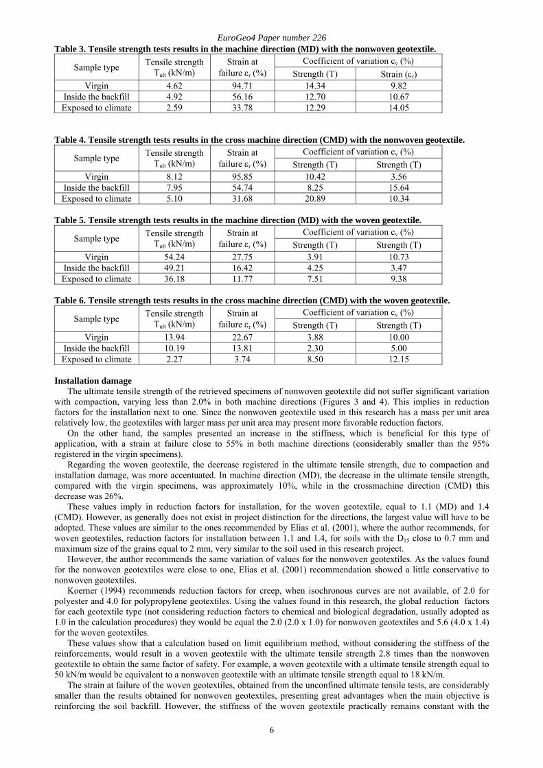
Table 3. Tensile strength tests results in the machine direction (MD) with the nonwoven geotextile.
Sample type Tensile strength Tult (kN/m)
Strain at failure εr (%)
Coefficient of variation cv (%) Strength (T) Strain (εr)
Virgin 4.62 94.71 14.34 9.82 Inside the backfill 4.92 56.16 12.70 10.67 Exposed to climate 2.59 33.78 12.29 14.05
Table 4. Tensile strength tests results in the cross machine direction (CMD) with the nonwoven geotextile.
Sample type Tensile strength Tult (kN/m)
Strain at failure εr (%)
Coefficient of variation cv (%) Strength (T) Strength (T)
Virgin 8.12 95.85 10.42 3.56 Inside the backfill 7.95 54.74 8.25 15.64 Exposed to climate 5.10 31.68 20.89 10.34
Table 5. Tensile strength tests results in the machine direction (MD) with the woven geotextile.
Sample type Tensile strength Tult (kN/m)
Strain at failure εr (%)
Coefficient of variation cv (%) Strength (T) Strength (T)
Virgin 54.24 27.75 3.91 10.73 Inside the backfill 49.21 16.42 4.25 3.47 Exposed to climate 36.18 11.77 7.51 9.38
Table 6. Tensile strength tests results in the cross machine direction (CMD) with the woven geotextile.
Sample type Tensile strength Tult (kN/m)
Strain at failure εr (%)
Coefficient of variation cv (%) Strength (T) Strength (T)
Virgin 13.94 22.67 3.88 10.00 Inside the backfill 10.19 13.81 2.30 5.00 Exposed to climate 2.27 3.74 8.50 12.15
Installation damage
The ultimate tensile strength of the retrieved specimens of nonwoven geotextile did not suffer significant variation with compaction, varying less than 2.0% in both machine directions (Figures 3 and 4). This implies in reduction factors for the installation next to one. Since the nonwoven geotextile used in this research has a mass per unit area relatively low, the geotextiles with larger mass per unit area may present more favorable reduction factors.
On the other hand, the samples presented an increase in the stiffness, which is beneficial for this type of application, with a strain at failure close to 55% in both machine directions (considerably smaller than the 95% registered in the virgin specimens).
Regarding the woven geotextile, the decrease registered in the ultimate tensile strength, due to compaction and installation damage, was more accentuated. In machine direction (MD), the decrease in the ultimate tensile strength, compared with the virgin specimens, was approximately 10%, while in the crossmachine direction (CMD) this decrease was 26%.
These values imply in reduction factors for installation, for the woven geotextile, equal to 1.1 (MD) and 1.4 (CMD). However, as generally does not exist in project distinction for the directions, the largest value will have to be adopted. These values are similar to the ones recommended by Elias et al. (2001), where the author recommends, for woven geotextiles, reduction factors for installation between 1.1 and 1.4, for soils with the D15 close to 0.7 mm and maximum size of the grains equal to 2 mm, very similar to the soil used in this research project.
However, the author recommends the same variation of values for the nonwoven geotextiles. As the values found for the nonwoven geotextiles were close to one, Elias et al. (2001) recommendation showed a little conservative to nonwoven geotextiles.
Koerner (1994) recommends reduction factors for creep, when isochronous curves are not available, of 2.0 for polyester and 4.0 for polypropylene geotextiles. Using the values found in this research, the global reduction factors for each geotextile type (not considering reduction factors to chemical and biological degradation, usually adopted as 1.0 in the calculation procedures) they would be equal the 2.0 (2.0 x 1.0) for nonwoven geotextiles and 5.6 (4.0 x 1.4) for the woven geotextiles.
These values show that a calculation based on limit equilibrium method, without considering the stiffness of the reinforcements, would result in a woven geotextile with the ultimate tensile strength 2.8 times than the nonwoven geotextile to obtain the same factor of safety. For example, a woven geotextile with a ultimate tensile strength equal to 50 kN/m would be equivalent to a nonwoven geotextile with an ultimate tensile strength equal to 18 kN/m.
The strain at failure of the woven geotextiles, obtained from the unconfined ultimate tensile tests, are considerably smaller than the results obtained for nonwoven geotextiles, presenting great advantages when the main objective is reinforcing the soil backfill. However, the stiffness of the woven geotextile practically remains constant with the

EuroGeo4 Paper number 226
7
confinement effect, while the nonwoven geotextile presents considerably increments of the stiffness when confined in the soil. Some authors as Kamiji (2006) and Gomes (1992) found values for the confined stiffness modulus for nonwoven geotextiles up to five times larger than the modulus obtained from unconfined tests. Additionally, secondary factors can contribute for a better behavior of these type of structure reinforced with nonwoven geotextiles, as the control of the backfill drainage and suction of the soil.
The good performance of nonwoven geotextile-reinforced soil retaining walls have been showed in the literature, as Ehrlich et al. (1997). The authors constructed two different walls, 10 m high each, reinforced with two different types of geotextiles (woven and nonwoven). The results showed that the structure reinforced with nonwoven geotextiles presented smaller displacements than the one reinforced with woven geotextile.
Similar results were obtained in this research, where the results of both prototypes 1 and 8 were very similar. The largest strains registered in the prototype 1, reinforced with nonwoven geotextiles, were equal to 0.6% at the end of the construction, localized at level 2.0 m. The other layers presented strains equal to 0.4, 0.2, 0.5 and 0.0, at levels 0.4, 1.2, 2.8 and 3.6 m, respectively. The prototype 8, reinforced with woven geotextile, also presented the largest strain equal to 0.6%, at level 1.2 m. The other layers registered strains equal to 0.0, 0.3, 0.4 and 0.5, at levels 0.4, 2.0, 2.8 and 3.6 m, respectively
However, this behavior can’t be totally explained, mainly when compared with the results of structures reinforced with less inextensible reinforcements, as woven geotextiles and geogrids. The results presented in this paper can contribute for one a better understanding of the nonwoven geotextiles when applied as reinforcement elements in retaining walls. UV exposure damage
Regarding the damages caused by the exposition to UV, a comparative analysis of the results becomes difficult, since the woven geotextile specimens were exposed for a period five times larger than the nonwoven geotextile specimens. Besides that, the position that the prototypes were exposed to the sun was different during most of the year. The results showed that the woven geotextiles (PP) presented a similar performance to the nonwoven geotextiles (PET), for the machine direction. However, the results showed a great discrepancy to the results obtained for the crossmachine direction specimens.
The nonwoven geotextiles, manufactured with PET fibers, presented a reduction in the ultimate tensile load equal to 44% in MD and 38% in CMD, after an exposition of approximately 200 days. The stiffness modulus presented and increase of 60% in MD and 90% in CMD. The woven geotextile, manufactured with PP, presented a high discrepancy comparing the two machine directions. In the MD, the reduction in the ultimate tensile load was, after approximately 1000 days, 33%, while in the CMD, the reduction was 84%. A small increase in the stiffness modulus on the exposed specimens, when compared with virgin specimens, was verified, reaching 37% in MD and 21% in CMD. when compared with the virgin samples.
SUMMARY AND CONCLUSIONS
This paper presented the evaluation of samples of woven (PP) and nonwoven (PET) geotextiles, submitted to installation and compaction (mechanical damage), and also to the exposition to climate, mainly to the action of ultraviolet rays. The results showed better behavior for installation damage for the nonwoven geotextile (PET) than the woven geotextile (PP).
Regarding the UV degradation, although a small difference on the exposition time length, it was noticeable that the woven geotextile (PP) presented a similar strength loss than the nonwoven geotextile (PET), in the machine direction. However, in crossmachine direction, the damages in the woven geotextile were considerably larger. The results are only indicative, since the position of the sun for both prototypes and the exposure time was different for each prototype.
The geotextiles used in this research has a main function the reinforcement of the soil. However, the data obtained in this research can be extrapolated to locations where the geosynthetic needs to be exposed for a long time, i.e., protection of geomembranes in landfills, lakes and channels.
Acknowledgements: This research received financial support from Ober S.A, FAPESP and CAPES. Corresponding author: Carlos Vinicius dos Santos Benjamim. Rua Herval,. 438, São Paulo/SP, Brazil. CEP:
03062-000.
REFERENCES Agnelli, J.A.M. 2002. Técnicas de Caracterização Utilizadas em Materiais Poliméricos - notas de aula,
DEMA/UFSCar, São Carlos, 200 p. Ehrlich, M.; Vidal, D.; Carvalho, P.A. 1997. Performance of two geotextile reinforced soil slopes. International
Symposium on Recent Developments in Soil and Pavement Mechanics, Rio de Janeiro, p.415-420. Elias, V.; Christopher, B.R.; Berg, R.R. 2001. Mechanically Stabilized Earth Walls and Reinforced Soil Slopes Design
& Construction Guidelines. U.S. Department of Transportation, Federal Highway Administration, Publication No. FHWA-NHI-00-043, 394p.

EuroGeo4 Paper number 226
8
Gomes, R.S. 1992. Interação solo-reforço e mecanismos de ruptura em solos reforçados com geotêxteis. 271p. Tese (doutorado) - Escola de Engenharia de São Carlos/USP, São Carlos.
Kamiji, T.S.M.M. 2006. Fluência de geotêxteis não tecidos através de ensaios confinados. 134p. Dissertação (mestrado) - EESC/USP, São Carlos.
Koerner, R. 1994. Designing with geosynthetics. Englewood Cliffs, New Jersey, Prentice Hall, 4a edição, p.760. Rollin, A.L. 2004. Long Term Performance of Geotextiles. Geo Québec 2004, 57th Canadian Geotechnical
Conference, Québec, Canadá. Wilson-Fahmy, R.F. & Koerner, R.M. 1993. Finite element analysis of stability of cover soil on geomembrane-lined
slopes. Proceedings Geosynthetics ’93, Vancouver, IFAI, 1425-1437.