Embed Size (px)
Citation preview
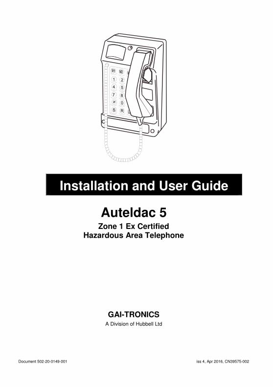
Document 502-20-0149-001 iss 4, Apr 2016, CN39575-002
Installation and User Guide
Auteldac 5 Zone 1 Ex Certified
Hazardous Area Telephone
GAI-TRONICS A Division of Hubbell Ltd

1 Auteldac 5
CONTENTS
1 SAFETY INFORMATION .............................................................. 2
2 PRODUCT DESCRIPTION ........................................................... 3
2.1 FEATURES ................................................................................... 4
3 INSTALLATION ............................................................................. 5
3.1 Dimensions .................................................................................... 5
3.2 Pre- installation .............................................................................. 5
3.3 Mounting Methods ......................................................................... 8
3.4 Connections and Cabling ............................................................ 10
3.5 Option Settings ............................................................................ 18
3.6 Reassembling the telephone enclosure ...................................... 20
4 OPERATION ............................................................................... 23
4.1 Keypad functions (18-button versions only) ................................ 24
4.2 Headset Operation ...................................................................... 25
5 MAINTENANCE .......................................................................... 26
5.1 Procedures .................................................................................. 26
5.2 Possible Operating Faults ........................................................... 26
5.3 Fault Finding & Field Repairs ...................................................... 27
6 TECHNICAL SPECIFICATIONS ................................................. 27
6.1 Hazardous Area Certification ...................................................... 27
6.2 Regulatory Compliance and Related Standards ......................... 29
6.3 Physical characteristics ............................................................... 31
6.4 Environmental specifications ....................................................... 31
6.5 Recycling information. ................................................................. 32
Auteldac 5 2
1 SAFETY INFORMATION
IMPORTANT:
ALL POSSIBLE MEASURES MUST BE TAKEN TO ENSURE WATER, FLUID OR DUST DOES NOT CONTAMINATE THE INTERNAL COMPONENTS OF THIS TELEPHONE WHILST UNPACKING, PREPARING OR INSTALLING IT, OR BY NEGLIGENCE.
FAILURE TO OBSERVE THIS PRECAUTION WILL INVALIDATE CERTIFICATION AND YOUR WARRANTY
Please read these instructions thoroughly before starting installation. These products must be installed by competent personnel familiar with the hazardous area regulations, as well as electrical and telephone installations.
The case must not be opened in the hazardous area unless all connections are isolated outside the hazardous area.
All glands and blanking plugs must be fitted with appropriate seals to maintain the required IP rating.
CAUTION: small metal objects may stick to the handset: please check before use
Some versions of this product are supplied with long handset or headset cables, which could present a trip hazard. Therefore care must be taken when using the handset/headset at extended distances, so that personnel or equipment in the vicinity are not impeded, trapped or entangled by the cord. Also, care must be taken to stow these long cord handset/headsets so they do not pose an entanglement or tripping hazard.
Noise level hazard. The telephone ringer can develop a sound level in excess of 90dBA @ 1 metre. Therefore, it is the installer’s responsibility to take the necessary measures to comply with any applicable regulations, for example the European directive 2003/10/EC on the minimum health and safety requirements regarding the exposure of workers to the risks arising from physical agents (noise).
3 Auteldac 5
2 PRODUCT DESCRIPTION
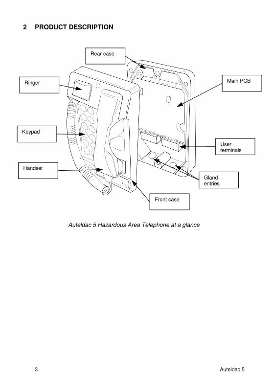
Auteldac 5 Hazardous Area Telephone at a glance
Rear case
Front case
Ringer
Handset
Keypad
Main PCB
User terminals
Gland entries
Auteldac 5 4
2.1 FEATURES
Auteldac 5 is an Ex certified telephone built to withstand arduous industrial atmospheres and environmental extremes. Features include:
• IEC Ex zone 1 certified for safe operation in hazardous areas
• Carbon loaded glass filled polyester body - rugged and corrosion free.
• Weather resistant up to IP66
• Rugged handset with curly cord or armoured stainless steel cord.
• Noise-cancelling handset option
• Magnetic hook-switch with no external moving parts
• Selectable Timer – can be set to go back on hook after 7 minutes
• Integral 90dBA ringer with volume adjustment.
• Selectable dial and recall modes
• Integral ring relay to activate external devices (see below)
• Integral hook relay to activate external devices (see below)
• Parallel telephone line connection terminal block
• One touch dial memories (18 button version only)
• Hearing aid compatible inductive coupling as standard
• Large, silicone rubber pushbuttons with alphanumeric keys
• Available in keypad (18 button) and no- keypad (hotline) versions
• Headset option available
5 Auteldac 5
3 INSTALLATION
Please read all these instructions thoroughly before starting installation.
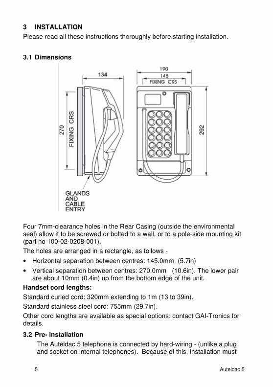
3.1 Dimensions
Four 7mm-clearance holes in the Rear Casing (outside the environmental seal) allow it to be screwed or bolted to a wall, or to a pole-side mounting kit (part no 100-02-0208-001).
The holes are arranged in a rectangle, as follows -
• Horizontal separation between centres: 145.0mm (5.7in)
• Vertical separation between centres: 270.0mm (10.6in). The lower pair are about 10mm (0.4in) up from the bottom edge of the unit.
Handset cord lengths:
Standard curled cord: 320mm extending to 1m (13 to 39in).
Standard stainless steel cord: 755mm (29.7in).
Other cord lengths are available as special options: contact GAI-Tronics for details.
3.2 Pre- installation
The Auteldac 5 telephone is connected by hard-wiring - (unlike a plug and socket on internal telephones). Because of this, installation must
Auteldac 5 6
be carried out by trained personnel. Contact GAI-Tronics if installation service is required.
The telephone is supplied suitable for vertical mounting only. Before installing the unit, please take note of the following:
• Glands. Glands are not supplied. All glands and cables must meet ‘Increased Safety’ (‘e’ type) requirements. Only ‘e’ type glands and suitable cables should be used and must be fitted correctly. For dust-certified variants, glands must meet IP66 minimum.
For gas only variants, glands must meet IP54 minimum.
The environmental rating of the telephone will not exceed that of the glands, i.e. in order to maintain an IP66 rating, IP66 glands must be used.
• Headset versions – Earth connection. If fitted with a headset socket, the unit must be connected to an equipotential bonding system for the whole area in which the intrinsically safe equipment is being used. See section 3.4.2 for details.
• Cable entries - Auteldac 5 has 2 M20 cable entry gland positions. Before installing, give consideration to the options available and review the alternative connection schemes in section 3.4.8 to ensure that the required connections can be made using the available glands.
If a high voltage is connected to the relay contacts (for example to activate a mains-powered beacon) then that cable must be segregated from all other cables and routed through its own gland.
Upon installation care should be taken to ensure that incoming cables are cleanly routed with a view to maintaining segregation between hazardous voltage cabling and the telephone's internal wiring (i.e. handset, hookswitch, ringer and headset if fitted).
ALL POSSIBLE MEASURES MUST BE TAKEN TO ENSURE WATER, FLUID OR DUST DOES NOT CONTAMINATE THE INTERNAL COMPONENTS OF THE TELEPHONE WHILST UNPACKING, PREPARING AND INSTALLING IT IN INCLEMENT WEATHER CONDITIONS OR BY NEGLIGENCE.
FAILURE TO TAKE THIS PRECAUTION WILL INVALIDATE YOUR WARRANTY AND CERTIFICATION
The telephone body must NOT be opened, nor glands removed or cables disconnected unless all supplies to the telephone, including telephone line cables, power cables and external devices have been isolated outside the hazardous area. Terminals for incoming cables are ‘e’ type and must be carefully connected so as to make an ‘e’ type termination.
7 Auteldac 5
The Code of Practice for ‘e’ type enclosures is specified in IEC60079-14. The installer and all service personnel should be familiar with the relevant sections of these documents.
If only one gland entry is used, the black Ex e sealing plug must be fitted to the unused entry.
1. Place the telephone on its base on a firm horizontal surface.
2. Using a 5mm Allen key, release the Front Casing from the Rear Casing. The screws are not captive in the Front Casing.
3. Noting their positions, disconnect the ribbon cable(s) and the ringer cable from the front section. See 3.6.
4. Take care when removing the Front Casing from the Rear Casing and storing the Front Casing not to damage the internal electronics, specifically the headset switch terminals or headset socket if fitted. To do so will violate the certification of the telephone product.
5. Check the condition of the sealing gasket (in the recess running round the edge of the front section), especially if the telephone has been previously used. If this seal shows any sign of damage or deterioration, it must be replaced prior to installing the telephone.
6. Remove the RED blanking plug from the cable entry hole leaving the Ex e certified (usually BLACK) blanking plug in situ.
NOTE: The Ex e plug must be used to seal the unused gland hole; failure to do so will invalidate the certification of the telephone product.
7. Select the appropriate size Ex gland for the cable used.
8. Take care when inserting the selected gland into the threaded cable entry hole. Follow the gland manufacturer’s instructions particularly with respect to sealing, installation and earthing.
9. After the glands have been fitted, select the required mounting method and follow the appropriate instructions below.
Auteldac 5 8
3.3 Mounting Methods
3.3.1 Wall Mounting
To ensure weatherproof integrity when wall mounted, external cables should enter the enclosure from the bottom via the two 20mm gland entries provided.
IMPORTANT WARNING:
DO NOT DRILL ANY EXTRA HOLES AS THIS WILL INVALIDATE
YOUR WARRANTY AND THE CERTIFICATION.
1. Remove rubber feet from the Rear Casing if fitted. Ensuring that the cable entries are at the bottom, offer the Rear Casing up to the vertical surface and mark through the fixing holes. Do not use the Rear Casing as a template to drill the holes. Work only from the marked positions.
2. Drill the holes in the vertical surface to suit the best method of fixing.
3. Ensure the Rear Casing is securely attached to the vertical surface using the four 7mm diameter screw holes provided. No sealing washers are necessary.
IMPORTANT: Do not use countersunk headed fixing screws. Only use round head, socket cap head or pan head screws. Take care not to over tighten the screws as doing so may damage the case and will invalidate your warranty and the certification.
4. Remove the terminal cover to allow access to the cable glands and terminals. Retain the cover to refit prior to putting the telephone into use.
5. Pass the cable through the gland and tighten, following the gland manufacturer’s instructions.
6. Continue the installation procedure with the connection of individual wires from the cable as described under sections 3.4 onwards.
9 Auteldac 5
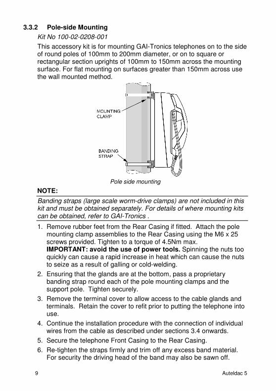
3.3.2 Pole-side Mounting
Kit No 100-02-0208-001
This accessory kit is for mounting GAI-Tronics telephones on to the side of round poles of 100mm to 200mm diameter, or on to square or rectangular section uprights of 100mm to 150mm across the mounting surface. For flat mounting on surfaces greater than 150mm across use the wall mounted method.
Pole side mounting
NOTE:
Banding straps (large scale worm-drive clamps) are not included in this kit and must be obtained separately. For details of where mounting kits can be obtained, refer to GAI-Tronics .
1. Remove rubber feet from the Rear Casing if fitted. Attach the pole mounting clamp assemblies to the Rear Casing using the M6 x 25 screws provided. Tighten to a torque of 4.5Nm max. IMPORTANT: avoid the use of power tools. Spinning the nuts too quickly can cause a rapid increase in heat which can cause the nuts to seize as a result of galling or cold-welding.
2. Ensuring that the glands are at the bottom, pass a proprietary banding strap round each of the pole mounting clamps and the support pole. Tighten securely.
3. Remove the terminal cover to allow access to the cable glands and terminals. Retain the cover to refit prior to putting the telephone into use.
4. Continue the installation procedure with the connection of individual wires from the cable as described under sections 3.4 onwards.
5. Secure the telephone Front Casing to the Rear Casing.
6. Re-tighten the straps firmly and trim off any excess band material. For security the driving head of the band may also be sawn off.

Auteldac 5 10
3.4 Connections and Cabling
IMPORTANT WARNING:-
ISOLATE MAINS AND TELEPHONE LINE OUTSIDE THE HAZARDOUS AREA BEFORE OPENING THE CASE.
ALL TERMINALS MUST BE CONNECTED IN ACCORDANCE WITH THIS INSTALLATION GUIDE. ANY DEVIATION FROM THIS MAY RESULT IN AN UNSAFE INSTALLATION AND VIOLATE THE CONDITIONS OF THE CERTIFICATION.
The connections to the Auteldac 5 are made via 2 terminal blocks below the main PCB. The cabling between the entry glands and the terminal blocks is covered by a terminal cover, secured by 2 screws as shown. Remove this cover to allow access to the terminals.
The terminal cover must be secured in place before re-assembling the telephone prior to use. The terminal cover provides the required isolation between the cabling in the rear section and the circuitry in the front section and is critical to the product's certification.
Terminal cover screws
Terminal blocks
Terminal cover
11 Auteldac 5
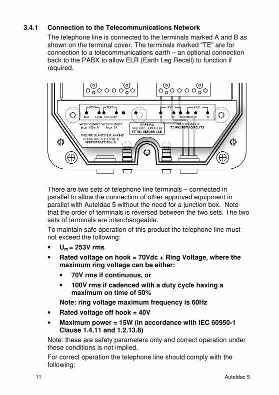
3.4.1 Connection to the Telecommunications Network
The telephone line is connected to the terminals marked A and B as shown on the terminal cover. The terminals marked “TE” are for connection to a telecommunications earth – an optional connection back to the PABX to allow ELR (Earth Leg Recall) to function if required.
There are two sets of telephone line terminals – connected in parallel to allow the connection of other approved equipment in parallel with Auteldac 5 without the need for a junction box. Note that the order of terminals is reversed between the two sets. The two sets of terminals are interchangeable.
To maintain safe operation of this product the telephone line must not exceed the following:
• Um = 253V rms
• Rated voltage on hook = 70Vdc + Ring Voltage, where the maximum ring voltage can be either:
• 70V rms if continuous, or
• 100V rms if cadenced with a duty cycle having a maximum on time of 50%
Note: ring voltage maximum frequency is 60Hz
• Rated voltage off hook = 40V
• Maximum power = 15W (in accordance with IEC 60950-1 Clause 1.4.11 and 1.2.13.8)
Note: these are safety parameters only and correct operation under these conditions is not implied.
For correct operation the telephone line should comply with the following:
Auteldac 5 12
• Ring Voltage: 30V to 100V rms, 20Hz to 50Hz
• Line voltage 20 to 70 Vdc
• Loop current ≥ 15mA
3.4.2 Earth Connection (Headset Version Only)
IMPORTANT: If fitted with a headset socket, Auteldac 5 must be connected to an equipotential bonding system for the whole area in which the intrinsically safe equipment is being used.
Versions with a headset socket are supplied with earth studs and link wires, and must be connected to earth as shown.
This earth connection is a condition of the certificate for headset versions.
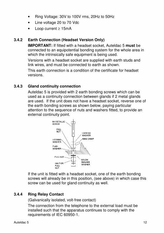
3.4.3 Gland continuity connection
Auteldac 5 is provided with 2 earth bonding screws which can be used as a continuity connection between glands if 2 metal glands are used. If the unit does not have a headset socket, reverse one of the earth bonding screws as shown below, paying particular attention to the sequence of nuts and washers fitted, to provide an external continuity point.
If the unit is fitted with a headset socket, one of the earth bonding screws will already be in this position, (see above) in which case this screw can be used for gland continuity as well.
3.4.4 Ring Relay Contact
(Galvanically isolated, volt-free contact)
The connection from the telephone to the external load must be installed such that the apparatus continues to comply with the requirements of IEC 60950-1.
13 Auteldac 5
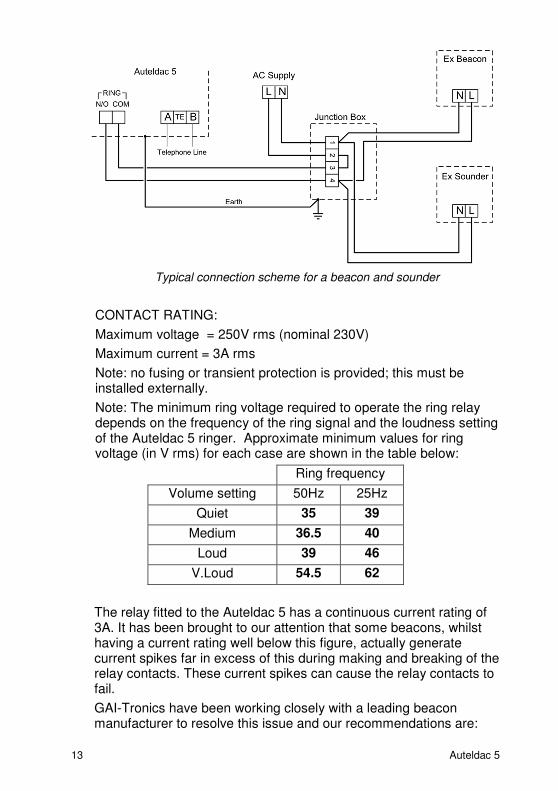
Typical connection scheme for a beacon and sounder
CONTACT RATING:
Maximum voltage = 250V rms (nominal 230V)
Maximum current = 3A rms
Note: no fusing or transient protection is provided; this must be installed externally.
Note: The minimum ring voltage required to operate the ring relay depends on the frequency of the ring signal and the loudness setting of the Auteldac 5 ringer. Approximate minimum values for ring voltage (in V rms) for each case are shown in the table below:
Ring frequency
Volume setting 50Hz 25Hz
Quiet 35 39
Medium 36.5 40
Loud 39 46
V.Loud 54.5 62
The relay fitted to the Auteldac 5 has a continuous current rating of 3A. It has been brought to our attention that some beacons, whilst having a current rating well below this figure, actually generate current spikes far in excess of this during making and breaking of the relay contacts. These current spikes can cause the relay contacts to fail.
GAI-Tronics have been working closely with a leading beacon manufacturer to resolve this issue and our recommendations are:
Auteldac 5 14
• Restrict the use of beacons to non AC variants only or those with a maximum flash intensity of 5 joules.
• Where beacons with greater than 5 joule flash intensity are required, the beacons should be purchased directly from GAI-Tronics, who will ensure compatibility with the Auteldac 5 and that certification parameters are not compromised.
3.4.5 Hook Switch State Indicator Contact
(Optically isolated, volt-free contact)
The connection from the telephone to the hook switch state indicator must be installed such that the apparatus continues to comply with the requirements of IEC 60950-1 Maximum voltage = 250Vrms
Maximum current = 150mA rms
Note: no fusing or transient protection is provided; this must be installed externally.
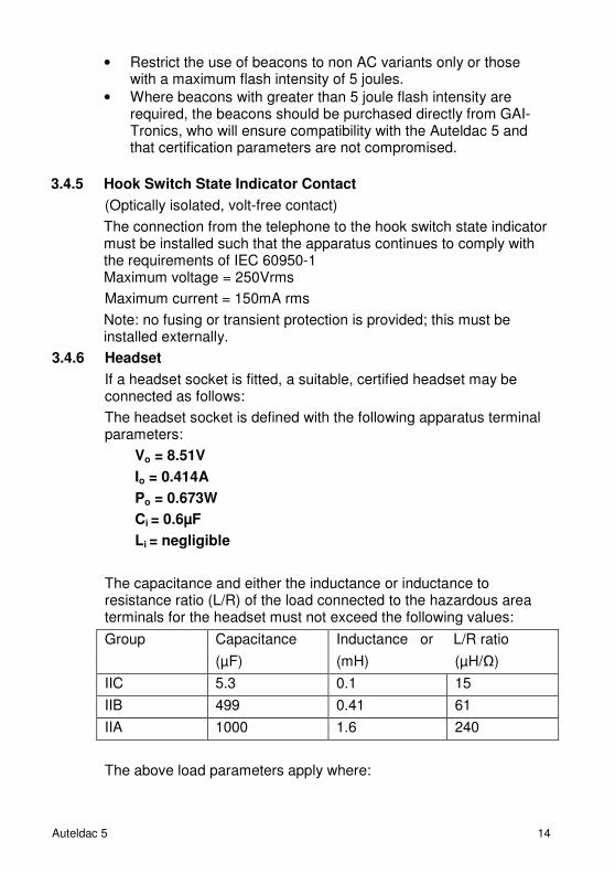
3.4.6 Headset
If a headset socket is fitted, a suitable, certified headset may be connected as follows:
The headset socket is defined with the following apparatus terminal parameters:
Vo = 8.51V
Io = 0.414A
Po = 0.673W
Ci = 0.6µF
Li = negligible
The capacitance and either the inductance or inductance to resistance ratio (L/R) of the load connected to the hazardous area terminals for the headset must not exceed the following values:
Group Capacitance Inductance or L/R ratio
(µF) (mH) (µH/Ω)
IIC 5.3 0.1 15
IIB 499 0.41 61
IIA 1000 1.6 240
The above load parameters apply where:
15 Auteldac 5
1. The external circuit contains no combined lumped inductance Li and capacitance Ci greater than 1% of the above values, or
2. The inductance and capacitance are distributed as in a cable, or
3. The external circuit contains either only lumped inductance or lumped capacitance in combination with a cable
In all other situations e.g. the external circuit contains combined lumped inductance and lumped capacitance, up to 50% of each of the L and C values is allowed.
The headset must be used in accordance with the manufacturer’s instructions and certification (supplied with headset).
3.4.7 Optional Headset Extension lead
A separate headset extension lead is available as an optional extra, allowing the operator to extend the headset cord by up to a further 4 metres. Note: Refer to section 1 for hazard warnings regarding long corded headsets & handsets.
3.4.8 Alternative cabling schemes
Depending on the options used, different cabling permutations are possible; some examples are shown below.
Upon installation care should be taken to ensure that incoming cables are cleanly routed with a view to maintaining segregation from the telephone's internal wiring (i.e. handset, hookswitch, ringer and headset if fitted). Segregation must also be maintained between telephone line and cables to the contacts.
For clarity, the illustrations below are shown with the terminal cover removed.
The terminal cover must be secured in place before re-assembling the telephone prior to use. The terminal cover provides the required isolation between the cabling in the rear section and the circuitry in the front section and is critical to the product's certification.
Auteldac 5 16
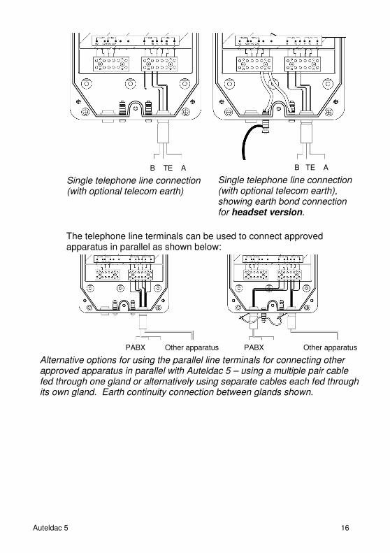
The telephone line terminals can be used to connect approved apparatus in parallel as shown below:
B TE A
Single telephone line connection (with optional telecom earth)
B TE A
Single telephone line connection (with optional telecom earth), showing earth bond connection for headset version.
PABX Other apparatus PABX Other apparatus
Alternative options for using the parallel line terminals for connecting other approved apparatus in parallel with Auteldac 5 – using a multiple pair cable fed through one gland or alternatively using separate cables each fed through its own gland. Earth continuity connection between glands shown.
17 Auteldac 5
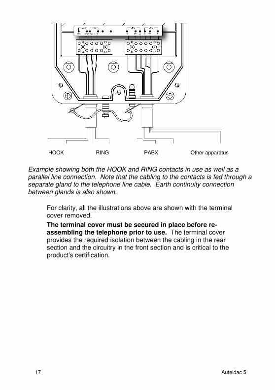
For clarity, all the illustrations above are shown with the terminal cover removed.
The terminal cover must be secured in place before re-assembling the telephone prior to use. The terminal cover provides the required isolation between the cabling in the rear section and the circuitry in the front section and is critical to the product's certification.
HOOK RING PABX Other apparatus
Example showing both the HOOK and RING contacts in use as well as a parallel line connection. Note that the cabling to the contacts is fed through a separate gland to the telephone line cable. Earth continuity connection between glands is also shown.
Auteldac 5 18
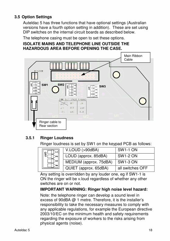
3.5 Option Settings
Auteldac 5 has three functions that have optional settings (Australian versions have a fourth option setting in addition). These are set using DIP switches on the internal circuit boards as described below.
The telephone casing must be open to set these options.
ISOLATE MAINS AND TELEPHONE LINE OUTSIDE THE HAZARDOUS AREA BEFORE OPENING THE CASE.
3.5.1 Ringer Loudness
Ringer loudness is set by SW1 on the keypad PCB as follows:
V.LOUD (>90dBA) SW1-1 ON
LOUD (approx. 85dBA) SW1-2 ON
MEDIUM (approx. 75dBA) SW1-3 ON
QUIET (approx. 65dBA) all switches OFF
Any setting is overridden by any louder one, eg if SW1-1 is ON the ringer will be v.loud regardless of whether any other switches are on or not.
IMPORTANT WARNING: Ringer high noise level hazard:
Note: the telephone ringer can develop a sound level in excess of 90dBA @ 1 metre. Therefore, it is the installer’s responsibility to take the necessary measures to comply with any applicable regulations, for example the European directive 2003/10/EC on the minimum health and safety requirements regarding the exposure of workers to the risks arising from physical agents (noise).
Main Ribbon Cable
Ringer cable to Rear section
19 Auteldac 5
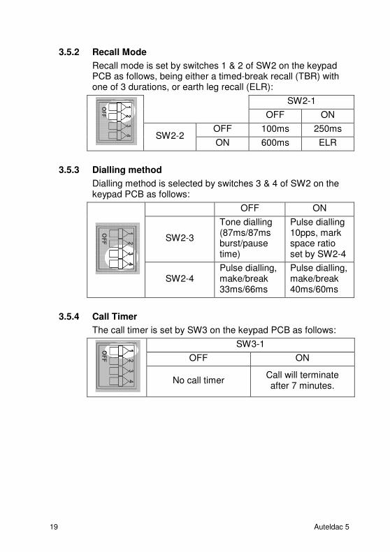
3.5.2 Recall Mode
Recall mode is set by switches 1 & 2 of SW2 on the keypad PCB as follows, being either a timed-break recall (TBR) with one of 3 durations, or earth leg recall (ELR):
SW2-1
OFF ON
SW2-2 OFF 100ms 250ms
ON 600ms ELR
3.5.3 Dialling method
Dialling method is selected by switches 3 & 4 of SW2 on the keypad PCB as follows:
OFF ON
SW2-3
Tone dialling (87ms/87ms burst/pause time)
Pulse dialling 10pps, mark space ratio set by SW2-4
SW2-4 Pulse dialling, make/break 33ms/66ms
Pulse dialling, make/break 40ms/60ms
3.5.4 Call Timer
The call timer is set by SW3 on the keypad PCB as follows:
SW3-1
OFF ON
No call timer Call will terminate after 7 minutes.
Auteldac 5 20
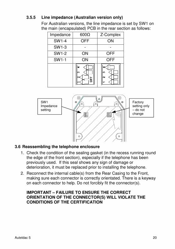
3.5.5 Line impedance (Australian version only)
For Australian versions, the line impedance is set by SW1 on the main (encapsulated) PCB in the rear section as follows:
Impedance 600Ω Z-Complex
SW1-4 OFF ON
SW1-3 - -
SW1-2 ON OFF
SW1-1 ON OFF
3.6 Reassembling the telephone enclosure
1. Check the condition of the sealing gasket (in the recess running round the edge of the front section), especially if the telephone has been previously used. If this seal shows any sign of damage or deterioration, it must be replaced prior to installing the telephone.
2. Reconnect the internal cable(s) from the Rear Casing to the Front, making sure each connector is correctly orientated. There is a keyway on each connector to help. Do not forcibly fit the connector(s). IMPORTANT – FAILURE TO ENSURE THE CORRECT ORIENTATION OF THE CONNECTOR(S) WILL VIOLATE THE CONDITIONS OF THE CERTIFICATION
Factory setting only – do not change
SW1 Impedance setting
21 Auteldac 5
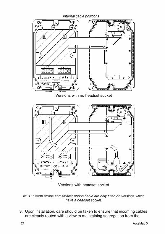
Internal cable positions
Versions with no headset socket
Versions with headset socket
NOTE: earth straps and smaller ribbon cable are only fitted on versions which have a headset socket.
3. Upon installation, care should be taken to ensure that incoming cables are cleanly routed with a view to maintaining segregation from the
Auteldac 5 22
telephone's internal wiring (i.e. handset, hookswitch, ringer and headset switch / socket if fitted).
4. Ensure that the terminal cover is fitted. The terminal cover provides the required isolation between the cabling in the rear section and the circuitry in the front section and is critical to the product's certification.
5. Offer the Front Casing to the Rear Casing, with the internal cables arranged as shown above; ensure that the cable(s) will not be trapped when the Front Casing is tightened down. Take care that the large ribbon cable can lay flat and that the insulation can not become damaged. IMPORTANT - DAMAGED INSULATION WILL VIOLATE THE CONDITIONS OF THE CERTIFICATION.
6. Tighten the three screws firmly to secure the front case to the rear.
7. Auteldac 5 is now ready for use.
23 Auteldac 5
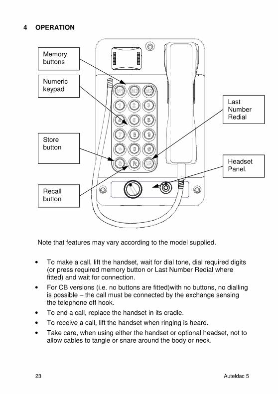
4 OPERATION
Note that features may vary according to the model supplied.
• To make a call, lift the handset, wait for dial tone, dial required digits (or press required memory button or Last Number Redial where fitted) and wait for connection.
• For CB versions (i.e. no buttons are fitted)with no buttons, no dialling is possible – the call must be connected by the exchange sensing the telephone off hook.
• To end a call, replace the handset in its cradle.
• To receive a call, lift the handset when ringing is heard.
• Take care, when using either the handset or optional headset, not to allow cables to tangle or snare around the body or neck.
Memory buttons
Numeric keypad
Store button
Recall button
Headset Panel.
Last Number Redial
Auteldac 5 24
4.1 Keypad functions (18-button versions only)
Last Number Redial
Press LR to redial the last dialled number.
Recall Function
Press R to send a “recall” signal to the exchange. The type of recall can be selected (see section 3.5.2).
Programming
The three memory buttons, M1, M2 and M3 may each be programmed with up to 17 digits for one touch memory dialling.
The telephone needs to be connected to a telephone line (ie powered) to program it, and the case does not need to be opened, so it can be programmed in the hazardous area.
To program a number:
• Lift the handset
• Press S
• Enter the required digits
• Press S again
• Press the required memory button, M1, M2 or M3
• Replace the handset

25 Auteldac 5
4.2 Headset Operation
(refer to section 1 for hazard warning)
The Auteldac 5 can be supplied fitted with a headset panel, permitting hands-free operation using a suitable, certified headset.
To use:
1. Insert headset plug into marked connector, observing keyway.
2. To make or answer a call, turn the switch to the ‘I’ position.
3. To terminate the call, turn the switch to the ‘0’ position.
To remove the headset, pull the body of the connector to release the latching mechanism. Do not attempt to disconnect the headset by pulling the cable as damage may result. A dust cover is provided. Ensure that the dust cover is fitted to protect the socket when not in use.
NOTE: If the handset is lifted during a call using the headset, the handset microphone will be muted. The handset can be used normally if a call is not in progress via the headset.
The headset must be used in accordance with the manufacturer’s instructions and certification (supplied with headset).
Auteldac 5 26
The headset interface of the Auteldac 5 has been certified as intrinsically safe. Therefore, it is permissible to connect and disconnect the headset in a hazardous area.
5 MAINTENANCE
The Auteldac 5 is based on highly reliable integrated circuits.
Under normal operation, the telephone is maintenance free.
5.1 Procedures
A programme of regular external visual inspection and cleaning is recommended, with particular attention being paid to -
On all models:
• Overall cleanliness of the telephone:
Wipe clean as necessary with a cloth dampened with clear water.
If heavily soiled, a little dishwashing liquid may be used in addition.
NOTE: high pressure hoses should not be used for cleaning.
• Security of the installation on wall, pole or post.
• Security and integrity of cable entries.
• Security of the three body screws.
• Cleanliness, integrity and condition of the handset:
Wipe clean as necessary with a cloth dampened with clear water, and disinfect the handset.
Note that the handset has an anti-static coating – take care not to damage this by excessive rubbing or the use of chemicals or solvents (e.g. petroleum spirit). Do not allow liquid to penetrate the earpiece or mouthpiece.
• Security and condition of the handset cable.
On headset models, refer to headset manufacturer’s manual for cleaning, hygiene and maintenance of headset.
5.2 Possible Operating Faults
The following operating and installation conditions could give rise to faults. During installation, or in the event of a fault, please ensure that the following do not occur:
• Water ingress
• Incorrect positioning of internal cables (Section 3.6)
• Damage to any internal components
• Overstressing of screws
• Insecure fixing
27 Auteldac 5
• Incorrect installation of glands (Section 3.2)
• Incorrect wiring or cable connections (Section 3.4)
• Improper reassembly following connection
• Additional holes drilled in casing
5.3 Fault Finding & Field Repairs
The Auteldac 5 contains no user serviceable parts and in the event of damage or failure must be replaced with a tested telephone of the correct type.
Refer to section 5.2 for a list of possible fault conditions.
6 TECHNICAL SPECIFICATIONS
6.1 Hazardous Area Certification
It is the responsibility of the installer or user to determine whether or not Auteldac 5 is suitable for use in a given location or particular circumstances.
6.1.1 Dust Certification
Certain models (only those fitted with curly cord handsets and with no headset connector) are certified for use in the presence of combustible dust. These models have a YELLOW certification label, whereas gas-only models have a BLUE certification label. Certification details are listed below.
6.1.2 IEC Ex Certification
Certificate number: IECEx BAS 14.0165
Certification details:
Gas certified variants (BLUE certification label):
Ex e ib mb IIC T4 Gb (-20°C ≤ Ta ≤ +60°C)
Ex e ib mb IIC T5 Gb (-20°C ≤ Ta ≤ +50°C) Gas & Dust certified variants (YELLOW certification label):
Ex e ib mb IIC T4 Gb (-20°C ≤ Ta ≤ +60°C)
Ex e ib mb IIC T5 Gb (-20°C ≤ Ta ≤ +50°C)
Auteldac 5 28
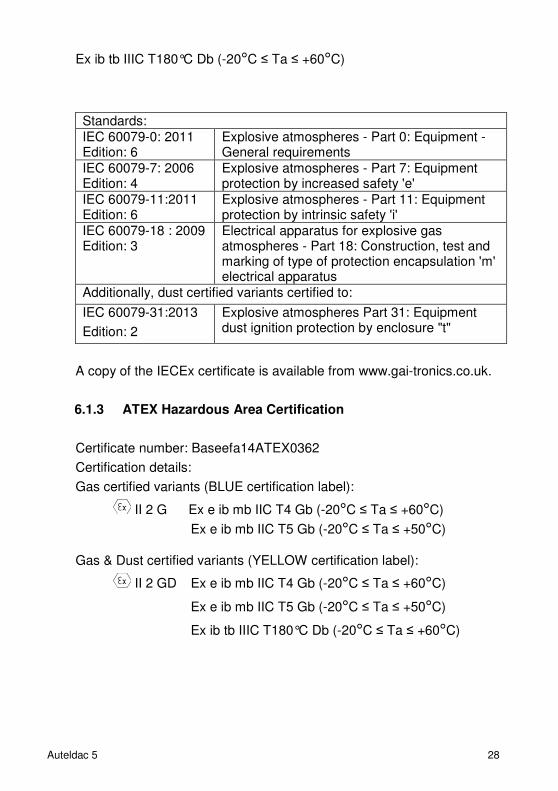
Ex ib tb IIIC T180°C Db (-20°C ≤ Ta ≤ +60°C)
A copy of the IECEx certificate is available from www.gai-tronics.co.uk.
6.1.3 ATEX Hazardous Area Certification
Certificate number: Baseefa14ATEX0362
Certification details:
Gas certified variants (BLUE certification label):
II 2 G Ex e ib mb IIC T4 Gb (-20°C ≤ Ta ≤ +60°C)
Ex e ib mb IIC T5 Gb (-20°C ≤ Ta ≤ +50°C)
Gas & Dust certified variants (YELLOW certification label):
II 2 GD Ex e ib mb IIC T4 Gb (-20°C ≤ Ta ≤ +60°C)
Ex e ib mb IIC T5 Gb (-20°C ≤ Ta ≤ +50°C)
Ex ib tb IIIC T180°C Db (-20°C ≤ Ta ≤ +60°C)
Standards:
IEC 60079-0: 2011 Edition: 6
Explosive atmospheres - Part 0: Equipment - General requirements
IEC 60079-7: 2006 Edition: 4
Explosive atmospheres - Part 7: Equipment protection by increased safety 'e'
IEC 60079-11:2011 Edition: 6
Explosive atmospheres - Part 11: Equipment protection by intrinsic safety 'i'
IEC 60079-18 : 2009 Edition: 3
Electrical apparatus for explosive gas atmospheres - Part 18: Construction, test and marking of type of protection encapsulation 'm' electrical apparatus
Additionally, dust certified variants certified to:
IEC 60079-31:2013
Edition: 2
Explosive atmospheres Part 31: Equipment dust ignition protection by enclosure "t"
29 Auteldac 5
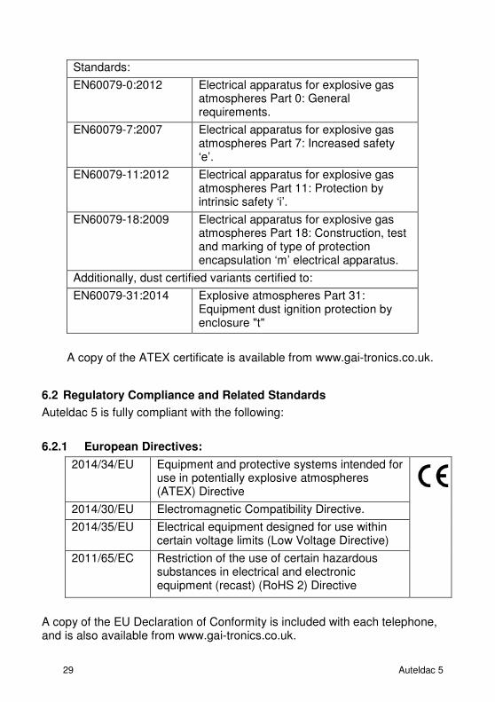
A copy of the ATEX certificate is available from www.gai-tronics.co.uk.
6.2 Regulatory Compliance and Related Standards
Auteldac 5 is fully compliant with the following:
6.2.1 European Directives:
2014/34/EU Equipment and protective systems intended for use in potentially explosive atmospheres (ATEX) Directive
2014/30/EU Electromagnetic Compatibility Directive.
2014/35/EU Electrical equipment designed for use within certain voltage limits (Low Voltage Directive)
2011/65/EC Restriction of the use of certain hazardous substances in electrical and electronic equipment (recast) (RoHS 2) Directive
A copy of the EU Declaration of Conformity is included with each telephone, and is also available from www.gai-tronics.co.uk.
Standards:
EN60079-0:2012 Electrical apparatus for explosive gas atmospheres Part 0: General requirements.
EN60079-7:2007 Electrical apparatus for explosive gas atmospheres Part 7: Increased safety ‘e’.
EN60079-11:2012 Electrical apparatus for explosive gas atmospheres Part 11: Protection by intrinsic safety ‘i’.
EN60079-18:2009 Electrical apparatus for explosive gas atmospheres Part 18: Construction, test and marking of type of protection encapsulation ‘m’ electrical apparatus.
Additionally, dust certified variants certified to:
EN60079-31:2014 Explosive atmospheres Part 31: Equipment dust ignition protection by enclosure "t"
Auteldac 5 30
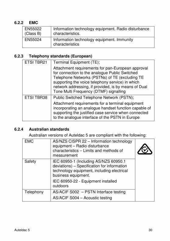
6.2.2 EMC
EN55022 (Class B)
Information technology equipment. Radio disturbance characteristics.
EN55024 Information technology equipment. Immunity characteristics
6.2.3 Telephony standards (European)
ETSI TBR21 Terminal Equipment (TE);
Attachment requirements for pan-European approval for connection to the analogue Public Switched Telephone Networks (PSTNs) of TE (excluding TE supporting the voice telephony service) in which network addressing, if provided, is by means of Dual Tone Multi Frequency (DTMF) signalling
ETSI TBR38 Public Switched Telephone Network (PSTN);
Attachment requirements for a terminal equipment incorporating an analogue handset function capable of supporting the justified case service when connected to the analogue interface of the PSTN in Europe
6.2.4 Australian standards
Australian versions of Auteldac 5 are compliant with the following:
EMC AS/NZS CISPR 22 – Information technology equipment – Radio disturbance characteristics – Limits and methods of measurement
Safety IEC 60950-1 (Including AS/NZS 60950.1 deviations) – Specification for information technology equipment, including electrical business equipment.
IEC 60950-22 - Equipment installed outdoors
Telephony AS/ACIF S002 – PSTN Interface testing
AS/ACIF S004 – Acoustic testing
31 Auteldac 5
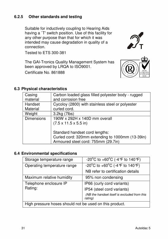
6.2.5 Other standards and testing
Suitable for inductively coupling to Hearing Aids having a `T' switch position. Use of this facility for any other purpose than that for which it was intended may cause degradation in quality of a connection.
Tested to ETS 300-381
The GAI-Tronics Quality Management System has been approved by LRQA to ISO9001.
Certificate No. 861888
6.3 Physical characteristics
Casing material
Carbon loaded glass filled polyester body - rugged and corrosion free
Handset Material
Cycoloy (2800) with stainless steel or polyester curled cord.
Weight 3.2kg (7lbs)
Dimensions 190W x 292H x 140D mm overall (7.5 x 11.5 x 5.5 in) Standard handset cord lengths: Curled cord: 320mm extending to 1000mm (13-39in) Armoured steel cord: 755mm (29.7in)
6.4 Environmental specifications
Storage temperature range -20oC to +60
oC (-4°F to 140°F)
Operating temperature range -20oC to +60
oC (-4°F to 140°F)
NB refer to certification details
Maximum relative humidity 95% non condensing
Telephone enclosure IP Rating:
IP66 (curly cord variants)
IP54 (steel cord variants)
(NB the handset itself is excluded from this rating)
High pressure hoses should not be used on this product.
Auteldac 5 32
6.5 Recycling information.
The symbol shown here and on the product means that the product is classed as Electrical or Electronic Equipment and should not be disposed with other household or commercial waste at the end of its working life.
The Waste of Electrical and Electronic Equipment (WEEE) Directive has been put in place to recycle products using best available recovery and recycling techniques to minimise the impact on the environment, treat any hazardous substances and avoid the increasing landfill.
Business users should contact their suppliers and check the terms and conditions of the purchase contract and ensure that this product is not mixed with other commercial waste for disposal.

33 Auteldac 5

Auteldac 5 34
35 Auteldac 5
GAI-TRONICS A division of Hubbell Ltd.
Brunel Drive
Stretton Park
Burton upon Trent
Staffordshire
DE13 0BZ
www.gai-tronics.co.uk
Tel: +44 (0)1283 500 500
Fax: +44 (0)1283 500 400
If you have any difficulties, please call.
The policy of GAI-Tronics is one of continuous improvement, therefore the Company reserves the right to change
specifications without notice.
The contents of this publication are confidential, are the property of GAI-Tronics, and may not be reproduced, wholly or in part, without their written permission.
E&OE.