Embed Size (px)
Citation preview
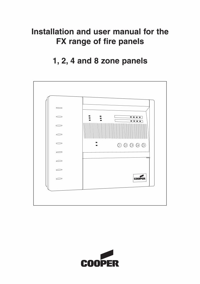
Installation and user manual for theFX range of fire panels
1, 2, 4 and 8 zone panels
Contents
2
Panel installation 3
Panel connections 3
Wiring connection drawings 4
Panel facilities 6
Installation check 8
Commissioning
User information
Maintenance
Tables
Sounder and Visual Indication 9
Technical Specification 9
General Wiring
3
InstallationPlease read the following instructions before installing and wiringthe fire alarm panel.
This range of panels are EN54 parts 2 and 4 certified and havebeen designed to comply with BS5839 part 1:2002 installations.The panels have two optional features:-FIRE ALARM DEVICES: (EN54 part 2 clause 7.8)TEST CONDITION: (EN54 part 2 clause 10.0)
In common with all electrical equipment the panel should beinstalled in a clean, dry, well ventilated area, not in direct sun lightand avoiding cold areas where possible. Note, temperatures inexcess of 40°C will affect the panel operation. The panel shouldbe located away from any potential hazard, in a position where itis readily accessible to authorised staff and the fire services.Ideally on the perimeter of a building near a permanent entrance.
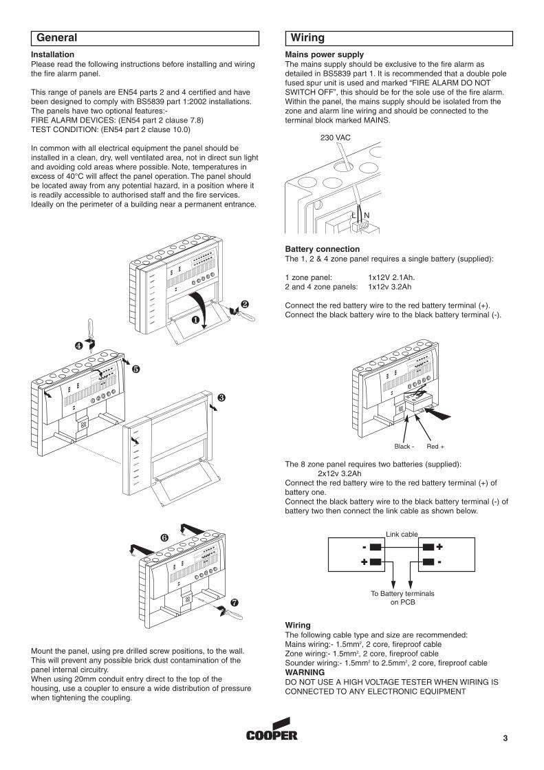
Mains power supplyThe mains supply should be exclusive to the fire alarm asdetailed in BS5839 part 1. It is recommended that a double polefused spur unit is used and marked “FIRE ALARM DO NOTSWITCH OFF”, this should be for the sole use of the fire alarm.Within the panel, the mains supply should be isolated from thezone and alarm line wiring and should be connected to theterminal block marked MAINS.
Battery connectionThe 1, 2 & 4 zone panel requires a single battery (supplied):
1 zone panel: 1x12V 2.1Ah.2 and 4 zone panels: 1x12v 3.2Ah
Connect the red battery wire to the red battery terminal (+).Connect the black battery wire to the black battery terminal (-).
The 8 zone panel requires two batteries (supplied):2x12v 3.2Ah
Connect the red battery wire to the red battery terminal (+) ofbattery one.Connect the black battery wire to the black battery terminal (-) ofbattery two then connect the link cable as shown below.
Mount the panel, using pre drilled screw positions, to the wall.This will prevent any possible brick dust contamination of thepanel internal circuitry.When using 20mm conduit entry direct to the top of thehousing, use a coupler to ensure a wide distribution of pressurewhen tightening the coupling.
WiringThe following cable type and size are recommended:Mains wiring:- 1.5mm2, 2 core, fireproof cableZone wiring:- 1.5mm2, 2 core, fireproof cableSounder wiring:- 1.5mm2 to 2.5mm2, 2 core, fireproof cableWARNINGDO NOT USE A HIGH VOLTAGE TESTER WHEN WIRING ISCONNECTED TO ANY ELECTRONIC EQUIPMENT
�
�
�
�
�
�
�
230 VAC
L
Black - Red +
N
Wiring connection drawings
4
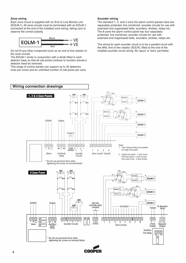
Zone wiringEach zone circuit is supplied with an End of Line Monitor unit(EOLM-1). All zone circuits must be terminated with an EOLM-1,connected at the end of the installed zone wiring, taking care toobserve the correct polarity.
Do not fit any other component such as an end of line resistor tothe zone circuits.The EOLM-1 works in conjunction with a diode fitted in eachdetector base so that all call points continue to function should adetector head be removed.This range of control panels can support up to 32 detectors(max per zone) and an unlimited number of call points per zone.
Sounder wiringThe standard 1, 2, and 4 zone fire alarm control panels have twoseparately protected, line monitored, sounder circuits for use withpolarised and suppressed bells, sounders, strobes, relays etc.The 8 zone fire alarm control panel has four separatelyprotected, line monitored, sounder circuits for use withpolarised and suppressed bells, sounders, strobes, relays etc.
The wiring for each sounder circuit is to be a parallel circuit withthe 6K8, end of line resistor (EOLR), fitted at the end of theinstalled sounder circuit wiring. No ‘spurs’ or ‘tee’s’ permitted.
+_
5
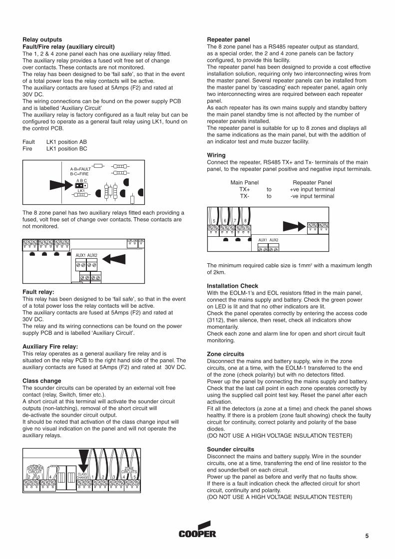
Relay outputsFault/Fire relay (auxiliary circuit)The 1, 2 & 4 zone panel each has one auxiliary relay fitted.The auxiliary relay provides a fused volt free set of changeover contacts. These contacts are not monitored.The relay has been designed to be ‘fail safe’, so that in the eventof a total power loss the relay contacts will be active.The auxiliary contacts are fused at 5Amps (F2) and rated at30V DC.The wiring connections can be found on the power supply PCBand is labelled ‘Auxiliary Circuit’The auxiliary relay is factory configured as a fault relay but can beconfigured to operate as a general fault relay using LK1, found onthe control PCB.
Fault LK1 position ABFire LK1 position BC
Repeater panel The 8 zone panel has a RS485 repeater output as standard,as a special order, the 2 and 4 zone panels can be factoryconfigured, to provide this facility.The repeater panel has been designed to provide a cost effectiveinstallation solution, requiring only two interconnecting wires fromthe master panel. Several repeater panels can be installed fromthe master panel by ‘cascading’ each repeater panel, again onlytwo interconnecting wires are required between each repeaterpanel.As each repeater has its own mains supply and standby batterythe main panel standby time is not affected by the number ofrepeater panels installed.The repeater panel is suitable for up to 8 zones and displays allthe same indications as the main panel, but with the addition ofan indicator test and mute buzzer facility.
WiringConnect the repeater, RS485 TX+ and Tx- terminals of the mainpanel, to the repeater panel positive and negative input terminals.
Main Panel Repeater PanelTX+ to +ve input terminalTX- to -ve input terminal
The minimum required cable size is 1mm2 with a maximum lengthof 2km.
Installation CheckWith the EOLM-1’s and EOL resistors fitted in the main panel,connect the mains supply and battery. Check the green poweron LED is lit and that no other indicators are lit.Check the panel operates correctly by entering the access code(3112), then silence, then reset, check all indicators showmomentarily.Check each zone and alarm line for open and short circuit faultmonitoring.
Zone circuitsDisconnect the mains and battery supply, wire in the zonecircuits, one at a time, with the EOLM-1 transferred to the endof the zone (check polarity) but with no detectors fitted.Power up the panel by connecting the mains supply and battery.Check that the last call point in each zone operates correctly byusing the supplied call point test key. Reset the panel after eachactivation.Fit all the detectors (a zone at a time) and check the panel showshealthy. If there is a problem (zone fault showing) check the faultycircuit for continuity, correct polarity and polarity of the basediodes.(DO NOT USE A HIGH VOLTAGE INSULATION TESTER)
Sounder circuitsDisconnect the mains and battery supply. Wire in the soundercircuits, one at a time, transferring the end of line resistor to theend sounder/bell on each circuit.Power up the panel as before and verify that no faults show.If there is a fault indication check the affected circuit for shortcircuit, continuity and polarity.(DO NOT USE A HIGH VOLTAGE INSULATION TESTER)
The 8 zone panel has two auxiliary relays fitted each providing afused, volt free set of change over contacts. These contacts arenot monitored.
Fault relay:This relay has been designed to be ‘fail safe’, so that in the eventof a total power loss the relay contacts will be active.The auxiliary contacts are fused at 5Amps (F2) and rated at30V DC.The relay and its wiring connections can be found on the powersupply PCB and is labelled ‘Auxiliary Circuit’.
Auxiliary Fire relay:This relay operates as a general auxiliary fire relay and issituated on the relay PCB to the right hand side of the panel. Theauxiliary contacts are fused at 5Amps (F2) and rated at 30V DC.
Class changeThe sounder circuits can be operated by an external volt freecontact (relay, Switch, timer etc.).A short circuit at this terminal will activate the sounder circuitoutputs (non-latching), removal of the short circuit willde-activate the sounder circuit output.It should be noted that activation of the class change input willgive no visual indication on the panel and will not operate theauxiliary relays.
Commissioning the system
User information
6
Assuming that the installation instructions and installation checkshave been carried out successfully the fire alarm system is readyfor commissioning.Each detector and call point should be tested in turn to ensurethat it operates, indicates the correct zone fire LED and operatesthe alarm output correctly, ensuring all sounders/bells operate.
Walk test facilityA walk test function has been included in this range of panels toenable one person (electrical contractor or installer) to test thefire detection system without an assistant. This function is for thesole use of the electrical contractor or installer and not for normaloperational use.
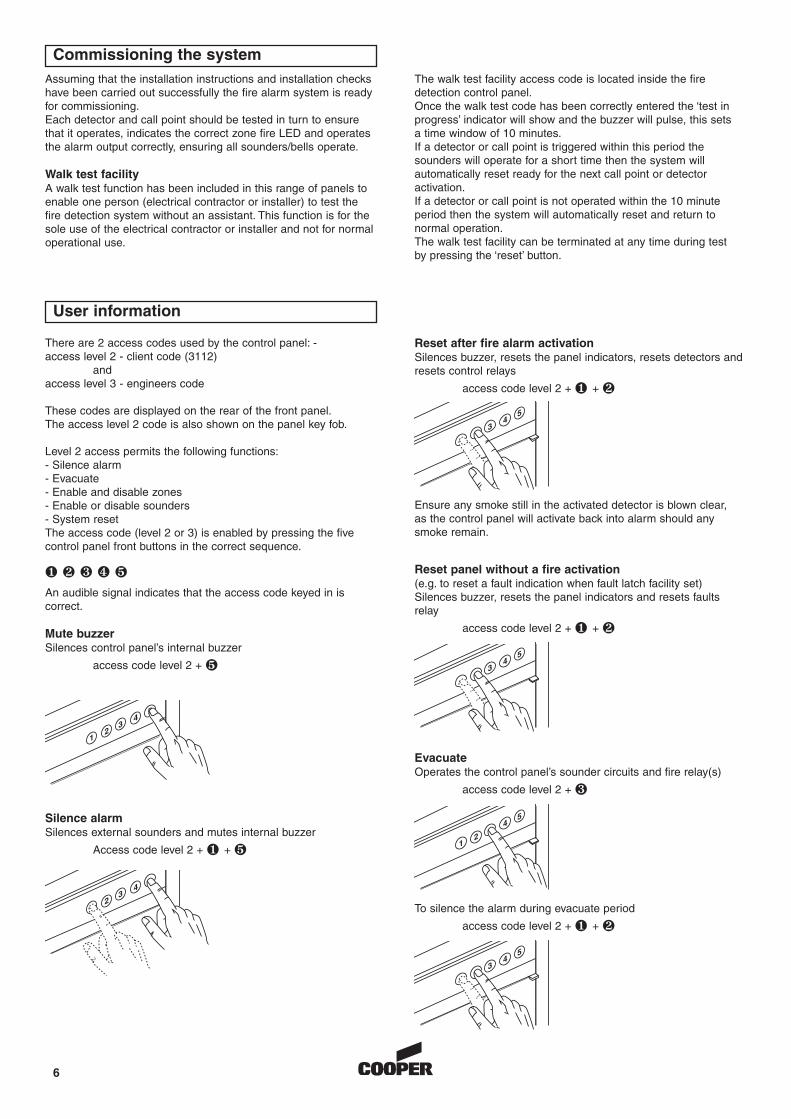
Silence alarmSilences external sounders and mutes internal buzzer
Access code level 2 + � + �
EvacuateOperates the control panel’s sounder circuits and fire relay(s)
access code level 2 + �
Reset after fire alarm activationSilences buzzer, resets the panel indicators, resets detectors andresets control relays
access code level 2 + � + �
Ensure any smoke still in the activated detector is blown clear,as the control panel will activate back into alarm should anysmoke remain.
Reset panel without a fire activation(e.g. to reset a fault indication when fault latch facility set)Silences buzzer, resets the panel indicators and resets faultsrelay
access code level 2 + � + �
There are 2 access codes used by the control panel: -access level 2 - client code (3112)
and access level 3 - engineers code
These codes are displayed on the rear of the front panel.The access level 2 code is also shown on the panel key fob.
Level 2 access permits the following functions:- Silence alarm- Evacuate- Enable and disable zones- Enable or disable sounders- System resetThe access code (level 2 or 3) is enabled by pressing the fivecontrol panel front buttons in the correct sequence.
� � � � �
An audible signal indicates that the access code keyed in iscorrect.
Mute buzzerSilences control panel’s internal buzzer
access code level 2 + �
The walk test facility access code is located inside the firedetection control panel.Once the walk test code has been correctly entered the ‘test inprogress’ indicator will show and the buzzer will pulse, this setsa time window of 10 minutes.If a detector or call point is triggered within this period thesounders will operate for a short time then the system willautomatically reset ready for the next call point or detectoractivation.If a detector or call point is not operated within the 10 minuteperiod then the system will automatically reset and return tonormal operation.The walk test facility can be terminated at any time during testby pressing the ‘reset’ button.
12
34
5
23
4
12
45
To silence the alarm during evacuate period
access code level 2 + � + �
34
5
34
5
34
5
7
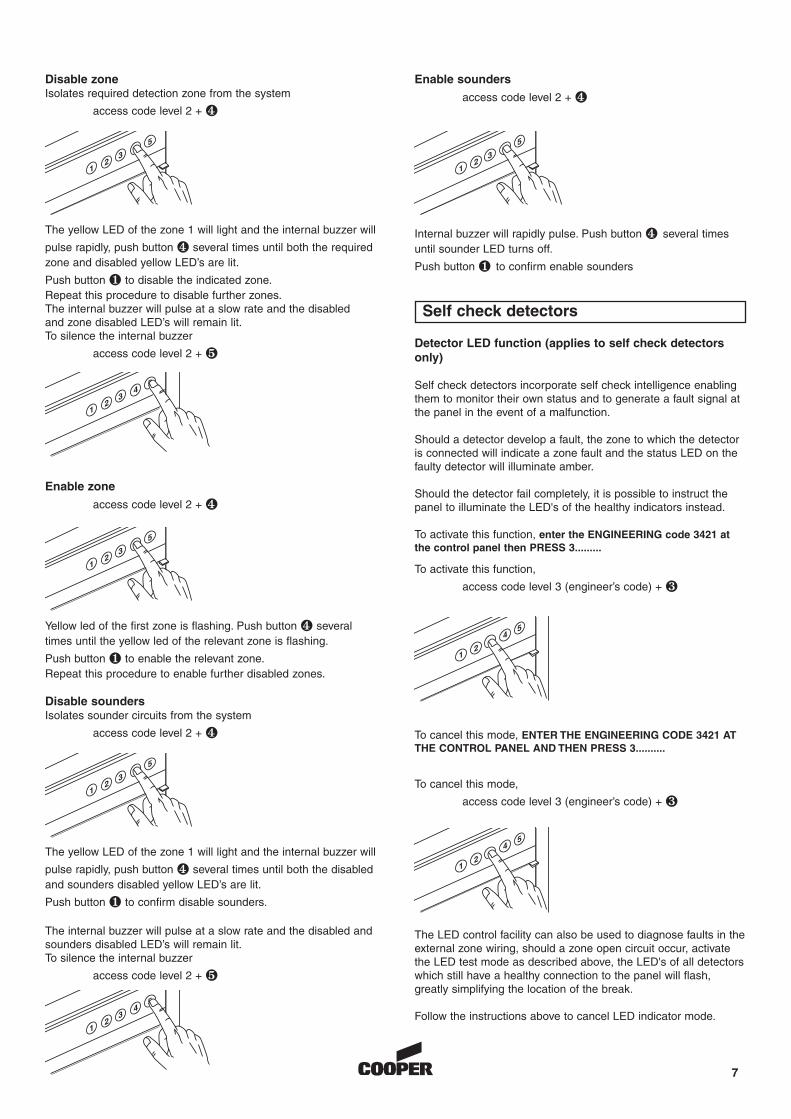
The yellow LED of the zone 1 will light and the internal buzzer will
pulse rapidly, push button � several times until both the requiredzone and disabled yellow LED’s are lit.
Push button � to disable the indicated zone.Repeat this procedure to disable further zones.The internal buzzer will pulse at a slow rate and the disabledand zone disabled LED’s will remain lit.To silence the internal buzzer
access code level 2 + �
The yellow LED of the zone 1 will light and the internal buzzer will
pulse rapidly, push button � several times until both the disabledand sounders disabled yellow LED’s are lit.
Push button � to confirm disable sounders.
The internal buzzer will pulse at a slow rate and the disabled andsounders disabled LED’s will remain lit.To silence the internal buzzer
access code level 2 + �
Enable zone
access code level 2 + �
Yellow led of the first zone is flashing. Push button � severaltimes until the yellow led of the relevant zone is flashing.
Push button � to enable the relevant zone.Repeat this procedure to enable further disabled zones.
3
12
5
Disable soundersIsolates sounder circuits from the system
access code level 2 + �
3
12
5
Enable sounders
access code level 2 + �
Internal buzzer will rapidly pulse. Push button � several timesuntil sounder LED turns off.
Push button � to confirm enable sounders
3
12
5
Disable zoneIsolates required detection zone from the system
access code level 2 + �
3
12
5
12
34
5
12
34
5
Detector LED function (applies to self check detectorsonly)
Self check detectors incorporate self check intelligence enablingthem to monitor their own status and to generate a fault signal atthe panel in the event of a malfunction.
Should a detector develop a fault, the zone to which the detectoris connected will indicate a zone fault and the status LED on thefaulty detector will illuminate amber.
Should the detector fail completely, it is possible to instruct thepanel to illuminate the LED's of the healthy indicators instead.
To activate this function, enter the ENGINEERING code 3421 atthe control panel then PRESS 3.........
To cancel this mode, ENTER THE ENGINEERING CODE 3421 ATTHE CONTROL PANEL AND THEN PRESS 3..........
The LED control facility can also be used to diagnose faults in theexternal zone wiring, should a zone open circuit occur, activatethe LED test mode as described above, the LED's of all detectorswhich still have a healthy connection to the panel will flash,greatly simplifying the location of the break.
Follow the instructions above to cancel LED indicator mode.
Self check detectors
To activate this function,
access code level 3 (engineer’s code) + �
To cancel this mode,
access code level 3 (engineer’s code) + �
12
45
12
45
Maintenance
8
GeneralIt is vital that the fire alarm system is checked for correctoperation as per the requirements of BS5839.
Daily inspection (by user)The panel should be visually inspected daily to ensure that thegreen ‘power on’ indicator is lit and that no fault indication isshowing. Notify any fault indication to your maintenance company.
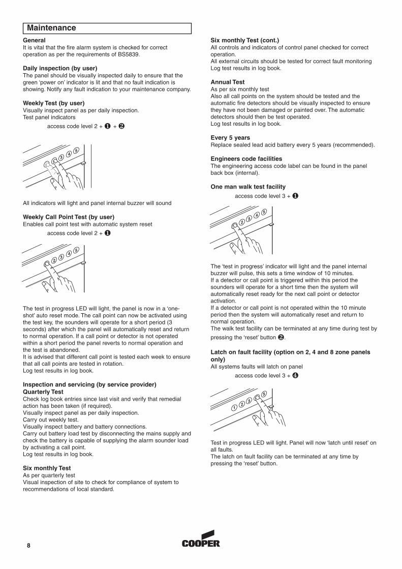
Weekly Test (by user)Visually inspect panel as per daily inspection.Test panel indicators
access code level 2 + � + �
All indicators will light and panel internal buzzer will sound
Weekly Call Point Test (by user)Enables call point test with automatic system reset
access code level 2 + �
The test in progress LED will light, the panel is now in a ‘one-shot’ auto reset mode. The call point can now be activated usingthe test key, the sounders will operate for a short period (3seconds) after which the panel will automatically reset and returnto normal operation. If a call point or detector is not operatedwithin a short period the panel reverts to normal operation andthe test is abandoned.It is advised that different call point is tested each week to ensurethat all call points are tested in rotation.Log test results in log book.
Inspection and servicing (by service provider)Quarterly Test Check log book entries since last visit and verify that remedialaction has been taken (if required).Visually inspect panel as per daily inspection.Carry out weekly test.Visually inspect battery and battery connections.Carry out battery load test by disconnecting the mains supply andcheck the battery is capable of supplying the alarm sounder loadby activating a call point.Log test results in log book.
Six monthly TestAs per quarterly testVisual inspection of site to check for compliance of system torecommendations of local standard.
The ‘test in progress’ indicator will light and the panel internalbuzzer will pulse, this sets a time window of 10 minutes.If a detector or call point is triggered within this period thesounders will operate for a short time then the system willautomatically reset ready for the next call point or detectoractivation.If a detector or call point is not operated within the 10 minuteperiod then the system will automatically reset and return tonormal operation.The walk test facility can be terminated at any time during test by
pressing the ‘reset’ button �.
Latch on fault facility (option on 2, 4 and 8 zone panelsonly)All systems faults will latch on panel
access code level 3 + �
Test in progress LED will light. Panel will now ‘latch until reset’ onall faults.The latch on fault facility can be terminated at any time bypressing the ‘reset’ button.
Six monthly Test (cont.)All controls and indicators of control panel checked for correctoperation.All external circuits should be tested for correct fault monitoringLog test results in log book.
Annual TestAs per six monthly testAlso all call points on the system should be tested and theautomatic fire detectors should be visually inspected to ensurethey have not been damaged or painted over. The automaticdetectors should then be test operated.Log test results in log book.
Every 5 yearsReplace sealed lead acid battery every 5 years (recommended).
Engineers code facilitiesThe engineering access code label can be found in the panelback box (internal).
One man walk test facility
access code level 3 + �
34
5
34
2
5
34
2
5
3
12
5
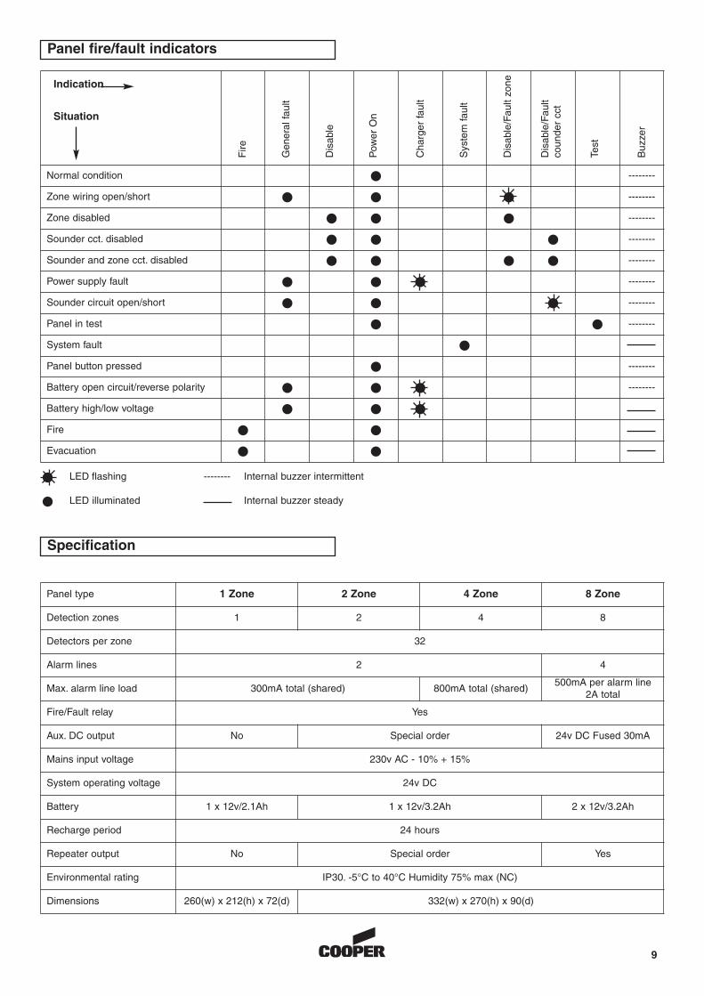
Panel fire/fault indicators
Specification
9
Normal condition � --------
Zone wiring open/short � � � --------
Zone disabled � � � --------
Sounder cct. disabled � � � --------
Sounder and zone cct. disabled � � � � --------
Power supply fault � � � --------
Sounder circuit open/short � � � --------
Panel in test � � --------
System fault �
Panel button pressed � --------
Battery open circuit/reverse polarity � � � --------
Battery high/low voltage � � �
Fire � �
Evacuation � �
Gen
eral
faul
t
Fire
Dis
able
Pow
er O
n
Cha
rger
faul
t
Sys
tem
faul
t
Dis
able
/Fau
lt zo
ne
Dis
able
/Fau
ltco
unde
r cc
t
Test
Buz
zer
Panel type 1 Zone 2 Zone 4 Zone 8 Zone
Detection zones 1 2 4 8
Detectors per zone 32
Alarm lines 2 4
Max. alarm line load 300mA total (shared) 800mA total (shared)500mA per alarm line
2A total
Fire/Fault relay Yes
Aux. DC output No Special order 24v DC Fused 30mA
Mains input voltage 230v AC - 10% + 15%
System operating voltage 24v DC
Battery 1 x 12v/2.1Ah 1 x 12v/3.2Ah 2 x 12v/3.2Ah
Recharge period 24 hours
Repeater output No Special order Yes
Environmental rating IP30. -5°C to 40°C Humidity 75% max (NC)
Dimensions 260(w) x 212(h) x 72(d) 332(w) x 270(h) x 90(d)
�
�
LED flashing
LED illuminated
Internal buzzer intermittent
Internal buzzer steady
--------
Indication
Situation

PINSTFX2200GENR1PR000-00-513-01